

Page 1
Installation and Operation Manual
Thermo Scientific® Harris MBF-700
Refrigeration System
Page 2

©
20 Thermo Fisher Scientific. All rights reserved.
®
“Suva
” is a registered trademark of DuPont.
All other trademarks are the property of Thermo Fisher Scientific Inc. and
its subsidiaries.
Page 3

Table of Contents
Table of Contents
Section 100 – Product Introduction .............................................. 1
Freezer Overview ........................................................................... 1
General Construction .................................................................... 2
Control Panel ............................................................................... 3
Liquid CO2 (LCO2) Backup System .......................................... 4
Section 200 – Installation And Operation ..................................... 17
Installation Check List ................................................................... 17
Operator's Responsibilities ............................................................ 17
Water-cooled Condensing Unit Connections ............................. 19
Cleaning The Freezer Surfaces ....................................................... 21
Storage .......................................................................................... 21
Section 300 – Theory Of Operation .............................................. 22
Overview ....................................................................................... 22
Sequence Of Operation ................................................................. 22
Systems Description ...................................................................... 23
Refrigeration Systems .................................................................. 23
Safety Devices ............................................................................. 24
Temperature Control .................................................................. 24
LCO2 Backup System ................................................................ 25
Halo Passes ................................................................................. 26
Operation ...................................................................................... 26
Cascade Refrigeration System ..................................................... 26
Main Temperature Control ........................................................ 27
Backup Temperature Control System ......................................... 29
Section 400 – Maintenance And Service ........................................ 31
Preventive Maintenance Procedures .............................................. 31
Air Cooled Condensers ............................................................... 31
Compressor Oil Level ................................................................. 31
fan Motors .................................................................................. 31
Defrosting ................................................................................... 31
Thermo Fisher Scientific Generic MBF700 Service Manual i
Page 4

Table of Contents
LCO2 Vent ................................................................................ 32
Trouble Shooting Guide ............................................................... 32
Contactors And Relays ................................................................ 39
Compressor Motors, Three Phase ............................................... 39
Partial Or Complete Loss Of Refrigeration ................................. 40
Checking Refrigerant Charge ...................................................... 40
Installing Gauges ........................................................................ 41
Leak Testing, Repairing And Charging – An Overview ............... 41
Repair Procedures .......................................................................... 43
Compressor Replacement ............................................................ 43
Backflush Procedure ................................................................... 46
Evacuation Procedure ................................................................. 48
Charging Procedure -- 1st (High) Stage ...................................... 51
Charging Procedure -- 2nd (Low) Stage ...................................... 51
Thermocouple Labeling And Locations ...................................... 53
temperature Calibration .............................................................. 53
Section 500 – Appendix ................................................................ 55
Refrigeration System Data ............................................................ 56
Service Parts List ........................................................................... 57
ii Generic MBF700 Service Manual Thermo Fisher Scientific
Page 5
SECTION 100 – PRODUCT INTRODUCTION
SECTION 100 –
PRODUCT
INTRODUCTION
FREEZER OVERVIEW This unit is a low temperature freezer designed to operate with a chamber
temperature in the range of –65 to –85 °C (-85 to –121 °F) and in an
ambient temperature range of 15 to 32 °C (59 to 89.6 °F).
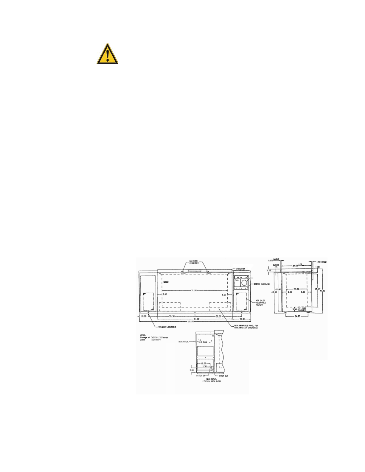
The cabinet configuration is that of a rectangular solid measuring 121” long
(3 07.3cm) x 47.5” high (120.7cm) with lid and all covers in place x
35.312” deep (89.7cm). When installing the freezer, a minimum of six
inches (6”) must be provided on all sides of the freezer for proper air
circulation.
Weight is 1510 lbs. (684.8Kg) net.
Shipping weight is 1790 lbs (811.8Kg).
Power Requirements: 208V - 230VAC, 3 Phase , 60Hz
120VAC, 1 , 60Hz (LCO2 backup system)
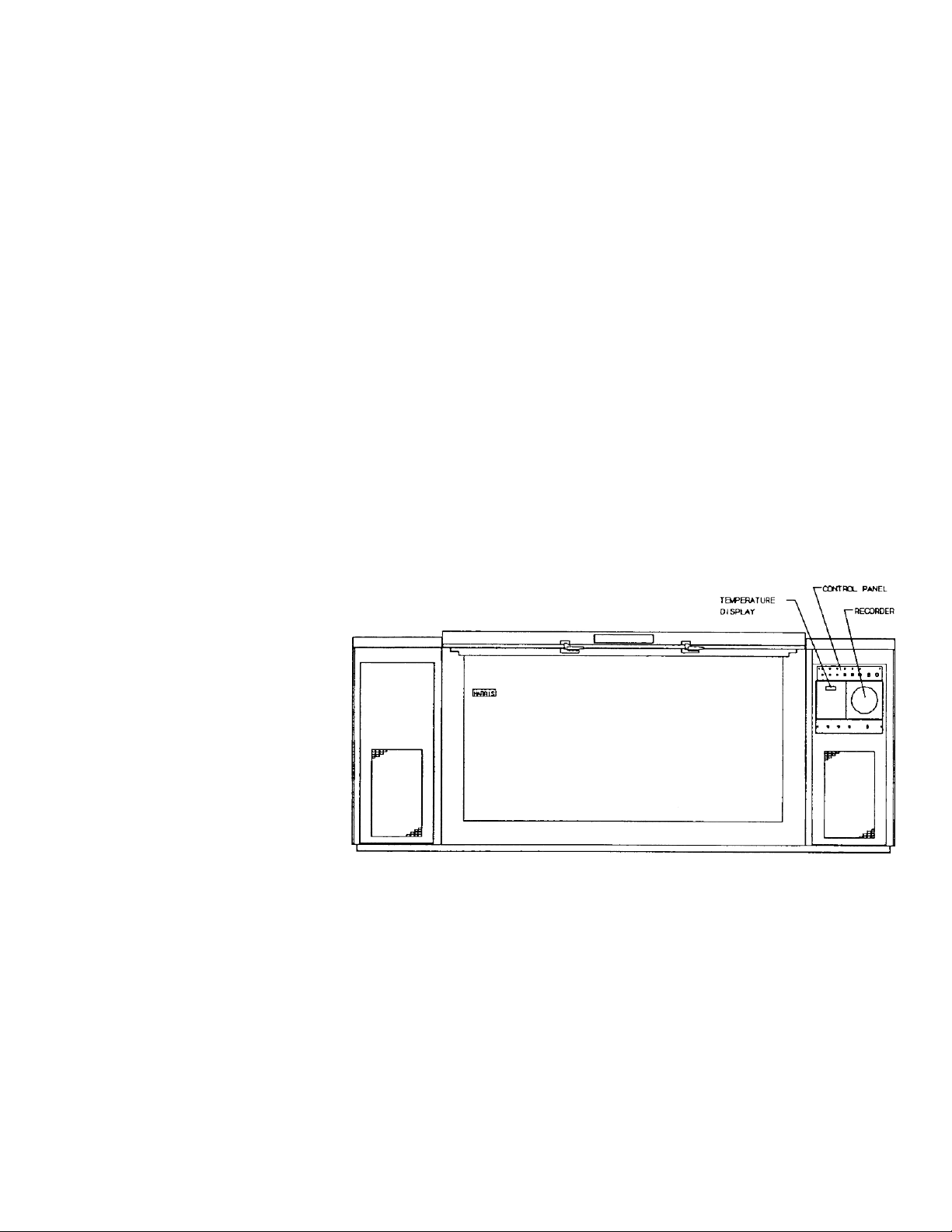
Figure 1. General Freezer Outline (see Figure 3 for control panel
details)
The interior useable space is also rectangular. The four corners are coved.
With insulating sub lids in place it measures 71” long (180.3cm)x 35.37”
high (89.9cm) x 22.63” deep (57.5cm). The interior volume is 31 Ft.
(878.7 liters.)
The cabinet is insulated with nominal 5” of foamed-in-place polyurethane
insulation.
Thermo Fisher Scientific Generic MBF700 Service Manual 1
Page 6
SECTION 100 – PRODUCT INTRODUCTION
CAUTION Do not discard the sub lids. They are necessary for the
operation of the unit.
The refrigeration arrangement employed in this freezer is a specially
designed assembly using four hermetic motor compressors. This design is
termed a “redundant cascade system”. A more complete description of this is
in the pages following. Stainless steel storage racks for inventory control are
avaiable as an option and must be ordered separately.
GENERAL
CONSTRUCTION
The lid is held tightly closed by means of cam locks having provision for a
user supplied padlock.
Durable corrosion protection is provided by an electrostatically applied
epoxy fused powder coating over cold rolled steel.
To provide a redundant refrigeration system, the inner tank is double
wrapped with copper tubing forming a dual circuit evaporator. In addition,
each of these circuits has its own compressor, condenser and liquid
refrigerant control (capillary tube). Each of the redundant systems will
support full operation to maintain the storage temperature. When set to
alternate between system “A” and system “B”, refrigeration is applied to the
freezer chamber alternating between systems on each cycle.
Figure 2. Cabinet Dimensional Drawing
2 Generic MBF700 Service Manual Thermo Fisher Scientific
Page 7
SECTION 100 – PRODUCT INTRODUCTION
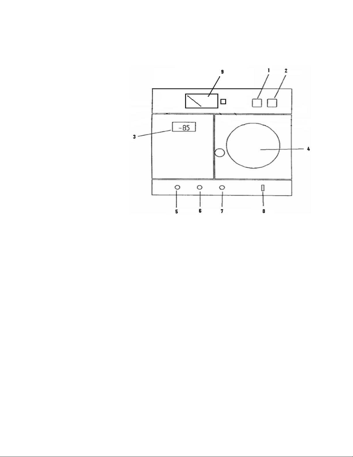
CONTROL PANEL All controls are located at the right end of the cabinet
Figure 3. Control Panel Detail
1. Key-operated alarm ON/OFF switch. Turns on local audio alarm.
2. Key-operated compressor ON/OFF switch. Turns on power to
compressors and control system.
3. Digital temperature indicator and primary control
4. Temperature recorder, 7-day, 6” diameter.
5. System “B” indicator light. “ON” when system “B” 1st stage
running.
6. System “A” indicator light. “ON” when system “A” 1st stage
running.
Thermo Fisher Scientific Generic MBF700 Service Manual 3
Page 8

SECTION 100 – PRODUCT INTRODUCTION
7. Alternate system alarm indicator light. “ON” when auxiliary control
causing both systems to operate.
8. Heater switch. Operates breaker strip condensate heater.
9. Battery meter. Displays state of battery charge when button is
pressed.
The remote alarm contacts were developed to provide an alert for an alarm
condition. The remote alarm contacts are normally closed, and open during
an alarm event. The contacts are rated for a maximum of 36V3A
LIQUID CO2 (LCO2)
BACKUP SYSTEM
When connected to a user supplied siphon tank of liquid CO2, the backup
system will provide a source of backup refrigeration in case of power failure
to the mechanical refrigeration equipment. The control assembly operates
on 1 20VAC, 1, 60Hz. A backup battery supply is continuously charging for
operation of the backup system during power failure.
Installation
1. Place the LCO2 control system on top of the System B mechanical
section.
2. Connect the LCO2 supply to the back of the control system.
3. Connect theLCO2 distribution tube to the back of the unit.
4. Connect the LCO2 temperature sensor to the Mate-N-Loc
connector that hangs from the rear of System B mechanical section.
5. Connect the LCO2 control system harness to the Mate-N-Loc
connector that hangs from the rear of System B mechanical section.
6. The assembly of the LCO2 to the cabinet is now complete.
Note An LCO2 supply must be provided by the customer. The supply
pressure must be 900 – 1,000 PSIG.
4 Generic MBF700 Service Manual Thermo Fisher Scientific
Page 9
SECTION 100 – PRODUCT INTRODUCTION
7. Uncoil the tubing from the control unit and connect to the LCO2
tank or supply connection.
8. Turn on the LCO2 valve.
9. Refer to the Backup System Owners Manual for operation
instructions.
Note LCO2 backup systems are typically built with a relief valve set for
1,300 PSIG.
LCO2 Control System Battery Condition
The charge level light illuminates when the battery is below 80% of full
charge. It is also possible that the charge level light will illuminate when the
control system is dispensing LCO2.
Placing LCO2 control system in storage
CAUTION Any rise in temperature will cause a rapid rise of pressure of
liquid CO2 trapped in the supply line. After turning off the LCO2 supply,
bleed the supply line by lowering the LCO2 setpoint sufficiently to cause
the LCO2 solenoid to open. With the solenoid open, disconnect the supply
line from the backup system control unit.
After disconnecting the LCO2 supply line, set the LCO2 control to +50 oC
and plug the unit into the power supply. This will keep the battery charged
and prevent the solenoid from operating.
LIQUID CO
2 BACKUP REFRIGERATION
This accessory, when connected to a user supplied siphon tank of liquid
2, will provide a source of backup refrigeration in case of power failure to
CO
the mechanical refrigeration equipment. The control assembly for this
accessory operates over a range of 200VAC to 240VAC, 10, either 50Hz or
60Hz. There is a continuous charging battery backup power supply for
operation of the accessory during power failure.
Installation:
1. Place the LCO2 control system on top of the System B mechanical
section.
Thermo Fisher Scientific Generic MBF700 Service Manual 5
Page 10

SECTION 100 – PRODUCT INTRODUCTION
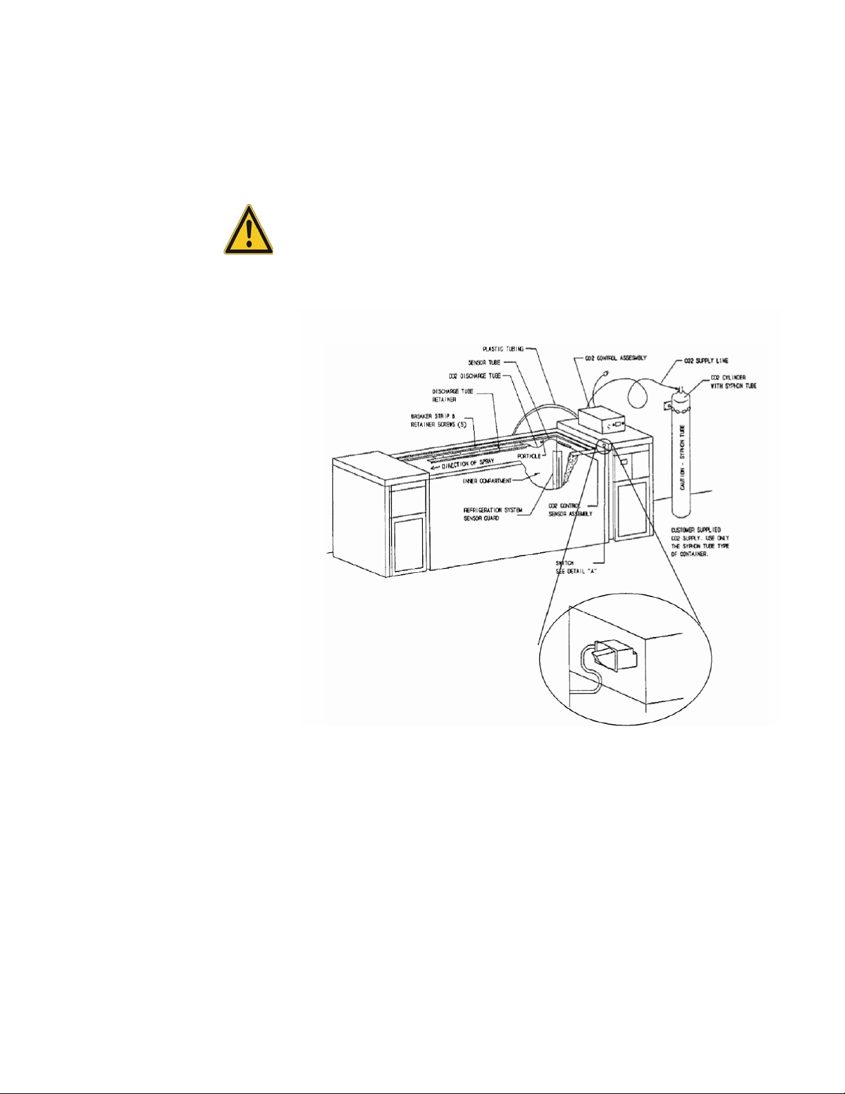
2. Place the CO2 control system on top of the freezer lid.
3. Locate the switch hole in the left hand side of the right hand
machine compartment cover and remove the cover plate that was
factory installed.
4. Remove the machine compartment cover by locating and removing
the screws at the back and at front securing the cover to the housing.
5. Locate the lid switch in the accessory kit.
6. Locate the leads from the control unit with two-prong connector.
Feed the leads through the hole provided in the back of the unit,
route through machinery compartment to the left front and up
through the second hole provided. Then feed the leads through the
switch hole provided in the machinery compartment cover and
connect to the switch terminals. Snap the switch into the hole
making sure that the curved side of the plunger is on the bottom
side.
7. Replace the machinery compartment cover securing with the screws
front and back.
8. Identify the CO2 discharge and control assembly mounted in the
perforated housing.
9. Remove the coiled control bulb and the CO
2 discharge tube from
the housing, insert the bulb through the rear cabinet porthole and
reassemble the bulb to the housing inside the cabinet. Mount the
housing to the right inside wall of the cabinet using two of the three
factory installed screws. Route the CO2 discharge tube through the
porthole and, after loosening the screws securing the rear breaker
strip, slide the discharge tube under the retainer strip and re-tighten
the screws.
10. The assembly of the CO
2 to the cabinet is now complete.
6 Generic MBF700 Service Manual Thermo Fisher Scientific
Page 11

SECTION 100 – PRODUCT INTRODUCTION
Note An uninsulated CO2 supply cylinder with siphon tube must be
provided by the customer. The siphon tube allows liquid CO2 to be drawn
from the cylinder. The supply pressure must be between 600 and 1050 psig.
The supply temperature must be between 7 oC and 31 oC (45 oF and 88
o
F). DO NOT INSTALL A PRESSURE REGULATOR BETWEEN THE
CYLINDER AND THE CONTROL UNIT. If you are unfamiliar with
handling compressed gases, refer to a qualified service technician.
11. Uncoil the tubing from the control unit and connect to the CO2
tank or supply connection.
12. Turn on the CO2 valve.
13. Adjust the temperature setpoint to the coldest position.
14. Connect the power cord of the control unit to the voltage source
indicated on the unit serial plate.
15. Open and close the freezer lid to insure that the CO2 dispenses into
the freezer when the lid is closed and does not dispense when the lid
is open. If there is no discharge, check to see that the wires are
fastened securely to the lid switch and that the switch plunger is
actually depressed.
°
16. Set the temperature control at a minimum of 5
operating temperature of the freezer but never colder than -70
°
Setting colder than -70
C will result in a continuous dispensing of
C warmer than the
°
C.
the CO2 supply.
CO
2 Control System Battery Condition:
The charge level light comes ON when the battery is below 80% of full
charge. It is also possible that the charge level light will come on when the
control system is dispensing CO2.
When placing the control unit in storage, set the CO2 control to +50 °C and
plug the unit into the power supply. This will keep the battery charge and
prevent the solenoid from operating. The capillary tube leading from the
control unit to the control bulb may be coiled up for storage but do not
make coils any smaller than 4 inch diameter. There are two screws provided
Thermo Fisher Scientific Generic MBF700 Service Manual 7
Page 12
SECTION 100 – PRODUCT INTRODUCTION
in the back of the control cabinet that match the slots in the back of the
control bulb housing. Slip the slots in the housing under the screw heads
and tighten. This will hold the housing and bulb securely to prevent
damage.
CAUTION Do not turn off the CO2 supply trapping liquid in the supply
line. Any rise in temperature will cause a rapid rise of pressure that will
rupture the protective disk in the control unit.
Figure 4. CO2 Backup System
COBEX ELECTRONIC, 7-DAY CIRCULAR CHART
TEMPERATURE RECORDER
This product includes a manufacturer-installed electronic temperature
recorder. These instructions are provided to assist with the initial set-up,
operation and general maintenance of the recorder.
8 Generic MBF700 Service Manual Thermo Fisher Scientific
Page 13
SECTION 100 – PRODUCT INTRODUCTION
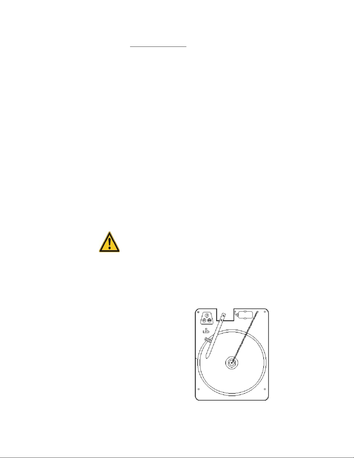
CobexRecorder Face
Setup and Operation
The recorder has been factory-installed, programmed, and calibrated for
your new system. Operation will begin when the system is powered on. To
prepare the recorder to function properly, you should perform the following
steps:
1. Review figure below to become familiar with recorder features.
2. Open recorder door to access recorder.
3. For back-up power, connect the 9 volt DC battery located at the
recorder’s upper right hand corner.
4. Install clean chart paper (refer to Changing Chart Paper,below).
5. Remove plastic cap from pen stylus (ink or pressure sensitive) and
close recorder door.
Note Recorder may not respond until the system reaches temperatures
within the recorder’s range.
This should complete operator setup. Additional information is provided
for maintenance and troubleshooting as required.
MAINTENANCE
Thermo Fisher Scientific Generic MBF700 Service Manual 9
Page 14

SECTION 100 – PRODUCT INTRODUCTION
Power Supply
The recorder normally operates with AC power when the system is
operating. If AC power fails the LED indicator flashes to alert you to a
power failure. The recorder will continue sensing cabinet temperature and
the chart will continue turning for approximately 24 hours with back-up
power provided by the 9 volt battery. Both the battery and main power are
O.K. when the LED indicator glows continuously.
Changing Chart Paper
Locate the pressure sensitive buttons at the front, upper left of the recorder
panel. Press and hold the change chart button (#3) for 1 second. Pen will
move off scale. Unscrew center nut, remove old chart paper, and install new
chart paper. Carefully align the day and time with the reference mark on the
recorder panel. Replace center nut and hand tighten. Press the change chart
button (#3) again to resume temperature recording.
Changing Marker Pen
For recorders having a marker pen rather than a stylus for pressure-sensitive
paper, the pen provided is a fiber-tipped cartridge type, and is attached to
the pen arm. As the pen ink supply runs out, the pen color will become
lighter indicating the pen should be replaced. To install a new pen, loosen
the (2) screws at the top of the arm. Slip the pen cartridge out and remove
the “U” shaped clip tab from the pen. Discard the old pen. Insert the clip
tab into a new pen and then re-fasten to the pen arm.
Changing Temperature Range Program
This recorder is capable of operating in multiple pre-programmed
temperature ranges. The correct temperature range program was selected
upon factory installation and is retained even during power interruptions. If
the temperature range is wrong for any reason, it can be easily
reprogrammed as follows:
• Press change chart button #3. Pen arm will move off scale, LED will
glow continuously.
• Press and hold button #1 for 5 seconds. LED indicator will begin
flashing.
• The number of flashes corresponds to the temperature range program as
follows:
10 Generic MBF700 Service Manual Thermo Fisher Scientific
Page 15

SECTION 100 – PRODUCT INTRODUCTION
No. of Flashes Temperature Range Application Option #
1 -40 to +25°C Refrigerators 6*83-7*
2 -115 to+50°C ULT’s 6*83-6*
3 -200 to 0°C Cryogenic 6*83-5*
4 0 to +60 Newer Units Only
Change program to the “-115 °C to +50°C” temperature range by using the
left (#1) button to increase and the right (#2) button to decrease the number
of flashes. Press the change chart button (#3) when the desired program is
set. Pen will move to the outer edge of the chart for 5 seconds. After 5
seconds, the LED indicator will glow continuously and the pen arm will
move to begin recording temperature.
Calibration
Note The pen does not begin to move until the button is held for 5 seconds.
This recorder has been accurately calibrated at the factory and retains
calibration even during power interruptions. If required, however,
adjustments can be made as follows:
1. Run unit continuously at bottom-out temperature. Continue steady
operation at least 30 minutes to provide adequate time for recorder
response.
2. Measures cabinet center air temperature with a calibrated
temperature monitor.
3. Compare recorder temperature to center air temperature. If
necessary, adjust recorder by pressing the left (#1) and right (#2)
chart buttons.
Thermo Fisher Scientific Gener ic MBF700 Service Manual 11
Page 16

SECTION 100 – PRODUCT INTRODUCTION
COBEX RECORDER TROUBLESHOOTING GUIDE
LED Flashing Low Battery
Replace with a FRESH 9v alkaline battery. Battery must be
new.
No AC Power
1. Remove battery.
2. If LED goes out, then no power is getting to the unit.
3. Check power and transformer connections.
Transformer secondary is approximately 1 5v AC.
4. Be sure transformer is wired for proper voltage.
LED Out or
Unit “Dead”
Possible bad Board
1. Remove battery.
2. Disconnect or turn off power.
3. Restore power.
4. Reconnect battery.
5. Return entire unit if not working.
Wro ng Ra ng e
1. Push #3 “Chart Change”.
2. With pen off chart, hold #1 for 7 seconds.
3.
Release. (
Note
: No range recall).
4. Green LED Flashes.
5. Push #1 or #2 to change:
• 1 flash -40 to +25C
• flashes -115 to+50C
• flashes -200 to 0C
• flashes 0 to +60C (newer units only)
6. Push #3 again.
12 Generic MBF700 Service Manual Thermo Fisher Scientific
Page 17
Not Calibrated Calibrate Recorder
1. Push #3. Pen comes off chart.
2. Push #3 again. Pen stops briefly on returning to
chart. Stopping point should be at edge of chart. If
not perform the following:
3. Be sure pen arm is aligned with pen arm bracket. If
not, loosen screws a adjust. During stopping interval
adjust pen arm using #1 and #2 to align pen arm with
edge of chart.
4. Place probe in cold water for 5 min. Slow response.
5. Measure the water temperature with a thermometer.
6. Adjust calibration using #1 and #2 to make recorder
read same temperature as thermometer.
7. Put probe back into solution.
8. Wait 5 minutes and adjust to cabinet temperature.
Bad Probe
1. Check probe connections
• Red wire connected to J6 pin 1
• Both black wires to J6 pin 2
2. Measure voltage across J6 approximate voltages are as
follows:
• -150C=35mv
• -85C=75mv
• -30C=1 00mv
• 3.5C=1 10mv
• 25C = 120mv (ambient)
• Probe open circuit 1 .23v (approximately)
• Probe short circuit = 0.0v (recorder possibly) faulty.
Replace probe. If still 0.0v return/replace recorder.
• >2.0v = Replace recorder and probe.
If probe voltage is off by more than a factor of 2 then probe
is faulty.
Possible bad Board
1. Remove battery.
2. Disconnect or turn off power.
3. Restore power.
4. Reconnect battery.
5. Return entire unit if not working.
SECTION 100 – PRODUCT INTRODUCTION
Thermo Fisher Scientific Gener ic MBF700 Service Manual 13
Page 18

SECTION 100 – PRODUCT INTRODUCTION
Pen Goes to
Center
Wro ng Ra ng e
1. Momentarily depress button #3 (“Chart Change”
button).
2. With pen off chart, hold #1 for 7 seconds.
3. Release. (Note: No range recall).
4. Green LED Flashes.
5. Momentarily depress #1 or #2 to change:
• 1 flash -40 to +25C
• 2 flashes -115 to+50C
• 3 flashes -200 to 0C
• 4 flashes 0 to +60C (newer units only)
6. Momentarily depress “Chart Change” button again.
7. Not calibrated (see below)
Not Calibrated Calibrate Recorder
1. Push #3. Pen comes off chart.
2. Push #3 again. Pen stops briefly on returning to
chart. Stopping point should be at edge of chart. If
not perform the following:
3. Be sure pen arm is aligned with pen arm bracket. If
not, loosen screws a adjust. During stopping interval
adjust pen arm using #1 and #2 to align pen arm with
edge of chart.
4. Place probe in cold water for 5 min. Slow response.
5. Measure the water temperature with a thermometer.
6. Adjust calibration using #1 and #2 to make recorder
read same temperature as thermometer.
7. Put probe back into solution.
8. Wait 5 minutes and adjust to cabinet temperature.
Bad Probe
1. Check probe connections
• Red wire connected to J6 pin 1
• Both black wires to J6 pin 2
2. Measure voltage across J6 approximate voltages are as
follows:
• -150C=35mv
• -85C = 75mv
• -30C=100mv
• 3.5C=110mv
• 25C = 120mv (ambient)
• Probe open circuit 1 .23v (approximately)
• Probe short circuit = 0.0v (recorder possibly) faulty. Replace
probe. If still 0.0v return/replace recorder.
• >2.0v = Replace recorder and probe.
• If probe voltage is off by more than a factor of 2 then
probe is faulty.
14 Generic MBF700 Service Manual Thermo Fisher Scientific
Page 19

SECTION 100 – PRODUCT INTRODUCTION
Pen Not
Printing
Chart Loose
1. .Tighten chart knob
2. Attempt to turn chart counter-clockwise
3. If chart turns then tighten knob more
No Pen Pressure
1. Unscrew pen arm
2. Bend pen arm slightly downward
3. Reattach
Pen Indicating
Wrong Temp
Pen Will Not
Come
Completely
OffChart
4. Recalibrate (see “Not Calibrated”)
Not Calibrated
Recalibrate (see “Not Calibrated”)
Wrong Chart
Be sure proper chart is used with selected range
• 1 Flash -40 to +25C
• 2 Flashes -115to+50C
• 3 Flashes -200 to 0C
• 4 Flashes 0 to -+60C (newer units only)
Pen Arm Displaced
1. Unscrew pen arm
2. Align pen arm with pen arm bracket
3. Recalibrate (see “Not Calibrated”)
Thermo Fisher Scientific Gener ic MBF700 Service Manual 15
Page 20

SECTION 100 – PRODUCT INTRODUCTION
Pen Arm
Oscillating
No Recorded
Line
Not Calibrated
Recalibrate (see “Not Calibrated”)
No Pen Pressure
1. Unscrew pen arm.
2. Bend pen arm slightly downward.
3. Reattach
4. Recalibrate (“Not Calibrated”).
Chart Loose
1. Tighten chart knob.
2. Attempt to turn chart counter-clockwise.
3. If chart turns, tighten knob more.
16 Generic MBF700 Service Manual Thermo Fisher Scientific
Page 21
SECTION 200 – INSTALLATION AND OPERATION
SECTION 200 –
INSTALLATION
Do not attempt to operate this freezer until the preceding Installation Check
List steps have been completed
AND OPERATION
INSTALLATION
CHECK LIST
The freezer is in place.
The freezer has been leveled.
Check freezer data plate voltage.
Check supply voltage is the same as data plate.
Check that power panel circuit protection rating does not exceed that indicated on the
data plate.
LCO2 supply valve is Off
Date Initial
Facility monitoring system connected to freezer’s remote alarm contacts.
If applicable, water supply and discharge are connected if unit uses a water-cooled
condenser in accordance with WATER-COOLED CONDENSING UNIT
CONNECTIONS, page 19.
No product loaded in freezer.
Main building power panel breakers are On.
Using key provided, turn the compressor key switch to ON.
Set primary control set points. (see Appendix B)
The frame heater switch (#8, Figure 3).is shipped from the factory in the OFF position.
Turn frame heater switch ON only if the humidity is sufficiently high that it may cause
frost on the strips.
Turn LCO2 supply valve On after cabinet reaches operating temperature.
OPERATOR'S
RESPONSIBILITIES
Note These paragraphs define the Operator's responsibilities for reporting
trouble symptoms on startup of the freezer and also observing its operation
on an ongoing basis in order to prevent any mechanical or electrical failures
that could result in loss of blood products.
Thermo Fisher Scientific Gener ic MBF700 Service Manual 17
Page 22

SECTION 200 – INSTALLATION AND OPERATION
Frequency Of
Description Of Tasks, Observations & Record Keeping Requirements
Ta s k
Once on first
start
a. Time required for initial pulldown. If only partial loss of the refrigerant has occurred, the sign
°
will be slow pulldown time required reaching -80
C. Pulldown time should be 2.5 hours or
less. If it is more than 2.5 hours, the technician must either determine the cause and the
remedy therefore or IMMEDIATELY SHUT DOWN THE FREEZER until the problem can
be diagnosed and remedied.
b. Carefully record the first few on-off periods with freezer empty, and then again loaded with
product. Keep this record with the freezer at all times for future reference in troubleshooting.
c. If the installation is made in an air-conditioned area, there will not be much, if any, change in
cycle. However, if the ambient temperature is subject to changes, make a record of cycle times
at these various ambient temperatures.
Daily a. Listen for rattles. If refrigerant-carrying copper tubing is allowed to rub against other tubes or
any object, a leak will very quickly occur resulting in loss of the refrigerant charge and cabinet
temperature.
b. Watch the system operation indicator light. It should not be showing the same system always
operating. For instance, when system A has been operating and shuts off, system B should start
on the next control call for cooling.
Weekly a. Air-Cooled units only: clean the condenser air filter when its original jet-black color has
changed. Attention to this detail will assure shortest running times and prolong the life of the
freezer.
b. Make sure the lid closes without interference and that sub lids are always in place.
c. Ensure that the sub lids are in place.
d. Verify that the LCO2 vent is free of frost accumulation.
On Using a. Watch for lid gasket tears. Streaks of frost will collect inside the freezer at the precise location
of the torn or cut gaskets.
b. Defrost the cabinet if frost or ice build-up exceeds 1/4” thickness: remove product,
turn power key switch Off, leave unit open 48 hours, remove moisture, restart unit.
Call the Maintenance Department or the manufacturer’s Technical Service
group (1-800-438-4851) for assistance.
18 Generic MBF700 Service Manual Thermo Fisher Scientific
Page 23

WATER-COOLED
CONDENSING UNIT
CONNECTIONS
SECTION 200 – INSTALLATION AND OPERATION
CAUTION ONLY QUALIFIED REFRIGERATION TECHNICIANS
ARE TO MAKE CONNECTIONS OR ADJUSTMENTS.
The MBF700 can be purchased with air-cooled condenser, water-cooled
condenser, or both. If purchased with water-cooled condensers, there are
two water supply and two water discharge connections to be made at the
rear of the cabinet (see Figure 12) if you wish to use the water cooling
feature:
1. Locate the machine sections at each end of the freezer as you face the
rear of the cabinet.
2. At the bottom of each machine section are two 3/8” O.D. copper
tubes stubbed out through the cabinet grille (see diagram, next
page). The outermost tubes are the COLD WATER INLET and the
inner-most tube is the WATER OUTLET.
• The four tubes terminate with 3/8” 45 ° SAE flare nuts.
Note If it is necessary to reship these units and water has been connected in
the past, the lines must be blown clear with compressed air in order to
preclude freezing and rupturing the water cooled condenser.
There are normally three possible sources of cooling water for these freezers,
and any one may be satisfactory used. They are:
1. City water supply, discharge water wasted to drain.
2. Chilled water from a building air conditioning chiller. In this case,
the discharge water goes back to the chilled water loop and is
recirculated.
3. Cooling tower water supply, discharge water goes back to the tower
water loop.
Factory specification for maximum water supply temperature is 85 °F. The
automatic water regulating valve allows use of any of these sources. Seasonal
water temperature changes may require slight adjustment of the water
regulating valve. The factory setting is 195 PSIG.
Thermo Fisher Scientific Gener ic MBF700 Service Manual 19
Page 24

SECTION 200 – INSTALLATION AND OPERATION
The Selector Ball Valve can be accessed by removing the end cover on each
of the machine compartments.
The valve may be identified by the square wrench flats on its top. The
flow-indicating arrow will be perpendicular to the tubing when the valve is
closed, and parallel to the tubing when the valve is open.
Adjustment of the Selector Ball Valve is to be performed only by a qualified
refrigeration technician.
Note
• For air cooling only, do not connect water and leave valve closed.
• For use with water cooling, connect water and open the valve.
To adjust the automatic water regulating valve for best operating economy,
install a head pressure gauge; with the compressor operating, turn the
adjusting stem (located on top of the valve) until a head pressure of 195
PSIG is measured. Clockwise rotation of the adjusting stem lowers the head
pressure; counterclockwise rotation raises the head pressure.
20 Generic MBF700 Service Manual Thermo Fisher Scientific
Page 25

SECTION 200 – INSTALLATION AND OPERATION
CLEANING THE
FREEZER SURFACES
STORAGE Before placing the freezer in storage, turn the key switch to Off, unplug the
The inside and outside of the freezer are coated with a heat fused epoxy
powder finish. It may be cleaned with any non-abrasive cleaner such as hand
dish washing detergent. To prevent odors on the inside of the freezer after
cleaning, it is recommended that, after cleaning with detergent, the entire
surface be wiped with a clean cloth soaked with a solution of one-half(1/2)
gallon of water and one-quarter (1/4) cup of baking soda.
power cord, open the lid and allow the interior to warm up to ambient
temperature. Dry out the interior. Prop the lid open at least 6" and secure in
this position. If water cooling has been used, the water lines of BOTH water
cooled condensers must be blown out to prevent freezing.
Thermo Fisher Scientific Gener ic MBF700 Service Manual 21
Page 26

SECTION 300 – THEORY OF OPERATION
SECTION 300 –
THEORY OF
OPERATION
OVERVIEW The MBF700 utilizes alternately-operating redundant refrigeration systems
to maintain -85 °C while extending unit’s life and providing safety in the
event of a system failure. The electronic thermostat is backed up by an
electromechanical thermostat in case of primary control failure. A liquid
CO2 (LCO2) backup system provides safety in case of a catastrophic failure
of both systems. An external alarm connection is provided in case of an
alarm event: Loss of Power and Temperature Warm or Cold alarm.
SEQUENCE OF
OPERATION
When the compressor key switch (Figure 3, key #5) is initially turned On ,
the digital display will illuminate and read actual cabinet temperature.
Note It is normal for the top flange of the freezer cabinet to be warm during
operation of the systems. This is particularly true when the chamber is first
pulling down in temperature.
Within six minutes from the time the compressor power key switch is
energized, the red Backup Control alarm indicator will light and both first
stage compressors will start. They will run until the Reverse Acting Pressure
Control (RALPC) in the high stage system senses a pressure corresponding
to –40 °F, at which time the contact points will close. These points are
connected electrically in the low stage control circuit, causing the low stage
compressor to start. All four compressors will run continuously until cabinet
temperature has dropped to the adjustable setting of the mechanical Backup
Temperature Control setpoint. At this time, one cascade system will shut
down and the second cascade system will continue operating until the
electronic control setpoint is achieved. Typical pull down time from
ambient to -80°C is approximately 2.5 hours.
CAUTION Do not add any product load to a warm cabinet.
After the freezer is down to operating temperature, time and record the
“ON” and “OFF” cycles for the first few hours, noting the date, time of day
and the ambient temperature existing during each cycle. Record this data in
the front of this manual. This will provide a reference point for normal
operation to aid in future diagnostics.
22 Generic MBF700 Service Manual Thermo Fisher Scientific
Page 27

SECTION 300 – THEORY OF OPERATION
Typical Cycle Times at -80°C Setpoint
Power Supply Ambient Temperature On Cycle Duration
60Hz 75°F <27min
SYSTEMS
DESCRIPTION
REFRIGERATION SYSTEMS This freezer is equipped with redundant cascade refrigeration systems.
System “A” and System “B” are identical systems and each is capable of
maintaining the proper temperatures inside the freezer. Both systems are
“On/Off” systems, that is, when the control cycles on, the refrigeration
system is on at full capacity until the setpoint is achieved, at which time the
refrigeration system turns off. During a normal cycling condition, a
sequencing relay cycles first one system and then the other in order to
equalize operating time on both systems. However, when the cabinet is -70 °
C or warmer (such as during start-up or temperature control failure), a
backup mechanical temperature control will cause both systems to run.
The MBF-700 is equipped with identical and redundant cascade
refrigeration systems: System “A” and System “B”. Since each is capable of
maintaining the proper operating temperature inside the freezer, the product
load will be protected if one system should fail. System “A” is located on the
right-hand side and system “B” is located on the left. Both systems are
two-stage, low temperature cascade systems designed to maintain the rated
temperature of –85° C individually. System “A” is located on the right end
of the cabinet (behind the control panel) and System “B” is located on the
left end of the cabinet.
The key components of the A and B systems are carefully selected to achieve
the highest possible reliability of a mechanical freezer. The compressors are
1.5 HP industrial grade hermetic Bristols. These compressors have been
thoroughly tested to give reliable service at ULT conditions. The
condensers, interstage heat exchangers and evaporators on the high and low
stages are designed to provide a reliable operation at an ambient of as high as
32 C. A balancing operation of the stages combined with reliable
components makes MBF freezers suitable for many difficult applications
either in military or civilian fields.
Note When loading the freezer, leave a minimum space of two inches (2”)
between the under side of the freezer sub lids and the top of the topmost
packages for proper air circulation
Thermo Fisher Scientific Gener ic MBF700 Service Manual 23
Page 28

SECTION 300 – THEORY OF OPERATION
SAFETY DEVICES
(see Figure 7, notes 2,3 & 4)
Both first and second stage compressors are protected by an internal pressure
relief valve that will rapidly equalize the high and low sides of a given stage
in the event of a pressure imbalance greater than ~425 psi. Additionally, all
compressors are equipped with internal Klixon-type electrical overloads that
will break the motor circuit in the event of an overcurrent or
overtemperature condition. These two devices form a conservative
application envelope that the compressors should operate in. Under normal
conditions, the trip points are far from actual operating pressures. In the
event of a trip, both devices will automatically reset to their normal
operating mode once the triggering condition has been resolved.
A Reverse Acting Low-Pressure Control (RALPC) is mechanically
connected to the suction side of the first stage. It is however electrically
connected to the control side of the contactor for the second stage
compressor. When the first stage operates properly to trip at the setting of
the control ( 7 PSIG), the switch turns on the second stage compressor.
Therefore, it protects compressors in both stages from starting up
simultaneously. When the suction pressure rises to 21 psig, the 2nd stage is
de-energized to prevent flood back of liquid refrigerant to the 2nd stage
compressor.
High/Low Temperature Alarm (see Figure 9)
Through the main temperature control, both high and low process variable
alarm settings can be made. Should the freezer temperature deviate beyond
these settings, a relay will activate the master alarm circuitry and the control
panel will display an alarm message.
TEMPERATURE CONTROL In addition to the two refrigeration systems, redundancy is also incorporated
into the control system. Two temperature control systems are included – the
main and the back-up controls. The main control is an electronic Dixell
controller that provides the primary refrigeration demand signal, as well as
the high and low alarm setpoints. If the Primary control loses
communication with its sensor probe, it defaults to a 100% run condition.
The back-up control is an electromechanical thermostat. The factory has set
this thermostat 3-5 degrees warmer than the desired cabinet operating
temperature. When this safety thermostat functions, it indicates that the
second cascade system has been required to maintain proper temperature.
This can be the result of a significant heat load added to the freezer or, it can
mean that the system operating as primary at the time it occurred has a
problem. If a failure occurs, the failed system may be switched off by
24 Generic MBF700 Service Manual Thermo Fisher Scientific
Page 29

LCO2 BACKUP SYSTEM
SECTION 300 – THEORY OF OPERATION
selecting the functioning side on the rotary switch on top of the sequencing
relay. This will prevent the relay fron alternating sides, and the indicated
side will run repeatedly.
(see Figure 10)
This fully independent system provides backup cooling in the event both
mechanical refrigeration systems become inoperable, possibly due to a
power loss. The system is designed to meter liquid CO2 to the freezer
compartment with the liquid flow controlled by a battery-supplied solenoid
valve. The solenoid valve opens and closes in response to a closed-loop
electronic control system that monitors the freezer temperature. A built-in
charger maintains the battery charge; the battery is capable of operating the
backup system for approximately 24 hours, depending upon the age and
condition of the battery. The temperature probe, which is a 100 ohm
platinum RTD, is located on the right side of the freezer chamber. The
liquid CO2 distribution (supply) tube is located on the left side.
The LCO2 control is designed to delay injection until the temperature has
risen above the temperature setpoint. LCO2 will then be injected to
maintain the cabinet temperature at the desired setpoint. (Refer to the
LCO2 Operator’s Manual for instructions on programming the temperature
setpoints.
Liquid CO2 may be supplied from a bulk tank or a Dewar. Recommended
supply pressure is 900 to 1,000 PSIG. A compression fitting is provided for
connection from the LCO2 system to the LCO2 supply.
A pressure relief vent is provided to relieve cabinet pressure in the event of
LCO2 deployment; the relief valve opens at a pressure of approximately 0.1”
H2O gauge. A vent for the removal of nitrogen gas can be made. However,
it is recommended that a direct connection not be made because of the
possibility of restricting the vent with frost build-up if the room and “vent
to” spaces are of differing atmospheric pressures and temperatures. A
vacuum relief vent using a non-direct connection is recommended. In this
manner, a venting system will not create a negative-pressure within the
cabinet, nor can it force warm/humid air into the cabinet.
A mechanical lid position limit switch has been provided to ensure that the
lid is fully closed before LCO2 can be injected, to prevent injury to
personnel.
Thermo Fisher Scientific Gener ic MBF700 Service Manual 25
Page 30

SECTION 300 – THEORY OF OPERATION
HALO PASSES Two copper halo passes are installed on the inner wall around the flange of
The backup unit is powered by 115 VAC, 1 phase, 60 hertz and draws 0.35
amps.
the freezer shell. Each of these halo passes is independently and directly
connected to the discharge line of the first stage compressors of "A" and "B"
refrigeration systems. The high discharge gas temperature from the
compressors is thus utilized to raise the flange temperature above the local
dew point to prevent any condensation from forming. When the unit is in
operation, each halo pass can add approximately up to 60 W of heat for
moisture removal in the flange area. The halo heat is only available when the
unit operates.
Ample heat from both halo passes is provided to the flange to prevent frost
accumulation. When the cabinet temperature drops below the auxiliary
temperature control setting only one system (“A” or “B”) will operate.
Therefore, the flange is still kept dry even when the cabinet temperature is at
ultra-cold condition.
OPERATION
CASCADE
REFRIGERATION SYSTEM
Principle of a Low Stage in a Cascade Refrigeration System
A two stage cascade refrigeration system typically is comprised of two
separate complete refrigeration circuits. They are normally referred to as
high stage or first stage and low stage or second stage. While the two stages
work separately, the heat transfer duty is carried from the low stage to the
high stage via an interstage heat exchanger or cascade heat exchanger, then
ultimately to the environment by an air-cooled or water-cooled condenser.
In either stage, the basic elements are a compressor, a condenser, an
expansion device, and an evaporator. The evaporator of low stage circuit is
directly for removing heat from payload. In a storage type of freezer, an
evaporator tubing is wrapped around the storage tank where the products
are placed. As the liquid refrigerant boils within the tubing at a low
temperature of about -90 C, it absorbs heat from the products. The
condenser of the low stage is the high-pressure side of the interstage heat
exchanger where low stage refrigerant is condensed to a high-pressure liquid
at about -40 C. The expansion device, which may be a capillary tube or an
expansion valve, regulates the refrigerant flow from the high condensing
pressure to low evaporator pressure, hence producing an ultra lower
temperature in the evaporator. A special refrigerant such as R508b is ideal to
26 Generic MBF700 Service Manual Thermo Fisher Scientific
Page 31

SECTION 300 – THEORY OF OPERATION
operate in the low stage because its characteristics fit well within the general
capability of the low stage compressor and those of other related
components. The second stage compressor compresses the refrigerant vapor
for a high pressure condensing in the interstage heat exchanger.
Principle of a High Stage in a Cascade Refrigeration System
The cycle of refrigerant in compression, condensing, expansion, evaporating
and compression again applies to the high stage of a cascade system. In this
high stage, however, the evaporator is the low-pressure side of the interstage
heat exchanger where evaporative refrigerant flows in an opposite direction
from that of the condensing flow of the second stage. The evaporating
temperature is lower than that of the second stage condensing temperature,
therefore, second stage can transfer it’s the product heat to the first stage.
With its condenser being water-cooled or air-cooled, the first stage passes
the heat to the cooling media. Refrigerants such as R404a offer good
performance attributes that are compatible with many components used in
the first stage. As can be seen, both first and second stages operate together
to remove heat from products in a chain or cascade fashion. A reliable
operation of the system stems not only from the good quality of each
component, but also a well balance between the two stages to avoid extreme
stresses.
MAIN TEMPERATURE
CONTROL
Under normal conditions, the main control system governs the operation of
the freezer. If the main control system fails to operate, the backup system
will take over operation of the freezer. With the main control system in
operation, three distinct modes are available which are Cycle Mode and
Bypass Mode.
• Cycle Mode: This mode of operation alternates the usage of
refrigeration systems “A” and “B” each time the main control cycles on.
A sequencing relay is used to provide this functionality. This mode of
operation will equalize operating time of both refrigeration systems and
is the standard mode of operation for the MBF-700. In the case of a
temperature excursion above the setpoint of the secondary controller , it
will energize whichever side is not currently being controlled by the
primary controller demand signal.
• Bypass Mode: In this mode of operation, one side of the unit is bypassed
and will not be energized by the primary controller – all of its demand
signals will go to the selected side. This mode can be selected by turning
the rotary switch on top of the sequencing relay to indicate the side that
is desired to run exclusively.
Thermo Fisher Scientific Gener ic MBF700 Service Manual 27
Page 32

SECTION 300 – THEORY OF OPERATION
• With the power key switch in the “Off” position the compressors will
not energize.
The Primary Temperature Control does not directly cycle between sides, but
provides a demand signal when the measured system temperature exceeds
the setpoint plus hysteresis value. A digital display is provided to
continuously show actual chamber temperature; the chamber temperature is
measured with a 1000-ohm RTD.
The sequencing relay is located inside the upper machine compartment. It
alternates the demand signal from the primary controller between side A
and Side B, and also sends the demand signal from the secondary controller
to the side that is currently idle. The alternating function can be disabled by
selecting side A or B on the rotary switch on top of the relay.
MBF-700 Electronic Components
Power Supply A power supply provides 12VDC to drive the alarm circuit,
battery charging circuit, and primary power relay. The nominal output
voltage is 12.4VDC, and can be adjusted via the dashpot on the top surface
of the power supply.
Battery The battery, a 12 V rechargeable gelled-electrolyte, lead-acid type,
supplies power to the system upon loss of AC line power. This keeps the
alarm circuits active in the event of a power or control failure. The current
state of battery charge can be read by pressing the button next to the volt
meter on the front panel display.
Alarm The controller will detect and display high and low temperature
alarms as per the programmed parameters. Additionally, the alarm circuit
will activate in the event of a total loss of unit power. Alarm conditions are
locally sounded by a solid-state audio alert. Additionally, a set of form C
relay contacts are made to change state. These may be used to remotely
indicate alarm conditions.
Alarm Outputs Alarm conditions are indicated locally by a solid-state sonic
device and remotely by Form c relay contacts. A maximum of 36V3A
should be applied to these contacts.
Display Display of the temperature is integrated into the primary controller.
See Appendix B for details on controller operation.
28 Generic MBF700 Service Manual Thermo Fisher Scientific
Page 33

BACKUP TEMPERATURE
CONTROL SYSTEM
SECTION 300 – THEORY OF OPERATION
(See Figure 9, Note 2)
The electromechanical backup control system will take over control of the
refrigeration systems if the main control system should fail to maintain the
desired temperature.
In this mode of operation, the sequencing relay will respond to a demand
signal from the secondary control by energizing the side of the system that is
not currently being controlled by the primary controller. As these two
demand signals are independent, it is possible for both systems to be
running simultaneously with one driven by the primary controller and the
other by the secondary controller. Control operation is transferred to the
backup system simply as a result of a main control system failing to
maintain a temperature colder than the backup control setpoint. (typically
3-5°C warmer than the desired operating temperature) Under normal
operation the freezer will not warm up to the temperature at which the
backup system will engage. However, if the freezer lid is left open for
extended periods or a large product load is placed inside the freezer, the
backup control system may energize both refrigeration systems. Also note
that when the freezer is first turned on at room temperature, the backup
control system will be engaged. As the freezer cools beyond the setting of the
backup control, operation of the freezer will transfer to the main control.
While the “On” cycles are fairly consistent, the off cycles will be very
responsive to the density of product loading inside the cabinet and the ease
of cabinet air circulation as well as ambient temperature. Off cycles can vary
from 4 to 30 minutes. The system is protected against overloading through
the action of the RALPC in the electrical circuit of the second stage.
However; prolonged overloaded operation will shorten the life of all
refrigeration compressors; overloading should be avoided by loading
pre-frozen product after the cabinet interior is at operating temperature.
When the secondary controller is engaged, the red “Backup Control” alarm
light on the lower status indicator panel will be lit. When both systems
operating have cooled the cabinet below the Backup Control’s setpoint, the
Backup Control allows the Sequencing Relay to shut down one of the
refrigeration systems and the Backup Control red warning light will be
extinguished. The second system will continue to run until the cabinet
temperature has lowered to the temperature control set point. At that time,
the operating system will cycle off. Upon cabinet warm-up to the primary
control setpoint, the “lead” system (as determined by the position of the
sequencing relay contacts and indicated by the LED on top of the relay) will
start. When the cabinet control setpoint is once again achieved, the
sequencing relay will de-energize and will exchange the lead systems. The
Thermo Fisher Scientific Gener ic MBF700 Service Manual 29
Page 34

SECTION 300 – THEORY OF OPERATION
amber pilot lights on the lower status indicator panel indicate which system
is in operation. The Backup Control thermostat has been provided to put
both systems in operation if the cabinet temperature rises above its setpoint
and to protect against failure of one refrigeration system or the primary
controller.
30 Generic MBF700 Service Manual Thermo Fisher Scientific
Page 35

SECTION 400 – MAINTENANCE AND SERVICE
SECTION 400 –
MAINTENANCE
AND SERVICE
PREVENTIVE
MAINTENANCE
PROCEDURES
AIR COOLED CONDENSERS Because heavy traffic areas are dustier than others, a cleaning schedule for
air-cooled condensers and filters is difficult to predict. A suggested schedule,
however, is 6 months, which can be adjusted as needed. Access to the filters
is gained by removing the three screws at the outboard edge of both front
hinged panels and swinging them open. The filter will come out and can be
washed with a mild detergent, rinsed and replaced. It is not necessary to dry
the filter. The condenser coil itself may be vacuumed clean at the same time.
COMPRESSOR OIL LEVEL Lubricating oil is retained in the compressor sump. An oil pump at the
bottom of the crankshaft picks up the oil and feeds it to the crankshaft.
Centrifugal force then delivers oil under pressure to the bearings, crank pins,
etc. THE UNIT MUST BE LEVEL. If the compressor is not vertical oil
cannot reach the oil pump; this will result in bearing damage.
FAN MOTORS One or more cooling fans are provided in the machine compartment of
freezers, whether water- cooled or air-cooled. No oiling is necessary. During
periodic maintenance, these fans should be checked for operation. If the
compressors are running but any one of the fan motors is not, the
inoperative one must be replaced.
DEFROSTING Chest type freezers do not require defrosting more often than once every six
months to a year unless they are subject to heavy usage. Frost will begin to
build at first around the top of the inner liner and will decrease in
proportion to the distance from the top. Frost or “snow” will be the most
apparent accumulation and it may be removed with a plastic scraper. If any
hard ice has developed, do not chip it using metallic objects. Instead,
remove all products stored in the freezer, turn the key “off”, unplug the unit,
and allow it to warm up. When temperature has risen far enough, the ice
can be readily dislodged.
Thermo Fisher Scientific Gener ic MBF700 Service Manual 31
Page 36

SECTION 400 – MAINTENANCE AND SERVICE
To check gaskets for proper sealing, use a 2” x 6” piece of paper (a dollar bill
is handy) closed between the gasket and the lid at 12” intervals around the
perimeter of the lid. At each position, pull on the free end of the paper. A
slight resistance should be felt. While performing this test, inspect the gasket
for cuts or tears. An improperly sealing gasket must be replaced.
LCO2 VENT On a semi-annual or monthly basis (depending on frequency of lid
opening), verify that the LCO2 vent is free of dirt and frost/ice
accumulation that might interfere with the venting function.
TROUBLE SHOOTING
GUIDE
CAUTION Only certified Refrigeration or Electronic Technicians should
service the system
Note Before attempting to troubleshoot the unit, perform the following
checks. Correct what is found wrong and re-evaluate the unit before
continuing.
a. Verify that the main power is supplied to the freezer.
b. Verify the integrity of the wiring connections at the 30-pin screw
terminal on the control board (main power and key switch OFF).
c. Verify the integrity of the 30-pin terminal interconnection at the
control board (main power and key switch OFF).
32 Generic MBF700 Service Manual Thermo Fisher Scientific
Page 37

SECTION 400 – MAINTENANCE AND SERVICE
SYMPTOM POSSIBLE CAUSE TEST AND CORRECTION
A. Cabinet
temperature
colder than
Control
Setpoint.
B. Displayed
temperature
does not match
freezer
temperature.
1. Control out of calibration.
2. Inoperative control
3. Cabinet relay points fused.
4. Stuck Sequencing relay
5. Stuck Backup Control
6. Temperature sensor defective
1. Needs calibration.
2. Defective sensor.
1. Recalibrate if necessary.
2. Replace control if necessary.
3. Replace relay if necessary.
4. Replace Sequencing Relay
5. Replace Backup Control
6.
See
G-1 1
1. Recalibrate per specified procedure.
2. See G-1 1
C. Frost buildup
on breaker
strip.
D. No audio
alarm at power
fail or
temperature fail.
E. No remote
alarm function.
1. Gasket not sealing properly. 1. Gasket wrinkled, worn or torn. Check
retaining means and replace if
necessary. Frost will accumulate at
the point of an air leak. Check
carefully in the area of any
concentrated frost buildup.
1. Defective wiring.
1. Checkwiring between control board &
panel.
2. Defective alarm loudspeaker.
2. Replace loudspeaker.
1. Defective wiring. 1. Checkwiring between control board &
remote alarm terminal block.
Thermo Fisher Scientific Gener ic MBF700 Service Manual 33
Page 38

SECTION 400 – MAINTENANCE AND SERVICE
F. High Stage
Compressor
does not run
1. No power.
2. Low voltage.
3. Inoperative control.
4. Loose wiring at terminals.
5. Inoperative compressor contactor.
1. Check power source. If none, call
qualified electrician.
2. Read supply voltage while unit is
running. Reading must equal rated
±10%.If the facility voltage
fluctuates often, add the optional
Voltage Safeguard accessory.
3. Jumper across contacts. If
compressor starts but control is
calling for closed contacts, replace
control.
4. Inspect all electrical connections.
5. Start compressor using test cord or,
momentarily, jumper contactor line
terminals to load.
6. Open or grounded compressor
windings.
7. Defective starting components
8. Stuck compressor
6. Disconnect compressor leads and
read phase to phase ohms@2.38
andfor any phase to ground.8. If
electrical checks are OK, try to start by
disconnecting and exchanging any
two compressor power leads.
7. Replace starting components
8. Install hard-start kit; if unsuccessful,
replace compressor.
34 Generic MBF700 Service Manual Thermo Fisher Scientific
Page 39

SECTION 400 – MAINTENANCE AND SERVICE
G. Low stage
compressor
does not run.
1. No power
2. Inoperative controller, reverse
acting pressure control, high
pressure limit, or circuit relay.
3. Loose wiring at terminals
4. Inoperative compressor contactor.
5. Inoperative overload.
6. Low voltage
1. Check power supply. Refer problem
to qualified electrician.
2. Check each component with high
stage running and down to
temperature. Replace defective
control.
3. Inspect all electrical connections.
Retighten as necessary.
4.
See
G-4
5.
See
G-5
6.
See
G-6
7. Open or grounded compressor
winding.
8. Stuck compressor
9. Failed RALPC
10. Oil seperator failed to return oil to
the compressor.
7.
See
G-7
8.
See
G-8 through G-1 1
9. Replace RALPC
10. Replace oil seperator.
Thermo Fisher Scientific Gener ic MBF700 Service Manual 35
Page 40

SECTION 400 – MAINTENANCE AND SERVICE
H. Unit runs but
little or no
refrigeration.
On-cycles are
getting longer.
1. Loss of refrigerant
2. Compressor will not pump.
3. Restriction in low stage
1. Check for the leak, repair, evacuate and
recharge.
2. Install low-side gauge. If running pressure
is no lower than starting pre ssure, replace
compressor, evacuate and recharge.
3. Shut unit off and install low-side
gauge. If high-side pressure appears on
low-side gauge within 10 minutes, or
no pressure buildup occurs, try
disabling the high stage compressor
and allow the low stage head
pressure to build up to 275 psig. A
sudden rise in low stage suction
pressure will indicate that the
restriction has cleared. If it does not,
allow cabinet to warm up overnight
and restart. If restriction still did not
clear, isolate and back-flush the
evaporator.
4. Inoperative high stage condenser
fan
5. Dirty insufficient air flow
6. High room temperature
7. Refrigerant leak.
8. Condenser fan blade is loose
4. Check for fan blade obstruction.
Replace fan motor if necessary.
5. Remove/clean condenser filter; ensure
cabinet has a minimum of 6”
clearance all around it.
°
6. Ensure room temperature is <90
°
(32.2
C)
7.
See
Charging procedures.
F
8. Tighten fan blade
36 Generic MBF700 Service Manual Thermo Fisher Scientific
Page 41

SECTION 400 – MAINTENANCE AND SERVICE
I. Cabinet
temperature
colder than
Control
Setpoint.
J. Displayed
temperature
does not match
freezer
temperature.
1. Control out of calibration.
2. Inoperative control
3. Cabinet relay points fused.
4. Stuck Backup Control relay
5. Stuck Backup Control
6. Temperature sensor defective
1. Needs calibration.
2. Defective sensor.
1. Recalibrate if necessary.
2. Replace control if necessary.
3. Replace relay if necessary.
4. Replace R4
5. Replace Backup Control
6.
See
G-1 1
1. Recalibrate per specified procedure.
2. See G-1 1
K. Frost buildup
on breaker
strip.
L. No audio alarm
at power fail or
temperature
fail.
M. No remote
alarm function.
1. Gasket not sealing properly. 1. Gasket wrinkled, worn or torn. Check
retaining means and replace if
necessary. Frost will accumulate at
the point of an air leak. Check
carefully in the area of any
concentrated frost buildup.
1. Defective wiring.
1. Checkwiring between control
board& panel.
2. Defective alarm speaker.
1. Defective wiring.
2. Replace alarm speaker.
1. Check wiring between control
board & remote alarm terminal
block.
2. Defective board component.
2. Replace control board.
Thermo Fisher Scientific Gener ic MBF700 Service Manual 37
Page 42

SECTION 400 – MAINTENANCE AND SERVICE
N. Unit runs
continuously.
1. One or more sublids missing. Poor
gasket seal.
2. Machine compartment fan not
running
3. Backup Control set too low.
4. Backup Control will not shut unit off-contacts stuck.
5. System undercharged.
1. Replace missing sub lids. Replace
lid gasket.
2. Check for fan blade
obstruction. Replace fan motor if
defective.
3. Check specifications for lowest design
temperature. Reset control.
4. Replace Backup Control.
5. Check operating pressures. If low, shut
down, warm up overnight and
check soak pressure.
6. System overcharged.
7. Non condensables in system.
8. Restriction.
9. Worn or inefficient compressor.
6. Check operating pressures. If low,
check running wattage. Check low
stage suction service valve for
excessive frost and recover as
necessary. High stage has a receiver
for excess charge. Recover until
head pressure returns to normal.
7. Check operating pressures and
wattage. Wattage will be high and
suction pressure low. Recover
charge, evacuate and recharge.
See
8.
item C-3 above. Replace
Compressor
9. Check data plate for correct
refrigerant. recover charge and
recharge with correct refrigerant.
38 Generic MBF700 Service Manual Thermo Fisher Scientific
Page 43

SECTION 400 – MAINTENANCE AND SERVICE
10. Wrong refrigerant installed
10.Oil return line will be warm.
Discharge pressure will be lower than
normal, suction higher than normal.
Suction gauge may fluctuate.
Replace oil separator.
11. Leaking needle valve in oil separator.
12. Wet insulation.
13. Defective Control.
11. Replace freezer.
12. Replace Control
13. Replace Sensor
14. Defective temperature sensor
O. No Display 1. Defective Control 1. Replace Control
CONTACTORS AND
RELAYS
COMPRESSOR MOTORS,
THREE PHASE
All major failure modes are represented above. In cases where the particular
fault is not listed, component level diagnostics must be performed. This
may be accomplished using the parts list and component layout (see
Appendix).
FAILURE ANALYSIS
CAUTION Dangerous voltages can exist across capacitor terminals. Be
familiar with electrical components and applicable testing procedures.
The two possible failure modes of contactors and control relays are 1). a
burned out coil, or 2). failed contact points. If the coil is burned out or
electrically open, the device will not operate at all. If the points are burned
out or failed mechanically, the relay will operate but the circuit will not
close. In the case of a 3 phase motor contactor with only one faulty contact,
the motor will attempt to start and may actually run if under light load but
it will be “single phasing” and will quickly trip the overloads.
The quickest way to check a compressor motor is through the use of an
ohmmeter to obtain the resistances of the three field windings. First,
disconnect all leads from the motor terminals. Second, set the meter at the
and
lowest scale and read the ohms from T1-T2, T1-T3
T2-T3 terminals.
The readings should be close to the same (within +/-10%). If the variance is
Thermo Fisher Scientific Gener ic MBF700 Service Manual 39
Page 44

SECTION 400 – MAINTENANCE AND SERVICE
greater than 10%, carefully check the refrigerant gas for “burned” odor. Any
burned odor signals a winding breakdown and will require a compressor
change. Also, a system cleanup is indicated. If not familiar with this
procedure, consult the factory.
As part of the motor windings check, always read the resistance from
windings to ground. It should be a high resistance, in the range of 100-130
megohms Confirm Value. Low readings indicate a beginning breakdown of
the winding insulation. Readings that approach 1.0 to 2.0 megohms
between any motor terminal to ground indicate that trouble is imminent.
Some authorities use a hand cranked instrument called a Megger to obtain
these readings. There is an instrument available, however, which gives more
reliable readings than a Megger. This is the High Pot Tester. This meter
gives a reading in milliamps reflecting the value of actual current leakage
when a high potential is applied across windings to ground. Generally, the
tester is set up to deliver 1,000 volts plus twice the nameplate voltage rating
for the motor. The current leakage should be 5 to 10 milliamps or less
PARTIAL OR COMPLETE
LOSS OF REFRIGERATION
CHECKING REFRIGERANT
CHARGE
If both compressors are inoperative, check to see if the unit’s electric service
connections have loosened. Also check the breakers, fuses or other overload
devices in the power circuit. Next, check to see if voltage is present at the
compressor terminals. If the high stage compressor internal pressure relief
valve or electrical overload has tripped , the condenser may be dirty or the
condenser inlet air temperature may be above 80 °F. In the case of a water
cooled condenser, the water supply may have been interrupted. If the low
stage compressor internal pressur relief valve or electrical overload has
tripped, the high stage is not providing enough refrigeration for the cascade
condenser and the trouble will be found in the high stage system. When
cabinet temperature begins an unwanted rise, a shortage of refrigerant could
be the cause. Allow the cabinet to warm up for at least 8 hours with the lid
open, to assure thorough warming of the cascade condenser and the cabinet.
CAUTION At this point in the maintenance and service work, do not
proceed further unless familiar with cascade refrigeration systems and are
qualified to perform service work that involves opening either the high or
low stage system to the atmosphere. The discussion following may seem
elementary to some experienced refrigeration technicians, however, a review
of correct service procedures is never wasted time.
40 Generic MBF700 Service Manual Thermo Fisher Scientific
Page 45

INSTALLING GAUGES
SECTION 400 – MAINTENANCE AND SERVICE
CAUTION Before installing or removing suction service gauges, always
shut down the compressor and warm the valve so that moisture will not be
drawn into a compressor operating in a vacuum. See below.
Note When installing a gauge on the suction side of the system of either
compressor of a unit that is down to operating temperature, always assume
that both systems are operating on a vacuum on the low or suction side.
Shut down the system for two or three minutes to let suction pressure rise
above a vacuum.
Since the high stage refrigerant is R-404a, the system pressures can stay the
same even if a leak is present. If a leak is present in either stage, it will have
to be found and repaired, a deep vacuum drawn on the system, and a
recharge of refrigerant added.
LEAK TESTING, REPAIRING
AND CHARGING – AN
OVERVIEW
CAUTION The following procedure assumes that there has not been a low
side leak that has drawn air and moisture into the system. If this has
happened, the low stage may be shut down on safety device, or the pressure
reading on the low stage discharge gauge will be unusually high or in excess
of normal pulldown pressures. The procedure to be followed in this instance
involves evacuation and refrigerant drier replacement.
Install highside and lowside pressure gauges on both first and second stage
systems.
LEAK TESTING
If it is impossible to find a leak with normal pressure present in the system,
it will be necessary to back up the pressure with dry nitrogen. The nitrogen
cylinder should be equipped with a pressure regulator and gauges. One
gauge reads cylinder pressure and the other reads regulated pressure. When
opening the main cylinder valve, it must be done carefully to avoid ruining
the gauges. Barely crack the main cylinder valve until the cylinder pressure
gauge reading stops rising and then the valve may be opened a full turn.
Connect the regulator outlet port to the system to be leak checked and set
the regulator to 150 psig by rotating the regulator “T”-handle clockwise
until the outlet pressure gauge reads 150.
Thermo Fisher Scientific Gener ic MBF700 Service Manual 41
Page 46

SECTION 400 – MAINTENANCE AND SERVICE
CAUTION Do not pressurize the system over 350 psig under any
circumstances.
CAUTION Never use Oxygen for pressurization or any other purpose in a
refrigeration system. This is a highly dangerous practice and can result in a
violent explosion.
The system is now ready to be leak checked. Only dry nitrogen is
recommended to enhance pressure. Remember that there is now a mixture
of nitrogen and refrigerant gas in the system. If the unit is restarted in this
condition after leak checking is completed, the operating pressures will be
extremely high resulting in trip of the safety devices. Be sure the system is
evacuated and recharged by following the charging procedure outlined in
this instruction. To test any freezer for leaks, an electronic leak detector is
recommended. Turn on the leak detector and when it is warmed up, set it
for highest sensitivity. Move the probe slowly around each component and
fitting until an audible signal is heard. Stop and decrease the sensitivity
setting. Go back to the suspected leak site and attempt to pinpoint the exact
location. It is easier to obtain a good fix with minimum heating of a tubing
joint if the exact location is known.
REPAIRING LEAKS
Copper tubing joints are made using “Phos Copper” solder which is a high
temperature brazing allow needing no flux and with good working
characteristics. Leaks in these joints are usually caused by pinholes in the
joint and can be repaired by heating the joint and adding extra brazing rod
to the joint. It is not always necessary to add material so care should be
exercised not to get too much brazing material into the joint.
Leaks occurring in components such as pressure controls or valves usually
must be dealt with by replacing the offending component. Whenever a
system has been opened for repair, it must be evacuated to a very low
vacuum and the drier must be replaced. Always replace the drier with the
same BRAND AND SIZE as originally supplied.
EVACUATION
A refrigeration system’s worst enemy is air in the system., because all air
contains moisture. It is quite simple to purge air from a system but
eliminating moisture is more difficult. There has always been a tendency
with technicians to open a system and not replace the drier after doing so.
42 Generic MBF700 Service Manual Thermo Fisher Scientific
Page 47

SECTION 400 – MAINTENANCE AND SERVICE
Note The filter-drier must ALWAYS be replaced whenever the refrigeration
system has been opened to atmosphere.
THE VACUM PUMP
When evacuating a system, there is an initial flow of gases and moisture
toward the vacuum pump but, as the vacuum becomes deeper (after a
minute or two), the molecules of moisture-contaminating elements do not
move toward the pump except by their random motion. Eventually they
work their way to the pump intake by bouncing off the walls of confining
vessels and tubing and neighboring molecules. For this reason, a means of
speeding up the evacuation process called triple evacuation is used (see
EVACUATION PROCEDURE).
Vacuum pump oil should be changed while it is still hot and after each
evacuation job because it becomes contaminated during the process of
evacuation. If the pump oil is contaminated, it will be apparent that the
pump is not capable of the good deep vacuum of which it was previously
capable. Also, remember that moisture in the pump oil is a mortal enemy of
the finely machined surfaces inside the pump and it will not long tolerate
careless use. It is good practice to change the pump oil after each use, using
the dry oil recommended by the pump manufacturer. The pump should be
put away in a clean, dry condition ready for the next job.
REPAIR
PROCEDURES
COMPRESSOR
REPLACEMENT
CAUTION Because cabinet temperatures affect refrigerant pressures, never
attempt to repair or charge a refrigeration system unless the freezer has been
turned Off, unplugged, and left open for 48 hours.
Connect and purge hoses
1. Proper tools and equipment must be on hand to make a trouble free
compressor replacement. Review the discussion covering the vacuum
pump on page 37.
Thermo Fisher Scientific Gener ic MBF700 Service Manual 43
Page 48

SECTION 400 – MAINTENANCE AND SERVICE
CAUTION Preventing the entrance of air to the refrigeration system and its
resultant contamination is vital to the success of any repair procedure that
involves opening the system. Be sure to observe all current regulations
prohibiting venting of refrigerants
2. Turn off all power to the freezer and unplug the power cord.
3. Locate the two 2nd (low) stage compressors (piped to the oil
4. Determine which compressor or compressors to replace.
5. Attach the gauge manifold to the suction and discharge process
separators and occupy the lower compressor deck.) and the two 1st
(high) stage compressors (piped to the condenser on the upper
compressor deck.
tubes via saddle valves
6. Recover, and dispose of, the refrigerant charge in accordance with
current regulations.
7. Go to Step 13, REMOVE THE COMPRESSOR
REMOVE THE COMPRESSOR
8. Cut Suction, Discharge, and oil return lines to the failed compressor.
9. Remove the compressor mounting bolts.
10. Remove the cover from the electrical junction box on the side of of
the compressor. Label and disconnect the power leads.
11. Lift the compressor out of the machine compartment.
12. Test a sample of the compressor oil. If non-acidic, backflush just the
evaporator. (see BACKFLUSH PROCEDURE) If acidic, backflush
44 Generic MBF700 Service Manual Thermo Fisher Scientific
Page 49

SECTION 400 – MAINTENANCE AND SERVICE
the evaporator, condenser, and all of the tubing; the compressor, oil
separator, and tubing that cannot be flushed MUST be replaced.
INSTALL THE NEW COMPRESSOR
CAUTION Nitrogen pressurized
13. Mount compressor on base and reinstall rubber feet and bolts .
14. Add oil to the new compressor, to match the level in Table 1 (see
Appendix).
15. Braze the suction, discharge, and oil return tubing to the new
compressor.
EVACUATION
16. The gauge manifold should be still attached to the service or saddle
valves; remove the center hose from the service cylinder of the
appropriate refrigerant and attach it to the vacuum pump inlet.
Open the manifold gauge handvalves.
17. Start the vacuum pump and run until the electronic vacuum gauge
reads 50 microns or lower.
CHECK FOR LEAKS
18. Close the vacuum pump inlet valve, leaving the pump running and
watch the electronic micron gauge carefully.
Note The vacuum gauge must be installed between the compressor and the
pump shut -off valve to perform this check
Thermo Fisher Scientific Gener ic MBF700 Service Manual 45
Page 50

SECTION 400 – MAINTENANCE AND SERVICE
The gauge should not rise above 200 microns within 20 minutes. If it does,
reopen the pump shut-off valve and allow the pump to evacuate the
compressor for another 30 minutes. If the vacuum now holds longer, it
indicates that there is still outgassing of nitrogen from the compressor oil.
Repeat this process as many times as necessary to obtain the required
vacuum and holding time.
BREAK THE VACUUM WITH REFRIGERANT
19. Close the gauge manifold handvalves and the vacuum pump shut off
valve. Shut the pump off and change the center manifold hose to the
service cylinder of the appropriate refrigerant. Purge the center hose
for one or two seconds with gas from the service cylinder and then
crack the cylinder valve and the manifold suction handvalve. Gas
will flow into the compressor crankcase.
BACKFLUSH PROCEDURE
20. Remove gauge manifold and half union fittings that were installed in
the service valve gauge ports. Reinstall the 1/8”MPT pipe plugs.
Turn power on.
This completes the installation of a replacement compressor.
Because cabinet temperatures affect refrigerant pressures, never attempt to
repair or charge a refrigeration system unless the freezer has been turned Off,
unplugged, and left open for 48 hours.
46 Generic MBF700 Service Manual Thermo Fisher Scientific
Page 51

SECTION 400 – MAINTENANCE AND SERVICE
Figure 5. Backflush Connections
1. Two removable sheet panels in the back of the freezer provide access
to the first stage expansion valves . This area also provides access
points for backflushing the evaporators.
2. Disconnect power and allow the freezer to warm up with the lid
open for at least 24 hours.
3. Recover the refrigerant and dispose of it in accordance with EPA
regulations and guidelines.
CAUTION Be aware that the cylinder containing the reclaimed refrigerant
will be at high pressure when it has warmed to room temperature. Use only
a DOT approved 20lb cylinder for the correct pressure.
4. Refer to Figure 7, Refrigeration System Piping Diagram; item 9 is
the Evaporator and is the first component to flush.
Thermo Fisher Scientific Gener ic MBF700 Service Manual 47
Page 52

SECTION 400 – MAINTENANCE AND SERVICE
5. Use the tubing cutter to remove the drier (item 24) from this
6. Cap the end of the tube that goes to the compressor, where the drier
CAUTION If backflushing due to acid oil, replace the drier with a straight
piece of copper tube. Remove the oil separator and connect the condenser
inlet pipe to the Liquid Line Process Valve connection shown in Figure 12.
CAUTION Use eye protection and gloves during the following procedure
and whenever a possibility exists of being exposed to a direct spray of liquid
solvent
FLUSHING SOLVENT
compartment; this will loose the inlet end of the capillary tube,
which will become the evaporator outlet when backflushing.
was connected.
Effective July 1, 1992, it is illegal to discharge ozone depleting chemicals
into the atmosphere. Any such discharges are punishable by large fines.
There is, at present, a rule in the latest EPA Revised Summary of the
planned proposal for the emissions plan that says the discharge of a
refrigerant unintentionally or of minimal quantity during service work is
allowed. Any solvents which are used primarily as refrigerants must be
recovered and disposed of locally but also must be effective at moving Zerol
oil out of the system; the factory recommendation is R406a or RX11.
For Units with Process Tubes
7. Cut the suction line 3” from the compressor and install a process
tube adaptor; connect this to the Suction Process Valve connection
shown in Figure 12.
8. Replace the oil separator on the lower machinery deck. Do not try to
unsweat the entrance and exit tubes from the separator but, instead,
cut the tubes at a convenient point. New oil separators are shipped
from our factory with a proper oil charge and with tubing stubs
squeezed shut and brazed to retain the oil. These stubs may be piped
using copper fittings when installing.
Note Always use a constant nitrogen purge when brazing or sweating joints
at high temperature.
48 Generic MBF700 Service Manual Thermo Fisher Scientific
Page 53

EVACUATION PROCEDURE
SECTION 400 – MAINTENANCE AND SERVICE
9. Install a new drier in the access compartment.
10. Install new compressor as explained on page 43. Then evacuate and
recharge the system using the following procedures.
Note Due to the low temperatures of operation, removal of all moisture is
critical to prevent restrictions due to ice formation. Adherence to these
procedures is required.
Required Equipment
1. Vacuum pump oil, 4 liters
2. Vacuum pump capable of pulling 50 microns
3. Dry Nitrogen
4. Gauge Manifold
5. Electronic Scales / Charging Tower
Procedure
1. Drain and refill the vacuum pump oil.
2. Connect the gauge manifold, micron gauge, dry nitrogen (N2),
shut-off valves, and service valves as shown in Figure 6(next page).
3. Shut off the nitrogen supply and the two gauge manifold valves.
4. Open the vacuum pump and micron gauge shut-off vales.
Thermo Fisher Scientific Gener ic MBF700 Service Manual 49
Page 54

SECTION 400 – MAINTENANCE AND SERVICE
5. Turn on the vacuum pump and ensure that the micron gauge drops
6. Open the two manifold valves and let the pump run to a vacuum of
7. Valve off the micron gauge and slowly bleed dry nitrogen into the
8. Shut of the nitrogen and allow the nitrogen to absorb system
9. Open the micron gauge shut-off and let the pump run to a vacuum
to below 200 microns. If not, check for leaks and/or replace the
pump and/or gauge.
1500 microns; shut off the pump.
system to a pressure of 5-10 PSIG.
moisture for 15-20 minutes, then vent.
of 500 microns; shut off the pump,
Note To achieve <200 microns, will be necessary to replace the vacuum
pump oil again during the 15-20 minute soak in the next step.
10. Valve off the micron gauge and slowly bleed dry nitrogen into the
system to a pressure of 5-10 PSIG.
11. Shut of the nitrogen and allow the nitrogen to absorb system
moisture for 15-20 minutes, then vent.
12. Open the micron gauge shut-off and let the pump run to a vacuum
of 50 microns. Valve/shut off the pump and monitor the micron
gauge during the next 10 minutes.
• If gauge exceeds 200 microns in 10 minutes, tighten connections
and repeat steps 10-11.
• If gauge remains below 200 microns, valve off and remove micron
gauge and vacuum pump. Charge system per the following
procedures.
50 Generic MBF700 Service Manual Thermo Fisher Scientific
Page 55

SECTION 400 – MAINTENANCE AND SERVICE
Low
High
Suction
Access
Valve
N2
Discharge
Access
Valve
Micron
Gauge
Vaccum Pump
Shut-Off Valves
CHARGING PROCEDURE --
1
ST
(HIGH) STAGE
Figure 6. Evacuation and Recharge Process Connections
Note See Appendix, Table 1 or the Unit Data Plate for the appropriate
refrigerant charging data
Required Equipment:
1. Refrigerant(s)
2. Electronic Scales / Charging Tower
3. “T”-type Thermocouple Meter
Thermo Fisher Scientific Gener ic MBF700 Service Manual 51
Page 56

SECTION 400 – MAINTENANCE AND SERVICE
Procedure
1. Replace the nitrogen tank with a charging tower.
2. Close the gauge manifold Low Pressure valve.
3. Weigh in the appropriate amount of refrigerant.
4. Disconnect the RALPC so that the second stage cannot run.
5. Start the system and let it run for 15 minutes; measure / record
6. The Heat Exchange thermocouple should measure -35°C - -46°C. If
thermocouple readings.
not, adjust the TXV until the desired temperature is achieved.
CHARGING PROCEDURE --
2ND (LOW) STAGE
Required Equipment:
1. Refrigerant(s)
2. Electronic Scale
3. “T”-type Thermocouple Meter
Procedure
1. Replace the nitrogen tank with a cylinder of R290.
2. Loosen the R290 supply hose at the gauge manifold; crack open the
R290 tank valve and purge the hose for 2 seconds, then tighten the
connection while purging.
3. Slowly open the gauge manifold High Pressure valve until the
system pressure reaches appropriate pressure, close Manifold gauge.
Or, weigh in the appropriate amount of refrigerant.
52 Generic MBF700 Service Manual Thermo Fisher Scientific
Page 57

SECTION 400 – MAINTENANCE AND SERVICE
4. Replace the R290 cylinder with R508b.
5. Loosen the refrigerant supply hose at the gauge manifold; crack
open the refrigerant tank valve and purge the hose for 2 seconds,
then tighten the connection while purging.
6. Slowly open the gauge manifold High Pressure valve until the
system pressure reaches appropriate pressure close manifold gauge.
Or, weigh in the appropriate amount of refrigerant.
7. If the 1st (high) stage was charged, start the system and let it run for
15 minutes; measure / record thermocouple readings.
8. The Heat Exchange thermocouple should measure -35°C - -46°C. If
not, adjust the TXV until the desired temperature is achieved.
9. Connect the 2nd(low) stage start relay if necessary, and allow the
2nd stage to start.
10. Allow the unit to run for three hours with a temperature setpoint of
-95 °C.
11. Measure and record the temperature display and all thermocouple
values.
12. Thermocouple #3 is on the evaporator inlet and should measure
-87°C or colder, if not verify operation of the 1 st(high) stage system.
13. Thermocouples #4 and #5 are on the evaporator outlet and should
be within 2 °C of each other, and should be within 3°F - 6°F of
thermocouple #3. If not, adjust the charge by adding R508b
THERMOCOUPLE
LABELING AND
LOCATIONS
Thermocouple Label Location/Description
A ‘A’ Heat Exchange Inlet
B ‘A’ Heat Exchange Outlet
Thermo Fisher Scientific Gener ic MBF700 Service Manual 53
Page 58

SECTION 400 – MAINTENANCE AND SERVICE
C ‘B’ Heat Exchange Inlet
D ‘B’ Heat Exchange Outlet
( 2) Evap In ‘A’ Evap In will be located in
the ‘A’ side compressor deck
area
‘B’ Evap In will be located in
the ‘B’ side compressor deck
area
(2) Evap Out ‘A’ Evap Out will be located in
the ‘A’ side compressor deck
area
‘B’ Evap Out will be located in
the ‘B’ side compressor deck
area
( 2) TXV One for each ‘A’ and ‘B’ Side
‘TXV’ thermocouple will be
located in the txv
compartment of each ‘A’ and
‘B’ side.
TEMPERATURE
CALIBRATION
Required equipment
1. Celsius thermocouple meter capable of measuring the operating
temperature of the unit at 0.1 °C accuracy.
2. Type “T” Thermocouple
3. Screwdriver with 1/8” wide flat blade
Cabinet Center Air Offset Calibration
1. Place temperature measuring device such as a thermocouple in the
freezer at the approximate geometric center.
2. Allow the freezer temperature to pull down to its coldest possible
temperature by setting the control setpoint to -95° C and allowing
the unit to run overnight.
3. Read the temperature of the added temperature measuring device.
54 Generic MBF700 Service Manual Thermo Fisher Scientific
Page 59

SECTION 400 – MAINTENANCE AND SERVICE
4. Adjust Controller offset as per Appendix B.
5. Calibration is now complete. Return control setpoint to appropriate
cycle temperature.
Thermo Fisher Scientific Gener ic MBF700 Service Manual 55
Page 60

SECTION 500 – APPENDIX
SECTION 500 –
APPENDIX
Table 1: Refrigeration System Data.......................................................56
Table 2: Service Parts List.....................................................................57
Table 3: Junction Box Component Parts List/Layout............................58
Figure 7: Refrigeration System Piping...................................................59
Table 4: Fahrenheit – Centigrade Conversion.......................................60
Figure 8: Control PanelWiring Schematic.............................................61
Figure 9: Unit Electrical Wiring Diagram.............................................62
Figure 10: LCO2 Backup SystemWiring Diagram................................63
56 Generic MBF700 Service Manual Thermo Fisher Scientific
Page 61

REFRIGERATION
SYSTEM DATA
Unit Model No.: MBF-700 Serial No.:
HIGH STAGE LOW STAGE
REFRIGERATION SYSTEM DATA
COMPRESSOR Volts:208-230VAC Bristol
Model: 64A183DBL
LRA: 124A
OIL CHARGE Compressor 50 oz of POE RL32 H 50 oz of Alkyl Benzene Zerol 1 50T
Separator N/A 15 oz of Alkyl Benzene Zerol 1 50T
CUT OUT CUT IN CUT OUT CUT IN
IPR Valve ~455 PSI Diff Auto ~425 PSI Diff Auto
LOW PRESSURE CONTROL N/A N/A N/A N/A
REV ACT LOW PRESSURE CONTROL 21 psig 7 psig N/A N/A
Bristol
Model: L64A183DBL
LRA: 124A
TX VALVE / CAPILLARY TUBE Sporlan EFS-1/2-SZ 22’ of .065"
Charging Data Refrigerant June 2012 to Present
1stStage
2
nd
Stage
Table -1
Thermo Fisher Scientific Gener ic MBF700 Service Manual 57
R404a 50 oz
R290 0.9 oz
R508b 17.6 oz
Page 62

SERVICE PARTS LIST
SERVICE PARTS
PART NUMBER DESCRIPTION QTY
80337H01 Auxiliary Status Indicator Assembly 1
77039H02
325059H01 Stage 1 Compressor, Bristol L64A183DBL 2
325059H01 Stage 2 Compressor, Bristol L64A183DBL 2
304131H05 Condenser, Water Cooled, 1 ton flat-plate 2
80504H01 Contactor, 230VAC/30A/3P (A1 ,A2,B 1 ,B2) 4
325058H01 Control, Reverse Acting, Encapsulated 2
45829H01 Control, Mechanical -- Temperature 1
325060H01 Primary Electronic Controller 1
302543H01 Drier, Parker Special 4
75380H01 Drier, Sporlan# C-032s 4
691 56H02 Fuse, 3.2A/250VAC 2
63017H12 Gasket, Inner, 31ls 1
63018H12 Gasket, Outer, 31ls 1
61833H01 Lid Hinge 5
49200H0 1 Light, Amber Indicator 2
49200H02 Light, Red Indicator 1
24738605 Motor, 14 W 2
77037H01
LIST
Blade, Fan, 12", 3 Blade, 24 ° Pitch
Plastic Fan Blade 2
Motor, Fan 50 Watt, 230vac/1 0/50-60hz
2
2
91475H03 Oil Separator, Temprite 2
44569H10 Relay, 3PDT, 12VDC, 10A Contacts 1
44569H07 Relay, 3PDT/240VAC 1
325055H01 Sequencing Relay 1
325056H01 Sequencing Relay socket, 8-pin 1
33443G02 Separator, Oil Temprite 2
69070H01 Switch, Key 2
325057H01 Second stage suction accumulator 1
8781 2H04 Valve, Expansion 2
12VDC Power Supply 1
Table -2
58 Generic MBF700 Service Manual Thermo Fisher Scientific
Page 63

SERVICE PARTS LIST
JUNCTION BOX COMPONENT PARTS LIST
Item # Description
1 Backup Temperature Control
2 Relay, 3PDT, 12Vac
3 Fuse holder and fuses, 4A
4 Terminal Strip
5 Terminal Strip
6 12VDC Power Supply
7 Sequencing Relay and Socket
8 (A1)
8 (A2)
8 (B 1)
8 (B2)
Contactor, System “A”, 1st Stage
Contactor, System “A”, 2nd Stage
Contactor, System “B”, 1st Stage
Contactor, System “B”, 2nd Stage
Table -3
Thermo Fisher Scientific Gener ic MBF700 Service Manual 59
Page 64

SERVICE PARTS LIST
Figure 7. Refrigeration System Piping Diagram
Note
1. Only one refrigeration system is shown. Both systems are identical
and refrigerate cabinet independently.
2. Set Item 9 at 7 PSIG cut-in, 21 PSIG cut-out
Item # Description
1 Compressor
2 Condenser
3Receiver
4 Oil Separator
5 Filter Drier
6RALPC
7 Thermal Expansion Valve
8 Interstage Condenser
9 Tank evaporator tubing
10 Capillary Tube
11 Filter-Drier
60 Generic MBF700 Service Manual Thermo Fisher Scientific
Page 65

SERVICE PARTS LIST
The number in degrees, either Fahrenheit or Celsius, in the center column,
refers to temperature. If converting Fahrenheit to Celsius, the equivalent
temperature will be in the left column. Ifconverting Celsius to Fahrenheit,
the equivalent temperature will be in the right column.
°
C
BEG.
°
F
°
C
BEG.
°
F
°
C
BEG.
°
F
-101.1 -150 -238.0 -40.0 -40 -40.0 -17.8 0 32.0
-98.3 -145 -229.0 -39.4 -39 -38.2 -17.2 1 33.8
-95.6 -140 -220.0 -38.9 -38 -36.4 -16.7 2 35.6
-92.8 -135 -211.0 -38.3 -37 -34.6 -16.1 3 37.4
-90.0 -130 -202.0 -37.8 -36 -32.8 -15.6 4 39.2
-87.2 -125 -193.0 -37.2 -35 -31.0 -15.0 5 41.0
-84.4 -120 -184.0 -36.7 -34 -29.2 -14.4 6 42.8
-81.7 -115 -175.0 -36.1 -33 -27.4 -13.9 7 44.6
-78.9 -110 -166.0 -35.6 -32 -25.6 -13.3 8 46.4
-76.1 -105 -157.0 -35.0 -31 -23.8 -12.8 9 48.2
-73.3 -100 -148.0 -34.4 -30 -22.0 -12.2 10 50.0
-72.2 -98 -144.4 -33.9 -29 -20.2 -11.7 11 51.8
-71.1 -96 -140.8 -33.3 -28 -18.4 -11.1 12 53.6
-70.0 -94 -137.2 -32.8 -27 -16.6 -10.6 13 55.4
-68.9 -92 -133.6 -32.2 -26 -14.8 -10.0 14 57.2
-67.8 -90 -130.0 -31.7 -25 -13.0 -9.4 15 59.0
-66.7 -88 -126.4 -31.1 -24 -11.2 -8.9 16 60.8
-65.6 -86 -122.8 -30.6 -23 -9.4 -8.3 17 62.6
-64.4 -84 -119.2 -30.0 -22 -7.6 -7.8 18 64.4
-63.3 -82 -115.6 -29.4 -21 -5.8 -7.2 19 66.2
-62.2 -80 -112.0 -28.9 -20 -4.0 -6.7 20 68.0
-61.1 -78 -108.4 -28.3 -19 -2.2 -6.1 21 69.8
-60.0 -76 -104.8 -27.8 -18 -0.4 -5.6 22 71.6
-58.9 -74 -101.2 -27.2 -17 1.4 -5.0 23 73.4
-57.8 -72 -97.6 -26.7 -16 3.2 -4.4 24 75.2
-56.7 -70 -94.0 -26.1 -15 5.0 -3.9 25 77.0
-55.6 -68 -90.4 -25.6 -14 6.8 -3.3 26 78.8
-54.4 -66 -86.8 -25.0 -13 8.6 -2.8 27 80.6
-53.3 -64 -83.2 -24.4 -12 10.4 -2.2 28
82.4
-52.2 -62 -79.6 -23.9 -11 12.2 -1.7 29 84.2
-51.1 -60 -76.0 -23.3 -10 14.0 -1.1 30 86.0
-50.0 -58 -72.4 -22.8 -9 15.8 -0.6 31 87.8
-48.9 -56 -68.8 -22.2 -8 17.6 0.0 32 89.6
-47.8 -54 -65.2 -21.7 -7 19.4 0.6 33 91.4
-46.7 -52 -61.6 -21.1 -6 21.2 1.1 34 93.2
-45.6 -50 -58.0 -20.6 -5 23.0 1.7 35 95.0
-44.4 -48 -54.4 -20.0 -4 24.8 2.2 36 96.8
-43.3 -46 -50.8 -19.4 -3 26.6 2.8 37 98.6
-42.2 -44 -47.2 -18.9 -2 28.4 3.3 38 100.4
-41.1 -42 -43.6 -18.3 -1 30.2 3.9 39 102.2
Table -4
Thermo Fisher Scientific Gener ic MBF700 Service Manual 61
Page 66

SERVICE PARTS LIST
Figure 8. Control Panel Wiring Schematic
62 Generic MBF700 Service Manual Thermo Fisher Scientific
Page 67

SERVICE PARTS LIST
Figure 9. Unit Electrical Schematic
Thermo Fisher Scientific Gener ic MBF700 Service Manual 63
Page 68

SERVICE PARTS LIST
Figure 10. LCO2 Backup System Electrical Schematic
64 Generic MBF700 Service Manual Thermo Fisher Scientific
 Loading...