

Page 1

Instruction Manual
HAAKE RotoViscoHAAKE RotoVisco
HAAKE RotoViscoHAAKE RotoVisco
HAAKE RotoVisco
®®
®®
®
1 1
1 1
1
HAAKE RheoStressHAAKE RheoStress
HAAKE RheoStressHAAKE RheoStress
HAAKE RheoStress
®®
®®
®
1 1
1 1
1
version 2.3
“Translation of the original instruction manual“
Page 2

Page 3

Table of Contents
1
1. Key to Symbols 3...........................
1.1 Symbols used in this manual 3.................
1.2 Symbols used on the unit 3....................
1.3 Information concerning the CE sign 4...........
1.4 WEEE Compliance 5.........................
2. Quality Assurance 6........................
3. Your Contacts at Thermo Fisher Scientific 6..
4. Warranty 7.................................
5. Safety Notes and Warnings 8................
6. Unpacking / Ambient conditions 11...........
6.1 Transportation damage? 11....................
6.2 Contents of Delivery 11........................
6.2.1 Standard Delivery Rheometer 11...........
6.2.2 Sensor Systems 13......................
6.2.3 Accessories for the Temperature Control
Units 13
6.2.4 Application software 13...................
6.3 Space Requirements 14.......................
6.4 Mains supply 14..............................
6.5 Cooling air for the measuring head
(HAAKE RotoVisco 1) 14.......................
6.6 Requirements for the air supply 15..............
6.7 Pipes in the building 15........................
6.8 Air compressors 15............................
6.9 Ambient conditions according to EN 61010 15....
7. Unit Description 16..........................
7.1 HAAKE RotoVisco1 17........................
7.2 HAAKE RheoStress1 18.......................
7.3 Temperature control: 19........................
7.4 Main features of the HAAKE rheometers: 20......
8. Installation 21...............................
8.1 Setting up the Rheometer 21...................
8.2 Connecting up 22.............................
8.2.1 PT100 connection 22.....................
8.3 Hose connections 23..........................
8.3.1 Temperature control unit (with liquid): 23....
8.3.2 Air bearing (measuring unit) 24............
9. Functional Elements 25......................
9.1 Temperature control units 25...................
9.2 External filter 26..............................
9.3 Measuring Instrument with no
temperature control unit. 27....................
9.4 Measuring Instrument with
TCL/Z -- temperature control unit. 29.............
9.5 Measuring Instrument with
TCL/P / TCE/P / TCP/P / TCP/PE
-- temperature control unit. 31...................
9.6 Measuring unit with TCE/PC-temperature
stabilisation unit and cone heater TC1 33........
9.7 Measuring Instrument with
SHRP -- temperature control unit. 35.............
9.8 Display unit (optional) 37......................
9.9 Menu tree of the display unit 38.................
Page 4

Table of Contents
2
10. Operating 39................................
10.1 Switching on 39...............................
10.2 Working with the display unit 39.................
10.3 Starting the software 45........................
10.4 The ”Upload Mode” for the Display Unit
(RheoWin 2.6 or higher) 46.....................
10.5 Quick Cut-off 55..............................
11. Temperature control units 56.................
11.1 Temperature control unit TCO 56................
11.2 Temperature control unit TCL/Z 57..............
11.3 Temperature control unit TCL/P 59..............
11.4 Temperature control unit TCE/P 60..............
11.5 Temperature control unit TCP/P and TCP/PE 61..
11.6 Temperature stabilisation unit TCE/P with
cone heater TC1 67..........................
11.7 Cone heater TC1 67...........................
11.7.1 Correct application of the ceramic rotors 67.
11.7.2 Operation 68............................
11.7.3 Compressed air distributor for TC1 69......
11.8 Temperature control unit SHRP 70..............
12. Sensor Systems 78..........................
12.1 Cylinder Sensor Systems 82....................
12.2 Cylinder Sensor Systems Z-DIN 82..............
12.3 Cylinder Sensor System Z 88...................
12.4 Double Gap Cylinder Sensor DG43
according to DIN 53544 93.....................
12.5 Solvent trap for Z10, Z20, Z31,
Z34, Z38, Z41 und DG43 97....................
12.6 Solvent trap for Z43 98........................
12.7 Cone-Plate and Plate-Plate Sensor Systems 99...
12.8 Cone-Plate Sensor Systems 99.................
12.9 Plate-Plate Sensor Systems 115.................
12.10Platter--platter measuring equipment with
profiled surface. 119............................
12.11 High Shear Cylinder Sensor System HS 122.......
12.12SHRP Plate-Platte Sensor System PP 1 mm 126...
12.13Immersion Sensor System FL 129................
13. Optional sensor systems 132..................
14. Hints on Measurement 133....................
14.1 Temperature programs with Series 1 units 133.....
14.2 Range Limits in Oscillation 134..................
14.3 Correction of Dynamic Measurement 135..........
14.4 Determination of the massmoment of inertia 137...
15. Maintenance 138..............................
15.1 Maintenance Instructions HAAKE RheoStress1 139
15.2 Maintenance Instructions HAAKE Rotovisco1 140..
15.3 Filter unit 141..................................
15.4 Flat sieve 142.................................
15.5 Repairs 143...................................
16. Pin Wiring 144................................
17. External Connections 146.....................
18. Technical Specifications 147...................
19. Terms of Rheological Measurements 149.......
Page 5

!
Key to Symbols
3
1. Key to Symbols
1.1 Symbols used in this manual
Warns the user of possible damage to the unit, draws
attention to the risk of injury or contains safety notes
and warnings.
Denotes an important remark.
1
Indicates the next operating step to be carried out and
what happens as a result thereof.
Draws attention to the risk of injury.
1.2 Symbols used on the unit
Caution: Read the instruction manual!
Caution: danger of injury your hands
Caution: Unit becomes hot
Connection for cooling air support
Display operationa
Display heating
Page 6

Information concerning the CE sign / WEEE compliance
4
1.3 Information concerning the CE sign
Thermo Scientific electrical equipment for measurement,
control and laboratory use bears the CE marking.
The CE marking attests the compliance of the product with
the EC-Directives which are necessary to apply and confirms that the apparatus meets all relevant essential requirements of the directive, the defined relevant protection
requirements.
The conformity assessment procedures were performed
following a defined methodology according to each applicable directive.
The council decision 93/465/EEC shall be authoritative
concerning the modules of the various phases of the conformity assessment procedures and the rules for the affixing and use of the CE marking, which are intended to be
used in the technical harmonization directives.
To confirm compliance with the EC-Directive 2004/108/EC
Electromagnetic Compatibility (EMC) our product was tested according to the EMC requirements for emission and
immunity for electrical equipment for measurement, control and laboratory use.
Compliance with the protection requirements areas (domestic establishments and establishments directly connected to a low voltage power supply network which supplies buildings used for domestic purposes) and industrial
areas is ensured.
Our strict standards regarding operating quality and resulting considerable amount of time and money spent on development and testing reflect our commitment to guarantee the high level of quality of our products even under extreme electromagnetic conditions.
Practice however also shows that even electrical equipment which bears the CE marking such as monitors or
analytical instruments can be affected if their manufactures accept an interference (e.g. the flickering of a monitor)
as the minimum operating quality under electromagnetic
compatibility phenomena. For this reason we recommend
you to observe a minimum distance of approx. 1 m from
such equipment.
Page 7

Information concerning the CE sign / WEEE compliance
5
1.4 WEEE Compliance
This product is required to comply with the European
Union’s Waste Electrical & Electronic Equipment (WEEE)
Directive 2002/96/EC. It is marked with the following symbol:
Thermo Fisher Scientific has contracted with one or more
recycling/disposal companies in each EU Member State,
and this product should be disposed of or recycled
through them. Further information on Thermo Fisher
Scientific compliance with these Directives, the recyclers
in your country, and information on Thermo Fisher Scientific products which may assist the detection of substances
subject to the RoHS Directive are available at
www.thermo.com/WEEERoHS
Page 8

Quality Assurance/Contacts at Thermo Fisher Scientific
6
2. Quality Assurance
Dear customer,
Thermo Fisher Scientific implements a Quality Management System certified according to ISO 9001:2008.
This guarantees the presence of organizational structures
which are necessary to ensure that our products are developed, manufactured and managed according to our customers expectations. Internal and external audits are carried out on a regular basis to ensure that our QMS is fully
functional.
We also check our products during the manufacturing process to certify that they are produced according to the
specifications as well as to monitor correct functioning and
to confirm that they are safe. The results are recorded for
future reference.
The “Final Test” label on the product is a sign that this unit
has fulfilled all requirements at the time of final manufacturing.
Please inform us if, despite our precautionary measures,
you should find any product defects. You can thus help us
to avoid such faults in future.
3. Your Contacts at Thermo Fisher Scientific
Please get in contact with us or the authorized agent who
supplied you with the unit if you have any further questions.
International / Germany
Thermo Fisher Scientific
Dieselstraße 4
D-76227 Karlsruhe, Germany
Tel. +49(0)721 4094--444
Fax +49(0)721 4094--300
support.mc.de@thermofisher.com
www.thermoscientific.com/mc
The following specifications should be given when product
enquiries are made:
Unit name printed on the front of the unit and specified on
the name plate.
Typ: Order No. (e.g.: 557--3001)
Ser.:Nr.:
_ ___________
_ Manufacturing order no.: ( 1--9)
__ Manufacturing year ( e.g. 09)
______
Production order no.:
(000001 --99999)
___ Serial--number
Mains voltage in V / power input:
e.g. 115 V/ 50 Hz/ 2 A
Page 9

Warranty
7
4. Warranty
For the warranty and any potential additional warranty, the
user shall have to ensure that the devices are serviced by
an expert at the following intervals:
The maintenance is required after approx. 2000 operating
hours, at the latest, however, twelve months after the initial operation or the last maintenance, respectively.
Two thousand operating hours are achieved:
at an operating period of eight hours daily (five days
a week)
about once a year
at an operating period of more than eight to sixteen
hours daily
about every six months
at an operating period of more than sixteen hours
daily
about every three months
We recommend to have the maintenance carried out by
Thermo Fisher Scientific or by staff authorised by Thermo
Fisher Scientific as special knowledge and tools are required.
The maintenance and calibration work carried out has to
be recorded by certificates in conformity with ISO 9000 ff.
Page 10

!
!
!
!
!
!
!
!
!
!
!
!
Safety Notes and Warnings
8
5. Safety Notes and Warnings
The Rheometer corresponds to the relevant safety regulations. However you are solely responsible for the correct
handling and proper usage of the instrument.
This instrument exclusively determines the rheological behavior of fluid and half-solid materials. These materials may not
be tested if people can be hurt or devices be damaged.
Do not lift or move the unit at the ends of the glass pane.
Do not measure / temperature control any materials that
may give off dangerous vapours or may be inflammable
within the working temperature range of the rheometer.
The device may not be operated if there are any doubts
regarding a safe operation due to the outer appearance
(e.g. damages).
A safe operation of the instrument cannot be guaranteed if the user does not comply with this instruction
manual.
Ensure that this instruction manual is made readily
available to every operator.
Do not bend connection and/or mains cable, do not
subject cables to stress or high temperatures (higher
than 70 C).
Check cables visually at regular intervals.
The operator must have an uninterrupted view of the
machine and its surroundings.
The rheometer must be fully visible from the PC control stand.
This unit should only be used for the applications it was
designed for.
The rheometer is designed for use with a rotor. All existing safety devices are based on the correct installation
of the rotor. Is the lift (of the measuring table) used without a rotor installed injuries may occur when reaching in
the lift area.
Make sure that the unit has been switched off before you
connect or disconnect the cables. This is to avoid electrostatic charging resulting in a defect of the electronic
circuit boards.
Page 11

!
!
!
!
!
!
!
!
!
!
Safety Notes and Warnings
9
Once the probe attains appropriate viscosity,cylindrical
tube (Order no. 222--1394) protectors that prevent
probe’s radial exit must be used when measuring. An
operational error when using the measuring device can
lead to the probe’s radial exit from the measuring gap; it
is therefore recommended to wear protective goggles.
Do not operate the unit with wet or oily hands.
Do not immerse the unit in water or expose it to spray
water.
Do not clean the unit using solvents (fire danger!) -- a
damp cloth applied with a household cleaning substance is often sufficient.
Complete separation from the mains is required when
repairs or maintenance work is about to be carried out.
Suitable personal protective gear, consisting of lab
coat, protective eyewear and safety gloves, must be
worn at all times when working with the instrument
Repairs, alterations or any work involving opening up
the unit should only be carried out by specialist personnel. Considerable damage can be caused by incorrect
repair work. The Thermo Fisher Scientific service department is at your disposal for any repairs you may require.
Have the unit serviced by specialists at regular intervals.
RheoStress1: The pressure of the air supply for the air
bearing must not exceed 4 bar. Higher pressure will
damage the air bearing permanently!
For applications at elevated temperatures above 250C
it is a must to switch the fan for the air bearing cooling
on stage 2 (on the rear) and use ceramic shafts only.
Furthermore use the cone heater TC1 as thermal shield
to prevent the heating up of the air bearing housing!
Severe skin burns can be caused by contact with hot
unit parts!
The rheometer can reach temperatures up to 350 C, depending on the temperature control unit installed. This can result
in parts of the rheometer heating up to such an extent, even
when taking the cooling and insulation into account, that serious burns can result if they come into contact with the skin.
Thermo Fisher Scientific recommends shielding the rheometer when operating at high temperatures and handling it only
with high temperature proof gloves and safety glasses.
A danger symbol on the glass plate warns the user of possible danger (burn injury).
Page 12

!
Safety Notes and Warnings
10
We do not know which substances you intend to test using this unit. Many substances are
inflammable, easily ignited, explosive
hazardous to health
environmentally unsafe
i.e.: dangerous
You alone are responsible for your handling of these
substances!
Our advice:
If in doubt, consult a safety specialist
Read the product manufacturer ’s or supplier’s
“EU SAFETY DATA SHEET”
Read the REGULATIONS CONCERNING DANGER-
OUS MATERIALS
Observe the “Guidelines for Laboratories”
Page 13

!
!
!
!
Unpacking / Ambient conditions
11
6. Unpacking / Ambient conditions
6.1 Transportation damage?
Notify carrier (forwarding merchant, railroad,
post office) etc,
Compile a damage report.
Before return delivery:
Inform dealer or manufacturer
(Small problems can often be dealt with on the spot).
Do not lift or move the unit at t he ends of the glass
pane.
Use the transport handles provided for the instrument when unpacking.
The instrument must be carried by two persons.
Unpacking the instrument and putting it into operation is part of the installation and is carried out by
trained personnel from Thermo Scientific.
6.2 Contents of Delivery
6.2.1 Standard Delivery Rheometer
The Rheometer is delivered in a recyclable package
with the following accessories:
HAAKE RotoVisco 1
Part.No. TCO TCL/Z TCL/P TCE/P
TCE/PC
TCP/P
Connection cable
conntry specific
1 1 1 1 1
Instruction Manual ger. 003--5212 1 1 1 1 1
Instruction Manual uk. 003--5213 1 1 1 1 1
RS232 cable to PC, 9 pole 222--1490 1 1 1 1 1
Protection ring 222--1394 1 1 1
Splashboard 003--5172 1 1 1
Lever for cylinders 222--1639 1
Fuses 230V/T1.6A 087--0532 2 2 2
Fuses 230V/T3,15A 087--0533 2 2
Fuses 100/115V/T3.15A 087--0533 2 2 2
Fuses 100/115V/T5A 087--3353 2 2
Leveling indicator 002--4696 1 1 1 1
Page 14

Unpacking / Ambient conditions
12
HAAKE RheoStress 1
Part.No. TCO SHRP TCL/Z TCL/P TCE/P
TCE/PC
TCP/P
Connection cable
conntry specific
1 1 1 1 1 1
Instruction Manual ger. 003--5212 1 1 1 1 1 1
Instruction Manual uk. 003--5213 1 1 1 1 1 1
RS232 cable to PC, 9 pole 222--1490 1 1 1 1 1 1
Compressed air hose 10m 082--2451 1 1 1 1 1 1
Protection ring 222--1394 1 1 1
Splashboard 003--5172 1 1 1
Ring for Peltier tempera-
ture control unit
222--1720 1
Lever for cylinders 222--1639 1
Fuses 230V/T1.6A 087--0532 2 2 2 2
Fuses 230V/T3,15A 087--0533 2 2
Fuses 100/115V/T3.15A 087--0533 2 2 2 2
Fuses 100/115V/T5A 087--3353 2 2
Leveling indicator 002--4696 1 1 1 1 1
Page 15

!
Unpacking / Ambient conditions
13
6.2.2 Sensor Systems
Various sensor systems are available for the Rheometer which differ also in their temperature control specifications.
6.2.3 Accessories for the Temperature Control
Units
The temp. control units for liquid temp. control may be
operated with different hoses:
For the temperature control units, the open-bath circulators and heating circulators the necessary tubing
hoses are not part of the standard accessories. They
have to be ordered separately.
Temperature range up to 150C:
Viton-hoses with quick coupling 222--0610
Hose nozzle set 222--1492
Temperature range of 100 up to 350C:
Metal hoses (150 cm each) 333-0294
Hose nozzle set 222--1492
Secure all hose connections using hose clamps!
6.2.4 Application software
HAAKE RheoWin Rheometer software for
Windows XP
Software RheoWin
for HAAKE RotoVisco1 098--5003
for HAAKE RheoStress1 098--5004
Page 16
!
!
230 V
115 V
230V
115V
6
!
Unpacking / Ambient conditions
14
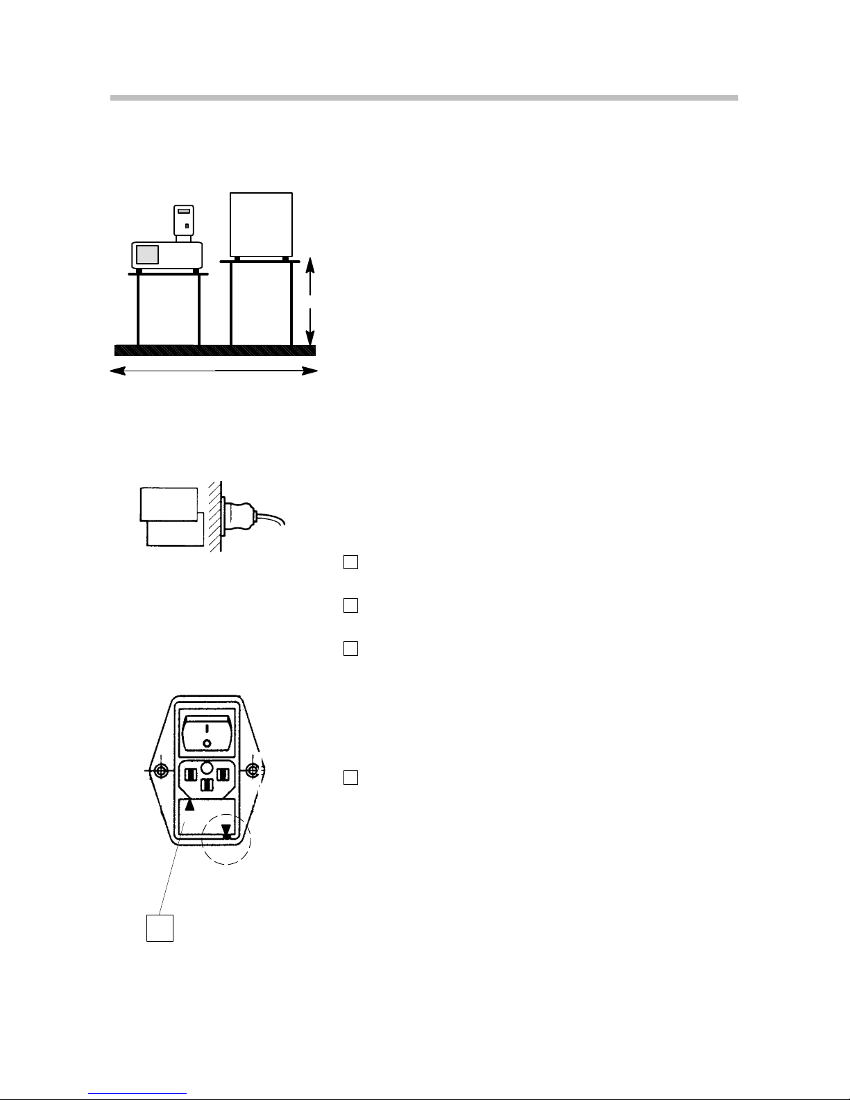
6.3 Space Requirements
Good working conditions for a complete installation require
an area of about 1 x 0.6 meters. The two benches should be
rigid with a level surface and easy to clean. The circulator
used for temperature control should be located below the
rheometer on a separate bench to avoid backflow of thermal
fluid and possible mechanical oscillation.
A suitable laboratory bench must be provided for
the installation.
The circulator has to be located below the level of
the rheometer, otherwise the thermal fluid flows
back in the cup holder and flushes the instrument.
6.4 Mains supply
Only attach the units to mains sockets with a
grounded earth. Compare the local mains voltage
with the specifications written on the name plates
of the measuring instrument and the control unit.
Voltage deviations of 10 % are permissible.
Mains cable and unit fuses:
1
Use the mains cable according to your local mains voltage ( see chapter “Contents of delivery”).
2
Insert the fuses according to your local mains voltage
below the mains connection 6.
3
For TCO, SHRP, TCL/Z, TCL/P:
230 V 2 x T1.6 A
100/115 V 2 x T3.15 A
For TCE/P, TCE/P, TCE/PC, TCP/P:
230 V 2 x T3.15 A
100/115 V 2 x T5A
4
Insertion of the fuses:
Pull out the fuse holder from the mains socket and
insert the fuses. Reinsert according to the marked voltage.
6.5 Cooling air for the measuring head
(HAAKE RotoVisco 1)
Compressed air is connected at nozzle 9 to avoid overheat-
ing under extreme load (high torque, high temperature
(200--350 C)) and at use of the measuring instrument at
temperatures > 100 C in the continuous operation respectively.
maximum conduction pressure 0.5 bar.
(RheoStress are cooled by the outgoing air of the air bearing.)
1.0 m
0.85
Rheometer
Circulator
Page 17

!
Unpacking / Ambient conditions
15
6.6 Requirements for the air supply
HAAKE RheoStress RS1 / RW1F
Pure air pressure is connected at nozzle for the air bearing
with a pressure by 2.5 bar (ideal way).
The air supply must have the following conditions:
-- max. 4 bar,
-- consumption approx. 10 dm3/minute
(1 dm3= 1 thousandth of a cubic meter),
-- no synthetic oil in the line,
-- max. oil contents 3mg/m3air,
-- dry air with a residual moisture < 40 %
Use the filter unit (order no. 222-1211) or the HAAKE
compressor (order no. 222-1434 for 230 V and 222-1435 for
115 V).
HAAKE RheoStress1: The pressure of the air supply for the
air bearing must not exceed 4 bar. Higher pressure will damage the air bearing permanently!
The air bearing reacts highly sensitive to dirt like particles (dust an
lint) or liquids (oil or water which condenses at high humidity levels). It is therefore recommended to have new air compressors run
for a longer period of time (0,5 hrs.) without actually connecting
it to the Rheometer. In the case of internal supply systems polluted
air might have collected near the connection nozzle when the line
has not been used for some time. Therefore, we also recommend
to ”flush” this line for a period of approx. 0.5 hrs.
6.7 Pipes in the building
Oil is generally applied to air pipes in the buildings of materialprocessing plants in order to prevent rusting in the workshops. By
means of complex filters the oil content may be reduced by rarely
so much that the air bearing does not suffer damage.
Thermo Fisher Scientific air bearings must not be used in plants in
which oil is added.
6.8 Air compressors
There are ”oil-free” and ”lubricated” versions of air compressors.
Only oil-free compressors (e.g. the HAAKE compressor) are admissible for Thermo Fisher Scientific air bearings.
If the hose length is larger then 5 m (between compressor and
measurement unit), it must be separately attached pressure controller located next to the measurement unit (see instruction
manual Air compressor Carat).
6.9 Ambient conditions according to EN 61010
It is recommended to run tests in an air-conditioned room,
(T = approx. 23 C):
indoors, max. 2000 meters above sea level,
ambient temperature 15 ... 40 C,
relative humidity max. 80%/31 C( 50%/40 C)
excess voltage category II, contamination level 2
Page 18

Unit Description
16
7. Unit Description
lntroduction
The viscoelastic behavior of a fluid or a soft solid can be characterized in two ways; either the fluid is deformed and the resulting stress is measured (CR mode), or the stress is applied and the deformation monitored (CS mode). The principle benefits of the CS mode are:
Software
Software control and evaluation with HAAKE RheoWin or
OS1 to program the display unit for production laboratories.
Measurements and evaluation
The Rheometers is controlled either by the HAAKE RheoWin Software or with one of 10 pre--programmable measuring procedures by the display unit. The results are available for further processing on a PC with the HAAKE RheoWin Software. Alternatively up to 50 measurements can be
stored internally and be evaluated, displayed or printed out
for documentation purposes.
Sensors
For HAAKE RotoVisco1 and HAAKE RheoStress1 plates,
cones, coaxial cylinders and immersion systems are available.
Page 19

Unit Description
17
7.1 HAAKE RotoVisco1
Thixotropy and flow curve
The determination of the flow behavior of a test substance
requires a speed ramp up, a holding time and a return curve
for the determination of the thixotropy. This hysteresis
method can like all other measuring procedures be PC controlled or can be loaded as procedure in the display and control unit.
Time curve
Is the viscosity of a test substance changing with time this
can be monitored objectively with the HAAKE RotoVisco1.
This is especially important for substances which are curing
(adhesives, building materials), change their viscosity with
storage time or show considerable changes of viscosity after
shearing during the production process (cosmetics, paint,
food).
Temperature programs
Temperature programs are very time consuming when the
rheometer has to be operated and supervised. With the RotoVisco1 these tasks can be taken over by the PC which controls t he rheometer as well as the temperature control units
-- everything without intervention of the operator.
Determination of the yield point
As soon as substances are strained beyond the Hookean
range they start to flow. This can be defined as yield point
and is an important characteristic value in quality control.
With the HAAKE RotoVisco1 this value can be established
relevant to practical applications, fast and easily by applying
a small deformation through extremely low speed values.
CD Mode
In the CD mode (speeds lower than 0.1 min
–1
) it is only measured at constant speeds. When ramps or steps are preset,
the following speed table is run:
Speed ( min
–1
)
0.0125
0.0250
0.0375
0.0500
0.0630
0.0750
0.0875
0.1000
Page 20

Unit Description
18
7.2 HAAKE RheoStress1
Flow curves
in CR and CS mode can be recorded as ramp or steps
(steady state).
Time curves
for reactions (e.g. curing) at constant temperature, shear
rate, shear stress or frequency.
Temperature programs
are software controlled to determine the temperature dependence with controlled shear stress, shear rate or frequency.
Yield points
can be determined with creep/recovery tests or with stress
controlled ramps.
Viscoelasticity
of a fluid can be quantified by a creep/recovery test or by dynamic measurements in CD (Controlled Deformation) or CS
(Controlled Stress) mode.
Multiwave
even allows the determination of the frequency spectra as a
function of time or temperature by overlay within shortest
time.
Page 21

!
Unit Description
19
7.3 Temperature control:
For applications at elevated temperatures above 250C
it is a must to switch the fan for the air bearing cooling
on stage 2 (on the rear) and use ceramic shafts only.
Furthermore use the cone heater TC1 as thermal shield
to prevent the heating up of the air bearing housing!
TCO Glass plate with a Pt100 temperature sensor
(not temperature controlled).
TCL/Z Liquid temperature controlled receptacle for cylinder
measuring systems with direct contact of the thermal
fluidfrom--40upto200C.
TCL/P Liquid temperature controlled measuring plate for
parallel plate or cone & plate measurements (with
external circulator from --20 up to 300C).
TCP/P Measuring plate with Peltier temperature control for
TCP/PE parallel plate or cone & plate measurements from
--40 up to 180C (external heat transfer required).
TCE/P Electrically temperature controlled measuring plate for
parallel plate or cone & plate measurements from
-- 2 0 Cupto350C.
TCE/PC Electrically temperature controlled measuring plate for
parallel plate or cone & plate measurements with
electrical cone heating from --40Cupto350C.
SHRP Special temperature controlled system utilizing
thermal liquid as standardized for asphalts and
bitumen.
Temperature range: 0C(--25C)... +90C
(for HAAKE RheoStress 1)
Page 22

Unit Description
20
7.4 Main features of the HAAKE rheometers:
Quick fitting sensor with a high precision even if not
perfectly clean.
Remote and manually controlled lift with variable
speed to preserve the fluid’s structure and ensure
reproducible test conditions.
Microprocessor controlled positioning of the sensor to
ensure the highest accuracy for routine tests.
Standard temperature range of --40 to 250 C using a
heating circulator; utilizing electrical cone heating
extends this up to 350 C.
Controlled rate mode for characterizing rheologically
complicated fluids (HAAKE RotoVisco 1 and HAAKE
RheoStress 1).
Controlled stress mode for characterizing sensitive
substances (HAAKE RheoStress1).
Forced oscillation tests at very low frequencies and
very low strains allow destruction free measurements
(HAAKE RheoStress 1).
Sophisticated application software packages with
userfriendly window menus and an on-line help key.
Page 23
Installation
21
8. Installation
8.1 Setting up the Rheometer
Lift the Rheometer out of the package and place onto a
stable, level table. Do not lift the unit at the glass pane or
at the measuring head ! For sensible measurements a
plane table is recommended.
In the base of the measuring instrument, there are four feet
which can be screwed in or out for levelling the unit.Upon
completion of the preliminary visual levelling, exact precision
levelling can be carried out using the spirit level supplied.
1
The spirit level:
is put on the measuring plate at temperature control
unitTCL/P;TCE/P;TCE/PCandTCP/P.
is put into connection with a vessel at temperature con-
trol unit TCL/Z.
is put on the measuring plate in the vessel at tempera-
ture control unit SHRP.
is not used at temperature control unit TCO.
2
Adjust the feet so that the air bubbles remain in the center of the spirit level.
This adjustment process should be repeated at least once a
week.
Page 24
!
Installation
22
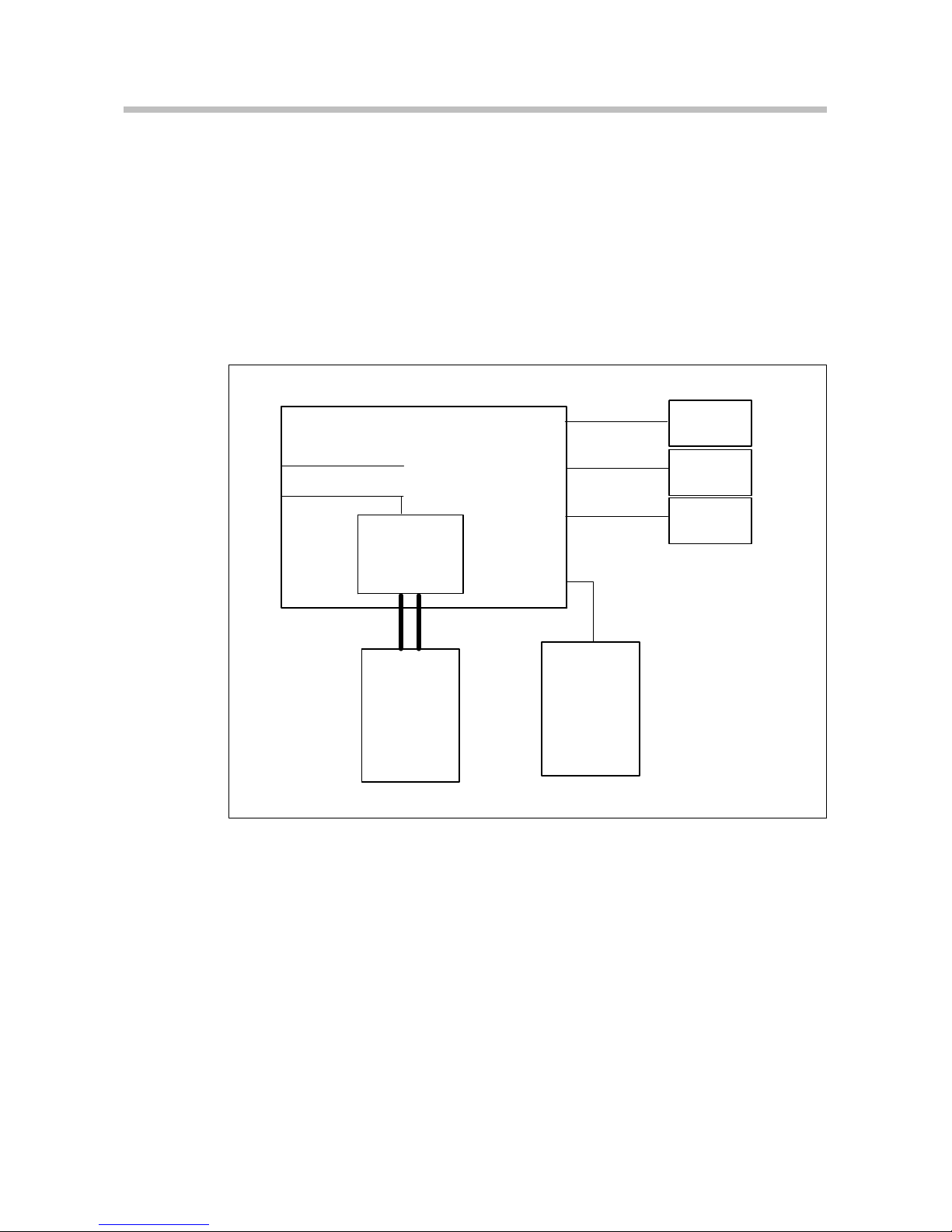
8.2 Connecting up
Make sure that the unit has been switched off before you connect or disconnect the cables.
The cable connections between the sensor system, the control unit, the PC and the printer have to be established
( see. chapter Pin Wiring)
Measuring
Instrument
PC
Air
supply
unit
Heating
Bath
and
Circulator
Control
unit
Printer
and/or
Temperature
Control Units
RS 232
Centronics
Display
Luft / Air
PT100 ( output )
PT100 ( input )
Shielded RS232 cable with ferrite core
e.g.
filter unit 222-1211
or
compressor 222-1435
(RheoStress 1)
222-1490
222-0572
8.2.1 PT100 connection
PT100 (input) socket for external PT100 sensor only
when using TCO
PT100 (output) socket for PT100 sensor only when using
TCL/Z and TCL/P
The connections are described in chapter “Pin Wiring”.
Page 25

!
!
Installation
23
8.3 Hose connections
8.3.1 Temperature control unit (with liquid):
The temperature control unit with liquid temperature
control is connected with hoses to a heating bath and
circulator.
While fastening the hose connections at the connecting nozzles (14) of the temperature control unit
the connecting nozzles must be held up by
wrenches.
Direction of flow of the liquid
Temperature range up to 150 C:
Viton hoses
Hoes nozzle -Set 222--1492
Temperature range of 100 Cupto350 C:
Metal hoses 333-0294
Hoes nozzle -Set 222--1492
Liquid temperature control:
Temperature range up to 100 C:
Thermal liquid in the temperature range between --50
C and 30 C: water with anti-freeze.
Temperature range from 5 Cto90 C: distilled water.
Distilled water
Normal mains water causes cable deposits and
frequently requires the unit to be descaled.
In principle, water up to 95 C can be used. However,
above 80 C, so much water evaporates that it requires
frequent topping--up.
Water with anti--freeze
If you intend working at temperatures below 5 C,
anti--freeze must be added to the water. The added
amount of anti--freeze should be sufficient for a
temperature that is about 10C lower than the intended
working temperature. This prevents the freezing of
water on the evaporator coil of the cooling circuit, the
surface of which is always much colder than the
Page 26

Installation
24
working temperature. However, too much anti--freeze
worsens the temperature constancy due to its high
viscosity.
Temperature range from 100 Cto200 C:
Silicone oils or other suitable liquids are used as thermal liquid.
8.3.2 Air bearing (measuring unit)
The air bearings of the measuring units HAAKE
RheoStress1 require cooling air at port 9
(see “Requirements for the air supply”).
Page 27

Functional Elements
25
9. Functional Elements
9.1 Temperature control units
Rheometer Temperature control units
TCO TCL/Z TCL/P TCE/P
TCE/PC
TCP/P SHRP
HAAKE RotoVisco1 X X X X X
HAAKE RheoStress1 X X X X X X
Page 28

Functional Elements
26
9.2 External filter
An external filter is part of the standard range of items
supplied with the temperature control units for Series 1
TCP/P (Peltier-Temperature control system), TCE/P
(electrical temperature control unit), TCL/PO (liquid
temperature control unit for HAAKE RheoScope) and the
UTCP/P (Peltier-Temperature control system for HAAKE
RSXXX units). It consists of the filter itself, a plastic cone
contained inside it, and clamps.
Using this filter enables the interior of the relevant
temperature control unit to be protected against any
impurities carried in by the temperature liquid. The external
filter represents an additional protection. On the standard
model a sieve is built in to the intake of each temperature
control unit.
As shown in Fig. X, the filter is installed in the intake hose
leading into the temperature control unit between the
thermostat and the measurement instrument. The intake
and outlet directions must be noted (IN and OUT on the
filter). It is fastened with the clamps that are supplied with it.
Hoses with a diameter of 8 mm can be installed and fastened
with the clamps supplied. The plastic cone on the inside of
the filter serves as a direction of flow indicator, and its
movements show the through-flow of the tempering liquid. If
there are impurities in the filter it can be taken out, cleaned,
and used again. The use of the external filter is
recommended because any impurities can be recognised
and removed more readily than with the sieve that is built in
to the temperature control unit. The screw-in sieve (internal)
must of course be checked for impurities from time to time
in order to ensure t he functional capability of the temperature
control unit.
Order numbers:
003-5266 Screw-in sieve (internal) for TCL/P, TCP/P,
TCE/P, TCL/Z
222-1667 External filter for TCP/P, TCE/P, TCL/PO
Page 29
Functional Elements
27
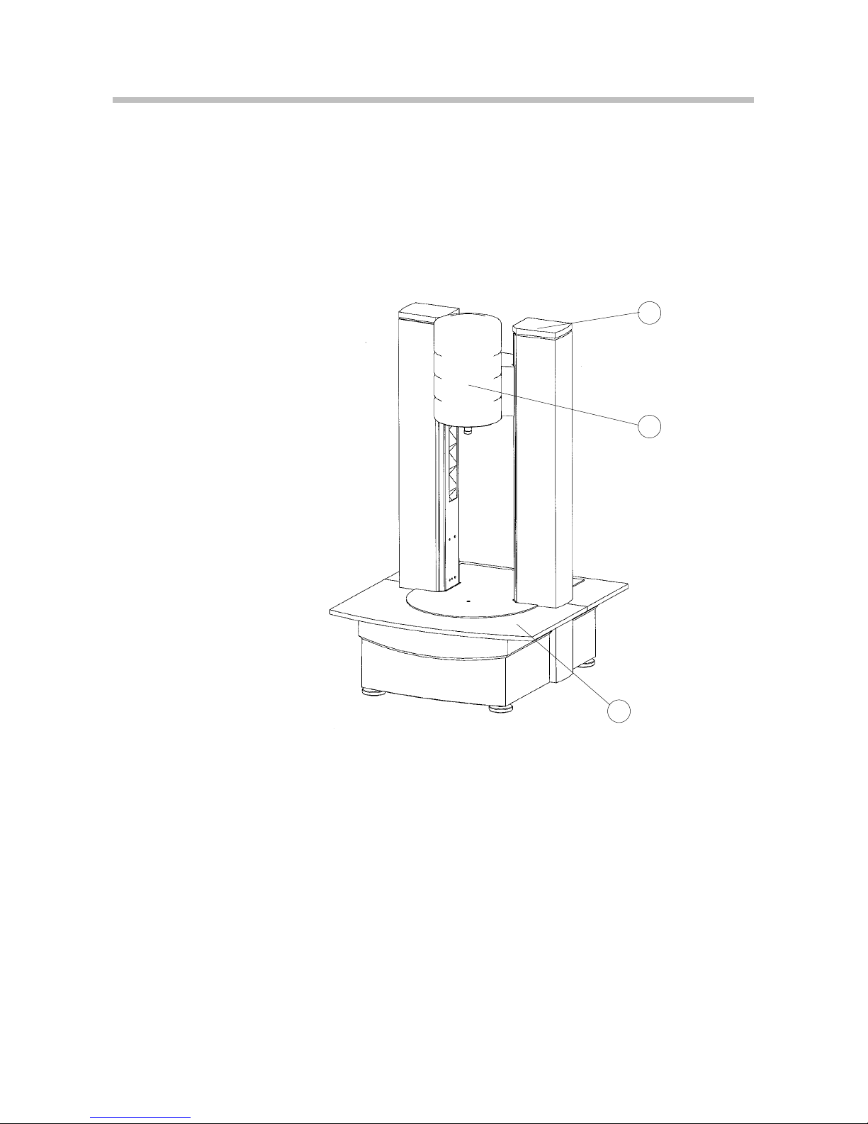
9.3 Measuring Instrument with no
temperature control unit.
Front
1
4
3
1. Measuring unit
3. Quick cut-off switch
4. Green LED display: operational
Page 30

Functional Elements
28
Rear
6
12
13
11
7
8
10
A
9
A. Caution: Read the instruction manual
6. Mains switch with mains socket and fuses
7. RS 232 interface (PC)
8. Connection for printer
9. Connection for cooling air
(RheoStress1 for the air bearing)
10. PT 100 Connection
11. Connection for display unit
12. Reset switch
13. Switch for bootstrap loader
Page 31

!
Functional Elements
29
9.4 Measuring Instrument with
TCL/Z -- temperature control unit.
Front
3
1
2
4
5
18
A
A. Caution: Read the instruction manual
Glass pane can heat up!
Use safety gloves!
1. Measuring unit
2. Temperature control unit
3. Quick cut-off switch
4. Green LED display: operational
5. Yellow LED display: heating
18. Clamping lever
When using a circulator for temperature control,
this must be located lower than the measuring device, other via the temperature control liquid will
flow back in to the measuring beaker location and
over the measuring device.
Page 32

Functional Elements
30
Rear
14
6
12
13
20
11
7
8
9
14
IN OUT
A. Caution: Read the instruction manual
6. Mains switch with mains socket and fuses
7. RS 232 interface (PC)
8. Connection for printer
9. Connection for cooling air
(RheoStress1 for the air bearing)
11. Connection for display unit
12. Reset switch
13. Switch for bootstrap loader
14. Liquid cooling for temperature control unit
20. Connection for PT100 (output)
Page 33

Functional Elements
31
9.5 Measuring Instrument with
TCL/P / TCE/P / TCP/P / TCP/PE
-- temperature control unit.
Front
3
1
2
4
5
19
A
A. Caution: Read the instruction manual
Glass pane can heat up!
Use safety gloves!
1. Measuring unit
2. Temperature control unit
3. Quick cut-off switch
4. Green LED display: operational
5. Yellow LED display: heating
19. Measuring plate
Page 34

Functional Elements
32
Rear
OUT IN
14
6
12
13
11
7
8
9
A
20
A. Caution: Read the instruction manual
6. Mains switch with mains socket and fuses
7. RS 232 interface (PC)
8. Connection for printer
9. Connection for cooling air
(RheoStress1 for the air bearing)
11. Connection for display unit
12. Reset switch
13. Switch for bootstrap loader
14. Liuid cooling for temperature control unit
20. Connection for PT100 (output) only at TCL/P
Page 35

Functional Elements
33
9.6 Measuring unit with TCE/PC-temperature
stabilisation unit and cone heater TC1
Front side
3
1
2
4
5
19
A
21
A. Caution: Read the operating instructions!
Unit parts can get hot!
Wear protective gloves!
1. Measuring unit
2. Temperature stabilisation unit
3. Emergency OFF switch
4. Green LED: Ready for operation
5. Yellow LED: Heating
19. Measuring plate
21. Cone heater TC1
Page 36

Functional Elements
34
Rear
OUT IN
14
6
12
13
11
7
8
9
A
20
22
23
24
2
5
A. Caution: Read the operating instructions!
6. Mains switch with mains socket and fuses
7. RS 232 interface (PC)
8. Connection for printer (Centronics)
9. Connection for cooling air
(RheoStress1 for the air bearing)
11. Connection for display unit
12. Reset switch
13. Switch for bootstrap loader
14. Liuid cooling for temperature control unit
20. Connection for PT100 (output)
22. Fuse T1.25A
23. Fuse T8.0A
24. Fuse T3.15A
25. Connection for cooling air (for TC1)
Page 37

!
Functional Elements
35
9.7 Measuring Instrument with
SHRP -- temperature control unit.
Front
3
1
2
4
5
17
A
A. Caution: Read the instruction manual
Glass pane can heat up!
Use safety gloves!
1. Measuring unit
2. Temperature control unit
3. Quick cut-off switch
4. Green LED display: operational
5. Yellow LED display: heating
17. Influx control
When using a circulator for temperature control,
this must be located lower than the measuring device, other via the temperature control liquid will
flow back in to the measuring beaker location and
over the measuring device.
Page 38

Functional Elements
36
Rear
14
6
12
13
11
7
8
9
14
16
A
A. Caution: Read the instruction manual
6. Mains switch with mains socket and fuses
7. RS 232 interface (PC)
8. Connection for printer
9. Connection for cooling air
(RheoStress1 for the air bearing)
11. Connection for display unit
12. Reset switch
13. Switch for bootstrap loader
14. Liquid cooling for temperature control unit
16. Overflow port
Page 39

down
up
MenuEnter
Tast e 4Tast e 1
Tast e 2
Tast e 3
Tast e 5
Tast e 6
Nr.(HEADER)
(Status)
Functional Elements
37
9.8 Display unit (optional)
(Order no. 222--1472)
DOWN
UP
MENÜ
ENTER
Tas t e 4
Tas t e 1
Tas t e 2
Tas t e 3
Tas t e 5
Tas t e 6
Nr.MENÜ
Status
General display screen splitting
Header gives the display title
see mask number on the right;
Keys1to6 are reserved differently under each display
title
Up/Down increase or decrease e.g. number values;
short pressing - small increments,
long pressing - increasingly higher
increments;
Enter is the confirmation of an entry or selection;
Menu goes back to an overview display;
Status shows date/time, internal store capacity
for measurements, help texts
Page 40

Functional Elements
38
9.9 Menu tree of the display unit
Page 41

Menu
Temp. controlDiagnosis
Time / Date
Display
Language
Lift
100CONFIGURATION
OperatorConfiguration
Jobs
Lift
Sample name
010MENU
Status
OperatorConfiguration
Jobs
Lift
Sample name
010MENU
Status
Status
!
!
Operating
39
10. Operating
10.1 Switching on
1
When all connections have been established and the
supply lines are active, switch--on the mains switch 6:
The green display 4 on the measuring table of the
rheometer indicates the ready state for operation.
The following operation sequence should be used to be able
to make the measurements at short notice:
-- Instrument:
Automatic device initialization
Raises the lift. Never switch off the unit during lift move-
ment.
In case of loss of power during the lift movement,
the unit has to be initialized again.
Then the following display appears:
-- Operator: Insert sensor if necessary
-- Instrument: Lowers the lift for zero point determination.
Due to the rotation of the pin spots can appear on
the measuring plate. This is normal and does not
constitute any damage to the unit.
Then move the lift again to cleaning position (i.e. up), the instrument immediately shows the MENU selection window
(A) for defining, if necessary,the operator, sample name etc.
10.2 Working with the display unit
In MENU activate CONFIGURATION by pressing the key.
Pressing the key leads directly into the submenu.
Page 42

Menu
Full
Print
200DIAGNOSIS
Status
Menu
203DATA MEMORY
Status
Start
Change
Change
Menu
Cancel
Date: xx xx xxxx
Time: yy:yy:yy
201TIME /DATE
Status
Menu
Online displayContrast
Units
Country
Online graph
202DISPLAY
Status
Enter
Operating
40
Diagnosis
FULL-DIAGNOSIS:
-- The complete device diagnosis contains all internal tests
which are possible at present;
HARDCOPY:
-- Sends a diagnosis report to the printer.
Date / Time
Display
Pressing each key leads directly into the respective submenu:
CONTRAST
Contrast number: xx increase or decrease
UNITS
Switch over facility for
Temperature: Cor F
Viscosity: Pas or mPas
COUNTRY SETTINGS
Choice of one of two available date formats.
ON-LINE-VALUES
ONE predefined display mask with 6 fields (3x large fields on
left and 3x small fields on right, respectively assigned to the
keys) appears. On pressing a key at the respective field, this
field is activated and any desired physical parameter can be
assigned to it.
Fields with no parameter assigned to them do not appear
during the measurement.
ON-LINE-GRAPHICS
Twoy--axes and one x--axis can here be assigned to any desired respective physical parameters.
Data memory
Page 43

Menu
SpanishGerman
English
French
204LANGUAGE
Status
More
OperatorConfiguration
Jobs
Lift
Sample name
110MENU
Status
Batch ID
Menu
Open
Together
Stop
110LIFT
Status
Contact
Measurement
Sensor
Operating
41
Language
Measure
The measurement sequence as a whole is described under
”Measuring sequence”.
Lift
LIFT activation takes place in MENU by pressing the key.
Pressing the key leads directly into the submenu:
OPEN
-- The lift raises to t he top position and stops there
(cleaning position).
CONTACT
-- The lift moves down to t he contact point (zero point)
-- and then up again to the cleaning position with status
message reporting successful zero point determination.
TOGETHER
-- The lift runs max. (if STOP is not actuated before) to
the contact point and stops there.
STOP
-- Stops the lift immediately.
MEASURING POSITION
-- Runs from the current position (usually the cleaning
position) to the measuring position.
Page 44

More
OperatorConfiguration
Jobs
Lift
Sample name
010MENU
Status
Batch ID
Menu
SchleimTei g #1
Teig #2
PE-Lösung
More
010SAMPLE NAME
Status
More
OperatorConfiguration
Jobs
Lift
Sample name
Batch ID
010MENU
Status
More
Muster
115OPERATOR
Status
Menu
Operating
42
Operator
In MENU activate OPERATOR by pressing the key.
Pressing the key leads directly into the submenu:
-- The list of OPERATORs is defined in RheoWin and downloaded from there.
Sample name
In MENU activate SAMPLE NAME by pressing the key.
Pressing the key leads directly into the submenu:
-- The list of SAMPLE NAMEs is defined in RheoWin and
downloaded from there.
Page 45

More
OperatorConfiguration
Jobs
Lift
Sample name
Batch ID
010MENU
Status
More
Polyethyl. CreepSnap-shot test
Manual Measurement
Multiwave
Linearitätstest
105JOBS
Status
Aushärtungstest
Menu
SampleMethode:
Sensor:
Multiwave:
210MEASUREMENT DEFINITION
Status
125BATCH ID
Status
More
OperatorConfiguration
Jobs
Lift
Sample name
Batch ID
010MENU
Status
ID: ABC87--D2/F
ABCDEFGHIJKL MNOPQRSTUVW
up
down
Menu
MenuÜbersicht ausdrucken
Batch ID:
Sample number
Start test
Operating
43
Batch ID
In MENU activate BATCH ID by pressing the key.
Pressing the key leads directly into the submenu:
-- Batch ID must be entered on the display unit.
Measuring sequence
In MENU activate MEASURE by pressing the key.
Pressing the key leads directly into the submenu:
(The names of the jobs are defined by the user in the RheoWin--Software.)
”Snap--Shot Test” and ”Manual measurement” are permanently assigned.
Pressing a key leads directly to the ”Measurement definition
screen”.
-- If all specifications are correct, the operator can press
”START TEST”.
Page 46

Stop JOB
Stop element
320TEST RUN
Status
Start test
Menu
321TEST STOP
Status
Lift
Operating
44
-- After the operator has started the measurement, the job
starts and the display shows the predefined online form.
-- The operator waits until the job is completed or discontinues the job or the current element (jumps to the next element).
On completion or discontinuation of the job, the following display appears:
The operator sees the results of the job on the display and
has 3 options for continuing:
1
Insert new sample: Press LIFT (lower lift), display No.
110 appears, replace old sample with new one and
then continue.
2
Next measurement (same job) with same sample but
possibly other parameters:
Press STARTNEW MEASUREMENT. Any existing parameter place holders of this job are shown again for
editing.
3
General continuation of operation of the instrument via
MENU.
Page 47

Operating
45
10.3 Starting the software
1
Switch on the PC and load MS Windows.
2
In the Windows Program Manager double-click t he
RheoWin Job Manager icon.
RheoWin is started.
3
Click the Device Manager icon in the menu bar.
4
Select the connected unit in the Device Manager and
check the connection with ”Test”.
For extensive operation please read the instruction
manual of your software.
Page 48

Operating
46
10.4 The ”Upload Mode” for the Display Unit
(RheoWin 2.6 or higher)
The rheometers can be operated by the software RheoWin
in ”direct mode” or it can be loaded by special functions measuring programs in the store of the measuring device. By
that, the measuring device gets independent of the PC and
it is only connected for programming or data transfer. The
measuring programs (”JOBs”) are started after the corresponding programming with the display unit.
For programming or data transfer the Rheometer must be
connected to the PC via RS232 cable as usual and Thermo
Fisher Scientific Haake software RheoWin must be loaded.
After installing the rheometer two versions per model can be
found in the device manager . The device e.g. RotoVisco1
is running in the software direct mode as usual. Model RV1
(Upload mode) has already been pre--defined as independent device.
The characteristic ”Upload Mode” is transferred to the device
driver on the following card which can be found under ”Edit”.
So you can give the device driver the characteristic ”Upload”
or ”Software” mode. For practical reason it is advisable to define a new device for each operation.
Page 49

Operating
47
Other options on the device record card are:
Torque Compensation
When the torque compensation is activated, the present
value of the torque display is set on zero ”0” right before the
measurement so that possible faults (offset faults) can be reduced. This is always advisable when samples without ”yield
point” are to be measured. In case of doubt it is measured
first without ”Torque Compensation” and after that it is decided whether the function can be used.
Inertia of Masses Correction Ramp
If fast speed ramps (< 180 s) are driven, the dampening set
at the sensors (usually 30%) and also the inertia of the
masses of the measuring device (motor and rotor) enter the
result. Fast ramp speeds make up a hysteresis curve which
does not come from the sample but from the test conditions
and the measuring device. The influence can be seen qualitatively in the following diagram. It is recommended to drive
measurements with ramp times of less than 120s without
correction only in special cases. With correction, the influences of the inertia of masses are compensated. This can
be tested individually at examples relating to practice.
Page 50

Operating
48
Communication Record
This function has been installed for service use. If this function is activated, all commands between the measuring device and the PC are recorded in a file named Driver.log
(RV1.log, RS1.log,) and are managed in the directory \rheo-
win\driver\.
Upload
Under ”Upload” you can find the present data for user, sample and sensor. These data are entered with RheoWin and
are read out . In the display unit these exact terms can be selected. If you are connected to the measuring device at the
running time the present level of the store is read out with
”READ” and is displayed. Changes can be made. They are
transferred to the measuring device while leaving the menu
and are available now. If the device has not been programmed yet (state at delivery) all lists are empty.
Now the three record cards can be filled with information.
With the mouse and the cursor the first position is clicked and
e.g. a name is entered. After that the second line can be
clicked and other entries can be made.
Page 51

Operating
49
When all names of possible users are entered, the names of
the samples which are to be measured can be entered. Only
these names can be recalled from a selection list.
In principle the same is valid for the sensors of the rheometer. It is recommended to enter only the sensors which are
really in existence from the list of all variants to keep the display clearly organized.
Page 52

Operating
50
The sensors of the right window are transferred to the measuring device if you leave the menu with <OK> . With Cancel
the existing adjustments are kept. If the factors are changed,
e.g. after a calibration, the values of the sensors can be renewed with <READ> after the reading of the store.
Drawing up JOBS for Uploading
JOBs or measuring and evaluation procedures are drawn up
with the RheoWin Job manager. The distinction takes place
before the drawing up of a JOB at the selection of the measuring device. If existing JOBs are changed afterwards unexpected reactions can take place. The following proceeding is recommended:
First the measuring device is selected. After that the procedure is drawn up.
Page 53

Operating
51
After the selection of the measuring device, the sensor and
a temperature control unit are selected. If no temperature
control unit is selected, no temperature control can take
place. No selection (--------)also means that the temperature
control unit is switched off.
The measuring process is now composed according to the
requirements of the application or of the user just as in the
PC mode. There are some restrictions of the length of names
and the selection of elements. These restrictions are visible
only at editing.
After the drawing up of a JOB it can directly be started for a
test or it can be uploaded to the measuring device. On this
Page 54

Operating
52
occasion a list gets visible that shows an empty list or already
existing JOBs. The order or position of the list corresponds
to the reservation in the measuring device. So you can make
an allocation indirectly. Empty positions have to be avoided,
because otherwise the following entries would be ignored.
Uploaded JOBs can be called in via the display unit and can
be carried out directly.
Reading back uploaded JOBs from the measuring device
JOB’s can be read back from the measuring device with the
RheoWin function /File/Open Job of Measuring Device/.
This function corresponds to the reading of the hard disk.
If this function is selected, all installed unit drivers are called
in and it is tested if a connection can be made. Drivers that
are not installed correctly cause error messages and should
be cancelled from the device list (device manager). If a measuring device with the possibility of managing JOBs responds it is selected and displayed immediately.
Page 55

Operating
53
In the white area the existing JOBs are listed for selection.
Measuring result
The measuring result is a chart with measuring and preset
values according to the measuring definition. It can be transferred, if defined in the JOB, directly to a printer. The result
is then shown as selected. Segments can be printed or ignored. The selection of the column contents takes place via
the list menus:
Importing the measuring result in RheoWin
The last measuring result can also be imported directly to the
RheoWin software (measuring device connected to PC and
RheoWin active).For this the file in the DATA manager is
opened.
Page 56

Operating
54
From the following list the device of your choice is selected
for reading out the data. This is necessary because the software RheoWin can drive and read several units by multitasking.
After the selection the data are transferred via RS232 interface from the measuring device to the PC/RheoWin software. The data are treated like comparable values of the local hard disc or of the network.
Page 57

Operating
55
10.5 Quick Cut-off
The switch (3) at the top of the right column switches off the
measuring drive, heating and lift.
Internal measuring jobs are interrupted.
Page 58

Temperature Control Units
56
11. Temperature control units
11.1 Temperature control unit TCO
The sample is in the measuring gap of the sensor system.
The rotator is driven by a preset speed (n). Due to its viscosity, the sample is resistant against the rotation. This resistance gets active as (braking) torque (Md) at the measuring
shaft of RV1. The torque is measured.
From the values of speed, torque and measuring system geometry (system factor) the installed PC calculates the the
measuring values for
If a temperature sensor is connected, the temperature T (in
C) is also calculated.
The results are shown on the display (operating panel) and
and can be passed on to a computer (PC) or printer via interface connection RS232.
Page 59

open
closed
!
!
Temperature Control Units
57
11.2 Temperature control unit TCL/Z
Place the beaker into the temperature control unit and fix it
with the clamping lever.
The sensor system and the temperature control unit require
cooling according to load and temperature during the measurement.
Connect the rheometer to a Thermo Fisher Scientific Haake
circulator with optional hoses ( 8 mm).
While fastening the hose connections at the connecting nozzles(14) of the temperature control
unit::
-- ensure the correct flow direction (IN/OUT)
-- the connecting nozzles must be held secured
using a wrench.
maximum conduction pressure 0.5 bar (water circulation).
For the TCL/Z sensor system and the open--bath and heat-
ing circulators the necessary tubing hoses are not part of the
standard accessories. They have to be ordered separately.
When the measuring beaker is inserted in the t emperature control unit, a valve is automatically opened as it is
pressed in and temperature control liquid flushes the
beaker. The valve is closed again when the beaker is
removed.
The displacement path of the valve means that the
beaker must be moved 3mm. If the seal is missing or an
incorrect closing screw has been fitted, the valve can
remain closed and the temperature control function is
inoperative.
Remedy:
Fit a new seal, a correct closing screw or a
spacer.
The circulator must be located lower than the measuring device, other via the temperature control
liquid will flow back in to the measuring beaker
location and over the measuring device.
For the TCL/Z measuring unit and the open--bath and heating circulators the necessary tubing hoses are not part of the
standard accessories. They have to be ordered separately.
The lever (222--1639) for cylinders is an accessory for t he
RheoStress 1 and RotoVisco 1 rheometer models, which are
equipped with a liquid temperature control unit (TCL/Z) for
coaxial cylinder measuring geometries.
The lever enables the removal of the measuring cup, e.g. for
cleaning at the end of a measurement.
Page 60

Temperature Control Units
58
The following procedure is recommended:
1
Switch the circulator off, in order to reduce the low pressure of the temperature liquid.
2
Position the lever as illustrated in Fig. and move the lever upwards till the measuring cup is free to move.
3
The measuring cup can be now easily removed by
hand.
Hendling of the lever
lever
measuring cup
Page 61

!
Temperature Control Units
59
11.3 Temperature control unit TCL/P
The temperature control unit has a holding for the measuring
plate. The measuring plate is put on the thermal liquid heated
temperature control unit and is fastened.
Cones and measuring plates should have the same diameter e.g. as cone C60/1 and the measuring plate MP60 or
plate PP35 and measuring plate MP35. If not, huge measuring faults are the consequence !
For measurements at temperatures higher than 70Citis
recommendable to use at least the sample protection shield
(222-0608) to reduce the loss of heat. In any case, the application of measuring cones and measuring plates with a
ceramic shaft that do carry off less heat is recommendable.
The sensor system and the temperature control unit need
cooling that is dependent on the load and the temperatures
during the measurement.
While fastening the hose connections at the connecting nozzles(14) of the temperature control
unit::
-- ensure the correct flow direction (IN/OUT)
-- the connecting nozzles must be held secured
using a wrench.
For the cooling of the temperature control unit hoses (with
8mm) can be connected to a liquid circulator.
maximum conduction pressure 0.5bar (water circulation).
Page 62

!
Temperature Control Units
60
11.4 Temperature control unit TCE/P
The temperature control unit has holding a for the measuring
plate. The measuring plate is put on the thermal liquid heated
temperature control unit and is fastened.
Cones and measuring plates should have the same diameter e.g. as cone C60/1 and the measuring plate MPC60 or
plate PP35 and measuring plate MPC35. If not, huge measuring faults are the consequence !
For measurements at temperatures higher than 80Citis
recommendable to use at least the sample protection shield
(222-0608) to reduce the loss of heat. In any case, the application of measuring cones and measuring plates with a
ceramic shaft that do carry off less heat is recommendable.
The temperature control unit is connected to a liquid circulator via hoses ( 8mm) .
For the TCE/P measuring unit and the open--bath and heating circulators the necessary tubing hoses are not part of the
standard accessories. They have to be ordered separately.
The cooling (liquid or gas) is controlled directly in
the measuring device via the built-in solenoid
valve according to the requirements. It is important
that the cooling medium used is selected in the
RheoWin software, as the control parameters (PID)
are thus selected.
The switching condition of the valve is „open“.
Utilizing the optional electrical cone heating extends the
temperature range up to 350C.
Page 63

Temperature Control Units
61
11.5 Temperature control unit TCP/P and TCP/PE
The temperature control unit has a measuring plate 60,
which is at the same time the location for other measuring
plates. The measuring plate is put on the Peltier temperature
control unit and fastened.
The additional plates MPC are only necessary if the same
cone--plate diameter is used for measuring.
Temperature control is carried out electrically via a Peltier
element within a temperature range of --40 to 180C.
The Peltier process
The temperature control system is based on a component
which uses the Peltier effect. This effect which is the reverse
of the thermoelectric effect (e.g. used by thermocouples),
was discovered in 1834 by the French physicist Jean Peltier.
Peltier elements consist of two semiconductor bridges of differing doping (p- and n-type). Stimulated by a (regulated direct-)current flow, the electrons transport heat from one connection point to the next.
Diagram of a
Peltier module
n- and p-doped elements
contact bridges
electric insulation
Cold side
Hot side
The heat flow direction is dependent on the current flow
direction. Peltier temperature control systems can thus be
used for both heating and cooling depending on the current
flow direction.
The heating or cooling capacity i.e. the transported heat
quantity is proportional to the current strength depending on
the semiconductor material used and the number of Peltier
elements electrically connected in series within the Peltier
module.
Page 64

!
!
!
Temperature Control Units
62
Peltier modules transport heat from one side of the module
to the other and thus can be understood as the thermoelectric system of a solid state heat pump. Heat itself is scarcely
absorbed during this process. The heat side is in any case
exposed to the dissipated energy in addition to the transported Peltier heat which has the result of causing the heating and cooling measuring curves not to be identical. The
maximum heating rate is therefore higher than the maximum
cooling rate.
Operation
In the temperature control unit a cooling coil (with hose connections for liquid cooling) is built in to cool the Peltier element.
The connector nozzles of the heat exchanger may
not be closed during operation. A high overpressure may exist during the heating up.
The temperature control plate is set in a plastic part (TEKAPEEK).
Recommended couling liquids are water or
mixtures of water / alcohol as well as water / glycol.
The maximum for the temperature of the couling
liquid is 100 C.
Cooling and Heating
Since the Peltier temperature control unit is cooled by circulating water the temperatures as well as the heating and
cooling rates (times to reach t hose temperatures) depend on
the temperature and of the flow through rate of the coolant.
By variation of the flow-through temperature and the flowthrough volume optimum conditions can be reached for
every working range desired.
In general, the following applies:
During heating the temperature control unit will reach
a max. temperature difference of abt. 100C between
temperature control plate and the temperature of the
coolant under optimum conditions.
During cooling the temperature control unit will reach
a max. temperature difference of abt. 20--40C
between temperature control plate and the temperature of the coolant under optimum conditions.
Page 65

Temperature Control Units
63
Heating
1
2
3
20
140
Final temp.
[ C]
600
t[s]
1
2
3
Cooling curve with water circulator
(DC50--K20) of about 80C
Cooling curve with high temperature supply of about 100C
Cooling curve with room temperature
coolant fluid
80
In general, the following applies for the heating:
Increasing the temperature of the coolant will result in
higher final temperatures and higher heating rates (the
final temperature will be reached faster).
Decreasing the flow through volume will result in higher
final temperatures and higher heating rates.
Example:
With a preset temperature of 20C the Thermo Fisher
Scientific Haake circulator DC50-K20 will reach max. heating
rates up to 1 K/s and a final temperature of about 100C after
about 10 minutes.
Page 66

Temperature Control Units
64
Cooling
Cooling curve with high temperature of
the coolant (room temperature)
Cooling curve with coolant water circulator
(DC50--K20) (reservoir temperature 20C)
1
2
20
360
t[s]
3
Final temp.
[ C]
0
1
2
3
Cooling curve with low temperature of the
coolant (reservoir temperature 5C)
-- 2 0
10
In general, the following applies for the cooling:
Decreasing the temperature of the coolant will result in
lower final temperatures and higher cooling rates (the
final temperature will be reached faster).
Increasing the flow through volume will result in lower
final temperatures and higher cooling rates.
Example:
With a preset temperature of 20C at the Thermo Fisher
Scientific Haake circulator DC50--K20, the Peltier system will
reach max. cooling rates up to 1 K/s and a final temperature
of 0C. Starting at +20C the final temperature of 0C will
be reached after about 6 minutes.
For a given ambient or room temperature there is a low-
est temperature which can be reached. This is usually
about 0C.
lower temperature values can be realized if the loss of
cooling capacity is reduced by insulation.
Page 67

Temperature Control Units
65
Explanation for the cooling
The cooling rate is limited especially for a value when cooling
below the ambient temperature. Therefore, the settings of
the software have to be adapted in order to reach the temperature desired:
1. For the measuring definition of temperature ramps
downwards the ”rising” will be tested -- for cooling negatively. That means that it has to be calculated according to the set values for start and end temperature as
well as the duration using a formula to find out whether
the cooling rate can be achieved. If it is not possible an
error message shows the possible cooling rate.
2. At the beginning of a segment cooling down to the set
starting temperature can be necessary. This coolingdown time will be calculated. In case the time being
higher that 10 s the band width will be set from 0.0 to
0.1 to reach the desired start temperature. In this case
a message window appears as always whenever the
band width for the start temperature is unequal 0.0. The
system waits until the band width of 0.1 has been
reached.
Attention: An abortion using the F7 key would also
abort the cooling process. Then the segment would be
measured with the temperature reached until then.
3. For temperature segments the waiting time set by the
user might be too short to hold the possible cooling
rate. In case the time being more than 10 s too short it
will be set to the required value.
The sensor system and the temperature control unit require
cooling that is dependent on the load and the temperatures
during the measurement.
Page 68

!
Temperature Control Units
66
For the cooling of the temperature control unit hoses (with
8mm) can be connected to a liquid circulator.
While fastening the hose connections at the connecting nozzles(14) of the temperature control
unit::
-- ensure the correct flow direction (IN/OUT)
-- the connecting nozzles must be held secured
using a wrench.
maximum conduction pressure 0.5bar (water circulation).
For the TCP/P measuring unit and the open--bath and heat-
ing circulators the required tubing hoses are not part of the
standard accessories. They have to be ordered separately.
Page 69

!
Temperature Control Units
67
11.6 Temperature stabilisation unit TCE/P with
cone heater TC1
The temperature stabilisation unit has a holder for the measuring plate. The measuring plate is placed and secured
onto the electrically heated temperature stabilisation unit.
The wedge and measuring plates should have the same diameter, for example like the taper C60/1 with the measuring
plate attachment MPC60 and the plate PP35 with the measuring plate attachment MPC35. Otherwise unavoidable
measuring errors arise!
11.7 Cone heater TC1
The high temperature system TC1 was developed for the
measuring units with a TCE/P temperature stabilisation unit
for rheological measurements at temperatures of > 0Cto
350C with and without external cooling. Inert gas should be
used for cooling.
A PID controller is used to control the temperature, with the
upper and lower heating elements being regulated separately and independently of each other. Each of the two systems has individual control parameters and its own control
sensor.
This enables the lower part to also be used separately for
temperature control in order to improve the handling (albeit
at the expense of the temperature stability) and so that the
behaviour of the flowing sample material can be observed
better.
When the measuring element body is fitted, only tapers and
plates with ceramic shafts can be used.
We generally recommend in the case of measurements over
+60C that these special measuring geometries be used in
order to minimise unwanted heat dissipation via the shaft.
11.7.1 Correct application of the ceramic rotors
We recommend the use of the tools supplied at the same
time in order to ensure t hat the ceramic rotors are properly
screwed in. Insert the Allen key supplied into the ceramic
shaft opening above the cone heating and fasten the
rotor. Tighten the union nut by hand.
For applications at elevated temperatures above 250C
it is a must to switch the fan for the air bearing cooling
on stage 2 (on the rear) and use ceramic shafts only.
Furthermore use the cone heater TC1 as thermal shield
to prevent the heating up of the air bearing housing!
Page 70

!
Temperature Control Units
68
11.7.2 Operation
The temperature stabilisation system TC1 is operated exclusively via the application software of the HAAKE rheometer
being used.
As long as the system is hot, do not touch either the upper chamber or another hot part without wearing suitable protective gloves.
Parking position top or
Measuring position bottom
From the parking position to the measuring position:
Swivel both halves outwards as far as possible and then
lower them down.
Fold together the TC1 and lower it down onto the measuring
plate.
From the measuring position into the parking position:
Lift the TC1 approx. 2 cm in one movement without letting go
TC1, swivel it out as far as possible,
lift it up as far as it will go and
fold together until both halves lie on the engaging pins.
The measuring unit and the temperature stabilisation unit require cooling, depending on the utilisation level and the t emperatures during the measurement.
When attaching the hose connections to the connection glands (14) of the temperature stabilisation unit,:
-- pay attention to the flow direction (IN/OUT)
-- use an open-ended spanner to hold the connec-
tion glands in position.
The TC1 can be cooled by compressed air or inert gas.
Page 71

Temperature Control Units
69
11.7.3 Compressed air distributor for TC1
The design of the compressed air distributor depends on the
availability of a compressed air supply inside the building.
If such a building connection is not available and if a HAAKE
compressor is used instead, no adapter is required.
Using a compressed air supply inside the building
Adapter for building
To TCE/PC
lower meas. plate
To TC1 upper heater
Filter
To RS/RT air
Using a compressor for the compressed air supply
Adapter Filter
To RS/ RT
air
instrument air
To TCE/PC
lower meas. plate
Standard
To TC 1
upper heater
Compressor for
In both cases, the valves are actuated via the software.
Page 72

17
Temperature Control Units
70
11.8 Temperature control unit SHRP
Rheometer like HAAKE RheoStress with parallel plate sensor
systems are suitable for the rheological testing of viscous and
elastic behavior of bitumen and asphalt blends which are used
as surfacing at road building. The rheological tests are usually
used for more or less solid bitumen samples in the temperature range from about 5Cto85C .The samples are most of
the time tested in the dynamic mode which subjects disk--like
specimens placed into the gap between parallel plates -- alternatively a gap between an upper cone and a lower plate is possible, but rarely used for bitumen -- to a sinusoidal stress. The
resulting response of the sample --a sinusoidal deformation--is
measured in the form of the complex modulus G* related to the
resistance of the mass against a sinusoidal deformation and
the phase shift angle ”” which appears between the applied
stress and the resulting strain. Making use of the angle ””the
complex modulus G* can be broken up into the components
G’ -- the storage modulus defining the elastic component -- and
G’’ -- the loss modulus defining the viscous component in the
rheological behavior of a sample subjected to such a dynamic
test. The phase angle ”” defines the ratio of the two moduli.
From the dynamic measurements with special sensor system for SHRP tests which are described in detail below tests
of the viscosity of bitumen melts at temperatures of 120Cto
180C have to be distinguished. For these measurements
sensor systems with a measuring gap between coaxial cylinders for the HAAKE rheometers named above are used. At
these melt tests the shear stress in proportion to the viscosity
of the sample is measured at given shear rate.
Bitumen and asphalt compounds are very sensitive to temperature variations in their r heological behavior., i.e. in t heir
viscoelastic response to applied loads and stresses. When
subjecting them in a DSR--rheometer to dynamic or to
creep and recovery tests this t esting should be carried out
in a wide temperature range that relates to summer/winter
road pavement conditions. According to the American
SHRP specifications measurements at temperatures of
0Cto 85C are desirable.
At low temperatures the materials are tested for the likelihood of cracks as the result of a short and hard deformation
of the more or less hard and brittle material. Under these
conditions the road material may just split/crack unless it is
sufficiently elastic to absorb temporarily sudden loads.
At low temperatures the bitumen may also creep -- flow very
slowly -- even as the result of much lower but longer lasting
stresses such as caused by the pressure of car tires when
the automobiles have to stop e.g. in front of red traffic lights.
It is important to test such samples also at temperatures up
Page 73

Temperature Control Units
71
to 85C as they can occur on the surface of the road pavement
in summer. In such cases the tires of trucks often leave lasting
deformations.
Under the ”Strategic Highway Research Program” in the
USA parallel-plate sensor systems of commercial, internationally available DSR-- rheometers were surveyed for
their suitability for the testing of the rheological behavior
of bitumen in the given temperature range. It was found
that most sensor systems for these rheometers with electrically heated upper and lower plates provided atemperature control accuracy of considerably more than 0,1 C,
while for these tests an accuracy better than 0,1 Cwas
considered essential. This caused Thermo Fisher Scientific
to develope a special thermal liquid heated sensor system”SHRP” with parallel plate measuring geometry for the
HAAKE rheometers of series RV and RS. This sensor system
meets the requirements set in the ”Standard Method for the
Determination of Rheological Properties of Asphalt using a
Dynamic Shear Rheometer (DSR) (AASHTO Designation:
TP5)”.
The SHRP sensor system consists of an interchangeable
upper and a fixed lower measuring plate. A cup--shaped vessel that encloses the two plates is part of the housing that
bears the lower plate. During the rheological bitumen measurement the thermal liquid -- normally just water --flows permanently through this cup vessel. By that the two measuring
plates and the sample enclosed between the plates can be
heated constantly on each set temperature within the temperature range with an accuracy better than 0.1C. For this
an external bath and circulator equipped with a built--in cooling unit and a highly accurate electronic temperature control
accuracy of better than 0.05C is required. This circulator
is connected to the sensor system and pumps the temperature controlled liquid in the cup vessel. During the measurement the liquid level in the cup vessel ascends over the upper measuring plate up to the upper circular ring of bore
holes in the cup vessel. Through these bore holes the bath
liquid is led to an overflow. Through the overflow the bath liquid is led back again to the bath and circulator via the second
connecting hose. This highly precise thermal liquid temperature control by means of circulated water is acceptable for
sample materials such as bitumen and their compounds
which are not affected or dissolved/leached by water during
the duration of such a test.
Page 74

141514
16
OUT
IN
9
!
Temperature Control Units
72
Installation
The temperature control unit is connected to the bath and circulator placed at disposal (not shown in the picture). The circulator should be equipped with a pressure and suction
pump. Connection OUT/IN 14
While fastening the hose connections at the connecting nozzles(14) of the temperature control
unit::
-- ensure the correct flow direction (IN/OUT)
-- the connecting nozzles must be held secured
using a wrench.
For the cooling of the temperature control unit hoses (with
8mm) can be connected to a liquid circulator.
maximum conduction pressure 0.5bar (water circulation).
For the SHRP sensor system and the bath and circulator the
required hoses are no standard accessories. They must be
ordered separately.
The ball valve (accessories) is placed at the outlet port of the
bath and circulator. The valve setting is done by means of a
screwdriver to regulate the rate of flow of the bath liquid so
that the liquid level in cup vessel 6 can ascend to the upper
circular ring but not above. When connecting the circulator
first time to the SHRP unit the ball valve must be in the
”closed position” to prevent a sudden overflow in cup vessel
6. The ball valve should be gradually opened to adjust the
proper flow rate. In this phase of the installation valve 8 is
maintained in the open-valve position. For placing new sample disks into the gap between the parallel plates and for the
removal of these samples at the end of a test, the liquid level
in the cup vessel 6 can be lowered by closing the valve 8:the
liquid in 6 is sucked back to the circulator via hose 11 and cup
vessel 6 is emptied. The inflow and flowing off of the bath liquid is only controlled by valve 8.
Liquids that flow over the cup vessel during the measurement are collected in the underside of the housing and are
led back to the bath and circulator via overflow 16 (for hose
8mm).
Page 75

Temperature Control Units
73
In case of extreme load (high torque, high operating
temperature of about 200--350C) cooling air for the
motor is needed.
Devices with air bearing:
For measurements at temperatures of 200-- 350C
cooling for the measuring head is needed.
For this the compressed air connection 9 on the underside of the temperature control unit is used.
Description of HAAKE SHRP sensor system -- Fig. 1:
6
5
16
3
4
Fig. 1
3 lower measuring plate with a diameter of
8 mm (optional) or 25 mm
4 inlet tubing for the bath liquid
5 overflow tubing allowing the return of the bath liquid
back to the bath and circulator
6 cup vessel with circular ring of overflow holes through
which the level of the bath liquid in the vessel is
controlled
Page 76

Temperature Control Units
74
The temperature of the liquid surrounding the parallel plates
and equally the sample being tested is measured by means
of a temperature sensor placed into the lower measuring
plate from underneath -- not shown in Fig. 1 --. The measured
temperature is displayed on the computer screen during the
measurement and has an accuracy of 0.1C. According to
this actual temperature value of the sensor system the set
value must be corrected at the bath and circulator until the
actual value of the temperature sensor is conform to the required measuring temperature.
The accuracy of the rheological test data depends heavily on
the temperature accuracy of the thermal liquid provided by
the bath and circulator. In order to maintain a preset temperature level in the tested bitumen specimen of 0.1Casrequired by the SHRP standard, the bath and circulator must
guarantee a temperature tolerance of better than or equal to
0.05 C. The actual temperature of the thermal liquid surrounding the parallel plates and thus the specimen should be
counter checked by means of a calibrated external thermometer graded with a 0.05 C scaling.
Bitumen being characterized by its low thermal conductivity
normally requires some 5 min. to reach any test temperature. Operators may check the actual time requirement for
reaching a temperature equilibrium by running dynamic
tests in the ”time mode”, i.e. check how long it takes after
having raised the liquid level above the parallel plates to
reach a time-constant value of i.e. G*.
The specimens placed into the gap between the parallel
plates must be preshaped in a separate work step into suitable disks of the right diameter and height prior to their installation in the gap:
a) diameter of 25 mm and 1 mm thick test disks for tests at
higher test temperatures and for the measuring plate with a
diameter of 25 mm
b) diameter of 8 mm and 2 mm thick disks for tests at lower test
temperatures -- 5C--usedincombinationwiththe8mmplate.
The tests can be run at different constant test temperatures.
a.) with programmed variable shear stresses in ”Controlled
Stress (CS)” mode of the rheometer or
b.) alternatively with programmed variable frequency in
”Controlled Strain (CR)” mode of the rheometer.
If tests are to be run according to the SHRP standard the re
quired standards have to be kept. Please see the added
copy of these standards.
Page 77

Temperature Control Units
75
Tests at constant shear stress or frequency as function of
programmed variable measuring temperatures are also usual:
see example in Fig. 2.
Fig.2: the rheological behavior of a bitumen in dependence on the the temperature
The upper measuring plates for the SHRP sensor system
has shafts with a ceramic segment to minimize heat losses up
or downwards. Attention: these ceramic shafts can break!
These special measuring plates with ceramic shaft segments are longer than the standard measuring plates of the
HAAKE rheometers. This overlength necessitates the use of
an elongation (standard accessories) of the micrometer
shaft -- at least while using former rheometer models. For
this the end piece of the shaft is screwed off, the elongation
piece is screwed in and after that the end piece is put on
again.
The SHRP sensor system must be adjusted to a gap width
of h=0 before starting a test series. This should be done at
measuring temperature which means it should be done
while the the bath liquid already floats the two measuring
plates adjusted to set temperature.
Page 78

Temperature Control Units
76
The cup vessel 6 can be moved up an down by turning it at
the brim. By that it is moved in a thread opposite to the housing. The bottom of cup vessel 6 that is cut out in a circular
shape slides close to the outer rim of the lower measuring
plate when the cup vessel is moved. In the upper position the
the hole in the bottom of the cup vessel makes up a good
centering for the disk--like bitumen sample. So the sample
can be positioned precisely on the lower measuring plate.
Before starting the actual test, the cup vessel must be moved
down until its bottom is clearly under the surface of the lower
measuring plate and the sample disk cannot be touched by
the bottom of the cup vessel. After ending the test or at the
end of a working day cup vessel 6 can be removed by screwing it off to be cleaned inside and outside from dirt particles
that can possibly be floated from the circulator to the sensor
system.
For the SHRP sensor system and the bath and circulator the
required hoses are no standard accessories. They must be
ordered separately.
Page 79

Temperature Control Units
77
measuring plate
Page 80

Immersion Disc
ISO 2555
Immersion Cylinder
ISO 2555
Coaxial Cylinder
DIN 53018
Coaxial Cylinder
DIN 54453
Coaxial Cylinder
DIN 53019
Cone-Plate
Combinations
Plate-Plate
Combinations
!
Sensor Systems
78
12. Sensor Systems
Make sure that the unit has been switched off
before you connect or disconnect the cables. This
is to avoid electrostatic charging resulting in a
defect of the electronic circuit boards.
When unscrewing the rotor from the measuring shaft it
should be ensured that the rotor is removed from the
cone with small rotational motions.
Not use and store the plate and cone measuring geometry with ceramic shaft in steel execution in the proximity of a magnetic field, since these can be magnetized.
The results of measurement are incorrect in this case.
The measurement sensors are the core of a Rheometer and
determine the quality of the measuring results.
The appropriate literature mentions a variety of sensor systems which can be classified as follows:
a. Cylinder Sensor Systems
-- Immersion Disc ISO 2555
-- Immersion Cylinder ISO 2555
-- Coaxial Cylinders according to DIN 53018
-- Coaxial Cylinders according to DIN 54453
-- Coaxial Cylinders according to DIN 53019/ISO 3219
b. Cone-Plate / Plate-Plate Sensor Systems
-- Cone-Plate with various opening angles and radii
-- Plate-Plate with various radii and gap widths
Out of these numerous possibilities, Thermo Fisher
Scientific supplies the following systems:
-- Cylinder systems according to ISO 2555 (optional)
-- Cylinder systems according to DIN 53019/ISO 3219
-- Cylinder systems according DIN 54453
-- Cylinder systems according DIN 53018
-- Cone-Plate combinations
-- Plate-Plate combinations
-- Vane (star-shaped) rotors for special measurements
-- Optically transparent sensors (cylinder, cone-plate
and plate-plate)
These sensors cover the majority of desired applications
whereby special sensor systems are developed and made
available in close cooperation with customers requiring such
special sensor systems.
Page 81

Sensor Systems
79
Calculation Factors
In the case of a rotational rheometer the viscosity of a liquid
is calculated in accordance with the Newtonian conditional
equation for viscosity:
Viscosity η =
Shear Stress τ
Shear Rate γ
.
at defined ambient conditions regarding measuring time,
temperature and pressure.
In rheometers, operating in accordance with the CR-princi-
ple a speed (angular velocity) is preset which in the sensor
system filled with a sample causes a shear rate. The torque
required for achieving and maintaining the desired shear
rate is the viscosity-proportional parameter.
CS-rheometers are designed to operate according to the
reversed principle. Here a torque (shear stress) is preset and
the resulting movement (deformation) i.e. the resulting angular velocity (shear rate) is measured. The measurement
with rotational rheometers can be summed up to the predetermination of a force and from the measurement of the resulting movement a suitable geometry can be derived. This
will also define the conditional equations:
The shear stress is proportional to the torque ’Md’ and to
a characteristic geometry factor, which at Thermo Fisher
Scientific is identified as ’A’ (shear stress factor).
τ = Md ⋅ A
A high torque means also a high shear stress. Large values
of ’A’ stand for small sensors.
The shear rate
γ
.
is proportional to the rotational movement
(angular velocity) and proportional to the geometry factor
’M’:
γ.= Ω ⋅ M
A high angular velocity means also a high shear stress
γ
.
.
High ’M’ values stand for very small gaps.
The angular velocity results from the following equation
where the rotor speed is n in [1/min] and is measured in
units of [1/s].
=2n/60
Page 82

Sensor Systems
80
Measuring Ranges
The different specifications of the models HAAKE RotoVisco
1 and HAAKE RheoStress 1 effect the measuring ranges.
For the values of measuring ranges please see chapter
“Technical Specifications”.
The measuring range can be illustrated in a diagram where
=f(
γ
.
) and =f(
γ
.
).
- Range
The shear stress measuring range results from the measurement geometry and the presetting range of t he torque
Md. Now it is quite simple to estimate the smallest and largest shear stress value for a sensor system by using the following calculations:
min
=Md
(min)
A
max
=Md
(max)
A
The limit values of the diagrams differ according to the model
specific torque values from the above table.
γ
.
- Range
Similar to the shear stress range there is also a meaningful
measuring range for the shear rate
γ
.
. The following correla-
tions can be derived:
γ
.
min
=
(min)
M
γ
.
max
=
(max)
M
The limit values of the diagrams differ according to the model
specific torque values from the above table.
Page 83

Sensor Systems
81
- Range
The viscosity measuring range is derived from the -and
γ
.
-
range in accordance with the Newtonian conditional equation.
η = τ∕γ
.
The four fundamental values in the diagram can be calculated as follows:
smallest viscosity at max. shear rate
(min) = (min) /
γ
.
(max)
smallest viscosity at min. shear rate
(min) = (min) /
γ
.
(min)
largest viscosity at min. shear rate
(max) = (max) /
γ
.
(min)
largest viscosity at max. shear rate
(max) = (max) /
γ
.
(max)
With these four fundamentals, the viscosity range is defined.
It is easily comprehensible that the measurement fault in the
extreme r anges is very large. It gets smaller as the torque increases and the angular velocity decreases.
γ
.
γ
.
γ
.
max
min
min
min
max
max
min
max
Page 84

Sensor Systems
82
12.1 Cylinder Sensor Systems
From the theoretical possibilities of a measurement geometry for cylinder sensor systems Thermo Fisher Scientific selected the following concepts:
12.2 Cylinder Sensor Systems Z-DIN
Application
These sensor systems were introduced for polymer dispersions. Meanwhile they became a standard in Europe as
they
render comparable measurement results with different
rheometers too;
are easy to clean;
are quite suitable for temperature programs.
Sensor Systems Z DIN
The sensor system Z DIN comprises one rotor and one beaker each in accordance with the standard DIN 53019/ISO
3219. They are characterized by their rotor diameter.
Z34 DIN
Z20 DIN
222-1499
222-1458
Z10 DIN
222-0621
222-1498
222-1487
222-1497
Sealing set for Z43DIN Order no. 222--1290
Sealing set for Z20DIN Order no. 222--1291
Sealing set for Z10DIN Order no. 222--1292
Page 85

L
L’
R
a
R
i
R
s
R
a
R
i
= 1, 0847
R
s
R
i
= 0, 3
L
R
i
= 3
L′
R
i
= 1
= 120 (2,094 rad)
a
Sensor Systems
83
Geometry:
Sensor systems according to the standards mentioned have
the following peculiarity in that all measurements are relative
to the radius of the rotor.
In DIN 53019 the following values are defined which are confined and partly extended in ISO 3219.
The expressions have the following meaning:
=Ra/Ri(radius ratio)
L = Length of Cylinder
R
i
= Radius interior cylinder (Outside of the rotor/2)
Ra= Radius outside cylinder (Interior of the beaker/2)
Rs= Radius of the rotor shaft
a = Distance
= Angle of the cone
L’ = Distance of the rotor
Page 86

Sensor Systems
84
Calculation Equations to DIN 53019/ISO 3219
Shear Stress :
The shear stress is proportional to the torque ’Md’ and the
stress factor ’A’.
=A Md
Thefactor’A’canbecalculatedasfollows:
A =
1
2 ⋅ π ⋅ L ⋅ R
2
i
⋅ C
L
⋅
1 + δ
2
2δ
2
with Ri= Radius of ’Rotor’
L = Length of Rotor
CL= Resistance Coefficient
(CL= 1.1 according DIN 53019)
It has the unit of an inverse volume.
= Radius ratio Ra/R
i
(A) = L
-- 3
Shear Rate
γ
.
:
The shear rate
γ
.
is proportionally linked to the angular veloc-
ity and thus also to the speed and shear factor M.
γ.=M ⋅ Ω
The angular velocity is calculated according to
2π
60
⋅ n
The factor M is calculated:
M=
1 + δ
2
δ2− 1
2= Radii Relationship Ra/R
i
2= 1.0847 (DIN 53019)
Deformation :
The deformation is linearly linked to the angular deflection
and the geometry of a sensor system.
=M with = Torsion angle [rad]
is a dimensionless number
Filling Volume:
The standard lists the equation for the calculation of the filling
volume as follows: V = 8.17
R
i
3
(cm3)
Page 87

Sensor Systems
85
Cylinder Sensor System according to DIN 53019/ISO 3219
Sensor Z10DIN Z20DIN Z34DIN
Rotor order No. 222--0621 222--1458 222--1499
Mass m (g) 37.4 62.0 87.3
Material: Titan DIN No. 3.7035
InertiaI(kgm2)E--6 0.4 1.60 15.39
Radius Ri(mm) 5.000 10.000 17.000
delta Ri(mm) 0.0015 0.002 0.004
Length l (mm) 15 30 51
delta l (mm) 0.015 0.03 0.06
Clearance to bottom (mm) 2.1 4.2 7.2
Cup 222--1497 222--1487 222--1498
Radius Ra(mm) 5.425 10.850 18.44
delta Ra(mm) 0.002 0.00295 0.004
Material: Steel DIN No. 1.4305
Gasket (200 C) Order No. 222--1292 222--1291 222--1290
Ratio of Radii Ra/R
i
1.0847
Gap (mm) 0.425 0.85 1.44
Sample volume (cm3) 1.0 8.2 40.1
perm.temperature max. ( C) 200
Calculation factors
A(Pa/Nm) 356800 44600 9080
delta A (%) 0.2
M(s
-- 1
/rad s
-- 1
) 12.29
delta M (%) 0.8 0.5 0.5
Page 88

Sensor Systems
86
HAAKE Rheometer Measuring Range of Sensor
1,0E-02
1,0E-01
1,0E+00
1,0E+01
1,0E+02
1,0E+03
1,0E+04
1,0E+05
1,E-05 1,E-04 1,E-03 1,E-02 1,E-01 1,E+00 1,E+01 1,E+02 1,E+03 1,E+04
Shear rate (1/s)
Shear stress (Pa)
1,E-04
1,E-02
1,E+00
1,E+02
1,E+04
1,E+06
1,E+08
1,E+10
1,E+12
1,E+14
Viscosity (mPas)
RS1-Z10DIN
RS1-Z20DIN
1,0E-02
1,0E-01
1,0E+00
1,0E+01
1,0E+02
1,0E+03
1,0E+04
1,E-06 1,E-05 1,E-04 1,E-03 1,E-02 1,E-01 1,E+00 1,E+01 1,E+02 1,E+03 1,E+04
Shear rate (1/s)
Shear stress (Pa)
1,E-04
1,E-02
1,E+00
1,E+02
1,E+04
1,E+06
1,E+08
1,E+10
1,E+12
1,E+14
Viscosity (mPas)
HAAKE Rheometer Measuring Range of Sensor
RS1-Z40DIN
Page 89

Sensor Systems
87
1,0E+00
1,0E+01
1,0E+02
1,0E+03
1,0E+04
1,0E+05
1,E-01 1,E+00 1,E+01 1,E+02 1,E+03 1,E+04
Shear rate (1/s)
Shear stress (Pa)
1,E-04
1,E-02
1,E+00
1,E+02
1,E+04
1,E+06
1,E+08
1,E+10
1,E+12
1,E+14
Viscosity (mPas)
HAAKE Rheometer Measuring Range of Sensor
RV1-Z10DIN
RV1-Z20DIN
1,0E-02
1,0E-01
1,0E+00
1,0E+01
1,0E+02
1,0E+03
1,0E+04
1,E-06 1,E-05 1,E-04 1,E-03 1,E-02 1,E-01 1,E+00 1,E+01 1,E+02 1,E+03 1,E+04
Shear rate (1/s)
Shear stress (Pa)
1,E-04
1,E-02
1,E+00
1,E+02
1,E+04
1,E+06
1,E+08
1,E+10
1,E+12
1,E+14
Viscosity (mPas)
HAAKE Rheometer Measuring Range of Sensor
RV1-Z40DIN
Page 90

Sensor Systems
88
12.3 Cylinder Sensor System Z
Application
This sensor system is preferred for medium viscous liquids
when a comparability of the measurements in accordance
with DIN 53018 is requested. These sensors have an extremely small front surface influence and are therefore intended for exact measurements. Temperature programs are
not recommended as the volume of the trapped air bubble
will change its volume with the temperature. This also has an
effect on the front surface influence.
Sensor System Z
The sensor system Z comprises a collapsible beaker Z43
and 3 rotors with different radii.
222-1461 222-1460 222-1459222-1488
Z43 Z31 Z38 Z41
Sealing set for Z40 Order no. 222--1290
Page 91

L
R
a
R
i
Sensor Systems
89
Geometry
The geometry of this sensor system corresponds to DIN
53018.
Calculation Equations:
Shear Stress :
The shear stress is proportional to the torque ’Md’ and to
a geometric factor i.e. stress factor ’A’.
=A Md
(Stress Factor*Torque)
The factor ’A’ can be calculated as described by the following
equation:
A =
1
2 ⋅ π ⋅ Ri2⋅ L
[A] =
1
m
3
It has the unit of an inverse volume.
Shear Rate
γ
.
:
The shear rate
γ
.
is proportionally linked to the angular veloc-
ity or speed and the shear factor ’M’.
γ.=M ⋅ Ω
The angular velocity is calculated according to
2π
60
⋅ n
from the speed n. The factor M is calculated:
The factor ’M’ is calculated as follows:
M =
2 ⋅ R
2
a
R
2
a
-R
2
i
Deformation :
The deformation is linearly linked to the angular deflection
and the geometry of a sensor system.
=M with = Torsion angle rad
is a dimensionless number
Page 92

Sensor Systems
90
Cylinder Sensor System Z
Sensor Z31 Z38 Z41
Rotor order No. 222--1461 222--1460 222--1459
InertiaI(kgm2)E--6 11 21.00 28.0
Material: Titan DIN No. 3.7035
Radius Ri(mm) 15.720 19.010 20.710
delta Ri(mm) 0.0020 0.004 0.004
Length l (mm) 55
delta l (mm) 0.03
Clearance to bottom (mm) 8.1 8.1 3
Cup 222--1488 222--1488 222--1488
Radius Ra(mm) 21.700 21.700 21.700
delta Ra(mm) 0.004 0.004 0.004
Material: Steel DIN No. 1.4305
Gasket (200 C) Order No. 222--1290 222--1290 222--1290
Rato of Radii Ra/R
i
1.3804 1.1415 1.0478
Gap (mm) 5.98 2.69 0.99
Sample volume (cm3) 52.0 33.0 14.0
perm.temperature max. ( C) 200
Calculation factors
A(Pa/Nm) 11710 8010 6750
delta A (%) 0.5
M(s
-- 1
/rad s
-- 1
) 4.21 8.60 22.40
delta M (%) 0.5
Page 93

Sensor Systems
91
1,0E-02
1,0E-01
1,0E+00
1,0E+01
1,0E+02
1,0E+03
1,0E+04
1,E-06 1,E-05 1,E-04 1,E-03 1,E-02 1,E-01 1,E+00 1,E+01 1,E+02 1,E+03 1,E+04
Shear rate (1/s)
Shear stress (Pa)
1,E-04
1,E-02
1,E+00
1,E+02
1,E+04
1,E+06
1,E+08
1,E+10
1,E+12
1,E+14
Viscosity (mPas)
HAAKE Rheometer Measuring Range of Sensor
RS1-Z31
RS1-Z38
1,0E-02
1,0E-01
1,0E+00
1,0E+01
1,0E+02
1,0E+03
1,E-05 1,E-04 1,E-03 1,E-02 1,E-01 1,E+00 1,E+01 1,E+02 1,E+03 1,E+04
Shear rate (1/s)
Shear stress (Pa)
1,E-04
1,E-02
1,E+00
1,E+02
1,E+04
1,E+06
1,E+08
1,E+10
1,E+12
1,E+14
Viscosity (mPas)
HAAKE Rheometer Measuring Range of Sensor
RS1-Z41
Page 94

Sensor Systems
92
1,0E-01
1,0E+00
1,0E+01
1,0E+02
1,0E+03
1,E-02 1,E-01 1,E+00 1,E+01 1,E+02 1,E+03
Shear rate (1/s)
Shear stress (Pa)
1,E-04
1,E-02
1,E+00
1,E+02
1,E+04
1,E+06
1,E+08
1,E+10
1,E+12
1,E+14
Viscosity (mPas)
HAAKE Rheometer Measuring Range of Sensor
RV1-Z31
RV1-Z38
1,0E-01
1,0E+00
1,0E+01
1,0E+02
1,0E+03
1,E-01 1,E+00 1,E+01 1,E+02 1,E+03 1,E+04
Shear rate (1/s)
Shear stress (Pa)
1,E-04
1,E-02
1,E+00
1,E+02
1,E+04
1,E+06
1,E+08
1,E+10
1,E+12
1,E+14
Viscosity (mPas)
HAAKE Rheometer Measuring Range of Sensor
RV1-Z41
Page 95

Sensor Systems
93
12.4 Double Gap Cylinder Sensor DG43
according to DIN 53544
Application
This sensor system is preferred for low viscous liquids
(<1000 mPa s) or for small sample volumes. The double
shearing surfaces of this particular system result in a higher
shear stress than what is customary for comparable DIN
sensors. It is standardized as DIN 53544 for measurements
with low viscous glues.
Sensor System DG43
The sensor system DG43 is made up of a dismountable beaker and either the bell-shaped rotor.
The temperature vessel should not be employed for temperatures above 200C. There must be a sufficiently long heating period so that the inner part of the beaker, which is not
temperature controlled, can adopt the desired temperature.
Heating times of 5 to 20 minutes, depending on the viscosity
and liquid, are quite common.
002-6748
Rotor DG43
222-1559
003-4727
Beaker DG43
222-1489
Sealling set for DG41/43
222--1293
Page 96

L
R1
R
R
R
2
3
4
a
Sensor Systems
94
Geometry
The geometry of the sensor system is designed so that radii
relationship of the shear surfaces is almost equal so that
identical shearing conditions in both gaps can be expected.
R
2
R
1
=
R
4
R
3
R1= Radius Beaker (Inside)
R
4
= Radius Beaker (Outside)
R3= Radius Rotor (Outside)
R2= Radius Rotor (Inside)
L = Length of Shear Surface
a = Distance
Calculation Equations:
Shear Stress :
The shear stress is proportional to the torque ’Md’ and to
a stress factor i.e. stress factor ’A’.
=A Md
The factor ’A’ can be calculated as described by the following
equation:
A =
1
2 ⋅ π ⋅ L ⋅ (R
2
2
+ R
2
3
)
[A] =
1
m
3
Shear Rate
γ
.
:
The shear rate
γ
.
is proportionally linked to the angular veloc-
ity and thus speed and the shear factor ’M’.
γ.=M ⋅ Ω
The angular velocity is calculated according to
2π
60
⋅ n
from the speed n. The factor M is calculated:
The factor ’M’ is calculated as follows:
M =
2 ⋅ R
2
a
R
2
a
-R
2
i
Ra= R4, R2
Ri = R3, R1
Deformation :
The deformation is linearly linked to the angular deflection
and the geometry of a sensor system.
=M with = Torsion angle rad
is a dimensionless number
Page 97

Sensor Systems
95
Double Gap Cylinder Sensor System DG43
according to DIN 53544
Sensor DG43
Rotor order No. 222--1559
Radius R1(mm) 17.75
delta R1(mm) 0.004
Radius R2(mm) 18.35
delta R2(mm) 0.004
Radius R3(mm) 20.99
delta R3(mm) 0.004
Length l (mm) 55
delta l (mm) 0.06
Clearance to bottom (mm) 5.1
InertiaI(kgm2)E--6 35.1
Mass m (g) 117.0
Cup 222--1489
Radius Ra (mm) 21.7
delta Ra (mm) 0.00434
Material: Steel DIN No. 1.4305
Gasket (200 C) Order No. 222--1293
Ratio of Radii Ra/Ri 1.0338
Gap R4-- R3(mm) 0.71
Gap R2-- R1(mm) 0.6
Sample volume (cm3) 11.5
perm.temperature max. (C) 200
Calculation factors
A(Pa/Nm) 3701
delta A (%) 0.1
M(s
-- 1
/rad s
-- 1
) 31.08
delta M (%) 6
Page 98

Sensor Systems
96
1,0E-03
1,0E-02
1,0E-01
1,0E+00
1,0E+01
1,0E+02
1,0E+03
1,E-05 1,E-04 1,E-03 1,E-02 1,E-01 1,E+00 1,E+01 1,E+02 1,E+03 1,E+04 1,E+05
Shear rate (1/s)
Shear stress (Pa)
1,E-04
1,E-02
1,E+00
1,E+02
1,E+04
1,E+06
1,E+08
1,E+10
1,E+12
1,E+14
Viscosity (mPas)
HAAKE Rheometer Measuring Range of Sensor
RS1-DG43
1,0E-01
1,0E+00
1,0E+01
1,0E+02
1,0E+03
1,E+00 1,E+01 1,E+02 1,E+03 1,E+04 1,E+05
Shear rate (1/s)
Shear stress (Pa)
1,E-04
1,E-02
1,E+00
1,E+02
1,E+04
1,E+06
1,E+08
1,E+10
1,E+12
1,E+14
Viscosity (mPas)
HAAKE Rheometer Measuring Range of Sensor
RV1-DG43
Page 99

Sensor Systems
97
12.5 Solvent trap for Z10, Z20, Z31,
Z34, Z38, Z41 und DG43 (222--1509)
Page 100

Sensor Systems
98
12.6 Solvent trap for Z43
(222--1593)
 Loading...