

Thermo Scientific Agilent 1200 Series, G1367B, G1330B, G1367C, G1377A Getting Connected Manual
...Page 1

Thermo
Agilent 1200 Series
Getting Connected Guide for LC Devices
XCALI-97250 Revision H April 2014
Page 2

© 2014 Thermo Fisher Scientific Inc. All rights reserved.
Foundation, MSQ, and TSQ are trademarks, and LCQ, LCQ Fleet, LTQ, LXQ, Surveyor, Thermo Scientific,
and Xcalibur are registered trademarks of Thermo Fisher Scientific Inc. in the United States.
The following are registered trademarks in the United States and other countries: Adobe and Reader are
registered trademarks of Adobe Systems Incorporated. Agilent and Instant Pilot are registered trademarks of
Agilent Technologies Inc. Microsoft and Windows are registered trademarks of Microsoft Corporation.
All other trademarks are the property of Thermo Fisher Scientific Inc. and its subsidiaries.
Thermo Fisher Scientific Inc. provides this document to its customers with a product purchase to use in the
product operation. This document is copyright protected and any reproduction of the whole or any part of this
document is strictly prohibited, except with the written authorization of Thermo Fisher Scientific Inc.
The contents of this document are subject to change without notice. All technical information in this
document is for reference purposes only. System configurations and specifications in this document supersede
all previous information received by the purchaser.
This document is not part of any sales contract between Thermo Fisher Scientific Inc. and a purchaser. This
document shall in no way govern or modify any Terms and Conditions of Sale, which Terms and Conditions of
Sale shall govern all conflicting information between the two documents.
Release history: Rev A, Jan 2009; Rev B, Feb 2011; Rev C, Dec 2011; Rev D, May 2012; Rev E, July 2012;
Rev F, Dec 2012; Rev G, Dec 2013; Rev H, April 2014
Software version: Thermo Foundation (see page vii for versions), Thermo LC Devices 2.2.1 or later
For Research Use Only. Not for use in diagnostic procedures.
Page 3

C
Contents
Preface . . . . . . . . . . . . . . . . . . . . . . . . . . . . . . . . . . . . . . . . . . . . . . . . . . . . . . . . . . . . . . .v
Related Documentation . . . . . . . . . . . . . . . . . . . . . . . . . . . . . . . . . . . . . . . . . . .vi
System Requirements . . . . . . . . . . . . . . . . . . . . . . . . . . . . . . . . . . . . . . . . . . . . vii
Supported Firmware Versions. . . . . . . . . . . . . . . . . . . . . . . . . . . . . . . . . . . . . . .ix
Cautions and Special Notices . . . . . . . . . . . . . . . . . . . . . . . . . . . . . . . . . . . . . . . x
Contacting Us . . . . . . . . . . . . . . . . . . . . . . . . . . . . . . . . . . . . . . . . . . . . . . . . . .xi
Chapter 1 Checking the Agilent Firmware Versions. . . . . . . . . . . . . . . . . . . . . . . . . . . . . . . . . .1
Checking the Firmware Versions with the Agilent Instant Pilot. . . . . . . . . . . . . . 1
Checking the Firmware Versions from the Xcalibur Data System . . . . . . . . . . . . 2
Chapter 2 Setting Up the LAN Interface . . . . . . . . . . . . . . . . . . . . . . . . . . . . . . . . . . . . . . . . . . . .5
Determining the LAN Interface Type and Location . . . . . . . . . . . . . . . . . . . . . . 5
Setting the LAN Initialization Mode to “Using Default”. . . . . . . . . . . . . . . . . . . 7
Setting the Stored TCP/IP Address for the LAN Interface. . . . . . . . . . . . . . . . . . 9
Setting the LAN Initialization Mode to “Using Stored”. . . . . . . . . . . . . . . . . . . 16
Chapter 3 Setting Up the Thermo Foundation Instrument Configuration . . . . . . . . . . . . . . .19
Agilent 1200 Series LC System IP Address . . . . . . . . . . . . . . . . . . . . . . . . . . . . 19
Contact Interface Board . . . . . . . . . . . . . . . . . . . . . . . . . . . . . . . . . . . . . . . . . . 20
Configuring the Agilent LC System’s Modules . . . . . . . . . . . . . . . . . . . . . . . . . 20
Adding the Agilent 1200 Series Modules to the Foundation Instrument
Configuration . . . . . . . . . . . . . . . . . . . . . . . . . . . . . . . . . . . . . . . . . . . . . . 20
Setting the Configuration Options for the LC Modules . . . . . . . . . . . . . . . . 21
Closing Foundation Instrument Configuration . . . . . . . . . . . . . . . . . . . . . . . 27
Chapter 4 Installing the External Contact Interface Board . . . . . . . . . . . . . . . . . . . . . . . . . . .29
Chapter 5 Connecting the Communication Cables . . . . . . . . . . . . . . . . . . . . . . . . . . . . . . . . . .33
Ethernet Communication Kit . . . . . . . . . . . . . . . . . . . . . . . . . . . . . . . . . . . . . . 33
Connecting the Ethernet Cables . . . . . . . . . . . . . . . . . . . . . . . . . . . . . . . . . . . . 34
Connecting the Contact Closure Cable . . . . . . . . . . . . . . . . . . . . . . . . . . . . . . . 35
Thermo Scientific Agilent 1200 Series Getting Connected Guide for LC Devices iii
Page 4

Contents
Chapter 6 Triggering Data Acquisition . . . . . . . . . . . . . . . . . . . . . . . . . . . . . . . . . . . . . . . . . . . .37
Chapter 7 Vial and Well Locations for the Available Tray Types. . . . . . . . . . . . . . . . . . . . . .39
40-Vial Trays. . . . . . . . . . . . . . . . . . . . . . . . . . . . . . . . . . . . . . . . . . . . . . . . . . . 40
100-Vial Tray . . . . . . . . . . . . . . . . . . . . . . . . . . . . . . . . . . . . . . . . . . . . . . . . . . 41
54-Vial Plates . . . . . . . . . . . . . . . . . . . . . . . . . . . . . . . . . . . . . . . . . . . . . . . . . . 42
96-Well Plates or 96-Deep Well Plates . . . . . . . . . . . . . . . . . . . . . . . . . . . . . . . 43
384-Well Plates . . . . . . . . . . . . . . . . . . . . . . . . . . . . . . . . . . . . . . . . . . . . . . . . . 44
Index . . . . . . . . . . . . . . . . . . . . . . . . . . . . . . . . . . . . . . . . . . . . . . . . . . . . . . . . . . . . . . . .45
iv Agilent 1200 Series Getting Connected Guide for LC Devices Thermo Scientific
Page 5

P
Preface
This guide describes how to connect an Agilent™ 1200 Series liquid chromatograph (LC)
system to a Thermo Scientific™ mass spectrometer (MS) and the data system computer, and
how to establish communication between the LC system and a Thermo Scientific™ MS data
system, such as Thermo Xcalibur™.
Contents
• Related Documentation
• System Requirements
• Supported Firmware Versions
• Cautions and Special Notices
• Contacting Us
To suggest changes to the documentation or to the Help
Complete a brief survey about this document by clicking the button below.
Thank you in advance for your help.
Thermo Scientific Agilent 1200 Series Getting Connected Guide for LC Devices v
Page 6

Preface
Related Documentation
In addition to this guide, you can also access the following documents as PDF files from the
data system computer.
To view the product manuals
From the Microsoft™ Windows™ taskbar, do the following:
• For an LC instrument controlled by a Thermo software application, choose Start >
All Programs > Thermo Instruments > Manuals > LC Devices > Agilent.
• For a Thermo Scientific MS, choose Start > All Programs > Thermo Instruments >
Instrument-name.
• For the Xcalibur application, choose Start > All Programs > Thermo Xcalibur >
Manuals > Xcalibur.
For access to the Xcalibur application Help, follow this procedure.
To view application-specific Help
• From the Xcalibur Instrument Setup window, choose Help > Agilent 1200 Help
and select a topic.
• If information about setting parameters is available for a specific view, page, or dialog
box, click Help or press the F1 key for information about setting parameters.
vi Agilent 1200 Series Getting Connected Guide for LC Devices Thermo Scientific
Page 7

System Requirements
LC Devices Foundation
2.6.0 and later 1.0.2 SP2 and later
2.5.0 SP3 1.0.2 SP2
2.5.0 SP1 or SP2 2.0
2.5.0 1.0.2 SP2
2.2.1–2.4 1.0 to 1.0.2 SP1 only
Your system must meet the minimum requirements as stated in the following table.
IMPORTANT Before you install the device drivers, ensure that the data system computer
has a compatible version of the Thermo Foundation™ platform as noted in the Thermo LC
Devices x.x.x Release Notes, where x.x is the version that you want to install.
System Minimum requirements
Computer • 2 GHz processor with 1 GB RAM
Software • Adobe™ Reader™ 10
Preface
•DVD drive
• 80 GB or greater available on drive C
• Video card and monitor capable of 1280 × 1024 resolution
• Network interface cards, two
•NTFS format
• Microsoft Windows operating system:
Windows 7 Professional (32-bit and 64-bit
Windows XP Workstation SP3
• Thermo Scientific software:
a
LC Devices 2.8.0 and later are compatible with Windows 7, 32-bit and 64-bit
a
)
Thermo Scientific Agilent 1200 Series Getting Connected Guide for LC Devices vii
Page 8

Preface
Slider set at the
Default position
(Windows 7 only) If you receive a server failure error when you try to open the Xcalibur
Instrument Setup window, follow the next procedure.
To resolve a server failure for the Xcalibur data system
1. Verify that the installed versions of Thermo Foundation and LC Devices are compatible
(see page vii).
2. If the installed LC Devices software is compatible with Foundation, go to step 3. If it is
not compatible, do the following:
a. Use the Windows Control Panel to uninstall all of the modules from LC Devices.
b. Install the compatible version of LC Devices.
c. Restart the data system computer.
3. If the installed LC Devices software is compatible with Foundation, do the following:
a. Open the Windows Control Panel.
b. In the top Search box, type Change User Account Control Settings, and then select
this link to open the User Account Control Settings dialog box.
c. Move the slider to the Default position (Figure 1).
d. Click OK.
Figure 1. User Account Control Settings dialog box
viii Agilent 1200 Series Getting Connected Guide for LC Devices Thermo Scientific
Page 9

Supported Firmware Versions
LC Devices supports the model numbers and firmware versions of the Agilent 1200 Series
modules listed in Ta b le 1 . For instructions on how to check the firmware version, see
Chapter 1, “Checking the Agilent Firmware Versions.”
Table 1. Supported firmware versions for the Agilent 1200 Series LC system
Module Model number Firmware version
Preface
High Performance Autosampler
(and Thermostat)
High Performance Autosampler SL
(and Thermostat)
Micro Well-plate Autosampler G1377A A.06.03
Thermostatted Column Compartment G1316A A.06.10
Thermostatted Column Compartment SL G1316B A.06.10
Binary Pump G1312A A.06.10
Binary Pump SL G1312B A.06.10
Capillary Pump G1376A A.06.34
Quaternary Pump G1311A A.06.10
Diode Array Detector (DAD) G1315B A.06.10
Diode Array Detector (DAD) G1315C B.01.03
Diode Array Detector (DAD) G1315D B.01.04
Variable Wavelength Detector (VWD) SL G1314C A.06.50
G1367B
(G1330B)
G1367C
(G1330B)
A.06.12
A.06.12
Thermo Scientific Agilent 1200 Series Getting Connected Guide for LC Devices ix
Page 10

Preface
Cautions and Special Notices
Make sure you follow the cautions and special notices presented in this guide. Cautions and
special notices appear in boxes; those concerning safety or possible system damage also have
corresponding caution symbols.
This guide uses the following types of cautions and special notices.
CAUTION Highlights hazards to humans, property, or the environment. Each CAUTION
notice is accompanied by an appropriate CAUTION symbol.
IMPORTANT Highlights information necessary to prevent damage to software, loss of
data, or invalid test results; or might contain information that is critical for optimal
performance of the system.
Note Highlights information of general interest.
Tip Highlights helpful information that can make a task easier.
The following additional caution-specific symbol appears in the Agilent 1200 Series Getting
Connected Guide for LC Devices.
CAUTION Highlights electric shock-related hazards to human beings. Each electric shock
notice is accompanied by the international High Voltage symbol.
x Agilent 1200 Series Getting Connected Guide for LC Devices Thermo Scientific
Page 11

Contacting Us
There are several ways to contact Thermo Fisher Scientific for the information you need.
For Thermo Scientific™ products Access by phone, fax, email, or website
Technical Support (U.S.) Phone: 1 (800) 532-4752 Fax: 1 (561) 688-8736
Email: us.techsupport.analyze@thermofisher.com
Web—for product support, technical documentation, and knowledge bases:
www.thermoscientific.com/support
Preface
Customer Service
(Sales and service)
User Documentation Web—for downloading documents:
(U.S.) Phone: 1 (800) 532-4752 Fax: 1 (561) 688-8731
Email: us.customer-support.analyze@thermofisher.com
Web—for product information:
www.thermoscientific.com/lc-ms
Web—for customizing your service request:
1. From any Products & Services web page, click Contact Us.
2. In the Contact Us box, complete the information requested, scroll to the
bottom, and click Send.
mssupport.thermo.com
1. On the Terms and Conditions web page, click I Agree.
2. In the left pane, click Customer Manuals.
3. To locate the document, click Search and enter your search criteria. For
Document Type, select Manual.
Email—to send feedback directly to Technical Publications:
techpubs-lcms@thermofisher.com
Web—to complete a survey about this Thermo Scientific document:
www.surveymonkey.com/s/PQM6P62
Thermo Scientific Agilent 1200 Series Getting Connected Guide for LC Devices xi
Page 12

Page 13

1
Checking the Agilent Firmware Versions
This chapter describes how to check the compatibility of the Agilent 1200 Series LC system
with the device drivers provided on the Thermo Scientific LC Devices software DVD.
Contents
• Checking the Firmware Versions with the Agilent Instant Pilot
• Checking the Firmware Versions from the Xcalibur Data System
Checking the Firmware Versions with the Agilent Instant Pilot
You can use the Agilent Instant Pilot™ handheld controller to check the firmware versions of
the Agilent LC modules to ensure their compatibility with the device drivers provided with
LC Devices.
To check the firmware version of the LC modules
1. Make sure that the modules are connected by controller area network (CAN)
communication cables, that all the modules are turned on, and that the Agilent Instant
Pilot is connected.
For instructions on how to connect the CAN cables, refer to the Agilent 1200 Series LC
reference manuals.
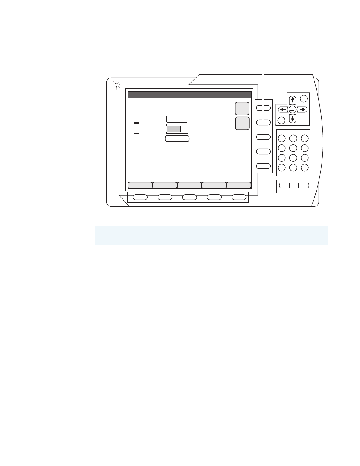
2. From the Welcome screen of the Instant Pilot, press the Details button (Figure 2).
The System Info screen appears. The System Info screen contains information about the
firmware versions of the configured system modules.
Thermo Scientific Agilent 1200 Series Getting Connected Guide for LC Devices 1
Page 14
1
Esc
Sequence
Status
Logbook
More
10:00
Select a button to continue
Display
Control
Details
Welcome
Quat Pump
Autosampler
Col Comp
Method
Agilent Technologies
7
8
9
456
12
3
0.~
i
Start Stop
Details button
Checking the Agilent Firmware Versions
Checking the Firmware Versions from the Xcalibur Data System
Figure 2. Welcome screen on the Agilent Instant Pilot
3. Compare the firmware versions to those in Ta bl e 1 on page ix.
IMPORTANT When you are done, to prevent data system failure, disconnect the Instant
Pilot cable from the LC stack.
Checking the Firmware Versions from the Xcalibur Data System
Before you can check the firmware versions of the Agilent LC modules from the Xcalibur data
system, you must first establish communication between the modules and the Xcalibur data
system.
You can monitor the status of the Agilent modules from the Xcalibur Information view. To
open or close the Information view, choose View > Info View.
To check the firmware versions of the LC modules from the Xcalibur data system
1. Establish communication with the Agilent LC system as follows:
a. Connect the Agilent local area network (LAN) interface to the data system computer.
See “Connecting the Ethernet Cables” on page 34.
b. Configure the Agilent LAN interface to use a stored IP address. See Chapter 2,
c. Specify the instrument configuration options for the LC modules in the Xcalibur
“Setting Up the LAN Interface.”
Instrument Configuration window. See “Configuring the Agilent LC System’s
Modules” on page 20.
2 Agilent 1200 Series Getting Connected Guide for LC Devices Thermo Scientific
Page 15

1
Checking the Agilent Firmware Versions
Checking the Firmware Versions from the Xcalibur Data System
2. Choose Start > All Programs > Thermo Xcalibur > Xcalibur to open the Xcalibur
application.
3. From the Xcalibur Roadmap view, choose View > Info View to open the Information
view, and then click the Status tab.
4. On the Status page, click the module name to view its status (Figure 3).
Note To trigger data acquisition from a Thermo Scientific mass spectrometer, you
must install a contact closure board in one of the Agilent modules and connect the
board to the Start In pins on the mass spectrometer power panel. See “Installing the
External Contact Interface Board” on page 29 and “Connecting the Contact Closure
Cable” on page 35.
Figure 3. Status page of the Xcalibur Roadmap View (example)
Thermo Scientific Agilent 1200 Series Getting Connected Guide for LC Devices 3
Page 16

Page 17

2
Setting Up the LAN Interface
This chapter describes how to configure the local area network (LAN) interface for the
Agilent 1200 Series LC system. For stable communication with the Xcalibur data system, one
of the modules in the Agilent LC system must contain either an on-board LAN interface or an
Agilent G1369 LAN card.
Note For more information, refer to the user manual for the Agilent LAN card.
Contents
• Determining the LAN Interface Type and Location
• Setting the LAN Initialization Mode to “Using Default”
• Setting the Stored TCP/IP Address for the LAN Interface
• Setting the LAN Initialization Mode to “Using Stored”
Determining the LAN Interface Type and Location
Agilent provides two options for the LAN interfaces:
• On-board LAN interface, which might be the standard configuration or you can order as
part of a module
• Agilent G1369 LAN card, which you can order separately
IMPORTANT Do not install more than one LAN card in the Agilent LC system. If one of
the modules in the LC stack includes an on-board LAN interface, do not install a LAN
card.
Thermo Scientific Agilent 1200 Series Getting Connected Guide for LC Devices 5
Page 18

2
LANUSB
REMOTE
RS-232
CANCAN
CONFIG
REMOTE FLASH
PCMCIA
ANALOG
1
ANALOG
2
Configuration switches
for an on-board LAN interface
On-board LAN interface port
Agilent G1369 LAN card
Setting Up the LAN Interface
Determining the LAN Interface Type and Location
To determine which module contains the LAN interface
Check the back panels of the modules for either an on-board LAN interface (Figure 4) or
a LAN card (Figure 5).
Note If the LC stack does not have a built-in LAN interface, Agilent recommends
that you install the Agilent G1369 LAN card in the detector, if part of the system. If
an Agilent detector is not part of the system, install the LAN card in the pump or
autosampler module. For instructions, refer to the manuals that came with the
Agilent 1200 Series LC system.
Figure 4. Location of the on-board LAN interface port (example)
Figure 5. Location of the LAN card (pump module, example)
ANALOG
Activity
Agilent Technologies
REMOTE RS-232
Speed
G1369 LAN Interface
CANCAN
CONFIG
6 Agilent 1200 Series Getting Connected Guide for LC Devices Thermo Scientific
Page 19

Setting the LAN Initialization Mode to “Using Default”
CONFIG
On
position
Off
position
Switches 7 and 8 are
in the On (up) position.
Setting the LAN Initialization Mode to “Using Default”
Before you configure the LAN interface parameters, set the LAN initialization mode to use
the default IP address. The initialization mode is set with three of the eight configuration
switches located on the LAN board.
• On-board LAN interface—Use switches 6, 7, and 8 located on the back of the module
that has the LAN connector.
• Agilent G1369 LAN card—Use switches 4, 5, and 6 located on the LAN card.
Follow one of these procedures:
• To set the on-board LAN interface’s initialization mode to use the default IP address
• To set the LAN card’s initialization mode to use the default IP address
To set the on-board LAN interface’s initialization mode to use the default IP address
Set the initialization switches on the back panel (Figure 6) as follows:
2
Setting Up the LAN Interface
Switch #
Position
678
Off On On
Figure 6. Back panel on-board LAN configuration switches set to the default IP address
To set the LAN card’s initialization mode to use the default IP address
1. For the module that contains the LAN card, turn off the power switch and unplug its
power supply cord.
CAUTION To prevent personal injury caused by an electric shock, always turn off the
module and unplug the power supply cord from the electrical outlet before removing
the cover.
Thermo Scientific Agilent 1200 Series Getting Connected Guide for LC Devices 7
2. If an Ethernet cable connects to the Ethernet port (LAN), disconnect the cable.
3. Ensure that you wear electrostatic discharge (ESD) protection.
Refer to the LC modules’ manuals for additional safety information and for information
about preventing ESD damage caused by an electrical discharge.
Page 20

2
12345678
Setting Up the LAN Interface
Setting the LAN Initialization Mode to “Using Default”
CAUTION To prevent damage to an instrument, always use ESD protection when
handling electronic boards and components.
4. Remove the LAN card from the module.
For instructions, refer to the manual for the Agilent G1369 LAN card. This LAN card
has a configuration switch that you can configure for the initialization modes. The card
ships with all eight switches set to the Off (down) position, which is the “Bootp”
initialization mode.
5. Set the initialization switches on the LAN card (Figure 7) as follows:
Switch #
Position
456
Off On On
The On position for the toggle switch is up and the Off position is down. With these
switch settings, the LAN card uses the factory default settings to enable a Transmission
Control/Internet Protocol (TCP/IP) connection to the LAN interface with a Telnet
session.
Figure 7. Configuration switches on the Agilent G1369 LAN card
8 Agilent 1200 Series Getting Connected Guide for LC Devices Thermo Scientific
Note The Agilent default settings are IP address 192.168.254.11 and subnet mask
255.255.0.0.
6. Reinstall the LAN card.
7. Using the Category 5 Ethernet cable, connect the LAN card directly to the dedicated
Ethernet port in the data system computer.
8. Plug in the disconnected power supply cord, and then turn on the LC modules.
Page 21

2
Setting the Stored TCP/IP Address for the LAN Interface
Setting the Stored TCP/IP Address for the LAN Interface
For an LC/MS system that includes an Agilent LC stack and a Thermo Scientific mass
spectrometer, set the IP address for the Agilent LAN interface to 172.16.0.102.
IMPORTANT If your LC/MS setup includes only one network card, use the mass
spectrometer’s IP address.
To set the stored TCP/IP address for the LAN interface
1. Follow the procedure “Setting the LAN Initialization Mode to “Using Default”” on
page 7.
2. Ensure that the LAN interface connects to the data system computer network card
labeled Surveyor MS.
3. Open the Internet Protocol Properties dialog box as follows:
Note During this procedure, the mass spectrometer temporarily loses communication
with the Xcalibur data system.
Setting Up the LAN Interface
a. Depending on the operating system, open the Local Area Connection Status dialog
box as follows (Figure 8):
• (Microsoft™ Windows™ 7 or later) Choose Start > Control Panel > Network
and Internet (or Networking and Sharing Center if set to the Icon view), and
then click Local Area Connection number.
–or–
• (Windows XP) Choose Start > Settings > Control Panel > Network
Connections > Local Area Connection.
Thermo Scientific Agilent 1200 Series Getting Connected Guide for LC Devices 9
Page 22

2
Windows XP Windows 7
Setting Up the LAN Interface
Setting the Stored TCP/IP Address for the LAN Interface
Figure 8. Local Area Connection Status dialog box (Windows 7 and XP)
b. Click Properties to open the Local Area Connection Properties dialog box.
10 Agilent 1200 Series Getting Connected Guide for LC Devices Thermo Scientific
Page 23

c. Do one of the following (Figure 9):
Windows XP Windows 7
• (Windows 7 or later) On the Networking page, select the Internet Protocol
Vers io n 4 ( TCP /IP v4 ) check box.
–or–
• (Windows XP) On the General page, select the Internet Protocol (TCP/IP)
check box.
Figure 9. Local Area Connection Properties dialog box
2
Setting Up the LAN Interface
Setting the Stored TCP/IP Address for the LAN Interface
Thermo Scientific Agilent 1200 Series Getting Connected Guide for LC Devices 11
Page 24

2
Setting Up the LAN Interface
Setting the Stored TCP/IP Address for the LAN Interface
d. Click Properties to open the Internet Protocol Version 4 (TCP/IPv4) Properties
dialog box (Figure 10).
“Version 4” and “IPv4” appear only in the dialog box for Windows 7 or later.
Figure 10. Internet Protocol Version 4 (TCP/IPv4) Properties dialog box with the IP
address for the dedicated Ethernet card
4. Set the IP address as follows:
a. Select the Use the Following IP Address option.
b. In the IP Address box, type 192.168.254.100.
c. In the Subnet Mask box, type 255.255.0.0.
d. Click OK.
5. (Windows 7 or later) Enable Telnet as follows:
a. Choose Start > Control Panel > Programs and Features (Icon view), and then click
Turn Windows Features On or Off to open the Windows Features dialog box.
b. Select the Te ln et C l i e n t check box, and then click OK.
12 Agilent 1200 Series Getting Connected Guide for LC Devices Thermo Scientific
Page 25

2
Command prompt
Setting Up the LAN Interface
Setting the Stored TCP/IP Address for the LAN Interface
6. Start a Telnet session with the Agilent LAN interface as follows:
a. Open the MS-DOS Command window as appropriate for your operating system:
• (Windows 7 or later) Choose Start, type cmd in the search box, and then press
ENTER.
–or–
• (Windows XP) Choose Start > Run, type cmd, and then click OK.
b. At the MS-DOS prompt, type cd c:\, and then press ENTER.
c. Type telnet 192.168.254.11, and then press ENTER (Figure 11).
Figure 11. Command Prompt window with the default IP address
The Telnet session with the Agilent LAN interface begins (Figure 12).
Figure 12. Beginning of a Telnet session with the Agilent LAN interface
7. Set the IP address for the Agilent LAN interface as follows:
a. At the command prompt (Figure 12), type a slash (/), and then press ENTER to
display the LAN interface’s current settings.
Ta bl e 2 lists the Telnet commands. Figure 13 shows a Telnet session with the LAN
Status Page displayed.
Table 2. Telnet commands (Sheet 1 of 2)
Value Description
/ Displays current settings.
ip <x.x.x.x> Sets a new IP address.
sm <x.x.x.x> Sets a new subnet mask address.
gw <x.x.x.x> Sets a new gateway address.
Thermo Scientific Agilent 1200 Series Getting Connected Guide for LC Devices 13
Page 26

2
IP address and
subnet mask for
an Agilent LC/
Thermo Scientific
MS system
Agilent default
IP address
Setting Up the LAN Interface
Setting the Stored TCP/IP Address for the LAN Interface
Table 2. Telnet commands (Sheet 2 of 2)
Value Description
quit Saves changes and exits the shell (for the G1369 LAN card).
exit (Model G1369 LAN card) Exits the Windows command line
Figure 13. Telnet session with the LAN Status Page
without saving the changes.
(On-board LAN interface) Saves the changes and exits the
Windows command line.
b. If the stored IP address is not set to 172.16.0.102, type ip 172.16.0.102, and then
press ENTER.
c. If the stored subnet mask is not set to 255.255.0.0, type sm 255.255.0.0, and then
press ENTER.
d. To verify the IP address and subnet mask settings, type a slash (/), and then press
ENTER to display the current settings of the LAN interface.
8. To exit the Telnet session, do one of the following:
• For the on-board LAN interface, type exit at the prompt.
–or–
• For the LAN card, type quit at the prompt.
14 Agilent 1200 Series Getting Connected Guide for LC Devices Thermo Scientific
Page 27

2
Setting Up the LAN Interface
Setting the Stored TCP/IP Address for the LAN Interface
9. After exiting the Telnet session, restore the TCP/IP address for the data system computer
network card (labeled Surveyor MS) to the original settings as follows (Figure 14):
a. Open the Internet Protocol Version 4 (TCP/IPv4) Properties dialog box (see step 3
on page 9).
Figure 14. Internet Protocol Version 4 (TCP/IPv4) Properties dialog box
b. In the IP Address box, type 172.16.0.101.
c. In the Subnet Mask box, type 255.255.0.0.
d. Click OK.
e. Exit the Control Panel.
After setting the stored IP address and subnet mask for the Agilent LAN interface, you are
ready to change the LAN interface initialization switches so that the LAN interface uses the
stored IP address. See Setting the LAN Initialization Mode to “Using Stored”.
Thermo Scientific Agilent 1200 Series Getting Connected Guide for LC Devices 15
Page 28

2
Setting Up the LAN Interface
Setting the LAN Initialization Mode to “Using Stored”
Setting the LAN Initialization Mode to “Using Stored”
After you configure the IP address by using the Telnet session, set the initialization mode to
use the stored IP address setting. The initialization mode is set with three of the eight
configuration switches located on the LAN board.
• On-board LAN interface—Use switches 6, 7, and 8 located on the back of the module
that has the LAN connector.
• Agilent G1369 LAN card—Use switches 4, 5, and 6 located on the LAN card.
Follow one of these procedures:
• To set the on-board LAN interface’s initialization mode to use the stored IP address
• To set the LAN card’s initialization mode to use the stored IP address
To set the on-board LAN interface’s initialization mode to use the stored IP address
Set the initialization switches on the back panel (Figure 6 on page 7) as follows:
Switch #
Position
678
Off On Off
The On position for the toggle switch is up and the Off position is down.
To set the LAN card’s initialization mode to use the stored IP address
1. For the module that contains the LAN card, turn off the power switch and unplug its
power supply cord.
CAUTION To prevent personal injury caused by an electric shock, always turn off the
module and unplug the power supply cord from the electrical outlet before removing
the cover.
2. If an Ethernet cable connects to the Ethernet (LAN) port, disconnect the cable.
3. Ensure that you wear ESD protection.
CAUTION To prevent damage to an instrument, always use ESD protection when
handling electronic boards and components.
4. Remove the LAN card from the module.
16 Agilent 1200 Series Getting Connected Guide for LC Devices Thermo Scientific
Page 29

2
Setting Up the LAN Interface
Setting the LAN Initialization Mode to “Using Stored”
5. Set the initialization switches on the LAN card (Figure 7 on page 8) as follows:
Switch #
Position
456
Off On Off
The On position for the toggle switch is up and the Off position is down.
6. Reinstall the LAN card.
7. Using the Category 5 Ethernet cable, connect the LAN card directly to the dedicated
Ethernet port in the data system computer.
8. Plug in the disconnected power supply cord, and then turn on the LC modules.
Thermo Scientific Agilent 1200 Series Getting Connected Guide for LC Devices 17
Page 30

Page 31

3
Setting Up the Thermo Foundation Instrument Configuration
This chapter describes how to add the Agilent 1200 Series modules to the Thermo
Foundation Instrument Configuration window and specify their configuration options.
Contents
• Agilent 1200 Series LC System IP Address
• Contact Interface Board
• Configuring the Agilent LC System’s Modules
Agilent 1200 Series LC System IP Address
You enter the stack IP address (172.16.0.102) for the Agilent LC system when you configure
the modules. After you enter the stack IP address for one module, this IP address appears in
the configuration dialog box for each connected device.
IMPORTANT To maintain stable communication with the Thermo Scientific data system,
you must set the Agilent LAN interface to use a stored IP address. For information about
configuring the Agilent LAN interface to use a stored IP address, see Chapter 2, “Setting
Up the LAN Interface.”
Thermo Scientific Agilent 1200 Series Getting Connected Guide for LC Devices 19
Page 32

3
Setting Up the Thermo Foundation Instrument Configuration
Contact Interface Board
Contact Interface Board
The LC Devices DVD contains device drivers for the following Agilent 1200 Series modules:
• Agilent HiP-ALS (autosampler)
• Agilent Micro Well Plate (autosampler)
• Agilent Thermostatted Column Compartment (TCC)
•Agilent Binary Pump
• Agilent Capillary Pump
•Agilent Quaternary Pump
• Agilent Diode Array Detector (DAD)
To trigger data acquisition during a sequence run
1. Install the external contact interface (closure) board in one of the modules (typically the
autosampler).
For instructions, see Chapter 4, “Installing the External Contact Interface Board.”
2. When you specify the configuration options for the LC system, select the Contact Board
Installed check box for the module that contains this board.
Configuring the Agilent LC System’s Modules
To specify the configuration options for the LC modules, follow these procedures:
• Adding the Agilent 1200 Series Modules to the Foundation Instrument Configuration
• Setting the Configuration Options for the LC Modules
• Closing Foundation Instrument Configuration
Adding the Agilent 1200 Series Modules to the Foundation Instrument Configuration
To add the LC modules to the Foundation instrument configuration
IMPORTANT The Thermo Scientific data system does not support the simultaneous
control of Agilent LC modules from different LC series.
1. Turn on the modules in the Agilent LC stack.
2. Choose Start > All Programs > Thermo Foundation x.x > Instrument Configuration
to open the Thermo Foundation Instrument Configuration window (Figure 15).
20 Agilent 1200 Series Getting Connected Guide for LC Devices Thermo Scientific
Page 33

3
Setting Up the Thermo Foundation Instrument Configuration
Configuring the Agilent LC System’s Modules
Figure 15. Thermo Foundation Instrument Configuration window
3. Under Available Devices, double-click the icon for each module that you want to add to
the Configured Devices area.
4. Configure the selected modules. See the next section.
Setting the Configuration Options for the LC Modules
To set the configuration options for the Agilent LC modules that the Foundation platform
supports, follow these procedures:
• Configuring the Agilent 1200 Series Autosampler
• Configuring the Agilent 1200 Series Pump
• Configuring the Agilent 1200 Series Thermostatted Column Compartment
• Configuring the Agilent 1200 Series Detector
Thermo Scientific Agilent 1200 Series Getting Connected Guide for LC Devices 21
Page 34

3
Setting Up the Thermo Foundation Instrument Configuration
Configuring the Agilent LC System’s Modules
Configuring the Agilent 1200 Series Autosampler
Use the autosampler’s configuration dialog box to specify its module name; the stack IP
address; configurable instrument options such as the size of the syringe, seat capillary, and
loop capillary; the tray type you are using; and whether the system has an optional thermostat
unit.
To specify the configuration options for the autosampler
1. Follow the procedure “To add the LC modules to the Foundation instrument
configuration” on page 20.
2. In the Instrument Configuration window, under Configured Devices, double-click the
autosampler icon, and then do the following on the General page (Figure 16):
Figure 16. General page of the Agilent 1200 G1367 HiP-ALS dialog box (example)
• If you installed the contact interface board in the autosampler, select the Contact
Board Installed check box.
Note When you select the Contact Board Installed check box, the Timed Events
page appears in the Instrument Setup view for the autosampler. See Chapter 6,
“Triggering Data Acquisition.”
• In the Stack IP Address box, make sure that the IP address is 172.16.0.102.
All of the Agilent LC modules in the stack share the TCP/IP settings. Changing the
value of a setting for one module in the Instrument Configuration window changes
the value of that setting for all modules in the stack.
• If there is more than one model number in the Module Name list, select the model
number located on the front, lower-right corner of the module.
22 Agilent 1200 Series Getting Connected Guide for LC Devices Thermo Scientific
Page 35

3
Setting Up the Thermo Foundation Instrument Configuration
Configuring the Agilent LC System’s Modules
3. Click the Tray & Thermostat tab (Figure 17), and then do the following:
Figure 17. Tray & Thermostat page of the Agilent 1200 G1367 HiP-ALS dialog box (example)
• Under Metering Device, select options from the Syringe, the Seat Capillary, and the
Loop Capillary lists.
• Under Tray Combination, select the tray type.
For information about the vial and tray locations, see Chapter 7, “Vial and Well
Locations for the Available Tray Types.”
• If the Agilent stack has an autosampler thermostat module (G1330B), select the
Thermostat Control Installed check box.
4. Click OK.
Configuring the Agilent 1200 Series Pump
Use the pump’s configuration dialog box to specify its serial number and model number. For
the binary pump, you can also specify whether the system has the optional selection valve
installed.
IMPORTANT Be sure to enter the correct serial number when you configure the pump.
Otherwise, the Thermo Scientific data system cannot communicate with the pump.
Thermo Scientific Agilent 1200 Series Getting Connected Guide for LC Devices 23
Page 36

3
Setting Up the Thermo Foundation Instrument Configuration
Configuring the Agilent LC System’s Modules
To specify the configuration options for the pump
1. Follow the procedure “To add the LC modules to the Foundation instrument
configuration” on page 20.
2. In the Instrument Configuration window, under Configured Devices, double-click the
pump icon, and then do the following on the General page (Figure 18):
Figure 18. General pages of the Agilent 1200 G1312 Bin Pump and Agilent 1200 Capillary Pump dialog boxes
• If you installed the contact interface board in the pump, select the Contact Board
Installed check box.
Note When you select the Contact Board Installed check box, the Timed Events
page appears in the Instrument Setup view for the pump. See Chapter 6,
“Triggering Data Acquisition.”
• In the Stack IP Address box, make sure that the IP address is 172.16.0.102.
All Agilent 1200 LC modules in the stack share the TCP/IP settings. Changing the
value of a setting for one module in the Instrument Configuration window changes
the value of that setting for all modules in the stack.
• In the Serial Number box, type the serial number that is located on the front,
lower-right corner of the Agilent module.
Because you can configure two pumps per stack, you must type the correct serial
number to initiate communication between the pump and the Thermo Scientific
data system.
• If there is more than one model number in the Module Name list, select the model
number located on the front, lower-right corner of the module.
3. For the binary pump, if the LC stack has an optional selection valve, click the
Selection Valve tab, and then select the Solvent Selection Valve Installed check box.
24 Agilent 1200 Series Getting Connected Guide for LC Devices Thermo Scientific
Page 37

3
Setting Up the Thermo Foundation Instrument Configuration
Configuring the Agilent LC System’s Modules
4. For the capillary pump, click the Options tab, and then select the Normal Mode or
Micro Mode option. If you select the Micro Mode option, select the flow sensor rate
(Figure 19).
Figure 19. Options page of the Agilent 1200 Capillary Pump dialog box
5. Click OK.
Configuring the Agilent 1200 Series Thermostatted Column Compartment
Use the thermostatted column compartment (TCC) configuration dialog box to specify its
model number.
To specify the configuration options for the TCC
1. Follow the procedure “To add the LC modules to the Foundation instrument
configuration” on page 20.
2. In the Instrument Configuration window, under Configured Devices, double-click the
TCC icon, and then do the following on the General page (Figure 20):
Figure 20. General page of the Agilent 1200 G1316 TCC dialog box
Thermo Scientific Agilent 1200 Series Getting Connected Guide for LC Devices 25
Page 38

3
Setting Up the Thermo Foundation Instrument Configuration
Configuring the Agilent LC System’s Modules
• In the Stack IP Address box, make sure that the IP address is 172.16.0.102.
Note All Agilent LC modules in the stack share the TCP/IP settings. Changing
the value of a setting for one module in the Instrument Configuration window
changes the value of that setting for all modules in the stack.
• In the Module Name list, select the model number located on the front, lower-right
corner of the module.
3. Click OK.
Configuring the Agilent 1200 Series Detector
Use the DAD instrument configuration window to specify the detector model number. When
applicable, you can also specify the detector as having the contact interface board installed.
To specify the configuration options for the detector
1. Follow the procedure “To add the LC modules to the Foundation instrument
configuration” on page 20.
2. In the Instrument Configuration window, under Configured Devices, double-click the
detector icon, and then do the following on the General page (Figure 21):
• If you installed the contact interface board in the detector, select the Contact Board
Installed check box.
Note
• When you select the Contact Board Installed check box, the Timed Events
page appears in the Instrument Setup view for the detector. See Chapter 6,
“Triggering Data Acquisition.”
• You cannot install the external contact interface board in Model G1315C or
G1315D of the Agilent 1200 Series DAD.
• In the Stack IP Address box, make sure that the IP address is 172.16.0.102.
\
Note All modules in the Agilent LC stack share the TCP/IP settings. Changing
the value of a setting for one module in the Instrument Configuration window
changes the value of that setting for all modules in the stack.
26 Agilent 1200 Series Getting Connected Guide for LC Devices Thermo Scientific
Page 39

3
Setting Up the Thermo Foundation Instrument Configuration
Configuring the Agilent LC System’s Modules
• In the Module Name list, select the model number located on the front, lower-right
corner of the module.
Figure 21. General page of the Agilent 1200 G1315 DAD dialog box (example)
3. Click OK.
Closing Foundation Instrument Configuration
Before opening the Thermo Scientific data system, close the Foundation Instrument
Configuration window. You cannot have both applications open at the same time.
To close the Foundation Instrument Configuration window
After you configure all of the Agilent LC modules, click Done.
Thermo Scientific Agilent 1200 Series Getting Connected Guide for LC Devices 27
Page 40

Page 41

4
Installing the External Contact Interface Board
1 8
CAN CAN HP-1B CONFIG
RELAY CONTACTS
REMOTE
VIAL- # -OUTPUT
RS232
Screws that secure
the cover plate
To send a trigger signal from the Agilent LC system to a Thermo Scientific mass spectrometer,
the Agilent 1200 Series autosampler or pump must have an external contact binary-coded
decimal (BCD) interface board (Figure 22).
For information about ordering the BCD board, refer to the manuals supplied with the
Agilent LC modules.
Figure 22. External contact interface board (BCD board) installed in an Agilent pump
Thermo Scientific Agilent 1200 Series Getting Connected Guide for LC Devices 29
Page 42

4
On
position
Off
position
Installing the External Contact Interface Board
To install the external contact interface board
1. For the selected module (autosampler or pump), turn off the power switch and unplug
the power supply cord (Figure 23).
CAUTION To prevent personal injury caused by an electric shock, always turn off the
Agilent module and unplug its power supply cord from the electrical outlet before
removing the cover.
Figure 23. Power switches on the front of the Agilent 1200 Series modules
2. Ensure that you wear ESD protection.
Refer to the LC modules’ manuals for additional safety information and for information
about preventing ESD damage caused by an electrical discharge.
CAUTION To prevent damage to an instrument, always use ESD protection when
handling electronic boards and components.
3. Using a slotted screwdriver, remove the back cover plate over the empty board slot.
4. Insert the contact interface board into the slot, and then tighten the two screws to secure
the board to the enclosure (Figure 22 on page 29).
This completes the installation of the contact interface board.
30 Agilent 1200 Series Getting Connected Guide for LC Devices Thermo Scientific
Page 43

4
Installing the External Contact Interface Board
5. Trigger data acquisition from the Thermo Scientific mass spectrometer as follows:
a. Connect the external contact trigger cable.
b. When you configure the module with the contact interface board (see “Configuring
the Agilent LC System’s Modules” on page 20), make sure that you select the Contact
Board Installed check box.
c. When you create an instrument method for the LC/MS system, make sure that you
create an appropriate time program for the trigger signal. See Chapter 6, “Triggering
Data Acquisition.”
Thermo Scientific Agilent 1200 Series Getting Connected Guide for LC Devices 31
Page 44

Page 45

5
Connecting the Communication Cables
This chapter describes how to connect the Agilent 1200 Series LC modules to the data system
computer and how to make the contact closure connection between the LC stack and a
Thermo Scientific mass spectrometer.
Contents
• Ethernet Communication Kit
• Connecting the Ethernet Cables
• Connecting the Contact Closure Cable
Ethernet Communication Kit
To connect the Agilent LC system to a Thermo Scientific mass spectrometer, you must have
the following parts:
• Ethernet Communication Kit (Ta bl e 3 )
• Agilent LAN card, Model G1369, unless the Agilent LC system contains a module with
an on-board LAN communication interface (Figure 24)
• Agilent BCD board for contact closure
Table 3. Ethernet Communication Kit (P/N OPTON 30012)
Description Part number
Agilent BCD (contact interface) board 00012-27714
a
Contact closure cable with 15-pin connector
Ethernet cable, straight shielded Cat5, 3 m (10 ft) 00012-70008
Fast Ethernet switch, 10T/100Base-TX, 5-port 00825-01-00024
a
Instead of using the contact closure (trigger) cable, you can use the contact closure cable supplied by Agilent
Technologies Inc. (P/N G1103-61611)
Thermo Scientific Agilent 1200 Series Getting Connected Guide for LC Devices 33
00012-27716
Page 46

5
REMOTE RS-232
CONFIG
ANALOG
CAN CAN
Agilent Technologies
Activity
Speed
G1369 LAN Interface
LANUSB
REMOTE
RS-232
CANCAN
CONFIG
REMOTE FLASH
PCMCIA
ANALOG
1
ANALOG
2
CONFIG
Agilent LAN interface card
(Model G1369)
On-board LAN interface
port on the detector
Connects to the
Ethernet switch.
Initialization switches
Connects to the
Ethernet switch.
Connecting the Communication Cables
Connecting the Ethernet Cables
Connecting the Ethernet Cables
CAUTION Safety and EMC regulations require the use of Category 5 shielded Ethernet
communication cables, maximum 3 m (10 ft) long.
To connect the Ethernet communication cable to an Agilent LC stack
1. Connect one Ethernet cable from the LAN interface port (Figure 24) to the Ethernet
switch.
Figure 24. Ethernet connection to the two types of LAN interfaces
2. Connect the second Ethernet cable from the Ethernet switch to the Ethernet network
card in the data system computer that is dedicated to the LC/MS system (typically
network interface card number 3).
34 Agilent 1200 Series Getting Connected Guide for LC Devices Thermo Scientific
Page 47

Connecting the Contact Closure Cable
2-pin connector supplied
with the mass spectrometer
DB15 connector DB15 connector
An external contact closure (trigger) cable relays the start signal from the Agilent LC module
to the Thermo Scientific mass spectrometer. One end of the cable has a DB15 connector and
the other end has a set of exposed wires.
Figure 25 shows the contact closure cable set up for a Thermo Scientific TSQ™ Series mass
spectrometer with a 2-pin connector. For ordering information, see “Ethernet
Communication Kit” on page 33.
Figure 25. Contact closure cable set up with a 2-pin connector
5
Connecting the Communication Cables
Connecting the Contact Closure Cable
Note The instrument control platform for the Thermo Scientific mass spectrometer must
be compatible with the LC Devices instrument control application, and the instrument
control applications must be compatible with the Thermo Scientific application installed
on your data system computer. See the LC Devices Release Notes.
To connect the contact closure cable to the mass spectrometer
1. Follow the procedure “To install the external contact interface board” on page 30.
2. Using an appropriate connector for the mass spectrometer, connect the white wire from
the contact closure cable to the Start In+ pin and the brown wire to the Start In– pin on
the mass spectrometer’s input/output (I/O) panel (Figure 26).
3. Connect the cable’s DB15 plug to the RELAY CONTACTS socket located on the LC
module’s installed contact interface board (Figure 26).
Thermo Scientific Agilent 1200 Series Getting Connected Guide for LC Devices 35
Page 48

5
(right-side
panel)
(left-side
panel)
White wire
Brown wire
TSQ Series MS
(back panel)
LCQ Fleet™,
LTQ™ Series, or
LXQ™ MS
(right-side panel)
Surveyor™
MSQ™ MS
(back panel)
LCQ™ Series MS
(back panel)
(Not drawn to scale)
Contact closure cable
connects to the relay contacts
on the contact interface board.
Connecting the Communication Cables
Connecting the Contact Closure Cable
Figure 26. Example contact closure connections between the Agilent contact interface board and the Thermo Scientific MS
START IN
-
+
START IN
START IN
+
–
(5V Max)
(5V Max)
36 Agilent 1200 Series Getting Connected Guide for LC Devices Thermo Scientific
Start In +
Start In
-
Page 49

6
Triggering Data Acquisition
This chapter describes how to set up the LC/MS system so that the Agilent 1200 module with
the external contact interface board triggers the Thermo Scientific mass spectrometer (MS) to
start data acquisition.
CAUTION To prevent a data system failure, make sure that you disconnect the Agilent
Instant Pilot cable from the LC stack before you run data acquisitions or use the direct
control commands.
Note Instrument methods contain the contact closure signals (to trigger data acquisition),
the chromatographic conditions, and the mass spectrometer settings for an LC/MS
application.
If you have not already installed the contact interface board, start with these procedures:
• “Installing the External Contact Interface Board” on page 29
• “Connecting the Contact Closure Cable” on page 35
To trigger data acquisition during a run
1. Choose Start > All Programs > Thermo Xcalibur > Xcalibur, and then click the
Instrument Setup icon.
Note The Instrument Setup window might take several seconds to open. If you
receive a server failure error, follow the instructions on page viii.
2. Click the icon for the LC module that contains the contact interface board (typically the
autosampler) to open its Instrument Setup window.
3. Click the Timed Events tab.
Note If the Timed Events tab is not shown, close the Xcalibur data system and follow
the instructions in “Setting the Configuration Options for the LC Modules” on
page 21.
Thermo Scientific Agilent 1200 Series Getting Connected Guide for LC Devices 37
Page 50

6
Triggering Data Acquisition
4. In the Timed Events table, do the following:
a. In row 1, select the Contact A cell, and then select Closed from the list (Figure 27).
b. In row 2, do the following:
i. Select the Time (min) cell, and then type 0.10.
ii. Select the Contact A cell, and then select Open from the list.
c. Make sure that all the other Contact cells display Open.
Figure 27. Table on the Timed Events page
5. Make the appropriate entries and selections for the rest of the instrument method.
6. Save the instrument method with an appropriate name.
38 Agilent 1200 Series Getting Connected Guide for LC Devices Thermo Scientific
Page 51

7
Vial and Well Locations for the Available Tray Types
This chapter describes the vial and well locations for the tray types available from the Xcalibur
data system.
Note Left/Back is the factory default setting for the orientation of plates (plate rotation
setting). For the Left/Back plate rotation, the A1 well location is to the left and at the back
of the plate.
You can change the plate rotation to Right/Front by using the Agilent Instant Pilot
controller. For instructions, refer to the reference manual for the Agilent LC stack.
Contents
• 40-Vial Trays
• 100-Vial Tray
• 54-Vial Plates
• 96-Well Plates or 96-Deep Well Plates
• 384-Well Plates
Thermo Scientific Agilent 1200 Series Getting Connected Guide for LC Devices 39
Page 52

7
41 71
Row 1
Row 10
Left tray
1
31
Right tray
Column 1 to column 4
Column 1 to column 4
Vial and Well Locations for the Available Tray Types
40-Vial Trays
40-Vial Trays
You can load two 40-vial trays into the autosampler’s tray compartment. The Xcalibur data
system recognizes these trays as the left and right trays.
Figure 28 shows the vial locations for the 40-vial trays. When you create a sequence, you can
type a vial location from 1 to 40 for a single tray or 1 to 80 for two trays.
If you turn on the wash option for an instrument method, you can specify a wash vial from
1 to 40 or 1 to 80, depending on whether you load one or two trays into the tray
compartment.
Figure 28. Two 40-vial trays
40 Agilent 1200 Series Getting Connected Guide for LC Devices Thermo Scientific
Page 53

100-Vial Tray
7
Vial and Well Locations for the Available Tray Types
100-Vial Tray
You can load one 100-vial tray into the autosampler’s tray compartment. The Xcalibur data
system recognizes this tray as the left tray.
Figure 29 shows the vial locations for the 100-vial tray. When you create a sequence, you can
type a vial location from 1 to 100.
If you turn on the wash option for an instrument method, you can specify a wash vial from
1 to 100.
Figure 29. 100-vial tray
Row 10
Row 1
191
Column 1 Column 10
Thermo Scientific Agilent 1200 Series Getting Connected Guide for LC Devices 41
Page 54

7
Vial and Well Locations for the Available Tray Types
54-Vial Plates
54-Vial Plates
You can load two 54-vial plates into the autosampler’s tray compartment. The Xcalibur data
system recognizes these plates as the front and back vial plates.
Figure 30 shows the vial locations for the “54-vial plate + 10 × 2 mL” tray option (three
plates) with the factory default setting of Left/Back for the plate rotation. When you create a
sequence, you can type a vial location from 1:A1 to 1:F9 for the front plate, from 2:A1 to
2:F9 for the back plate, and from 3:A1 to 3:J1 for the vials.
If you turn on the wash option for an instrument method, you can specify a “well” location
from 1:A1 to 2:F9 or a reservoir location from 1 to 10.
Figure 30. Two 54-vial plates and one vial column with Left/Back for the plate rotation selection
A
Row 1
2:A1
Row 10
J
I
Plate 2
Plate 1
Row 6
Row 1
Row 6
H
G
Column 1
9
F
E
D
C
B
A
Plate 3 (10 × 2 mL vials)
Injection port
(sequence location = 3:A1)
Row 1
(wash vial location = 1)
F
A
1:A1
F
1
Columns
42 Agilent 1200 Series Getting Connected Guide for LC Devices Thermo Scientific
Page 55

96-Well Plates or 96-Deep Well Plates
You can load two 96-well plates or 96-deep well plates into the autosampler’s tray
compartment. The Xcalibur data system recognizes these plates as the front and back well
plates.
Figure 31 shows the well locations with the factory default setting of Left/Back for the plate
rotation. When you create a sequence, you can type a well location from 1:A1 to 1:H12 for
the front well plate, from 2:A1 to 2:H12 for the back well plate, and from 3:A1 to 3:J1 for the
vials.
If you turn on the wash option for an instrument method, you can specify a well location
from 1:A1 to 2:H12 or a reservoir location from 1 to 10.
Figure 31. Two 96-well plates and one vial column with Left/Back for the plate rotation selection
Row 1
A
2:A1
7
Vial and Well Locations for the Available Tray Types
96-Well Plates or 96-Deep Well Plates
J
Row 10
I
Plate 2
Plate 1
Row 8
Row 1
Row 8
A
H
H
H
G
F
1:A1
1 12
Columns
E
D
C
B
A
Column 1
Plate 3 (10 × 2 mL vials)
Injection port
(sequence location = 3:A1)
Row 1
(wash vial location = 1)
Thermo Scientific Agilent 1200 Series Getting Connected Guide for LC Devices 43
Page 56

7
Injection port
A
B
C
D
E
F
G
H
I
J
Plate 3 (10 × 2 mL vials)
124
Plate 1
Plate 2
Row 1
Row 10
Column
(sequence location = 3:A1)
(wash vial location = 1)
Row 16
Row 1
P
A
Row 16
Row 1PA
Vial and Well Locations for the Available Tray Types
384-Well Plates
384-Well Plates
You can load two 384-well plates into the autosampler’s tray compartment. The Xcalibur data
system recognizes these plates as the front and back well plates.
Figure 32 shows the well locations for the 384-well plates (factory default setting of
Left/Back) and the vial locations for the 2 mL vials. When you create a sequence, you can type
a well location from 1:A1 to 1:P24 for the front well plate, from 2:A1 to 2:P24 for the back
well plate, and from 3:A1 to 3:J1 for the vials.
If you turn on the wash option for an instrument method, you can specify a well location
from 1:A1 to 2:P24 or a reservoir location from 1 to 10.
Figure 32. Two 384-well plates and one vial column with Left/Back for the plate rotation selection
44 Agilent 1200 Series Getting Connected Guide for LC Devices Thermo Scientific
Page 57

I
Index
Numerics
100-vial trays 41
384-well plates 44
40-vial trays 40
54-vial plates 42
96-well or deep-well plates 43
A
Agilent 1200 Series
compatible firmware versions
configuring
autosampler
detector 26
pump 23
thermostatted column compartment 25
note, mixed series 20
Agilent G1369 LAN interface card, photo of 8
autosampler, configuring 22
22
ix
B
BCD board for contact closure
See contact interface board
C
cables
contact closure (trigger)
connecting
description 35
Ethernet, connecting 34
computer requirements vii
configuring the modules
See Agilent 1200 Series
contact interface board
autosampler
detector 26
device drivers 20
35
22
installing 30
pump 24
contacting us xi
cover, removing from a module 7, 30
D
data acquisition 37
data acquisitions, triggering 37
detector, configuring 26
device drivers vii
direct control commands, note for 37
documentation
accessing
additional vi
vi
E
EMC compliance 34
error message, server failure viii
ESD precaution 8, 30
Ethernet cable connections 34
Ethernet Communication Kit 33
F
firmware versions
supported
viewing from Xcalibur 2
viewing with the Instant Pilot 1
ix
I
Instant Pilot
caution note
Welcome screen 2
Instrument Configuration window, opening 20
instrument control platform, compatibility 35
instrument methods, triggering data acquisition 37
37
Thermo Scientific Agilent 1200 Series Getting Connected Guide for LC Devices 45
Page 58

Index: L
Instrument Setup window
opening
Timed Events page 22
Internet Protocol (TCP/IP) Properties dialog box 12
IP address
Agilent LAN interface
LC/MS network card 15
37
9
L
LAN communication, figure 34
LAN initialization modes
use default
G1369 LAN card setting
on-board LAN interface setting 7
use stored
G1369 LAN card setting
on-board LAN interface setting 16
LAN interface, location of 6
8
17
M
mass spectrometer
contact closure cable, connecting
I/O panel 35
mass spectrometry applications v
module name 24
35
Telnet
commands
session, starting 13
thermostatted column compartment (TCC), configuring 25
Timed Events page
device with the contact board
Instrument Setup window 22
tray types
factory default setting
plate rotation 39
trigger cable 35
13
38
39
W
Welcome screen (Instant Pilot) 2
P
pump, configuring 24
R
relay contacts
connecting the contact closure cable
location of 29
release notes vii
requirements
computer
software vii
vii
35
S
server failure error message viii
software requirements vii
stack IP address 22, 24, 26
subnet mask for the Surveyor MS network card 12, 15
system failure, preventing 37
system requirements vii
T
TCP/IP address 14
46 Agilent 1200 Series Getting Connected Guide for LC Devices Thermo Scientific
 Loading...