

Thermo Scientific Dionex UltiMate 3000 Series, FLD-3100, FLD-3400RS Operating Instructions Manual
Page 1
Thermo Scientific Dionex
UltiMate 3000 Series
Fluorescence Detectors
FLD-3100 and FLD-3400RS
Operating Instructions
(Original Operating Instructions)
Revision: 1.3
Date: September 2013
© 2013 Thermo Fisher Scientific Inc.
Doc. No. 4820.7850
Page 2

UltiMate 3000 Series:
Fluorescence Detectors FLD-3100 and FLD-3400RS
Operating Instructions
Page 3

UltiMate 3000 Series:
Fluorescence Detectors FLD-3100 and FLD-3400RS
Declaration of Conformity
(Original Declaration of Conformity)
Product: Thermo Scientific Dionex UltiMate 3000 - Detector
Types: FLD-3100 and FLD-3400RS
Dionex Softron GmbH herewith declares conformity of the above products with
the respective requirements of the following regulations:
• Low-Voltage Directive 2006/95/EC
• EMC Directive 2004/108/EC
The electrical safety of the products was evaluated based on the following
standard:
• DIN EN 61010-1:2010
Safety requirements for electrical equipment for measurement, control
and laboratory use, Part 1: General Requirements
The Electromagnetic Compatibility (EMC) of the products was evaluated based
on the following standard:
• DIN EN 61326:2006
Electrical equipment for measurement, control and laboratory use
EMC Requirements
This declaration is issued for the manufacturer
Dionex Softron GmbH
Part of Thermo Fisher Scientific Inc.
Dornierstraße 4
D-82110 Germering
by the Managing Director, Rüdiger Obst, and
the Vice President HPLC, Fraser McLeod.
September 2, 2013
Operating Instructions Page I
Page 4

UltiMate 3000 Series:
Fluorescence Detectors FLD-3100 and FLD-3400RS
Page II Operating Instructions
Page 5

UltiMate 3000 Series:
Fluorescence Detectors FLD-3100 and FLD-3400RS
Table of Contents
1 Introduction ................................................................................................................... 1
1.1 How to Use This Manual ........................................................................................... 1
1.2 Safety ......................................................................................................................... 3
1.2.1 Symbols on the Instrument and in the Manual ................................................. 3
1.2.2 Safety Precautions ............................................................................................ 5
1.2.3 Consignes de Sécurité ....................................................................................... 8
1.3 Intended Use ............................................................................................................ 12
1.4 Federal Communications Commission (FCC) Note ................................................ 14
2 Overview ...................................................................................................................... 15
2.1 Unit Description ....................................................................................................... 15
2.2 Operating Principle .................................................................................................. 16
2.3 Configurations ......................................................................................................... 19
2.4 Interior Components ................................................................................................ 20
2.5 Front Panel Elements ............................................................................................... 21
2.6 Rear Panel ................................................................................................................ 22
2.6.1 Power Switch .................................................................................................. 22
2.6.2 Fuse Cartridge ................................................................................................ 22
2.6.3 USB Port ......................................................................................................... 23
2.6.4 Analog Outputs (Optional) ............................................................................. 23
2.7 Fluid Connections .................................................................................................... 23
2.8 Flow Cells ................................................................................................................ 24
2.9 Lamp ........................................................................................................................ 25
2.10 Leak Sensor .......................................................................................................... 25
2.11 Detector Control .................................................................................................. 26
2.12 System Wellness, Predictive Performance, and Diagnostics ............................... 27
3 Installation ................................................................................................................... 29
3.1 Facility Requirements .............................................................................................. 29
3.2 Unpacking ................................................................................................................ 30
3.3 Positioning the Detector in the UltiMate 3000 System ........................................... 31
3.4 Connecting the Detector .......................................................................................... 32
3.4.1 General Information ....................................................................................... 32
3.4.2 Connecting the USB Cable ............................................................................. 32
3.4.3 Connecting the Power Cord ............................................................................ 34
3.4.4 Connecting the Analog Outputs (Optional) .................................................... 34
3.5 Setting Up the Detector in Chromeleon ................................................................... 37
3.5.1 Loading the USB Driver for the Detector ...................................................... 37
3.5.2 Installing the Detector .................................................................................... 39
3.5.3 Configuring the Detector ................................................................................ 40
3.6 Setting Up the Detector in DCMSLink .................................................................... 44
Operating Instructions Page i
Page 6

UltiMate 3000 Series:
Fluorescence Detectors FLD-3100 and FLD-3400RS
4 Preparation for Operation (Startup) ........................................................................ 45
4.1 Overview .................................................................................................................. 45
4.2 General Precautions for Connecting Capillaries ...................................................... 46
4.3 Connecting the Drain System .................................................................................. 47
4.4 Installing the Flow Cell ............................................................................................ 48
4.5 Equilibrating the System .......................................................................................... 51
4.6 General Guidelines for Detector Operation ............................................................. 52
4.6.1 Mobile Phases ................................................................................................. 52
4.6.2 Mobile Phase Delivery System ....................................................................... 53
4.6.3 Flow Cells ....................................................................................................... 53
5 Operation and Maintenance ...................................................................................... 55
5.1 Power-Up ................................................................................................................. 55
5.2 Detector Display ...................................................................................................... 55
5.3 Menus on the Detector Display ................................................................................ 57
5.3.1 Detector Menus ............................................................................................... 58
5.3.2 General Menu Layout and Structure ............................................................... 59
5.3.3 Main Menu ...................................................................................................... 61
5.3.4 Configuration Menu ........................................................................................ 62
5.3.5 Diagnostics Menu ........................................................................................... 63
5.3.6 Service Menu .................................................................................................. 63
5.4 Operation with Chromeleon ..................................................................................... 64
5.4.1 Connecting to Chromeleon ............................................................................. 64
5.4.2 Direct Control ................................................................................................. 65
5.4.3 Automated Control ......................................................................................... 67
5.4.4 SmartStartup and SmartShutdown .................................................................. 71
5.5 Operational Settings ................................................................................................. 72
5.5.1 Detecting Liquid Leaks in the Detector .......................................................... 72
5.5.2 Adjusting the screen brightness or contrast .................................................... 72
5.6 Operational Modes of the Detector .......................................................................... 73
5.6.1 Single-Channel Mode ..................................................................................... 73
5.6.2 Multi-Channel Mode (FLD-3400RS Only) .................................................... 73
5.6.3 Zero Order Mode ............................................................................................ 74
5.6.4 2D Scans ......................................................................................................... 74
5.6.5 3D Scans (only Chromeleon 7.1 or later) ....................................................... 76
5.7 Optimizing Detector Performance ........................................................................... 77
5.7.1 Determining the Optimum Excitation and Emission Wavelength.................. 78
5.7.2 Sensitivity (Detector Sensitivity) .................................................................... 81
5.7.3 Filter Wheel Setting (FLD-3400RS only) ...................................................... 85
5.7.4 Response Time and Data Collection Rate ...................................................... 86
5.7.5 Multi-Channel Performance ........................................................................... 87
5.7.6 Flow Cell Temperature ................................................................................... 88
5.7.7 Lamp Mode ..................................................................................................... 88
5.7.8 Baseline Behavior ........................................................................................... 89
5.8 Monitoring System Functions .................................................................................. 90
5.8.1 Wavelength Calibration and Verification ....................................................... 90
Page ii Operating Instructions
Page 7

UltiMate 3000 Series:
Fluorescence Detectors FLD-3100 and FLD-3400RS
5.8.2 Recording the Flow Cell Temperature ........................................................... 92
5.8.3 Predictive Performance................................................................................... 92
5.8.4 Operational Qualification and Performance Qualification ............................. 92
5.9 Shutting Down the Detector .................................................................................... 93
5.10 Routine and Preventive Maintenance Intervals ................................................... 95
6 Troubleshooting .......................................................................................................... 97
6.1 Overview .................................................................................................................. 97
6.2 Messages on the Detector Display ........................................................................... 98
6.3 Operating Problems ............................................................................................... 102
7 Service ........................................................................................................................ 107
7.1 General Notes and Safety Precautions ................................................................... 107
7.2 Lamp ...................................................................................................................... 108
7.3 Flow Cell ................................................................................................................ 109
7.3.1 Flushing the Flow Cell ................................................................................. 109
7.3.2 Replacing the Flow Cell ............................................................................... 110
7.4 Drying the Leak Sensor ......................................................................................... 113
7.5 Replacing the Main Power Fuses........................................................................... 114
7.6 Updating the Detector Firmware ........................................................................... 115
8 Technical Information .............................................................................................. 117
9 Accessories, Consumables, and Spare Parts .......................................................... 119
9.1 Standard Accessories ............................................................................................. 119
9.2 Optional Accessories ............................................................................................. 120
9.3 Consumables and Spare Parts ................................................................................ 121
10 Appendix: Common Mobile Phases ........................................................................ 123
11 Index ........................................................................................................................... 125
Operating Instructions Page iii
Page 8

UltiMate 3000 Series:
Fluorescence Detectors FLD-3100 and FLD-3400RS
Page iv Operating Instructions
Page 9

UltiMate 3000 Series:
Fluorescence Detectors FLD-3100 and FLD-3400RS
1 Introduction
1.1 How to Use This Manual
The layout of this manual is designed to provide quick reference to the sections of interest
to the reader. However, in order to obtain a full understanding of your Thermo Scientific™
Dionex™ detector, Thermo Fisher Scientific recommends that you review the manual
thoroughly before beginning operation.
All descriptions in the manual apply to the following variants of the fluorescence detector in
the UltiMate™ 3000 series:
• FLD-3100
• FLD-3400RS
The following conventions apply to the descriptions throughout this manual:
• The term "the detector" or "the device" is used throughout the manual. If some detail
applies to only one version, the detector is identified by name.
• If not otherwise stated, the descriptions for the Viper™ capillary connections apply also
to the nanoViper™ and possible other Viper capillary connections.
• The device configuration may vary. Therefore, not all descriptions necessarily apply to
your particular module.
• The representation of a component in this manual may be slightly different from the real
component. However, this does not influence the descriptions.
• The descriptions in this manual refer to firmware version 1.41 and Chromeleon™ 6.80
Service Release 13. If you want to operate the detector from Chromeleon 7, note the
information on page 26.
This manual is provided "as is". Every effort has been made to supply complete and
accurate information and all technical specifications have been developed with the utmost
care. The information contained in this manual should not be construed as a commitment
by Thermo Fisher Scientific. Thermo Fisher Scientific assumes no responsibility for any
errors that may appear in this document. This document is believed to be complete and
accurate at the time of publication. In no event shall Thermo Fisher Scientific be liable for
incidental or consequential damages in connection with or arising from the use of this
document.
The information contained in this document is subject to change without notice.
Operating Instructions Page 1
Page 10

UltiMate 3000 Series:
Fluorescence Detectors FLD-3100 and FLD-3400RS
All rights reserved, including those for photomechanical reproduction and storage on
electronic media. No part of this publication may be copied or distributed, transmitted,
transcribed, stored in a retrieval system, or transmitted into any human or computer language,
in any form or by any means, electronic, mechanical, magnetic, manual, or otherwise, or
disclosed to third parties without the express written permission of Thermo Fisher Scientific
Inc.
Trademarks
Analyst is a registered trademark of AB Sciex.
Compass and Hystar are trademarks of Bruker Daltonics.
Empower is a registered trademark of Waters Corp.
PEEK is a trademark of Victrex PLC.
LiChrosolv is a registered trademark of Merck KGAA.
Windows and Windows Vista are registered trademarks of Microsoft Corp.
All other trademarks are property of Thermo Fisher Scientific Inc. and its subsidiaries.
Page 2 Operating Instructions
Page 11

UltiMate 3000 Series:
Fluorescence Detectors FLD-3100 and FLD-3400RS
1.2 Safety
The CE Mark label and cTUVus Mark safety label on the instrument indicate that the
detector is compliant with the related standards.
1.2.1 Symbols on the Instrument and in the Manual
The table shows the symbols used on the instrument:
Symbol Description
Alternating current—Courant alternatif
Power supply is on (-)—L'instrument est mis sous tension (-) and Power
supply is off (O)—L'instrument est mis hors tension (O)
Surface becomes hot during operation—La surface devient chaude lors du
fonctionnement.
Refer to the Operating Instructions to prevent risk of harm to the operator and
to protect the instrument against damage.
Référez-vous à ce manuel pour éviter tout risque de blessure à l'opérateur et/ou
protéger l'instrument contre tout dommage
Label according to the "Measures for Administration of the Pollution Control of
Electronic Information Products" (China RoHS) guideline
Étiquette "Measures for Administration of the Pollution Control of Electronic
Information Products" (China RoHS)
WEEE (Waste Electrical and Electronic Equipment) label—For more
information, see the WEEE Information section in the "Installation and
Qualification Documents for Chromatography Instruments" binder. Étiquette
WEEE (Waste Electrical and Electronic Equipment)—Pour plus d'informations,
référez-vous au chapitre WEEE Information dans le classeur "Installation and
Qualification Documents for Chromatography Instruments"
Operating Instructions Page 3
Page 12

UltiMate 3000 Series:
Fluorescence Detectors FLD-3100 and FLD-3400RS
At various points throughout the manual, messages of particular importance are indicated
by certain symbols:
Tip: Indicates general information, as well as information intended to
optimize the performance of the instrument.
Important: Indicates that failure to take note of the accompanying information
could cause wrong results or may result in damage to the instrument.
Important: Indique que ne pas tenir compte de l'information jointe peut conduire
à de faux résultat ou endommager l'instrument.
Warning: Indicates that failure to take note of the accompanying information
may result in personal injury.
Avertissement: Indique que ne pas tenir compte de l'information jointe peut entraîner
des blessures corporelles.
Page 4 Operating Instructions
Page 13

UltiMate 3000 Series:
Fluorescence Detectors FLD-3100 and FLD-3400RS
1.2.2 Safety Precautions
When working with analytical instrumentation, you must know the potential hazards of
using chemical solvents.
Tip: Before initial operation of the detector, make yourself familiar with
the contents of this manual.
For the safety precautions in French, see page 8.
Warning: All users of the device must observe the following safety precautions
and all additional safety precautions in this manual to avoid the
possibility of personal injury or damage to the device when
operating the device or carrying out any maintenance or service
procedures.
Observe any warning labels on the device and see the related
sections in these Operating Instructions.
• Protective equipment
When performing any work on or near the HPLC system, wear personal protective
equipment (protective clothing, safety gloves, safety glasses) as required by the hazard of
the mobile phase and sample. For information about the proper handling of a particular
substance and for advice on specific hazards, refer to the material safety data sheet for the
substance you are using. Observe the guidelines of Good Laboratory Practice (GLP).
An eyewash facility and a sink should be close to the device. If any substance splashes on
the eyes or skin, wash the affected area and seek medical attention.
• Hazardous substances
Many organic solvents, mobile phases, and samples are harmful to health. Be sure that
you know the toxic and infectious properties of all substances that you are using. You
may not know the toxic or infectious properties of many substances that you are using. If
you have any doubt about a substance, treat it as if it contains a potentially harmful
substance. For advice on the proper handling of a particular substance, refer to the Safety
Data Sheet (SDS) of the manufacturer. Observe the guidelines of Good Laboratory
Practice (GLP).
Dispose of waste substance in an environmentally safe manner that is consistent with all
local regulations. Do not allow flammable, toxic, and/or infectious substances to
accumulate. Follow a regulated, approved waste disposal program. Never dispose of
flammable, toxic, and/or infectious substances through the municipal sewage system.
• Hazardous gases
Install the HPLC system in a well-ventilated laboratory. If the mobile phase or sample
includes volatile or flammable solvents, do not allow them to enter the workspace. If the
mobile phase or sample includes volatile or flammable solvents, avoid open flames and
sparks.
Operating Instructions Page 5
Page 14

UltiMate 3000 Series:
Fluorescence Detectors FLD-3100 and FLD-3400RS
• Electrostatic discharge
Discharge of electrostatic energy may lead to sparking and can constitute a fire hazard.
Keep in mind that liquid flowing through capillaries can generate static electricity. This
effect is particularly pronounced in insulating capillaries and with non-conductive
solvents (for example, pure acetonitrile).
Take appropriate measures to prevent the generation of static electricity near the HPLC
system. For example, make sure that the air humidity level in the laboratory is
sufficiently high and provide proper ventilation, wear anti-static clothing or shoes,
prevent accumulation of air bubbles in waste lines, and use grounded waste containers.
Use only non-conductive capillaries to direct solvents into the waste container. With
electrically conductive capillaries, make sure that they are properly grounded.
• Self-ignition of solvents
Do not use solvents for which the self-ignition temperature is below 150 °C. In case of
leakage, these solvents may self-ignite on a hot surface.
• Capillaries, capillary connections, open connections
♦ Capillaries, especially non-metallic capillaries may burst, slip out of their fittings or
may not be screwed in. This may result in substances spraying out of the open
connections.
♦ In an UltiMate 3000 system, some components are made of PEEK™. This polymer
has superb chemical resistance to most organic solvents. However, it tends to swell
when in contact with trichlormethane (CHCl3), dimethyl sulfoxide (DMSO), or
tetrahydrofuran (THF). In addition, it is attacked by concentrated acids, such as,
sulfuric acid and nitric acid or a mixture of hexane, ethyl acetate, and methanol. In
both cases, capillaries may start leaking or they can burst. Swelling or attack by
concentrated acids is not a problem with brief flushing procedures.
♦ Do not use tubing that is stressed, bent, kinked, or damaged.
♦ Capillary connections can be contaminated by harmful substances or harmful
substances can escape from open connections.
♦ Always wear safety glasses when handling fused silica tubing, for example, during
installation or when cutting capillaries to the length.
• Hot surfaces
♦ During operation, the lamps and the surrounding parts become extremely hot and
remain so for some time after the detector is turned off. To avoid possible injury,
allow sufficient time for the lamp to cool down after turning off the detector. Only
then start with the maintenance and repair work.
♦ Flow cells can become extremely hot during operation. To avoid possible injury,
allow sufficient time for the flow cell to cool down before replacing the cell.
• Disconnect the detector from all power sources before removing the panels. When the
panels are removed, dangerous electrical connections will be exposed. The enclosure
must be opened only by Thermo Fisher Scientific service personnel.
Page 6 Operating Instructions
Page 15

UltiMate 3000 Series:
Fluorescence Detectors FLD-3100 and FLD-3400RS
• Always replace blown fuses with original spare part fuses authorized by Thermo Fisher
Scientific.
• Replace faulty communication cables.
• Replace faulty power cords. Never use a power cord other than the power cords provided
for the device.
• Use only the original spare parts and accessories authorized for the device by Thermo
Fisher Scientific.
• When lifting or moving the detector, always lift the unit by the bottom sides or sides. Do
not lift the detector by the front panel door. This may damage the door.
• Do not place any heavy objects on the open front panel door. This may damage the door.
• After operation, rinse out buffers and solutions that form peroxides.
• Before switching from buffer to organic solution, rinse the analytical system thoroughly
with deionized or HPLC grade water.
• When switching to another solvent, ensure that the new solvent is miscible with the one
contained in the HPLC system. If the solvents are not miscible, the system can be
damaged, for example, by flocculation.
• If a leak occurs, turn off the instrument and remedy the situation immediately.
• Use only standard solvents (HPLC grade or fluorescence grade for highest sensitivity)
and buffers that are compatible with all parts that may be exposed to solvents.
• Before interrupting operation for several days or more or when preparing the detector for
transport, observe the precautions for shutting down the detector (→ page 93).
• Do not use the detector in ways other than those described in these Operating
Instructions.
• Keep the operating instructions near the device to be available for quick reference.
Operating Instructions Page 7
Page 16

UltiMate 3000 Series:
Fluorescence Detectors FLD-3100 and FLD-3400RS
1.2.3 Consignes de Sécurité
Si vous utilisez d'instrumentation analytique, vous devez connaître les risques d'utilisation
de produit chimiques.
Veuillez noter: Avant de commencer à utiliser l'instrument, assurez-vous que vous
vous êtes familiarisés avec le contenu de ce manuel.
Avertissement: Toutes les personnes utilisant l’instrument doivent observer les
consignes de sécurité suivantes et dans les autres chapitres de ce
manuel pour éviter une mise en danger de sa personne ou de
dommage à l’instrument pendant l’utilisation et des opérations de
maintenance ou service de l’instrument.
Observez les étiquettes d'avertissement sur l'instrument et référezvous aux sections correspondantes dans ce mode d'emploi.
• Equipment de protection
Pour tous les travaux sur le système HPLC ou à proximité, portez l'équipement de
protection personnel (vêtements de protection, gant de sécurité, lunettes de protection)
qui correspond aux risque découlant de la phase mobile et/ou de l'échantillon. Pour les
informations sur la manipulation correcte des composés et des recommandations pour les
situations de risque spécifiques, veuillez consulter la fiche de données de sécurité des
substances que vous utilisez. Veuillez respecter des directives des Bonnes Pratiques de
Laboratoire (BPL).
Une installation permettant de se laver les yeux ainsi qu'un lavabo doivent se trouver à
proximité du système. Si une substance, quelle qu'elle soit, entre en contact avec vos
yeux ou votre peau, rincez abondamment la zone affectée à l’eau, puis.
• Substances dangereuses
De nombreux solvants organiques, phases mobiles et échantillons sont nuisibles à la
santé. Informez-vous de propriétés toxicologiques et infectieuses de toutes les substances
que vous utilisez. Les propriétés toxicologiques et infectieuses de nombreuses substances
peuvent être mal connues. Au moindre doute concernant une substance, traitez-la comme
s'il contenait une substance potentiellement dangereuse. Pour des instructions comment
utiliser correctement des composés particuliers, veuillez consulter à la fiche de données
des sécurités du fabricant respectif. Veuillez respecter des directives des Bonnes
Pratiques de Laboratoire (BPL).
Débarrassez-vous de tous les déchets de substances de manière écologique,
conformément à la règlementation en vigueur au niveau local. Empêchez impérativement
l'accumulation de solvants inflammables, toxiques et/ou infectieux. Suivez un
programme d'élimination des déchets règlementé et approuvé. Ne jetez jamais de
solvants inflammables, toxiques et/ou infectieux dans le système municipal d'évacuation
des eaux usées.
Page 8 Operating Instructions
Page 17

UltiMate 3000 Series:
Fluorescence Detectors FLD-3100 and FLD-3400RS
• Gaz dangereux
Installez le système HPLC dans un laboratoire bien ventilé. Si la phase mobile ou
l’échantillon contient des solvants volatils ou inflammables, vous devez assurer qu'ils ne
pénètrent dans l'espace de travail. Si la phase mobile ou l’échantillon contient des
solvants volatils ou inflammables, évitez les flammes nues et les sources d’étincelles à
proximité.
• Décharge électrostatique
Décharge électrostatique peut provoquer la formation d'étincelles et peut présenter un
risque d’incendie. Veuillez noter que des solvants fluides dans les capillaires peuvent se
charger automatiquement. Cet effet se peut produire particulièrement forte dans les
capillaires isolants et avec des solvants non-conducteurs (par exemple, l'acetonitrile pur).
Prenez des mesures appropriées pour éviter les charges électrostatiques à proximité du
système HPLC. Par exemple, s'assurez qu'il y a une humidité de l'air suffisante et une
ventilation adéquate dans la laboratoire, portez des vêtements ou équipement de
protection antistatique, évitez l'accumulation de bulles d'air dans les lignes de déchets et
utilisez des réservoirs à déchets mis à la terre.
Utilisez uniquement des capillaires non-conducteurs pour diriger solvants au réservoir de
déchets. Capillaires électriquement conducteur devrait être mis à la terre.
• Inflammation spontanée des solvants
N’utilisez aucun solvants avec une température d‘auto-inflammabilité inférieure à
150° C. Si une fuite se produit, ces solvants peuvent s’auto-enflammer au contact d’une
surface chaude.
• Capillaires, connecteur capillaires, connexions ouvertes
♦ Des capillaires, en particulier les capillaires non-métalliques, pourraient fendre ou
glisser des connecteurs ou ne peuvent pas être vissés. Ceci peut en résulter aussi que
des substances pourraient jaillir des connexions ouvertes.
♦ Dans un système UltiMate 3000, certaines composantes sont en PEEK. Bien que ce
polymère présente une excellente résistance chimique à la plupart des solvants
organiques, il a tendance à gonfler lorsqu'il est en contact prolongé avec du
chloroforme (CHCl3), du diméthyle sulfoxyde (DMSO) ou du tétrahydrofurane
(THF). De plus, il est attaqué par des acides concentrés tels que l'acide sulfurique et
l'acide nitrique ou d'un composé du hexane, éthyle acétate et méthanol. Ceci peut
causer des capillaires de fuite ou risquer des capillaires d’éclater. Ces acides peuvent
cependant être utilisés dans le cadre de procédures de nettoyage, à condition que
l’exposition soit brève.
♦ N'utilisez pas de capillaires écrasés, pliés, abimés ou endommagés.
♦ Les connecteurs capillaires pour pourrait être contaminé par des substances
dangereuses ou des substances dangereuses pourrait sortir des connexions ouvertes.
Operating Instructions Page 9
Page 18

UltiMate 3000 Series:
Fluorescence Detectors FLD-3100 and FLD-3400RS
♦ Dans un système UltiMate 3000 Bio RS, certains capillaires du système Viper sont
faits d'alliage de nickel-cobalt MP35N. Contact avec la peau peut provoquer une
réaction chez les personnes qui sont sensibles au nickel/cobalt.
♦ Portez des lunettes de protection lorsque vous manipulez des capillaires en silice
fondue (pendant l'installation, découpe, etc.).
• Surface chaude
♦ Lampes et les parties environnantes deviennent très chaudes pendant le
fonctionnement. Pour éviter toute blessure, vous attendez après mise hors tension
jusqu'à ce que les lampes soient refroidies. Commencer seulement alors les travaux
d'entretien.
♦ Les cellules de mesure peuvent devenir très chaudes pendant le fonctionnement. Pour
éviter toute blessure, vous attendez jusqu'à ce que la cellule est refroidi avant de
remplacer le capteur.
• Quand les capots de protection de l’appareil sont démontés, vous êtes exposés à des
connexions électriques sous haute tension deviennent accessibles. Débranchez
l'instrument de toute source d'alimentation électrique avant de retirer les capots. Ne
démontez les capots de protection que si cela est explicitement demandé au cours de ces
instructions. Les capots de protection devraient être démontés uniquement par le
personnel de service de Thermo Fisher Scientific.
• Remplacez toujours les fusibles grillés par des fusibles de rechange autorisés par Thermo
Fisher Scientific (→ page 114).
• Remplacez les câbles de communication défectueux.
• Remplacez les cordons d'alimentation électrique défectueux. Utilisez uniquement les
cordons d’alimentation électrique spécifique à l’instrument.
• Utilisez seulement des pièces de rechange originales et des accessoires autorisés par
Thermo Fisher Scientific.
• Réglez toujours une limite de pression minimum pour le système HPLC. Ceci prévient
les dommages résultant de fuites ou du fonctionnement à sec de la pompe.
• Lorsque vous soulevez ou l’instrument, tenez-le toujours par le dessous ou par les côtés
de l'unité. Soulever l’instrument par la partie avant inférieure ou par le panneau avant
peut endommager la porte.
• Ne placez aucun objet lourd sur la porte ouverte du panneau avant. Ceci pourrait
endommager la porte.
• Après utilisation, purgez le système des tampons et des susceptibles de former des
peroxydes.
• Lorsque vous passez d’une solution saline à un solvant organique, effectuez un rinçage
intermédiaire du système HPLC à l'eau dé-ionisée ou qualité HPLC.
Page 10 Operating Instructions
Page 19

UltiMate 3000 Series:
Fluorescence Detectors FLD-3100 and FLD-3400RS
• Lorsque vous passez à un autre solvant, assurez-vous que le nouveau solvant soit
miscible avec celui qui se trouve dans le système HPLC. Dans le cas contraire, le
système HPLC peut être endommagé; par exemple, par des floculations!
• Si une fuite se produit, arrêtez immédiatement l’instrument, stoppez le débit de la pompe
et remédiez au problème.
• Utilisez uniquement des solvants de qualité HPLC ou qualité fluorescence (pour
maximiser la sensibilité) et des solutions salines compatibles avec les matériaux exposés
phase mobiles.
• Avant d'interrompre le fonctionnement pendant plusieurs jours ou plus, observez les
précautions figurant en page 114).
• De nombreux solvants organiques et solutions salines sont toxiques. Informez-vous des
propriétés toxicologiques de toutes les phases mobiles que vous utilisez.
• N'utilisez pas l'instrument de manière autre que celles décrites dans ce manuel.
• Conservez ce manuel á proximité de l’instrument pour pouvoir le consulter facilement.
Operating Instructions Page 11
Page 20

UltiMate 3000 Series:
Fluorescence Detectors FLD-3100 and FLD-3400RS
1.3 Intended Use
For Research Use Only. Not for use in diagnostic procedures. The device is designed to be
operated only be qualified and authorized personnel. All users must know the hazards
presented by the device and the used substances.
The detector is designed for laboratory research use in high-performance liquid
chromatography (HPLC) or ultra-high performance liquid chromatography (UHPLC)
applications. It is part of the UltiMate 3000 system, but can be used also with other HPLC
systems if adequate control inputs and outputs are available.
The detector can be controlled by the Chromeleon Chromatography Management System.
Being part of the UltiMate 3000 system, the detector can also be operated with other data
systems, such as
• Xcalibur™, Compass™/HyStar™, or Analyst®. Installation of the DCMS
Link
(Thermo
Scientific Dionex Chromatography Mass Spectrometry Link) software is required in
addition to the installation of the data system.
• Empower™. Installation of the Thermo Scientific Dionex Instrument Integration
Software is required in addition to the installation of the data system.
For more information, contact the Thermo Fisher Scientific sales organization for Dionex
HPLC Products.
Keep the following in mind:
• Note that the detector may be operated only with accessories and spare parts
recommended by Thermo Fisher Scientific (→ page 119) and within its technical
specifications (→ page 117).
• Note the special properties of the solvents, such as the viscosity, boiling point, and UV
absorption (UV/VIS detector). Also observe the information about the solvent
compatibility of the other UltiMate 3000 system modules. For more information, refer to
the Operating Instructions for the modules.
• Buffer concentration: Typically up to 1 mol/L (< 0.1 mol/L chloride ions).
• Also observe the information about the solvent compatibility and buffer concentrations of
the other UltiMate 3000 system modules. For more information, refer to the Operating
Instructions for the modules.
Page 12 Operating Instructions
Page 21

UltiMate 3000 Series:
Fluorescence Detectors FLD-3100 and FLD-3400RS
If there is any question regarding appropriate usage, contact Thermo Fisher Scientific before
proceeding.
Warning: If the device is used in a manner not specified by Thermo Fisher
Scientific, the protection provided by the device could be impaired.
Thermo Fisher Scientific assumes no responsibility and will not be
liable for operator injury and/or instrument damage. Whenever it is
likely that the protection is impaired, the instrument must be
disconnected from all power sources and be secured against any
intended operation.
Avertissement: Si l'instrument est utilisé de façon non spécifiée par Thermo Fisher
Scientific, la protection prévue par l'instrument pourrait être altérée.
Thermo Fisher Scientific n'assume aucune responsabilité et ne sera
pas responsable des blessures de l'operateur et/ou des dommages de
l'instrument. Si la protection de l'instrument n'est pas garanti à tout
moment, débranchez l'instrument de toutes les sources d'alimentation
électrique et assurez-vous que l'instrument n'est pas utilisé
involontairement.
Operating Instructions Page 13
Page 22

UltiMate 3000 Series:
Fluorescence Detectors FLD-3100 and FLD-3400RS
1.4 Federal Communications Commission (FCC) Note
This equipment has been tested and found to comply with the limits for a Class A digital
device, pursuant to part 15 of the U.S. FCC Rules. These limits are designed to provide
reasonable protection against harmful interference when the equipment is operated in a
commercial environment. This equipment generates, uses, and can radiate radio frequency
energy and, if not installed and used in accordance with the instruction manual, may cause
harmful interference to radio communications. Operation of this equipment in a residential
area is likely to cause harmful interference, in which case the user will be required to
correct the interference at his expense.
Page 14 Operating Instructions
Page 23

UltiMate 3000 Series:
Fluorescence Detectors FLD-3100 and FLD-3400RS
2 Overview
2.1 Unit Description
The detector is a high-quality instrument designed for HPLC analysis as part of the
UltiMate 3000 system.
• A xenon flash lamp is used to exite a wavelength range of 200 to 880 nm.
• With the unique Dual-PMT option, the wavelength range can be extended to the near
infrared spectral region (up to 900 nm) without any loss in sensitivity in the UV/VIS
spectral region.
• Data collection rates in single channel mode of up to 100 Hz (FLD-3100) or up to 200 Hz
(FLD-3400RS under Chromeleon 7) allow rapid separations in UHPLC. The wavelength
switching time is < 250 ms.
• The detector is optimized for high sensitivity (signal-to-noise ratio higher than 550 for
the Raman spectrum of water), over the entire lifetime of the lamp. It is thus possible to
detect even smallest peaks.
• The flow cells are equipped with an active temperature control to ensure improved
reproducibility when ambient temperatures fluctuate.
• To suppress the higher-order radiation typical of grating spectrometers and scattering of
light, the detector is equipped with an optical filter. Users can select the wavelength range
that is suppressed by the filter for FLD-3400RS detectors.
• The FLD-3400RS can measure up to four channels (2D data) with independent
parameters (wavelengths, sensitivity, filter wheel) simultaneously.
• The detector can be controlled by the Chromeleon Chromatography Management
System. This provides a high degree of system integration, as well as maximum analysis
efficiency due to comprehensive data analysis and evaluation features in Chromeleon.
• Various safety and monitoring features are provided for optimum system performance
and reliability (→ page 27).
• All parts that may be exposed to solvents are made of materials that provide optimum
resistance to the most commonly used solvents and buffer solutions in HPLC.
Operating Instructions Page 15
Page 24
UltiMate 3000 Series:
Absorption of light
Emission of
Fluorescence Detectors FLD-3100 and FLD-3400RS
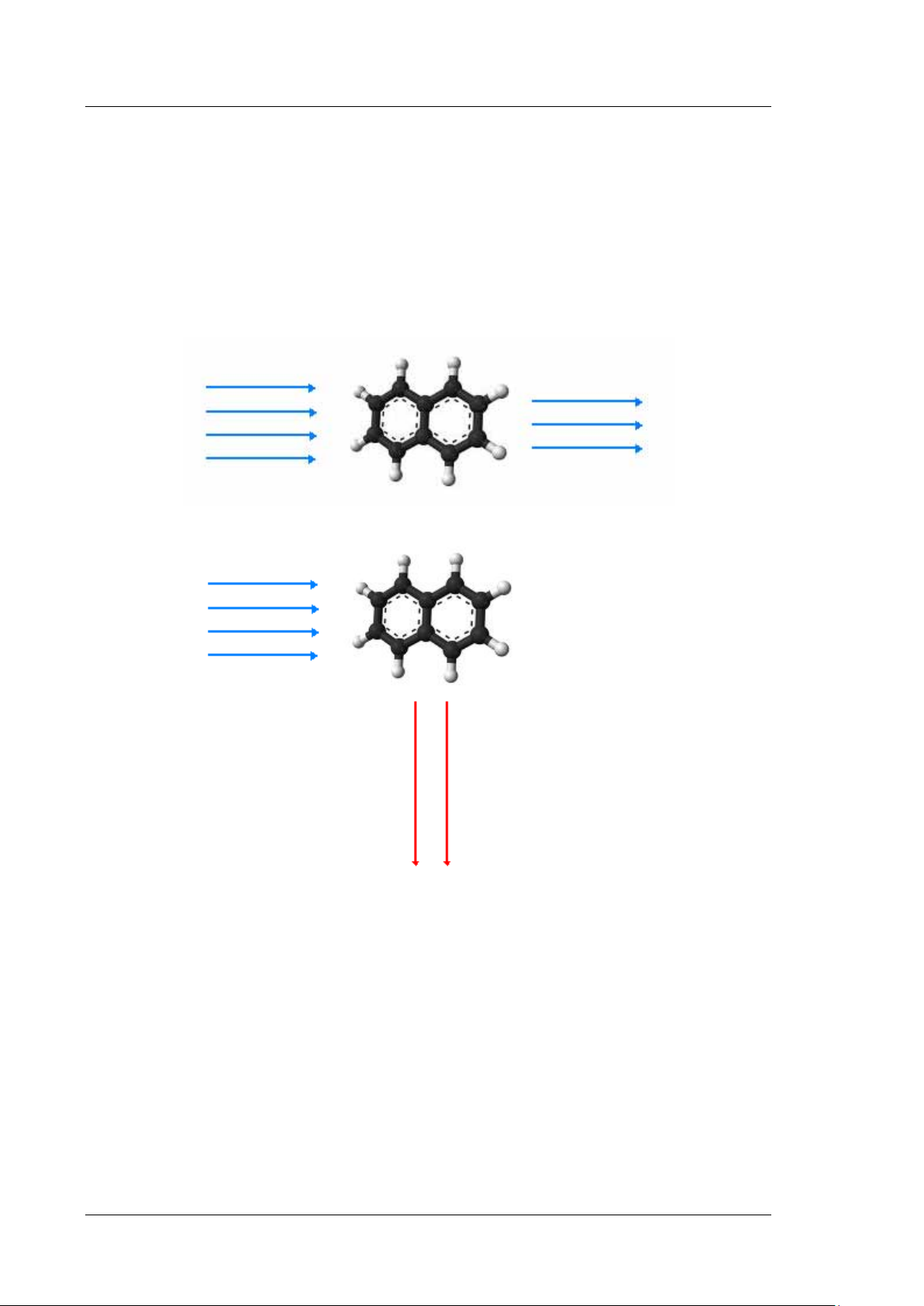
2.2 Operating Principle
Fluorescence detectors are optical detectors. In a fluorescence detector, the sample is
exposed to light at a defined wavelength (excitation). The thus excited sample substance
emits light at a higher wavelength (emission). The photomultiplier is positioned at an angle
of 90° to the light source and detects the light that was emitted from the fluorescing
substances. In contrast to UV/Vis detectors, a fluorescence detector measures a very weak
light signal rather than the difference between light intensities (absorbance).
Fig. 1: Simplified presentation of absorption in a molecule
light of a longer
wavelength
Fig. 2: Simplified presentation of the light emission in a molecule (fluorescence)
Fluorescence is used, for example, in highlighters or in whitening agents (optical
brighteners). Fluorescent paint used in highlighters reacts to the blue and near, non-visible
ultraviolet range of the daylight and gives off light at a longer wavelength (typically bluegreen, yellow and red).
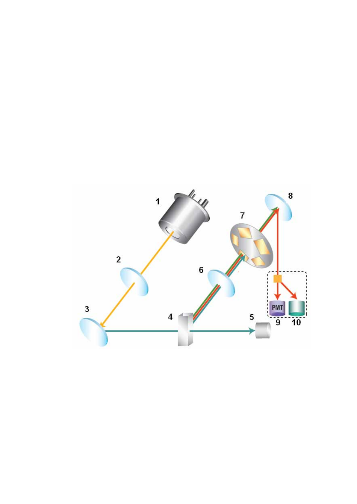
As shown in Fig. 3 (→ page 17), the light beam from the xenon lamp (no. 1) is focused by the
lamp optics (no. 2) through the entrance of the excitation monochromator (no. 3). The
excitation monochromator transmits only light of the user-selected wavelength to the sample
inside the flow cell (no. 4). Most of the light penetrates the sample. A reference detector
(no. 5) behind the flow cell measures the intensity of this light. The excitation light stimulates
the sample to emit fluorescence light.
Page 16 Operating Instructions
Page 25
UltiMate 3000 Series:
Fluorescence Detectors FLD-3100 and FLD-3400RS
When the light exits the flow cell, it is focused by the emission optics (no. 6) through the
emission monochromator (no. 8).
A cut-off filter, which lets only light above a certain wavelength pass, is located before the
emission monochromator. In the FLD-3100, the filter has a fixed cut-off wavelength
(280 nm). In the FLD-3400RS, a filter wheel (no. 7) is installed. With the help of a motor the
wheel can be moved to 5 different positions with different cut-off wavelengths. The selectable
filter helps to achieve an even better sensitivity and increase flexibility during method
development.
The emission monochromator transmits only the light with the user-selected emission
wavelength to a photomultiplier tube (PMT) (no. 9), where the light is measured. A second
optional red-sensitive photomultiplier tube (no. 10) measures light in the near infrared region
(up to 900 nm).
Fig. 3: Optics setup (schematic)
Operating Instructions Page 17
Page 26

UltiMate 3000 Series:
Fluorescence Detectors FLD-3100 and FLD-3400RS
No. Component Description
1 Xenon lamp Light source for the UV to near-infrared wavelength range
2 Lamp optics Receives the light beam emitted from the xenon lamp and focuses it so
that the beam passes through the excitation monochromator.
3 Excitation
monochromator
4 Flow cell The eluent with the analyte travels through the flow cell. The excitation
5 Reference detector Measures the excitation light intensity though the flow cell.
6 Emission optics Receives the light beam emitted from the flow cell and focuses it so that
7 Filter wheel Carries the optical filter, which is used to cut off light up to a certain
8 Emission
monochromator
9 PMT Photomultiplier tube (PMT) - Converts the emitted light to a
10 Second PMT (Optional) A second red-sensitive photomultiplier tube measures light in
Lets only light with the selected excitation wavelength pass.
light passes through the flow cell to the reference detector, the
fluorescence light exits the flow cell at an angle of 90° to the excitation
light.
the beam passes through the emission monochromator.
wavelength. The FLD-3400RS provides five filter positions with
different cut-off wavelengths.
Lets only light with the selected emission wavelength pass.
measureable current signal.
the near infrared region (up to 900 nm).
Page 18 Operating Instructions
Page 27

UltiMate 3000 Series:
Fluorescence Detectors FLD-3100 and FLD-3400RS
2.3 Configurations
The detector is available in the following configurations:
Detector Description Part no.
FLD-3400RS detector for measurements up to 200 Hz*. Up to four
5078.0020
wavelengths can be recorded simultaneously.
FLD-3400RS detector with Dual-PMT 5078.0025
FLD-3100 detector for measurements up to 100 Hz. However, only
5078.0010
one wavelength can be recorded.
FLD-3100 detector with Dual-PMT 5078.0015
*Only with Chromeleon 7.1 or later
Dual-PMT
The variants of the FLD with Dual PMT are equipped with a second PMT for the near
infrared region (up to 900 nm) (→ no. 10, Fig. 3, page 17). Depending on the PMT setting,
the instrument selects the suitable PMT for each measurement, or you can manually select
which PMT should be used. For emission scans, you can scan with both PMTs
simultaneously.
Detectors with a single PMT can later be upgraded with a second PMT by the Thermo
Fisher Scientific Service for Dionex HPLC Products.
Operating Instructions Page 19
Page 28
UltiMate 3000 Series:
1
1
2
3
Fluorescence Detectors FLD-3100 and FLD-3400RS
2.4 Interior Components
The front panel door tilts downward to provide easy access to the inside front panel, for
example, for maintenance and repair work.
Important: The open front panel door is not designed to carry weight. Therefore,
you should not place any objects on the open front panel door.
Important: Ne placez aucun objet lourd sur la porte ouverte du panneau avant.
Ceci pourrait endommager la porte.
Fig. 4: Interior view from the front
No. Description
1
Slots in the enclosure to route the flow cell capillaries to the outside (→ page 23)
Two more slots with capillary guides are provided in the enclosure bottom.
2
Leak sensor (→ page 25)
3 Flow cell
No flow cell is installed when the detector is shipped. Before initial operation, install a flow cell.
Page 20 Operating Instructions
Page 29
1
2
3
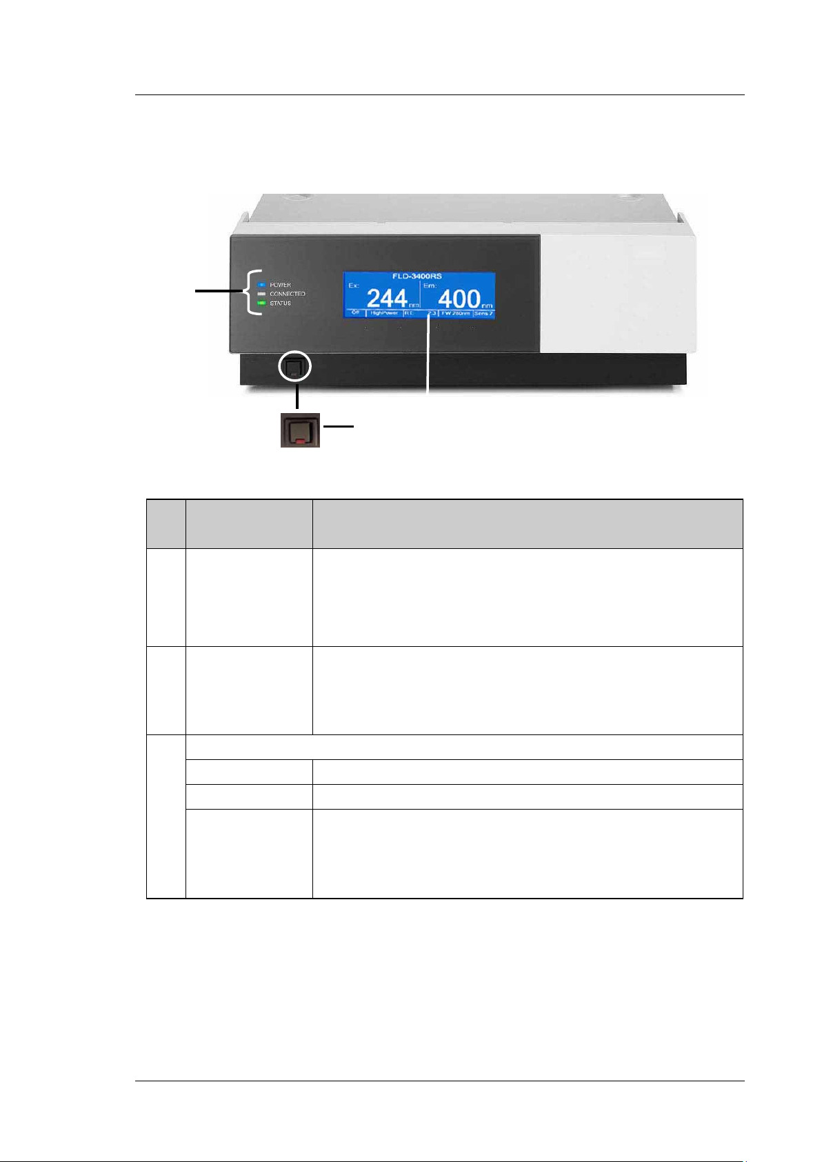
2.5 Front Panel Elements
UltiMate 3000 Series:
Fluorescence Detectors FLD-3100 and FLD-3400RS
Fig. 5: Front panel view
No. Front Panel
Element
1 Display
2 Standby button Switches the detector to Standby mode (the LED is lighted). To cancel
3
LEDs
Power The LED is blue when the detector is on.
Connected The LED is green when the detector is controlled by Chromeleon.
Status The LED is red when an error has been detected, e.g. when the lamp has
Function
Shows information about the detector:
- General information upon power up (→ page 55)
- Status screen, depending on the operating mode (→ page 55)
- Various menus, accessible via the menu key (→ page 57)
- Messages (→ page 97)
Standby mode and resume operation, press the Standby button again (the
LED is not lighted).
Note: To allow the detector to change the mode, press the Standby button
for at least one second.
failed. In addition, the corresponding message appears on the front panel
display (→ page 97).
The LED is orange, for example, when the detector is booting.
Otherwise, the LED is green.
Operating Instructions Page 21
Page 30
UltiMate 3000 Series:
6
Fluorescence Detectors FLD-3100 and FLD-3400RS
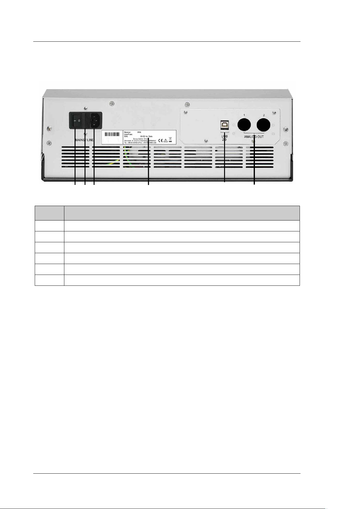
2.6 Rear Panel
1 2 5
3 4
Fig. 6: Rear panel
No. Description
1
2
3
4
5
6
Power switch (→ page 22)
Fuse cartridge (→ page 22)
Main power receptacle (→ page 34)
Type label
USB 2.0 (Universal Serial Bus) port for connection to the Chromeleon computer (→ page 23)
Analog outputs (optional, → page 34)
2.6.1 Power Switch
The power switch on the rear panel is the main power switch for the detector. Turn on the
power switch before initial operation of the detector and leave it on. For routine operation,
leave the main power switch on. For routine on/off control, use the standby button on the
front of the detector (→ page 21). Press and hold the button for about one second to allow
the detector to change the mode. Turn off the main power switch when instructed to do so,
for example, before performing a service procedure or when interrupting operation for
longer periods (one week or more). Observe the precautions on page 93.
2.6.2 Fuse Cartridge
The fuse cartridge contains two slow-blow fuses, rated at 2 A (5 x 20 mm). For
information about how to change the fuses, see page 114.
Page 22 Operating Instructions
Page 31

UltiMate 3000 Series:
Fluorescence Detectors FLD-3100 and FLD-3400RS
2.6.3 USB Port
The Chromeleon Chromatography Management System uses a USB connection to control
the detector. Data is transferred digitally via the appropriate USB cable (→ page 32). The
PC must be equipped with a USB port. To ensure trouble-free operation, use only the
cables shipped with the detector.
For information about how to connect the detector to the Chromeleon computer, see
sections 3.4.1 and 3.4.2 (→ page 32).
2.6.4 Analog Outputs (Optional)
If the optional DAC plug-in module (part no. 6078.0305) is installed, two analog outputs
with a resolution of 20 bits each are provided. The outputs can be connected to additional
evaluation devices. The analog output voltages are updated with the data rate selected in
Chromeleon (Data Collection Rate), however, not exceeding a maximum data rate of
50 Hz. For information about how to install the board, see page 34. For configuration
details, see page 36.
2.7 Fluid Connections
The detector is designed to provide easy access to the fluid components. Tilt the front
cover downward. At dedicated positions in the front part of the enclosure, six slots are
provided for the capillaries: on the top and bottom of the enclosure (two slots each), and on
the left and right side of the enclosure (one slot each) (→ Fig. 4, page 20).
Capillary guides on the bottom slots facilitate routing the capillaries to devices that are located
underneath the detector in the UltiMate 3000 system stack.
When closing the front panel door, avoid bending the capillaries and make sure that they are
routed to the outside through these slots.
Tip: The volume between the column and the flow cell should be as low as possible
to avoid peak broadening effects and the accompanying loss of
chromatographic efficiency. Preferably use Viper capillaries to prevent dead
volume.
Operating Instructions Page 23
Page 32

UltiMate 3000 Series:
Fluorescence Detectors FLD-3100 and FLD-3400RS
2.8 Flow Cells
The detector is shipped without a flow cell. The following flow cells are available for the
detector:
Volume
Heat exchanger
and/or inlet capillary
6.3 µL 6078.4230
3.3 µL 6078.4330
Part no.
Flow cell type
Analytical,
pressure limit: 20 bar
Micro,
pressure limit: 40 bar
Flow cell
material
Fused silica,
stainless steel,
PTFE
Fused silica,
stainless steel,
PTFE
Flow cell volume
8 µL,
Ø inlet capillary
0.18 mm
2 µL,
Ø inlet capillary
0.13 mm
All parts of the flow cell that are exposed to solvents are made of fused silica, stainless
steel, or PTFE (Polytetrafluorethylene).
All flow cells are optimized for fast separations with no loss in chromatographic
resolution. An identification chip is fitted to the flow cell in the factory. The chip stores
unique information about the flow cell, including the cell type and serial number. When the
flow cell is installed, a contact on the flow cell connects the chip to the detector
electronics.
The flow cells are equipped with a temperature control. Flow cell and heat exchanger can be
heated to a user-defined temperature (→ page 88). The heat exchanger helps to adapt the
temperature of the mobile phase to the flow cell temperature before the mobile phase enters
the optical part of the cell. Note that the volume of the heat exchanger and inlet capillary
indicated in the table influences the retention times and peak widths.
The micro flow cell is optimized for best resolution in UHPLC, and is recommended for use
with 2.1 mm ID columns. The analytical flow cell provides higher sensitivity and a better
signal-to-noise ratio with most other columns.
To ensure optimum performance of the flow cells, observe the guidelines (→ page 53).
Page 24 Operating Instructions
Page 33

UltiMate 3000 Series:
Fluorescence Detectors FLD-3100 and FLD-3400RS
2.9 Lamp
The light source is a xenon flash lamp with a power of 15W. The flash frequency of the
lamp varies, depending on the selected lamp mode.
The lamp is turned on when data acquisition starts, and automatically turned off after data
acquisition was stopped to extend its lifetime. It is not required that the lamp is turned on
during the entire chromatographic separation. For example; during re-equilibration of the
chromatographic column, usually no peaks of interest will elute. If you are not interested in
the baseline during the wash and re-equilibration phase, you can turn off the lamp by stopping
data acquisition, or set the lamp mode to a lower frequency. This will save lamp power on
time or reduce the number of lamp flashes, respectively, and thus extend the lamp lifetime. In
addition, you can extend the lamp lifetime by selecting a different lamp mode (→ page 88).
The lamp must be replaced only by Thermo Fisher Scientific Service for Dionex HPLC
Products.
2.10 Leak Sensor
A leak sensor (→ Fig. 4, page 20) is installed inside the detector. If liquid collects in the
drip tray under the fluid connections, the leak sensor reports a leak, and the Status LED on
the front panel door changes to red. In addition, a message appears on the front panel
display and in the Chromeleon Audit Trail and a beep alerts you. Leak sensor settings see
page 72.
When the leak sensor reports a leak, eliminate the cause for the leakage and dry the leak
sensor (→ page 113). If the sensor is not dry, the Status LED remains red. To remove the
message from the display, select Clear on the navigation bar.
Operating Instructions Page 25
Page 34

UltiMate 3000 Series:
Fluorescence Detectors FLD-3100 and FLD-3400RS
2.11 Detector Control
The detector can be controlled by the Chromeleon Chromatography Management System.
To operate the detector with Chromeleon, an appropriate Chromeleon version and the
corresponding license are required.
Tip: All software details in this manual refer to Chromeleon 6.80, unless stated
otherwise.
If you want to operate the detector with Chromeleon 7, refer to the following
documents for information about how to perform the related processes in
Chromeleon 7 (all documents are included in the Chromeleon 7 shipment):
• Chromeleon 7 Help—provides extensive information and comprehensive
reference material for all aspects of the software.
• Quick Start Guide—describes the main elements of the user interface and
guides you step-by-step through the most important workflows.
• Reference Card—provides a concise overview of the most important
workflows.
• Installation Guide—provides basic information about module installation
and configuration. For specific information about a certain module, refer
to the Chromeleon 7 Instrument Configuration Manager Help.
Note the following:
• Chromeleon 7 terminology is different from the terminology used in
Chromeleon 6.80. For details, refer to the Glossary, which is available in
the Documents folder of your Chromeleon 7 installation.
• Chromeleon 7 may not yet support all functions supported in
Chromeleon 6.80.
Two modes of software control are available:
• Direct Control
With direct control, you select operating parameters and commands in the Commands
(F8) dialog box. Direct commands are executed as soon as they are entered. For routine
operation, most parameters and commands are available also on a control panel. For
more information about direct control, see page 65.
• Automated Control
With automated control, you create a program (or PGM File). This is a list of control
commands, executed in chronological order, for automated operation of the detector.
Programs can be created automatically with the help of a software wizard or manually by
editing an existing program. For more information about automatic control, see page 67.
Page 26 Operating Instructions
Page 35

UltiMate 3000 Series:
Fluorescence Detectors FLD-3100 and FLD-3400RS
2.12 System Wellness, Predictive Performance, and Diagnostics
System Wellness monitors the health of the detector. Therefore, the detector supports
several performance and reliability features that can help you detect small problems before
they turn into big ones:
• Internal monitoring of all mechanical operations
• Automatic self test upon power up
• Monitoring the lamp age (→ page 108)
• Flow cell identification and documentation of the flow cell type (→ page 63)
• Leak sensor (→ page 25)
• General information for detector diagnostics (→ page 63)
When an error is detected, the Status LED on the front panel is red and a message appears on
the detector display (→ page 98).
In Chromeleon, additional functions for estimating the lifetime of consumables and
monitoring and recording service and (re)qualification information (= predictive performance;
→ page 92) are available to check the performance of the UltiMate 3000 system and certain
system components, and the overall performance of the instrument.
Operating Instructions Page 27
Page 36

UltiMate 3000 Series:
Fluorescence Detectors FLD-3100 and FLD-3400RS
Page 28 Operating Instructions
Page 37

UltiMate 3000 Series:
Fluorescence Detectors FLD-3100 and FLD-3400RS
3 Installation
3.1 Facility Requirements
The installation site must meet the following requirements:
• The main power switch and the main power receptacle are on the rear panel. Make sure
that
♦ Free and unrestricted access to the main power switch is ensured at all times.
♦ The power cord of the device can be easily reached and disconnected from the power
line at all times. Provide sufficient space behind the device to unplug the cable.
• Make sure that the installation site meets the power and environmental specifications
listed in the Technical Information section (→ page 117).
• Install the detector in the laboratory on a stable surface that is free of vibrations.
• Make sure that the surface is resistant to solvents.
• Avoid locations with extreme changes in temperature.
• Avoid direct sunlight and high humidity.
• Allow sufficient clearance behind and to the sides of the detector for ventilation.
Operating Instructions Page 29
Page 38

UltiMate 3000 Series:
Fluorescence Detectors FLD-3100 and FLD-3400RS
3.2 Unpacking
All electrical and mechanical components of the detector are carefully tested before the
instrument is shipped from the factory. After unpacking the detector, inspect the module
for any signs of mechanical damage, which might have occurred during transit.
Tips: Immediately report any shipping damage to both, the incoming carrier and
Thermo Fisher Scientific. Shipping insurance will compensate for the damage
only if reported immediately.
Keep the original shipping container and packing material. They provide
excellent protection for the instrument in case of future transit. Shipping the
unit in any other packaging automatically voids the product warranty.
1. Place the shipping container on the floor and remove the accessories kit and the power
cord.
2. Grasp the detector by the sides. Slowly and carefully, pull the instrument out of the
shipping container and place it on a stable surface.
Important: To prevent the device from falling, grasp the device by the
sides, and then lift the unit together with the foam spacers out
of the shipping container. Do not lift the unit by the
packaging material or the front panel.
Important: Afin d'empêcher l'instrument de tomber, saisissez-la par les
côtés. Ne soulevez l'instrument à l’aide du matériau
d'emballage ou par la porte du panneau avant.
3. Remove the foam spacers, and then remove the polythene packaging.
4. Before connecting the detector to the power source, wait approximately 4 hours to
allow the instrument to come to room temperature and to allow any condensation that
might have occurred during shipping to evaporate. After 4 hours, check the detector; if
condensation still exists, allow the detector to continue to warm up (without
connecting it to the power source) until the condensation is completely gone.
Page 30 Operating Instructions
Page 39

UltiMate 3000 Series:
Fluorescence Detectors FLD-3100 and FLD-3400RS
3.3 Positioning the Detector in the UltiMate 3000 System
If the detector is part of an UltiMate 3000 system, for example, for analytical HPLC
applications, you should stack the individual modules. However, the arrangement of the
system modules depends on the application.
• In a standard system with only one detector, where all modules are stacked, the
fluorescence detector is always the bottom module.
• In a system that includes a UV detector in addition to the fluorescence detector, the
modules can be arranged as shown in Fig. 7.
Fig. 7: Module arrangement for an UltiMate 3000 RS system with two detectors (example)
Left from top to bottom: SR-3000 solvent rack, LPG-3400RS pump, WPS-3000TRS
autosampler
Right from top to bottom: FLD-3400RS fluorescence detector, UV detector
(VWD-3400RS or DAD-300RS), TCC-3000RS thermostatted column compartment
Tip: As the flow cell of the fluorescence detector has a pressure limit of 20 bar
(analytical flow cell) or 40 bar (micro flow cell), the fluorescence detector
must always be the last module in the fluidic path.
Refer to section 3.4.2 for information how to connect the USB ports on the rear panels.
Operating Instructions Page 31
Page 40

UltiMate 3000 Series:
Fluorescence Detectors FLD-3100 and FLD-3400RS
3.4 Connecting the Detector
3.4.1 General Information
Verify that Chromeleon is installed on the computer and that the license code is entered
before you connect the detector to the USB port on the Chromeleon computer and turn on
the detector power. Only if you install Chromeleon first, the detector is connected to the
computer and the USB driver for the detector is automatically loaded. The Windows®
operating system can detect the detector when the power is turned on.
3.4.2 Connecting the USB Cable
Connect the detector to the Chromeleon computer via the USB port on the rear panel.
Select one of the following alternatives:
• Connect the detector directly to the USB port on the computer.
• Connect the detector to an internal USB port on the pump. Thermo Fisher Scientific
recommends connecting all modules to the pump, and then connecting the system to the
Chromeleon computer via only one connection (→ Fig. 8, page 33). If the system
includes a UV detector in addition to the fluorescence detector, Thermo Fisher Scientific
recommends connecting the UV detector directly to the Chromeleon computer.
Tip: The USB standard limits the USB cable length to 5 meters. Each USB device
can be separated from the PC or next USB hub by no more than 5 meters.
The following cable is available (provided in the accessories kit for the detector):
USB Cable Part no.
USB cable, type A to type B, high speed USB 2.0 (cable length: 5 m) 6911.0002
Page 32 Operating Instructions
Page 41

UltiMate 3000 Series:
Autosampler
Column
Pump
Solvent rack
Fluorescence
Fluorescence Detectors FLD-3100 and FLD-3400RS
compartment
detector
Fig. 8: Example for the rear panel connections on an UltiMate 3000 system
Operating Instructions Page 33
Page 42

UltiMate 3000 Series:
Fluorescence Detectors FLD-3100 and FLD-3400RS
3.4.3 Connecting the Power Cord
Use the power cord shipped with the device to connect the detector to the main power
source. No manual adjustment is required to adapt the line voltage to local voltage
requirements.
Warning: Never use a power cord other than the power cords provided for the
device.
Do not use multiple sockets or extension cords. Using defective
multiple sockets or extension cords may cause personal injury or
damage to the device.
Avertissement: Utilisez uniquement les cordons d’alimentation électrique spécifique
à l’instrument.
N'utilisez pas des blocs multiprise ou des câbles prolongateurs. Cela
pourrait entraîner des blessures corporelles ou endommager
l'instrument.
3.4.4 Connecting the Analog Outputs (Optional)
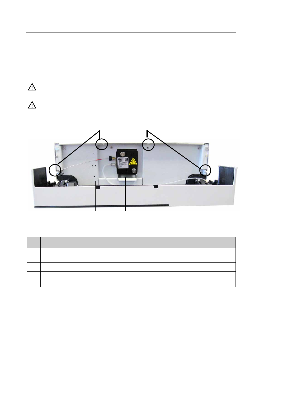
3.4.4.1 Installing the DAC Board
1. Turn off the detector and disconnect the power cord from its source.
2. Use appropriate grounding protection to avoid electrostatic discharge, which may
result in damage to electronic components.
3. Loosen the four screws indicated in Fig. 9 and remove the access panel from the rear
panel.
Fig. 9: Screws on the access panel
Page 34 Operating Instructions
Page 43

UltiMate 3000 Series:
Guide bar
USB port
Fluorescence Detectors FLD-3100 and FLD-3400RS
4. Slide the left guide bar of the DAC board onto the green edge next to the USB port.
Fig. 10: Installing the DAC board
5. Push the board partially into the enclosure. Apply slight pressure between the two
analog outputs to push the board further into the enclosure until it locks into position.
6. Attach the board to the rear panel, by using the 4 screws as shown in Fig. 9.
7. Connect the analog outputs to an evaluation device (→ page 35).
Tip: Installation of the DAC board does not require additional validation, such as
Operational Qualification or Performance Qualification.
3.4.4.2 Connecting an Analog Output to an Evaluation Device
1. Locate the analog output cable (part no. 6074.0002) provided with the DAC board.
Plug the cable connector into the analog output on the detector rear panel.
2. Connect the free end of the cable to the analog input on the evaluation device.
3. Make the required settings in Chromeleon (→ section 3.4.4.3).
Operating Instructions Page 35
Page 44

UltiMate 3000 Series:
Fluorescence Detectors FLD-3100 and FLD-3400RS
3.4.4.3 Configuring the Analog Outputs
Make the required settings for the analog outputs in Chromeleon.
1. On the Detector page in the Properties dialog of the detector, verify that the DAC
Board check box is selected (→ page 42). When the check box is cleared, the analog
outputs will not be available in Chromeleon.
2. Open the Commands dialog box for the detector.
3. Make the required settings.
Analog Output
Setting
Analog1_Channel
Analog2_Channel
Analog1_Offset
Analog2_Offset
Analog1_Range
Analog2_Range
Analog1_Voltage
Analog2_Voltage
Description
Sets the signal that is available at the analog output.
Adjusts the zero position of the analog output when it is plotted. The value
entered is a percentage of the full-scale analog output. The offset allows the
evaluation device to plot the signal if it becomes negative.
Even with a very small, positive analog output signal an offset of 5 %, for
example, should be set, because the minimum output voltage of the analog
output cannot be exactly 0 V.
Sets the value range, and thus the resolution of the analog output signal.
The range to use depends on the values expected for the application and the
evaluation device to which the output is connected.
Sets the maximum voltage value of the analog output signal (1 or 10). The
range to be used depends on the input voltage of the evaluation device to
which the output is connected.
Page 36 Operating Instructions
Page 45

UltiMate 3000 Series:
Fluorescence Detectors FLD-3100 and FLD-3400RS
3.5 Setting Up the Detector in Chromeleon
This section provides brief instructions for setting up the detector in Chromeleon. For
details, see the Chromeleon Help.
Tip: When the detector is connected to the Chromeleon computer, verify that the
Chromeleon software is installed before turning on the detector power for the
first time. Only then, the USB driver for the detector is automatically loaded
and the Windows operating system detects the detector when the power is
turned on.
3.5.1 Loading the USB Driver for the Detector
1. Turn on the computer power, if it is not already on.
2. Under Windows Vista® (Windows® XP, Windows® 7, or Windows® Server 2008) log
on as a
• Local administrator if the computer is a local computer.
• User with local computer administrator privileges if the computer is a network
computer.
3. Open the Chromeleon Server Monitor program by double-clicking the Chromeleon
Server Monitor icon on the Windows taskbar.
If the Server Monitor icon is not on the taskbar, click Start on the taskbar, point to
Programs (or All Programs, depending on the operating system), point to Chromeleon,
and then click Server Monitor.
4. Click Start to start the server.
5. Click Close to close the Server Monitor window. The Server Monitor icon
appears on the taskbar.
Tip: Clicking the Quit Monitor button quits (exits) the Server Monitor
program, but does not stop the server. To stop the server, click Stop.
6. Turn on the main power switch on the rear panel of the detector.
Operating Instructions Page 37
Page 46

UltiMate 3000 Series:
Fluorescence Detectors FLD-3100 and FLD-3400RS
7. Windows Vista, Windows 7, and Windows Server 2008
will automatically detect the new detector and perform the USB installation.
If Windows fails to detect the detector and launches a wizard instead, this indicates that
you connected the detector to the computer and turned on the power for the first time
before you installed Chromeleon. To resolve the problem:
a) Click Cancel to exit the wizard.
b) Turn off the detector.
c) Install Chromeleon.
d) Turn on the detector power. Windows will now detect the detector and install the USB
software for the detector automatically.
Windows XP
will automatically detect the new detector and launch the Found New Hardware
Wizard, which guides you through the USB installation. Select the following options:
a) If asked whether Windows can connect to Windows Update to search for software,
select No, not this time.
b) Accept the default option (Install the software automatically) and click Next>.
c) Click Finish when the wizard reports that the software for the detector has been
installed.
If Windows XP fails to detect the detector and a message box asks for a USB
configuration file (cmwdmusb.inf), this indicates that you connected the detector to
the computer and turned on the power for the first time before you installed
Chromeleon. To resolve the problem:
a) Click Cancel in the Windows message box.
b) Turn off the detector.
c) Install Chromeleon.
d) Turn on the detector power. Windows will now automatically detect the detector and
launch the Found New Hardware Wizard.
Page 38 Operating Instructions
Page 47

UltiMate 3000 Series:
Fluorescence Detectors FLD-3100 and FLD-3400RS
3.5.2 Installing the Detector
After the USB software for the detector has been installed (→ page 37), install and
configure the detector in Chromeleon:
1. Start the Chromeleon Server Monitor (→ page 37) and the Chromeleon server if they
are not yet running.
2. Start the Chromeleon Server Configuration program by clicking Start on the taskbar.
Point to Programs (or All Programs, depending on the operating system), point to
Chromeleon, and then click Server Configuration.
3. If necessary, click the plus sign next to the server name to display the items
underneath.
4. Select the timebase to which the detector will be assigned, or create a new timebase
(on the Edit menu, click Add Timebase).
5. Open the Add device to timebase dialog box. To do so, click Add Device on the Edit
menu or right-click the timebase and click Add Device on the menu.
6. On the Manufacturers list, click Dionex HPLC: UltiMate 3000 and on the Devices
list, click FLD-3x00(RS) Detector.
7. The configuration pages are opened. On each page, verify that the settings are correct
and select additional settings if needed. For a description of the pages, see
section 3.5.3.1.
8. Click OK to complete the configuration of the detector.
9. On the File menu, click Save Installation and then close the Server Configuration
program.
Operating Instructions Page 39
Page 48

UltiMate 3000 Series:
Fluorescence Detectors FLD-3100 and FLD-3400RS
3.5.3 Configuring the Detector
3.5.3.1 Initial Installation
During the installation, Chromeleon connects to the detector and transfers the settings from
the instrument firmware to Chromeleon, setting the options on the wizard pages
accordingly. Verify that the settings are correct and make additional settings if needed.
You may reopen the configuration pages later again to change the settings (→ page 43).
Tip: Changing the settings for a specific application in the Commands dialog box,
in a program file (PGM), or on a control panel will not change the default
settings on the configuration pages.
For additional information about a page, click Help.
General Page
Shows the general instrument parameters.
Fig. 11: General page
• Virtual Mode
Verify that the virtual mode is set to off. If the virtual mode is enabled, the Module
Address box will be unavailable. If you exit this page without having entered a module
address, the virtual mode will be enabled automatically.
In the virtual mode, Chromeleon simulates detector control and data acquisition.
♦ Click Read to read and display data from an existing demo file instead of real data.
Select the file from the Virtual Mode File Name list.
Page 40 Operating Instructions
Page 49

UltiMate 3000 Series:
Fluorescence Detectors FLD-3100 and FLD-3400RS
♦ Click Write to save the data currently delivered by the detector as a demo file. Enter
the file name in the Virtual Mode File Name field or select a name from the list.
Tip: When recording virtual mode files in Chromeleon 6.80, the size of the file
is limited to 35MB. This corresponds to about 9 minutes at a data
collection rate of 100 Hz. If you want to record longer virtual mode files,
reduce the data collection rate.
• Module Address
Select the module address of the detector. Click Browse and then double-click the
detector that you want to use on the Device List. The address is automatically entered in
the Module Address field. Chromeleon connects to the detector and transfers the settings
from the instrument firmware to Chromeleon, setting the options on the pages
accordingly. Confirm the related message with OK.
• Download
Click this button to transfer the current detector configuration to Chromeleon. (The
button appears dimmed if the virtual mode is enabled.)
The detector is shipped with the most recent firmware version. If a firmware update is
ever required, follow the steps in section 7.6 (→ page 115).
Operating Instructions Page 41
Page 50

UltiMate 3000 Series:
Fluorescence Detectors FLD-3100 and FLD-3400RS
Detector Page
The Detector page shows the detector configuration.
Fig. 12: Detector page
• FLD Type
Select the detector type. Make sure that the selected option corresponds to the actually
installed detector type.
• Device Name
Displays the name used to identify the detector the installation environment and in the
Chromeleon client program. To control the detector with the existing control panels,
accept the default name. If you enter a different name, you may have to re-link the
controls on the control panels and edit the device name in the program files.
• 2nd PMT
This check box must be selected if the optional red-sensitive Dual-PMT option for
measuring wavelengths up to 900 nm is installed.
• DAC Board
This check box must be selected if optional analog output are installed. (→ page 34)
Page 42 Operating Instructions
Page 51

UltiMate 3000 Series:
Fluorescence Detectors FLD-3100 and FLD-3400RS
Signals Page
The page lists all signal channels that the detector can record. A name is defined for each
channel. To allow raw data collection for a channel, select the Enabled check box next to
the channel name. If the check box is cleared, the detector cannot collect raw data for the
channel. To change a name, click in the field and overwrite the existing name directly in
the field.
Fig. 13: Signals page (here: FLD-3400RS)
3.5.3.2 Changing the Configuration Properties
You may reopen the configuration pages later again to change the settings.
1. Start the Server Configuration program (→ page 39).
2. Right-click FLD-3x00(RS) Detector in the timebase and click Properties on the
menu.
3. Change the settings as needed. For a description of the pages, see section 3.5.3.1
(→ page 40).
4. To save the changed configuration, click Save on the File menu and then close the
Server Configuration program.
Operating Instructions Page 43
Page 52

UltiMate 3000 Series:
Fluorescence Detectors FLD-3100 and FLD-3400RS
3.6 Setting Up the Detector in DCMSLink
To set up the detector in DCMSLink, refer to DCMSLink Installation Guide, which is
provided on the DCMSLink DVD in the Additional Documents\DCMSLink User
Documents folder.
1. Install and configure the DCMSLink software (→ DCMSLink Installation Guide).
2. Open the Chromeleon Server Configuration program (→ DCMSLink Installation
Guide).
3. In the Server Configuration program, add the detector to the timebase. The steps in
section 3.5.2 apply equally (→ page 39).
4. Configure the detector. The steps in section 3.5.3 apply equally (→ page 40).
For more information about DCMSLink, refer to the DCMSLink Quick Start Guide, which is
also provided on the DCMSLink DVD and to DCMSLink Help.
Page 44 Operating Instructions
Page 53

UltiMate 3000 Series:
Fluorescence Detectors FLD-3100 and FLD-3400RS
4 Preparation for Operation (Startup)
4.1 Overview
After you have unpacked, positioned and connected the detector as described in sections
3.1 through 3.5 (→ page 29 and following), prepare the detector for operation. Follow the
sequence of steps below:
1. No flow cell is installed when the detector is shipped. Install a flow cell (→ page 110)
and connect the cell inlet connection to the separator column outlet. Connect a waste
capillary to the flow cell outlet.
2. Connect the drain tubing (→ page 47).
3. Set up the detector in Chromeleon if it is not already set up (→ page 37).
4. Check and change the leak sensor setting if necessary (→ page 72).
5. Adjust the brightness and contrast of the detector display if necessary (→ page 72).
6. If you want to connect additional evaluation devices to the detector
Install the DAC plug-in board and configure the analog outputs (→ page 34).
7. Before using the module for sample analysis, equilibrate the entire system
(→ page 51).
Operating Instructions Page 45
Page 54

UltiMate 3000 Series:
Fluorescence Detectors FLD-3100 and FLD-3400RS
4.2 General Precautions for Connecting Capillaries
When connecting capillaries, observe the following general precautions:
• Observe the precautionary statements for capillaries and capillary connections in
section 1.2.2 (→ page 5).
• UltiMate 3000 systems with stainless steel fluidics are shipped with Viper capillary kits.
The kits include a Viper capillary for connecting the detector to the separation column
when the system includes only one detector. For UltiMate 3000 RSLC systems, you can
use the post column cooler to connect the detector to the column as an alternative. This is
recommended if you are operating the column at temperatures above 60°C, as high
temperatures may reduce the intensity of the fluorescence signal.
• If you are using more than one detector in a system, for example, a UV detector and a
fluorescence detector, another Viper capillary is available in the flow cell accessories.
• If possible, use a Viper capillary between the column and the detector. In rare cases, this
may not be possible for columns from third-party manufacturers. Always make sure that
the ID of replacement capillary corresponds to the ID of the capillary shipped with the
system.
• Depending on the fitting connection, also observe the following:
♦ Viper fitting connections
Loosen or tighten the Viper connection only using the black knurled screw and only
with your hand (do not use tools). The knurled screw can be easily removed and
reattached to the capillary at any time. Viper capillaries are designed to be leak-free
for all pressures that arise in UltiMate 3000 systems simply by tightening them with
your hand. If you observe leakage on the connection, tighten the screw a little further.
If leakage continues, remove the capillary, clean the capillary ends carefully by using
a cloth or tissue wetted with isopropanol, and reinstall the capillary. If the connection
continues to leak, replace the Viper capillary.
When connecting the Viper capillary to the flow cell inlet, observe the guidelines in
the Installation Instructions shipped with the capillary.
Capillaries with Viper fitting connections can be reused also for a different
connection.
Page 46 Operating Instructions
Page 55

UltiMate 3000 Series:
Drain port
Fluorescence Detectors FLD-3100 and FLD-3400RS
♦ Conventional fitting connections (non-Viper)
Do not over-tighten these fitting connections. If you observe leakage on the
connection, tighten a little further.
If leakage still exists, first consider cleaning the connection port with a cleaning swab
(part no. 6040.0006). Replace the capillary and/or fitting if this does not eliminate the
problem.
Reuse used fittings and ferrules only for the same capillary connection. This is to
avoid increased dead volume or damage to the system and leakage
4.3 Connecting the Drain System
To discharge liquid leaks and waste, the detector has a drain port at the bottom right of the
instrument.
Fig. 14: Drain port
Direct liquid leaks to waste via the drain system of the UltiMate 3000 system, using the
components from the drain kit. The kit is shipped with the UltiMate 3000 pumps and can
be ordered separately (part no. 6040.0005). The kit includes all required components and
detailed installation instructions. If there is more than one detector in your system and you
need an additional tee piece, you can find one in the accessories kit of the fluorescence,
multiple wavelength, or diode array detector.
Operating Instructions Page 47
Page 56

UltiMate 3000 Series:
Flow cell body
Fluorescence Detectors FLD-3100 and FLD-3400RS
4.4 Installing the Flow Cell
Observe the following when installing a flow cell:
• Always hold flow cells by the flow cell body with the type label. Do not touch the optical
block of the flow cell (→ Fig. 15) or the sensitive electronics on the flow cell rear side.
Optical block
Fig. 15: Flow cell of the fluorescence detector
• A cover is mounted on the flow cell opening when the detector is shipped. Keep this
cover in a safe place. If the detector is shipped or shut down for a longer time period,
reinstall the cover.
• Plugs are installed at the flow cell in and out connections (→ Fig. 19). Keep the plugs in
a safe place. If the detector or the cell is shipped or if the detector is shut down for a
longer time period, reinstall the plugs.
• Capillary connections between the column and flow cell should be as short as possible to
avoid peak broadening effects due to excessive dead volume.
• When connecting the flow cells, make sure not to invert input and output. This will
deteriorate the measured results and may destroy the flow cell due to the increased
backpressure in the cell.
Page 48 Operating Instructions
Page 57

UltiMate 3000 Series:
Knurled screws of the
Fluorescence Detectors FLD-3100 and FLD-3400RS
• The backpressure on the flow cell must not exceed 20 bar (analytical flow cell) or 40 bar
(micro flow cell). Do not connect any capillaries or instruments to the flow cell out line
as this might generate a higher backpressure. Even if the pressure exceeds the upper limit
for a very short time only, the flow cell may be permanently damaged. If it is required to
connect a valve at the flow cell outlet, the valve may only be switched while the flow is
stopped. When switching valves while the flow is turned on, pressure peaks may occur
and destroy the flow cell. Thermo Fisher Scientific recommends using a capillary or tube
with an internal diameter of at least 0.5 mm at the flow cell out line.
Installing the Flow Cell
1. Remove the cover on the flow cell opening (if installed). To do so, loosen the two
finger-tight screws. No tools are required to loosen the screws. The screws are captive
in the cover and do not need to be removed.
Fig. 16: Removing the cover
flow cell opening cover
Operating Instructions Page 49
Page 58

UltiMate 3000 Series:
Fluorescence Detectors FLD-3100 and FLD-3400RS
2. Insert the flow cell straight into the cell opening.
Fig. 17: Inserting the flow cell
3. Tighten the flow cell screws hand-tight.
Flow cell screws
Fig. 18: Tighten the flow cell screws
4. Remove the dummy plugs at the flow cell in and out connection ports. Connect the
flow cell inlet to the separation column. Connect the PEEK capillary from the
accessories kit for the detector as waste capillary to the flow cell outlet. Extend the
PEEK capillary with the silicone tubing (also included in the accessories kit for the
detector). Route the capillaries to the outside through the slots provided in the detector
enclosure to prevent them from being pinched when the front panel door is opened.
5. Close the front panel door to allow the firmware to detect the new flow cell.
6. Perform a wavelength calibration (→ page 90).
Page 50 Operating Instructions
Page 59

UltiMate 3000 Series:
Fluorescence Detectors FLD-3100 and FLD-3400RS
4.5 Equilibrating the System
Before using the detector for sample analysis, equilibrate the UltiMate 3000 system:
1. Pump the starting solvent through the entire system until the system is free of any
other liquid composition.
2. Heat or cool all temperature-controlled devices, such as the column oven, to the
temperature required for the application.
3. Heat the flow cell of the fluorescence detector to the required temperature.
4. If a UV detector is installed: Set the detector wavelengths and turn on the lamp.
5. Monitor the pump pressure. Verify that the reading is correct for the application and is
stable.
6. Monitor the UV detector signal and verify that the baseline signal is at the expected
reading for your application and is stable.
Perform system equilibration in Chromeleon or select the required commands and
parameters on the front panel menus of the instruments.
To equilibrate the system from Chromeleon
• Select and perform the operating commands and parameters from the Commands dialog
box.
• Create and run an equilibration program to automate the process (→ page 67).
• Use the SmartStartup Wizard to create and run the equilibration program (see the next
section).
To create the equilibration program with the SmartStartup Wizard
1. To open the wizard, select SmartStartup on the Batch menu.
2. Follow the instructions as they appear on each page of the wizard. For additional
information about a page, click Help.
3. After you finish the wizard, Chromeleon
♦ Generates an equilibration program and sequence.
♦ Opens the equilibration control panel for the instruments in the timebase.
♦ Opens the Start Batch on dialog box.
Click Start to begin equilibration.
The equilibration panel shows the equilibration status of each instrument in the system.
Operating Instructions Page 51
Page 60

UltiMate 3000 Series:
Fluorescence Detectors FLD-3100 and FLD-3400RS
4.6 General Guidelines for Detector Operation
The following sections offer general guidelines for detector operation. For information
about how to optimize the detector performance, see section 5.7 (→ page 77).
4.6.1 Mobile Phases
Mobile phase quality significantly affects detection limits and instrument performance. To
ensure optimal performance of the detector, observe the following guidelines:
• Prepare all mobile phases with HPLC-grade (or better) solvents, reagent-grade chemicals,
and filter HPLC-grade water. Usually, HPLG-grade solvents will provide good results.
As impurities in the solvents increase the baseline noise, you should use special
fluorescence-grade solvents, for example LiChrosolv®, for sensitive applications. Always
use fluorescence-grade solvents and water for Raman tests and instrument qualification.
• Degas all mobile phases before use and maintain them in a degassed state.
• Strong bases can etch the silica windows of the flow cell. Therefore, avoid the use of
mobile phases with a pH value > 9.5. In any case, disconnect the separation column and
flush the system with HPLC-grade water for 5°minutes at 1.0°mL/min immediately after
the analysis when alkaline solutions are used.
• Mobile phase pH affects not only the retention time of the separation, but the
fluorescence intensity and wavelength of the sample.
• When changing from a buffer to a different operating mobile phase, be sure the solvents
are miscible and will not induce precipitation of the buffers. Flush the cell with a buffercompatible solvent (in most cases, HPLC-grade water) immediately after the analysis. Do
not allow buffers to remain in the cell for extended periods.
For information about the properties of common used mobile phases, see section 10 in
Table 1 (→ page 123).
Page 52 Operating Instructions
Page 61

UltiMate 3000 Series:
Fluorescence Detectors FLD-3100 and FLD-3400RS
4.6.2 Mobile Phase Delivery System
The pumping system should deliver continuous flow while ensuring intermixing of the mobile
phase (if gradient elution is used). Fluctuations in pump backpressure can cause baseline
noise. If the noise is synchronized with the pump stroke, check your HPLC pump.
The plastics present in some solvent delivery systems from third-party manufacturers are not
fully compatible with the solvents commonly used in chromatography. Therefore, plastic
components may dissolve, and thus impair fluorescence detection.
For UV wavelengths, these guidelines are recommended:
• The mobile phase reservoir should be glass.
• All tubing connections should be made of materials suitable for HPLC applications (for
example, PTFE, ETFE, PEEK, stainless steel, or titanium), as required for the operating
pressures and application.
• Some pump seals incorporate a band spring to preload the seal during the vacuum stroke
of the piston. The band spring should be made of stainless steel, a fluoropolymer
(perfluoroelastomer or fluorosilicone), or another material of known quality.
If you are working with an UltiMate 3000 system, using original Dionex parts only, all the
above recommendations are met.
4.6.3 Flow Cells
To ensure optimum performance of the flow cells, observe the following guidelines:
• The backpressure on the flow cell must not exceed 20 bar (analytical flow cell) or 40 bar
(micro flow cell). Do not connect any capillaries or instruments to the flow cell out line
as this might generate a higher backpressure. Even if the pressure exceeds the upper limit
for a very short time only, the flow cell may be permanently damaged. If it is required to
connect a valve at the flow cell outlet, the valve may only be switched while the flow is
stopped. When switching valves while the flow is turned on, pressure peaks may occur
and destroy the flow cell. Thermo Fisher Scientific recommends using a capillary or tube
with an internal diameter of at least 0.5 mm at the flow cell out line.
• When connecting the flow cells, make sure not to invert input and output. This will
deteriorate the measured results and may destroy the flow cell due to the increased
backpressure in the cell.
• The contacts for the flow cell identification chip and the temperature control are located
on the rear of the flow cell. To ensure proper functionality, be careful not to touch the
sensitive electronics. If liquid comes into contact with the electronics, dry it immediately.
Operating Instructions Page 53
Page 62

UltiMate 3000 Series:
Fluorescence Detectors FLD-3100 and FLD-3400RS
• The flow cells are sensitive to dirt and dust. Therefore:
♦ Always keep unused flow cells in their original dust-free packaging.
♦ Always hold flow cells by the flow cell body with the type label. Do not touch the
optical block of the flow cell (→ Fig. 15, page 48).
♦ Even during periods of detector inactivity, a flow cell or the cover shipped with the
detector must be installed. This is to prevent dust particles from causing damage to the
detector optics.
♦ When shipping the instrument, remove the flow cell and install the special cover to
protect the flow cell opening. Close the flow cell inlet and outlet with the plugs that
were installed when the flow cell was shipped (→ Fig. 19). The flow cell must be
shipped in its original packaging.
Fig. 19: Original Dionex flow cell plugs
• During longer idle times, the flow cell should not be filled with pure water to avoid the
growth of algae. Add 10% HPLC-grade isopropyl alcohol, for example, and plug the
flow cell input and output using the plugs that were installed when the flow cell was
shipped (→ Fig. 19). Using different plugs and tightening them may destroy the flow
cell.
• If a flow cell leaks, remove the flow cell from the detector as quickly as possible, and
replace the flow cell.
• For information about how to clean a flow cell, see page 109.
Page 54 Operating Instructions
Page 63

UltiMate 3000 Series:
Sens 7
Off
244
nm
400
nm
Ex:
Em:
FLD-3400RS
HighPower
FW 280nm
RT: 2.3
Fluorescence Detectors FLD-3100 and FLD-3400RS
5 Operation and Maintenance
The detector can be controlled by the Chromeleon Chromatography Management System.
For details, see section 5.4 (→ page 64) and the following.
5.1 Power-Up
To start the detector for the first time, turn on the main power switch on the rear panel of
the detector. The following sequence of events occurs when the detector is powered up
• For a short time, general information about the detector appears on the display: device
type, firmware version, and serial number.
• The detector runs a series of internal tests. (The test takes about 30 seconds.) During
these self-diagnostics, all of the main components are checked. When the self test was
successful, the initial screen changes to the status screen (→ page 55).
• If an error is detected, the detector is not ready for analysis. The Status LED on the front
panel is red and a message appears on the front panel display. If the detector is operated
with Chromeleon, the message appears also in the Chromeleon Audit Trail. Turn off the
detector, take appropriate remedial action (→ page 97), and turn on the detector again.
• If the message "Not calibrated" appears, verify that a flow cell is installed and execute the
Calibrate command in Chromeleon.
For routine operation, leave the main power switch on. For routine on/off control, use the
standby button on the front of the TCC (→ page 21). Press and hold the button for about
one second to allow the detector to change the mode. Turn the main power switch off when
instructed to do so, for example, before performing a service procedure.
5.2 Detector Display
When the self test was successful, the initial screen changes to the status screen.
Fig. 20: Status screen (example)
You can adjust the screen brightness or screen contrast to your requirements from
Chromeleon or on the detector display (→ page 72).
Operating Instructions Page 55
Page 64

UltiMate 3000 Series:
Sens 7
Run
71289
@ wavelength
Ex 250 nm
Em 350 nm
FL
D-3400RS
HighPower
FW 280nm
RT:
2.3
HighPower
46843
FLD-3400RS
Ex 220 nm
Em 325 nm
25146
34352
MultiChannel
2:
4:
1:
3:
RT: 2.31
19272
Ex 225 nm
Em 315 nm
Ex 237 nm
Em 460 nm
Ex 244 nm
Em 400 nm
Fluorescence Detectors FLD-3100 and FLD-3400RS
View the progress of data acquisition on the detector display
After data acquisition was started via Chromeleon (AcqOn), you can monitor the progress of
data acquisition on the display. The display shows a scaled fluorescence value (in counts) at
the selected wavelength. The number of measurement channels determines the appearance of
the screen.
Fig. 21: Data acquisition screen (examples)
The status screen shows the following information:
• Fluorescence values
• Emission and excitation wavelength
• Operational Status
• Lamp mode
• Retention time
• Filter wheel setting and sensitivity (only in Single-Channel Mode)
Page 56 Operating Instructions
Page 65

UltiMate 3000 Series:
244
nm
400
nm
Ex:
Em:
FLD-3400RS
Menu
Fluorescence Detectors FLD-3100 and FLD-3400RS
5.3 Menus on the Detector Display
Via the menus that are available on the front panel display, you can make several settings
or access information directly from the detector.
For information about the menus, see section 5.3.1 (→ page 58).
Showing the menu key
Four white spots can be found on the front panel below the display. To show the keys,
touch the position of the utmost left spot on the display with the menu pen (part
no. 6300.0100). The menu pen is included in the accessories kit for the UltiMate 3000
autosampler.
Fig. 22: Showing the menu key
The menu key replaces the information in the bottom line of the status screen. Select the
utmost left spot again to call the main menu. If no key is selected, the bottom line of the
status screen is restored after about 5 seconds.
Fig. 23: Menu key
If the detector is connected with Chromeleon, settings that do not interfere with the
measurement, such as, the screen brightness or contrast, can still be changed from the
display.
Operating Instructions Page 57
Page 66

UltiMate 3000 Series:
1. Configuration
3. Service
1. Adjust Lamp
3. Flow Cell
1. Reset to factory defaults
2. Display & soft keys
3. Leak sensor mode
2. Diagnostics
1. System
2. Optics
4. Temperatures
Main
2. Service Level
3. Reset Lamp
4. Replace Temperature
Sensor
Fluorescence Detectors FLD-3100 and FLD-3400RS
5.3.1 Detector Menus
Fig. 24 shows an overview of the detector menus. For information about the general menu
layout and structure, see page 59. For information about the individual commands and
parameters, see sections 5.3.3 through 5.3.5 (→ page 61 and following pages).
Fig. 24: Detector menu structure
Page 58 Operating Instructions
Page 67

Fluorescence Detectors FLD-3100 and FLD-3400RS
∧
> Main (1..3)
1. Control
2. Diagnostics
3. Service
∨
Select
Back
1
2
3
5.3.2 General Menu Layout and Structure
In general, the menu layout is as follows:
Fig. 25: Menu layout (here Main menu)
UltiMate 3000 Series:
No. Description
1 Reports the menu name and the number of items on the menu list.
2 The menu items appear on a list and are numbered consecutively.
The selected item is underlined.
3 Navigation bar
Select an item with the arrow up or down key—the selected item is underlined. Confirm
your selection with Select. Back returns you to the previous menu level.
The selected menu item or parameter determines which function keys appear on the
navigation bar:
To … Select ...
Return to the previous entry on a list.
If the list contains 5 or more items, you can use the arrow up key to scroll up through
the list, after reaching the first line (→ Key autorepeat, page 62).
Increment numerical values.
Proceed to the next entry on a list.
If the list contains 5 or more items, you can use the arrow up key to scroll up through
the list, after reaching the fourth line (→ Key autorepeat, page 62).
∧
∧
∨
Proceed to the next figure in a number. Any decimal point is skipped. >
Confirm the selection and activate the input field if applicable.
Note: If an item is read-only, the Select key will not be available.
- Return to the previous menu level.
- Return to the status screen (from the Main menu).
Operating Instructions Page 59
Select
Back
Page 68

UltiMate 3000 Series:
Fluorescence Detectors FLD-3100 and FLD-3400RS
To … Select ...
Toggle between two operating states (for example, between Silent and Audible in the
Leak sensor mode).
Confirm the selection and perform the action.
For example, if you change the brightness of the display, you have to select OK to
confirm the change.
Cancel the action and restore the last value.
For example, if you have changed the brightness of the display, select Cancel to undo
this action and to restore the previous operating state.
Note: Depending on the selected option, specific keys may replace these general keys.
Toggle
OK.
Cancel
If an error is found, one or more messages appear on the front panel display. In this case,
the Prev, Next, and Clear keys appear on the navigation bar.
To … Select ...
Return to the previous message. Prev
Proceed to the next message. Next
Remove a message from the display. Clear
Page 60 Operating Instructions
Page 69

UltiMate 3000 Series:
∧
∨
Fluorescence Detectors FLD-3100 and FLD-3400RS
5.3.3 Main Menu
The Main menu provides top-level access to the menu structure. To open the Main menu,
show the function keys and select Menu (→ page 57).
> Main (1..3)
1. Configuration
2. Diagnostics
3. Service
Select
Fig. 26: Main menu
Select an item with the arrow up or down key—the selected item is underlined. Confirm
your selection with Select. Back returns you to the status screen.
For information about the menus, see
• Configuration Menu (→ page 61)
• Diagnostics Menu (→ page 63)
• Service Menu (→ page 63)
Back
Operating Instructions Page 61
Page 70

UltiMate 3000 Series:
> Configuration (1..3
)
1. Reset to factory defaults
2. Display & soft keys
3. Leak sensor mode
∧
∨
Select
Back
Fluorescence Detectors FLD-3100 and FLD-3400RS
5.3.4 Configuration Menu
The Configuration menu provides information about the detector configuration and allows
you to make the required settings or change the settings.
Fig. 27: Configuration menu
To … Select …
Reset all important detector settings to the standard settings. In the
Reset to factory defaults? dialog box, select OK to confirm the restore
or select Cancel to keep your settings.
Set the display and function key parameters:
Brightness—sets the screen brightness.
Contrast—sets the screen contrast.
Key sound—sets whether a beep sounds when you select a function
key: On—yes or Off—no.
Key autorepeat—sets whether the keystroke is automatically repeated
when you remain on the key for a longer period, for example, to change
a value quickly (On = yes or Off = no).
Set how you are alerted in case of a leak alarm:
Audible—activates the leak alarm. When a leak is detected, a beep
sounds.
Silent—deactivates the leak alarm. When a leak is detected, a message
appears on the front panel display, but no beep sounds.
Reset to factory defaults
Display & soft keys
Leak Sensor Mode
Page 62 Operating Instructions
Page 71

UltiMate 3000 Series:
∧
> Diagnostics (1..4)
1. System
2. Sensors
3. Flow Cell
4. Temperatures
∨
Select
Back
Fluorescence Detectors FLD-3100 and FLD-3400RS
5.3.5 Diagnostics Menu
The Diagnostics menu provides information for diagnostics purposes (read-only).
Fig. 28: Diagnostics menu
You can see the following information (all information is read-only):
To … Select …
View information about the detector, such as detector type and firmware version. System
Check whether a second, red-sensitive PMT is installed. Optics
View information about the flow cell, such as, serial number, flow cell type, and
flow cell material.
View information about the temperatures inside the detector Temperatures
Flow Cell
5.3.6 Service Menu
The Service menu provides information for authorized service personnel when exchanging
certain components.
Operating Instructions Page 63
Page 72

UltiMate 3000 Series:
Fluorescence Detectors FLD-3100 and FLD-3400RS
5.4 Operation with Chromeleon
Before you begin, verify that
1. The Chromeleon software is installed on the computer and the license code is entered.
2. The detector is connected to the Chromeleon computer via a USB connection.
Tip: Verify that Chromeleon is installed on the computer and that the license
code is entered before you connect the detector to the USB port on the
Chromeleon computer and turn on the detector power. Only then, the USB
driver for the detector is automatically loaded and the Windows operating
system can detect the detector when the power is turned on.
3. The detector is set up in Chromeleon, as described in section 3.5 (→ page 37).
Before you can operate the detector with Chromeleon, you have to connect the timebase in
which the detector is installed to the Chromeleon client program (→ page 64).
Two modes of software control are available:
• Direct control with the parameters and commands from the Commands dialog box
(→ page 65) or from a control panel (→ page 66).
• Automated control with a control program (PGM) (→ page 67).
5.4.1 Connecting to Chromeleon
1. Start the Chromeleon Server Monitor and the Chromeleon server if they are not yet
running (→ page 37).
2. Start the Chromeleon client by clicking the Chromeleon icon on the desktop.
If the Chromeleon icon is not on the desktop, click Start on the taskbar, point to Programs
(or All Programs, depending on the operating system), point to Chromeleon, and then
click Chromeleon.
3. Connect the Chromeleon client program to the timebase in which the detector is
installed. For details about how to do this from the Commands dialog box, see
page 65. For details about how to do this on a control panel, see page 66.
Page 64 Operating Instructions
Page 73

UltiMate 3000 Series:
Fluorescence Detectors FLD-3100 and FLD-3400RS
When the detector is correctly connected to Chromeleon
• The Connected LED on the front panel is green.
• Front panel input related to the measurement is disabled.
• Functions for estimating the lifetime of consumables and monitoring and recording
service and (re)qualification information are provided (→ page 87).
• The Standby button on the front panel remains active.
Before turning off the detector by the main power switch, always disconnect the module in
Chromeleon.
5.4.2 Direct Control
With direct control, you select operating parameters and commands in the Commands (F8)
dialog box. Direct commands are executed as soon as they are entered. For routine
operation, most parameters and commands are available also on a control panel.
Tip: Manual acquisition from the Commands dialog box is only supported for one
channel. The Multi-Channel Mode is not available.
To open the Commands dialog box for the detector
1. Open a control panel (any panel is possible). To open a control panel, open the
Chromeleon Browser and double-click a control panel in the Dionex
Templates/Panels folder.
2. Connect the control panel to the timebase in which the detector is installed. On the
Control menu, select Connect to Timebase, and then select the timebase on the
Timebase tab. (The Control menu is visible only when a control panel is open.) For
information about the Timebase dialog, click Help.
3. Press the F8 key or select Command on the Control menu.
4. To see the parameters and commands that are available for the detector, click the plus
sign next to FLD.
The commands and parameters available in the dialog box vary, depending on the
♦ Chromeleon version
♦ Options selected for the detector in the Properties dialog (→ page 40).
♦ Display filter level (Normal, Advanced, or Expert)
Operating Instructions Page 65
Page 74

UltiMate 3000 Series:
Fluorescence Detectors FLD-3100 and FLD-3400RS
5. Change the display filter level if necessary. Right-click in the commands list and select
the filter level on the menu.
Fig. 29: Commands dialog box
6. Verify that the detector is connected to Chromeleon. If it is not, select Connect to
connect the detector.
For a list of the commands and properties that are supported for the detector, see the
Chromeleon Help. In addition to the detector commands and parameters, the Commands
dialog box provides access to all of the commands and parameters available for all devices
that are installed in the selected timebase.
To open a control panel
1. On the View menu, click Default Panel Tabset or click the corresponding icon on the
toolbar , and then connect to the Chromeleon server.
Chromeleon creates centralized control panels, called panel tabsets, for all timebases
available on the Chromeleon server. A panel tabset provides control panels for the
individual instruments in a timebase and, in addition, one or more panels for performing
system-wide functions, for example, creating and running sequences. For more
information about panel tabsets, see the Chromeleon Help.
2. On the Panel Tabset for your timebase, click the page for the detector.
Page 66 Operating Instructions
Page 75

UltiMate 3000 Series:
Fluorescence Detectors FLD-3100 and FLD-3400RS
3. Verify that the detector is connected to Chromeleon (the LED next to the Connect
button is green). If it is not, click Connect.
Fig. 30: Detector control panel (here FLD-3400RS)
The control panel provides access to the operating parameters and commands required for
routine operation of the detector. Additional functions are available in the Commands
dialog box. To open the Commands box from the panel tabset, select Command on the
Control menu.
5.4.3 Automated Control
With automated control, you create a program file (PGM) for automated operation of the
detector. Programs can be created automatically with the help of a software wizard or
manually by editing an existing program.
In addition to programs for sample analysis, you can also create programs for special
purposes, for example, to automate system shutdown (→ page 94) or to ensure that the system
automatically restarts operation as desired after a power failure. For details, see the
Chromeleon Help.
Operating Instructions Page 67
Page 76

UltiMate 3000 Series:
Fluorescence Detectors FLD-3100 and FLD-3400RS
To create a program with the Program Wizard
1. Open the Program Wizard. On the File menu, select New, and then select Program
File.
2. The wizard guides you through program creation. On each wizard page, make the
desired settings or accept the default values. For additional information about a page,
click Help. The page to be used for the fluorescence detector settings is named FLD
Options.
First, select whether you want to record one or several emission channels. Select the
parameters for the channel or channels in the table. For information about parameter
settings, see page 77. The wizard page changes depending on whether you select one or
several channels for recording data.
If you are recording a single channel, enter the expected (typical) minimum peak width at
half height of the peak in the Peak Width box. Chromeleon calculates an appropriate
data collection rate and response time on the basis of these two parameters. Click Apply
to accept these values (recommended). Then select a lamp mode in the Lamp Mode box
(→ page 88).
In addition, you can define the flow cell temperature (→ page 88) and the allowed
deviation.
Fig. 31: FLD Options page in the program wizard (Single-Channel)
Page 68 Operating Instructions
Page 77

UltiMate 3000 Series:
Fluorescence Detectors FLD-3100 and FLD-3400RS
When you record multiple channels (FLD-3400RS only), the baseline noise increases at
higher data collection rates. The maximum data collection rate and response time depend
on a number of parameters and are always automatically calculated on the basis of the
selected parameters. In the Multi Channel Performance box, select a measuring
performance (→ page 87).
In addition, you can define the flow cell temperature (→ page 88) and the allowed
deviation.
Tip: In Multi-Channel Mode, the selected lamp mode is always HighPower.
Fig. 32: FLD Options page in the program wizard (Multi-Channel)
3. After you finish the wizard, Chromeleon automatically creates the corresponding
program.
4. To start the program, follow the steps below (→ page 71).
Operating Instructions Page 69
Page 78

UltiMate 3000 Series:
Open the
Device
Views
Opens the
Commands
View
Fluorescence Detectors FLD-3100 and FLD-3400RS
To create a program manually
1. Open an existing program.
Select and double-click the program you want to open.
—or—
On the File menu, select Open. In the dialog box, select Program on the Object of Type
list and select the program.
Fig. 33: Chromeleon program file (here program shown in the Commands view)
2. Change the settings in the program as desired.
The easiest way is to edit a program is to do this in the Device Views (→ Fig. 33). Click
a device icon and change the settings on the device pages. Editing the program in the
Device Views ensures correct command syntax.
If you cannot edit a certain parameter in the Device View, click Commands to open the
Commands View. The Commands view shows the entire program, listing the control
commands in chronological order. For more information, see the Chromeleon Help.
3. To start the program, follow the steps in the next section.
Page 70 Operating Instructions
Page 79

UltiMate 3000 Series:
Fluorescence Detectors FLD-3100 and FLD-3400RS
To start a program
Program for sample analysis
1. Create a sample list (sequence). A sequence must include the program and a method
for evaluating the sample data (for example, for peak identification, area
determination, and amount determination).
2. Assign the program and method to each sample on the list.
3. Add the sequence to the batch and start the batch.
For information about each of the above steps, see the Chromeleon Help.
Other programs
Add the program to the batch and start the batch.
5.4.4 SmartStartup and SmartShutdown
The SmartStartup wizard assists you in automating regular routine tasks (→ page 51).
With SmartStartup, the different modules of the UltiMate 3000 system are turned on
automatically and in a controlled manner. For the fluorescence detector, for example,
SmartStartup turns the flow cell heating on. In addition, SmartStartup can purge the pump
of the HPLC system automatically, flush the column, and perform system equilibration.
Important module parameters are monitored. When the modules operate within these
limits, the sample sequence, which was set up before, can be started automatically.
SmartStartup can be used at any time.
If you have to interrupt system operation, use the SmartShutdown wizard to create a program
to set the HPLC system into standby mode or to automate shutdown of the system
(→ page 94).
Operating Instructions Page 71
Page 80

UltiMate 3000 Series:
Fluorescence Detectors FLD-3100 and FLD-3400RS
5.5 Operational Settings
5.5.1 Detecting Liquid Leaks in the Detector
Leak detection is enabled as a standard when the detector is shipped. When leak detection
is active and the leak sensor reports a leak
• The Status LED on the front panel door is red.
• A message appears in Chromeleon and on the detector display.
• The Leak property in Chromeleon is set to Leak_Detected.
• A beep alerts you.
When the leak sensor reports a leak, eliminate the cause for the leakage and dry the leak
sensor (→ page 113). If the leak is not eliminated immediately, Chromeleon aborts the
running batch.
Disabling leak detection (not recommended):
In Chromeleon, open the Commands dialog box for the detector and set LeakSensorMode
to Disabled.
Disabling the leak alarm
Call the Configuration menu on the detector display and set the Leak sensor mode to Silent.
When a leak is detected, a message appears on the front panel display, but no beep sounds.
5.5.2 Adjusting the screen brightness or contrast
You can adjust the screen brightness or screen contrast to your requirements from
Chromeleon or on the front panel display.
To adjust the settings from Chromeleon
1. Open the Commands dialog box for the detector.
2. Select Brightness and change the value for the screen brightness as appropriate.
Select Contrast and change the value for the screen contrast as appropriate.
To adjust the settings on the front panel display
1. Show the function keys and select Menu.
2. Select the Configuration menu and select Display & soft keys.
3. Select Brightness and change the value for the screen brightness as appropriate.
Select Contrast and change the value for the screen contrast as appropriate.
Page 72 Operating Instructions
Page 81

UltiMate 3000 Series:
Fluorescence Detectors FLD-3100 and FLD-3400RS
5.6 Operational Modes of the Detector
5.6.1 Single-Channel Mode
A fluorescence detector is usually operated in single-channel mode, that is, a single
excitation/emission wavelength pair is measured. As this mode provides the highest
possible data rates and best signal-to-noise ratio, always use the single-channel mode for
very small peaks.
5.6.2 Multi-Channel Mode (FLD-3400RS Only)
In multi-channel mode, both monochromators quickly switch between the selected
wavelengths. A single analysis is sufficient to measure several channels. The FLD-3400RS
can acquire up to four wavelength pairs simultaneously. However, note that:
• Each additional channel increases the time that the detector requires to set the grating
positions, reduces maximum possible data collection rate and leads to an increased
baseline noise.
• Switching permanently between the wavelengths can lead to wear in the long tearm. The
multi-channel mode is therefore only recommended for method development, but not for
continuous routine operation.
• As an alternative, you can switch the wavelengths as often as required in a data channel
in Chromeleon. Thus, you can switch the excitation and emission wavelength,
respectively, and, if required, the sensitivity, the emission filter and the PMT. For further
information, see section 5.7 (→ page 77) or the Fluorescence Method Development
Handbook that is shipped with the detector.
Tips: In Multi-Channel Mode, you cannot directly select the Response Time and
Data Collection Rate, as these parameters are determined automatically
(→ page 87) and adjusted accordingly when wavelengths are switched during
the measurement.
In Multi-Channel Mode, the selected lamp mode is always HighPower.
Manual acquisition from the Commands dialog box is only supported for one
channel.
Operating Instructions Page 73
Page 82

UltiMate 3000 Series:
Fluorescence Detectors FLD-3100 and FLD-3400RS
5.6.3 Zero Order Mode
In Zero Order Mode, the grating of the emission monochromator is set to the position of
zero order. In this position, the monochromator lets the entire spectrum pass, rather than
only a certain wavelength. The excitation monochromator is set to one wavelength as
usual. The FLD-3400RS allows you to cut off undesired wavelengths using the filter wheel
setting (→ page 85). To activate the Zero Order Mode in Chromeleon, set the
EmWavelength property to ZeroOrder.
Use this mode during method development, if you do not know the retention times of the
various substances in your sample. As the entire range of emission wavelengths is acquired,
you can determine the retention times of all substances in a single run.
The Zero Order Mode is also suitable for samples that emit light at a broad spectral
bandwitdh. In this case, the measured intensity is higher in Zero Order Mode than under
normal operation. This allows you to measure samples with a lower concentration.
5.6.4 2D Scans
With the FLD-3x00(RS) detectors, you can also record several types of 2D spectra. The
excitation monochromator or emission monochromator (or both simultaneously) moves
over a settable wavelength range, while the intensity of the fluorescence signals is
measured and recorded continuously for each wavelength. This allows you, for example, to
record spectra for determining the optimum emission and excitation wavelengths.
During all scans, stop the pump flow or pump at a very low flow rate to achieve stable
conditions in the flow cell of the fluorescence detector.
A baseline spectrum with the same parameters can be recorded for all scan modes. The
baseline spectrum is stored and automatically subtracted from the recorded spectra. The result
is a difference spectrum. If the parameters for a scan change, the background spectrum is
automatically deleted and a new spectrum must be recorded. You can delete a baseline
spectrum any time by using the ClearBaseLine command.
Chromeleon automatically saves the spectra, including the baseline spectrum, to a spectra
library named FLD3000.LIB. The spectra library is saved in the timebase directory on the
local data source. If a scan is performed during sample processing, the library is saved in the
associated sequence.
There are three different scan types:
Excitation Scan
The wavelength on the emission monochromator is kept constant, while the excitation
monochromator scans a wavelength range. The result is an excitation spectrum of the
sample.
Page 74 Operating Instructions
Page 83

UltiMate 3000 Series:
Fluorescence Detectors FLD-3100 and FLD-3400RS
Emission Scan
The wavelength on the excitation monochromator is kept constant, while the emission
monochromator scans a wavelength range. The result is an emission spectrum of the
sample.
Synchro Scan
A user-defined excitation wavelength range is scanned, while the emission wavelength is
scanned synchronously with a fixed distance. This allows you to determine rough values
for the excitation and emission wavelengths of all substances in a first scan. However, the
optimum excitation and emission wavelengths can be determined by using excitations
scans and emission scans only.
To perform a 2D spectra scan
Spectra scanning can be performed manually (as described below) or by using a program.
For additional information and more options for spectrum scans as well as program
examples, see the Chromeleon Help.
Tips: During the scan process, no other commands can be sent to the fluorescence
detector.
The duration of the scan process depends on the range to be scanned and the
selected scan speed.
Before each scan, select a detector sensitivity, using the ScanSensitivity
command (→ page 81).
Artefacts may occur when scanning near extreme changes in the spectrum
(which frequently occur near the excitation wavelength), for example, when
scanning the Raman emission spectrum of water near the excitation of 350 nm.
In this case, select a greater distance between the wavelength scan range and
the edge. For the Raman emission scan, for example, select a start wavelength
of 385 nm.
Manual spectra scans are supported under Chromeleon 6.80, but are currently
not supported under Chromeleon 7.1 or later.
Complete the following steps to record an excitation spectrum:
1. Open the Commands dialog box for the detector. Under ScanStartExWavelength,
enter the first wavelength of the range to be scanned and the last wavelength under
ScanEndExWavelength. Select an emission wavelength (ScanStartEmWavelength)
and a scan speed (ScanSpeed).
2. Stop the pump flow (Flow=0) or set it to a very low flow rate.
3. Execute the ScanExcitation command.
Operating Instructions Page 75
Page 84

UltiMate 3000 Series:
Fluorescence Detectors FLD-3100 and FLD-3400RS
Complete the following steps to record an emission spectrum:
1. Open the Commands dialog box for the detector. Under ScanStartEmWavelength,
enter the first wavelength of the range to be scanned, and the last wavelength under
ScanEndEmWavelength. Select an excitation wavelength
(ScanStartExWavelength) and a scan speed (ScanSpeed).
2. Stop the pump flow (Flow=0) or set it to a very low flow rate.
3. Execute the ScanEmission command.
Complete the following steps to perform a Synchro Scan:
1. Open the Commands dialog box for the detector. Under ScanStartExWavelength,
enter the first wavelength of the range to be scanned, and the last wavelength under
ScanEndExWavelength. Then enter the offset between the scanned wavelengths
under ScanSyncOffset and select a scan speed (ScanSpeed).
2. Stop the pump flow (Flow=0) or set it to a very low flow rate.
3. Execute the ScanSynchronous command to run a synchro scan.
5.6.5 3D Scans (only Chromeleon 7.1 or later)
From Chromeleon 7.1 on, 3D scanning is supported for the FLD to facilitate determining
the retention times and absorption maxima. As opposed to 2D scans, where the selected
spectral range is scanned once, the spectral range is scanned continuously, resulting in a
spectral field similar to a 3D field of a diode array detector. As for 2D scans, 3D scan
modes include excitation scan, emission scan, and synchro scan.
Instrument methods must be used for recording the spectra. In the Instrument Method Wizard,
select the 3D Data Acqusition on option. All required parameters can be set on the FL Field
Settings page of the wizard. During a 3D scan, no emission channels can be recorded.
The recorded 3D data are represented as a 3D data field in the Contour Plot. Use the 3D data
field to determine the retention times and optimum emission or excitation wavelengths.
For more information about 3D data fields, see the Chromeleon 7.1 (or later) Help.
Page 76 Operating Instructions
Page 85

UltiMate 3000 Series:
Fluorescence Detectors FLD-3100 and FLD-3400RS
5.7 Optimizing Detector Performance
The performance of the detector can be optimized by careful selection of key operating
parameters. The table summarizes these parameters, indicates the performance
characteristics affected, and offers guidelines for selecting the parameters.
Operating Parameter Performance characteristics affected Selection
guidelines
Excitation wavelength,
emission wavelength
Sensitivity
Filter wheel setting
(FLD-3400RS only)
Response time
Data collection rate
Multi-channel
performance
Flow cell temperature
Lamp mode Lebensdauer der Lampe, Basislinienrauschen, maximale
Baseline behavior
Fluorescence intensity, limit of detection, selectivity
Baseline noise, max. fluorescence intensity
Baseline noise
Baseline noise, peak width, peak height
Peak resolution, disk space, possibly baseline noise
Data collection rate, response time, baseline noise
Fluorescence intensity, reproducibility
Datenaufnahmerate
Course of the baseline after switching the wavelength,
sensitivity, filter wheel, or PMT.
→ page 78
→ page 81
→ page 85
→ page 86
→ page 86
→ page 87
→ page 88
→ page 88
→ page 89
In Chromeleon, you can set the operating parameters manually in the Commands dialog
box for the detector (→ page 65) and on the page for the detector of the Panel Tabsets
(→ page 66). When you create a program with the Program Wizard, you can enter most
parameters on the FLD Options page (→ page 68).
Fluorescence Method Development Handbook
Basic information about how to optimize the detector performance can be obtained from
the following sections of these Operating Instructions and from the Fluorescence Method
Development Handbook that is shipped with the detector. The Fluorescence Method
Development Handbook includes technical background information and describes
additional aspects that may be helpful when further optimizing the detector performance.
Operating Instructions Page 77
Page 86

UltiMate 3000 Series:
Fluorescence Detectors FLD-3100 and FLD-3400RS
5.7.1 Determining the Optimum Excitation and Emission Wavelength
The most important parameters that need to be optimized are the excitation and emission
wavelength. Note the following key criteria for determining the wavelength for an
analysis:
• Preferably, select an excitation wavelength on the absorption maximum of the sample
components.
• The mobile phase should be "transparent", showing little or no absorption, at the selected
wavelength. Thus, the excitation wavelength should always be above the UV cutoff of
the solvent (→ table page 123).
• Select an emission wavelength that is at least 20 nm above the excitation wavelength.
The following section outlines two methods to determine the optimum wavelengths. After
you have determined the optimum wavelengths and the retention times, you should perform
another analysis run using these parameters to determine a suitable sensitivity (→ page 81).
Method using 1 sample with the fluorescence detector
1. Set the excitation wavelength to a wavelength at which most sample components
absorb. Many fluorescent molecules absorb at 250 nm. Set the filter wheel setting to a
wavelength that is at least 30 nm above the excitation wavelength (in the example
280 nm). Run a sample analysis in Zero Order Mode. To activate the Zero Order
Mode in Chromeleon, set the EmWavelength property to ZeroOrder. You will get a
peak for most sample components, provided that the emission wavelength is not
(significantly) smaller than the selected filter wavelength.
2. From step 1 you have obtained the retention times of the sample components. Perform
an emission scan for each sample component at its retention time. The excitation
wavelength remains 250 nm. You will get the optimum emission wavelengths (largest
peak) for each sample component. (Even if the excitation wavelength is not selected at
the excitation maximum, the resulting emission spectrum is identical in most cases.)
3. Now perform an excitation scan for each sample component using the optimum
emission wavelengths to determine the optimum excitation wavelengths (largest peak).
Page 78 Operating Instructions
Page 87

UltiMate 3000 Series:
Retention time peak 2
Absorption-
peak 2
Fluorescence Detectors FLD-3100 and FLD-3400RS
Method using 2 samples of different concentrations with a diode array detector and the
fluorescence detector
If your UltiMate 3000 system includes a diode array detector (DAD-3000 or
DAD-3000RS), you can use the UV spectrum determined with the diode array detector to
find the optimum excitation wavelengths and retention times.
1. Use a sample with a concentration that is suitable for diode array detectors (for
example, 100 ng/µL) and run an analysis with the DAD, recording a 3D field. You can
extract the retention times and absorption maxima, and thus the optimum excitation
wavelengths, of each sample component from the Chromeleon 3D plot (→ Fig. 34,
page 79).
2. Use a sample with a concentration that is suitable for fluorescence detectors (for
example, 100°pg/µL for high-fluorescing substances) and run an emission scan for
each sample component with the FLD, using the retention times and excitation
wavelengths. Note that you may have to add a time offset between the DAD and FLD
when determining the retention times if the two detectors are connected in series. You
will get the optimum emission wavelengths (largest peak) for each sample component.
maximum
Fig. 34: 3D data recorded with a diode array detector
Tip: Chromeleon 7.1 (or later) supports 3D spectra scanning for the FLD, which
facilitates determining the retention times and absorption maxima without a
diode array detector (→ page 76).
Operating Instructions Page 79
Page 88

UltiMate 3000 Series:
Fluorescence Detectors FLD-3100 and FLD-3400RS
Wavelength switching in Chromeleon
Thermo Fisher Scientific recommends using the single-channel mode to record data by
switching the wavelengths in-between the detected peaks of the various sample components,
rather than to simultaneously measure all interesting wavelengths in multi-channel mode.
Use the Program Wizard to set the start wavelengths for one channel (→ page 68). After
completion of the wizard, open the program in the Program Editor (→ page 70). In the Device
View for the detector, on the Timetable tab page, you can define the times for switching the
wavelengths.
Setting the wavelengths for multiple channels in Chromeleon
On the Signals page in the detector Properties dialog box, verify that the channels you want
to record were selected by the Enabled check box during the installation of the detector
(→ page 43). If they were not, the detector cannot collect raw data for these channels.
Use the Program Wizard to set the wavelengths for all channels (→ page 68).
Page 80 Operating Instructions
Page 89

UltiMate 3000 Series:
Fluorescence Detectors FLD-3100 and FLD-3400RS
5.7.2 Sensitivity (Detector Sensitivity)
The sensitivity is used to optimize the signal-to-noise ratio in a chromatogram. Depending
on the intensity of the fluorescence, it may be necessary to adjust the sensitivity several
times during an analysis. To find the best sensitivity, it is required to determine the
maximum emission intensities. This section describes a method for this and the technical
background.
Background
A PMT (or optionally two PMTs) measures the intensity of the emission light after the
emission monochromator. The sensitivity of the PMT can be adjusted in 8 steps (1 to 8) with
the Sensitivity parameter. With each step, the sensitivity of the PMTs increases by
approximately a factor 2. If a peak with sensitivity = 5 is 15 million counts high, for example,
the peak height increases to 30 million counts when the sensitivity = 6 (→ Fig. 35).
• If the selected sensitivity is too small, the peak height is reduced and the signal-to-noise
ratio is not optimal (→ Fig. 35, Sensitivity = 1).
• If the selected sensitivity is too large, the PMT signal is saturated. In this case, the
detector automatically reduces the sensitivity. Lines appear in the chromatogram at the
beginning and at the end of the saturation (→ Fig. 35, Sensitivity = 8). If the detector is
not saturated any more, the Sensitivity setting before saturation is restored.
Tips: When the sensitivity was automatically reduced or when the initial value was
restored, the Chromeleon Audit Trail shows a warning with the new sensitivity
value after the adjustment.
Calibration depends on the PMT. Therefore, calibration and quantification
must always be performed with the same PMT.
Operating Instructions Page 81
Page 90

UltiMate 3000 Series:
Fluorescence Detectors FLD-3100 and FLD-3400RS
Fig. 35: Effects of the Sensitivity setting
Determining the optimum Sensitivity
Determine the optimum sensitivity in a separate sample run after you have determined the
optimum wavelengths (→ page 78). Use a sample (standard) with the maximum expected
concentration of the analytes and select a sensitivity at which a saturation is not expected
(for example; 1 or 2). If the peak heights of the individual peaks in a chromatogram differ,
you can improve the signal-to-noise ratio of the smaller peaks by switching the sensitivity
during the run. You can select the Sensitivity for all channels directly in the Program
Wizard (→ page 68).
With the FLD-3x00(RS), the intensity of the emission light (measured by the PMT) is
normalized with the intensity of excitation light through the sample (measured by the
reference diode). Therefore, the values (counts) that the emission channel displays cannot be
used for optimizing the sensitivity. In Fig. 35 the PMT is saturated at 63 million counts.
However, under different measuring conditions, the PMT may be saturated at a value of
100 million counts, for example.
Page 82 Operating Instructions
Page 91

UltiMate 3000 Series:
Fluorescence Detectors FLD-3100 and FLD-3400RS
Therefore, use the MaxPMTSaturation parameter to optimize the Sensitivity (→ Fig. 35
right). This parameter continuously stores the maximum PMT saturation in percent of the
saturation value. A program example can be found in the Chromeleon Help.
1. Open the program you want to optimize in the Commands View. The required
commands must be added to the program manually.
2. Add a Log command for the MaxPMTSaturation property after the peak maximum
of an expected peak (or group of peaks) to log the maximum saturation value at this
time in the Audit Trail (→ Fig. 36).
3. Add a ClearMaxPMTSaturation command shortly after, before the next peak elutes,
to reset the MaxPMTSaturation value to zero (→ Fig. 36).
4. Repeat steps 2 through 3 for all peaks.
Fig. 36: Monitoring the MaxPMTSaturation parameter
Operating Instructions Page 83
Page 92

UltiMate 3000 Series:
Fluorescence Detectors FLD-3100 and FLD-3400RS
Run a sample and read out the MaxPMTSaturation values in Chromeleon and evaluate
the results:
Value What you should do...
< 30%
30% - 80%
80% - 99%
≥ 100%
Increase the Sensitivity. The following is a rough guideline:
< 30 %: by one stage
< 15 %: by two stages
Then repeat the optimization, starting with step 1.
The Sensitivity value is optimal.
The Sensitivity should be reduced by 1 step to avoid undesired
saturation when concentration varies.
The Sensitivity must be reduced by at least one step. In most cases,
the detector has reduced the PMT sensitivity by autoranging.
Check the Audit Trail for the smallest sensitivity value after the
autoranging and repeat the optimization with this value, starting
from step 1.
If you do not know the expected concentrations of the analytes, reduce the Sensitivity even at
smaller values of MaxPMTSaturation.
Tips: The maximum saturation shown with MaxPMTSaturation affects the signals
of both PMTs with the parameters of all channels.
You can completely turn off fluorescence detection by setting the sensitivity to
Off. This may be required, for example, if you want to record the incoming
signal from a UV detector for a sample of high concentration, or to suppress an
extremely high peak that is not of interest for you but triggers an automatic
adjustment of the sensitivity.
Page 84 Operating Instructions
Page 93

UltiMate 3000 Series:
Fluorescence Detectors FLD-3100 and FLD-3400RS
5.7.3 Filter Wheel Setting (FLD-3400RS only)
To prevent this stray light from reaching the PMT, additional optical edge filters are
installed in the light path between the flow cell and the emission monochromator. This
reduces direct scattering of light from the light source. In addition, a grating
monochromator lets unwanted fractions (the half, one third, ...) of a selected wavelengths
pass. If the monochromator is set to 500 nm, for example, second-order stray light at 250
nm from the sample may reach the PMT. The filters also eliminate this higher-order stray
light.
Ideally, these filters let all wavelengths above their cut-off wavelength pass, while light with a
smaller wavelength than the cut-off wavelength is blocked. In practice, there is a transition
area where the transmission of the light increases from the lower wavelengths near the range
where the light is cut off to the higher wavelengths near the range where the light passes.
Fig. 37 shows the transmission behavior of the 280 nm filter, which is the filter that is
installed in the FLD-3100 before the emission monochromator.
Fig. 37: Transmission behavior of the 280 nm filter
The FLD-3400RS provides a filter wheel that is located before the emission monochromator.
The filter wheel carries several optical filters with different cut-off lengths. The qualitative
transmission behavior of all filters is shown in Fig. 37, with a transmission range of approx.
+/- 30 nm. At the cut-off wavelength, the filters let 50% of the light pass. The filter wheel
setting can be selected automatically or manually.
• If the filter wheel mode is set to Auto, the detector automatically selects a filter wheel
position. It selects the first filter with a cut-off wavelength below the selected emission
wavelength. This mode is selected by default and provides best results for most
applications.
Operating Instructions Page 85
Page 94

UltiMate 3000 Series:
Fluorescence Detectors FLD-3100 and FLD-3400RS
• You can manually select the filter wavelength. Available filters are 280 nm, 370 nm,
435 nm or 530 nm. The selected emission wavelength must not be more than 15 nm
below the filter wavelength. In special situations (for example, if the emission
wavelength is near the cut-off wavelength of a filter), setting the filter manually may
provide better results than the Auto setting.
If you select Open, the filter wheel remains in an open position. Use this setting if you
want to measure with an emission wavelength between 220 nm and 280 nm.
Manually select the filter wheel position, for example, in combination with the Zero Order
Mode. The emission monochromator opens and the emitted light is measured over the entire
wavelength range. Use the cut-off filter to suppress light below the wavelength you are
interested in. Note that this setting usually requires a lower Sensitivity setting due to the stray
light and auto fluorescence of the eluent (the entire spectral range is recorded).
You can select the filter wheel setting for all channels directly in the Program Wizard
(→ page 68).
For further information about selecting the filter wheel setting, refer to the Fluorescence
Method Development Handbook that is shipped with the detector.
5.7.4 Response Time and Data Collection Rate
Tip: In Multi-Channel Mode, you cannot directly select the Response Time and
Data Collection Rate, as these parameters are determined automatically
(→ page 87).
The response time is a measure of how quickly the detector responds to a change in signal.
The data collection rate is the number of data points per second (Hz) that Chromeleon
collects from the detector and stores as raw data.
The Program Wizard in Chromeleon automatically calculates the appropriate response time
and data collection rate, based on the value you enter for the peak width at half-height
(→ Fig. 31, page 68). If you want to select a different response time and data collection rate,
note the following guidelines:
Response time
• Select a response that is about 1/3 of the peak width at half-height of the narrowest peak
of interest. A longer response time allows more averaging of the signal and results in less
short-term noise.
• However, if the selected response time is too long, this can result in reduced peak heights
and asymmetrical peak shapes. Peaks that elute shortly after each other may not be
separated properly. When set correctly, the response time significantly reduces baseline
noise, but reduces peak height only slightly.
Page 86 Operating Instructions
Page 95

UltiMate 3000 Series:
Fluorescence Detectors FLD-3100 and FLD-3400RS
Data collection rate
• Data can be generated with a maximum collection rate of 100 Hz or 200 Hz
(FLD-3400RS under Chromeleon 7.1 or later). The LongLife lamp mode supports a
maximum data collection rate of 20 Hz.
• In general, each peak should be defined by at least 20 data points. For chromatograms
with co-eluting peaks or low signal-to-noise ratios, 40 data points per peak is
recommended.
• If all peaks are relatively wide, select a slower data collection rate (for example, 1.0 Hz).
This saves disk space and allows for a faster display of data in Chromeleon.
• If the data collection rate is too slow, the start points and end points of peaks will not be
determined accurately.
• If any peaks of interest are less than a few seconds, select a faster data collection rate
(10.0 Hz, for example). If the collection rate is too high, data files may need more disk
space and post-run analyses may require more processing time.
5.7.5 Multi-Channel Performance
In multiple wavelength applications, baseline noise increases at higher data collection
rates. The maximum data collection rate depends on a number of parameters, for example,
the number of recorded channels and the wavelength ranges. Therefore, in Multi-Channel
Mode, the Data Collection Rate and Response Time are always automatically calculated on
the basis of the selected parameters. However, you can select the measuring performance
(Multi-Channel Performance). Determine whether the measurement is performed faster,
but with more noise, or whether minimum noise is required, which means a longer
measuring time and thus a lower Data Collection Rate. The possible values are: UltraFast,
Fast, Standard, LowNoise, UltraLowNoise.
Use the Program Wizard to set the measuring performance for all channels (→ page 68) if
you have selected multiple channels.
Operating Instructions Page 87
Page 96

UltiMate 3000 Series:
Fluorescence Detectors FLD-3100 and FLD-3400RS
5.7.6 Flow Cell Temperature
The temperature of a sample influences its fluorescence. Thus, a problem with
fluorescence detection is that the results can strongly be influenced by fluctuations in
ambient temperature. The FLD allows you to heat the flow cell and thus keep temperatures
inside the flow cell at a constant level. Thus the temperature remains the same during
measurements, even if ambient temperatures change.
As the fluorescence of a sample decreases as temperature increases, the temperature must not
be selected too high. However, it must be above the temperature inside the detector optics,
which is influenced by the ambient temperature. Therefore, select a temperature that is
roughly 15°C above the expected ambient temperature.
Example: The expected maximum temperature in the laboratory is 27°C (80.6 F). Set the
flow cell temperature to 42°C (107.6 F).
Use the Program Wizard to define the flow cell temperature and the allowed deviation
(→ page 68).
5.7.7 Lamp Mode
The FLD offers three different modes for the xenon flash lamp:
• In HighPower mode, the lamp flashes at the highest frequency. This mode is
recommended for applications that require highest sensitivity. It is selected automatically
when you are recording multiple wavelength channels. The sensitivity is roughly twice
the sensitivity in Standard mode. The expected lifetime of the lamp is approximately
1300 hours. (Only the time during data acquisition is counted.)
• In Standard mode, the lamp flashes at a medium frequency. This mode is recommended
for applications that require a high sensitivity. The expected lifetime of the lamp is
approximately 4000 hours. (Only the time during data acquisition is counted.)
• In LongLife mode, the lamp flashes at a lower frequency. When the xenon lamp is
operated in this mode, the lamp life is approximately four times the lifetime in Standard
mode. However, note that signal-to-noise ratio is reduced to roughly the half. The
expected lifetime of the lamp is approximately 16000 hours. (Only the time during data
acquisition is counted.)
This mode only supports data collection rates up to 20 Hz. If you select the LongLife
mode and a data collection rate higher than 20 Hz, the data collection rate will be
automatically reduced.
Page 88 Operating Instructions
Page 97

UltiMate 3000 Series:
Fluorescence Detectors FLD-3100 and FLD-3400RS
You can select the Lamp Mode directly in the Program Wizard (→ page 68) if you have
selected a single wavelength channel.
Tip: You can change the lamp mode during a measurement, for example, from
LongLife mode (between the peaks) to Standard or HighPower mode (for the
interesting peaks). This extends the lamp lifetime, without any loss in
sensitivity in the important areas. For further information about the modes for
the Xenon lamp, refer to the Fluorescence Method Development Handbook for
the detector.
5.7.8 Baseline Behavior
If wavelengths are switched or the sensitivity, filter wheel, or PMT setting are changed
during a program, the chromatogram may show baseline jumps. You can define how the
baseline behaves in these cases. Select whether you want to automatically perform an
autozero (Zero), to append the baseline to the previous signal (Append), or to let the
baseline "jump" to the new value (Free).
To set the baseline behavior in Chromeleon
1. Open the Commands dialog box for the detector.
2. Click BaselineBehavior.
3. Select the preferred setting from the list.
4. Click Execute.
Tip: Using the AutoZero command, you can perform an autozero any time, that is,
the intensity measured at the time of the autozero is subtracted from any
intensities measured thereafter. Always select a time at which no sample flows
through the cell to perform an autozero. The values are stored and can be reset
using the ClearAutoZero command.
Operating Instructions Page 89
Page 98

UltiMate 3000 Series:
Fluorescence Detectors FLD-3100 and FLD-3400RS
5.8 Monitoring System Functions
This section provides a short overview of some special functions for qualification,
documentation and monitoring the system that Chromeleon supports for the detector. Some
functions are available also on the control panel for the detector. For additional information
about a function, see the Chromeleon Help.
For information about how to monitor the remaining lamp lifetime, refer to section 7.2
(→ page 108).
5.8.1 Wavelength Calibration and Verification
A simple calibration procedure is performed after power-up of the detector. This requires
that a flow cell is installed in the detector. During the calibration process, ensure that the
eluent composition in the flow cell does not change and no air bubbles are present in the
flow cell. If the message "Not calibrated" appears when the detector is turned on, verify
that these conditions are met and execute the Calibrate command in Chromeleon.
In addition, you can verify the wavelength calibration using water (Raman measurement). If
verification fails, that is, if the calibration shows a significant deviation, you can perform a
wavelength calibration using water (Raman measurement). During wavelength calibration,
the light spectrum of the xenon flash lamp is used to calibrate the excitation wavelength.
Afterward, the emission monochromator is adjusted with the help of the maximum of the
Raman emission spectrum (379 mm).
The following conditions must be met for both wavelength verification and Raman
wavelength calibration:
• The system is equilibrated and environmental conditions are stable.
• There are no air bubbles in the flow cell. We recommend degassing the water. Set a flow
rate of 0.5 mL/min and wait about 15 minutes before you begin, until the baseline is
stable.
• The water has no impurities. Always use fluorescence-grade water and consider using a
filter or a suitable column before the detector.
Page 90 Operating Instructions
Page 99

UltiMate 3000 Series:
Fluorescence Detectors FLD-3100 and FLD-3400RS
To perform wavelength verification
You can perform wavelength verification via Chromeleon. Wavelength verification can
take a few minutes. During this time, data acquisition is not possible.
1. Open the Commands dialog box for the detector.
2. Select ValidateRaman to start the verification.
The following message appears in Chromeleon:
Make sure that
- the system is equilibrated and conditions are stable
- fluorescence-grade water is flowing through the cell
- the water is degassed (no air bubbles) and free of particles
Confirm with OK if you are sure that the above conditions are met.
The result (passed/failed) is displayed in the Chromeleon Audit Trail.
Passed: The calibration accuracy is within the allowed deviation range. The exact
wavelength can be found under RamanValidationWL. The ideal value for the
measurement is 397 nm.
Failed: The calibration of the detector is not sufficient. Perform a wavelength calibration
(→ page 91). If wavelength verification fails again after the recalibration, check the
causes and remedial actions outlined in section 6.3 (→ page 102).
Wavelength Calibration
You can perform wavelength calibration via Chromeleon. Wavelength calibration can take
a few minutes. During this time, data acquisition is not possible.
1. Open the Commands dialog box for the detector.
2. Select CalibrateRaman to start the calibration. The following message appears in
Chromeleon:
Make sure that
- the system is equilibrated and conditions are stable
- fluorescence-grade water is flowing through the cell
- the water is degassed (no air bubbles) and free of particles
Confirm with OK if you are sure that the above conditions are met.
3. The new calibration values are stored in the detector.
4. Perform wavelength verification.
Operating Instructions Page 91
Page 100

UltiMate 3000 Series:
Fluorescence Detectors FLD-3100 and FLD-3400RS
5.8.2 Recording the Flow Cell Temperature
The FLD_FlowCell channel for recording the flow cell temperature is available in the
Commands dialog box for the detector and on the FLD Options page in the Program
Wizard (→ page 68).
Thermo Fisher Scientific recommends always recording the flow cell temperature. If a
problem occurs, the temperature channel can provide helpful information to identify and
eliminate the source for the problem.
5.8.3 Predictive Performance
Predictive Performance provides various functions for estimating the lifetime of
consumables and for monitoring and recording service and (re)qualification information.
After you have … Perform the following command …
Serviced the detector (for example, annual
maintenance)
Performed instrument qualification QualificationDone
ServiceDone
These commands reset the related counters and update the information when the action
was performed.
Control Panel
On the control panel for the detector, click Wellness, Qualification, and Service to see the
related predictive performance commands and parameters on separate panels. You can define
limits and grace periods for service and qualification intervals. In addition, wellness bars
provide visual indicators of qualification and service periods.
Color Description
Green Ok
Yellow The value will soon reach the specified limit and/or the related component needs
servicing or should be replaced soon.
Orange (Only for monitoring Qualification properties.) The value has reached the specified
limit. However, a Grace Period has been specified during which the component may still
be operated.
Red The value has reached the specified limit. Replacement, servicing, or qualification of the
detector is overdue. The detector can no longer be operated Besides, it is not possible to
start a batch.
5.8.4 Operational Qualification and Performance Qualification
Operational Qualification and Performance Qualification allow you to check and document
the performance of the HPLC system. All materials required for performing qualification
and detailed instructions are available on request.
Page 92 Operating Instructions
 Loading...