

Page 1
1
2 5 .0
Labsystems
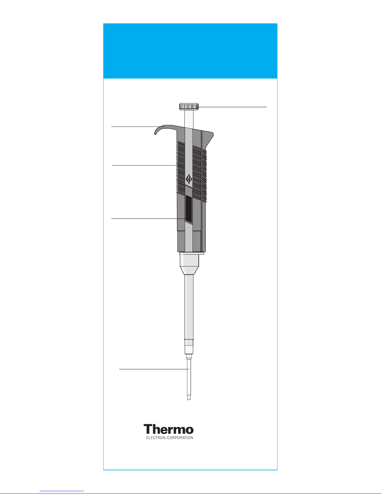
GRIPPY
HANDLE
DIGITAL
DISPLAY
FINNTIP PDP
OPERATING
BUTTON
FINNPIPETTE PDP
INSTRUCTIONS FOR USE
Thermo Electron Oy
P.O.Box 100, Fin-01621 Vantaa, Finland
Tel. +358-9-329 100, fax -358-9-3291 0414
www.thermo.com/finnpipette
Page 2

2
PRODUCT DESCRIPTION
The FINNPIPETTE PDP is a continuously adjustable,
positive displacement pipette specially designed for PCR
(Polymerase Chain Reaction) [1] work.
It operates on the positive displacement principle (i.e. no
air interface) and uses detachable, disposable tips with a
pre-assembled plunger.
FINNPIPETTE PDP pipettes cover a volume range of 0.5 µl
to 200 µl.
RAW MATERIALS
The FINNPIPETTE PDP is made of mechanically durable and
chemically resistant materials:
Operating button PA
Handle polyamide
Tip ejector polyamide
Tip cone PVDF
THE DIGITAL DISPLAY (Fig.1)
The adjusted delivery volume is clearly indicated by the
digital display on the pipette handle.
[1] The Polymerase Chain Reaction process PCR, is
covered by US patents issued to the Cetus Corporation.
DESCRIPTION OF FINNTIP PDP (Fig.4)
FINNPIPETTE PDP tips are supplied in racks of 96 or bags
of 960. The product code numbers are as follows:
Cat.No. Volume Qty
9403070 0.5-25µl 960/bag
9403080 20-200µl 960/bag
PIPETTE OPERATION
SETTING THE DELIVERY VOLUME (Fig.2)
A) The delivery volume is set using the operating button
on the top of the pipette. To increase the delivery
volume turn the operating button counterclockwise. To
decrease, turn it clockwise.
B) Make sure that the desired delivery volume clicks into
place and that the digits are completely visible on the
handle display.
C) Do not set volumes outside of the pipette´s specified
volume range!
ATTACHING A TIP (Fig.5)
Attach a Finntip PDP from a rack as follows:
1. Push the pipette firmly onto the tip until the tip and cone
snap.
2. Without removing the tip from the tray press the
operating button to the first stop to engage the plunger.
3. The tip and plunger are now attached for pipetting.
Page 3

3
TIP EJECTION (Fig.3)
1. To remove the tip and plunger from the pipette simply
press the operating button all the way down.
2. Then release the operating button.
3. This action simutaneously ejects the tip and the
plunger.
PIPETTING TECHNIQUE
Figure 6
A = Ready Position
B = Pipetting Stop
C = Tip Ejection
Ensure that clean tips are firmly pushed on to the tip cones
of the pipette.
The operation of the pipette is controlled by the operating
button. For the best possible accuracy:
Operate the button slowly and with steady speed at all
times, particularly when working with liquids having high
viscosity. Never let the operating button snap back. When
working with serum or biological fluids prime the tips with
the liquid before pipetting. This is done by filling and
emptying the tips.
Hold the pipette vertically (10 degrees maximum from
vertical) during the liquid intake. For maximum hand
control, hold the pipette tightly in the hand with the
"Grippy" resting on the index finger.
Fill a clean reagent reservoir with the liquid to be
dispensed.
1. Depress the operating button to the pipetting stop.
2. Dip the tip just under the surface of the liquid in the
reservoir (2-3 mm) and slowly release the operating
button. Withdraw the tip from the liquid touching them
against the edge the reservoir to remove excess liquid.
3. Deliver the liquid by gently depressing the operating
button to the pipetting stop.
4. Release the operating button to the ready position.
If necessary, change the tips and continue with the
pipetting.
Page 4

4
MAINTENANCE
When the FINNPIPETTE PDP is not in use make sure it is
safely stored in a vertical position, preferably on a
Finnpipette Stand.
SHORT TERM CHECKING
The pipette should be checked at the beginning of each
day for dust and dirt on outside surfaces of the pipette.
Particular attention should be paid to the tip cones.
Solvents should not be used for cleaning the pipette.
LONG TERM MAINTENANCE
If the pipette is used daily it should be checked at least
twice a year. The servicing procedure starts with
disassembly of the pipette.
1. To remove tip cone cover:
Insert the tooth of the service tool into the opening at
the base of the tip cone cover.
2. Pull away the tip cone cover
3. Remove the tip cone by turning it counterclockwise
with the service tool.
4. Pull out the piston.
5. Clean the piston and the piston spring with a dry
napless cloth.
6. Grease the cleaned parts with lubricant provided in
the package.
7. Reassemble the parts.
CALIBRATION
All Finnpipettes are factory calibrated and adjusted to
give the volumes as specified with distilled or deionized
water. Normally, the pipettes do not need adjustment,
but they are constructed to permit recalibration and
adjustment for liquids of different temperature and
viscosity.
DEVICE REQUIREMENTS AND TEST CONDITIONS
An analytical balance must be used. The scale graduation
value of the balance should be chosen according to the
selected test volume of the pipette:
Volume range readable graduation
under 10µl 0.001mg
10-100µl 0.01mg
above 100µl 0.1mg
Page 5

5
Test liquid: Water, distilled or deionized, “grade 3” water
conforming ISO 3696. Tests are done in a draft-free room
at a constant (±0.5°C) temperature of water, pipette and
air between 20°C to 25°C. The relative humidity must be
above 55%. Especially with volumes under 50 µl the air
humidity should be as high as possible to reduce the
effect of evaporation loss. Special accessories, such as
the evaporation trap, are recommended.
CHECKING THE CALIBRATION
A new tip is first pre-wetted 3-5 times and a series of ten
pipettings are done with both volumes.
A pipette is always adjusted for delivery (Ex) of the
selected volume. Measuring volumes taken from balance
is not allowed. If the calculated results are in the limits, the
calibration of the pipette is correct.
Procedure:
1. Do 10 pipettings with the lower volume.
2. Do 10 pipettings with the maximum volume.
3. Calculate the accuracy (A) and precision (cv) of both
series.
4. Compare the results to the limits in the Table 1.
If the results are in the limits of Table 1, then the calibration
of the pipette is correct. Otherwise the pipette must be
adjusted and checked again.
Range Volume Accuracy Precision
µl µl % s.d. µl cv%**
0,5-25 µl 25 µl ±0.625 ±2.5 0.250 1.0
5 µl ±0.250 ±5.0 0.125 2.5
0.5 µl * * * *
20-200 µl 200 µl ±3.0 ±1.5 0.40 0.2
50 µl ±2.0 ±4.0 0.25 0.5
20 µl * * * *
*User dependent **s.d. = Standard Deviation, CV =
Coefficient of Variation
ADJUSTMENT (Fig.7)
Adjustment is done with the service tool.
1. Place the service tool into the openings of the
calibration nut at the top of the handle.
2. Turn the service tool clockwise to decrease, or
counterclockwise to increase the volume.
3. After adjustment check the calibration according to the
instructions above.
Page 6

6
FORMULAS FOR CALCULATING RESULTS
Conversion of mass to volume
V = (w + e) x Z
V = volume (µl)
w = weight (mg)
e = evaporation loss (mg)
Z = conversion factor for mg/µl conversion
Evaporation loss can be significant with low volumes. To
determine mass loss, dispense water to the weighing
vessel, note the reading and start a stopwatch.
See how much the reading decreases during 30 seconds
(e.g. 6 mg = 0.2 mg/s). Compare this to the pipetting time
from tareing to reading. Typically pipetting time might be 10
seconds and the mass loss is 2 mg (10s x 0.2mg/s) in this
example. If an evaporation trap or lid on the vessel is used
the correction of evaporation is usually unnecessary.
The factor Z is for converting the weight of the water to
volume at test temperature and pressure. A typical value
is 1.0032 µl/mg at 22°C and 95 kPa. See the conversion
table on page 8.
Accuracy (systematic error)
Accuracy is the difference between the dispensed
volume and the selected volume of a pipette.
A = V - V
0
A = accuracy
V = mean volume
V0= nominal volume
Accuracy can be expressed as a relative value:
A% = 100% x A / V
0
Precision (random error)
Precision refers to the repeatability of the pipettings. It is
expressed as standard deviation (s) or coefficient of
variation (cv)
1
)(
2
-
-
=
n
VV
S
i
S
i=1
n
PACKAGE
The FINNPIPETTE PDP is shipped in a specially designed
package containing the following items:
1. The pipette
2. Instruction manual
3. Service tool
4. Calibration certificate
5. Sample of Finntip PDP
s = standards deviation
v = mean volume
n = number of measurements
cv is the relative value of standard
deviation.
cv = 100% x s / v
Page 7

7
TROUBLE SHOOTING
The following table is a guide to possible problems and
their solutions.
Fault
Leakage
Inaccurate
dispensing
Inaccurate
dispensing
with certain
liquids
Possible reason
Tip incorrectly
attached
Foreign bodies
between tips and
tip cones
Incorrect operation
Tips incorrectly
attached
Calibration altered:
e.g. caused by
misuse
Unsuitable
calibration. Many
high viscosity
liquids require
recalibration
Solution
Attach firmly
Clean tip cones
thoroughly and
attach new tips
Follow instructions
carefully
Attach firmly
Recalibrate
according to
instructions
Recalibrate with the
liquids in question
CAUTION!
The Finnpipette is designed to allow easy in-lab service.
If you, however, want to send the pipette to us or to our
local representative for service, please, enclose a list of
any infectious, radioactive or otherwise hazardous
materials that have been pipetted.
Also, please, note that the postal authorities in your
country may limit the sending of contaminated material
by mail.
Page 8

8
Temper- Air pressure
ature °C hPA (mbar)
800 853 907 960 1013 1067
15 1.0018 1.0018 1.0019 1.0019 1.0020 1.0020
15.5 1.0018 1.0018 1.0019 1.0020 1.0020 1.0021
16 1.0019 1.0020 1.0020 1.0021 1.0021 1.0022
16.5 1.0020 1.0020 1.0021 1.0022 1.0022 1.0023
17 1.0021 1.0021 1.0022 1.0022 1.0023 1.0023
17.5 1.0022 1.0022 1.0023 1.0023 1.0024 1.0024
18 1.0022 1.0023 1.0024 1.0024 1.0025 1.0025
18.5 1.0023 1.0024 1.0025 1.0025 1.0026 1.0026
19 1.0024 1.0025 1.0025 1.0026 1.0027 1.0027
19.5 1.0025 1.0026 1.0026 1.0027 1.0028 1.0028
20 1.0026 1.0027 1.0027 1.0028 1.0029 1.0029
20.5 1.0027 1.0028 1.0028 1.0029 1.0030 1.0030
21 1.0028 1.0029 1.0030 1.0030 1.0031 1.0031
21.5 1.0030 1.0030 1.0031 1.0031 1.0032 1.0032
22 1.0031 1.0031 1.0032 1.0032 1.0033 1.0033
22.5 1.0032 1.0032 1.0033 1.0033 1.0034 1.0035
23 1.0033 1.0033 1.0034 1.0035 1.0035 1.0036
23.5 1.0034 1.0035 1.0035 1.0036 1.0036 1.0037
24 1.0035 1.0036 1.0036 1.0037 1.0038 1.0038
24.5 1.0037 1.0037 1.0038 1.0038 1.0039 1.0039
25 1.0038 1.0038 1.0039 1.0039 1.0040 1.0041
25.5 1.0039 1.0040 1.0040 1.0041 1.0041 1.0042
26 1.0040 1.0041 1.0042 1.0042 1.0043 1.0043
26.5 1.0042 1.0042 1.0043 1.0043 1.0044 1.0045
27 1.0043 1.0044 1.0044 1.0045 1.0045 1.0046
27.5 1.0044 1.0045 1.0046 1.0046 1.0047 1.0047
28 1.0046 1.0046 1.0047 1.0048 1.0048 1.0049
28.5 1.0047 1.0048 1.0048 1.0049 1.0050 1.0050
29 1.0049 1.0049 1.0050 1.0050 1.0051 1.0052
29.5 1.0050 1.0051 1.0051 1.0052 1.0052 1.0053
30 1.0052 1.0052 1.0053 1.0053 1.0054 1.0055
CONVERSION TABLE
Value of the conversion factor Z (µl/mg), as a function of
temperature and pressure, for distilled water.
2
1
1 5 . 0
La
Page 9

9
2 5 .0
Labsystems
1 2
3
3
2 5 .0
Labsystems
5
25 µl 200 µl
4
Page 10

10
absystems
6
A
C
B
1 2
3 4
7
Pipetting
Tip Ejection
Page 11

11
No. Item Product Codes
25 µl 200 µl
1. Service Tool 10589070 10589070
2. Cap 1057490 1057500
3. Handle Back 10588030 10588030
4. Limiter 1092990 1092990
5. Handle 2204030 2204040
6. Locking Pieces 1058180 1058180
7. Plunger 1106230 1106300
8. Oper. Spring 1130720 1130720
9. Ring 1006500
10. Tip Cone 1058790 10588000
11. Tip Cone Cover 10588011 10588011
SPARE PARTS
1
2
4
5
3
6
7
8
9
10
11
Page 12

12
1504760-06
Product specifications are subject to change without
prior notice. Finpipette
®
and Finntip® are registered
trademarks of Thermo Electron Oy.
Thermo Electron Oy
P.O.Box 100, Fin-01621 Vantaa, Finland
Tel. +358-9-329 100, fax -358-9-3291 0414
www.thermo.com/finnpipette
 Loading...