

Page 1

1
Finnpipette® F1
Single Channel
Variable & Fixed Volume
Multichannel
Instructions for Use
Bedienungsanleitung
Guide d´utilisation
Instrucciones de uso
取扱説明書
User Manual
Page 2

2
This product complies with the European Union Directive 98/79/EC, and it is marked with
a CE-marking.
When the product is used in applications related to the directive 98/79/EC, read the
additional information at www.thermofi sher.com or contact the manufacturer at info.
pipettes@thermofi sher.com to ensure correct and safe use.
The CE-mark covers the system containing the CE-marked Finnpipette F1 pipette and the
CE-marked Finntips.
Product specifi cations are subject to change without prior notice. Finnpipette® and Finntip®
are registered trademarks of Thermo Fisher Scientifi c Oy.
Ce produit est conforme à la directive de l’Union européenne 98/79/CE et porte le
marquage CE.
Lorsque le produit est utilisé pour des applications relatives à la directive 98/79/EC, veuillez
prendre connaissance des informations complémentaires à www.thermofi sher.com ou
contacter le constructeur à info.pipettes@thermofi sher.com. Ceci pour garantir un usage
adéquat et sûr.
Le marquage CE s’applique au système comprenant la Finnpipette F1 et les cônes Finntip.
Les spécifi cations du produit sont sujettes à modifi cation sans avis préalable. Finnpipette
®
et Finntip® sont des marques déposées de Thermo Fisher Scientifi c Oy.
Este producto cumple la Directiva de la Unión Europea 98/79/CE y presenta el marcado CE.
Cuando el producto sea usado en aplicaciones afectadas por la directiva 98/79/EC, por favor,
lea la información adicional en www.thermofi sher.com o contacte con el fabricante en
info.pipettes@thermofi sher.com para asegurar su uso correcto y seguro.
El marcado CE corresponde al sistema que contiene la pipeta Finnpipette F1 con el marcado
CE y las puntas de pipeta Finntip con marcado CE.
Las especifi caciones del producto pueden cambiar sin previo aviso. Finnpipette
®
y Finntip
®
son marcas registradas de Thermo Fisher Scientifi c Oy.
本製品は欧州指令98/79/ECに準拠しており、CEマーキングが付いています。
製品を指令98/79/ECに関連するアプリケーションで使用するときは、適切で安全に
ご使用いただくため、
www.thermofi sher.com に掲載の追加情報をお読みになる
か、製造元info.pipettes@thermofisher.com にお問い合わせください。
CEマークは、CEマークの付いた
Finnpipette F1ピペットおよびCEマークの付いた
Finntipピペットチップを含むシステムを対象としています。
製品仕様は事前の予告なく変更されることがあります。フィンピペット
®
とフィンチ
ップ
®
は、サーモフィッシャーサイエンティフィックの登録商標です。
Dieses Produkt entspricht der Europäischen Richtlinie 98/79/EG und ist mit dem CE-Symbol
gekennzeichnet.
Sollte das Produkt in Anwendungen verwendet werden, die in Verbindung zur Direktive
98/79/EC stehen, lesen Sie die Zusatzinformationen auf www.thermofi sher.com oder
kontaktieren Sie den Hersteller unter info.pipettes@thermofi sher.com, um die richtige
und sichere Verwendung zu gewährleisten.
Die CE-Kennzeichnung bezieht sich auf die Kombination der Finnpipette F1 mit FinntipPipettenspitzen.
Wir behalten uns das Recht auf unangekündigte Änderungen der Produktspezifi kationen vor.
Finnpipette® und Finntip® sind eingetragene Warenzeichen der Fa. Thermo Fisher Scientifi c Oy.
Page 3

3
CONTENTS
PRODUCT DESCRIPTION 4
PACKAGE 5
SAFETY 5
PIPETTE OPERATION 6
PIPETTING TECHNIQUES 7
CALIBRATION AND ADJUSTMENT 8
MAINTENANCE 12
TROUBLE SHOOTING 14
SPARE PARTS 63-71
English
INHALT
PRODUKTBESCHREIBUNG 15
PACKUNGSINHALT 16
SICHERHEIT 16
BEDIENUNG DER PIPETTE 17
PIPETTIERMETHODEN 18
KALIBRIERUNG UND JUSTIERUNG 19
WARTUNG 23
FEHLERBEHEBUNG 26
ERSATZTEILE UND ZUBEHÖR 63-71
Deutsch
SOMMAIRE
DESCRIPTION DU PRODUIT 27
CONDITIONNEMENT 28
CONSIGNES DE SÉCURITÉ 28
UTILISATION DE LA PIPETTE 29
MÉTHODES DE PIPETAGE 30
CALIBRAGE 31
ENTRETIEN 35
EN CAS DE PROBLEME 37
PIÈCES DÉTACHÉES 63-71
Français
CONTENIDO
DESCRIPCIÓN DEL PRODUCTO 38
PAQUETE 38
SEGURIDAD 38
USO DE LA PIPETA 40
TÉCNICAS DE PIPETEO 41
CALIBRACIÓN Y AJUSTE 42
MANTENIMIENTO 46
SOLUCIÓN DE PROBLEMAS 49
PIEZAS DE RECAMBIO 63-71
Español
目次
製品について 50
パッケージ 51
安全にお使いいただくために 51
ピペットの操作 52
ピペッティングテクニック 53
キャリブレーション 54
メンテナンス 58
トラブルシューティング 60
保証規定 62
パーツ及び付属品 63-71
日
本
語
Page 4

4
Product description
The Finnpipette F1 is a continuously adjustable, general purpose micropipette for sampling and
dispensing accurate liquid volumes.
It operates on an air displacement principle (i.e. an air interface) and uses detachable, disposable tips.
The adjusted delivery volume is displayed digitally on a readout window in the handle.
The fourteen different models of Finnpipette F1 pipettes cover a volume range from 0,2 μl to 10 ml.
Order No. Volume Range
Color code
Finntip
4641010N 0,2 μl to 2 μl pink Flex 10, 10, 20, 50
4641020N 0,5 μl to 5 μl pink Flex 10, 10, 20, 50
4641030N 1 μl to 10 μl pink Flex 10, 10, 20, 50
4641040N 1 μl to 10 μl yellow
Flex 200, 250 Univ., 200 Ext, 300, Flex 300
4641050N 2 μl to 20 μl
turquoise
50
4641060N 2 μl to 20 μl yellow
Flex 200, 250 Univ., 200 Ext, 300, Flex 300
4641130N 5 μl to 50 μl
turquoise
50
4641140N 5 μl to 50 μl yellow
Flex 200, 250 Univ., 200 Ext, 300, Flex 300
4641070N 10 μl to 100 μl yellow
Flex 200, 250 Univ., 200 Ext, 300, Flex 300
4641080N 20 μl to 200 μl yellow
Flex 200, 250 Univ., 200 Ext, 300, Flex 300
4641090N 30 μl to 300 μl orange Flex 300, 300
4641100N 100 μl to 1000 μl blue Flex 1000, 1000, 1000 Ext
4641110N 0,5 ml to 5 ml green 5 ml
4641120N 1 ml to 10 ml red 10 ml, Flex 10 ml Ext
The thirteen different models of Finnpipette F1 Fixed Volume pipettes cover a volume range
from 1 μl to 10 ml.
Order No. Volume Range Color code Finntip
4651020N 10 μl dark blue Flex 200, 250 Univ., 200 Ext, 300, Flex 300
4651130N 20 μl dark blue Flex 200, 250 Univ., 200 Ext, 300, Flex 300
4651030N 25 μl dark blue Flex 200, 250 Univ., 200 Ext, 300, Flex 300
4651040N 50 μl dark blue Flex 200, 250 Univ., 200 Ext, 300, Flex 300
4651050N 100 μl dark blue Flex 200, 250 Univ., 200 Ext, 300, Flex 300
4651140N 200 μl dark blue Flex 200, 250 Univ., 200 Ext, 300, Flex 300
4651060N 250 μl dark blue Flex 1000, 1000, 1000 Ext
4651070N 500 μl dark blue Flex 1000, 1000, 1000 Ext
4651080N 1000 μl dark blue Flex 1000, 1000, 1000 Ext
4651090N 2000 μl dark blue 5 ml
4651100N 3000 μl dark blue 5 ml
4651110N 5000 μl dark blue 5 ml
4651120N 10000 μl dark blue 10 ml, Flex 10 ml Ext
The ten different models of Finnpipette F1 Multichannel pipettes cover a volume range from
1 μl to 300 μl.
Order No. Channel Volume Range Color code Finntip
4661000N 8 1 μl to 10 μl pink Flex 10, 10, 20, 50
4661010N 8 5 μl to 50 μl yellow
Flex 200, 250 Univ., 200 Ext, 300, Flex 300
4661020N 8 10 μl to 100 μl yellow
Flex 200, 250 Univ., 200 Ext, 300, Flex 300
4661030N 8 30 μl to 300 μl orange Flex 300, 300
4661040N 12 1 μl to 10 μl pink Flex 10, 10, 20, 50
4661050N 12 5 μl to 50 μl yellow
Flex 200, 250 Univ., 200 Ext, 300, Flex 300
4661060N 12 10 μl to 100 μl yellow
Flex 200, 250 Univ., 200 Ext, 300, Flex 300
4661070N 12 30 μl to 300 μl orange Flex 300, 300
4661080N 16 1 μl to 10 μl purple 20
4661090N 16 5 μl to 50 μl
turquoise
50
English
Page 5
5
English
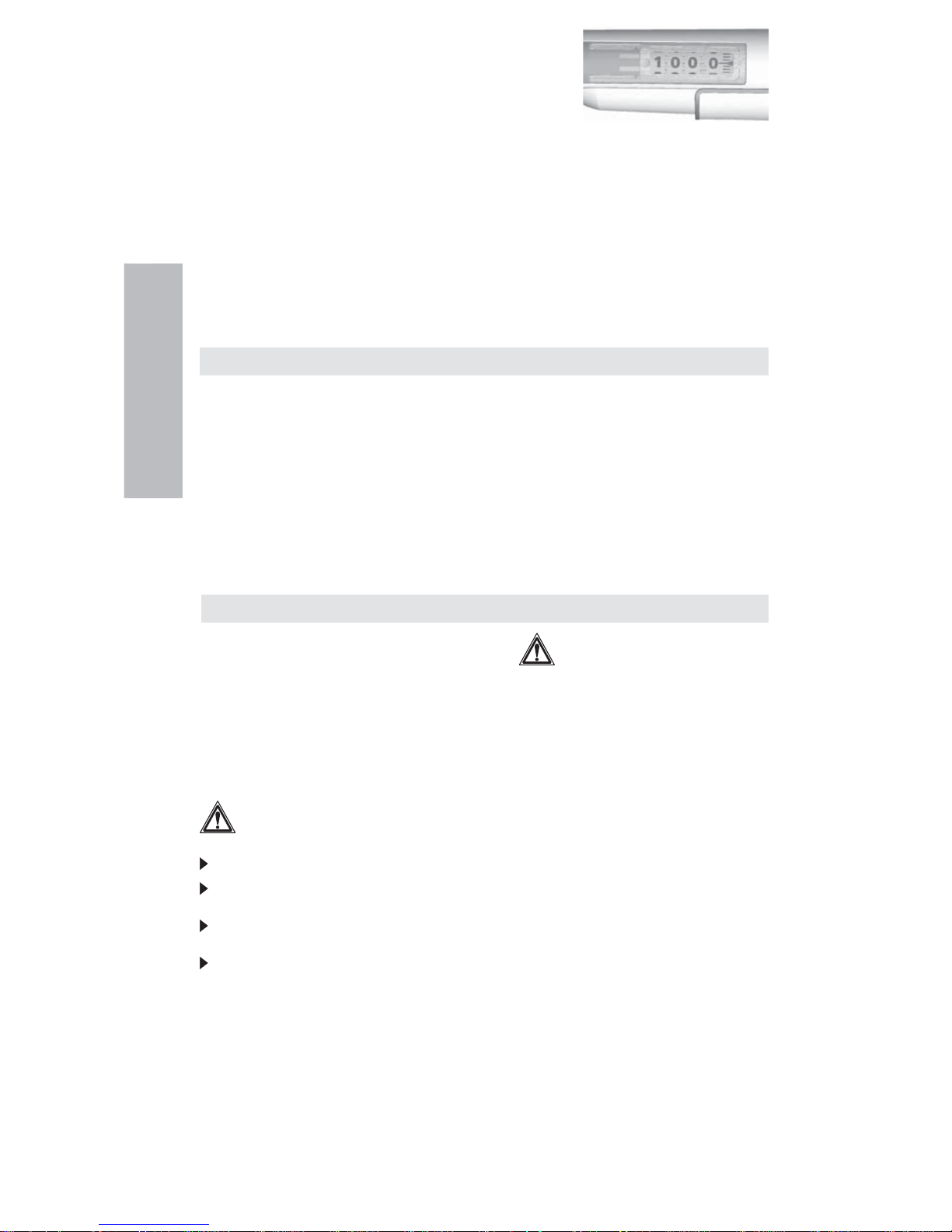
Digital display
The adjusted delivery volume is clearly indicated in the large
digital display on the handle.
Raw materials
The Finnpipette F1 is made of mechanically durable and chemically resistant materials.
For waste disposal instructions, please contact your local environmental agency. For more
information, please contact us at info.pipettes@thermofi sher.com.
Description of tips
Finntips are recommended for use with the Finnpipette F1.
They are made of virgin natural colour polypropylene, generally regarded as the only
contamination free material suitable for tips. Finntips are also autoclavable (121°C).
Package
The Finnpipette F1 is shipped in a specially designed package containing the following items:
1. The Finnpipette
2. Service tool
3. Multichannel service tool
4. Finntip sample
5. Tube of grease (Order No. 2203130)
6. Instruction manual
7. Calibration certifi cate / Warranty certifi cate
8. Shelf hanger (Order No. 2206040)
9. Two stickers
Safety
Cautions are marked with this symbol .
Intended use
The intended use of the device is to transfer liquids in the volume range of
0,2 μl to 10 ml.
The F1 Finnpipette pipette and Finntips are designed as a component of an analyzing system
for an end user, who is responsible for validating the system to ensure reliable and safe results.
Damage to health
Follow general procedures for hazard prevention and safety instructions; e.g. wear
protective clothing, eye protection and gloves.
For use and waste disposal of hazardous (e.g. radioactive and potentially infectious)
material, follow the safety instructions and general laboratory practice.
The pipette and tips are not intended for in vivo use. Do not use the pipette for pipetting any
liquid to be injected into a human body.
Do not eject the tip towards anybody.
The Finnpipette F1 is to be used by trained personnel with required laboratory skills. The
instructions for use must be read prior to and during the use of the device (pipette and tip). The
F1 pipette can be used between +4°C and +40°C.
Incorrect dispensing results
Performance may vary due to:
a. pipetting method (forward pipetting technique recommended)
b. temperature (air, liquid, vessel, pipette, and tip)
c. pressure
d. humidity
e. operator, e.g. thumb movement, pipetting angle
f. liquid density, viscosity and vapor pressure
g. type of tip
Page 6
6
If the pipetting performance is critical to the outcome of a specifi c application, the result has
to be assured with an alternative test, and if this is not an option, by duplicate testing.
The possibility of an incorrect volume delivery during pipetting cannot be entirely mitigated.
To avoid inaccurate dispensing and/or leakage, check that the tip is properly attached to
the pipette.
When rotating the volume adjustment button, do not exceed the volume range of the pipette.
Otherwise the pipette may be damaged or affect pipetting performance.
Pipetting performance cannot be guaranteed if the tip is reused.
Choose only a tip and pipette with matching color coding.
Disposal of the Materials
Follow laboratory and country-specifi c procedures for the disposal of biohazardous or radioactive
waste. Refer to local regulations for the disposal of infectious material.
Warning The tips can be potentially infectious. Dispose of all used disposable tips as
biohazardous waste.
Warning Decontaminate the pipette before disposal.
For waste disposal instructions, contact your local environmental agency. For more information,
please contact us at info.pipettes@thermofi sher.com
Regarding the original packaging and packing materials, use the recycling operators known
to you.
For more information, contact your local Thermo Fisher Scientifi c representative.
Pipette operation
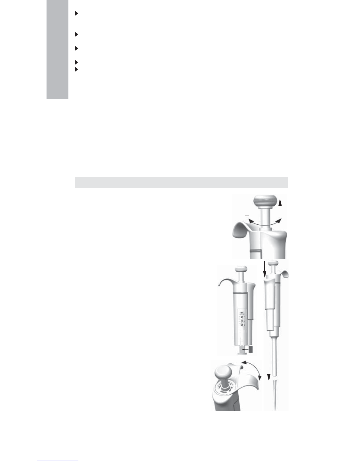
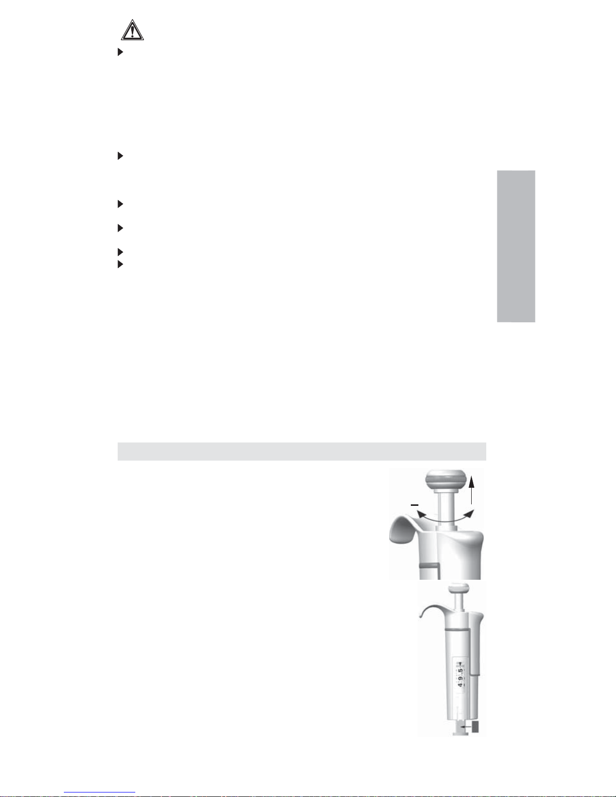
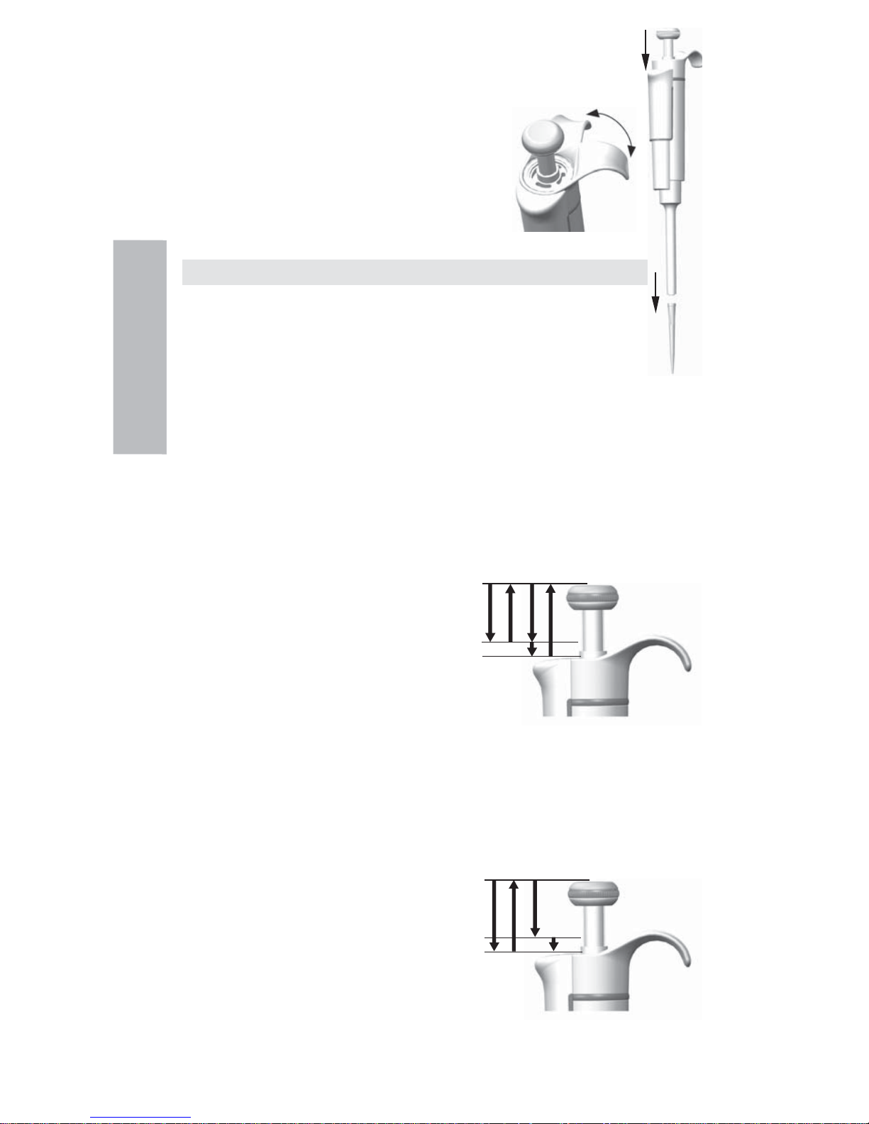
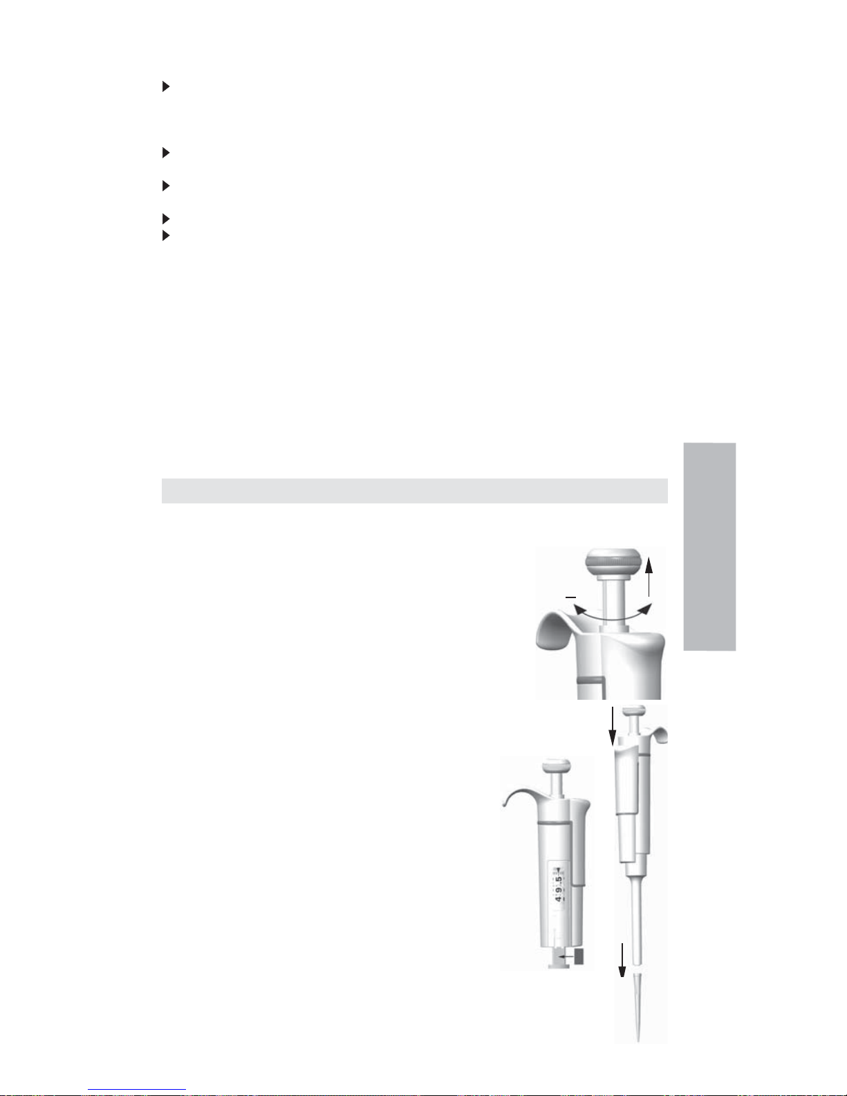
Setting the delivery volume
1. Set the delivery volume using the knob on the top of the pipette.
Pull the knob to activate the volume setting.
2. To increase the delivery volume, turn the knob
counterclockwise. To decrease the delivery volume,
turn it clockwise.
3. Make sure that the desired delivery volume clicks into place.
4. Do not set volumes outside the pipette´s specifi ed volume range.
Using excessive force to turn the knob outside the range may
jam the mechanism and eventually damage the pipette.
5. Lock the volume by pushing the knob down.
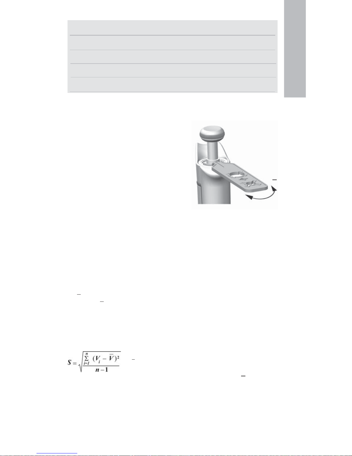
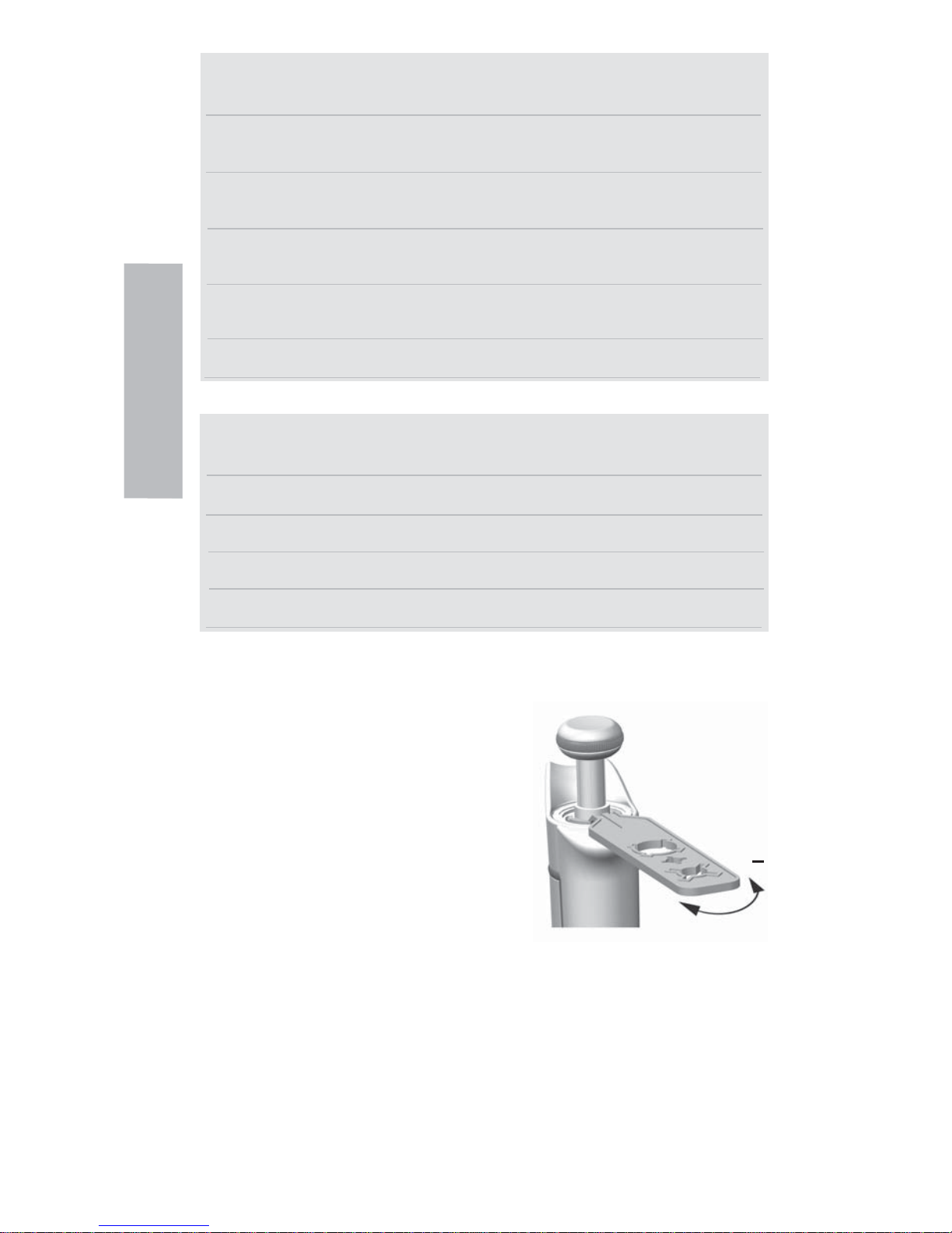
ID-tag
You can mark the pipette application, your initials, the
calibration date, etc. on the ID-tag. Remove the pipette’s
module to replace the tag. Mark the label with a pencil and
slide the tag together with the holder back to it’s slot.
Tip ejection
To help eliminate the risk of contamination, each pipette is
fi tted with a tip ejector system. To release the tip, point the
pipette at suitable waste receptacle and press the tip ejector
with your thumb.
Adjusting the fi nger rest
The fi nger rest can be adjusted by rotating it 60 degrees
to both directions of the center position. Usually right
handed operators turn it left (counter clockwise) to get the
best possible position for the thumb to eject the tip. See
picture.
English
+
1
2
Page 7

7
Pipetting techniques
Push and release the knob slowly at all times particularly when working with high viscosity
liquids. Never allow the knob to snap back.
Make sure that the tip is fi rmly attached to the tip cone. Check for foreign particles in the tip.
Before you begin your actual pipetting work, fi ll and empty the tip 2-3 times with the solution
that you will be pipetting. Hold the pipette in an upright position while aspirating liquid. The
fi nger rest should rest on your index fi nger. Make sure that the tips, pipette and solution are at
the same temperature.
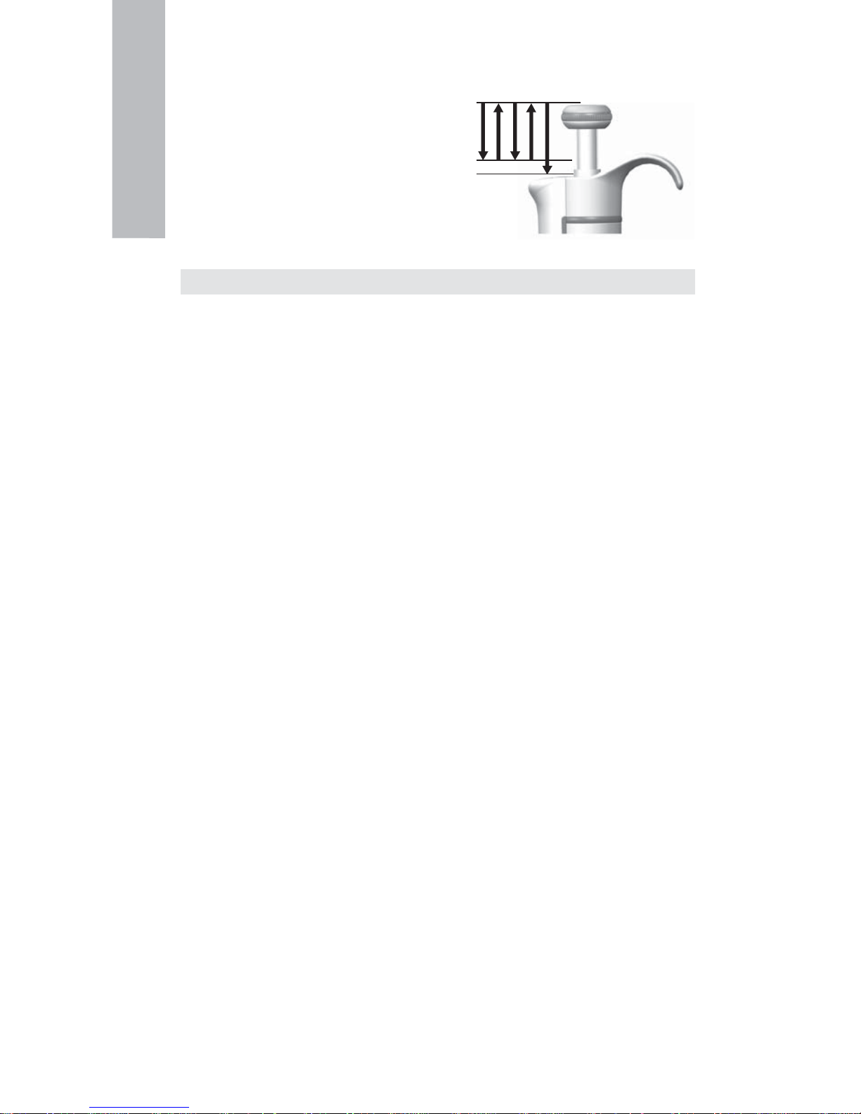
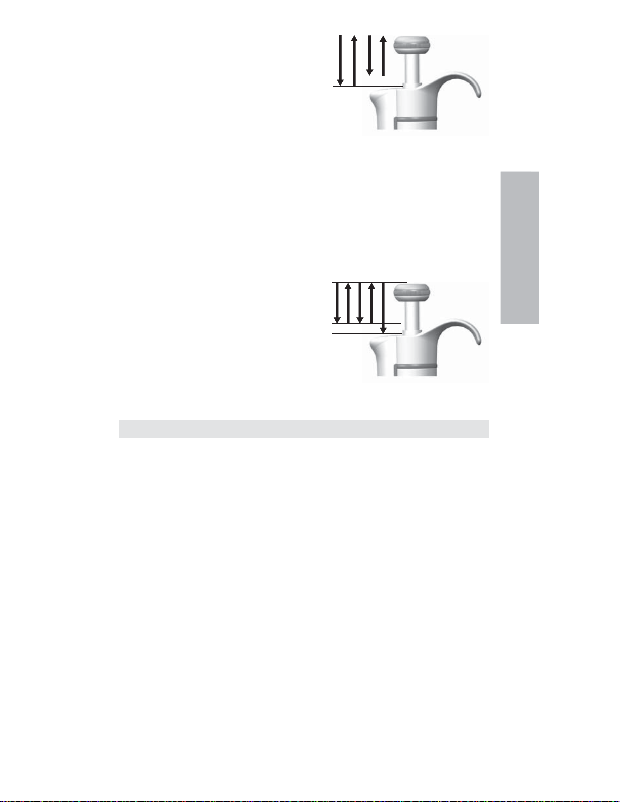
Forward technique
Fill a clean reagent reservoir with the liquid to be dispensed.
1 Depress the knob to the fi rst stop.
2. Dip the tip under the surface of the liquid in the
reservoir to a depth of about 1 cm and slowly
release the knob. Withdraw the tip from the
liquid touching it against the edge of the reservoir
to remove excess liquid.
3. Deliver the liquid by gently depressing the knob
to the fi rst stop. After a delay of about one
second, continue to depress the knob all the way
to the second stop. This action will empty the tip.
4. Release the knob to the ready position. If necessary, change the tip and continue pipetting.
Reverse technique
The reverse technique is suitable for dispensing liquids that have a high viscosity or a tendency
to foam easily. The technique is also recommended for dispensing very small volumes. Fill a
clean reagent reservoir with the liquid to be dispensed.
1. Depress the knob all the way to the second stop.
2. Dip the tip under the surface of the liquid in the
reservoir to a depth of about 1 cm, and slowly
release the knob. This action will fi ll the tip.
Withdraw the tip from the liquid touching it
against the edge of the reservoir to remove
excess liquid.
3. Deliver the preset volume by gently depressing
the knob to the fi rst stop. Hold the knob at the fi rst
stop. Some liquid will remain in the tip and this should not be included in the delivery.
4. The remaining liquid should either be discarded with the tip or pipetted back into
the container.
Repetitive technique
The repetitive technique offers a rapid and simple procedure for repeated delivery of the same
volume. Fill a clean reagent reservoir with the liquid to be dispensed.
1. Depress the knob all the way to the second stop.
2. Dip the tip under the surface of the liquid in the
reservoir to a depth of about 1 cm, and slowly re
lease the knob. This action will fi ll the tip.
Withdraw the tipfrom the liquid touching against
the edge of the reservoir to remove excess liquid.
3. Deliver the preset volume by gently depressing
the knob to the fi rst stop. Hold the knob at the
fi rst stop. Some liquid will remain in the tip and
this should not be included in the delivery.
4. Continue pipetting by repeating steps 3 and 4.
English
1 2 3 4
1 2 3 4
1 2 3 4
Page 8
8
Pipetting of heterogeneous samples
(deproteinization in blood glucose determination, for example)
Use steps 1 and 2 of the forward technique to fi ll the tip with blood.
Wipe the tip carefully with a dry clean tissue.
1. Immerse the tip into the reagent and depress the
knob to the fi rst stop, making sure the tip is well
below the surface.
2. Release the knob slowly to the ready position.
This will fi ll the tip. Keep the tip in the solution.
3. Depress the knob to the fi rst stop and release
slowly. Keep repeating this procedure until the
interior wall of the tip is clear.
4. Finally, depress the knob all the way to the
second stop to completely empty the tip.
Calibration and adjustment
All Finnpipettes are factory calibrated and adjusted to give the volumes as specifi ed with
distilled or deionized water using the forward pipetting technique. It should be noted that the
use of other pipetting techniques may affect the calibration results. The pipettes are constructed
to permit re-adjustment for other pipetting techniques or liquids of different temperature and
viscosity.
Device requirements and test conditions
An analytical balance must be used. The scale graduation value of the balance should be chosen
according to the selected test volume of the pipette:
Volume range readable graduation
under 10 μl 0.00 1 mg
10-100 μl 0.01 mg
above 100 μl 0.1 mg
Test liquid: Water, distilled or deionized, “grade 3” water conforming ISO 3696. Tests are done
in a draft-free room at a constant (±0.5°C) temperature of water, pipette and air between 15°C
to 30°C. The relative humidity must be above 50%. Especially with volumes under 50 μl the
air humidity should be as high as possible to reduce the effect of evaporation loss. Special
accessories, such as the evaporation trap, are recommended.
Procedure to check calibration
The pipette is checked with the maximum volume (nominal volume) and with the minimum
volume. A new tip is fi rst pre-wetted 3-5 times and a series of ten pipettings is done with
both volumes. A pipette is always adjusted for delivery (Ex) of the selected volume. Use of
forward pipetting technique is recommended. The maximum permissible errors are designed for
forward method. It is recommended to calibrate all channels of the multichannel pipette, but a
suitable method is also to calibrate only the edge channels. Adjustment check prior calibration is
done using one of the middle channels. It is recommended to use the ISO8655 calibration limits
presented in the following tables or user-defi ned specifi cations.
Procedure:
1. Do 10 pipettings with the minimum volume.
2. Do 10 pipettings with the maximum volume.
3. Calculate the inaccuracy (A) and imprecision (cv) of both series.
4. Compare the results to the limits.
If the calculated results are within the selected limits, the adjustment of the pipette is correct.
English
1 2 3 4 5
Page 9

9
ISO8655 calibration specifi cations
Thermo Scientifi c Finnpipette F1 specifi cations according to ISO8655 standard.
Finnpipette F1 Variable Volume Single Channel
Range Volume Inaccuracy Imprecision
μl μl % s.d. μl cv%
0,2-2 μl 2 ±0.080 ±4 0.040 2.0
0.2 ±0.080 ±40 0.040 20.0
0,5-5 μl 5 ±0.125 ±2.5 0.075 1.5
0.5 ±0.125 ±25 0.075 15
1-10 μl 10 ±0.120 ±1.2 0.080 0.8
1 ±0.120 ±12 0.080 8.0
2-20 μl 20 ±0.20 ±1.0 0.10 0.5
2 ±0.20 ±10.0 0.10 5.0
5-50 μl 50 ±0.50 ±1.0 0.20 0.4
5 ±0.50 ±10 0.20 4.0
10-100 μl 100 ±0.80 ±0.8 0.30 0.3
10 ±0.80 ±8.0 0.30 3.0
20-200 μl 200 ±1.60 ±0.8 0.60 0.3
20 ±1.60 ±8.0 0.60 3.0
30-300 μl 300 ±4.0 ±1.3 1.5 0.5
30 ±4.0 ±13 1.5 5.0
100-1000 μl 1000 ±8.0 ±0.8 3.0 0.3
100 ±8.0 ±8.0 3.0 3.0
0,5-5 ml 5000 ±40.0 ±0.8 15.0 0.3
500 ±40.0 ±8.0 15.0 3.0
1-10 ml 10000 ±60.0 ±0.6 30.0 0.3
1000 ±60.0 ±6.0 30.0 3.0
Finnpipette F1 Fixed Volume Single Channel
Fixed Volume Inaccuracy Imprecision
μl μl % s.d.μl cv%
10 ±0.120 ±1.20 0.080 0.80
20 ±0.20 ±1.00 0.10 0.50
25 ±0.50 ±2.00 0.20 0.80
50 ±0.50 ±1.00 0.20 0.40
100 ±0.80 ±0.80 0.30 0.30
200 ±1.60 ±0.80 0.60 0.30
250 ±4.00 ±1.60 1.50 0.60
500 ±4.00 ±0.80 1.50 0.30
1000 ±8.00 ±0.80 3.00 0.30
2000 ±16.0 ±0.80 6.00 0.30
3000 ±40.0 ±1.33 15.00 0.50
5000 ±40.0 ±0.80 15.00 0.30
10000 ±60.0 ±0.60 30.00 0.30
Finnpipette F1 Variable Volume Multichannel
Range Channel Volume Inaccuracy Imprecision
μl μl % s.d.μl cv%
1-10 μl 8, 12, 16 10 ±0.24 ±2.4 0.16 1.6
1 ±0.24 ±24 0.16 16
5-50 μl 8, 12, 16 50 ±1.0 ±2.0 0.4 0.8
5 ±1.0 ±20 0.4 8.0
10-100 μl 8, 12 100 ±0.80 ±0.8 0.30 0.3
10 ±0.80 ±8.0 0.30 3.0
30-300 μl 8, 12 300 ±8.0 ±2.7 3.0 1.0
30 ±8.0 ±26.7 3.0 10.0
English
Page 10

10
Manufacturer specifi cation limits
Finnpipette F1 Variable Volume Single Channel
Range Volume Inaccuracy Imprecision Factory
μl μl % s.d. μl cv% calibration tip
0.2-2 μl 2 ±0,050 ±2,50 0,040 2,00 Flex 10
0,2 ±0,024 ±12,00 0,020 10,00
0.5-5 μl 5 ±0,075 ±1,50 0,050 1,00 Flex 10
0,5 ±0,030 ±6,00 0,025 5,00
1-10 μl, micro 10 ±0,100 ±1,00 0,050 0,50 Flex 10
1 ±0,025 ±2,50 0,020 2,00
1-10 μl 10 ±0,100 ±1,00 0,080 0,80 Flex 200
1 ±0,035 ±3,50 0,030 3,00
2-20 μl, micro 20 ±0,20 ±1,00 0,08 0,40 50
2 ±0,06 ±3,00 0,05 2,50
2-20 μl 20 ±0,20 ±1,00 0,08 0,40 Flex 200
2 ±0,06 ±3,00 0,05 2,50
5-50 μl, micro 50 ±0,30 ±0,60 0,15 0,30 50
5 ±0,15 ±3,00 0,125 2,50
5-50 μl 50 ±0,30 ±0,60 0,15 0,30 Flex 200
5 ±0,15 ±3,00 0,125 2,50
10-100 μl 100 ±0,80 ±0,80 0,20 0,20 Flex 200
10 ±0,30 ±3,00 0,10 1,00
20-200 μl 200 ±1,2 ±0,60 0,4 0,20 Flex 200
20 ±0,36 ±1,80 0,14 0,70
30-300 μl 300 ±1,8 ±0,60 0,6 0,20 Flex 300
30 ±0,45 ±1,50 0,18 0,60
100-1000 μl 1000 ±6,0 ±0,60 2,0 0,20 Flex 1000
100 ±1,0 ±1,00 0,6 0,60
0,5-5 ml 5000 ±25,0 ±0,50 10,0 0,20 5 ml
500 ±10,0 ±2,00 4,0 0,80
1-10 ml 10000 ±50,0 ±0,50 20,0 0,20 10 ml
1000 ±20,0 ±2,00 8,0 0,80
Finnpipette F1 Fixed Volume Single Channel
Fixed Volume Inaccuracy Imprecision Factory
μl μl % s.d. μl cv% calibration tip
10 ±0,090 ±0,90 0,080 0,80 Flex 200
20 ±0,14 ±0,70 0,10 0,50 Flex 200
25 ±0,15 ±0,60 0,125 0,50 Flex 200
50 ±0,30 ±0,60 0,20 0,40 Flex 200
100 ±0,40 ±0,40 0,30 0,30 Flex 200
200 ±0,80 ±0,40 0,60 0,30 Flex 200
250 ±1,0 ±0,40 0,75 0,30 Flex 1000
500 ±1,5 ±0,30 1,5 0,30 Flex 1000
1000 ±3,0 ±0,30 3,0 0,30 Flex 1000
2000 ±6,0 ±0,30 4,0 0,20 5 ml
3000 ±9,0 ±0,30 6,0 0,20 5 ml
4000 ±12,0 ±0,30 8,0 0,20 5 ml
5000 ±15,0 ±0,30 10,0 0,20 5 ml
10000 ±30,0 ±0,30 20,0 0,20 10 ml
English
Page 11
11
Finnpipette F1 Variable Volume Multichannel
Range Channels Volume Inaccuracy Imprecision Factory
μl μl % s.d. μl cv% calibration tip
1.0-10 μl 8, 12, 16 10 ±0,240 ±2,40 0,160 1,60 Flex 10
1 ±0,120 ±12,00 0,080 8,00
5-50 μl 8, 12, 16 50 ±0,75 ±1,50 0,35 0,70 Flex 200
5 ±0,25 ±5,00 0,10 2,00
10-100 μl 8, 12 100 ±1,30 ±1,30 0,50 0,50 Flex 200
10 ±0,50 ±5,00 0,20 2,00
30-300 μl 8, 12 300 ±3,0 ±1,00 0,9 0,30 Flex 300
30 ±1,5 ±5,00 0,6 2,00
Adjustment
Adjustment is done only for one volume. The recommended adjustment volume is the minimum
volume or 10% of the maximum volume. Multichannel pipettes adjustment check prior
calibration is done using one of the middle channels.
1. Place the service tool into the openings of the
calibration nut at the top of the handle.
2. Turn the service tool clockwise to increase, or
counterclockwise to decrease the volume.
3. After adjustment check the calibration according
to the instructions above.
Formulas for calculating results
Conversion of mass to volume
V = (w + e) x Z V = volume (μl)
w = weight (mg)
e = evaporation loss (mg)
Z = conversion factor for μl/mg conversion
Evaporation loss can be signifi cant with low volumes. To determine mass loss, dispense water
to the weighing vessel, note the reading and start a stopwatch. See how much the reading
decreases during 30 seconds (e.g. 6 mg = 0.2 mg/s).
Compare this to the pipetting time from taring to reading. Typically pipetting time might be 10
seconds and the mass loss is 2 mg (10 s x 0.2 mg/s) in this example. If an evaporation trap or lid
on the vessel is used the correction of evaporation is usually unnecessary.
The factor Z is for converting the weight of the water to volume at test temperature and pressure.
A typical value is 1.0032 μl/mg at 22°C and 95 kPa. See the conversion table on page 62.
Inaccuracy (systematic error)
Inaccuracy is the difference between the dispensed volume and the selected volume of a pipette.
A = V - V0 A = inaccuracy
V = mean volume
V
0
= nominal volume
Inaccuracy can be expressed as a relative value: A% = 100% x A / V
0
Imprecision (random error)
Imprecision refers to the repeatability of the pipettings. It is expressed as standard deviation (s)
or coeffi cient of variation (cv)
s = standards deviation
v = mean volume
n = number of measurements
Standard deviation can be expressed as a relative value (CV) CV = 100% x S / V
English
+
Page 12
12
Maintenance
When the Finnpipette F1 is not in use, make sure it is stored in an upright position. We
recommend a Finnpipette stand for this purpose.
The part # refer to exploded views beginning at page 63.
Short-term service
The pipette should be checked at the beginning of each day for dust and dirt on the outside
surfaces of the pipette.
Particular attention should be paid to the tip cone. No other solvents except 70 % ethanol should
be used to clean the pipette.
Long-term service, single channel pipettes
If the pipette is used daily it should be checked every three months. The servicing procedure
starts with the disassembly of the pipette.
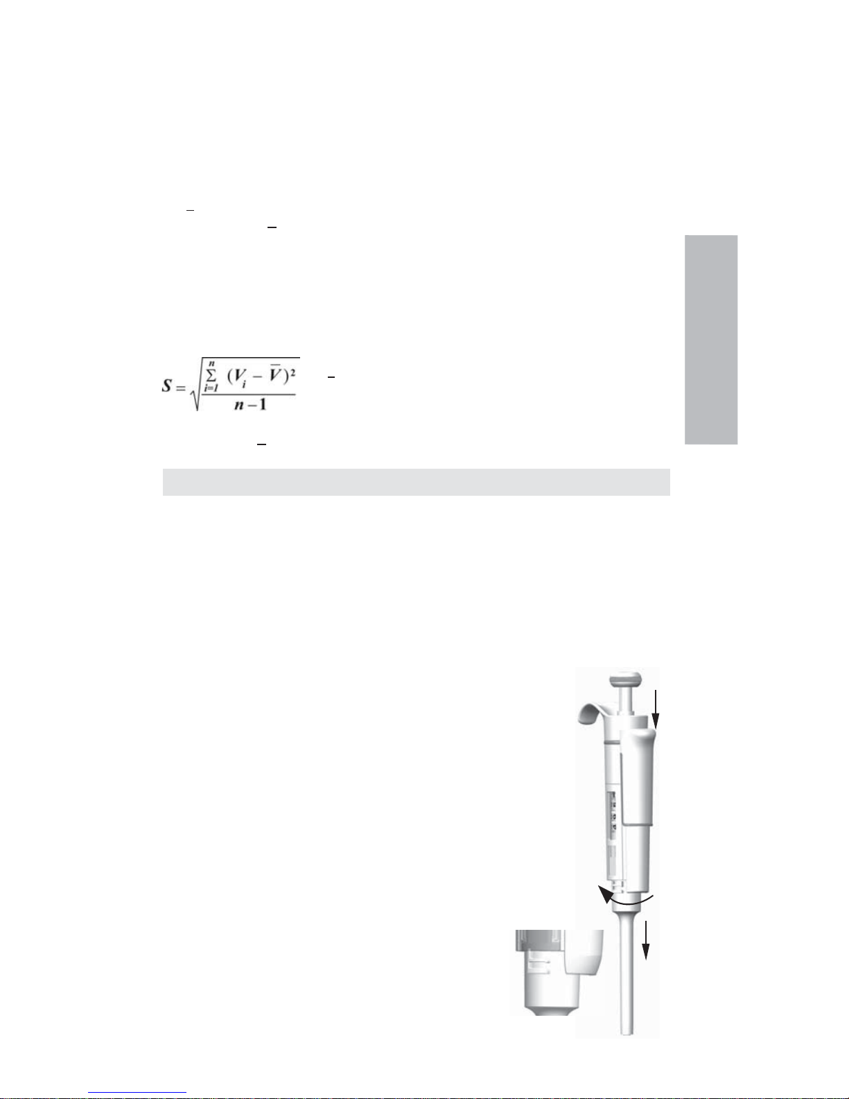
2-1000 μl pipettes
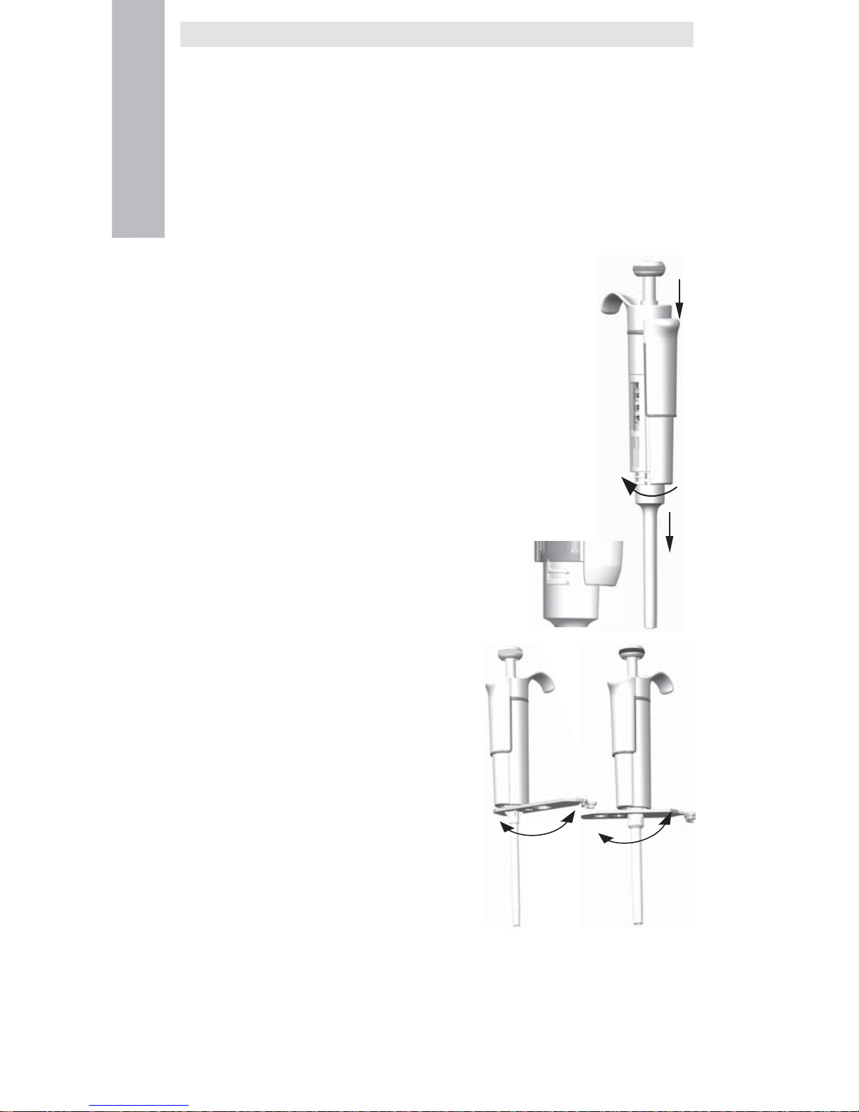
1. Press the tip ejector.
2. Rotate the tip ejector 11 counterclockwise and pull it out.
3. Turn out the tip cone counterclockwise with the service tool.
4. Pull out the piston and other parts. Push out with piston the rest of the
piston assembly. Then turn the tip cone upside down and tap all parts
from tip cone. Remember keep all parts in order on table for reassembly.
5. Clean the piston, the piston spring and the O-rings with a dry napless cloth.
6. Check the tip cone for foreign particles.
7. Grease the cleaned parts with the lubricant that comes with the pipette.
8. Reassemble the pipette components.
0.2-2μl, 0.5-5μl & 1-10 μl: First, slide spring 22, o-ring support 23 and
o-ring 24 on the tube 21. With the 0.2-2μl model insert the tube 27
into the tube 21. Then slide the spring 13, spring support 16
and tubes 17 and 18, bigger o-ring 19 and smaller o-ring 20
back on the piston.
Compress the spring with fi ngers by pressing piston and
spring support 16 against each other and slide
the tube 21 with rest of the parts on the piston.
Hold the spring compressed and carefully slide
the entire assembly into the tip cone and release
the spring.
2-20 μl & 5-50 μl: Slide the spring 13, spring
support 16 and tubes 17 and 18, bigger o-ring 19
and smaller o-ring 20 back on the piston.
Compress the spring with fi ngers by pressing
piston and spring support 16 against each other
and slide the bigger o-ring 19, smaller o-ring 20,
spring support 21 and the spring 22 (smaller
diameter against spring support 21) on the piston.
Hold the spring compressed and carefully slide
the entire assembly into the tip cone and release
the spring.
10-100 μl & 20-200 μl: Slide the spring 13, spring
support 16 and o-ring 17 back on the piston. Slide
the entire assembly into the tip cone.
100-1000μl: Put the o-ring 17 and support ring 16 to
the tip cone. Slide the spring 13 on the piston and
slide the entire assembly into the tip cone.
9. All: Put the spring 15 and support 14 on top of the tip cone and carefully insert the tip
cone assembly to the handle. Attach the tip cone by turning it fi rst clockwise tight by hand,
then do the fi nal tightening with the service tool.
10. Reassemble the tip ejector.
English
1000μl
2-300μl
1
3
2
Page 13
13
English
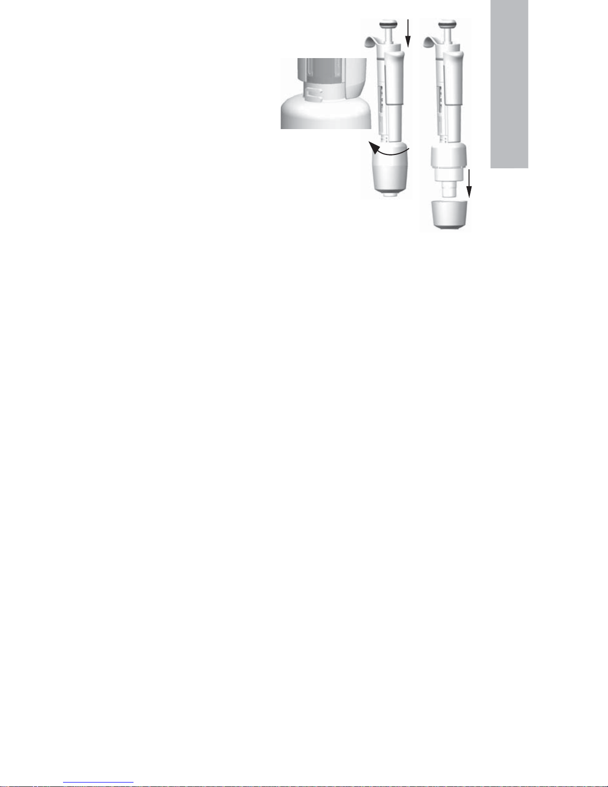
0.5-5ml & 1-10 ml pipettes
1. Press the tip ejector.
2. Rotate the tip ejector 10
counterclockwise to open it.
3. Disassemble the lower part of the tip
ejector 14 (snap fi tting).
4. Turn the cylinder 13 counterclockwise
and pull out the tip cone assembly.
5. Remove the cylinder 13 by pressing
the snaps fi ttings of the cylinder.
5. Clean and regrease the O-ring 12 and cylinder 13.
6. Assemble the parts in the opposite order of disassembly.
Long-term service, multichannel pipettes
If the pipette is used daily it should be checked and lubricated
every three months.
1. Place the service tool head#1 between ring 15 and ejector 23. Push the tool
until the partssnap from each other.
2. Check that the ejector lever is in up position and pull down the tip ejector part of the module.
Place the service tool head#2 in the hole of adapter tube 46.
3. Open the upper end of the tip ejector slightly and remove the tip ejector.
4. Screw out the module of the handle.
5. Remove the clip 22.
6. Press the spring 13 and remove the locking pieces 12 from the groove. Remove the spring 13.
7. Take off the locking claws 44 and 45 and pull out the adapter tube 46 and tube 43.
8. Use a screwdriver to remove the four screws 20,21 in the module cover and lift off
the cover.
9. Remove the piston bar 16 and clean the pistons 31 and tip cones 42 with a dry nap–free cloth.
10. If needed, service the tip cones:
16channel 1-10ul: The tip cones cannot be serviced, please replace if necessary.
30-300 μl, 10-100μl & 5-50 μl: Open the tip cone by carefully releasing the cover ring 32
from its snap joint with the screwdriver. Remove all the parts from the tip cone. Clean all
the parts. If needed, replace the o-rings. Take one piston. Slide the spring 33, cover ring 32
(larger hole), spring 34,, support ring 35, (o–ring 37 bigger 5-50μl/10-100μl) and o–ring 36
(smaller) onto the piston. Grease the o–ring with the lubricant provided in the pipette
package. Slide all the parts into the tip cone 30 and close the snap joint of the cover ring 32.
1–10 μl: Open the tip cone by carefully releasing the cover ring 32 from its snap joint with
the screwdriver. Remove all the parts from the tip cone. Clean all the parts. If needed,
replace the o-rings. Take one piston. Slide spring 33, cover ring 32 (larger hole), support 35,
o–ring 36 (bigger), o–ring 37 (smaller) and o–ring support 38 onto the piston. Then slide
spring 39, spring support 40 (sharp edges fi rst) and o–ring 41 onto the o–ring sup port 38.
Grease the o–rings with the lubricant provided in the pipette package. Slide all the parts
into the tip cone 30 and close the snap joint of the cover ring 32.
11. Install the piston bar with pistons and tip cones in the cover. Place aligning studs to the same
side when assembling the module. Close the cover with the four screws. Insert the clip 22.
12. Place the adapter tube 46 and tube 43 on the neck of the module and insert the locking
claws 44 and 45.
13. Insert spring 13 and locking pieces 12 to the piston rod 16.
14. Place the tip ejector on the module.
15. Screw the module in the handle and tighten with service tool head#2.
16. Push the tip ejector lever down, until you hear a “click”.
Service Instructions for Multichannel Pipette Tip Cones
To ensure even performance between all channels in a multichannel pipette, all tip cones have
to be changed at the same time, if any of them needs to be changed. Don’t mix tip cones of
different packages, because one bag contains a matched set of tip cones. Place aligning studs
to the same side when assembling the module. See picture on page 71.
1
2
3
Page 14

14
CAUTION!
The Finnpipette is designed to allow easy in-lab service. If you would prefer to
have us or your local representative service your pipette, please make sure that
the pipette has been decontaminated before you send it to us.
Please note that the postal authorities in your country may prohibit or restrict the
shipment of contaminated material by mail.
Sterilization
The tip cone assy of a single channel pipette can be repeatedly autoclaved at 121°C (252°F)
(2 ata) for 20 minutes. All other parts and the multichannel pipettes are not autoclavable. After
autoclaving the tip cone assy must be cooled to room temperature for at least two hours. Before
pipetting, make sure that the tip cone assy is dry. We recommend that you check the calibration
after every sterilization cycle.
Autoclavable parts:
Part number 42: single channel tip cone assy
Excluding part number 10 and 14 on 0.5-5ml and 1-10ml models
The part numbers are presented in section Spare Parts.
Trouble shooting
The table below lists possible problems and their solutions.
English
Defect
Leakage
Inaccurate
dispensing
Inaccurate
dispensing with
certain liquids
Dispensing knob
jammed to semi
down position
Possible reason
Tip incorrectly attached
Foreign particlesbetween tip and
tip cone
Foreign particles between the
piston, the O-ring and the cylinder
Insuffi cient amount of grease on
cylinder and O-ring
O-ring damaged
Incorrect operation
Tip incorrectly attached
Calibration altered: caused by
misuse, for example
Tip cone (Single channel) or
module (Multichannel) loose
Unsuitable calibration
High viscosity liquids may require
recalibration
One sided force applied to the knob
when adjusting the volume with one
hand
Solution
Attach fi rmly
Clean tip cones attach new tips
Clean and grease O-ring and
cylinder.
Grease accordingly
Change the O-ring
Follow instructions carefully
Attach fi rmly
Recalibrate according to
instructions
Tighten the tip cone or module
with the service tool.
Recalibrate with the liquids
in question
Pull up the knob and press down
again to locked position
Page 15

15
Deutsch
Produktbeschreibung
Finnpipette F1 ist eine stufenlos einstellbare Mehrzweck-Mikropipette zur Entnahme und
Ausgabe genauer Flüssigkeitsmengen.
Sie funktioniert auf der Basis des Luftverdrängungsprinzips (d. h. einer Luftschnittstelle) und
verwendet abnehmbare Einwegspitzen.
Das einstellbare Ablaufvolumen wird in einer digitalen Anzeige am Griff dargestellt.
Die vierzehn Pipettenmodelle von Finnpipette F1 umfassen einen Volumenbereich von 0,2μl bis 10ml.
Bestellnr. Volumen Farbcode Finntip
4641010N 0,2 μl bis 2 μl rosa Flex 10, 10, 20, 50
4641020N 0,5 μl bis 5 μl rosa Flex 10, 10, 20, 50
4641030N 1 μl bis 10 μl rosa Flex 10, 10, 20, 50
4641040N 1 μl bis 10 μl gelb
Flex 200, 250 Univ., 200 Ext, 300, Flex 300
4641050N 2 μl bis 20 μl
turquioise
50
4641060N 2 μl bis 20 μl gelb
Flex 200, 250 Univ., 200 Ext, 300, Flex 300
4641130N 5 μl bis 50 μl
turquioise
50
4641140N 5 μl bis 50 μl gelb
Flex 200, 250 Univ., 200 Ext, 300, Flex 300
4641070N 10 μl bis 100 μl gelb
Flex 200, 250 Univ., 200 Ext, 300, Flex 300
4641080N 20 μl bis 200 μl gelb
Flex 200, 250 Univ., 200 Ext, 300, Flex 300
4641090N 30 μl bis 300 μl orange Flex 300, 300
4641100N 100 μl bis 1000 μl blau Flex 1000, 1000, 1000 Ext
4641110N 0,5 ml bis 5 ml grün 5 ml
4641120N 1 ml bis 10 ml rot 10 ml, Flex 10 ml Ext
Die 13 Pipettenmodelle von Finnpipette F1 Fixed Volume umfassen einen Volumenbereich von
1μl bis 10ml.
Bestellnr. Volumen Farbcode Finntip
4651020N 10 μl dunkelblau Flex 200, 250 Univ., 200 Ext, 300, Flex 300
4651130N 20 μl dunkelblau Flex 200, 250 Univ., 200 Ext, 300, Flex 300
4651030N 25 μl dunkelblau Flex 200, 250 Univ., 200 Ext, 300, Flex 300
4651040N 50 μl dunkelblau Flex 200, 250 Univ., 200 Ext, 300, Flex 300
4651050N 100 μl dunkelblau Flex 200, 250 Univ., 200 Ext, 300, Flex 300
4651140N 200 μl dunkelblau Flex 200, 250 Univ., 200 Ext, 300, Flex 300
4651060N 250 μl dunkelblau Flex 1000, 1000, 1000 Ext
4651070N 500 μl dunkelblau Flex 1000, 1000, 1000 Ext
4651080N 1000 μl dunkelblau Flex 1000, 1000, 1000 Ext
4651090N 2000 μl dunkelblau 5 ml
4651100N 3000 μl dunkelblau 5 ml
4651110N 5000 μl dunkelblau 5 ml
4651120N 10000 μl dunkelblau 10 ml, Flex 10 ml Ext
Die zehn Pipettenmodelle von Finnpipette F1 Multichannel umfassen einen Volumenbereich von
1 μl bis 300 μl.
Bestellnr. Kanäle
Volume Range
Farbcode
Finntip
4661000N 8 1 μl bis 10 μl rosa Flex 10, 10, 20, 50
4661010N 8 5 μl bis 50 μl gelb
Flex 200, 250 Univ., 200 Ext, 300, Flex 300
4661020N 8 10 μl bis 100 μl gelb
Flex 200, 250 Univ., 200 Ext, 300, Flex 300
4661030N 8 30 μl bis 300 μl orange Flex 300, 300
4661040N 12 1 μl bis 10 μl rosa Flex 10, 10, 20, 50
4661050N 12 5 μl bis 50 μl gelb
Flex 200, 250 Univ., 200 Ext, 300, Flex 300
4661060N 12 10 μl bis 100 μl gelb
Flex 200, 250 Univ., 200 Ext, 300, Flex 300
4661070N 12 30 μl bis 300 μl orange Flex 300, 300
4661080N 16 1 μl bis 10 μl lila 20
4661090N 16 5 μl bis 50 μl
turquioise
50
Page 16
16
Deutsch
Digitalanzeige
Die einstellbare Ablaufmenge ist in der großen digitalen
Anzeige am Griff zu sehen.
Materialien
Die Finnpipette F1 wird aus mechanisch dauerhaften und chemisch beständigen Materialien
hergestellt.
Für Informationen zur Abfallentsorgung wenden Sie sich bitte an Ihre örtliche Umweltbehörde.
Für nähere Informationen wenden Sie sich bitte an info.pipettes@thermofi sher.com.
Beschreibung der Spitzen
Für die Verwendung mit der Finnpipette F1 werden Finntips empfohlen.
Sie bestehen aus neuem, naturfarbenem Polypropylen, dem allgemein einzigen nicht
kontaminierenden
Material, das für Spitzen geeignet ist. Finntips sind ebenfalls autoklavierbar
(121°C).
Packungsinhalt
Die Finnpipette F1 wird in einer speziell konzipierten Verpackung transportiert und enthält die
folgenden Bestandteile:
1. Die Finnpipette
2. Wartungswerkzeug
3. Wartungswerkzeug für Mehrkanalpipetten
4. Finntip-Probe
5. Schmiermittel (Bestellnr. 2203130)
6. Bedienungsanleitung
7. Kalibrierungszertifi kat / Garantiezertifi kat
8. Aufhängevorrichtung (Bestellnr. 2206040)
9. Zwei Aufkleber
Sicherheit
Warnungen sind mit diesem Symbol gekennzeichnet:
Vorgesehener Verwendungszweck
Die vorgesehene Verwendung des Produkts ist die Übertragung von Flüssigkeiten in Volumina
von 0,2 μl bis 10 ml.
Die Finnpipette F1 Pipette und die Finntips sind als Komponenten eines Analysesystems
konzipiert. Der Endbenutzer ist für die Validierung des Systems und die Sicherstellung korrekter
Ergebnisse verantwortlich.
Gesundheitsgefahren
Halten Sie die allgemeinen Sicherheitsvorschriften ein und tragen Sie angemessene
Schutzkleidung einschließlich Schutzbrille und -handschuhen.
Befolgen Sie bei der Entsorgung von Gefahrgut (z.B. radioaktive oder potentiell infektiöse
Substanzen) die Sicherheitsvorschriften und Laborregeln.
Die Pipette und ihre Spitzen sind nicht für In-vivo-Untersuchungen geeignet. Verwenden Sie
die Pipette niemals zum Injizieren von Flüssigkeiten in den menschlichen Körper.
Richten Sie die Pipette nicht auf Personen, wenn Sie die Spitze auswerfen.
Die Finnpipette F1 darf nur von geschultem Personal verwendet werden, das über entsprechende
Laborpraxis verfügt. Vor und während der Verwendung von Pipette und Spitze unbedingt die
Gebrauchsanleitung lesen! Die zulässige Betriebstemperatur der F1 liegt zwischen +4°C und
+40°C.
Page 17
17
Falsche Dispensierergebnisse
Mögliche Gründe für Abweichungen:
a. Pipettiermethode (Direktmodus empfohlen)
b. Temperatur (Luft, Flüssigkeit, Pipette und Spitze).
c. Druck
d. Feuchtigkeit
e. Bediener (z.B. Daumenbewegung, Pipettierwinkel)
f. Flüssigkeitsdichte, Viskosität und Dampfdruck
g. Art der Spitze
Wenn die Pipettierleistung für die medizinische Diagnose entscheidend ist, muss das
Ergebnis des Diagnosetests durch einen weiteren Test verifi ziert werden, möglichst in
alternativem Verfahren. Die Möglichkeit eines inkorrekten Ablaufvolumens beim Pipettieren
kann nicht völlig ausgeschlossen werden.
Um Fehler und/oder Leckagen zu verhindern, vergewissern Sie sich, dass die Spitze korrekt
an der Pipette befestigt ist.
Überschreiten Sie beim Drehen des Volumenreglers nicht den zulässigen Maximalwert.
Andernfalls kann die Pipette Schaden nehmen oder ungenaue Ergebnisse produzieren.
Für wiederverwendete Pipettenspitzen wird keine Leistungsgarantie übernommen.
Die Farbcodierung von Pipette und Spitze muss übereinstimmen.
Entsorgung der Materialien
Befolgen Sie bei der Entsorgung biologischen Gefahrguts und radioaktiver Abfälle sowohl die
laborspezifi schen als auch die nationalen Vorschriften. Beachten Sie außerdem die örtlichen
Vorschriften für die Entsorgung infektiösen Materials.
Warnung Die Proben können ansteckende Keime enthalten. Entsorgen Sie alle Einwegspitzen
als biologisches Gefahrgut.
Warnung Dekontaminieren Sie die Pipette vor der Entsorgung.
Für Informationen zur Abfallentsorgung wenden Sie sich bitte an Ihre örtliche Umweltbehörde.
Für nähere Informationen wenden Sie sich bitte an info.pipettes@thermofi sher.com.
Bitte führen Sie die Originalverpackung und das darin enthaltene Verpackungsmaterial
sachgerechtem Recycling zu.
Weitere Informationen erhalten Sie bei Ihrer örtlichen Vertretung von ThermoFisher Scientifi c.
Bedienung der Pipette
Einstellen der Ablaufmenge
1. Die Ablaufmenge wird mit dem Knopf am oberen Ende der
Pipette eingestellt. Ziehen Sie den Knopf nach oben, um die
Mengeneinstellung zu aktivieren.
2. Um die Ablaufmenge zu erhöhen, drehen Sie den Knopf gegen
den Uhrzeigersinn. Um die Ablaufmenge zu verringern, drehen
Sie ihn im Uhrzeigersinn.
3. Vergewissern Sie sich, dass die gewünschte Mengeneinstellung
einrastet.
4. Wählen Sie keine Ablaufmenge, die außerhalb des für die Pipette
zulässigen Bereichs liegt.
Durch das gewaltsame Drehen des Knopfs außerhalb des Bereichs kann
der Mechanismus beschädigt und die Pipette unbrauchbar werden.
5. Arretieren Sie die Mengeneinstellung, indem Sie den Knopf drücken.
Kennschild
Die Pipette ist mit einem Kennschild versehen, auf dem Sie Anwendung,
Kalibrierungsdatum, Ihre Initialen usw. vermerken können. Entfernen Sie
zum Austauschen des Kennschilds das Pipettenmodul. Beschriften Sie das
Etikett mit Bleistift und schieben Sie das Kennschild zusammen mit der
Halterung wieder in den Schlitz.
Deutsch
+
1
2
Page 18
18
Auswerfen der Spitze
Um die Gefahr einer Kontamination auszuschließen, ist jede Pipette mit einem
Spitzen-Auswurfsystem ausgestattet. Um die Spitze zu lösen, halten Sie die Pipette
über einen geeigneten Abfallbehälter und drücken Sie den Spitzenauswerfer mit
dem Daumen nach unten.
Anpassung der Fingerstütze
Die Fingerstütze kann von der Mittelposition in beide
Richtungen um 60° gedreht werden. Für Rechtshänder
empfi ehlt es sich, die Stütze ein Stück weit nach links zu
drehen (gegen den Uhrzeigersinn), um die bestmögliche
Position für den Daumen zum Auswerfen der Spitze
einzustellen. Siehe Abbildung.
Pipettiermethoden
Das Drücken und Loslassen des Bedienungsknopfes muss stets langsam erfolgen,
insbesondere wenn mit hochviskosen Flüssigkeiten gearbeitet wird. Achten Sie
darauf, dass der Bedienungsknopf nie zurückschnappt.
Stellen Sie sicher, dass die Spitze fest in der Spitzenhalterung sitzt. Kontrollieren
Sie die Spitze auf Fremdkörper.
Bevor Sie mit dem Pipettieren beginnen, füllen und entleeren Sie die Spitze 2 3 Mal mit der Lösung, die Sie pipettieren wollen. Halten Sie die Pipette beim Ansaugen der
Flüssigkeit senkrecht. Ihr Zeigefi nger sollte auf dem griffi gen Bereich liegen. Achten Sie darauf,
dass die Spitze, die Pipette und die Lösung dieselbe Temperatur aufweisen.
Vorwärtsmethode
Füllen Sie ein sauberes Reagenzglas mit der Flüssigkeit, die pipettiert werden soll.
1. Drücken Sie den Knopf bis zum ersten Anschlag.
2. Tauchen Sie die Spitze ca. 1 cm unter die Oberfl äche der Flüssigkeit im Reagenzglas und
lassen Sie den Knopf langsam los. Nehmen Sie die Spitze aus der Flüssigkeit, wobei Sie
überschüssige Flüssigkeit am Rand des Glases abstreifen.
3. Gießen Sie die Flüssigkeit aus, indem Sie den
Knopf sanft bis zum ersten Anschlag drücken.
Drücken Sie nach etwa einer Sekunde den Knopf
ganz bis zum zweiten Anschlag durch. Dadurch
wird die Spitze entleert.
4. Lassen Sie den Knopf in die Ausgangsposition
zurückgleiten. Wechseln Sie nötigenfalls die
Spitze und fahren Sie mit dem Pipettieren fort.
Rückwärtsmethode
Die Rückwärtsmethode ist geeignet für Flüssigkeiten, die eine hohe Viskosität aufweisen oder
leicht schäumen. Diese Methode wird auch empfohlen, wenn nur sehr kleine Mengen verteilt
werden sollen. Füllen Sie ein sauberes Reagenzglas mit der Flüssigkeit, die pipettiert werden soll.
1. Drücken Sie den Knopf ganz durch bis zum zweiten Anschlag.
2. Tauchen Sie die Spitze ca. 1 cm unter die Oberfl äche der Flüssigkeit im Reagenzglas und
lassen Sie den Knopf langsam los. Dadurch wird die Spitze gefüllt. Nehmen Sie die Spitze
aus der Flüssigkeit, wobei Sie überschüssige Flüssigkeit am Rand des Glases abstreifen.
3. Gießen Sie die voreingestellte Flüssigkeitsmenge
aus, indem Sie den Knopf sanft bis zum ersten
Anschlag drücken. Halten Sie den Knopf am
ersten Anschlag fest. In der Spitze verbleibt etwas
Flüssigkeit, die nicht ausgegossen werden darf.
4. Die restliche Flüssigkeit wird entweder mit der
Spitze entsorgt oder zurück in den
Flüssigkeitsbehälter gegossen.
Wiederholungsmethode
Die Wiederholungsmethode bietet eine rasche und einfache Möglichkeit, dasselbe Volumen
mehrmals zu dosieren. Füllen Sie ein sauberes Reagenzglas mit der Flüssigkeit, die pipettiert
werden soll.
Deutsch
1 2 3 4
1 2 3 4
Page 19
19
Deutsch
1. Drücken Sie den Knopf ganz durch bis zum
zweiten Anschlag.
2. Tauchen Sie die Spitze ca. 1 cm unter die
Oberfl äche der Flüssigkeit im Reagenzglas und
lassen Sie den Knopf langsam los. Dadurch wird
die Spitze gefüllt.
Nehmen Sie die Spitze aus der Flüssigkeit, wobei
Sie überschüssige Flüssigkeit am Rand des Glases
abstreifen.
3. Gießen Sie die voreingestellte Flüssigkeitsmenge
aus, indem Sie den Knopf sanft bis zum
ersten Anschlag drücken. Halten Sie den Knopf am ersten Anschlag fest. In der Spitze
verbleibt etwas Flüssigkeit, die nicht ausgegossen werden darf.
4. Fahren Sie mit dem Pipettieren fort, indem Sie die Schritte 3 und 4 wiederholen.
Pipettierung heterogener Proben
(z. B. Deproteinisation bei der Bestimmung des Blutzuckers)
Befolgen Sie Schritt 1 und 2 der Vorwärtsmethode um die Spitze mit Blut zu füllen.
Wischen Sie die Spitze sorgfältig mit einem trockenen, sauberen Tuch ab.
1. Tauchen Sie die Spitze in das Reagenzglas ein und drücken Sie den Knopf bis zum ersten
Anschlag. Achten Sie dabei darauf, dass die
Spitze unter die Oberfl äche der Flüssigkeit
eingetaucht ist.
2. Lassen Sie den Knopf langsam in die
Ausgangsposition zurückgleiten.
Dadurch wird die Spitze gefüllt. Halten Sie die
Spitze weiterhin in der Lösung.
3. Drücken Sie den Knopf bis zum ersten Anschlag
und lassen Sie ihn langsam los. Wiederholen Sie
diesen Vorgang, bis die Innenwand der Spitze klar ist.
4. Drücken Sie zum Schluss den Knopf ganz bis zum zweiten Anschlag durch, um die Spitze
vollständig zu entleeren.
Kalibrierung und Justierung
Alle Finnpipetten werden im Werk auf die spezifi zierten Mengen an destilliertem oder
vollentsalztem Wasser bei Verwendung der Vorwärtsmethode kalibriert und justiert.
Beachten Sie, dass die Verwendung anderer Pipettiermethoden die Kalibrierungsergebnisse
beeinfl ussen können. Die Pipetten sind so konzipiert, dass eine erneute Justierung für andere
Pipetiermethoden oder Flüssigkeiten vorgenommen werden kann, die eine unterschiedliche
Temperatur und Viskosität aufweisen.
Erforderliche Geräte und Prüfbedingungen
Zur Überprüfung wird eine Analysenwaage benötigt. Der Skalenwert der Waage muss
entsprechend der gewählten Testmenge der Pipette gewählt werden:
Menge Skala
unter 10 μl 0,001 mg
10-100μl 0,01 mg
über 100 μl 0,1 mg
Testfl üssigkeit: Destilliertes oder vollentsalztes Wasser der Klasse 3 gemäß ISO 3696. Die
Überprüfung wird in einem zugluftfreien Raum bei einer konstanten Temperatur von 15°C bis
30°C (±0,5°C) des Wassers, der Pipette und der Luft durchgeführt. Die relative Luftfeuchtigkeit
muss über 50% liegen. Insbesondere bei Mengen unter 50 μl sollte die Luftfeuchtigkeit möglichst
hoch sein, um Verdunstungsverluste zu vermeiden. Die Verwendung von Spezialzubehör, z.B.
eines Verdunstungsschutzes, wird empfohlen.
Prüfen der Kalibrierung
Die Pipette wird mit der Höchstmenge (Nennvolumen) und der Mindestmenge geprüft. Zuerst
wird eine neue Spitze drei- bis fünfmal mit Flüssigkeit durchspült. Dann wird mit beiden Mengen
eine Serie von zehn Pipettierungen durchgeführt. Eine Pipette ist stets auf den Ablauf (Ex) der
gewählten Menge justiert. Die Verwendung der Vorwärtsmethode wird empfohlen.
1 2 3 4
1 2 3 4 5
Page 20

20
Deutsch
Die maximal zulässigen Abweichungen beziehen sich auf die Vorwärtsmethode. Es wird
empfohlen alle Kanäle einer Mehrkanalpipette zu kalibrieren, hilfsweise können auch nur die
Randkanäle kalibriert werden. Anpassungen werden dann mit den mittleren Kanälen vorgenommen.
Wir empfehlen die ISO8655 Kalibriergrenzen zu verwenden, wie in nachfolgenden Tabellen
aufgeführt. Alternativ können anwenderspezifi sche Kalibriergrenzen angewendet werden.
Vorgang:
1. Nehmen Sie 10 Pipettierungen mit der Mindestmenge vor.
2. Nehmen Sie 10 Pipettierungen mit der Höchstmenge vor.
3. Berechnen Sie die Ungenauigkeit (A) und die Unpräzision (cv) beider Serien.
4. Vergleichen Sie die Ergebnisse mit den Fehlergrenzen.
Wenn sich die berechneten Werte innerhalb der festgelegten Fehlergrenzen befi nden, ist die
Kalibrierung der Pipette korrekt.
Kalibrierungsgrenzwerte nach ISO8655
Die Spezifi kationen von Thermo Scientifi c Finnpipette F1 entsprechen ISO8655
Finnpipette F1-Einzelkanalpipette mit variablem Volumen
Bereich Volumen Ungenauigkeit Unpräzision
μl μl % s.d. μl cv%
0,2-2 μl 2 ±0.080 ±4 0.040 2.0
0.2 ±0.080 ±40 0.040 20.0
0,5-5 μl 5 ±0.125 ±2.5 0.075 1.5
0.5 ±0.125 ±25 0.075 15
1-10 μl 10 ±0.120 ±1.2 0.080 0.8
1 ±0.120 ±12 0.080 8.0
2-20 μl 20 ±0.20 ±1.0 0.10 0.5
2 ±0.20 ±10.0 0.10 5.0
5-50 μl 50 ±0.50 ±1.0 0.20 0.4
5 ±0.50 ±10 0.20 4.0
10-100 μl 100 ±0.80 ±0.8 0.30 0.3
10 ±0.80 ±8.0 0.30 3.0
20-200 μl 200 ±1.60 ±0.8 0.60 0.3
20 ±1.60 ±8.0 0.60 3.0
30-300 μl 300 ±4.0 ±1.3 1.5 0.5
30 ±4.0 ±13 1.5 5.0
100-1000 μl 1000 ±8.0 ±0.8 3.0 0.3
100 ±8.0 ±8.0 3.0 3.0
0,5-5 ml 5000 ±40.0 ±0.8 15.0 0.3
500 ±40.0 ±8.0 15.0 3.0
1-10 ml 10000 ±60.0 ±0.6 30.0 0.3
1000 ±60.0 ±6.0 30.0 3.0
Finnpipette F1-Einzelkanalpipette mit Konstantvolumen
Fixed Volume Ungenauigkeit Unpräzision
μl μl % s.d.μl cv%
10 ±0.120 ±1.20 0.080 0.80
20 ±0.20 ±1.00 0.10 0.50
25 ±0.50 ±2.00 0.20 0.80
50 ±0.50 ±1.00 0.20 0.40
100 ±0.80 ±0.80 0.30 0.30
200 ±1.60 ±0.80 0.60 0.30
250 ±4.00 ±1.60 1.50 0.60
500 ±4.00 ±0.80 1.50 0.30
1000 ±8.00 ±0.80 3.00 0.30
2000 ±16.0 ±0.80 6.00 0.30
3000 ±40.0 ±1.33 15.00 0.50
5000 ±40.0 ±0.80 15.00 0.30
10000 ±60.0 ±0.60 30.00 0.30
Page 21

21
Deutsch
Finnpipette F1-Mehrkanalpipette mit variablem Volumen
Bereich Kanal Volumen Ungenauigkeit Unpräzision
μl μl % s.d.μl cv%
1-10 μl 8, 12, 16 10 ±0.24 ±2.4 0.16 1.6
1 ±0.24 ±24 0.16 16
5-50 μl 8, 12, 16 50 ±1.0 ±2.0 0.4 0.8
5 ±1.0 ±20 0.4 8.0
10-100 μl 8, 12 100 ±0.80 ±0.8 0.30 0.3
10 ±0.80 ±8.0 0.30 3.0
30-300 μl 8, 12 300 ±8.0 ±2.7 3.0 1.0
30 ±8.0 ±26.7 3.0 10.0
Grenzwerte laut Herstellerspezifi kation
Finnpipette F1-Einzelkanalpipette mit variablem Volumen
Hersteller
Bereich Volumen Ungenauigkeit Unpräzision
Kalibrier-
μl μl % s.d. μl cv% Spitze
0.2-2 μl 2 ±0,050 ±2,50 0,040 2,00 Flex 10
0,2 ±0,024 ±12,00 0,020 10,00
0.5-5 μl 5 ±0,075 ±1,50 0,050 1,00 Flex 10
0,5 ±0,030 ±6,00 0,025 5,00
1-10 μl, micro 10 ±0,100 ±1,00 0,050 0,50 Flex 10
1 ±0,025 ±2,50 0,020 2,00
1-10 μl 10 ±0,100 ±1,00 0,080 0,80 Flex 200
1 ±0,035 ±3,50 0,030 3,00
2-20 μl, micro 20 ±0,20 ±1,00 0,08 0,40 50
2 ±0,06 ±3,00 0,05 2,50
2-20 μl 20 ±0,20 ±1,00 0,08 0,40 Flex 200
2 ±0,06 ±3,00 0,05 2,50
5-50 μl, micro 50 ±0,30 ±0,60 0,15 0,30 50
5 ±0,15 ±3,00 0,125 2,50
5-50 μl 50 ±0,30 ±0,60 0,15 0,30 Flex 200
5 ±0,15 ±3,00 0,125 2,50
10-100 μl 100 ±0,80 ±0,80 0,20 0,20 Flex 200
10 ±0,30 ±3,00 0,10 1,00
20-200 μl 200 ±1,2 ±0,60 0,4 0,20 Flex 200
20 ±0,36 ±1,80 0,14 0,70
30-300 μl 300 ±1,8 ±0,60 0,6 0,20 Flex 300
30 ±0,45 ±1,50 0,18 0,60
100-1000 μl 1000 ±6,0 ±0,60 2,0 0,20 Flex 1000
100 ±1,0 ±1,00 0,6 0,60
0,5-5 ml 5000 ±25,0 ±0,50 10,0 0,20 5 ml
500 ±10,0 ±2,00 4,0 0,80
1-10 ml 10000 ±50,0 ±0,50 20,0 0,20 10 ml
1000 ±20,0 ±2,00 8,0 0,80
Page 22
22
Deutsch
Finnpipette F1-Einzelkanalpipette mit Konstantvolumen
Hersteller
Fixed Volume Ungenauigkeit Unpräzision Kalibrier μl μl % s.d. μl cv% Spitze
10 ±0,090 ±0,90 0,080 0,80 Flex 200
20 ±0,14 ±0,70 0,10 0,50 Flex 200
25 ±0,15 ±0,60 0,125 0,50 Flex 200
50 ±0,30 ±0,60 0,20 0,40 Flex 200
100 ±0,40 ±0,40 0,30 0,30 Flex 200
200 ±0,80 ±0,40 0,60 0,30 Flex 200
250 ±1,0 ±0,40 0,75 0,30 Flex 1000
500 ±1,5 ±0,30 1,5 0,30 Flex 1000
1000 ±3,0 ±0,30 3,0 0,30 Flex 1000
2000 ±6,0 ±0,30 4,0 0,20 5 ml
3000 ±9,0 ±0,30 6,0 0,20 5 ml
4000 ±12,0 ±0,30 8,0 0,20 5 ml
5000 ±15,0 ±0,30 10,0 0,20 5 ml
10000 ±30,0 ±0,30 20,0 0,20 10 ml
Finnpipette F1-Mehrkanalpipette mit variablem Volumen
Hersteller
Bereich Kanal Volumen Ungenauigkeit Unpräzision Kalibrier μl μl % s.d. μl cv% Spitze
1.0-10 μl 8, 12, 16 10 ±0,240 ±2,40 0,160 1,60 Flex 10
1 ±0,120 ±12,00 0,080 8,00
5-50 μl 8, 12, 16 50 ±0,75 ±1,50 0,35 0,70 Flex 200
5 ±0,25 ±5,00 0,10 2,00
10-100 μl 8, 12 100 ±1,30 ±1,30 0,50 0,50 Flex 200
10 ±0,50 ±5,00 0,20 2,00
30-300 μl 8, 12 300 ±3,0 ±1,00 0,9 0,30 Flex 300
30 ±1,5 ±5,00 0,6 2,00
Justierung
Die Einstellung wird nur für ein Volumen vorgenommen. Als Einstellvolumen wird die Mindestoder 10% der Höchstmenge empfohlen. Bei Mehrkanal Pipetten wird zur Anpassung einer der
mittleren Kanäle verwendet.
1. Stecken Sie das Werkzeug in die Öffnungen der
Eichungsschraube am oberen Ende des Griffs.
2. Drehen Sie das Werkzeug im Uhrzeigersinn, um
die Menge zu erhöhen, oder gegen den
Uhrzeigersinn, um die Menge zu verringern.
3. Überprüfen Sie nach der Justierung die
Kalibrierung gemäß der oben beschriebenen
Anleitung.
Formeln zum Berechnen von Werten
Umrechnung von Masse in Volumen
V = (w + e) x Z V = Volumen (μl)
w = Gewicht (mg)
e = Verdunstungsverlust (mg)
Z = Umrechnungsfaktor für μl/mg-Konversion
Verdunstungsverluste können bei kleinen Mengen ausschlaggebend sein. Um den Volumenverlust
zu bestimmen, leeren Sie Wasser in die Waagschale, notieren Sie den Anzeigewert und starten
Sie eine Stoppuhr. Stellen Sie fest, um wie viel der angezeigte Wert während 30 Sekunden
abnimmt (z.B. 6 mg = 0,2 mg/s).
+
Page 23
23
Deutsch
Vergleichen Sie dies mit der Pipettierzeit vom Austarieren bis zum Ablesen. Normalerweise
beträgt die Pipettierzeit 10 Sekunden. Der Volumensverlust beträgt in diesem Fall deshalb 2 mg
(10 s x 0,2 mg/s). Wird ein Verdunstungsschutz oder Deckel für das Gefäß verwendet, ist ein
Korrigieren der Verdampfungsmenge normalerweise nicht nötig.
Der Faktor Z dient zur Umrechnung des Gewichts von Wasser auf sein Volumen bei
Prüftemperatur und Prüfdruck. Ein typischer Wert ist 1,0032 μl/mg bei 22°C und 95 kPa. Siehe
die Umwandlungstabelle auf Seite 62.
Ungenauigkeit (systematischer Fehler)
Ungenauigkeit bezeichnet die Differenz zwischen der abgegebenen Menge und dem gewählten
Volumen einer Pipette.
A = V - V
0
A = Ungenauigkeit
V = Mittleres Volumen
V
0
= Nennvolumen
Ungenauigkeit kann als relativer Wert dargestellt werden: A% = 100% x A / V
0
Unpräzision (statistischer Fehler)
Unpräzision bezieht sich auf die Wiederholbarkeit der Pipettierung. Sie wird als
Standardabweichung (s) oder Variationskoeffi zient (cv) angegeben.
s = Standardabweichung
v = Mittleres Volumen
n = Anzahl der Messungen
Die Standardabweichung kann als relativer Wert dargestellt werden (CV)
CV = 100% x S / V
Wartung
Wenn die Finnpipette F1 nicht in Verwendung ist, muss sie in einer senkrechten Position
aufbewahrt wird. Wir empfehlen dafür eine Finnpipette-Halterung.
Die angegebenen Teilenummern beziehen sich auf die Explosionszeichnungen ab Seite 63.
Kurzfristige Wartung
Die Außenfl äche der Pipette sollte täglich vor Gebrauch auf Staub und Schmutz kontrolliert werden.
Insbesondere der Spitzenkegel sollte gründlich untersucht werden. Zur Reinigung der Pipette
darf ausschließlich 70% Ethylalkohol verwendet werden.
Langfristige Wartung, Einzelkanalpipetten
Wird die Pipette täglich verwendet, sollte sie alle drei Monate inspiziert
werden. Die Wartung beginnt mit dem Zerlegen der Pipette.
Pipetten von 2-1000 μl
1. Drücken Sie den Spitzenauswerfer
2. Drehen Sie den Spitzenauswerfer 11 gegen den Uhrzeigersinn und
ziehen Sie ihn heraus.
3. Drehen Sie den Spitzenkegel mit Hilfe des Wartungswerkzeugs gegen
den Uhrzeigersinn aus dem Gewinde.
4. Ziehen Sie den Kolben und die übrigen Teile heraus. Drücken Sie mit
dem Kolben die übrigen Teile der Kolbenbaugruppe heraus. Drehen Sie
den Spitzenkegel um und klopfen Sie leicht auf ihn, so dass die darin
befi ndlichen Teile herausrutschen. Bewahren Sie die Teile so auf dem
Arbeitstisch auf, dass Sie sie beim Wiedereinbau in der richtigen
Reihenfolge griffbereit haben.
5. Reinigen Sie den Kolben, die Kolbenfeder und die O-Ringe mit einem
trockenen, fusselfreien Tuch.
6. Kontrollieren Sie den Spitzenkegel auf Fremdkörper.
7. Schmieren Sie die gesäuberten Teile mit dem Schmiermittel,
das mit der Pipette geliefert wird.
8. Bauen Sie danach die Pipettenkomponenten wieder zusammen.
1
3
2
Page 24

24
Deutsch
0,2-2 μl, 0,5-5 μl & 1-10 μl: Schieben Sie zuerst
die Feder 22, die O-Ring-Stütze 23 und den O-Ring
24 auf die Röhre 21.
0,2-2 μl-Modell: Schieben Sie die Röhre 27 in die
Röhre 21. Schieben Sie danach die Feder 13, die
Federstütze 16, die Röhren 17 und 18, den größeren
O-Ring 19 sowie den kleineren O-Ring 20 wieder
auf den Kolben.
Drücken Sie die Feder mit den Fingern zusammen,
indem Sie den Kolben und die Federstütze 16
gegeneinander drücken, und schieben Sie auch die
Röhre 21 auf den Kolben. Halten Sie die Feder
gedrückt und schieben Sie die ganze Baugruppe
vorsichtig in den Spitzenkegel. Danach können Sie
die Feder loslassen.
2-20 μl und 5-50 μl: Schieben Sie die Feder
13, die Federstütze 16, die Röhren 17 und 18,
den größeren O-Ring 19 sowie den kleineren
O-Ring 20 wieder auf den Kolben. Drücken Sie die
Feder mit den Fingern zusammen, indem Sie den
Kolben und die Federstütze 16 gegeneinander drücken, und schieben Sie den größeren
O-Ring 19, den kleineren O-Ring 20, die Federstütze 21 und die Feder 22 (den kleineren
Durchmesser der Federstütze 21 zugewandt) auf den Kolben. Halten
Sie die Feder gedrückt und schieben Sie die ganze Baugruppe vorsichtig in den
Spitzenkegel. Danach können Sie die Feder loslassen.
10-100 μl und 20-200 μl: Schieben Sie die Feder
13, die Federstütze 16 und den O-Ring 17 wiede auf den Kolben. Schieben Sie die ganze
Baugruppe in den Spitzenkegel.
100-1000 μl: Schieben den O-Ring 17 und den Stützring 16 in den Spitzenkegel. Schieben
Sie die Feder 13 auf den Kolben und danach die ganze Baugruppe in den Spitzenkegel.
9. Alle: Setzen Sie die Feder 15 und die Stütze 14 auf den Spitzenkegel. Schieben Sie die
Spitzenkegeleinheit vorsichtig in den Griff. Bringen Sie den Spitzenkegel an, indem sie
diesen zunächst mit der Hand im Uhrzeigersinn drehen und anschließend mit dem
Wartungswerkzeug festziehen.
10. Bauen Sie den Spitzenauswerfer wieder ein.
Pipetten von 0,5-5 ml und 1-10 ml
1. Drücken Sie auf den Spitzenauswerfer.
2. Öffnen Sie den Spitzenauswerfer 10, indem Sie ihn gegen den Uhrzeigersinn drehen.
3. Nehmen Sie das Unterteil des Spitzenauswerfers 14
auseinander (Einschnapphalterung).
4. Drehen Sie den Zylinder 13 gegen den Uhrzeigersinn und
ziehen Sie die Spitzenkegelbaugruppe heraus.
5. Entfernen Sie den Zylinder, indem
Sie auf dessen Einschnapphalterung
drücken.
5. O-Ring 12 und Zylinder 13 reinigen
und schmieren.
6. Bauen Sie die Teile in umgekehrter
Reihenfolge wieder ein.
Langfristige Wartung,
Mehrkanalpipetten
Falls die Pipette täglich verwendet wird, sollte sie alle drei
Monate überprüft und geschmiert werden.
1. Stecken Sie den Wartungswerkzeugkopf #1 zwischen Ring 15 und
Auswerfer 23. Drücken Sie das Werkzeug, bis sich die Teile
voneinander lösen.
2. Achten Sie darauf, dass der Auswerferhebel in der oberen Position ist, und ziehen Sie den
Auswerferbreich des Moduls nach unten.
Stecken Sie den Werkzeugkopf #2 in das Loch der Adapterröhre 46.
1
2
3
1000μl
2-300μl
Page 25

25
3. Öffnen Sie das untere Ende des Spitzenauswerfers ein kleines Stück weit und nehmen Sie
den Auswerfer heraus.
4. Schrauben Sie das Modul aus dem Griff.
5. Entfernen Sie die Klemme 22 heraus.
6. Drücken Sie die Feder 13 und lösen Sie die Arretierungen 12 aus der Nut. Entfernen Sie die
Feder 13.
7. Entfernen Sie die Arretierungskrallen 44 und 45 und ziehen Sie die Adapterröhre 46 sowie
die Röhre 43 heraus
8. Lösen Sie mit einem Schraubenzieher die vier Schrauben 20, 21 der Modulabdeckung und
entfernen Sie die Abdeckung.
9. Entfernen Sie die Kolbenstange 16 und reinigen Sie Kolben 31 und Spitzenkegel 42 mit
einem trockenen, fusselfreien Tuch.
10. Warten Sie bei Bedarf die Spitzenkegel:
16-Kanal-Pipetten, 1-10 μl: Die Wartung der Spitzenkegel ist nicht möglich. Bitte
ersetzen Sie verschlissene Kegel durch neue.
30-300 μl, 10-100μl & 5-50 μl: Öffnen Sie den Spitzenkegel, indem Sie den Schutzring 32
vorsichtig mit einem Schraubenzieher aus der Einschnapphalterung lösen. Nehmen Sie alle
Teile aus dem Spitzenkegel. Säubern Sie sämtliche Teile. Wechseln Sie bei Bedarf die
O-Ringe aus. Nehmen Sie einen Kolben. Schieben Sie die Feder 33, den Schutzring 32
(größeres Loch), die Feder 34, den Stützring 35, den O-Ring 37 (größer, 5-50μl/10-100μl) und
den O-Ring 36 (kleiner) auf den Kolben. Schmieren Sie den O-Ring mit dem Schmiermittel,
das mit der Pipette geliefert wird. Schieben Sie alle Teile in den Spitzenkegel 30 und
schließen Sie die Einschnapphalterung des Schutzrings 32.
1-10 μl: Öffnen Sie den Spitzenkegel, indem Sie den Schutzring 32 vorsichtig mit einem
Schraubenzieher aus der Einschnapphalterung lösen. Nehmen Sie alle Teile aus dem
Spitzenkegel. Säubern Sie sämtliche Teile. Wechseln Sie bei Bedarf die O-Ringe aus.
Nehmen Sie einen Kolben. Schieben Sie die Feder 33, den Schutzring 32 (größeres Loch),
die Stütze 35, den O-Ring 36 (größer), den O-Ring 37 (kleiner) sowie die O-Ringstütze 38
auf den Kolben. Schieben Sie danach die Feder 39, die Federstütze 40 (scharfe Kante
zuerst) und den O-Ring 41 auf die O-Ringstütze 38. Schmieren Sie die O-Ringe mit dem
Schmiermittel, das mit der Pipette geliefert wird. Schieben Sie alle Teile in den
Spitzenkegel 30 und schließen Sie die Einschnapphalterung des Schutzrings 32.
11. Setzen Sie Kolbenstange, Kolben und Spitzenkegel in die Abdeckung ein. Positionieren Sie
die Ausrichtungsbolzen beim Zusammensetzen des Moduls auf derselben Seite. Befestigen
Sie die Abdeckung mit den vier Schrauben. Setzen Sie die Klemme 22 ein.
12. Setzen Sie die Adapterröhre 46 und die Röhre 43 auf den Hals des Moduls und bringen Sie
die Arretierungskrallen 44 und 45 an.
13. Setzen Sie die Feder 13 und die Arretierungen 12 in die Kolbenstange 16 ein.
14. Setzen Sie den Spitzenauswerfer auf das Modul.
15. Schrauben Sie das Modul in den Griff und ziehen Sie es mit Werkzeugkopf #2 fest an.
16. Drücken Sie den Spitzenauswerferhebel nach unten, bis Sie ein Klickgeräusch hören.
Wartung der Multichannel-Pipettenspitzenkoni
Um die gleichmäßige Funktion aller Kanäle der Multichannel-Pipette sicherzustellen, müssen stets
alle Spitzenkoni gleichzeitig ausgetauscht werden. Verwenden Sie keinesfalls eine Kombination
von Spitzenkoni aus verschiedenen Packungen, da die in einer Packung enthaltenen Spitzenkoni
jeweils genau aufeinander abgestimmt sind. Positionieren Sie die Ausrichtungsbolzen beim
Zusammensetzen des Moduls auf derselben Seite. Siehe Abbildung auf Seite 71.
Sterilisierung
Die Spitze einer Einkanal-Pipette kann wiederholt bei 121°C (252°F) (2 ata) 20 Minuten lang
autoklaviert werden. Alle anderen Teile sowie Mehrkanalpipetten können nicht autoklaviert
werden. Nach dem Autoklavieren muss die Spitze für mindestens zwei Stunden auf
Zimmertemperatur abgekühlt werden. Die Spitze muss vor dem Pipettieren trocken sein. Wir
empfehlen, die Kalibrierung nach jedem Sterilisationszyklus zu überprüfen.
Autoklavierbare Teile:
Teilenummer 42: Einkanal-Spitze
Ausgenommen sind Teile mit den Nummern 10 und 14 bei den Modellen 0,5–5 ml und 1–10 ml.
Die Teilenummern werden im Bereich Ersatzteile aufgeführt.
Deutsch
Page 26

26
ACHTUNG!
Die Finnpipette wurde konzipiert um eine einfache Verwendung im Labor zu
gewährleisten. Wenn Sie uns oder dem Vertreter vor Ort Ihre Pipette zukommen
lassen wollen, stellen Sie bitte sicher, dass die Pipette dekontaminiert wurde,
bevor Sie sie versenden.
Beachten Sie bitte, dass die Postbehörden in Ihrem Land den Transport von
verunreinigtem Material auf dem Postweg untersagen oder inschränken könnten.
Fehler
Undichtigkeit
Ungenaue
Ausgabe
Ungenaue
Ausgabe bei
manchen
Flüssigkeiten
Dispensierknopf
ist halb nach
unten gedrückt
und klemmt
Mögliche Ursache
Spitze nicht ordnungsgemäß befestigt
Fremdkörper zwischen Spitze und
Spitzenhalterung
Fremdkörper zwischen Kolben, O-Ring
und Zylinder
Zu wenig Schmiermittel auf Zylinder
und O-Ring
O-Ring beschädigt
Falsche Handhabung
Spitze nicht ordnungsgemäß befestigt
Geänderte Kalibierung:
verursacht durch z. B. falsche
Verwendung
Spitzenkegel (Einzelkanal) oder Modul
(Mehrkanal) gelockert
Ungeeignete Kalibrierungsmethode
Hochviskose Flüssigkeiten könnten
neue Kalibrierung erfordern
Beim einhändigen Einstellen des
Volumens wurde einseitig auf den
Knopf gedrückt
Lösung
Ordnungsgemäß befestigen
Spitzenhalterung reinigen und
neue Spitze anbringen
O-Ring und Zylinder reinigen
und schmieren.
Ordnungsgemäß schmieren
O-Ring auswechseln
Anleitung genau befolgen
Ordnungsgemäß befestigen
Gemäß Anleitung neu
kalibrieren
Spitzenkegel bzw. Modul mit dem
Wartungswerkzeug festziehen
.
Für manche Flüssigkeiten neu
kalibrieren.
Knopf nach oben ziehen und
erneut in Arretierungsposition
drücken.
Fehlerbehebung
Die unten stehende Tabelle listet mögliche Probleme und Lösungsvorschläge auf.
Deutsch
Page 27

27
Français
Description du produit
La Finnpipette F1 est une micropipette polyvalente à volume variable pour l’échantillonnage et
la distribution de volumes liquides précis de.
Elle fonctionne selon le principe du déplacement d’air (volume d’air entre piston et liquide) et
utilise des cônes jetables.
Le volume sélectionné apparaît sur un écran numérique situé sur le corps de la pipette.
Les quatorze modèles de Finnpipette F1 couvrent une gamme de 0,2μl à 10ml.
Référence Plage de volumes
Code
couleur Embout Finntip
4641010N 0,2 μl
à
2 μl rose Flex 10, 10, 20, 50
4641020N 0,5 μl à 5 μl rose Flex 10, 10, 20, 50
4641030N 1 μl à 10 μl rose Flex 10, 10, 20, 50
4641040N 1 μl à 10 μl jaune
Flex 200, 250 Univ., 200 Ext, 300, Flex 300
4641050N 2 μl à 20 μl
turquioise
50
4641060N 2 μl à 20 μl jaune
Flex 200, 250 Univ., 200 Ext, 300, Flex 300
4641130N 5 μl à 50 μl
turquioise
50
4641140N 5 μl à 50 μl jaune
Flex 200, 250 Univ., 200 Ext, 300, Flex 300
4641070N 10 μl à 100 μl jaune
Flex 200, 250 Univ., 200 Ext, 300, Flex 300
4641080N 20 μl à 200 μl jaune
Flex 200, 250 Univ., 200 Ext, 300, Flex 300
4641090N 30 μl à 300 μl orange Flex 300, 300
4641100N 100 μl à 1000 μl bleu Flex 1000, 1000, 1000 Ext
4641110N 0,5 ml à 5 ml vert 5 ml
4641120N 1 ml à 10 ml rouge 10 ml, Flex 10 ml Ext
13 modèles de Finnpipette F1 Fixed Volume couvrent une gamme de 1μl à 10ml.
Référence Plage de volumes
Code
couleur Embout Finntip
4651020N 10 μl bleu foncé Flex 200, 250 Univ., 200 Ext, 300, Flex 300
4651130N 20 μl bleu foncé Flex 200, 250 Univ., 200 Ext, 300, Flex 300
4651030N 25 μl bleu foncé Flex 200, 250 Univ., 200 Ext, 300, Flex 300
4651040N 50 μl bleu foncé Flex 200, 250 Univ., 200 Ext, 300, Flex 300
4651050N 100 μl bleu foncé Flex 200, 250 Univ., 200 Ext, 300, Flex 300
4651140N 200 μl bleu foncé Flex 200, 250 Univ., 200 Ext, 300, Flex 300
4651060N 250 μl bleu foncé Flex 1000, 1000, 1000 Ext
4651070N 500 μl bleu foncé Flex 1000, 1000, 1000 Ext
4651080N 1000 μl bleu foncé Flex 1000, 1000, 1000 Ext
4651090N 2000 μl bleu foncé 5 ml
4651100N 3000 μl bleu foncé 5 ml
4651110N 5000 μl bleu foncé 5 ml
4651120N 10000 μl bleu foncé 10 ml, Flex 10 ml Ext
Les dix modèles différents de Finnpipette F1 Multiconduit couvrent une gamme de 1μl à 300ml.
Référence Conduit Plage de volumes Code couleur Embout Finntip
4661000N 8 1 μl à 10 μl rose Flex 10, 10, 20, 50
4661010N 8 5 μl
à
50 μl jaune
Flex 200, 250 Univ., 200 Ext, 300, Flex 300
4661020N 8 10 μl à 100 μl jaune
Flex 200, 250 Univ., 200 Ext, 300, Flex 300
4661030N 8 30 μl à 300 μl orange Flex 300, 300
4661040N 12 1 μl
à
10 μl rose Flex 10, 10, 20, 50
4661050N 12 5 μl
à
50 μl jaune
Flex 200, 250 Univ., 200 Ext, 300, Flex 300
4661060N 12 10 μl à 100 μl jaune
Flex 200, 250 Univ., 200 Ext, 300, Flex 300
4661070N 12 30 μl à 300 μl orange Flex 300, 300
4661080N 16 1 μl à 10 μl pourpre 20
4661090N 16 5 μl
à
50 μl
turquioise
50
Page 28

28
Français
Affi chage numérique
Le volume sélectionné est indiqué indiqué sur l’écran
numérique de la poignée.
Matériaux de fabrication
La Finnpipette F1 est fabriquée à partir de matériaux à haute résistance mécanique et chimique.
Pour obtenir des instructions sur l’évacuation des déchets, contactez le service de
l’environnement le plus proche. Pour plus d’informations, nous contacter à l’adresse suivante :
info.pipettes@thermofi sher.com.
Description des cônes
Il est recommandé d’utiliser les cônes Finntip avec les Finnpipettes F1.
Ces cônes sont en polypropylène incolore, de haute qualité, seule matière considérée comme
non contaminante. Les Finntip sont également autoclavables (121°C).
Conditionnement
La Finnpipette F1 est livrée dans un emballage spécial contenant les éléments suivants :
1. Finnpipette
2. Clé d’entretien
3. Clé d’entretien multicanal
4. Échantillon Finntip
5. Tube de graisse (Référence 2203130)
6. Guide d’utilisation
7. Certifi cat de calibrage / Certifi cat de garantie
8. Porte-pipettes (Référence 2206040)
9. Deux autocollants
Consignes de sécurité
Les mises en garde sont indiquées par ce symbole .
Utilisation attendue
Cet appareil a été conçu pour transférer des volumes de liquides compris entre 0,2μl à 10ml
La pipette Finnpipette F1 et les cônes Finntips sont conçus pour être utilisés dans des analyses
et il incombe à l’utilisateur de valider le système afi n de garantir des résultats sûrs et fi ables.
Effets sur la santé
Suivre les procédures générales de prévention des risques et de sécurité (par exemple : port
de vêtements de protection, de lunettes de protection et de gants).
Pour l’utilisation et l’élimination des matériaux dangereux (radioactifs ou potentiellement
infectieux, par exemple), suivre les consignes de sécurité et les bonnes pratiques de
laboratoire.
Les pipettes et les cônes ne sont pas prévus pour être utilisé in vivo. Ne pas utiliser ce
dispositif pour pipeter des liquides destinés à être injecté dans le corps humain.
Ne pas éjecter le cône vers une personne.
La pipette Finnpipette F1 doit être utilisée par des personnes dûment formées, dotées des compétences
nécessaires pour travailler dans un laboratoire. Les instructions d’utilisation doivent être lues avant et,
au besoin, pendant l’utilisation du dispositif (pipette et cône). La pipette F1 peut être utilisée entre +4°C
et +40°C.
Résultats incorrects
Les performances peuvent varier en fonction des paramètres suivants :
a. la méthode de pipetage (technique de pipetage directe recommandée)
b. la température (air, liquide, contenants, pipette et cône)
c. la pression
d. l’humidité
Page 29
29
Français
e. l’opérateur, par ex. : mouvement du pouce, angle de pipetage
f. la densité du liquide, la viscosité et la pression
g. le type de cône
Si les performances du pipetage sont essentielles au résultat d’une application, le résultat
doit être garanti par un test alternatif ou, si cela n’est pas possible, par des tests répétés. La
possibilité de distribuer un volume incorrect lors du pipetage ne peut pas être totalement
écarté.
Pour éviter une distribution incorrecte et/ou une fuite, vérifi er que le cône est correctement
fi xé à la pipette.
Ne jamais tourner le bouton de réglage du volume au-delà de la plage de volume de la pipette.
Cela risquerait d’endommager la pipette ou d’affecter les performances du pipetage.
Les performances du pipetage ne peuvent être garanties en cas de réutilisation du cône.
Toujours utiliser un cône et une pipette de code couleur assorti.
Elimination des déchets
Suivre les procédures locales pour éliminer les déchets nocifs pour l’organisme ou radioactifs.
Se reporter à la réglementation locale pour l’élimination de matériaux infectieux.
Avertissement Les cônes peuvent être potentiellement infectieux. Éliminer tous les cônes
jetables utilisés comme des déchets présentant un risque biologique.
Avertissement Décontaminer la pipette avant de sle lubrifi ant fourni Consulter.
Pour obtenir des instructions sur l’évacuation des déchets, contactez le service de
l’environnement le plus proche. Pour plus d’informations, nous contacter à l’adresse suivante
: info.pipettes@thermofi sher.com.
Pour les matériaux d’emballage d’origine, utiliser les compagnies de recyclage habituelles.
Pour de plus amples informations, contacter le représentant Thermo Fisher Scientifi c local.
Utilisation de la pipette
Réglage du volume
1. Pour régler le volume, utiliser le bouton situé sur le haut de la
pipette. Tirer sur le bouton pour régler le volume.
2. Pour augmenter le volume, tourner le bouton dans le sens inverse
des aiguilles d’une montre. Pour réduire le volume, le tourner
dans le sens des aiguilles d’une montre.
3. Vérifi er qu’un déclic indique la mise en place du volume.
4. Ne pas défi nir de volumes en dehors de la plage de volume
spécifi ée de la pipette.
Éviter de forcer sur le bouton, ceci pouvant à la longue
altérer la précision du mécanisme et endommager la pipette.
5. Enfoncer le bouton pour verrouiller le volume.
Etiquette d’identifi cation
Vous pouvez indiquer l’application de la pipette, vos initiales,
la date d’étalonnage, etc., sur l’étiquette d’identifi cation.
Retirer le module de la pipette pour remplacer l’étiquette.
Ecrire sur l’étiquette à l’aide d’un crayon et faire glisser
l’étiquette et son support dans la fente correspondante.
Ejection des cônes
Chaque pipette est munie d’un nouveau dispositif d’éjection
des cônes pour éliminer les risques de contamination. Pour
éjecter le cône, diriger la pipette vers un réceptacle approprié
puis appuyer sur l’éjecteur avec le pouce.
+
1
2
Page 30

30
Réglage du repose doigt
Vous pouvez régler le repose doigt en le faisant pivoter à 60 degrés
dans les deux sens depuis la position centrale. En général, les
opérateurs droitiers la tournent vers la gauche (sens inverse des
aiguilles d’une montre) afi n que le pouce soit placé dans la meilleure
position possible pour l’éjection du cône. Se référer à l’illustration.
Méthodes de pipetage
Manier toujours le bouton-poussoir avec douceur, surtout avec des liquides à forte viscosité. Ne
jamais relâcher le bouton-poussoir brusquement.
S’assurer que le cône est fermement emboîté sur l’embase porte-cône. Vérifi er que le cône est
propre.
Humidifi er le cône avec la solution à pipeter avant de procéder au pipetage défi nitif (en
remplissant et vidant 2 ou 3 fois le cône). Tenir la pipette en position verticale durant la
manipulation. Le Grip-index doit reposer sur l’index de l’utilisateur. La température de la pipette
et du cône doit être identique à celle de la solution.
Méthode directe
Remplir un réservoir propre avec le liquide à distribuer.
1. Appuyer sur le bouton jusqu’au premier cran.
2. Plonger d’environ 1 cm le cône dans le liquide
puis relâcher lentement le bouton. Faire sortir le
cône du liquide en touchant le bord du réservoir
pour enlever l’excès de liquide.
3. Distribuer le liquide en appuyant doucement sur
le bouton jusqu’au premier cran. Marquer un
temps d’arrêt d’environ une seconde, et appuyer
sur le bouton jusqu’au deuxième cran. Cette
action videra complètement le cône.
4. Relâcher le bouton jusqu’à sa position de repos. Changer le cône si nécessaire, puis
continuer le pipetage.
Méthode inverse
La méthode inverse convient pour distribuer des liquides très visqueux ou ayant tendance à
mousser facilement. Cette méthode est également recommandée pour les faibles volumes.
Remplir un réservoir propre avec le liquide à distribuer.
1. Appuyer sur le bouton jusqu’au deuxième cran.
2. Plonger d’environ 1 cm le cône dans le liquide
puis relâcher lentement le bouton. Le cône se
remplira. Faire sortir le cône du liquide en
touchant le bord du réservoir pour enlever l’excès
de liquide.
3. Distribuer le volume prédéfi ni en appuyant
doucement sur le bouton jusqu’au premier cran.
Maintenir le bouton au premier cran. Une partie
du liquide doit rester dans le cône et ne sera pas distribuée.
4. Le liquide restant est soit éliminé avec le cône, soit reversé dans le réservoir.
Méthode répétitive
La méthode répétitive est une méthode simple et rapide pour la distribution répétée d’un même
volume. Remplir un réservoir propre avec le liquide à distribuer.
1. Appuyer sur le bouton jusqu’au deuxième cran.
2. Plonger d’environ 1 cm le cône dans le liquide
puis relâcher lentement le bouton. Le cône
se remplira.
Faire sortir le cône du liquide en touchant le bord
du réservoir pour enlever l’excès de liquide.
Français
1 2 3 4
1 2 3 4
1 2 3 4
Page 31
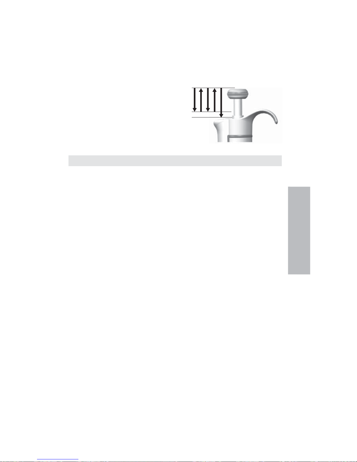
31
3. Distribuer le liquide prédéfi ni en appuyant doucement sur le bouton jusqu’au premier cran.
Maintenir le bouton au premier cran. Une partie du liquide doit rester dans le cône et ne sera
pas distribuée.
4. Continuer le pipetage en répétant les étapes 3 et 4.
Pipetage des échantillons hétérogènes
(ex.: déprotéinisation du sang pour dosage de glucose).
Suivre les étapes 1 et 2 de la méthode directe pour prélever l’échantillon de sang.
Essuyer soigneusement le cône à l’aide d’un mouchoir en papier propre et sec.
1. Plonger le cône dans le réactif et appuyer sur le
bouton jusqu’au premier cran, en s’assurant que la
pointe est bien dans le liquide.
2. Relâcher lentement le bouton jusqu’à sa position
de repos.
Le cône se remplira. Ne pas sortir le cône de
la solution.
3. Appuyer sur le bouton jusqu’au premier cran puis
le relâcher lentement. Répéter cette opération
jusqu’à ce que l’intérieur du cône soit propre.
4. Enfi n, appuyer sur le bouton jusqu’au deuxième cran pour vider complètement le cône.
Calibrage
Toutes les Finnpipette sont réglées et calibrées en usine avec de l’eau distillée ou déionisée,
selon la méthode de pipetage direct. Les pipettes sont conçues de sorte à pouvoir utiliser des
liquides de différentes températures et viscosités.
Matériel et conditions de test
Utiliser une balance analytique. Les spécifi cations de la balance doivent être choisies en
fonction du volume contrôlé de la pipette:
Volumes Sensibilité de la balance
inférieurs à 10μl 0,001 mg
10-100 μl 0,01 mg
supérieurs à 100μl 0,1 mg
Liquide test: eau distillée ou déionisée, grade 3, conforme à la norme ISO 3696. Les tests
doivent être effectués dans une pièce climatisée avec une température d’eau, de pipette et d’air
constante (±0,5°C) située entre 20°C et 25°C. L’humidité relative doit être supérieure à 50%.
Pour les volumes inférieurs à 50μl en particulier, l’humidité de l’air doit être la plus élevée
possible pour réduire la perte par évaporation. Des accessoires spécifi ques, tels qu’un piège à
évaporation, sont recommandés.
Procédure de vérifi cation du calibrage
La pipette est vérifi ée au volume maximum (volume nominal) et au volume minimum. Chaque
nouveau cône est d’abord pré-humidifi é 3 à 5 fois, et une série de dix pipetages est réalisée pour
chacun des deux volumes. Une pipette est toujours réglée pour distribuer le volume sélectionné.
L’utilisation de la méthode de pipetage directe est recommandée. Les erreurs tolérables
maximales sont fournies pour la méthode de pipetage directe.
Il est conseillé d’étalonner tous
les canaux des pipettes multicanaux, cependant une méthode acceptable consiste à étalonner
seuls les canaux des extrémités. L’ajustage se réalise alors sur un canal central. Il est également
recommandé d’utiliser les erreurs maximales tolérées défi nies par la norme ISO 8655, voir tableau
ci-dessous ou des spécifi cations propres à chaque utilisateur.
Procédure:
1. Effectuer 10 pipetages au volume minimum.
2. Effectuer 10 pipetages au volume maximum.
3. Calculer la justesse (E) et la répétabilité (cv) des deux séries.
4. Comparer les résultats aux tolérances.
Si les résultats calculés se trouvent dans les limites de tolérance sélectionnées, c’est que le
réglage de la pipette est correct.
Français
1 2 3 4 5
Page 32

32
Spécifi cations d’étalonnage ISO 8655
Spécifi cationsThermo Scientifi c Finnpipette F1 selon la norme ISO 8655.
Finnpipette F1 monocanal à volume variable
Gamme Volumes Erreur de justesse Erreur de répétabilité
μl μl % s.d. μl cv%
0,2-2 μl 2 ±0.080 ±4 0.040 2.0
0.2 ±0.080 ±40 0.040 20.0
0,5-5 μl 5 ±0.125 ±2.5 0.075 1.5
0.5 ±0.125 ±25 0.075 15
1-10 μl 10 ±0.120 ±1.2 0.080 0.8
1 ±0.120 ±12 0.080 8.0
2-20 μl 20 ±0.20 ±1.0 0.10 0.5
2 ±0.20 ±10.0 0.10 5.0
5-50 μl 50 ±0.50 ±1.0 0.20 0.4
5 ±0.50 ±10 0.20 4.0
10-100 μl 100 ±0.80 ±0.8 0.30 0.3
10 ±0.80 ±8.0 0.30 3.0
20-200 μl 200 ±1.60 ±0.8 0.60 0.3
20 ±1.60 ±8.0 0.60 3.0
30-300 μl 300 ±4.0 ±1.3 1.5 0.5
30 ±4.0 ±13 1.5 5.0
100-1000 μl 1000 ±8.0 ±0.8 3.0 0.3
100 ±8.0 ±8.0 3.0 3.0
0,5-5 ml 5000 ±40.0 ±0.8 15.0 0.3
500 ±40.0 ±8.0 15.0 3.0
1-10 ml 10000 ±60.0 ±0.6 30.0 0.3
1000 ±60.0 ±6.0 30.0 3.0
Finnpipette F1 monocanal à volume fi xe
Fixed Volume Erreur de justesse Erreur de répétabilité
μl μl % s.d.μl cv%
10 ±0.120 ±1.20 0.080 0.80
20 ±0.20 ±1.00 0.10 0.50
25 ±0.50 ±2.00 0.20 0.80
50 ±0.50 ±1.00 0.20 0.40
100 ±0.80 ±0.80 0.30 0.30
200 ±1.60 ±0.80 0.60 0.30
250 ±4.00 ±1.60 1.50 0.60
500 ±4.00 ±0.80 1.50 0.30
1000 ±8.00 ±0.80 3.00 0.30
2000 ±16.0 ±0.80 6.00 0.30
3000 ±40.0 ±1.33 15.00 0.50
5000 ±40.0 ±0.80 15.00 0.30
10000 ±60.0 ±0.60 30.00 0.30
Finnpipette F1 multicanaux à volume variable
Gamme Conduit Volumes Erreur de justesse Erreur de répétabilité
μl μl % s.d.μl cv%
1-10 μl 8, 12, 16 10 ±0.24 ±2.4 0.16 1.6
1 ±0.24 ±24 0.16 16
5-50 μl 8, 12, 16 50 ±1.0 ±2.0 0.4 0.8
5 ±1.0 ±20 0.4 8.0
10-100 μl 8, 12 100 ±0.80 ±0.8 0.30 0.3
10 ±0.80 ±8.0 0.30 3.0
30-300 μl 8, 12 300 ±8.0 ±2.7 3.0 1.0
30 ±8.0 ±26.7 3.0 10.0
Français
Page 33

33
Spécifi cations d’usine
Finnpipette F1 monocanal à volume variable
Erreur de Pointes utilisées
Gamme Volumes Erreur de justesse répétabilité par le
μl μl % s.d. μl cv% constructeur
0.2-2 μl 2 ±0,050 ±2,50 0,040 2,00 Flex 10
0,2 ±0,024 ±12,00 0,020 10,00
0.5-5 μl 5 ±0,075 ±1,50 0,050 1,00 Flex 10
0,5 ±0,030 ±6,00 0,025 5,00
1-10 μl, micro 10 ±0,100 ±1,00 0,050 0,50 Flex 10
1 ±0,025 ±2,50 0,020 2,00
1-10 μl 10 ±0,100 ±1,00 0,080 0,80 Flex 200
1 ±0,035 ±3,50 0,030 3,00
2-20 μl, micro 20 ±0,20 ±1,00 0,08 0,40 50
2 ±0,06 ±3,00 0,05 2,50
2-20 μl 20 ±0,20 ±1,00 0,08 0,40 Flex 200
2 ±0,06 ±3,00 0,05 2,50
5-50 μl, micro 50 ±0,30 ±0,60 0,15 0,30 50
5 ±0,15 ±3,00 0,125 2,50
5-50 μl 50 ±0,30 ±0,60 0,15 0,30 Flex 200
5 ±0,15 ±3,00 0,125 2,50
10-100 μl 100 ±0,80 ±0,80 0,20 0,20 Flex 200
10 ±0,30 ±3,00 0,10 1,00
20-200 μl 200 ±1,2 ±0,60 0,4 0,20 Flex 200
20 ±0,36 ±1,80 0,14 0,70
30-300 μl 300 ±1,8 ±0,60 0,6 0,20 Flex 300
30 ±0,45 ±1,50 0,18 0,60
100-1000 μl 1000 ±6,0 ±0,60 2,0 0,20 Flex 1000
100 ±1,0 ±1,00 0,6 0,60
0,5-5 ml 5000 ±25,0 ±0,50 10,0 0,20 5 ml
500 ±10,0 ±2,00 4,0 0,80
1-10 ml 10000 ±50,0 ±0,50 20,0 0,20 10 ml
1000 ±20,0 ±2,00 8,0 0,80
Finnpipette F1 monocanal à volume fi xe
Erreur de
Pointes utilisées
Fixed Volume Erreur de justesse
répétabilité
par le
μl μl % s.d. μl cv% constructeur
10 ±0,090 ±0,90 0,080 0,80 Flex 200
20 ±0,14 ±0,70 0,10 0,50 Flex 200
25 ±0,15 ±0,60 0,125 0,50 Flex 200
50 ±0,30 ±0,60 0,20 0,40 Flex 200
100 ±0,40 ±0,40 0,30 0,30 Flex 200
200 ±0,80 ±0,40 0,60 0,30 Flex 200
250 ±1,0 ±0,40 0,75 0,30 Flex 1000
500 ±1,5 ±0,30 1,5 0,30 Flex 1000
1000 ±3,0 ±0,30 3,0 0,30 Flex 1000
2000 ±6,0 ±0,30 4,0 0,20 5 ml
3000 ±9,0 ±0,30 6,0 0,20 5 ml
4000 ±12,0 ±0,30 8,0 0,20 5 ml
5000 ±15,0 ±0,30 10,0 0,20 5 ml
10000 ±30,0 ±0,30 20,0 0,20 10 ml
Français
Page 34

34
Finnpipette F1 multicanaux à volume variable
Erreur de
Erreur de
Pointes utilisées
Gamme Conduit Volumes
justesse
répétabilité
par le
μl μl % s.d. μl cv% constructeur
1.0-10 μl 8, 12, 16 10 ±0,240 ±2,40 0,160 1,60 Flex 10
1 ±0,120 ±12,00 0,080 8,00
5-50 μl 8, 12, 16 50 ±0,75 ±1,50 0,35 0,70 Flex 200
5 ±0,25 ±5,00 0,10 2,00
10-100 μl 8, 12 100 ±1,30 ±1,30 0,50 0,50 Flex 200
10 ±0,50 ±5,00 0,20 2,00
30-300 μl 8, 12 300 ±3,0 ±1,00 0,9 0,30 Flex 300
30 ±1,5 ±5,00 0,6 2,00
Réglage
Le réglage est effectué uniquement pour un volume. Réglage recommandé : volume minimal
ou bien 10 % du volume maximal. Les pipettes multicanaux sont ajustées sur un canal central.
1. Placer la clé dans les crans de la bague de calibrage
située au-dessous du bouton-poussoir.
2. Tourner la clé dans le sens des aiguilles d’une montre
pour augmenter le volume ou dans le sens contraire
pour le diminuer.
3. Une fois le réglage terminé, vérifi er à nouveau le
calibrage en suivant les instructions données ci-dessus.
Calculs
Conversion des poids en volume
V = (w + e) x Z V = volume (μl)
w = poids (mg)
e = perte par évaporation (mg)
Z = facteur de conversion pour μl/mg
La perte par évaporation peut être importante avec les micro-volumes. Pour déterminer la
perte de masse, verser de l’eau dans un bécher ou une fi ole, noter le poids et déclencher un
chronomètre. Noter le poids indiqué au bout de 30 secondes (ex. 6mg = 0,2mg/s).
Comparer ce résultat avec le temps de pipetage entre le tarage et la lecture du poids. Dans cet
exemple, le temps de pipetage devrait être de 10 secondes et la perte de masse serait donc de
2mg (10s x 0,2mg/s). En utilisant un piège à évaporation ou un couvercle sur bécher ou la fi ole,
l’erreur due à l’évaporation est négligeable et n’est donc pas prise en compte.
Le facteur Z permet de convertir le poids de l’eau en volume, à la température et à la pression de
contrôle. Z est égal à 1,0032μl/mg à 22°C et 95kPa. Se référer à la table de conversion page 62.
Erreur de justesse (erreur systématique)
La erreur de justesse correspond à la différence entre les volumes distribué et le volume
sélectionné de la pipette.
E = V - V0 E = erreur de justesse
V = volume moyen
V
0
= volume nominal
La erreur de justesse peut être exprimée en valeur relative: E% = 100% x E / V
0
Erreur de répétabilité (erreur aléatoire)
Erreur de répétabilité des pipetages est exprimée par la déviation standard (s) ou le coeffi cient
de variation (cv).
s = déviation standard
v = volume moyen
n = nombre de mesures
La déviation standard peut être exprimé en valeur relative (CV): CV = 100% x S / V
Français
+
Page 35

35
Entretien
Lorsque la Finnpipette F1 n’est pas utilisée, s’assurer qu’elle est rangée en position verticale.
Utiliser un portoir Finnpipette.
Le signe # fait référence aux photos qui commencent à la page 63.
Entretien à court terme
Il est recommandé de vérifi er avant chaque utilisation la propreté extérieure de la pipette.
Une attention toute particulière doit être accordée à l’embase porte-cône. Pour le nettoyage,
utiliser uniquement une solution d’éthanol à 70 %.
Entretien à long terme, pipettes simple conduit
Si la pipette est utilisée quotidiennement, elle doit être vérifi ée tous les trois mois. La procédure
d’entretien implique le démontage de la pipette.
Pipettes 1-1 000 μl
1. Appuyer sur l’éjecteur de cône.
2. Faire tourner l’éjecteur de cône 11 dans le sens inverse des aiguilles
d’une montre et tirer dessus pour l’extraire.
3. Tourner l’embase porte-cône dans le sens inverse des aiguilles d’une
montre à l’aide de la clé de calibrage.
4. Tirer sur le piston et les autres pièces. Appuyer avec le piston sur le reste
de l’ensemble du piston. Ensuite, tourner l’embase porte-cône à l’envers
et tarauder toutes les pièces depuis l’embase porte-cône. Ne pas oublier de
conserver toutes les pièces dans l’ordre sur la table en vue du remontage.
5. Nettoyer le piston, le ressort de piston et le joint torique avec un chiffon
sec non pelucheux.
6. Appuyer sur l’embase porte-cône pour retirer les saletés.
7. Graisser les parties nettoyées à l’aide du lubrifi ant fourni avec la pipette.
8. Remonter les composants de la pipette.
0,2-2 ul, 0,5-5 ul et 1-10 μl : Commencer par faire glisser le
ressort 22, le support du joint torique 23 et le joint torique 24
sur le tube 21. Avec le modèle 0,2-2ul, insérer le tube 27
dans le tube 21. Puis, faire à nouveau glisser le ressort 13, le
support du ressort 16 et les tubes 17 et 18, le grand joint
torique 19 et le petit joint torique 20 sur le piston.
Comprimer le ressort avec les doigts en appuyant
le piston sur le support du ressort 16 et faire
glisser le tube 21 avec le reste des pièces sur le
piston. Maintenir le ressort comprimé et faire
glisser avec précaution l’ensemble complet dans
l’embase porte-cône, puis relâcher le ressort.
2-20 μl et 5-50 μl : Faire de nouveau glisser le
ressort 13, le support du ressort 16 et les tubes 17
et 18, le grand joint torique 19 et le petit joint
torique 20 sur le piston. Comprimer le ressort avec
les doigts en appuyant le piston sur le support
du ressort 16 et faire glisser le grand joint torique
19, le petit joint torique 20, le support du ressort
21 et le ressort 22 (le petit diamètre contre le
support du ressort 21) sur le piston. Maintenir
le ressort comprimé et faire glisser avec
précaution l’ensemble complet dans l’embase
porte-cône, puis relâcher le ressort.
10-100 μl et 20-200 μl : Faire de nouveau glisser le ressort 13, le support du ressort 16 et le
joint torique 17 sur le piston. Faire glisser l’ensemble complet dans l’embase porte-cône.
100-1000 μl : Placer le joint torique 17 et la bague presse-joint 16 sur l’embase porte-cône.
Faire glisser le ressort 13 sur le piston, puis l’ensemble complet dans l’embase porte-cône.
9. Tous : Placer le ressort 15 et le support 14 en haut de l’embase porte-cône, puis insérer
avec précaution l’ensemble de l’embase porte-cône sur la poignée. Fixer l’embase porte cône en commençant par la faire tourner à la main dans le sens des aiguilles d’une montre
et en fi nissant de serrer avec la clé de calibrage.
10. Remonter l’éjecteur de cône.
Français
1
3
2
1000μl
2-300μl
Page 36

36
Pipette 0,5-5 ml et 1-10 ml
1. Appuyer sur l’éjecteur de cône.
2. Pour ouvrir l’éjecteur de cône 10, le tourner dans le
sensinverse des aiguilles d’une montre.
3. Démonter la partie inférieure de
l’éjecteur de cône 14 (clips de fi xation).
4. Tourner le cylindre 13 dans le sens
inverse des aiguilles d’une montre et
tirer sur l’ensemble de l’embase
porte-cône pour l’extraire.
5. Déposer le cylindre 13 en appuyant sur
les clips de fi xation du cylindre.
5. Nettoyer et graisser à nouveau le joint torique 12 et
le cylindre 13.
6. Assembler les pièces dans l’ordre inverse du démontage.
Entretien à long terme, pipettes multi-conduit
Dans le cas d’une utilisation quotidienne, la pipette doit être vérifi ée et
lubrifi ée tous les trois mois.
1. Placer la tête de la clé de calibrage #1 entre la bague 15 et l’éjecteur 23. Appuyer sur
l’outil jusqu’à ce que les pièces s’enclenchent les unes aux autres.
2. Vérifi er que le levier de l’éjecteur est en position haute et appuyer sur la partie de
l’éjecteur de cône du module.
Placer la tête de la clé de calibrage #2 dans le trou du tube de l’adaptateur 46.
3. Ouvrir légèrement l’extrémité supérieure de l’éjecteur de cône et retirer l’éjecteur de cône.
4. Dévisser le module de la poignée.
5. Retirer la barre du clip 22.
6. Appuyer sur le ressort 13 et enlever les pièces de blocage 12 de la rainure. Enlever le
ressort 13.
7. Relever les rebords courbés de verrouillage 44 et 45 et tirer sur les tubes 46 et 43
de l’adaptateur.
8. A l’aide d’un tournevis, retirer les quatre vis 20, 21 du couvercle du module et soulever
le couvercle.
9. Retirer la barre du piston 16 puis nettoyer les pistons 31 et les porte-cônes 42 avec un
chiffon sec non pelucheux.
10. Au besoin, procéder à l’entretien des porte-cônes :
16 conduits 1-10ul : Il n’est pas possible d’effectuer l’entretien des porte-cônes.
Les remplacer au besoin.
30-300 μl, 10-100 μl et 5-50 μl : Ouvrir le porte-cône en libérant doucement l’anneau du
couvercle 32 de son ergot de fi xation à l’aide du tournevis. Enlever toutes les pièces de
l’embase porte-cône. Nettoyer toutes les pièces. Au besoin, remplacer les joints toriques.
Prendre un piston. Faire glisser le ressort 33, la bague du couvercle 32 (grand trou), le
ressort 34, la bague presse-joint 35, (le joint torique 37 est plus gros pour le modèle
5-50μl/10-100μl) et le joint torique 36 (plus petit) sur le piston. Graisser le joint torique avec
la graisse silicone fournie dans l’emballage de la pipette. Faire glisser toutes les pièces dans
l’embase porte-cône 30 et fermer l’ergot de fi xation de l’anneau de couvercle 32.
1-10 μl : Ouvrir l’embase porte-cône en libérant doucement l’anneau du couvercle 32 de
son ergot de fi xation à l’aide du tournevis. Enlever toutes les pièces de l’embase
porte-cône. Nettoyer toutes les pièces. Au besoin, remplacer les joints toriques. Prendre un
piston. Faire glisser le ressort 33, l’anneau du couvercle 32 (grand trou), le support 35, le
joint torique 36 (grand), le joint torique 37(petit) et le support de joint torique 38 sur le
piston. Enfi ler ensuite le ressort 39, la bague presse-joint 40 (bords fi ns en premier) et le
joint torique 41 sur le porte-joint torique 38. Graisser les joints toriques avec le lubrifi ant
contenu dans l’emballage de la pipette. Faire glisser toutes les pièces dans l’embase
porte-cône 30 et fermer l’ergot de fi xation de l’anneau de couvercle 32.
11. Monter la barre du piston avec les pistons et les embases dans le couvercle. Placez les
goujons d’alignement du même côté pour monter le module. Fermer le couvercle en
resserrant les quatre vis. Insérer le clip 22.
12. Placer les tubes 46 et 43 de l’adaptateur sur le col du module et insérer les rebords
courbés de verrouillage 44 et 45.
13. Insérer le ressort 13 et les pièces de verrouillage 12 sur la tige de piston 16.
Français
1
2
3
Page 37

37
Problème
Fuite
Volume incorrect
Volume
incorrect
avec certains
liquides
Bouton de
distribution
bloqué en position
semi abaissée
Cause probable
Cône mal emboîté
Poussières ou cristaux entre le cône
et l’embase
Piston, joint torique et cylindre
encrassés
Cylindre et joint torique
insuffi samment lubrifi és
Joint torique endommagé
Utilisation incorrecte
Cône mal emboîté
Embase porte-cône (monocanal) ou
module (multicanaux) desserré
Calibrage modifi é: causé par une
mauvaise utilisation par exemple
Calibrage inadapté.
Les liquides très visqueux peuvent
demander un recalibrage.
En réglant le volume d’une seul
main, une pression unilatérale a été
appliquée sur le bouton-poussoir.
Solution
Bien vérifi er la mise en place
du cône
Nettoyer l’embase et remettre
un nouveau cône
Nettoyer et graisser le joint
torique et le cylindre.
Graisser en conséquence
Remplacer le joint torique
Suivre attentivement les
instructions
Bien vérifi er la mise en place
du cône
Serrer l’embase porte-cône ou le
module à l’aide de la clé de calibrage.
Recalibrer en respectant les
instructions
Recalibrer en fonction du
liquide utilisé.
Retirer le bouton vers le haut et
appuyer à nouveau jusqu’à la
position verrouillée
Français
14. Placer l’éjecteur de cône sur le module.
15. Visser le module dans la poignée et le serrer avec la tête de la clé de calibrage #2.
16. Appuyer sur le levier de l’éjecteur de cône jusqu’à émission d’un déclic.
Instructions d’entretien des embouts pour pipettes multicanaux
Pour assurer des performances régulières entre les canaux d’une pipette multicanaux, tous les
embouts doivent être changés en même temps lorsque vous devez changer l’un d’entre eux. Ne
mélangez jamais les embouts de différents sachets, car chaque sachet contient un ensemble
d’embouts assortis. Placez les goujons d’alignement du même côté pour monter le module. Se
référer à l’illustration en page 71.
Stérilisation
L’embase porte-cône d’une pipette monocanal peut être autoclavée plusieurs fois à 121°C
(252°F) (2 ata) pendant 20 minutes. Toutes les autres pièces des pipettes multicanaux ne sont
pas autoclavables. Une fois l’autoclavage terminé, l’embase porte-cône doit être refroidie à la
température ambiante pendant au moins deux heures. Avant d’utiliser la pipette, assurez-vous
que l’embase porte-cône est sèche. Nous vous recommandons de vérifi er le calibrage après
chaque cycle de stérilisation.
Pièces autoclavables :
Pièce numéro 42 : embase porte-cône monocanal
À l’exclusion des pièces numéro 10 et 14 pour les modèles de 0,5-5 ml et de 1-10 ml
Les numéros de pièce sont mentionnés dans la partie « Pièces détachées ».
En cas de probleme
Le tableau ci-dessous donne une liste des problèmes éventuels et des solutions à apporter.
ATTENTION!
Les Finnpipettes sont conçues pour permettre un entretien facile en laboratoire. Toutefois, si
vous préférez que nous ou notre représentant local se charge de l’entretien de vos pipettes,
assurez-vous que vous les avez décontaminées avant de nous les envoyer.
Remarque: les services postaux de certains pays peuvent interdire ou restreindre l’envoi par
courrier de matériels contaminés.
Page 38

38
Descripción del producto
La Finnpipette F1 es una micropipeta ajustable progresivamente y de propósito general, para el
muestreo y la dispensación de volúmenes de líquido exactos.
Su funcionamiento se basa en el principio de desplazamiento de aire (es decir, en medio aéreo)
y utiliza puntas separables y desechables.
El volumen de dispensación seleccionado se muestra digitalmente en una ventana de lectura
que se encuentra en el mango.
Los catorce modelos distintos de las pipetas Finnpipette F1 permiten trabajar con volúmenes
diferentes, abarcando un rango de 0,2 μl a 10 ml.
Rango Código de
Nº de pedido volumétrico color Finntip
4641010N 0,2 μl a 2 μl rosa Flex 10, 10, 20, 50
4641020N 0,5 μl a 5 μl rosa Flex 10, 10, 20, 50
4641030N 1 μl a 10 μl rosa Flex 10, 10, 20, 50
4641040N 1 μl a 10 μl amarillo
Flex 200, 250 Univ., 200 Ext, 300, Flex 300
4641050N 2 μl a 20 μl
turquioise
50
4641060N 2 μl a 20 μl amarillo
Flex 200, 250 Univ., 200 Ext, 300, Flex 300
4641130N 5 μl a 50 μl
turquioise
50
4641140N 5 μl a 50 μl amarillo
Flex 200, 250 Univ., 200 Ext, 300, Flex 300
4641070N 10 μl a 100 μl amarillo
Flex 200, 250 Univ., 200 Ext, 300, Flex 300
4641080N 20 μl a 200 μl amarillo
Flex 200, 250 Univ., 200 Ext, 300, Flex 300
4641090N 30 μl a 300 μl naranja Flex 300, 300
4641100N 100 μl a 1000 μl azul Flex 1000, 1000, 1000 Ext
4641110N 0,5 ml a 5 ml green 5 ml
4641120N 1 ml a 10 ml red 10 ml, Flex 10 ml Ext
13 modelos distintos de las pipetas Finnpipette F1 de volumen fi jo permiten trabajar con
volúmenes diferentes, abarcando un rango de 1 μl a 10 ml.
Rango Código de
Nº de pedido volumétrico color Finntip
4651020N 10 μl azul oscuro Flex 200, 250 Univ., 200 Ext, 300, Flex 300
4651130N 20 μl azul oscuro Flex 200, 250 Univ., 200 Ext, 300, Flex 300
4651030N 25 μl azul oscuro Flex 200, 250 Univ., 200 Ext, 300, Flex 300
4651040N 50 μl azul oscuro Flex 200, 250 Univ., 200 Ext, 300, Flex 300
4651050N 100 μl azul oscuro Flex 200, 250 Univ., 200 Ext, 300, Flex 300
4651140N 200 μl azul oscuro Flex 200, 250 Univ., 200 Ext, 300, Flex 300
4651060N 250 μl azul oscuro Flex 1000, 1000, 1000 Ext
4651070N 500 μl azul oscuro Flex 1000, 1000, 1000 Ext
4651080N 1000 μl azul oscuro Flex 1000, 1000, 1000 Ext
4651090N 2000 μl azul oscuro 5 ml
4651100N 3000 μl azul oscuro 5 ml
4651110N 5000 μl azul oscuro 5 ml
4651120N 10000 μl azul oscuro 10 ml, Flex 10 ml Ext
Los diez modelos de pipetas Finnpipette F1 Multicanal permiten trabajar con volúmenes
diferentes, abarcando un rango de 1 μl a 300 μl.
Nº de
Rango
Código de
pedido
Canal
volumétrico color
Finntip
4661000N 8 1 μl a 10 μl rosa Flex 10, 10, 20, 50
4661010N 8 5 μl a 50 μl amarillo
Flex 200, 250 Univ., 200 Ext, 300, Flex 300
4661020N 8 10 μl a 100 μl amarillo
Flex 200, 250 Univ., 200 Ext, 300, Flex 300
4661030N 8 30 μl a 300 μl naranja Flex 300, 300
4661040N 12 1 μl a 10 μl rosa Flex 10, 10, 20, 50
4661050N 12 5 μl a 50 μl amarillo
Flex 200, 250 Univ., 200 Ext, 300, Flex 300
4661060N 12 10 μl a 100 μl amarillo
Flex 200, 250 Univ., 200 Ext, 300, Flex 300
4661070N 12 30 μl a 300 μl naranja Flex 300, 300
4661080N 16 1 μl a 10 μl púrpura 20
4661090N 16 5 μl a 50 μl
turquioise
50
Español
Page 39

39
Pantalla digital
El volumen de dispensación seleccionado aparece claramente
indicado en la pantalla digital de gran tamaño que se encuentra
en el mango.
Materiales
La Finnpipette F1 está fabricada con materiales mecánicamente duraderos y químicamente
resistentes.
Para obtener instrucciones para la eliminación de residuos, póngase en contacto con las
autoridades locales de medio ambiente.
Para más información, póngase en contacto con
nosotros en
info.pipettes@thermofi sher.com.
Descripción de las puntas
Se recomienda el uso de puntas Finntip con las pipetas Finnpipette F1.
Las puntas Finntip se fabrican con polipropileno virgen de color natural que, por regla general,
se considera el único material sin contaminar apropiado para las puntas. Asimismo, las Finntip
se pueden introducir en el autoclave (121 °C).
Paquete
La pipeta Finnpipette F1 se suministra en un paquete de diseño especial que incluye los
siguientes elementos:
1. Pipeta Finnpipette
2. Herramienta de servicio
3. Herramienta de servicio multicanal
4. Punta Finntip de muestra
5. Tubo de grasa (Nº de pedido 2206040)
6. Manual de instrucciones
7. Certifi cado de calibración / certifi cado de garantía
8. Colgador para estante (Nº de pedido 2206040)
Seguridad
Las precauciones aparecen marcadas con el símbolo .
Uso previsto
El uso previsto de este dispositivo consiste en transferir líquidos en el rango volumétrico de
0,2 μl a 10 ml.
La pipeta Finnpipette F1 y la punta Finntips han sido diseñadas como componente de un sistema
de análisis para un usuario fi nal, que es responsable de la validación del sistema para garantizar
unos resultados fi ables y seguros.
Daños para la salud
Siga los procedimientos generales de prevención de peligros y las instrucciones de
seguridad; por ejemplo, lleve prendas protectoras, protección ocular y guantes.
Para el uso y la eliminación de residuos de material peligroso (p. ej., radiactivo y
potencialmente infeccioso), siga las instrucciones de seguridad y las prácticas generales de
laboratorio.
Ni la pipeta ni las puntas están destinadas al uso in vivo. No utilice la pipeta para el pipeteo
de líquidos que se vayan a inyectar en un cuerpo humano.
No expulse la punta hacia ninguna persona.
La Finnpipette F1 debe ser utilizada por personal capacitado con las habilidades de laboratorio
necesarias. Es necesario leer las instrucciones de uso antes y durante el uso del dispositivo
(pipeta y punta). La pipeta F1 puede usarse entre los +4 y los +40 °C.
Español
Page 40

40
+
1
2
Español
Resultados de dispensación incorrectos
El rendimiento puede variar a causa de factores como:
a. Método de pipeteado (se recomienda la técnica directa de pipeteo)
b. Temperatura (aire, líquido, recipiente, pipeta y punta)
c. Presión
d. Humedad
e. Operador, p. ej., movimiento del pulgar, ángulo de pipeteado
f. Densidad del líquido, viscosidad y presión de vapor
g. Tipo de punta
Si el rendimiento del pipeteo es crítico para el resultado de una aplicación específi ca, el
resultado debe garantizarse con una prueba alternativa o, si no es posible, mediante
duplicación de la prueba. La posibilidad de una dispensación de volumen incorrecta durante
el pipeteo no puede mitigarse totalmente.
Para evitar una dispensación inexacta y/o fugas, verifi que que la punta esté encajada
correctamente en la pipeta.
Al girar el botón de ajuste de volumen, no sobrepase el rango volumétrico de la pipeta. De lo
contrario, la pipeta podría sufrir daños o el rendimiento de pipeteo podría verse afectado.
El rendimiento de pipeteo no puede garantizarse si la punta se reutiliza.
Seleccione sólo puntas y pipetas con una codifi cación de colores coincidente.
Eliminación de los materiales
Siga los procedimientos de su laboratorio y específi cos de su país para la eliminación de
residuos con riesgo biológico o radioactivo. Consulte las normas locales para la eliminación de
material infeccioso.
Advertencia Las puntas pueden ser potencialmente infecciosas. Deseche todas las puntas
desechables como residuos con riesgo biológico.
Advertencia Descontamine la pipeta antes de la eliminación.
Para obtener instrucciones para la eliminación de residuos, póngase en contacto con las
autoridades locales de medio ambiente.
Para más información, póngase en contacto con
nosotros en
info.pipettes@thermofi sher.com.
En cuanto a los materiales de embalaje y empaquetado originales, utilice sus servicios de
reciclaje habituales.
Para más información, póngase en contacto con su representante local de Thermo Fisher
Scientifi c.
Uso de la pipeta
Selección del volumen de dispensación
1. Determine el volumen de dispensación con el mando que se
encuentra en la parte superior de la pipeta. Tire del mando para
activar el ajuste de volumen.
2. Para aumentar el volumen de dispensación, gire el mando en el
sentido contrario a las agujas del reloj. Para disminuirlo, gírelo
en la dirección opuesta.
3. Asegúrese de que el volumen de dispensación deseado quede
fi jado correctamente.
4. No ajuste volúmenes que estén fuera del rango
volumétrico especifi cado para la pipeta.
Si fuerza el mando excesivamente para superar dicho rango, puede
atascar el mecanismo y, con el tiempo, estropear la pipeta.
5. Para bloquear el volumen, presione el mando hacia abajo.
Etiqueta identifi cativa
Puede usar la etiqueta identifi cativa para indicar la aplicación de la pipeta,
sus iniciales, la fecha de calibración, etc. Retire el módulo de la pipeta para
sustituir la etiqueta. Escriba en la etiqueta con un lápiz y deslice la etiqueta,
con su soporte, en su ranura.
Page 41

41
Español
Expulsión de la punta
Para evitar el riesgo de contaminación, cada pipeta viene equipada con un sistema
de expulsión de puntas. Para soltar la punta, dirija la pipeta a un contenedor para
residuos y presione el expulsor con el dedo pulgar.
Ajuste el apoyo para dedos
El apoyo para dedos puede ajustarse girándolo 60 grados en
ambos sentidos desde su posición central. Normalmente,
los usuarios diestros lo giran hacia la izquierda (en el
sentido contrario a las agujas del reloj) para obtener la
mejor posición posible para expulsar la punta con el pulgar.
Vea la imagen.
Técnicas de pipeteo
Presione y suelte el pulsador lentamente y de forma continua, especialmente
cuando trabaje con líquidos muy viscosos. Nunca suelte el pulsador de forma
brusca.
Asegúrese de que la punta se encuentra fi rmemente ajustada en el cono
portapuntas.
Compruebe que no haya partículas extrañas en la punta.
Antes de empezar, llene la punta con la sustancia que va a pipetear y vacíela,
repitiendo esta acción 2 ó 3 veces. Sostenga la pipeta en posición vertical mientras
se aspira el líquido. El agarre de la pipeta debe apoyarse en el dedo índice. Asegúrese de que las
puntas, la pipeta y la solución se encuentran a la misma temperatura.
Técnica directa
Llene un frasco de reactivos limpio con el líquido con el que va a trabajar.
1. Presione el mando hasta la primera posición.
2. Sumerja la punta aproximadamente 1 cm bajo la
superfi cie del líquido y suelte el mando
lentamente. Saque la punta, retirando el exceso
de líquido del borde del frasco de la dispensación
para eliminar el exceso de líquido.
3. Descargue el líquido presionando ligeramente
el mando hasta la primera posición. Transcurrido
aproximadamente un segundo, vuelva a presionar
el mando hasta la segunda posición para vaciar
la punta. Esta acción vaciará la punta.
4. Libere el mando para que vuelva a la posición inicial. Si es necesario, cambie la punta y
siga pipeteando.
Técnica inversa
Se recomienda esta técnica para el pipeteo de líquidos muy viscosos o con tendencia a formar
espuma fácilmente. Asimismo, resulta apropiada para el trabajo con volúmenes reducidos.
Llene un frasco de reactivos limpio con el líquido con el que va a trabajar.
1. Presione el mando completamente hasta la
segunda posición.
2. Sumerja la punta aproximadamente 1 cm bajo la
superfi cie del líquido y suelte el mando
lentamente. Mantenga el pulsador en este punto.
Saque la punta, retirando el exceso de líquido del
borde del frasco de la dispensación para eliminar
el exceso de líquido.
3. Descargue el volumen prefi jado presionando
ligeramente el mando hasta la primera posición
.
Mantenga el mando en este punto. El líquido que quede en la punta no debe incluirse en
la dispensación.
4. Deseche el líquido restante junto con la punta, o bien, devuélvalo al frasco.
1 2 3 4
1 2 3 4
Page 42

42
Técnica repetitiva
La técnica repetitiva ofrece un modo rápido y sencillo para la dispensación repetida del mismo
volumen. Llene un frasco de reactivos limpio con el líquido con el que va a trabajar.
1. Presione el mando completamente hasta la segunda posición.
2. Sumerja la punta aproximadamente 1 cm bajo la superfi cie del líquido y suelte el mando
lentamente. Mantenga el pulsador en este punto.
Saque la punta, retirando el exceso de líquido del
borde del frasco de la dispensación para eliminar
el exceso de líquido.
3. Descargue el volumen prefi jado presionando
ligeramente el mando hasta la primera posición.
Mantenga el mando en este punto. El líquido
que quede en la punta no debe incluirse en
la dispensación.
4. Repita los pasos 3 y 4 para seguir pipeteando.
Pipeteo de muestras heterogéneas
(desproteinización en una determinación de glucosa en sangre, por ejemplo)
Siga los pasos 1 y 2 de la técnica directa para llenar la punta de sangre.
Limpie cuidadosamente la punta con un pañuelito limpio y seco.
1. Sumerja la punta en el reactivo y presione el
mando hasta la primera posición. Compruebe que
la punta se encuentra debajo de la superfi cie.
2. Libere lentamente el mando para que vuelva a
la posición inicial.
Esto llenará la punta. Mantenga la punta
sumergida dentro de la solución.
3. Presione el mando hasta la primera posición y
suéltelo lentamente. Repita este proceso hasta
que la pared interior de la punta quede limpia.
4. Por último, presione el mando hasta la segunda posición para vaciar la punta
completamente.
Calibración y ajuste
Todas las pipetas Finnpipette se distribuyen ajustadas y calibradas de fábrica para trabajar
dentro de los volúmenes especifi cados con agua destilada o desionizada y con la técnica directa.
Recuerde que el uso de otras técnicas de pipeteo puede afectar al resultado de la calibración.
Las pipetas se diseñan para permitir el reajuste para otras técnicas de pipeteo u otros líquidos
con temperaturas y viscosidades diferentes.
Requisitos de los dispositivos y condiciones del ensayo
Debe utilizar una balanza de laboratorio. Determine el valor de sensibilidad de la escala de la
balanza en función del volumen de ensayo seleccionado de la pipeta:
Rango volumétrico Sensibilidad
Menos de 10 μl 0,001 mg
10-100 μl 0,01 mg
Más de 100 μl 0,1 mg
Líquido de ensayo: agua, destilada o desionizada, agua de “grado 3” conforme a la norma ISO
3696. Los ensayos se deben realizar en una habitación sin corrientes de aire, manteniendo
el agua, la pipeta y el aire a una temperatura constante (±0,5 °C) entre los 15 °C y 30 °C. La
humedad relativa debe ser superior al 50%. La humedad del aire, especialmente cuando se
trabaja con volúmenes inferiores a 50 μl, debe ser lo más elevada posible para reducir el efecto
de la pérdida por evaporación. Se recomienda el uso de accesorios especiales, tales como el
concentrador de evaporación.
Procedimiento de comprobación de la calibración
Se debe comprobar el volumen máximo (volumen nominal) y el volumen mínimo de la pipeta.
Humedezca de 3 a 5 veces una nueva punta antes de usarla y realice una serie de diez
repeticiones a cada volumen. Las pipetas se ajustan siempre para dispensar (Ex) el volumen
seleccionado.
Español
1 2 3 4
1 2 3 4 5
Page 43

43
Español
Se recomienda utilizar la técnica directa de pipeteo. El número máximo permitido de errores
se ha diseñado para la técnica directa.
Se recomienda calibrar todos los canales en las pipetas
multicanal, otro método también viable es calibrar sólo los canales externos. El ajuste se hace
usando uno de los canales centrales. Se recomienda usar los límites de calibración de la norma
ISO8655 que podemos observar en las siguientes tablas o usar especifi caciones defi nidas por el
usuario.
Procedimiento:
1. Realice 10 repeticiones al volumen mínimo.
2. Realice 10 repeticiones al volumen máximo.
3. Calcule la inexactitud (A) y la imprecisión (cv) de cada serie.
4. Compare los resultados con los límites.
Si los resultados calculados están dentro de los límites seleccionados, el ajuste de la pipeta
es correcto.
Especifi caciones de calibración según norma ISO 8655
La especifi cación para la Thermo Scientifi c Finnpipette F1 se corresponde con la norma ISO 8655.
Finnpipette F1 monocanal de volumen variable
Rango Volumen Inexactitud Imprecisión
μl μl % s.d. μl cv%
0,2-2 μl 2 ±0.080 ±4 0.040 2.0
0.2 ±0.080 ±40 0.040 20.0
0,5-5 μl 5 ±0.125 ±2.5 0.075 1.5
0.5 ±0.125 ±25 0.075 15
1-10 μl 10 ±0.120 ±1.2 0.080 0.8
1 ±0.120 ±12 0.080 8.0
2-20 μl 20 ±0.20 ±1.0 0.10 0.5
2 ±0.20 ±10.0 0.10 5.0
5-50 μl 50 ±0.50 ±1.0 0.20 0.4
5 ±0.50 ±10 0.20 4.0
10-100 μl 100 ±0.80 ±0.8 0.30 0.3
10 ±0.80 ±8.0 0.30 3.0
20-200 μl 200 ±1.60 ±0.8 0.60 0.3
20 ±1.60 ±8.0 0.60 3.0
30-300 μl 300 ±4.0 ±1.3 1.5 0.5
30 ±4.0 ±13 1.5 5.0
100-1000 μl 1000 ±8.0 ±0.8 3.0 0.3
100 ±8.0 ±8.0 3.0 3.0
0,5-5 ml 5000 ±40.0 ±0.8 15.0 0.3
500 ±40.0 ±8.0 15.0 3.0
1-10 ml 10000 ±60.0 ±0.6 30.0 0.3
1000 ±60.0 ±6.0 30.0 3.0
Finnpipette F1 monocanal de volumen fi jo
Fixed Volume Inexactitud Imprecisión
μl μl % s.d.μl cv%
10 ±0.120 ±1.20 0.080 0.80
20 ±0.20 ±1.00 0.10 0.50
25 ±0.50 ±2.00 0.20 0.80
50 ±0.50 ±1.00 0.20 0.40
100 ±0.80 ±0.80 0.30 0.30
200 ±1.60 ±0.80 0.60 0.30
250 ±4.00 ±1.60 1.50 0.60
500 ±4.00 ±0.80 1.50 0.30
1000 ±8.00 ±0.80 3.00 0.30
2000 ±16.0 ±0.80 6.00 0.30
3000 ±40.0 ±1.33 15.00 0.50
5000 ±40.0 ±0.80 15.00 0.30
10000 ±60.0 ±0.60 30.00 0.30
Page 44

44
Español
Finnpipette F1 multicanal de volumen variable
Rango Canal Volumen Inexactitud Imprecisión
μl μl % s.d.μl cv%
1-10 μl 8, 12, 16 10 ±0.24 ±2.4 0.16 1.6
1 ±0.24 ±24 0.16 16
5-50 μl 8, 12, 16 50 ±1.0 ±2.0 0.4 0.8
5 ±1.0 ±20 0.4 8.0
10-100 μl 8, 12 100 ±0.80 ±0.8 0.30 0.3
10 ±0.80 ±8.0 0.30 3.0
30-300 μl 8, 12 300 ±8.0 ±2.7 3.0 1.0
30 ±8.0 ±26.7 3.0 10.0
Límites de especifi cación del fabricante
Finnpipette F1 monocanal de volumen variable
Punta de
Range Volume Inaccuracy Imprecision calibración en
μl μl % s.d. μl cv% fábrica
0.2-2 μl 2 ±0,050 ±2,50 0,040 2,00 Flex 10
0,2 ±0,024 ±12,00 0,020 10,00
0.5-5 μl 5 ±0,075 ±1,50 0,050 1,00 Flex 10
0,5 ±0,030 ±6,00 0,025 5,00
1-10 μl, micro 10 ±0,100 ±1,00 0,050 0,50 Flex 10
1 ±0,025 ±2,50 0,020 2,00
1-10 μl 10 ±0,100 ±1,00 0,080 0,80 Flex 200
1 ±0,035 ±3,50 0,030 3,00
2-20 μl, micro 20 ±0,20 ±1,00 0,08 0,40 50
2 ±0,06 ±3,00 0,05 2,50
2-20 μl 20 ±0,20 ±1,00 0,08 0,40 Flex 200
2 ±0,06 ±3,00 0,05 2,50
5-50 μl, micro 50 ±0,30 ±0,60 0,15 0,30 50
5 ±0,15 ±3,00 0,125 2,50
5-50 μl 50 ±0,30 ±0,60 0,15 0,30 Flex 200
5 ±0,15 ±3,00 0,125 2,50
10-100 μl 100 ±0,80 ±0,80 0,20 0,20 Flex 200
10 ±0,30 ±3,00 0,10 1,00
20-200 μl 200 ±1,2 ±0,60 0,4 0,20 Flex 200
20 ±0,36 ±1,80 0,14 0,70
30-300 μl 300 ±1,8 ±0,60 0,6 0,20 Flex 300
30 ±0,45 ±1,50 0,18 0,60
100-1000 μl 1000 ±6,0 ±0,60 2,0 0,20 Flex 1000
100 ±1,0 ±1,00 0,6 0,60
0,5-5 ml 5000 ±25,0 ±0,50 10,0 0,20 5 ml
500 ±10,0 ±2,00 4,0 0,80
1-10 ml 10000 ±50,0 ±0,50 20,0 0,20 10 ml
1000 ±20,0 ±2,00 8,0 0,80
Page 45

45
Español
Finnpipette F1 monocanal de volumen fi jo
Punta de
Fixed Volume Inaccuracy Imprecision calibración en
μl μl % s.d. μl cv% fábrica
10 ±0,090 ±0,90 0,080 0,80 Flex 200
20 ±0,14 ±0,70 0,10 0,50 Flex 200
25 ±0,15 ±0,60 0,125 0,50 Flex 200
50 ±0,30 ±0,60 0,20 0,40 Flex 200
100 ±0,40 ±0,40 0,30 0,30 Flex 200
200 ±0,80 ±0,40 0,60 0,30 Flex 200
250 ±1,0 ±0,40 0,75 0,30 Flex 1000
500 ±1,5 ±0,30 1,5 0,30 Flex 1000
1000 ±3,0 ±0,30 3,0 0,30 Flex 1000
2000 ±6,0 ±0,30 4,0 0,20 5 ml
3000 ±9,0 ±0,30 6,0 0,20 5 ml
4000 ±12,0 ±0,30 8,0 0,20 5 ml
5000 ±15,0 ±0,30 10,0 0,20 5 ml
10000 ±30,0 ±0,30 20,0 0,20 10 ml
Finnpipette F1 multicanal de volumen variable
Punta de
Range Channels Volume Inaccuracy Imprecision
calibración en
μl μl % s.d. μl cv% fábrica
1.0-10 μl 8, 12, 16 10 ±0,240 ±2,40 0,160 1,60 Flex 10
1 ±0,120 ±12,00 0,080 8,00
5-50 μl 8, 12, 16 50 ±0,75 ±1,50 0,35 0,70 Flex 200
5 ±0,25 ±5,00 0,10 2,00
10-100 μl 8, 12 100 ±1,30 ±1,30 0,50 0,50 Flex 200
10 ±0,50 ±5,00 0,20 2,00
30-300 μl 8, 12 300 ±3,0 ±1,00 0,9 0,30 Flex 300
30 ±1,5 ±5,00 0,6 2,00
Ajuste
El ajuste se realiza sólo para un volumen. El volumen de ajuste recomendado es el volumen
mínimo o el 10% del volumen máximo. Las pipetas multicanales se ajustan usando uno de los
canales centrales.
1. Inserte la herramienta de servicio en las aberturas
de la tuerca de calibración que se encuentra en la
parte superior del mango.
2. Gire la herramienta de servicio en el sentido de
las agujas del reloj para aumentar el volumen o en
la dirección opuesta para disminuirlo.
3. Una vez ajustado el volumen, compruebe la
calibración siguiendo las instrucciones descritas
anteriormente.
Fórmulas para el cálculo de los
resultados
Conversión de masa a volumen
V = (w + e) x Z V = volumen (μl)
w = peso (mg.)
e = pérdida por evaporación (mg.)
Z = factor de conversión para la conversión μl/mg
La pérdida por evaporación puede ser un factor relevante cuando se trabaja con volúmenes
reducidos. Para determinar la pérdida de masa, llene de agua el recipiente a pesar, observe la
lectura obtenida y ponga en marcha un cronómetro. Compruebe cómo disminuyen los valores al
cabo de 30 segundos (p. ej., 6 mg = 0,2 mg/s).
+
Page 46
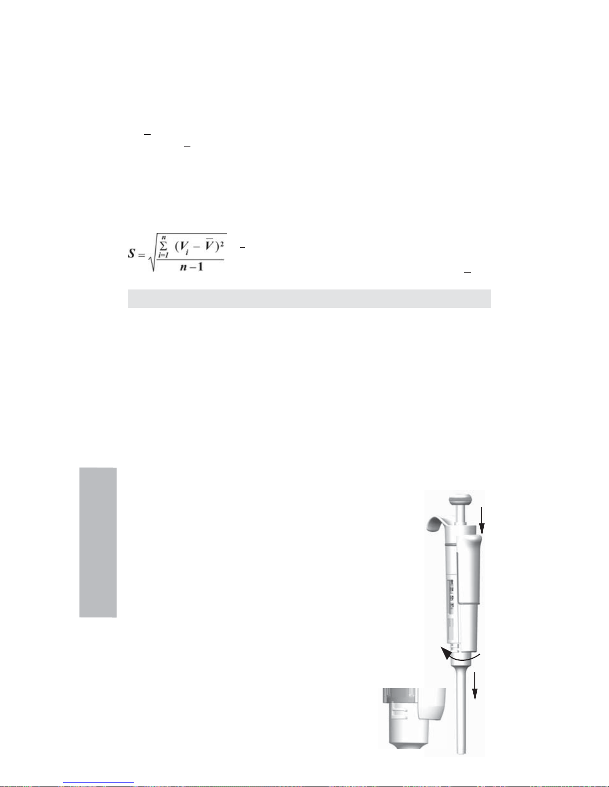
46
Compare esta lectura con el tiempo de pipeteo transcurrido entre la acción y la lectura.
Normalmente, el tiempo de pipeteo es de 10 segundos y la pérdida de masa de 2 mg (10 s x 0,2
mg/s) en este ejemplo. Si cubre el recipiente con un concentrador de evaporación o una tapa, no
es preciso por lo general que corrija la evaporación.
El factor Z se utiliza para convertir el peso del agua en volumen a una temperatura y presión
de ensayo. Un valor típico es 1,0032 μl/mg a 22 °C y 95 kPa. Consulte la tabla de conversiones
de la página 62.
Inexactitud (error sistemático)
La inexactitud es la diferencia entre el volumen dispensado y el volumen seleccionado de una pipeta.
A = V - V0 A = Inexactitud
V = Volumen medio
V
0
= Volumen nominal
La inexactitud se puede expresar como un valor relativo: A% = 100% x A / V
0
Imprecisión (error aleatorio)
La imprecisión hace referencia a la repetibilidad del pipeteo. Se expresa en forma de desviación
estándar (s) o como coefi ciente de variación (cv)
s = Desviación estándar
v = Volumen medio
n = Número de mediciones
La desviación estándar se puede expresar como un valor relativo (CV) CV = 100% x S / V
Mantenimiento
Guarde la pipeta Finnpipette F1 cuando no se utilice y asegúrese de que se encuentra en posición
vertical. Se recomienda para este propósito el uso del soporte especial para pipetas Finnpipette.
La referencia se refi ere a las vistas de detalle del principio de la página 63.
Mantenimiento a corto plazo
Compruebe al comienzo de cada día que no haya polvo ni suciedad en las superfi cies externas
de la pipeta.
Preste especial atención al cono portapuntas. Utilice exclusivamente etanol al 70% para limpiar
la pipeta (no utilice otro tipo de disolvente).
Mantenimiento a largo plazo, pipetas monocanal
Si la pipeta se utiliza diariamente, debe verifi carla cada tres meses. El servicio de mantenimiento
empieza por desmontar la pipeta.
Pipetas de 2-1.000 μl
1. Pulse el expulsor.
2. Gire el expulsor 11 en el sentido contrario a las agujas del reloj y tire de él
hacia fuera.
3. Gire hacia fuera el cono portapuntas en el sentido contrario a las agujas
del reloj con ayuda de la herramienta de servicio.
4. Tire del émbolo y las demás piezas hacia fuera. Presione hacia fuera el
émbolo con el resto del conjunto de émbolo. A continuación, invierta
el cono portapuntas y golpee suavemente todas las piezas para retirarlas
del cono portapuntas. Recuerde que debe conservar todas las piezas en
orden sobre la mesa, para el montaje posterior.
5. Limpie el émbolo, el muelle del émbolo y las juntas tóricas con un
paño seco sin hilos.
6. Compruebe que el cono portapuntas no contenga partículas extrañas.
7. Engrase las partes limpias con el lubricante que viene con la pipeta.
8. Vuelva a montar los componentes de la pipeta.
0,2-2 μl, 0,5-5 μl y 1-10 μl: Deslice primero el muelle 22, el soporte 23
para junta tórica y la junta tórica 24 en el tubo 21. En el modelo para
0,2-2 μl, inserte el tubo 27 en el tubo 21. A continuación,
deslice de nuevo en el émbolo el muelle 13, el soporte 16
para muelle y los tubos 17 y 18, la junta tórica mayor 19 y la
junta tórica menor 20.
Español
1
3
2
Page 47

47
Español
Comprima el muelle con los dedos presionando
el émbolo y el soporte 16 para muelle uno contra
otro y deslice el tubo 21 con el resto de las partes
del émbolo. Mantenga comprimido el muelle y
deslice cuidadosamente todo el conjunto hacia el
interior del cono portapuntas, liberando a
continuación el muelle.
2-20 μl y 5-50 μl: Deslice el muelle 13, el soporte
16 para muelle y los tubos 17 y 18, la junta tórica
mayor 19 y la junta tórica menor 20 de nuevo en el
émbolo. Comprima el muelle con los dedos
presionando el émbolo y el soporte 16 para muelle
uno contra otro y deslice la junta tórica mayor 19,
la junta tórica menor 20, el soporte 21 para muelle
y el muelle 22 (con el diámetro menos
apoyado contra el soporte 21 para muelle) en el
émbolo. Mantenga comprimido el muelle y deslice
cuidadosamente todo el conjunto hacia el interior
del cono portapuntas, liberando a continuación
el muelle.
10-100 μl y 20-200 μl: Deslice el muelle 13, el soporte 16 para muelle y la junta tórica 17 de
nuevo en el émbolo. Deslice todo el conjunto hacia el interior del cono portapuntas.
100-1.000 μl: Coloque la junta tórica 17 y el anillo de soporte 16 en el cono portapuntas.
Deslice el muelle 13 en el émbolo y deslice todo el conjunto en el cono portapuntas.
9. Todas: Coloque el muelle 15 y el soporte 14 en la parte superior del cono portapuntas 11 e
inserte cuidadosamente el conjunto de cono portapuntas en el mango. Fije el cono
portapuntas apretándolo primero a mano efectuando un giro hacia la derecha y luego realice
el ajuste defi nitivo con la herramienta de servicio.
10. Vuelva a montar el expulsor.
Pipetas de 0,5-5 ml y 1-10 ml
1. Pulse el expulsor.
2. Gire el expulsor 10 en el sentido
contrario a las agujas del reloj para
abrirlo.
3. Desmonte la parte inferior del
expulsor 14 (ajuste a presión).
4. Gire el cilindro 13 en el sentido
contrario a las agujas del
reloj y tire del conjunto de cono portapuntas hacia fuera.
5. Retire el cilindro 13 presionando los ajustes a presión
del cilindro.
5. Limpie y reengrase la junta tórica 12 y el cilindro 13.
6. Monte las piezas en el orden opuesto al del desmontaje.
Mantenimiento a largo plazo, pipetas multicanal
Si la pipeta se utiliza diariamente, debe verifi carla y lubricarla cada tres meses.
1. Coloque el cabezal nº 1 de la herramienta de servicio entre
el anillo 15 y el expulsor 23. Presione la herramienta hasta que las piezas
se separen con un chasquido.
2. Compruebe que la palanca del expulsor esté en posición vertical y tire
hacia abajo de la parte de expulsor de puntas del módulo.
Coloque el cabezal nº 2 de la herramienta de servicio en el orifi cio del tubo adaptador 46.
3. Abra levemente el extremo superior del expulsor de puntas y retire el expulsor de puntas.
4. Desatornille y retire el módulo del mango.
5. Retire la clip 22 hacia fuera.
6. Presione el muelle 13 y retire las piezas de bloqueo 12 de la ranura. Retire el muelle 13.
7. Retire las garras de bloqueo 44 y 45 y tire del tubo adaptador 46 y del tubo 43 hacia fuera.
8. Utilice un destornillador para retirar los cuatro tornillos 20,21 de la cubierta del módulo y
levante la cubierta para separarla.
1
2
3
1000μl
2-300μl
Page 48

48
9. Retire la barra 16 de los émbolos y limpie los émbolos 31 y los conos portapuntas 42 con
un paño seco sin hilas.
10. En caso necesario, mantenga los conos portapuntas:
16 canales y 1-10 μl: Los conos portapuntas no admiten mantenimiento. Sustitúyalos
en caso necesario.
30-300 μl, 10-100 μl y 5-50 μl: Abra con cuidado el cono portapuntas liberando el anillo
32 de la cubierta de su punto de unión por presión, con ayuda de un destornillador. Retire
todas las piezas del cono portapuntas. Limpie todas las piezas. En caso necesario,
sustituya las juntas tóricas. Tome un émbolo. Deslice el muelle 33, el anillo de cubierta 32
(orifi cio mayor), el muelle 34, el anillo de soporte 35, (junta tórica 37 mayor en 5-50 μl/
10-100μl) y la junta tórica 36 (menor) sobre el émbolo. Engrase la junta tórica con el
lubricante incluido con la pipeta. Deslice todas las piezas hacia el interior del cono
portapuntas 30 y cierre la unión por presión del anillo 32 de la cubierta.
1–10 μl: Abra con cuidado el cono portapuntas liberando el anillo 32 de la cubierta de su
punto de unión por presión, con ayuda de un destornillador. Retire todas las piezas del
cono portapuntas. Limpie todas las piezas. En caso necesario, sustituya las juntas tóricas.
Tome un émbolo. Deslice el muelle 33, el anillo de la cubierta 32 (orifi cio mayor), el apoyo
35, la junta tórica 36 (mayor), la junta tórica 37 (menor) y el apoyo de junta tórica 38 sobre
el émbolo. A continuación, deslice el muelle 39, el apoyo de muelle 40 (con los bordes
afi lados por delante) y la junta tórica 41 sobre el apoyo de junta tórica 38. Engrase las
juntas tóricas con el lubricante incluido con la pipeta. Deslice todas las piezas hacia el
interior del cono portapuntas 30 y cierre la unión por presión del anillo 32 de la cubierta.
11. Instale la barra de émbolos con los émbolos y conos portapuntas en la cubierta. Coloque los
pernos de alineación hacia el mismo lado cuando monte el módulo. Cierre la cubierta con los
cuatro tornillos. Inserte el clip 22.
12. Coloque el tubo adaptador 46 y el tubo 43 en el cuello del módulo e inserte las garras
de bloqueo 44 y 45.
13. Inserte el muelle 13 y las piezas de bloqueo 12 en el vástago de émbolo 16.
14. Coloque el expulsor de puntas en el módulo.
15. Atornille el módulo al mango y apriete con el cabezal nº 2 de la herramienta de servicio.
16. Presione hacia abajo la palanca del expulsor de puntas hasta que escuche un “clic”.
Instrucciones de servicio técnico para conos porta-puntas de
pipetas multicanal
Para garantizar un correcto funcionamiento de todos los canales de una pipeta multicanal, debe
reemplazar a la vez todos los conos porta-puntas siempre que deba reemplazar uno de ellos. No
combine conos porta-puntas de paquetes distintos, dado que cada bolsa contiene un conjunto
de conos porta-puntas que se corresponden exactamente. Coloque los pernos de alineación
hacia el mismo lado cuando monte el módulo. Consulte la imagen de la página 71.
Esterilización
El conjunto de cono portapuntas de una pipeta monocanal puede esterilizarse repetidas veces
en autoclave a 121°C
(252°F)
(2 ata) durante 20 minutos. No puede esterilizarse en autoclave
ninguna otra parte, ni las pipetas multicanales. Tras la esterilización en autoclave, el conjunto
de cono portapuntas debe dejarse enfriar a temperatura ambiente durante al menos dos
horas. Antes de pipetear, asegúrese de que el conjunto de cono portapuntas esté seco. Le
recomendamos que compruebe la calibración después de cada ciclo de esterilización.
Piezas esterilizables en autoclave:
Pieza número 42: conjunto de cono portapuntas monocanal
Excepto las piezas números 10 y 14 de los modelos de 0,5-5 ml y 1-10 ml
Los números de las piezas se indican en la sección Repuestos.
Español
Page 49

49
Defecto
Goteo
Dispensación
errónea
Dispensación
errónea con
determinados
líquidos
Botón de
dispensación
atascado en
posición
parcialmente
hacia abajo
Posible causa
Colocación incorrecta de la punta.
Presencia de partículas extrañas entre
la punta y el cono portapuntas.
Presencia de partículas extrañas entre
el émbolo, la junta tórica y el cilindro.
Cantidad insufi ciente de lubricante
en el cilindro y la junta tórica.
La junta tórica está dañada.
Manejo incorrecto.
Colocación incorrecta de la punta.
Cono portapuntas (monocanal) o
módulo (multicanal) suelto
Cambios en la calibración:
causados por un mal uso, por ejemplo,
una calibración inapropiada.
Puede que deba volver a calibrar la
pipeta para trabajar con líquidos
muy viscosos.
Se ha aplicado fuerza unilateral en el
botón al ajustar el volumen con una
mano
Solución
Coloque la punta fi rmemente.
Limpie los conos portapuntas y
coloque puntas nuevas.
Limpie y lubrique la junta tórica
y el cilindro.
Lubrique los componentes
correctamente.
Cambie la junta tórica.
Siga las instrucciones
atentamente.
Coloque la punta fi rmemente.
Apriete el cono portapuntas
o el módulo con ayuda de la
herramienta de servicio.
Vuelva a calibrar la pipeta
siguiendo las instrucciones.
Vuelva a calibrar la pipeta con
los líquidos con los que va a
trabajar.
Tire del botón hacia arriba y
vuelva a empujarlo hacia abajo
hasta la posición de bloqueo
ADVERTENCIA
El mantenimiento de la pipeta Finnpipette se puede llevar a cabo fácilmente en
el laboratorio. Si desea que nosotros o su representante local realicemos este
servicio, envíenos la pipeta, asegurándose de descontaminarla previamente.
Tenga en cuenta que las autoridades del servicio de correos de su país pueden
prohibir o limitar el envío de materiales contaminados.
Solución de problemas
En la tabla que aparece a continuación se describen varios problemas que pueden surgir y la
manera de solucionarlos.
Español
Page 50

50
製品について
フィンピペットF1は、液体の量を正確に採取して分注するための連続可変式汎用マイク
ロピペットです。フィンピペットF1は、空気置換(エアインターフェース)方式で動作
し、取り外し可能な使い捨てチップを採用しています。
分注容量は、ハンドルにあるディスプレイ(表示窓)に表示されます。
フィンピペットF1の シングルチャンネル ピペットには14種類のモデルがあり、0,2 µl
から10 mlまでの容量範囲に対応しています。
製品番号 容量範囲
カラーコード
フィンチップ
4641010N 0,2 µl to 2 µl ピンク フレックス10、10、20、50
4641020N 0,5 µl to 5 µl ピンク フレックス10、10、20、50
4641030N 1 µl to 10 µl ピンク フレックス10、10、20、50
4641040N 1 µl to 10 µl
イエロー フレックス200,250ユニバーサル,200Ext,300,フレックス300
4641050N 2 µl to 20 µl トルコ石 50
4641060N 2 µl to 20 µl
イエロー フレックス200,250ユニバーサル,200Ext,300,フレックス300
4641130N 5 µl to 50 µl トルコ石 50
4641140N 5 µl to 50 µl
イエロー フレックス200,250ユニバーサル,200Ext,300,フレックス300
4641070N 10 µl to 100 µl
イエロー フレックス200,250ユニバーサル,200Ext,300,フレックス300
4641080N 20 µl to 200 µl
イエロー フレックス200,250ユニバーサル,200Ext,300,フレックス300
4641090N 30 µl to 300 µl
オレンジ
フレックス300、300
4641100N 100 µl to 1000 µl ブルー フレックス1000、1000、1000 Ext
4641110N 0,5 ml to 5 ml
グリーン
5 ml
4641120N 1 ml to 10 ml
レッド
10 ml、 フレックス10 ml Ext
フィンピペットF1の容量固定ピペットには13種類のモデルがあり、1 µlから10 mlまでの
容量範囲に対応しています。
製品番号 容量範囲 カラーコード
フィンチップ
4651020N 10 µl
ダークブルー フレックス200,250ユニバーサル,200Ext,300,フレックス300
4651130N 20 µl
ダークブルー フレックス200,250ユニバーサル,200Ext,300,フレックス300
4651030N 25 µl
ダークブルー フレックス200,250ユニバーサル,200Ext,300,フレックス300
4651040N 50 µl
ダークブルー フレックス200,250ユニバーサル,200Ext,300,フレックス300
4651050N 100 µl
ダークブルー フレックス200,250ユニバーサル,200Ext,300,フレックス300
4651140N 200 µl
ダークブルー フレックス200,250ユニバーサル,200Ext,300,フレックス300
4651060N 250 µl ダークブルー フレックス1000、1000、1000 Ext
4651070N 500 µl ダークブルー フレックス1000、1000、1000 Ext
4651080N 1000 µl ダークブルー フレックス1000、1000、1000 Ext
4651090N 2000 µl
ダークブルー
5 ml
4651100N 3000 µl
ダークブルー
5 ml
4651110N 5000 µl
ダークブルー
5 ml
4651120N 10000 µl
ダークブルー
10 ml、フレックス10 ml Ext
フィンピペットF1のマルチチャンネルピペットには,次の10種類のモデルがあり,1µl
から300 µlまでの分注ができます。
チャン カラー
製品番号 ネル数 容量範囲 コード フィンチップ
4661000N 8 1 µl to 10 µl ピンク フレックス10、10、20、50
4661010N 8 5 µl to 50 µl
イエロー フレックス200,250ユニバーサル,200Ext,300,フレックス300
4661020N 8 10 µl to 100 µl
イエロー
フレックス200,250ユニバーサル,200Ext,300,フレックス300
4661030N 8 30 µl to 300 µl
オレンジ
フレックス300、300
4661040N 12 1 µl to 10 µl ピンク フレックス10、10、20、50
4661050N 12 5 µl to 50 µl
イエロー フレックス200,250ユニバーサル,200Ext,300,フレックス300
4661060N 12 10 µl to 100 µl
イエロー フレックス200,250ユニバーサル,200Ext,300,フレックス300
4661070N 12 30 µl to 300 µl
オレンジ
フレックス300、300
4661080N 16 1 µl to 10 µl パープル 20
4661090N 16 5 µl to 50 µl トルコ石 50
日
本
語
Page 51

51
日
本
語
ディスプレイ
設定した容量は、ハンドルにある大きなデジタルディス
プレイ(表示窓)にはっきり表示されます。
材質
フィンピペットF1は、耐摩耗性、耐薬品性に優れた材料
で製造されています。
廃棄物処理に関しては、各自治体の環境局にお問い合わせください。詳しくは、弊
社
(info.pipettes@thermofisher.com)までお問い合わせください。
チップ
フィンチップは、フィンピペットF1と組み合わせて使用することをお勧めします。
フィンチップは、コンタミネーションがなく、チップに適した唯一の材質とされる無
着色のポリプロピレン製です。また、フィンチップはオートクレーブ処理が可能です
(121°)。
パッケージ
Finnpipette F1 は、専用パッケージに入れてお届けします。パッケージ内容は以下の
とおりです:
1. Finnpipette F1
2. サービスツール
3. マルチチャンネルサービスツール
4. Finntip(サンプル)
5. チューブ入グリース(製品番号 2203130)
6. 取扱説明書
7. 検定証明書/保証書
8. シェルフハンガー(製品番号 2206040)
9. シール2枚
安全にお使いいただくために
注意事項はこのシンボルマークで表します。
使用目的
この製品の使用目的は、0,2 µlから10 mlまでの量の液体の移動です。
Finnpipette F1 ピペットとFinntipsチップは、信頼性と確実性のある結果を得るため
のシステムの検証に責任を有するエンドユーザー用に分析システムのコンポーネントと
して設計されています。
健康被害
防護服、保護眼鏡、手袋の着用など、危険防止と安全の指示に関する一般手順に従
ってください。
危険性(放射性および感染の可能性など)のある物質の使用と廃棄物処理について
は、安全に関する指示や一般の試験所基準に従ってください。
ピペットとチップはin vivoでの使用を意図していません。 ピペットは、ヒトの体内
に注入する液体のピペッティングに使用しないでください。
チップを他の人に向けて取り外さないでください。
Finnpipette F1 はラボにおいて必要なスキルを持ち、トレーニングを受けた方がご使用
ください。製品(ピペットとチップ)の使用前および使用中についての注意を必ずお読
みください。 F1ピペットは+4°C~+40°Cで使用できます。
不正確な分注結果
パフォーマンスは以下によって影響を受けることがあります。
a. ピペッティング方法(フォワード法をお勧めします)
b. 温度(空気、液体、容器、ピペット、チップ)
c. 気圧
d. 湿度
e. オペレータの個人差。例えば、親指の動き、ピペッティング角度
f. 液体濃度、粘性および蒸気圧
g. チップの種類
Page 52

52
ピペッティングパフォーマンスが特定のアプリケーションの結果に重要な影響を及
ぼす場合、結果を別な試験で検証するか、それができない場合はデュプリケート
をとって確認する必要があります。 ピペッティング中の分注容量が正確でない可能
性を、完全に排除することはできません。
不正確な分注またはリークを防ぐために、チップがピペットに適切に装着されてい
ることを確認してください。
容量設定ボタンを回すときは、ピペットの容量レンジを超えないでください。ピペ
ット
が損傷したり、ピペッティングパフォーマンスに影響を及ぼしたりすることが
あります。
チップを再使用した場合、ピペッティングパフォーマンスは保証できません。
カラーコードが一致するチップとピペットを選択してください。
材料の廃棄
バイオハザード廃棄物または放射性廃棄物の処分には、研究室と国で定められた手順に
従ってください。伝染性物質の廃棄に関する現地の規定を参照してください。
警告 先端は伝染性である場合があります。すべての使用済みの先端はバイオハザード
廃棄物として廃棄してください。
警告 廃棄前にピペットの汚染除去を行ってください。セクション を参照してださい。
廃棄物処理に関しては、各自治体の環境局にお問い合わせください。詳しくは、弊
社
(info.pipettes@thermofisher.com)までお問い合わせください。
元の梱包と梱包材に関しては、正規リサイクル業者を使ってください。
詳細情報は、最寄りのThermo Fisher Scientific代理店に連絡してください。
ピペットの操作
分注容量の設定
1. ピペットの上部にあるプッシュボタンを使って分注容量を
設定します。容量設定をするときは、プッシュボタンを引き
出します。
2. 分注容量を増やすには、プッシュボタンを 反時計回りに
回します。分注容量を減らすには、プッシュボタンを時計
回りに回します。
3. 設定したい分注容量がカチッと正しい位置にセットされた
ことを確認してください。
4. 分注容量は、ピペットの規格範囲を超えて設定しない
でください。
規格範囲外までプッシュボタンを無理に回そうとする
と、ピペットの故障や損傷の原因になることがあり
ます。
5. プッシュボタンを押し下げて容量をロックします。
IDタグ
IDタグにはピペットの用途、使用者のイニシャル、較正
日などを記入できます。タグを取り替えるにはピペット
のモジュールを取り外します。ラベルに鉛筆で必要事項
を記入し、タグをホルダーと一緒に元通りにスロットに
滑り込ませます。
チップイジェクション
コンタミネーション防止のため、各ピペットにチップイ
ジェクタシステムを装備しています。ピペットの先端を
廃棄容器に向け、親指でチップイジェクタを押すと、チ
ップに手を触れずに外すことができます。
フィンガーレストの調整
フィンガーレストは、中心位置からいずれの方向に
も60度まで回転します。右利きの人は通常、フィンガ
ーレストを左(反時計回り)に回すと、親指でチップ
イジェクションしやすい位置になります。図を参照し
てください。
日
本
語
+
1
2
Page 53

53
ピペッティングテクニック
プッシュボタンの操作は常にゆっくり行い、特に粘性の高い液体を扱うときは、ゆっく
りと押してゆっくりと離します。プッシュボタンをはじくような扱いは決してしないで
ください。
チップをチップコーンにしっかりと装着してください。
チップ内部に異物が入っていないことを確認してください。
分注を始める前に、分注する溶液を2、3回吸排します。溶液を吸引するときは、ピペッ
トを垂直に保ち、人差し指の上にフィンガーレストがかかるように握ってください。
チップ、ピペットおよび溶液が同じ温度であることを確認してください。
フォワード法
分注する溶液をきれいな容器(リザーバー)に入れます。
1 プッシュボタンを1段目まで押し下げます。
2. チップを分注液の液面から約1cm下まで浸し、
プッシュボタンをゆっくりと離します。チッ
プを溶液から引き上げ、容器の縁に先端を軽
く触れて外側についた余分な溶液を除
きます。
3. プッシュボタンを1段目まで静かに押し下げ、
溶液を分注します。約1秒後に、プッシュボタ
ンをさらに2段目まで押し下げます。この操作
により、チップの中が空になります。
4. プッシュボタンを離してレディポジションに
戻します。必要に応じてチップを交換し、ピペッティングを続けます。
リバース法
リバース法は、粘性の高い液体や泡立ちやすい溶液の分注に適しています。また、微量
分注にもお勧めします。分注する溶液をきれいな容器(リザーバー)に入れます。
1. プッシュボタンを2段目まで押し下げます。
2. チップを分注液の液面から約1cm下まで浸し、
プッシュボタンをゆっくりと離します。この
操作により、チップが溶液で満たされます。
チップを溶液から引き上げ、容器の縁に先端
を軽く触れさせて外側についた余分な溶液を
除きます。
3. プッシュボタンを1段目まで静かに押し下げ、
設定した容量の溶液を分注します。プッシュ
ボタンを1段目で止めます。チップの中に少
量の溶液が残りますが、これは分注しません。
4. チップ内に残った溶液を、廃棄するか元の容器に戻します。
リピート法
リピート法は、同じ溶液を同じ容量だけ、繰り返しすばやく分注するのに適していま
す。分注する溶液をきれいな容器(リザーバー)に入れます。
1. プッシュボタンを2段目まで押し下げます。
2. チップを分注液の液面から約1cm下まで浸し、
プッシュボタンをゆっくりと離します。チッ
プが溶液で満たされます。
チップを溶液から引き上げ、容器の縁に先端
を軽く触れて外側についた余分な溶液を
除きます。
3. プッシュボタンを1段目まで静かに押し下げ、
設定した容量の溶液を分注します。プッシュ
ボタンを1段目で止めます。チップの中に少
量の溶液が残りますが、これは分注しません。
4. 手順3と4を繰り返して分注を続けます。
日
本
語
1 2 3 4
1 2 3 4
1 2 3 4
Page 54

54
不均質サンプルの分注
(血糖値測定時の除蛋白操作など)
フォワード法の手順1と2に従って、チップに血液を吸引します。
乾いたきれいなティッシュペーパーでチップを慎重に拭ってください。
1. 分注済みの試薬の中にチップを浸し、プッシ
ュボタンを1段目まで押し下げます。チップの
先端が常に試薬の液面より下にあることを確
認してください。
2. プッシュボタンをゆっくりと離してレディポ
ジションに戻します。
チップの中に試薬が入ってきます。チップの
先端を試薬に浸したままにしておきます。
3. プッシュボタンを1段目まで押し下げ、ゆっく
りと離します。チップの内側が透明になるま
でこの操作を繰り返します。
4. 最後にプッシュボタンを2段目まで押し下げ、
チップの中を完全に空にします。
キャリブレーション
フィンピペットはすべて、蒸留水またはイオン交換水を使用し、フォワード法により工
場出荷時にキャリブレーションを行っています。フォワード法以外の分注法では、結果
が異なる場合があります。フィンピペットは、フォワード法以外で分注する場合や、温
度や粘性の異なる液体を扱う場合容易に検定および容量調整を行うことができます。
使用機器と検定条件
分析用天秤が必要です。天秤の感量は、ピペットの検定容量に合わせて選択してくださ
い。
検定容量 感量
10 µl未満 0.00 1 mg
10-100 µl 0.01 mg
100 µl超 0.1 mg
検定液は、蒸留水またはイオン交換水(ISO 3696「grade 3」に準拠するもの)を使用し
ます。通風がなく、ピペット、チップ、検定液、室温が15~30℃で安定(±0.5℃)し
た状態で検定を行ってください。相対湿度は、50%以上必要です。特に50µl以下の容量
では、できるだけ湿度が高い方が蒸発の影響を防ぐことができます。エヴァポレーショ
ントラップなどのアクセサリを使用することもお勧めします。
検定
ピペットは、最大容量(通常容量)と最小容量で検定します。新しいチップを装着
し、検定液の吸排を3~5回行った後、それぞれの容量について10回ずつピペッティン
グを行います。ピペットは、常に選択した容量を分注(Ex)するように調整します。
フォワード法の使用をお勧めします。最大許容誤差は、フォワード法に合わせて定め
られています。
マルチチャンネルの場合は全てのチャンネルを検定することをお勧めし
ますが、両端チャンネルのみで検定することも可能です。調整は中央のどちらかのチャ
ンネルにて行います。後述のISO8655キャリブレーション規格の表またはお客様がお決
めになった規格で比較することをお勧めします。
手順:
1. 最小容量で10回ピペッティングし、天秤でそれぞれの重量を測定します。
2. 最大容量で10回ピペッティングし、天秤でそれぞれの重量を測定します。
3. それぞれの容量について、不正確度(A)と不精密度(cv)を計算します。
4. 結果を表1の規格と比較します。
計算結果が選択した容量の規格値の範囲内ならば、ピペットが正常に調整されていま
す。
日
本
語
1 2 3 4 5
Page 55

55
ISO8655キャリブレーション規格
Thermo Scientific Finnpipette F1の仕様はISO8655規格に準拠しています。
Finnpipette F1容量可変シングルチャンネル
範囲 検定容量 不正確度 不精密度
μl μl % s.d. μl cv%
0,2-2 μl 2 ±0.080 ±4 0.040 2.0
0.2 ±0.080 ±40 0.040 20.0
0,5-5 μl 5 ±0.125 ±2.5 0.075 1.5
0.5 ±0.125 ±25 0.075 15
1-10 μl 10 ±0.120 ±1.2 0.080 0.8
1 ±0.120 ±12 0.080 8.0
2-20 μl 20 ±0.20 ±1.0 0.10 0.5
2 ±0.20 ±10.0 0.10 5.0
5-50 μl 50 ±0.50 ±1.0 0.20 0.4
5 ±0.50 ±10 0.20 4.0
10-100 μl 100 ±0.80 ±0.8 0.30 0.3
10 ±0.80 ±8.0 0.30 3.0
20-200 μl 200 ±1.60 ±0.8 0.60 0.3
20 ±1.60 ±8.0 0.60 3.0
30-300 μl 300 ±4.0 ±1.3 1.5 0.5
30 ±4.0 ±13 1.5 5.0
100-1000 μl 1000 ±8.0 ±0.8 3.0 0.3
100 ±8.0 ±8.0 3.0 3.0
0,5-5 ml 5000 ±40.0 ±0.8 15.0 0.3
500 ±40.0 ±8.0 15.0 3.0
1-10 ml 10000 ±60.0 ±0.6 30.0 0.3
1000 ±60.0 ±6.0 30.0 3.0
Finnpipette F1容量固定シングルチャンネル
固定容量 不正確度 不精密度
μl μl % s.d.μl cv%
10 ±0.120 ±1.20 0.080 0.80
20 ±0.20 ±1.00 0.10 0.50
25 ±0.50 ±2.00 0.20 0.80
50 ±0.50 ±1.00 0.20 0.40
100 ±0.80 ±0.80 0.30 0.30
200 ±1.60 ±0.80 0.60 0.30
250 ±4.00 ±1.60 1.50 0.60
500 ±4.00 ±0.80 1.50 0.30
1000 ±8.00 ±0.80 3.00 0.30
2000 ±16.0 ±0.80 6.00 0.30
3000 ±40.0 ±1.33 15.00 0.50
5000 ±40.0 ±0.80 15.00 0.30
10000 ±60.0 ±0.60 30.00 0.30
Finnpipette F1容量可変マルチチャンネル
範囲
チャンネル数
検定容量 不正確度 不精密度
μl μl % s.d.μl cv%
1-10 μl 8, 12, 16 10 ±0.24 ±2.4 0.16 1.6
1 ±0.24 ±24 0.16 16
5-50 μl 8, 12, 16 50 ±1.0 ±2.0 0.4 0.8
5 ±1.0 ±20 0.4 8.0
10-100 μl 8, 12 100 ±0.80 ±0.8 0.30 0.3
10 ±0.80 ±8.0 0.30 3.0
30-300 μl 8, 12 300 ±8.0 ±2.7 3.0 1.0
30 ±8.0 ±26.7 3.0 10.0
日
本
語
Page 56

56
メーカー規格
Finnpipette F1容量可変シングルチャンネル
範囲 検定容量 不正確度 不精密度
工場キャリブレ
μl μl % s.d. μl cv%
ーションチップ
0.2-2 μl 2 ±0,050 ±2,50 0,040 2,00 Flex 10
0,2 ±0,024 ±12,00 0,020 10,00
0.5-5 μl 5 ±0,075 ±1,50 0,050 1,00 Flex 10
0,5 ±0,030 ±6,00 0,025 5,00
1-10 μl, micro 10 ±0,100 ±1,00 0,050 0,50 Flex 10
1 ±0,025 ±2,50 0,020 2,00
1-10 μl 10 ±0,100 ±1,00 0,080 0,80 Flex 200
1 ±0,035 ±3,50 0,030 3,00
2-20 μl, micro 20 ±0,20 ±1,00 0,08 0,40 50
2 ±0,06 ±3,00 0,05 2,50
2-20 μl 20 ±0,20 ±1,00 0,08 0,40 Flex 200
2 ±0,06 ±3,00 0,05 2,50
5-50 μl, micro 50 ±0,30 ±0,60 0,15 0,30 50
5 ±0,15 ±3,00 0,125 2,50
5-50 μl 50 ±0,30 ±0,60 0,15 0,30 Flex 200
5 ±0,15 ±3,00 0,125 2,50
10-100 μl 100 ±0,80 ±0,80 0,20 0,20 Flex 200
10 ±0,30 ±3,00 0,10 1,00
20-200 μl 200 ±1,2 ±0,60 0,4 0,20 Flex 200
20 ±0,36 ±1,80 0,14 0,70
30-300 μl 300 ±1,8 ±0,60 0,6 0,20 Flex 300
30 ±0,45 ±1,50 0,18 0,60
100-1000 μl 1000 ±6,0 ±0,60 2,0 0,20 Flex 1000
100 ±1,0 ±1,00 0,6 0,60
0,5-5 ml 5000 ±25,0 ±0,50 10,0 0,20 5 ml
500 ±10,0 ±2,00 4,0 0,80
1-10 ml 10000 ±50,0 ±0,50 20,0 0,20 10 ml
1000 ±20,0 ±2,00 8,0 0,80
Finnpipette F1容量固定シングルチャンネル
固定容量 不正確度 不精密度
工場キャリブレ
μl μl % s.d. μl cv%
ーションチップ
10 ±0,090 ±0,90 0,080 0,80 Flex 200
20 ±0,14 ±0,70 0,10 0,50 Flex 200
25 ±0,15 ±0,60 0,125 0,50 Flex 200
50 ±0,30 ±0,60 0,20 0,40 Flex 200
100 ±0,40 ±0,40 0,30 0,30 Flex 200
200 ±0,80 ±0,40 0,60 0,30 Flex 200
250 ±1,0 ±0,40 0,75 0,30 Flex 1000
500 ±1,5 ±0,30 1,5 0,30 Flex 1000
1000 ±3,0 ±0,30 3,0 0,30 Flex 1000
2000 ±6,0 ±0,30 4,0 0,20 5 ml
3000 ±9,0 ±0,30 6,0 0,20 5 ml
4000 ±12,0 ±0,30 8,0 0,20 5 ml
5000 ±15,0 ±0,30 10,0 0,20 5 ml
10000 ±30,0 ±0,30 20,0 0,20 10 ml
日
本
語
Page 57

57
Finnpipette F1容量可変マルチチャンネル
範囲
チャンネル数
検定容量 不正確度 不精密度
工場キャリブレ
μl μl % s.d. μl cv%
ーションチップ
1.0-10 μl 8, 12, 16 10 ±0,240 ±2,40 0,160 1,60 Flex 10
1 ±0,120 ±12,00 0,080 8,00
5-50 μl 8, 12, 16 50 ±0,75 ±1,50 0,35 0,70 Flex 200
5 ±0,25 ±5,00 0,10 2,00
10-100 μl 8, 12 100 ±1,30 ±1,30 0,50 0,50 Flex 200
10 ±0,50 ±5,00 0,20 2,00
30-300 μl 8, 12 300 ±3,0 ±1,00 0,9 0,30 Flex 300
30 ±1,5 ±5,00 0,6 2,00
調整
調整は1つの容積に対してのみ行います。推奨される調整容積は、最小容積または最大
容積の10%です。 マルチチャンネルの場合は中央のどちらかのチャンネルにて調整しま
す。
1. サービスツールを、ハンドル上端にあるキャ
リブレーションナットの開口部に差し込みます。
2. サービスツールを時計回りに回すと分注容量
が増し、反時計回りに回すと分注容量が減ります。
3. 調整後に、上の手順に従って再度検定を行い、
規格に適合するかどうかを確認してください。
計算式
重量から容量への変換
V = (w + e) x Z
V =容量(µl)
w = 重量(mg)
e = 蒸発量(mg)
Z = 変換係数(µl/mg変換)
蒸発量は、特に微量の検定で問題になることがあります。蒸発量を調べるには、検定液
を測定容器に分注し、天秤で重量を読み取って記録し、直ちにストップウォッチを押し
ます。読み取り値が30秒でどのくらい減少するか(例えば6 mg = 0.2 mg/秒)を調べま
す。読み取った重量を風袋消去から読み取りまでにかかるピペッティング時間と比較し
ます。1回のピペッティング(風袋消去-分注-読み取り)に10秒かかるとすると、この
例では、蒸発量は2 mg(10s x 0.2mg/秒)になります。エヴァポレーショントラップや
容器のふたなどを使用する場合は、通常、蒸発に関する補正は必要ありません。
変換係数Zは、検定時の温度および気圧での水の重量を容量に換算するための係数で
す。例えば、22℃、95kPaの場合は、1.0032µl/mgです。詳しくは、62ページの変換係数
表を参照してください。
不正確度(システム誤差)
不正確度は、実際に分注された容量と設定した分注容量との差異です。
A = V - V
0
A = 不正確度
V = 分注容量の平均値
V
0
= 設定した分注容量
誤差は、以下の相対値として表すことができます。
A% = 100% x A / V
0
不精密度(ランダム誤差)
不精密度は、ピペッティングの再現性を表します。不精密度は、標準偏差(s)または
変動係数(cv)で表します。
s = 標準偏差
V = 分注容量の平均値
n = 測定回数
標準偏差は、以下の相対値(CV)として表すことができます。CV = 100% x S / V
日
本
語
+
Page 58

58
日
本
語
メンテナンス
フィンピペットF1を使用しないときは、垂直に立てて保管してください。フィンピペッ
ト用スタンドを使うと便利です。
パーツ番号は、63ページ以降の分解図に対応しています。
短期点検
毎日、ピペットを使用する前に、ピペットにほこりや汚れが付いていないかどうかを確
認してください。
特に、チップコーンについては注意が必要です。ピペットのクリーニングには、70%エ
タノール以外の溶剤は使用しないでください。
長期点検、シングルチャンネルピペット
ピペットを毎日使用する場合は、3か月ごとに点検を行ってください。まず、ピペット
を分解します。
2-1000 µlピペット
1. チップイジェクタを押します。
2. チップイジェクタ(11)を反時計回りに回して引き抜きます。
3. サービスツールでチップコーンを反時計回りに回して外します。
4. ピストンとその他のパーツを引き抜きます。ピストンでピストンア
センブリ の残りのパーツを押し出します。次に、チップコーンを上
下逆さまにし、軽くたたいてチップコーンからパーツをすべて取り
出します。あとで組み立て直すときに備えて、パーツはテーブル上
に順番に置いてください。
5. けばのない乾いた布でピストン、ピストンスプリング、Oリングを
拭きます。
6. チップコーンの内部に異物が入っていないことを確認してください。
7. クリーニングの終わったパーツに、ピペットに付属しているグリ
ースを塗布します。
8. ピペットのパーツを組み立てます。
0.2-2µl、0.5-5µlおよび1-10 µl:まず、スプリン
グ(22)、Oリングサポート(23)、Oリング(24)を
チューブ(21)に通します。0.2-2µlモデルの場合は、
チューブ(27)をチューブ(21)に挿入します。次
に、スプリング(13)、スプリングサポート(16)、
チューブ(17、18)、Oリング(大、19)とOリ
ング(小、20)を元通りにピストンに通し
ます。ピストンとスプリングサポート(16)
を指で押し合わせてスプリングを圧縮し、チ
ューブ(21)を他のパーツと一緒にピストン
に通します。スプリングを圧縮したまま、組
み立てたアセンブリ体をチップコーンに慎重
に滑り込ませ、スプリングを離します。
2-20 µl および5-50 µl:スプリング
(13)、スプリングサポート(16)、チュー
ブ(17、18)、Oリング(大、19)、Oリング
(小、20)を元通りにピストンに通します。
ピストンとスプリングサポート(16)を指
で押し合わせてスプリングを圧縮し、Oリング
(大、19)、Oリング(小、20)、スプリング
サポート(21)、スプリング(22)(スプリ
ングサポート(21)より直径が小さい)をピ
ストンに通します。スプリングを圧縮したま
ま、組み立てたアセンブリ体をチップコーン
に慎重に滑り込ませ、スプリングを離します。
10-100 µlおよび20-200 µl:スプリング
(13)、スプリングサポート(16)、
Oリング(17)を元通りにピストンに通し
ます。組み立てパーツ全体をチップコーン
に滑り込ませます。
100-1000µL:Oリング(17)とサポートリング(16)をチップコーンに取り付け
ます。スプリング(13)をピストンに通し、組み立てたアセンブリをチップコーン
に滑り込ませます。
1
3
2
1000μl
2-300μl
Page 59

59
日
本
語
9. 共通:スプリング15とサポート14をチップコーンの上部に置き、チップコーンアセ
ンブリをハンドルに慎重に挿入します。チップコーンを最初に時計回りに回しなが
ら手で締めつけ、それからサービスツールで最後に締めます。
10. チップイジェクタを組み立てます。
0.5-5mlおよび1-10 mlピペット
1. チップイジェクタを押します。
2. チップイジェクタ(10)を反時計
回りに回して開けます。
3. チップイジェクタ(14、留め具)
の下部を分解します。
4. シリンダー(13)を反時計回りに
回してチップコーン
アセンブリを引き抜きます。
5. シリンダー(13)の留め具を押してシリンダーを取
り外します。
6. Oリング(12)とシリンダー(13)をきれいにし、グリ
ースを塗布します。
7. 分解したときの逆の順序でパーツを組み立てます。
長期点検、マルチチャンネルピペット
ピペットを毎日使用する場合は、3か月ごとに点検し、グリースを塗布し
てください。
1. サービスツールのヘッドNo.1をリング(15)とイジェクタ(23)の間に差し込み
ます。パーツが互いにカチッとはまるまでツールを押し込みます。
2. イジェクタのレバーが上がった状態であることを確認して、モジュールのチップイ
ジェクタ部分を引き下げます。
サービスツールのヘッドNo.2をアダプタチューブ(46)の開口部に差し込みます。
3. チップイジェクタの上端部を少し開けて、チップイジェクタを取り外します。
4. ハンドルのモジュールのねじを回して取り外します。
5. 取除きなさい (22)を引き出します。
6. スプリング(13)を押し、ロッキングピース(12)を外します。スプリング(13)
を外します。
7. ロックつめ(44、45)を外し、アダプタチューブ(46)とチューブ(43)を引き抜
きます。
8. ドライバを使用してモジュール・カバーに装着された4のネジ(20、21)を外
し、カバーを取り外します。
9. ピストン・バー(16)を取り外し、けばのない乾いた布でピストン(31)およびチッ
プコーン(42)を拭きます。
10. 必要な場合は、チップコーンを点検します。
16チャンネル1-10µl:チップコーンの点検はできません。必要に応じて交換し
てください。
30-300 µl、10-100µlおよび5-50 µl:ドライバを使用して、スナップジョイン
トからカバーリング(32)を慎重に離し、チップコーンを開きます。チップコーン
からすべてのパーツを取り外します。すべてのパーツを掃除します。必要な場
合は、Oリングを交換します。ピストンを1つ取ります。スプリング(33)、カバ
ーリング(大、32)、スプリング(34)、サポートリング(35)、(Oリング
(大、37)5-50µL/10-100µL)、Oリング(小、36)をピストンに通します。Oリング
に、ピペットに同封されているグリースを塗布します。すべてのパーツをチップコ
ーン(30)に滑り込ませ、カバーリング(32)のスナップジョイントを閉じます。
1–10 µl:ドライバを使用して、スナップジョイントからカバーリング(32)を慎
重に離し、チップコーンを開きます。チップコーンからすべてのパーツを取り外し
ます。すべてのパーツを掃除します。必要な場合は、Oリングを交換します。ピスト
ンを1つ取ります。スプリング(33)、カバーリング(大、32)、サポート
(35)、Oリング(大、36)、Oリング(小、37)、Oリングサポート(38)をピス
トンに通します。次に、スプリング(39)、スプリングサポート(40、尖っている
方から)、Oリング(41)をOリングサポート(38)に通します。Oリングに、ピペッ
トに同封されているグリースを塗布します。すべてのパーツをチップコーン(30)
に滑り込ませ、カバーリング(32)のスナップジョイントを閉じます。
11. ピストンとチップコーンとともにピストンバーをカバーの中に取り付けてくださ
い。モジュールを組み立てるときは、同じ側面に調整金具を取り付けてください。
4本のねじで カバーを閉じます。クリップ(22)を挿入します。
12. アダプタチューブ(46)とチューブ(43)をモジュールのくびの部分にセットし、
ロックつめ(44、45)を挿入します。
1
2
3
Page 60

60
原因
チップが正しく装着されていない
チップコーンとチップの間に異物が
ある
ピストン,O-リング及びシリンダの間
に異物がある
グリース切れ
O-リングの磨耗
操作が正しく行われていない
チップが正しく装着されていない
キャリブレーションのずれ(誤操作な
どのため)
チップコーン(シングルチャンネル)ま
たはモジュール(マルチチャンネル)が
ゆるい
不適切なキャリブレーション
(粘性の高い液体はその液体でキャリ
ブレーションを行う必要がある)
片手で分注容量をセットした時に、ノ
ブに力が均一に加わっていない
症状
液漏れ
分注精度が
悪い
特定の液体の
分注精度が
悪い
分注ノブが半
分下に下がっ
たまま動か
ない
対処方法
チップをしっかり装着
する
チップコーンをきれいに
し,新しいチップを装着
する
ピストン、O-リングとシ
リンダをきれいにし,グ
リースを塗る
O-リング
,
シリンダ
,ピ
ストンにグリースを塗る
O-リングを交換する
取扱説明書にしたがって
注意深く操作する
チップをしっかり装着
する
取扱説明書にしたがって
キャリブレーションを
行う
サービスツールでチップ
コーンまたはモジュール
を締めます
分注する液体を使用して
キャリブレーションを
行う
分注ノブを上にひっぱ
り、再度押し下げて、ロ
ックさせる
13. ピストンロッド(16)にスプリング(13)とロック(12)を挿入します。
14. モジュールの上にチップイジェクタをセットします。
15. モジュールのハンドルのねじを回し、サービスツールのヘッドNo.2で締めます。
16. チップイジェクタのレバーを「カチッ」と音がするまで押し下げます。
マルチチャンネルピペットのチップコーン交換
マルチチャンネルピペットのすべてのチャンネルにおいて均一の性能を保証するために、
チップコーンの一部を交換する必要がある場合には、同時にすべてのチップコーンを交
換してください。交換用パーツのパッケージにはセットされたチップコーンが入ってい
ますので、別のパッケージのチップコーンと混ぜないでください。モジュールを組み立
てるときは、同じ側面に調整金具を取り付けてください。71ページの図を参照してくだ
さい。
滅菌
フィンピペットF1のシングルチャンネルピペットのチップコーンアッシー(アセンブ
リ)は、121℃(2 ata)で20分間,オートクレーブ滅菌を行うことができます。その他
のパーツおよびマルチチャンネルピペットは、オートクレーブ滅菌できません。オート
クレーブ滅菌を行った後は、チップコーンアッシーを2時間以上かけて室温に戻す必要
があります。ピペットを使用する前に、チップコーンアッシーが乾いていることを確認
してください。滅菌を実施した後は、キャリブレーションを行うことをお勧めします。
オートクレーブ滅菌が可能なパーツ:
パーツ番号42:シングルチャンネル・チップコーンアッシー
0.5-5ml モデルおよび 1-10ml モデルのパーツ番号10および14のパーツを除く
パーツ番号は「スペアパーツ」のセクションに記載されています。
トラブルシューティング
日
本
語
Page 61

61
保証規定
万一,故障,不具合が生じた場合には,下記の規定に従って修理させていただきます。
ご購入いただきました販売店または下記の輸入販売元にお申し付けください。
保証期間 ご購入の日から3年間 (但し,Web登録した場合は5年間。
保証登録URL: www.thermofisher.co.jp/finn/w )
保証書 同封の「Finnpipette Warranty Certificate(英文)」が保
証書となります。
紛失しないよう大切に保管してください。
無償修理の範囲 以下の条件を満たす場合は,無償で修理いたします。
1. 保証期間内であること。
2. 保証書(Finnpipette Warranty Certificate, 英文)
の添付があること。
3. 本取扱説明書にしたがい,通常の用法でご使用の場合。
4. フィンピペットに,純正フィンチップを組合せてご使用の
場合。
5. その他製造上,材質上の欠陥が原因と認められた場合。
有償修理の範囲 以下の場合の修理は,保証期間内であっても,有償と
させていただきます。
1. 誤った使用が原因の故障または損傷。
2. 不当な修理改造による故障または損傷。
3. 納品後の移動,輸送あるいは落下が原因の場合。
4. 火災,天災地変その他不可抗力の災害による場合。
5. 過度の使用が原因の摩耗,損傷。
6. O-リング等の消耗部品の摩耗。
7. キャリブレーションまたはクリーニングを依頼される場合。
8. 物理的損傷または化学薬品による損傷。
9. 保証書(Finnpipette Warranty Certificate, 英文)
の添付がない場合。
輸入販売元 サーモフィッシャーサイエンティフィック株式会社
ラボプロダクツ事業本部
〒221-0022 横浜市神奈川区守屋町3-9 C棟
問合せ先 フィンピペットサービス
TEL 045-453-9227 FAX 045-453-9228
注意!
フィンピペットは,ユーザーの皆様自身で簡単にメンテナンスしていただけるよう
に設計されています。
修理や検定のために販売元へ返送される場合には,返送前に必ず汚染除去/消毒を行
ってください。
日
本
語
Page 62

62
Conversion table
Value of the conversion factor Z (μl/mg), as a function of temperature and pressure, for
distilled water.
Umrechnungstabelle
Wert des Umrechnungsfaktors Z (μl/mg) als eine Funktion von Temperatur und Druck für
destilliertes Wasser.
Table de conversion
Valeur du facteur de conversion Z (μl/mg), comme fonction de la température et de la pression,
pour de l’eau distillée.
Tabla de conversiones
Valor del factor de conversión Z (μl/mg), como función de temperatura y presión, para el agua
destilada.
変換係数表
変換係数 Z (μl/mg)は温度と気圧の関数になります。蒸留水の場合の値を表に示します。
Temperature Air pressure
°C kPa
80 85 90 95 100 101,3 105
15,0 1,0017 1,0018 1,0019 1,0019 1,0020 1,0020 1,0020
15,5 1,0018 1,0019 1,0019 1,0020 1,0020 1,0020 1,0021
16,0 1,0019 1,0020 1,0020 1,0021 1,0021 1,0021 1,0022
16,5 1,0020 1,0020 1,0021 1,0021 1,0022 1,0022 1,0022
17,0 1,0021 1,0021 1,0022 1,0022 1,0023 1,0023 1,0023
17,5 1,0022 1,0022 1,0023 1,0023 1,0024 1,0024 1,0024
18,0 1,0022 1,0023 1,0023 1,0024 1,0025 1,0025 1,0025
18,5 1,0023 1,0024 1,0024 1,0025 1,0025 1,0026 1,0026
19,0 1,0024 1,0025 1,0025 1,0026 1,0026 1,0027 1,0027
19,5 1,0025 1,0026 1,0026 1,0027 1,0027 1,0028 1,0028
20,0 1,0026 1,0027 1,0027 1,0028 1,0028 1,0029 1,0029
20,5 1,0027 1,0028 1,0028 1,0029 1,0029 1,0030 1,0030
21,0 1,0028 1,0029 1,0029 1,0030 1,0031 1,0031 1,0031
21,5 1,0030 1,0030 1,0031 1,0031 1,0032 1,0032 1,0032
22,0 1,0031 1,0031 1,0032 1,0032 1,0033 1,0033 1,0033
22,5 1,0032 1,0032 1,0033 1,0033 1,0034 1,0034 1,0034
23,0 1,0033 1,0033 1,0034 1,0034 1,0035 1,0035 1,0036
23,5 1,0034 1,0035 1,0035 1,0036 1,0036 1,0036 1,0037
24,0 1,0035 1,0036 1,0036 1,0037 1,0037 1,0038 1,0038
24,5 1,0037 1,0037 1,0038 1,0038 1,0039 1,0039 1,0039
25,0 1,0038 1,0038 1,0039 1,0039 1,0040 1,0040 1,0040
25,5 1,0039 1,0040 1,0040 1,0041 1,0041 1,0041 1,0042
26,0 1,0040 1,0041 1,0041 1,0042 1,0042 1,0043 1,0043
26,5 1,0042 1,0042 1,0043 1,0043 1,0044 1,0044 1,0044
27,0 1,0043 1,0044 1,0044 1,0045 1,0045 1,0045 1,0046
27,5 1,0045 1,0045 1,0046 1,0046 1,0047 1,0047 1,0047
28,0 1,0046 1,0046 1,0047 1,0047 1,0048 1,0048 1,0048
28,5 1,0047 1,0048 1,0048 1,0049 1,0049 1,0050 1,0050
29,0 1,0049 1,0049 1,0050 1,0050 1,0051 1,0051 1,0051
29,5 1,0050 1,0051 1,0051 1,0052 1,0052 1,0052 1,0053
30,0 1,0052 1,0052 1,0053 1,0053 1,0054 1,0054 1,0054
Page 63
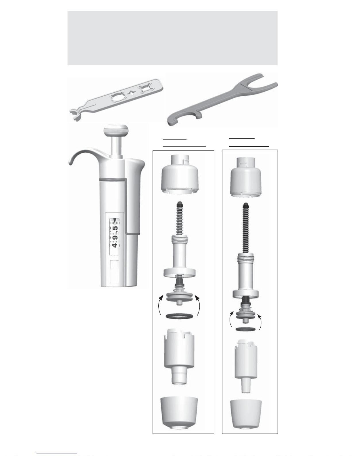
63
Spare parts
Ersatzteile
Pieces detachees
Piezas de recambio
パーツ及び付属品
1-10 ml
6-10 ml Fixed
2
10
11
13
14
0,5-5 ml
2-5 ml Fixed
10
11
13
14
1
12*
12*
* 42
* 42
12. 1033050 10ml
12. 1030230 5ml
42. 2212260N 1-10ml
42. 2212250N 0.5-5ml
* 12. O-ring
* 42. Tip Cone assy
1062800 1μl-10ml
1062930 MCP
Page 64

64
100-1000μl
250 / 500 / 1000μl
Fixed
12
14
15
13
11
10
16
100-1000μl
250 μl Fixed
500 μl Fixed
1000μl Fixed
17. 1030020
42. 2212240
30-300μl
17. 1033330
42. 2212220
30-300μl
12
14
15
13
11
10
16
* 17. O-ring
* 42. Tip Cone assy
17*
17*
* 42
* 42
Page 65

65
20-200μl
200 μl Fixed
17. 1030160
42. 2212210
10-100μl
25 μl Fixed
50 μl Fixed
100 μl Fixed
17. 1030510
42. 2212200
10-100μl
25 / 50 / 100μl
Fixed
12
13
11
10
12
14
15
13
11
10
16
* 17. O-ring
* 42. Tip Cone assy
17*
* 42
* 42
20-200μl
200μl Fixed
14
15
16
17
*
Page 66

66
2-20μl
2-20 μl Micro
20 μl Fixed
19. 1030380
20. 1033110
42. 2212190 2-20μl
42.
2212180 2-20μl Micro
42. 2212190 Fix 20μl
5-50μl
5-50 μl Micro
19. 1030500
20. 1033060
42. 2213050 5-50μl
42.
2213030 5-50μl Micro
1-10μl
1-10 μl Micro
10 μl Fixed
19. 1030380
20. 1030060
24. 1030170
42. 2212170
1-10μl
42.
2212110 1-10μl Micro
42. 2212170
Fix 10μl
1-10μl / 1-10μl Micro
10μl Fixed
12
13
12
13
11
10
14
15
17
16
18
21
22
14
15
17
16
18
21
22
23
* 19. O-ring
* 20. O-ring
* 24. O-ring
* 42. Tip Cone assy
* 42
* 42
19*
20*
24*
19*
20*
2-20μl / 2-20μl Micro
5-50μl / 5-50μl Micro
20μl Fixed
11
10
5-50μl
5-50μl
Page 67

67
0,5-5 μl
0,5-5 μl
19. 1030380
20. 1033160
24. 1030170
42. 2212100
0,2-2 μl
24. 1030170
28. 2205730
42. 2212090
12
13
12
13
11
10
11
10
14
15
17
16
18
21
22
14
15
17
16
18
19
21
20
22
23
0,2-2 μl
23
27
* 19. O-ring
* 20. O-ring
* 24. O-ring
* 28. Sealing
Combination
* 42. Tip Cone assy
* 42
* 42
19*
20*
28*
24*
24*
Page 68

68
1-10μl
42. 2209110 12 pcs
50. 2212330N 8-ch
50. 2212340N 12-ch
15
12
13
40
32
16
18
39
31
35
33
36
37
38
41
30
46
21
21
23
44
43
45
17
22
* 42. Tip Cone assy
* 50. Module
42*
* 50
47
Page 69

69
32
31
30
35
34
36
10-100μl
33
5-50μl
33
30
31
32
34
35
36
36
21
33
31
32
34
30
35
37
15
12
13
17
16
46
45
43
44
20
23
18
22
42*
42*
42*
* 50
30-300μl
42. 2209350 12 pcs
50. 2212390N 8-ch
50. 2212400N 12-ch
10-100μl
42. 2212440 12 pcs
50. 2212370N 8-ch
50. 2212380N 12-ch
5-50μl
42. 2212750 12 pcs
50. 2212350N 8-ch
50. 2212360N 12-ch
* 42. Tip Cone assy
* 50. Module
37
47
30-300μl
Page 70

70
15
12
13
17
16
46
45
43
44
21
21
23
24
18
23
31
37
33
22
42
*
* 42. Tip Cone assy
* 50. Module
* 50
1-10μl 16-ch
42. 2212760 8 pcs
50. 2212410N
47
Page 71

71
15
12
13
17
16
46
45
43
44
21
21
23
24
18
23
22
* 42. Tip Cone assy
* 50. Module
* 50
5-50μl 16-ch
42. 2207950 8 pcs
50. 2212420N
33
30
31
34
37
32
35
36
42
*
Picture / Abbildung / Illustration /
Imagen / 図
47
Page 72

72
Finntip (sterile and non-sterile)
10 Micro
10 Flex micro
20 Micro
50 Micro
250 Univ
200 Ext
200 Flex
300
300 Flex
1000 Ext
1000
1000 Flex
1200 Flex
5 ml
10ml
10ml Flex Ext
FP F1 0.2 - 2 μl
••••
FP F1 0.5 - 5 μl
••••
FP F1 1 - 10 μl micro
••••
FP F1 1 - 10 μl
•••••
FP F1 2 - 20 μl micro
••
FP F1 2 - 20 μl
•••••
FP F1 5 - 50 μl micro
•
FP F1 5 - 50 μl
•••••
FP F1 10 - 100 μl
•••••
FP F1 20 - 200 μl
•••••
FP F1 30 - 300 μl
••
FP F1 100 - 1000 μl
••••
FP F1 0.5 - 5 ml
•
FP F1 1 - 10 ml
••
FP F1 Fixed Volume 10 μl
•••••
FP F1 Fixed Volume 20 μl
•••••
FP F1 Fixed Volume 25 μl
•••••
FP F1 Fixed Volume 50 μl
•••••
FP F1 Fixed Volume 100 μl
•••••
FP F1 Fixed Volume 200 μl
•••••
FP F1 Fixed Volume 250 μl
••••
FP F1 Fixed Volume 500 μl
••••
FP F1 Fixed Volume 1000 μl
••••
FP F1 Fixed Volume 2000 μl
•
FP F1 Fixed Volume 3000 μl
•
FP F1 Fixed Volume 5000 μl
•
FP F1 Fixed Volume 10000 μl
••
FP F1 8-Ch 1-10 μl
••••
FP F1 12-Ch 1-10 μl
••••
FP F1 8-Ch 5-50 μl
•••••
FP F1 12-Ch 5-50 μl
•••••
FP F1 8-Ch 10-100 μl
•••••
FP F1 12-Ch 10-100 μl
•••••
FP F1 8-Ch 30-300 μl
••
FP F1 12-Ch 30-300 μl
••
FP F1 16-Ch 1-10 μl
••
FP F1 16-Ch 5-50 μl
•
Finnpipette F1 and Finntip compatibility table
Kompatibilitätstabelle für Finnpipette F1 und Finntip-Spitzen
Tableau de compatibilité Finnpipette F1 et Finntip
Tabla de compatibilidades Finnpipette F1 y Finntip
Finnpipette F1とFinntip適合表
Page 73

73
Finntip Filter (sterile)
10 Micro
10 Flex micro
20 Micro
50 Micro
10 Univ
20 Univ
30 Univ
30 Flex
100 Ext
100 Univ
100 Flex
200 Ext
200 Flex
200 Univ
300
300 Flex
1000 Ext
1000
1000 Flex
1200 Flex
5 ml
10ml
10ml Flex Ext
••••
••••
••••
••••
••
••••••••••••
••••••••
•••••
••
•••••••
••••
•••
•••••••••••
••••••••
••••••••
•••••
••••
••••
••••
•••
••
••••
••••
••••••••
••••••••
••••••••
••••••••
••
••
••
•
Finntip compatibility chart 1508760-04
Page 74

74
Tip Ordering Information
Bestellinformation: Pipettenspitzen
Renseignements pour commander des cônes
Información para pedidos del portapuntas
チップの注文について
Code Finntip Volume Qty
* 9400300 10 Micro 0,2-10 μl 10x96/rack
9400303 10 Micro sterile 0,2-10 μl 10x96/rack
* 94060100 Flex 10 0,2-10 μl 10x96/rack
94060103 Flex 10 sterile 0,2-10 μl 10x96/rack
* 9400610 20 Micro 0,2-20 μl 10x384/rack
9400613 20 Micro sterile 0,2-20 μl 10x384/rack
* 9400370 50 Micro 0,2-50 μl 10x384/rack
9400373 50 Micro sterile 0,2-50 μl 10x384/rack
* 9400130 200 Ext 5-200 μl 10x96/rack
9400133 200 Ext sterile 5-200 μl 10x96/rack
* 94060310 Flex 200 1-200 μl 10x96/rack
94060313 Flex 200 sterile 1-200 μl 10x96/rack
* 9400260 250 Univ. 0,5-250 μl 10x96/rack
9400263 250 Univ. sterile 0,5-250 μl 10x96/rack
* 9401250 300 5-300 μl 10x96/rack
9401253 300 sterile 5-300 μl 10x96/rack
* 94060510 Flex 300 5-300 μl 10x96/rack
94060513 Flex 300 sterile 5-300 μl 10x96/rack
* 9401110 1000 100-1000 μl 10x96/rack
9401113 1000 sterile 100-1000 μl 10x96/rack
* 94060710 Flex 1000 100-1000 μl 10x96/rack
94060713 Flex 1000 sterile 100-1000 μl 10x96/rack
* 9402070 5 ml 1-5 ml 5x54/rack
9402073 5 ml sterile 1-5 ml 5x54/rack
* 9402160 10 ml 1-10 ml 5x24/rack
9402163 10 ml sterile 1-10 ml 5x24/rack
94060970 Flex 10ml Ext 1-10 ml 100 pcs/bag
94060973 Flex 10ml Ext sterile 1-10 ml 50 pcs/bag
* Also available in bags
Code Finntip Filter Volume Qty
94052000 10 Micro sterile 0,2-10 μl 10x96/rack
94056980 Flex 10 sterile 0,2-10 μl 10x96/rack
94052100 10 sterile 0,5-10 μl 10x96/rack
94052020 20 Micro sterile 0,2-20 μl 10x384/rack
94052150 20 sterile 0,5-20 μl 10x96/rack
94052160 30 sterile 0,5-30 μl 10x96/rack
94056510 Flex 30 sterile 5-30 μl 10x96/rack
94052060 50 Micro sterile 0,2-50 μl 10x384/rack
94052200 100 μl sterile 0,5-100 μl 10x96/rack
94052310 100 μl Ext sterile 5-100 μl 10x96/rack
94056520 Flex 100 sterile 5-100 μl 10x96/rack
94052300 200 μl sterile 0,5-200 μl 10x96/rack
94052320 200 μl Ext sterile 5-200 μl 10x96/rack
94056380 Flex 200 sterile 1-200 μl 10x96/rack
94052350 300 μl sterile 5-300 μl 10x96/rack
94056580 Flex 300 sterile 5-300 μl 10x96/rack
94052410 1000 μl sterile 100-1000 μl 10x96/rack
94052430 1000 μl Ext sterile 100-1000 μl 5x96/rack
94056710 Flex 1000 sterile 100-1000 μl 10x96/rack
94052550 5 ml sterile 1-5 ml 5x54/rack
94052600 10 ml sterile 1-10 ml 5x24/rack
94056970 Flex 10 ml Ext sterile 1-10 ml 50/bag
Page 75

75
Page 76

76
150 89 80 -0 2
thermofi sher.com
info.pipettes@thermofi sher.com
© 2016 Thermo Fisher Scientifi c Inc. All rights reserved. All trademarks are the property of Thermo Fisher
Scientifi c Inc. and its subsidiaries. Specifi cations, terms and pricing are subject to change. Not all products
are available in all countries. Please consult your local sales representative for details.
Thermo Fisher Scientific
Ratastie 2, P.O.Box 100
FI-01621 Vantaa
Finland
 Loading...