

Thermo Scientific FD1530M, FD1500M, FD1530MCN, FD1530M-33, FD1535M Installation And Operation Manual
...Page 1

Installation
Thermo Scientific Thermolyne Furnace
Benchtop Indus
and
Operation Manual
trial/
Type FD1500M,
Type Models:
FD1530M, FD1530MCN,
FD1530M-33, FD1535M,
FD1540M, FD1540MCN,
FD1540M-33, AND
FD1545M.
1
Page 2

©
2012 These operating instructions are protected by copyright. Rights resulting thereof, particularly
reprint, photomechanical or digital post processing or reproduction, even in part, are only allowed with
the written consent of
Thermo Fisher Scientific.
Trademarks
Thermo Scientific is a brand owned by Thermo Fisher Scientific Inc.
All trademarks mentioned in the operating instructions are the exclusive property of the respective
manufacturers.
This regulation does not apply to reproductions for in-plant use.
The contents of this operating instructions manual may change at any time and without any prior
notice.
Page 3

Table of Contents
IMPORTANT INFORMATION
This manual contains important operating and safety information. The user must carefully
read and understand the contents of this manual prior to the use of this equipment.
Safety Information ..............................................................................................................................................4
Alert Signals..................................................................................................................................................4
Warnings ......................................................................................................................................................4
Introduction..........................................................................................................................................................6
Intended Use ................................................................................................................................................6
General Usage..............................................................................................................................................6
Principles of Operation ................................................................................................................................6
General Specifications ....................................................................................................................................... 7
Environmental Conditions ............................................................................................................................8
Declaration of Conformity ............................................................................................................................8
Unpacking ..........................................................................................................................................................9
Installation ........................................................................................................................................................10
Site Selection ..............................................................................................................................................10
Electrical Connections ................................................................................................................................10
Operation, All Models ........................................................................................................................................11
Power Switch ............................................................................................................................................11
Cycle Light ..................................................................................................................................................11
Door Safety Switches ................................................................................................................................11
Digital Readout ..........................................................................................................................................11
Single Setpoint Model w/OTP ..........................................................................................................................12
Eurotherm 3216 Controller Operation.........................................................................................................12
Basic Operation ..........................................................................................................................................12
Button and Indicators..................................................................................................................................12
To View or Change the Setpoint ................................................................................................................13
To View Display Units ................................................................................................................................13
Controller Parameters ................................................................................................................................13
Alarms ........................................................................................................................................................14
Sensor Break Protection ............................................................................................................................14
Over-Temperature Protection (OTP) ..........................................................................................................14
Tuning ........................................................................................................................................................15
Single Ramp & Dwell with OTP ........................................................................................................................16
Functions ....................................................................................................................................................16
Program Overview ......................................................................................................................................17
Setpoint rete limit Setup..............................................................................................................................17
Running the Program..................................................................................................................................17
Holding the Program ..................................................................................................................................18
Stopping the Program ................................................................................................................................18
Clearing the Flashing End ..........................................................................................................................18
Verifying a Running Program ......................................................................................................................18
8 Segment Programmable Model w/OTP..........................................................................................................19
Basic Operation ..........................................................................................................................................19
To Change the Setpoint ..............................................................................................................................19
To View Display Units ................................................................................................................................19
To View the % Output Power ......................................................................................................................19
2
Page 4

TABLE OF CONTENTS
Buttons and Indicators ................................................................................................................................20
Controller Parameters ................................................................................................................................21
Alarms ........................................................................................................................................................23
Sensor Break Protection ............................................................................................................................23
Over-Temperature Protection (OTP) ..........................................................................................................24
To Operate the Controller as a Single Setpoint Controller ........................................................................24
Programming the Controller........................................................................................................................24
Running a Program (8 Segment Programmable Models) ..........................................................................29
Holding a Program ......................................................................................................................................29
Cancelling a Program ................................................................................................................................29
Tuning ........................................................................................................................................................29
Autotuning ..................................................................................................................................................31
Adaptive Tuning ..........................................................................................................................................31
Furnace Loading ........................................................................................................................................32
Preventative Maintenance ................................................................................................................................33
Troubleshooting ................................................................................................................................................34
Maintenance and Servicing ..............................................................................................................................36
To Replace a Heating Element ..................................................................................................................36
To Replace the Platinel II Thermocouple....................................................................................................36
To Replace Door Switch (Micro-Switch) ....................................................................................................37
To Realign Door Switches ..........................................................................................................................38
To Replace the Controller ..........................................................................................................................38
Replacement Parts............................................................................................................................................39
Wiring Diagrams ................................................................................................................................................40
Ordering Procedures ........................................................................................................................................42
3
Page 5
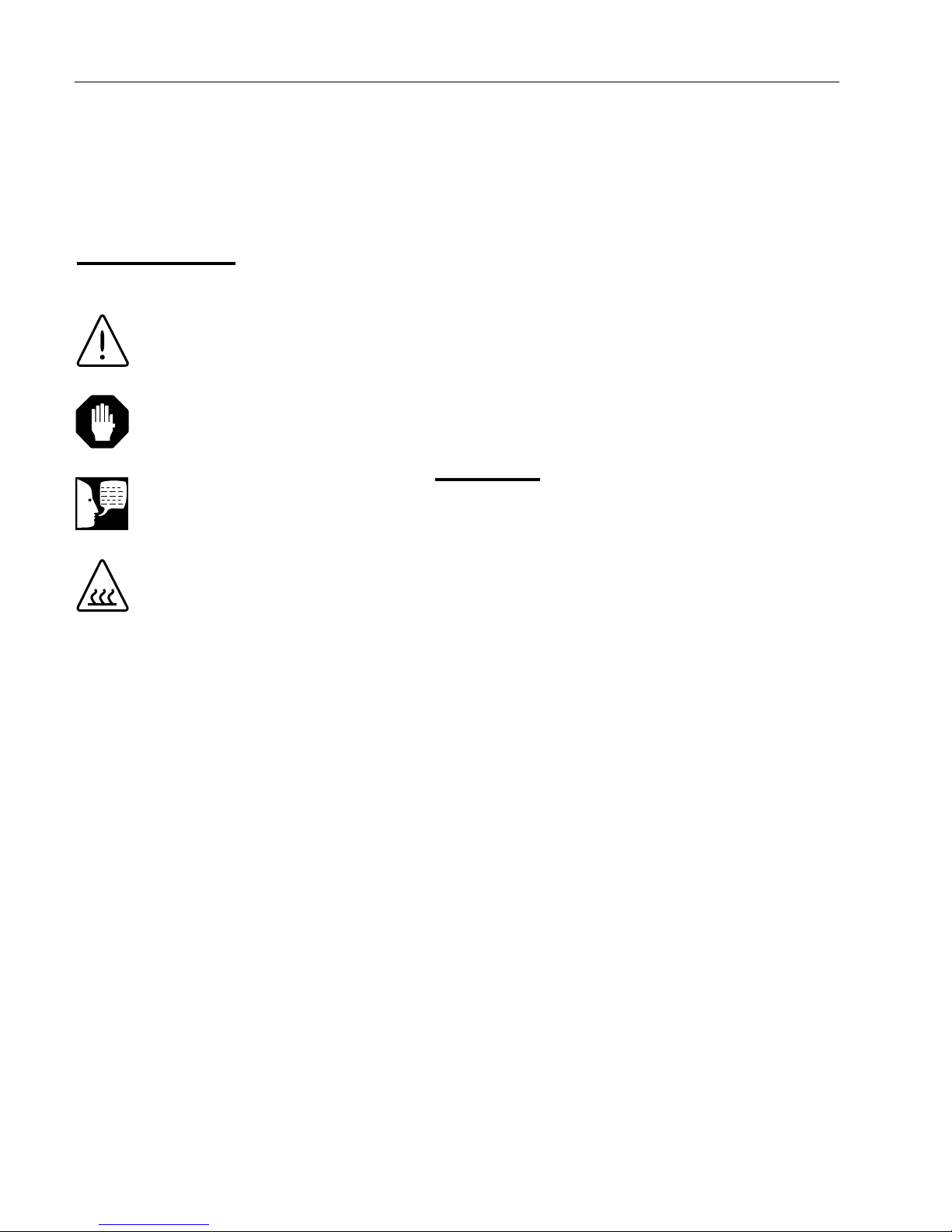
Safety Information
Alert Signals
Warning
Warnings alert you to a possibility of
personal injury.
Caution
Cautions alert you to a possibility of
damage to the equipment.
Note
Notes alert you to pertinent facts and
conditions.
Hot Surface
Hot surfaces alert you to a possibility
of personal injury if you come in
contact with a surface during use or
for a period of time after use.
This manual contains important operating and safety
information. The user must carefully read and understand
the contents of this manual prior to the use of this
equipment.
Your Thermolyne furnace has been designed with
function, reliability, and safety in mind. It is the user‟s
responsibility to install it in conformance with local codes.
For safe operation, please pay attention to the alert
signals throughout the manual.
Warnings
To avoid electrical shock, this furnace must:
1. Use a properly grounded electrical outlet of
correct voltage and current handling capacity.
2. Disconnect from the power supply prior to
maintenance and servicing.
3. Have the door switch operating properly.
To avoid burns, this furnace must:
Not to be touched on the exterior or interior
surfaces during use or for a period of time after
use.
To avoid personal injury:
1. Do not use in the presence of flammable or
combustible materials; fire or explosion may
result. This device contains components which
may ignite such materials.
2. Refer servicing to qualified personnel.
4
Page 6

SAFETY INFORMATION
Please note the following WARNINGS:
WARNING
This warning is presented for compliance with California Proposition 65 and other regulatory agencies and
only applies to the insulation in this product. This product contains refractory ceramic, refractory ceramic fiber
or fiberglass insulation, which can produce respirable dust or fibers during disassembly. Dust or fibers can
cause irritation and can aggravate preexisting respiratory diseases. Refractory ceramic and refractory
ceramic fibers (after reaching 1000°C) contain crystalline silica, which can cause lung damage (silicosis). The
International Agency for Research on Cancer (IARC) has classified refractory ceramic fiber and fiberglass as
possibly carcinogenic (Group 2B), and crystalline silica as carcinogenic to humans (Group 1).
The insulating materials can be located in the door, the hearth collar, in the chamber of the product or under
the hot plate top. Tests performed by the manufacturer indicate that there is no risk of exposure to dust or
respirable fibers resulting from operation of this product under normal conditions. However, there may be a
risk of exposure to respirable dust or fibers when repairing or maintaining the insulating materials, or when
otherwise disturbing them in a manner which causes release of dust or fibers. By using proper handling
procedures and protective equipment you can work safely with these insulating materials and minimize any
exposure. Refer to the appropriate Material Safety Data Sheets (MSDS) for information regarding proper
handling and recommended protective equipment. For additional MSDS copies, or additional information
concerning the handling of refractory ceramic products, please contact the Customer Service Department at
International at 1-800-438-4851.
5
Page 7

Introduction
Intended Use
The Type 1500 furnaces are general laboratory and heat
treating furnace. For optimum element life, it is suggested
that this furnace be used for applications requiring
temperatures from 212°F (100°C) to 2192°F (1200°C). For
maximum element life, it is recommended to operate the
furnace at temperatures from 212°F (100°C) to 1950°F
(1066°C) for continuous use, or temperatures from
1950°F (1066°C) to 2192°F (1200°C) for intermittent use.
Continuous use is operating the furnace for more than 3
hours and intermittent use is operating the furnace for
less than 3 hours.
The unit consists of: 1) heating chamber, 2) a digital
controller and 3) a door interlock relay for user safety.
General Usage
Do not use this product for anything other than its intended
usage.
Principles of Operation
The furnace chamber is heated by four electric resistance
heaters which are embedded in a refractory material. The
chamber is insulated with ceramic fiber insulation. For
safety, a door switch is incorporated to remove power
from heating elements when door is opened. The furnace
chamber is supported by the control section which also
houses the electrical connections.
6
Page 8

General Specifications
MODEL NUMBER
FD1540M,
FD1530M
FD1540M-33
FD1530M-33
FD1545M
FD1535M
CHAMBER
DIMENSIONS
IN. (CM)
WIDTH
4
(10 CM)
4
(10 CM)
4
(10 CM)
HEIGHT
3-3/4
(9.5 CM)
3-3/4
(9.5 CM)
3-3/4
(9.5 CM)
DEPTH
9
(22.9CM)
9
(22.9 CM)
9
(22.9 CM)
OVERALL
DIMENSIONS
IN. (CM.)
WIDTH
HEIGHT
11 (28
CM)
16-1/2
(42 CM)
11 (28
CM)
16-1/2
(42 CM)
11 (28
CM)
16-1/2
(42 CM)
DEPTH
18
(46 CM)
18
(46 CM)
18
(46 CM)
WEIGHT
LBS.
(KG)
42 LBS
(19 KG)
42 LBS
(19 KG)
42 LBS
(19 KG)
ELECTRICAL
RATINGS
VOLTS
240
220-240
120
AMPS
9.3 6.5
18.6
WATTS
2230
1560
2230
FREQ.
50/60
50/60
50/60
PHASE
1 1
1
OPERATING
TEMP RANGE
CONT.
100°C-1066°C
100°C-1066°C
100°C-1066°C
INTERMITTENT
1066°C-1200°C
1066°C-1200°C
1066°C-1200°C
7
Page 9

EN 61326-1
Electrical equipment for measurement, control, and
laboratory use; Part I: General Requirements
Safety: EN 61010-1
EN 61010-2-010
Safety requirements for electrical equipment for
measurement, control, and laboratory use;
Part I: General Requirements
Part II: Particular requirements for laboratory equipment for
the heating of materials
GENERAL SPECIFICATIONS
Environmental Conditions
Operating: 17°C - 27°C; 20% to 80% relative humidity, non-condensing. Installation Category II
(over-voltage) in accordance with IEC 664. Pollution Degree 2 in accordance with IEC 664.
Altitude limit: 2,000 meters.
Storage: -25°C to 65°C; 20% to 80% relative humidity.
Declaration of Conformity
(For -33 models only)
Thermo Scientific hereby declares under its sole responsibility that this product conforms with the technical
requirements of the following standards: EMC:
per the provisions of the Electromagnetic Compatibility Directive 2006/95/EC,
and per the provisions of the Low Voltage Directive 2004/108/EC.
The authorized representative located within the European Community is:
Electrothermal Engineering Ltd.
419 Sutton Road
Southend On Sea
Essex SS2 5PH
United Kingdom
Copies of the Declaration of Conformity are available upon request.
8
Page 10

Unpacking
Visually check for any physical damage to the shipping
container. Inspect the equipment surfaces that are
adjacent to any damaged area. Unpack furnace from
box. The owner‟s manual and door handle are included
in the box. After unpacking the furnace, attach the door
handle and remove packing material from inside furnace
chamber. The furnace is supplied with one hearth plate.
The 120V models are not supplied with a power cord
because current requirements are too great to be
handled by ordinary power cords and standard wall
supply.
9
Page 11

Installation
Caution
Be sure ambient temperature does not
exceed 104°F (40°C). The recommended ambient temperature is 17°C27°C. Ambient above this level may
result in damage to the controller.
Caution
Allow at least six inches of space
between the furnace and any
combustible surface. This permits the
heat from the case surface to escape
so as not to create a possible fire
hazard.
Warning
To avoid electrical shock, this furnace
must be installed by a competent
electrician who ensures compatibility
among furnace specification, power
source and ground code requirements.
Site Selection
Install furnace on a sturdy surface and allow adequate
space for ventilation.
Electrical Connections
The electrical specifications are located on the specification
plate on the back of the furnace. Consult Thermo Scientific
if your electrical service is different than those listed on the
specification plate. Prior to connecting your Type 1500 furnace
to your electrical supply, be sure the two position power switch
is in the OFF position.
Your 120V Type 1500 furnace may be wired either directly
through a conduit system or by using a power cord and
plug which conforms to the National Electrical Codes and
electrical code requirements of your area. The terminal
block to be used in wiring is located on the lower rear of
the furnace. For 120V supply connections, use 14 AWG
or larger wires suitable for at least 105°C (221°F).
10
Page 12
Operation, All Models
Warning
To avoid personal injury do not use in the
presence of flammable or combustible
chemicals; fire or explosion may result.
This device contains components which
may ignite such materials.
Hot Surface
Caution: Avoid Contact. To avoid
burns, this furnace must not be
touched on the exterior or interior surfaces during use or for a period of time
after use.
Warning
Always wear safety glasses or a safety
shield and high temperature gloves
when loading or unloading the furnace.
Long sleeved, fire retardant clothing and
a fire retardant apron is also
recommended.
Warning
To avoid electric shock, the door safety
switch must be operating properly.
Power Switch
Both the ON/OFF power switch and the digital display will
illuminate when power is switched ON. The furnace will
begin to heat to the controller‟s current setpoint. (See the
instructions for your type of controller for information on
checking and setting the setpoint).
Cycle Light
The amber cycle light will illuminate whenever the power
is being applied to the heating elements. The cycle light
will flicker on/off as furnace reaches setpoint.
Door Safety Switches
The door safety switches remove power from the heating
elements when the door is opened. Open and close the
door a few times; note that the amber CYCLE light will be
out when door is open. This check must be done when
furnace is heating or when cycle light is illuminated. If this
condition is not true, consult the Troubleshooting section
before proceeding.
Digital Readout
The digital readout continuously displays chamber
temperature.
11
Page 13
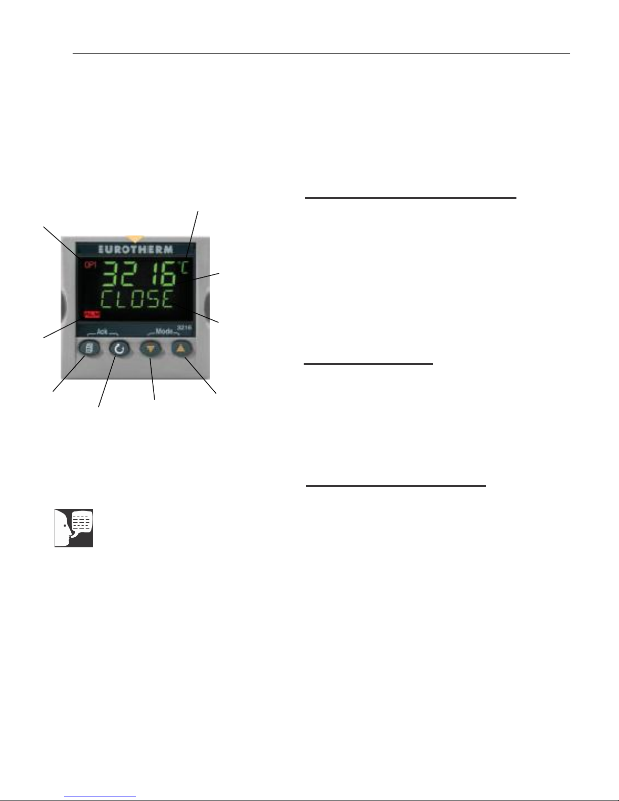
PAGE
Button
SCROLL
Button
DOWN
ARROW
Button
UP ARROW
Button
SetPoint (SP)
Display and
Scolling Text
Messages
4 Digit
Process Value
(PV) Display
Unit of Measure
Alarm
Beacon
Output(s)
Status
Beacon
Single Setpoint Models
Note:
If at any time you want to return to the
HOME DISPLAY, press PAGE button.
Single Setpoint w/OTP
Models FD1530M, FD1530MCN,
FD1530M-33, FD1535M
Eurotherm 3216 Controller
Operation
The single setpoint model w/OTP furnace controller is
a single setpoint controller, which provides a single
digital display to indicate the current chamber
temperature or setpoint temperature. This temperature
controller features sensor break protection, self-tuning
capability and over temperature protection (OTP) with
an additional OTP relay device.
Basic Operation
When the controller is turned ON it will perform a short
self-test and then display a default page. The
measured value (process value) is found in the upper
display and the setpoint is found in the lower display.
12
Buttons and Indicators
OP1 (Output 1): Illuminates when the output is ON
(normally heating).
OP2 (Output 2): Illuminates when the output is ON
(normally cooling).
OP4 (Output 4): Illuminates when the AA relay output
is ON (will go on during an alarm situation).
PAGE button: Allows you to select a new list of
parameters.
SCROLL button: Allows you to select a parameter
within a list of parameters.
DOWN button: Allows you to decrease a value.
UP button: Allows you to increase a value.
Page 14

SINGLE SETPOINT MODEL W/OTP
To Change the Setpoint
If you want to change the setpoint, press the SCROLL
button until “SP1” is displayed. Press the UP or
DOWN button until the desired setpoint value is
displayed and then release the button. A few seconds
after the button is released, the controller will accept
the new value and is indicated by a brief flash of the
display. Press PAGE button to return to HOME
DISPLAY.
To View the Display Units
Press SCROLL until “UNITS” is displayed. The
temperature units are also shown on the HOME
DISPLAY to the right of the measured value (process
value).
Temperature units can be changed by pressing up and
down buttons. Choice of Celsius (°C), Fahrenheit (°F),
Kelvin (°K), Percentage (%), or None (nonE).
Controller Parameters
Home display
13
°C, °F, °K, %, or None: Temperature units in Celsius
(default), Fahrenheit, Kelvin, Percentage (PErc), or
None (nonE).
A1.DHI: Deviation high alarm.
A2.HI: High Limit alarm. Read Only.
A3.LO: Low Limit alarm. Read Only.
A.TUNE (tune): One-shot autotune enable.
WRK.OP: Working Output power. Read Only.
PV.OFS: Process Value Offset. Read Only.
SP.RAT: Ramp Rate Setpoint (default units is
minutes).
DWELL: Time for dwell or delay (default units is
minutes).
T.STAT: Timer Status. Active only when timer is
active.
TM.CFG: Timer configuration.
Page 15

SINGLE SETPOINT MODEL W/OTP
Pid List
PB: Proportional band (in display units).
TI: Integral time in seconds.
TD: Derivative time in seconds.
ACCESS List Code: Access code (Code needed to
enter or change the other configuration parameters
which are not normally accessible). Not accessible.
Alarms
The controller will flash an alarm message in the home
display if an alarm condition is detected.
A2.HI: Measured value full scale high alarm.
A1.DHI: Measured value deviation high alarm.
S.br: Sensor break: check that sensor is connected
correctly.
LBR: Loop break: check that the heating circuits are
working properly.
Ld.F: Heater Circuit fault: indication of either an open
or short solid state relay, a blown fuse, missing supply
or open circuit heater.
14
Sensor Break Protection
This controller provides sensor break protection in the
event the thermocouple opens. If an open
thermocouple condition occurs, the digital display will
blink “S.br” and the power to the heating element will
be shut OFF (Cycle light will extinguish).
Over-Temperature Protection
(OTP)
The OTP will be in effect during any alarm condition
when the temperature of the furnace has deviated
beyond the limit. The “Deviation High” alarm is the only
alarm value, which can be changed. To change it,
press the SCROLL button until “A1.DHi” appears on
the display. Press the UP or DOWN button to select
the OTP value you desire. We recommend a value of
Page 16

SINGLE SETPOINT MODEL W/OTP
Note:
Furnace must be at ambient
temperature before starting a tune.
“Stat” and “Sp.rr” must be set to OFF or
“tunE” will not initiate.
Note:
Tune has completed when “tunE”
stops flashing on display.
20° above your working temperature to provide
protection for your workload. In addition to over
temperature protection, units containing a single
setpoint controller w/OTP feature a mechanical OTP
relay device, which disconnects power from the
elements in an alarm condition.
Tuning
This controller incorporates a self-tuning feature, which
determines the optimum control parameters for the
best temperature accuracy with your load and setpoint.
Use this feature the first time you use your furnace and
each time you change either your setpoint or the type
of load you are heating. Thermo Fisher Scientific
recommends you use this feature to provide the best
temperature accuracy the controller can attain. To use
the tuning feature:
1. Start tuning with the process at ambient
temperature. This allows the tuner to calculate
the low cutback and high cutback values
more accurately.
2. Adjust the setpoint to your desired value.
3. Press the SCROLL button until display reads,
“A.TUNE.”
4. Press the UP or DOWN button to select, “on.”
5. Press the PAGE button to return to the HOME
DISPLAY. The display will alternately flash
between “tunE” and the HOME DISPLAY while
tuning is in progress.
6. The controller will then turn the heating on and
off to induce an oscillation. When the
measured value reaches the required setpoint
the first cycle will end.
7. Tuning will be complete after two oscillation
cycles and then the tuner will turn itself off.
8. Normal control function will resume after the
controller calculates tuning parameters.
15
Page 17

Single Setpoint with OTP
Single Ramp & Dwell
Note
These instructions are used with the Single Setpoint models with OTP only
Functions
This type of controller has single ramp and dwell
programming capabilities. The Ramp and Dwell can be
configured to five different modes.
1. Mode 1 (DWELL) The dwell time begins once
the setpoint reaches the set threshold. The
END TYPE action is executed when the dwell
timer reaches the end.
2. Mode 2 (DELY) The timer starts immediately
upon instrument power-up, or when run is
selected. The instrument remains in standby until
the time has elapsed. After the time has elapsed,
the instrument controls up to setpoint.
3. Mode 3 (SF.ST) Starts automatically on power
up. This is a soft-start function. If the PV is
below the Soft Start Threshold, then the power
is limited to the Soft Start Limit until the
threshold is met.
Mode 1 (Opt. 1)
Mode 2 (Opt. 2)
Mode 3 (Opt. 3)
(See models listed on front page).
16
Page 18

SINGLE RAMP & DWELL CONTROLLER
Note:
The program must be stopped and the
controller must be displaying the actual
temperature before beginning the
Setup.
Program Overview
A program mode can be set by changing the “TM.CFG”
variable (in the „Timer‟ menu) to “DWEL, DELY, or SF.ST.
Note: value of “None” deactivates the timer.
A Ramp rate may be set by changing the “SP.RAT”
variable (in the „SP‟ menu) to a value. The Ramp rate
units are set with the “RAMPU” variable (in the „SP‟
menu). The selections are Hour / Min / Sec.
The Dwell time can be set by changing the “DWELL”
variable (in the „Timer‟ menu) to the desired value. Dwell
time units are set with the “TM.RES” variable (in the
„Timer‟ menu). The selections are Hour / Min.
The program Status can be set by changing the “T.STAT”
variable to “run”, “hold”, or “res.” This variable will start,
hold, or stop the program.
SetPoint Rate Limit Setup
1. Press the SCROLL button until the “SP.RAT” (Ramp
Rate) is displayed.
2. Set the desired Ramp rate with the UP or DOWN
buttons, if the ramp to setpoint feature is needed. If the
Ramp rate is not needed, then set to “OFF” with the
feature is needed. If the Ramp rate is not needed,
then set to “OFF” with the UP or DOWN buttons.
17
3. Press the SCROLL button until “TM.CFG” (Ramp &
Dwell mode) will be displayed, select the desired mode
with the UP or DOWN buttons. (DWEL, DELY, or
SF.ST).
4. Press the SCROLL button until “DWELL” will
be displayed set the desired Dwell time with
the UP or DOWN buttons.
5. Press the PAGE button and SCROLL button together
until the Actual temperature is displayed.
Running the Program
1. Press the SCROLL button until “T.STAT” is displayed,
set to “run” with the UP or DOWN buttons; or from the
HOME DISPLAY, press UP and DOWN arrows together.
2. Press the PAGE button to display Actual temperature.
Page 19

SINGLE RAMP & DWELL CONTROLLER
Holding the Program
1. Press the SCROLL button until “T.STAT” is displayed.
Set to “hold” with the UP or DOWN buttons; or from the
HOME DISPLAY, press UP and DOWN arrows together.
2. Press the PAGE button to display Actual temperature.
Stopping the Program
Press the SCROLL button until “T.STAT” is displayed, Set to
“res” with the UP or DOWN buttons.
Clearing the Flashing End
Press the PAGE and SCROLL buttons at the same time.
Verifying a Running Program
Press the SCROLL button until “T.STAT” is displayed. The
display will show “run” if the program is running, “hold” if it is
paused or “res if it is not running. Press the PAGE button to
display actual temperature.
18
Page 20

8 Segment Programmable w/OTP
Models FD1540M, FD1540MCN, FD1540M33, FD1545M
Note
The controller will return to the HOME
DISPLAY if left idle for more than a
AUTO/MAN
Button
PAGE
Button
few seconds.
Note
Once the desired parameter has been
selected, depressing either the UP or
DOWN button will change the
parameter value. In all cases, the
value shown on the display is the
current working value of that
parameter.
Output 1
SCROLL
Button
DOWN ARROW
Display
Window
Button
Upper
Display
Actual
Temp.
Lower
Display
Setpoint
Temp.
RUN/HOLD
Button
UP ARROW
Button
The 8 segment programmable controller consists of a
microprocessor based three-mode PID (Proportional,
Integral, and Derivative), programmable temperature
controller with over-temperature protection and
appropriate output switching devices to control the
furnace. The dig- ital readout continuously displays
chamber (upper display) and setpoint (lower display)
temperatures unless the SCROLL or PAGE button is
depressed. The programmable controller can be used
as a single setpoint controller or as a programmable
controller. The 8 segment digital model enables eight
segments of programming.
Basic Operation
When the controller is turned ON, it will perform a short
self-test and then change to the HOME DISPLAY. The
HOME DISPLAY shows the measured temperature
(process value) in the upper display and the desired
value (setpoint) in the lower display.
To Change the Setpoint
If you want to change the setpoint, press the UP or
DOWN button until the desired setpoint value is
displayed in the lower display and then release the
button.
To View Display Units
From the HOME DISPLAY press the SCROLL button.
The display will briefly show the temperature units in
°C/F/K and then return to the HOME DISPLAY. (If you
require a different temperature unit call Customer
Service)
To View the % Output Power
From the HOME DISPLAY press the SCROLL button
twice. Press the UP or DOWN button to display the
value. This value is a read-only value and cannot be
changed.
19
Page 21

8 SEGMENT PROGRAMMABLE MODEL W/OTP
Buttons and Indicators
OP1 (Output 1): illuminates when the heating output of
the temperature controller is on.
AUTO/MAN: (Auto/Manual Mode): when the controller is
in the automatic mode the output automatically adjusts to
keep the temperature or process value at the setpoint.
The “AUTO” light will illuminate. The manual mode has
been disabled through factory configuration. Call
Customer Service for further information.
RUN/HOLD (Run/Hold button):
• Starts a program when pressed once—RUN light
illuminates.
• Holds a program when pressed again—HOLD light
illuminates.
• Cancels hold and continues running when pressed
again—HOLD light is off and RUN light illuminates.
• Exits a program when the button is held down for two
seconds—RUN and HOLD lights are off.
• At the end of a program the RUN light will flash.
• During holdback the HOLD light will flash.
PAGE button: allows you to choose a parameter from a
list of parameters.
SCROLL button: allows you to choose a parameter within a list of parameters.
UP button: allows you to increase the value in the lower
display.
DOWN button: allows you to decrease the value in the
lower display.
20
Page 22

8 SEGMENT PROGRAMMABLE MODEL W/OTP
Controller Parameters
Home Display
°C: measured temperature in Celsius. Temperature units
cannot be changed without entering the configuration.
Contact Customer Service if a different temperature unit
is required.
OP: % output power demand; displayed in lower display
(cannot be changed).
C.id: Controller identification number.
IdHi: Deviation High Alarm.
tunE: One-shot autotune enable.
run LiSt (Program Run List)
StAt: Displays the program status [OFF, run (running
active program), hoLd (program on hold), HbAc (waiting
for process to catch up), End (program completed)] in the
lower display. The controller will default to “OFF.”
FASt: Fast run through program (no/YES). The controller
will default to “no.”
SEG.d: Flash active segment type in the lower display of
the home display (no/YES). The controller will default to
“no.”
ProG LiSt (Program Edit List)
Hb: Press the UP or DOWN ARROW to select the hold-
back type [OFF (disables holdback), Lo (deviation low
holdback), Hi (deviation high holdback) or bAnd (deviation
band holdback)] for the entire program. The controller will
default to “OFF.”
Hb.U: Press the UP or DOWN ARROW to select the
holdback value (in display units).
rmP.U: Press the UP or DOWN ARROW to toggle
between ramp units (SEc, min or Hour). Controller will
default to “SEc.”
dwL.U: Press the UP or DOWN ARROW to toggle
between dwell units (SEc, min or Hour). Controller will
default to “SEc.”
21
Page 23

8 SEGMENT PROGRAMMABLE MODEL W/OTP
22
Cyc.n: Press the UP or DOWN ARROW to set the number of program cycles (1 to 999 or cont). The controller
will default to “cont.”
SEG.n: Press the UP or DOWN ARROW to select the
segment number (1-8 in 8 segment models).
tYPE: Press the UP or DOWN ARROW to select the
segment type [End (end of program), rmP.r = ramp rate
(ramp to a specified setpoint at a set rate), rmp.t = ramp
time (ramp to a specified temperature in a set time), dwEll
(to maintain a constant temperature for a set time), StEP
(climb instantaneously from current to specified temperature). The controller will default to “End.” Other parameters used with tYPE include; tGt target setpoint), Rate
(rate of temperature increase) and dur (time to target
setpoint or time to dwell)].
End.t: End segment type: dwELL (dwell continuous), rSEt
(reset) and S OP (End Segment Output power level.
AL LiSt (Alarm List)
IdHi: Deviation High Alarm.
Atun LiSt: (Autotune List)
tunE: One-shot autotune enable.
drA: Adaptive tune enable.
drA.t: Adaptive tune trigger level in display units. Range =
1—9999.
Pid LiSt
G.SP (Gain Setpoint): Is the temperature at which the
controller switches from the (SEt 1) PID values to the (SEt
2) PID values.
Pb: Proportional band in display units. (SEt 1)
ti: Integral time in seconds. (SEt 1)
td: Derivative time in seconds. (SEt 1)
Pb2: Proportional band. (SEt 2)
ti2: Integral time in seconds. (SEt 2)
td2: Derivative time in seconds. (SEt 2)
Page 24

8 SEGMENT PROGRAMMABLE MODEL W/OTP
ACCS LiSt (Access List)
Access Code (Code needed to enter or change the other
configuration parameters which are not normally
accessible.) Call customer service if this configuration is
required.
Alarms
The controller will flash an alarm message in the home
display if an alarm condition is detected.
IdHi: PV deviation high alarm.
2FSH: PV full scale high alarm.
3FSL: PV full scale low alarm.
LCr: Load current low alarm.
HCr: Load current high alarm.
S.br: Sensor break: check that sensor is connected cor-
rectly.
L.br: Loop Break: Check that the heating circuits are
working properly.
Ld.F: Heater Circuit Fault: indication of either an open or
short solid state relay, a blown fuse, missing supply or
open circuit heater.
SSr.F: Solid state relay failure indications in a solid state
relay: indicates either an open or short circuit in the SSR.
Htr.F: Heater failure: Indication that there is a fault in the
heating circuit: indicates a blown fuse, missing sup- ply or
open circuit heater.
Sensor Break Protection
This controller provides sensor break protection in the
event the thermocouple opens. If an open thermocouple
condition occurs, the digital display will Blink “S.br” and
the power to the heating element will be shut OFF (Cycle
light will extinguish).
23
Page 25

8 SEGMENT PROGRAMMABLE MODEL W/OTP
Note
The following alarm messages are
factory default settings and may vary if
you have changed the configuration of
your controller:
IDHi = 50°C
2FSH = 1025°C
Over-Temperature Protection
(OTP)
The OTP will be in effect during any alarm condition when
the temperature of the furnace has deviated beyond the
limit. The “Deviation High” alarm is the only alarm value
which can be changed. To change it, press the SCROLL
button until “idHi” appears on the display. Press the UP or
DOWN button to select the OTP value you desire. We
recommend a value of 20° above your working temperature
to provide protection for your workload.
To Operate the Controller as a
Single Setpoint Controller
1. Switch the circuit breaker to the “ON” position.
The setpoint temperature presently set in the
controller will appear in the lower display. (The
upper display indicates the actual chamber
temperature.)
2. To change the setpoint, press the UP or DOWN
button until the desired setpoint value is
displayed; then release the button.
3. The furnace will begin to heat if the new setpoint
temperature is higher than the present chamber
temperature.
Programming the Controller
The controller is capable of varying temperature
or process value with time through programming.
A program is stored as a series of segments and
can be run once, repeated a set number of times
or run continuously. To create a customized
program using the controller parameters listed
under “Controller Parameters” at the beginning of
this section, follow the procedures outlined in the
proceeding sections of this manual.
24
Page 26

8 SEGMENT PROGRAMMABLE MODEL W/OTP
Hb: Holdback
Holdback consists of a value and a type. If the measured
value lags behind the setpoint by an undesirable amount
during a ramp or dwell, the holdback feature can be used to
freeze the program at its current state (the HOLD light will
flash). The program will resume when the error comes
within the holdback value.
OFF: holdback is disabled.
Lo (Deviation Low Holdback): holds the program back
when process variable deviates below the setpoint by
more than the holdback value.
Hi (Deviation High Holdback): holds the program back
when process variable deviates above the setpoint by
more than the holdback value.
bAnd (Deviation Band Holdback): combines the
features of the high and low deviation holdback in that it
holds the program back when the process variable
deviates above or below the setpoint by more than the
hold- back value.
To set the holdback type:
1. Press the PAGE button until you reach the program list (ProG LiSt).
2. Press the SCROLL button until display reads,
“Hb.”
3. Press the UP or DOWN button to toggle
between “bAnd, Hi, Lo and OFF.”
Hb U: Holdback Value
To set the holdback value:
1. Press the PAGE button until you reach the program list (ProG LiSt).
2. Press the SCROLL button until display reads,
“Hb.U.”
3. Press the UP or DOWN button to enter a holdback value.
25
Page 27

8 SEGMENT PROGRAMMABLE MODEL W/OTP
rmP.U: Setting Ramp Units
Ramp units are time units which are used in “rmP.r”
segments (ramp to a setpoint at degrees per second, minute
or hour) and “rmP.t” segments (ramp to setpoint in a specific
amount of time). See “Setting the Segment Type” for an
explanation on how to set a ramp segment.
1. Press the PAGE button until you reach the pro-
gram list (ProG LiSt).
2. Press the SCROLL button until display reads,
“rmP.U.”
3. Press the UP or DOWN button to toggle
dwL.U: Setting Dwell Units
Dwell units are time units which are used in “dwELL”
segments (amount of time to remain at a specific
temperature). See “Setting the Segment Type” for an
explanation on how to set a dwell segment.
CYC.n: Setting the Number of Cycles
Set the number of times a group of segments or programs are to be repeated by following the steps listed
below.
between seconds, minutes and hours.
1. Press the PAGE button until you reach the pro-
gram list (ProG LiSt).
2. Press the SCROLL button until display reads,
“dwL.U.”
3. Press the UP or DOWN button to toggle
between seconds, minutes and hours.
1. Press the PAGE button until you reach the pro-
gram list (ProG LiSt).
2. Press the SCROLL button until display reads,
”CYC.n.”
3. Press the UP or DOWN button to select the
number of cycles you want to run or, press the
DOWN button to select “cont.” so the program
will run continuously.
26
Page 28

8 SEGMENT PROGRAMMABLE MODEL W/OTP
Setting the Segment Type
There are five segment types. Proceed with the following
steps according to the type of segment you have
selected.
rmP.r (Ramp)
To ramp linearly at a set rate to a specified temperature:
1. Press the PAGE button until you reach the program list (ProG LiSt).
2. Press the SCROLL button until display reads,
”tYPE.”
3. Press the UP or DOWN button until display
reads, “rmP.r.”
Steps 4 and 5 are used in the 4 program model only. If
you are using an 8 segment program, skip to step 6.
4. Press the SCROLL button until display reads
“Hb.”
5. Press the UP or DOWN button to toggle
between “bAnd, Hi, Lo and OFF.”
Note
The program ramp rate is designed to
reduce the heatup rate or cooling rate
that the furnace normally exhibits.
When not using this feature, the
furnace will operate at its maximum
heating and cooling capability.
Note
When the program ramp has ended or
has been reset, the furnace will
continue to maintain setpoint
temperature. It will not cool to ambient
temperature unless the setpoint is set
to ambient temperature by the program
or by the operator.
6. Press the SCROLL button until display reads,
“tGt.”
7. Press the UP or DOWN button to set a target
setpoint.
8. Press the SCROLL button until display reads,
”rAtE.”
9. Press the UP or DOWN button to select a value
in ramp units (seconds, minutes or hours; set in
the “rmP.U” parameter).
rmP.t
To ramp to a specified temperature at a set time:
1. Press the PAGE button until you reach the program list (ProG LiSt).
2. Press the SCROLL button until display reads,
“tYPE.”
27
Page 29

8 SEGMENT PROGRAMMABLE MODEL W/OTP
3. Press the UP or DOWN button until display
reads, “rmP.t.”
4. Press the SCROLL button until display reads,
“tGt.”
5. Press the UP or DOWN button to set a target
setpoint.
6. Press the SCROLL button until display reads,
“dur.”
7. Press the UP or DOWN button to select a time
in ramp units (seconds, minutes or hours; set in
the “rmP.U” parameter.
dwEll
To maintain a constant temperature for a specified time:
1. Press the PAGE button until you reach the program list (ProG LiSt).
2. Press the SCROLL button until display reads,
“tYPE.”
3. Press the UP or DOWN button until display
reads, “dwEll.”
4. Press the SCROLL button until display reads,
“dur.”
5. Press the UP or DOWN button to select a time
in dwell units (seconds, minutes or hours; set in
the “dwL.U” parameter).
StEP
To climb instantaneously from the current temperature to
a specified temperature.
1. Press the PAGE button until you reach the program list (ProG LiSt).
2. Press the SCROLL button until display reads,
“tYPE.”
3. Press the UP or DOWN button until the display
reads, “StEP.”
4. Press the SCROLL button until display reads,
“tGt.”
28
Page 30

8 SEGMENT PROGRAMMABLE MODEL W/OTP
5. Press the UP or DOWN button to set a target
setpoint.
End
To end or repeat a program:
1. Press the PAGE button until you reach the program list (ProG LiSt).
2. Press the SCROLL button until display reads,
“tYPE.”
3. Press the UP or DOWN button until display
reads, “End.”
4. Press the SCROLL button until display reads,
“End.t.”
5. Press the UP or DOWN button to toggle
between “dwEll” (an indefinite dwell at last target
level), “S OP” (End Segment Output Power) and
“rSET” (reset will revert back to setpoint in
Single Setpoint mode).
Running a Program (8 Segment
Programmable Models)
To run a program, press the RUN/HOLD button. (The
RUN light will illuminate).
Holding a Program
To put a running program on hold, press the RUN/HOLD
button. (The HOLD light will illuminate).
Cancelling a Program
To cancel a program, hold the RUN/HOLD button down
until the RUN and HOLD lights go off.
Tuning
The purpose of tuning your furnace is to match the
characteristics of your controller to the characteristics of the
29
Page 31

8 SEGMENT PROGRAMMABLE MODEL W/OTP
process being controlled. Good control is evidenced by:
stable, straight-line control of the setpoint temperature
with no fluctuations; No overshoot or undershoot of the
setpoint temperature; rapid restoration of the setpoint temperature when external disturbances cause deviations
from the setpoint.
Note
Display will flash “tu.ER” if an error
occurs during tuning. To clear the
error and restart tuning,
simultaneously press the PAGE and
SCROLL buttons and follow the steps
outlined in “Autotuning.”
Note
To stop the tuning function,
simultaneously press the PAGE and
SCROLL buttons.
This controller has automatic tuning features which install
optimum tuning parameters to give the best temperature
accuracy. No manual loading of tuning parameters is
needed. We recommend that you tune the furnace to your
specific application to obtain the best results. To provide
the best temperature accuracy possible, use these
features when you install your furnace and whenever you
change your application or procedure.
Tuning Error
The display will flash “tu.ER” if an error occurs during
tuning. To clear the error and restart tuning, simultaneously
press the PAGE and SCROLL buttons and follow the steps
outlined in “Autotuning.”
G.SP: Gain Scheduling
Gain scheduling is the automatic transfer of control
between two sets of PID values. The controller does this
at a presettable process value. Gain scheduling is used
for difficult control processes which show large changes
in their response time or sensitivity at high or low temperatures, or when heating or cooling.
The G.SP gain schedule setpoint is factory set at 700° C.
The G.SP must be adjusted to 200°C from the desired
setpoint temperature when tuning.
Setting the Transfer Point
If gain scheduling has been enabled, “G.SP will appear at
the top of the PID list. This sets the value at which the
transfer will occur. When the process value is below this
level, PID1 will be active and when it is above, Pid2 will
be active. Set a value between the control regions that
show the greatest change to achieve the best point of
transfer.
30
Page 32

8 SEGMENT PROGRAMMABLE MODEL W/OTP
Tuning
The two sets of PID values can be manually set or
automatically tuned. To tune automatically you must tune
above and below the transfer point G.SP. If the process
value is below the transfer point G.SP, the calculated
values will automatically be inserted into the (SEt 1) set
and if the process value is above G.SP, the calculated
values will automatically be inserted into the (SEt 2).
Autotuning
The Autotune feature automatically sets up the PID values
in the control parameters to suit new process conditions.
To tune your furnace using autotuning:
1. Load your furnace with a load similar to your
normal load and close the door.
2. Set the setpoint temperature.
3. Press the PAGE button until the display reads,
“Atun LiSt.”
4. Press the SCROLL button until “tunE OFF” is
displayed.
Note
Start tuning with the process at
ambient temperature. This allows the
tuner to calculate the low cutback and
high cutback values more accurately.
5. Press the UP or DOWN button to select “on.”
6. Simultaneously press the PAGE and SCROLL
buttons to return to the HOME DISPLAY. The
display will flash “tunE” while tuning is in
progress.
Adaptive Tuning
Adaptive tuning continuously evaluates tuning parameters.
Adaptive tuning automatically installs new values if better
accuracy is possible. Adaptive tuning should be used when
the characteristics of a process change due to load or
setpoint changes or, in a process that cannot handle the
oscillation caused by a one-shot tune.
To tune your furnace using adaptive tuning:
1. Load your furnace with a load characteristic of
those you intend to heat in it.
31
Page 33

8 SEGMENT PROGRAMMABLE MODEL W/OTP
2. Press the PAGE button until display reads, “Atun
LiSt.”
3. Press the SCROLL button until “drA OFF” is
displayed.
4. Press the UP or DOWN button to select “on.”
5. Press the SCROLL button until “drA.t” is
displayed.
6. Press the UP or DOWN button until the desired
trigger value is achieved.
Caution
Do not overload your furnace
chamber. If the load is to be heated
uniformly it should not occupy more
than the center two-thirds of the
furnace chamber. Failure to observe
this caution could result in damage to
furnace components.
Furnace Loading
1. For best results, use only the center 2/3 of the
furnace chamber.
2. If you are heating a number of small parts,
spread them throughout the center two-thirds of
the furnace chamber.
3. Keep objects away from thermocouple.
4. Use insulated tongs and mittens when loading
and unloading furnace.
5. Always wear safety glasses.
6. Use the hearth plates supplied to protect bottom
of chamber. Part # PHX2.
32
Page 34

Preventive Maintenance
Warning
Before using any cleaning or
decontamination method except those
recommended by Thermo Scientific,
users should check with Thermo
Scientific that the proposed method
will not damage the equipment.
Warning
Disconnect the furnace from power
supply before cleaning.
Warning
Opening the door for an extended
period of time will cause the painted
surfaces above the door to be
discolored or burnt.
Contamination is a major cause of element failure, therefore, when possible, remove the fume forming material
before heating (e.g., cleaning cutting oil from tool steel).
The resistance wire is high-grade nickel-chromium. Some
chemicals, notably sulphur, halogens, and cyanides,
attack this wire at high temperatures, so avoid spilling
these chemicals in the furnace or heating them any hotter
than necessary. The refractory cement helps to protect
the wire, but will not completely immunize it from damage.
All heating elements must be considered expendable, and
replacement is expected; however, reasonable care in
their use will greatly extend the service they will give. As
the manufacturer has no control over the use or care of
the elements, no specific service guarantee can be made.
Housekeeping is vital to your electric furnace—KEEP IT
CLEAN! Run your furnace up to 871°C (1600°F) empty
occasionally to burn off the contamination that may exist
on the insulation and elements. Run for approximately two
hours with the door slightly open. See warning.
Element life is reduced somewhat by repeated heating
and cooling. If the furnace is to be used again within a
few hours, it is best to keep it at the operating
temperature or at a reduced level such as 260°C
(500°F).
During normal use, the thermocouple in your furnace can
become oxidized and cause inaccurate readings; therefore, we suggest that if you regularly use your furnace you
should change your thermocouple once every six months
to assure the accuracy of your controller readings.
Clean by wiping the outside case of the unit with a damp
cloth and mild soap solution.
33
Page 35

Troubleshooting
PROBLEM
Cycle light does not
POSSIBLE CAUSES
The furnace is not connected
CORRECTIVE ACTION
Reconnect furnace to
illuminate.
to power supply.
power supply.
Incorrect power source.
Connect to correct power
source.
ON and OFF power switch
defective.
Replace power switch.
Defective cycle light.
Replace cycle light.
Door switch malfunction.
Realign or replace furnace door
safety switch.
Furnace does not heat.
No power.
Check power source and
fuses or breakers.
Defective electrical hookup.
Repair electrical hookup.
Thermocouple has oxidized and
opened the circuit.
Replace thermocouple.
Controller malfunction.
Replace controller.
Heating elements burned out.
Replace defective elements.
Solid state relay defective.
Replace solid state relay.
Door switch malfunction.
Re-align or replace door
switch.
Defective OTP relay.
Replace relay.
Controller over-temp. does not
Alarm output device malfunction.
Replace controller.
cut power to furnace chamber.
OTP relay malfunction.
Element shorted to ground.
Replace relay.
Replace faulty element.
Defective solid state relay. Replace relay.
Door switch does not cut power Door switch not functioning Realign or replace door safety
to heating elements. switch.
34
Page 36

Slow heatup.
Low line voltage.
Install line of sufficient size and
proper voltage. (Isolate furnace
from other electrical loads.)
Wrong heating element.
Install proper element.
Heating element burned out.
Replace element.
Heavy load in chamber.
Lighten load in chamber to
allow heat to circulate.
Repeated element burnout.
Overheating furnace.
Keep furnace under maximum
temperature. Closer supervision
of control setting.
Heating harmful materials.
Enclose material in container.
Clean up spills in and on
chamber. Ventilate chamber by
leaving top vent slightly open
when heating known harmful
reagents.
Contamination present from
Replace insulation material.
previous burnout.
Inaccurate temperature readout.
Oxidized or contaminated
thermocouple.
Replace thermocouple.
Poor thermocouple connection.
Tighten connections.
Improper loading procedures.
Use proper loading procedures.
Poor ventilation of control.
Clear area around furnace
control.
Thermocouple connections
reversed.
Reconnect thermocouple
correctly.
TROUBLESHOOTING
35
Page 37

Maintenance and Servicing
Warning
To avoid electrical shock, this furnace
must always be disconnected from the
power supply prior to maintenance
and service.
Perform only maintenance described
in this manual. Contact an authorized
dealer or our factory for parts and
assistance.
Refer servicing to qualified personnel.
Maintenance and Servicing
To Replace a Heating Element
1) Disconnect furnace from power supply.
2) Remove back terminal cover.
3) Loosen the nuts on the terminals of the element
to be replaced.
4) Straighten the leads of the old element.
5) Open the door and pull the defective element
out. (It may be easiest to turn the furnace so
that the element to be removed is on top.)
6) Slide the new element into place, threading the
leads through the insulating porcelain bushing in
the back of the furnace.
7) Reverse the disassembly procedure, making
sure you thread all element lead wires through
the insulating porcelain bushings on the back of
the furnace and cut off any excess element lead
wire after securing the leads to the terminal
points.
8) Replace the back terminal cover.
9) Reconnect furnace to power supply.
10) Test the operation of the furnace.
To Replace The Platinel II Thermocouple:
1) Disconnect the furnace from power supply.
2) Remove the back terminal cover. (Note
placement and connection of wires.)
3) Remove the screw and washer from clip holding
the thermocouple in place and remove the nuts
and washers on the thermocouple terminals.
36
Page 38

MAINTENANCE AND SERVICING
Note
Pull the thermocouple straight out of
the hole in the chamber to avoid damage to the insulation.
Note
Do not pull excessively on the internal
wires.
4) Remove the thermocouple.
5) Insert the new thermocouple straight through
hole in the chamber until the tip extends
approximately 1” into the chamber. Make sure
the thermocouple lead wire with the colored
bead is connected to the terminal marked
positive.
6) Secure the thermocouple extension wires to the
terminals (yellow to +).
7) Secure the thermocouple with clip, screw and
washer.
8) Replace the back cover.
9) Reconnect furnace to power supply.
10) Test the operation of the furnace.
To Replace Door Switch
(Micro-Switch)
1) Disconnect the furnace from power supply.
2) Remove the screws from the front dial and the
three bottom screws and lock washers on the
back cover of the control section.
3) Remove the back terminal cover.
4) Disconnect the two wires on terminals T1 and
T2 going to the control section.
5) Slide the control section forward.
6) Remove two screws and nuts from the door
switch and slide the switch from the wire rod.
7) Disconnect the wires from the door switch.
Identify or mark the wires disconnected to insure
proper placement and connection when reinstalling.
8) Reconnect the wires identified or marked in step
7 to the new door switch.
37
Page 39

MAINTENANCE AND SERVICING
Note
Center the rod from front to back of
hole in control case before tightening
screws.
9) Install the new door switch while sliding it over the
wire rod and secure with the screws and nuts
removed in step 6.
10) Slide the control section back and replace the
screws and lock washers described in step 2.
11) Connect wire marked T1 to terminal T1 and wire
marked T2 to terminal T2 with nuts removed in step
4.
12) Replace the back terminal cover with screws and
lock washers removed in step 3.
13) Test operation of door switch. (See next section “To
Realign Door Switches” step 5.)
14) Reconnect to power supply.
To Realign Door Switches
1) Disconnect the furnace from power supply.
2) Loosen the setscrew on the cam. Open the door
approximately 1” and rotate the cam
counterclockwise until you hear a click then rotate
the cam clock- wise until you hear a click, tighten the
set screw on adjusting cam.
3) Open and close the door; the switch should click
when the door is opened approximately 2” and 1” to
2” before the door is closed.
4) Reconnect to power supply.
5) To test the operation of the door switch: turn the
power switch on, set the control to a setting high
enough to keep the control from cycling, open and
close the door; the cycle light should turn OFF when
the door is opened approximately 2” and turn back
ON 1” to 2” before the door is closed.
To Replace the Controller
The controller plugs into a panel mounting sleeve, which
should be left permanently installed in the furnace
housing. To remove the controller, release the side clips
and slide the controller out. Do not attempt to dismantle
this unit further; replace it with a Thermolyne loaner or a
new unit.
38
Page 40

Part
Number
Description
Model
Number
EL11X11
Heating Element, Top or Bottom
FD1530M, FD1530MCN,
FD1535M, FD1540M,
FD1540MCN, FD1545M
EL11X12
Heating Element, Sides
FD1530M, FD1530MCN,
FD1535M, FD1540M,
FD1540MCN, FD1545M
EL1170X1
Heating Element, Top or Bottom
FD1530M-33,
FD1540M-33
EL1170X2
Heating Element, Sides
FD1530M-33,
FD1540M-33,
TC408X1A
Platinel II Thermocouple
All Models
RYX34
Solid State Relay
All Models
RYX56
Mechanical Relay (120V)
FD1535M, FD1545M
RYX57
Mechanical Relay (240 volt)
FD1530M, FD1530MCN,
FD1530M-33, FD1540M,
FD1540MCN, FD1540M-33
SWX78
Door Switch
All Models
CN71X178
Temperature Control, Single Set Point
FD1530M, FD1530MCN,
FD1535M
CN71X159
Temperature Control, Programmable
(2 ramp & 2 dwell)
FD1540M, FD1540MCN,
FD1545M
CN71X179
Temperature Control, Single Set Point
FD1530M-33
CN71X160
Temperature Control, 8 Segment
FD1540M-33
CR1170X1
Cord Set
FD1530M, FD1540M
CR1170X2
Cord Set
FD1530M-33, FD1540M-33
CR1170X3
Cord Set
FD1530MCN, FD1540MCN
SWX137
Power Switch (100-120 volt)
FD1535M, FD1545M
SWX138
Power Switch (208-240 volt)
FD1530M, FD1530MCN,
FD1530M-33, FD1540M,
FD1540MCN, FD1540M-33
PLX76
Cycle Light (100-120 volt)
FD1535M, FD1545M
PLX82
Cycle Light (208-240 volt)
FD1530M, FD1530MCN,
FD1530M-33, FD1540M,
FD1540MCN, FD1540M-33
DR327X3A
Door Only (Insulated)
All Models
PHX2
Hearth Plate
All Models
DR327X4A
Door Assembly (includes handle and
hinge.)
All Models
PT327X4A
Terminal Plate w/ Insulators
All Models
CAX94
Line Filter
-33 Models
TRX192
Terminal Block
All Models
Replacement Parts
39
Page 41

Wiring Diagrams
Single Setpoint w/OTP Control
40
Page 42

WIRING DIAGRAMS
41
Page 43

Ordering Procedures
Please refer to the Specification Plate for complete model
number, serial number, and series number when requesting service, replacement parts or in any correspondence
concerning this unit.
All parts listed herein may be ordered from the Thermo Scientific
dealer from whom you purchased this unit or can be obtained
promptly from the factory. When service or replacement parts are
needed, we ask that you check first with your dealer. If the dealer
cannot handle your request, then contact our Customer
Service Department at 800-438-4851.
Prior to returning any materials to Thermo Scientific,
please contact our Customer Service Department for a
“Return Materials Authorization” number (RMA).
42
Page 44

Important
For your future reference and when contacting the factory, please have the
following information readily available:
Model Number:
Serial Number:
Date Purchased:
The above information can be found on the dataplate attached to the
equipment. If available, please provide the date purchased, the source of
purchase (manufacturer or specific agent/rep organization), and purchase
order number.
IF YOU NEED ASSIS
TANCE:
LABORATORY PARTS and SERVICE
Phone: 800/438-4851
FAX: 828/658-2576
TECHNICAL SUPPORT
Phone: 800/438-4851
Page 45

275 Aiken Road
Asheville, NC 28804
United States
www.thermofisher.com
Thermo Fisher Scientific Inc.
LT1170X1
Rev. B
 Loading...