

Page 1

EVOS™ M5000 Imaging System
For Fluorescence and Transmitted Light Applications
Catalog Number AMF5000
Publication Number MAN0017563
Revision A.0
For Research Use Only. Not for use in diagnostic procedures.
Page 2

Revision
Date
Description
Information in this document is subject to change without notice.
Revision history MAN0017563
A.0 07 Aug 2018 New user guide for the EVOS™ M5000 Imaging System
Important Licensing Information
These products may be covered by one or more Limited Use Label Licenses. By use of these products, you accept the terms and
conditions of all applicable Limited Use Label Licenses.
Manufacturer: Life Technologies Corporation | 22025 20TH Ave SE | Bothell, WA 98021.
Trademarks
All trademarks are the property of Thermo Fisher Scientific and its subsidiaries unless otherwise specified.
Cy is a registered trademark of GE Healthcare UK Limited. Windows is a registered trademark of Microsoft Corporation. Kimwipes is a
registered trademark of Kimberly-Clark Corporation. Hoechst is a registered trademark of Hoechst GmbH.
© 2018 Thermo Fisher Scientific Inc. All rights reserved.
Page 3

Contents
About this guide ...................................................................................................................... 3
1. Product information .......................................................................................................... 4
Product description ......................................................................................................................................... 4
Standard items included ................................................................................................................................. 5
Instrument exterior components and mechanical controls ....................................................................... 6
Graphical user interface (GUI)....................................................................................................................... 8
2. Installation ........................................................................................................................ 9
Operating environment and site requirements ........................................................................................... 9
Prepare for installation ................................................................................................................................. 10
Install the instrument .................................................................................................................................... 10
3. Capture images ................................................................................................................ 15
Overview ........................................................................................................................................................ 15
Capture images .............................................................................................................................................. 16
Analyze and annotate captured images ..................................................................................................... 23
Show cell count .............................................................................................................................................. 27
4. Save captured images ...................................................................................................... 34
Save ................................................................................................................................................................. 34
Quick Save images ........................................................................................................................................ 35
5. Capture and save time lapse images ................................................................................ 36
Time Lapse tool.............................................................................................................................................. 36
Run a time lapse routine ............................................................................................................................... 36
6. Capture Z-Stack ............................................................................................................... 43
Z-Stack tool ..................................................................................................................................................... 43
Capture Z-stack images ................................................................................................................................ 43
7. Review saved images ....................................................................................................... 47
Overview ........................................................................................................................................................ 47
Review images ............................................................................................................................................... 47
Analyze saved images .................................................................................................................................. 49
8. Adjust instrument settings ............................................................................................... 50
Overview ........................................................................................................................................................ 50
Adjust objective settings ............................................................................................................................... 51
Calibrate white balance ................................................................................................................................ 53
Set saturated pixel options ........................................................................................................................... 54
General settings ............................................................................................................................................. 55
Configure network settings .......................................................................................................................... 56
EVOS™ M5000 User Guide
1
Page 4

9. Instrument care and maintenance ................................................................................... 58
General care .................................................................................................................................................... 58
Objective lens care ......................................................................................................................................... 58
Stage care ........................................................................................................................................................ 59
Decontamination procedures ....................................................................................................................... 59
Change EVOS™ LED light cubes ................................................................................................................. 60
Change the objectives ................................................................................................................................... 61
Calibrate the objectives ................................................................................................................................. 62
Appendix A: Troubleshooting ................................................................................................. 64
Image quality issues ...................................................................................................................................... 64
Software interface issues .............................................................................................................................. 65
Mechanical issues .......................................................................................................................................... 65
Appendix B: Graphical user interface (GUI) ............................................................................ 66
Capture tab ..................................................................................................................................................... 66
Review tab ...................................................................................................................................................... 71
Settings ............................................................................................................................................................ 72
Appendix C: System overview ................................................................................................ 74
Technical specifications ................................................................................................................................ 74
Operation principles and technical overview............................................................................................ 75
Appendix D: Safety ................................................................................................................. 76
Safety conventions used in this document ................................................................................................. 76
Symbols on instruments ............................................................................................................................... 77
Safety labels on instruments ........................................................................................................................ 79
General instrument safety ............................................................................................................................ 80
Chemical safety .............................................................................................................................................. 81
Chemical waste safety................................................................................................................................... 82
Electrical safety .............................................................................................................................................. 83
Physical hazard safety .................................................................................................................................. 84
Biological hazard safety ................................................................................................................................ 84
Safety and electromagnetic compatibility (EMC) standards ................................................................... 85
Documentation and support ................................................................................................... 86
2
EVOS™ M5000 User Guide
Page 5

About this guide
Audience
This user guide is for laboratory staff operating, maintaining, and analyzing data
using the Invitrogen™ EVOS™ M5000 Imaging System.
User attention
words
Two user attention words appear in this document. Each word implies a particular
Safety alert words
Three safety alert words appear in this document at points where you need to be
implies a particular level of observation or action, as defined below:
level of observation or action as described below.
Note: Provides information that may be of interest or help but is not critical to the
use of the product.
IMPORTANT! Provides information that is necessary for proper instrument
operation, accurate installation, or safe use of a chemical.
aware of relevant hazards. Each alert word—CAUTION, WARNING, DANGER—
CAUTION! – Indicates a potentially hazardous situation that, if not avoided,
may result in minor or moderate injury. It may also be used to alert against
unsafe practices.
WARNING! – Indicates a potentially hazardous situation that, if not
avoided, could result in death or serious injury.
DANGER! – Indicates an imminently hazardous situation that, if not
avoided, will result in death or serious injury. This signal word is to be
limited to the most extreme situations.
EVOS™ M5000 User Guide
3
Page 6

EVOS™ M5000
The Invitrogen™ EVOS™ M5000 Imaging System (Cat. No. AMF5000) is a fully
easy control.
EVOS™ M5000
The EVOS™ M5000 Imaging System is controlled by the integrated Invitrogen™
connectivity to the network and Thermo Fisher Cloud.
Product use
For Research Use Only. Not for use in diagnostic procedures.
1. Product information
Product description
Imaging System
Software
integrated, digital, inverted imaging system for four-color fluorescence and
transmitted-light applications.
It combines precision optics, a five-objective turret, an 18.5 inch high-resolution
LCD display (1920 × 1080 pixel resolution), and a highly sensitive Sony IMX265
monochrome CMOS camera (2048 × 1536 pixel resolution, 3.2 Megapixels) to
acquire images seamlessly through the intuitive user interface using a mouse for
EVOS™ M5000 Software through a graphical user interface (GUI), which is accessed
by the computer mouse and keyboard. The software is pre-installed to the
instrument and starts automatically when the instrument is powered on.
Key features of the EVOS™ M5000 Software include:
• Capture: Allows control over every aspect of the system for image capture
through a simple user interface. All images acquired can be saved in BMP, JPG,
PNG, and TIFF formats, or compiled into a video sequence in AVI or WMV
formats.
• Autofocus: Allows autofocus in fluorescence and brightfield modes.
• Z-stacking: Captures a series of images along the z-axis that can be saved
individually or combined into a Z-stack projection with a greater depth of field
than any of the individual source images.
• Time lapse: Allows you to create a time lapse movie using captured images.
• Review: Allows you to review, measure, and annotate captured images.
• Cell count: Allows you to count cells in fluorescence mode post-acquisition.
• Network and Thermo Fisher Cloud connectivity: Allows Wi-Fi and Ethernet
4
EVOS™ M5000 User Guide
Page 7

EVOS™ M5000
•
- Objectives, as ordered
EVOS™ M5000
•
- Mouse pad
EVOS™ M5000 user
•
- EVOS™ M5000 Imaging System Installation Guide (Pub. No. MAN0017783)
Standard items included
EVOS™ M5000 Imaging System, includes the following components and pre-
Imaging System
Accessories Kit
installed accessories:
- 18.5 in articulated LCD monitor (1920 ×1080 pixel resolution)
- Embedded PC (4 GB RAM)
- Light cube shipping restraint (remove before use)
- Stage lock pin (remove before use)
- EVOS
- Light cube tool (remove before use)
- Blank light cube (remove before use)
- LED light cubes, as ordered
EVOS™ M5000 Accessories Kit (located in the instrument box), contains:
- Wireless mouse and keyboard
- USB receiver (for wireless mouse and keyboard connection)
- USB Wi-Fi adaptor (for wireless network connection to Thermo Fisher
Cloud applications)
- USB 3.0 flash drive, 16 GB (for image storage, and preloaded with user
documentation)
- EVOS
- EVOS
- EVOS
- EVOS
- UV shield assembly
- Condenser Slider, Block (Cat. No. AMEP4688)
- Condenser Slider, 4X Pupil (Cat. No. AMEP4738)
- Condenser Slider, Diffusion for Brightfield Applications (Cat. No.
AMEPDFS1)
- Universal power supply (12 V, 5 A) and power cord (type B, North America)
- EVOS
- Accessories box with adjustable compartments
- Hex driver, 2 mm
™
Condenser Light Shield, 110 mm
™
Vessel Holder, Two 25 × 75 mm slides (Cat. No. AMEPVH001)
™
Vessel Holder, Universal (Cat. No. AMEPVH009)
™
Calibration Slide (Cat. No. AMEP4720)
™
Light Shield Box
™
Dust Cover
EVOS™ M5000 Quick Start Guide, printed (Pub. No. MAN0017765)
documentation
EVOS™ M5000 User Guide
• EVOS™ M5000 Imaging System Installation Guide, printed (Pub. No. MAN0017783)
• Pre-loaded to USB 3.0 flash drive (located in the accessories box):
™
- EVOS
- EVOS
M5000 User Guide (Pub. No. MAN0017763)
™
M5000 Quick Start Guide (Pub. No. MAN0017765)
5
Page 8
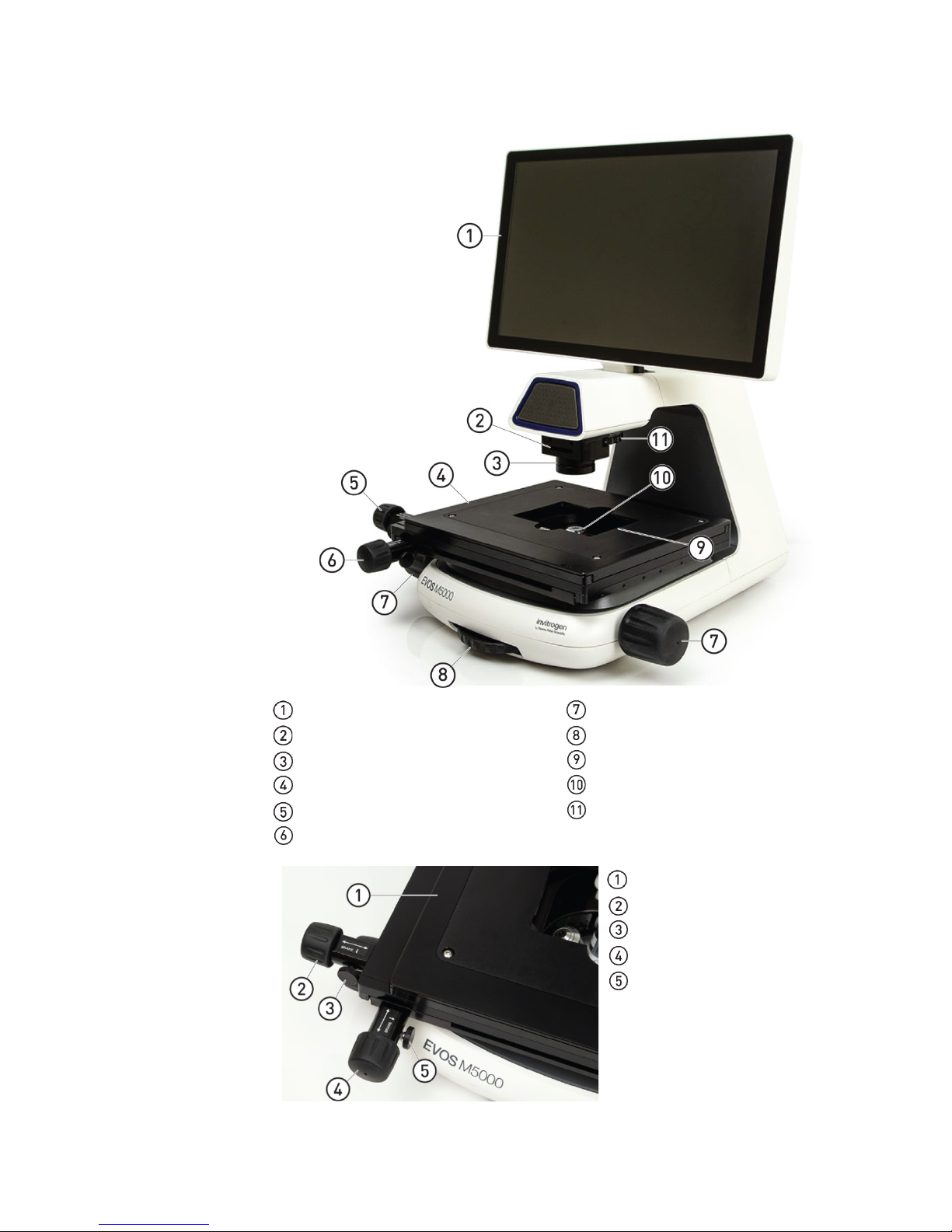
Front view
Stage positioning
Instrument exterior components and mechanical controls
knobs and brakes
LCD monitor Focusing knobs
Condenser slider slot Objective selection wheel
Condenser head Vessel holder
Mechanical X-Y stage Objective
Stage X-axis positioning knob Phase annuli selector
Stage Y-axis positioning knob
Mechanical X-Y stage
Stage X-axis positioning knob
Stage brake for X-axis
Stage Y-axis positioning knob
Stage brake for Y-axis
6
EVOS™ M5000 User Guide
Page 9
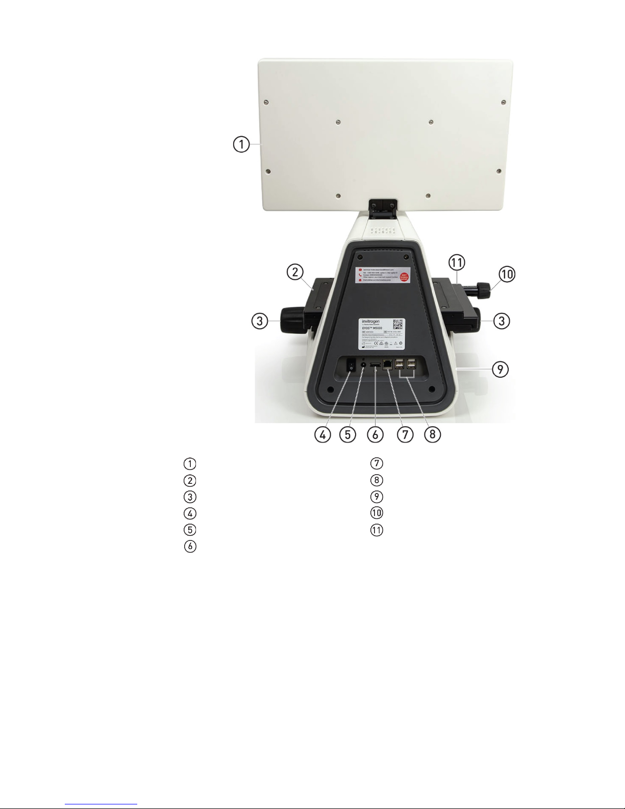
Rear view
LCD monitor Network port
Mechanical X-Y stage USB-A 2.0 ports (4×)
Focusing knobs USB 3.0 port (1×)
Power switch Stage X-axis positioning knob
4-pin power input port (12 VDC, 5 A) Stage Y-axis positioning knob*
Display port (video output) * Not visible in this perspective.
EVOS™ M5000 User Guide
7
Page 10
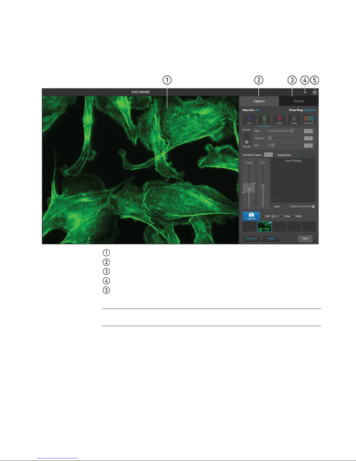
GUI layout
The GUI of the system consists of the Viewing area on the left and Capture and
and button opens the controls necessary to execute the selected function.
Graphical user interface (GUI)
Review tabs and the Settings and Virtual keyboard buttons on the right. Each tab
Viewing area: Displays the sample.
Capture tab: Contains the controls for image capture.
Review tab: Allows you to review and annotate captured images.
Keyboard button: Opens the virtual keyboard.
Settings button: Opens the Settings tabs, which allow you to select and adjust basic
and advanced system settings.
Note: For more information and detailed descriptions of GUI controls, see
“Appendix B: Graphical user interface (GUI)”, page 66.
8
EVOS™ M5000 User Guide
Page 11

2. Installation
• The dimensions of the EVOS™ M5000 Imaging System are 18 × 23 × 18 in
vibrations from other pieces of equipment. Tabletop centrifuges, vortex mixers,
• Electrical input: 12 VDC, 5 A
Hood setup
Operating environment and site requirements
(W×H×D) (46 × 59 × 46 cm). The system requires a benchtop of approximately
36 × 36 in (92 ×92 cm).
• If the system includes the optional EVOS™ Onstage Incubator (Cat. No.
AMC1000), then add 16 in (40 cm) to the width of the bench.
• Allow at least 5 cm (2 in) free space at the back of the instrument to allow for
proper ventilation and prevent overheating of electronic components.
• Place the EVOS™ M5000 Imaging System on a level surface away from
and other laboratory equipment can vibrate the instrument during a run and
cause a decrease in instrument performance.
• The EVOS™ M5000 Imaging System should be installed away from direct light
sources such as windows. Ambient light can enter the imaging path and affect
the image quality.
• Operating temperature range: 4°–32°C (40°–90°F).
• Relative humidity range: 0–90%.
• Operating power: 100–240 VAC, 1.8 A
• Frequency: 50–60 Hz
IMPORTANT! Do not position the instrument so that it is difficult to turn off the
main power switch located on the back of the instrument base (see page 7). In case
of an instrument malfunction, turn the main power switch to the OFF position and
disconnect the instrument from the wall outlet.
The EVOS™ M5000 Imaging System fits in cell culture hoods that are at least 24 in
(61 cm) deep and 36 in (92 cm) high with a 30 in (76 cm) opening. If your cell
culture hood is smaller, it may be possible to fit the instrument by turning it at a
slight angle.
EVOS™ M5000 User Guide
9
Page 12

Receive and inspect
1. Verify that the items shown on the shipping list are the same items that you
mishandling on the shipping documents.
Move the
installation site
1. Clear the installation site of all unnecessary materials.
Unpack the
1. Open the shipping box and remove the accessory box.
list of standard items included in the shipment.
Prepare for installation
the shipment
instrument to the
ordered at the time of purchase.
2. Carefully inspect the shipping containers and report any damage to the
Thermo Fisher Scientific service representative. Record any damage or
2. If possible, move the crated instrument and other shipping containers to the
installation site.
CAUTION! PHYSICAL INJURY HAZARD. Lift or move the instrument using
proper lifting techniques. We recommend that you lift or move the crated
instrument with the assistance of others and the use of appropriate moving
equipment. Improper lifting can cause painful and permanent back injury.
Depending on the weight, moving or lifting an instrument may require
two or more persons.
Install the instrument
instrument
2. Carefully lift the instrument out of the box by grasping it firmly with both
hands under the support arm.
3. Place the instrument on a flat, level surface that will be free from vibration and
leave enough room around it for the stage to move freely.
4. Tilt the LCD monitor upright.
5. Examine the instrument carefully for damage incurred during transit.
6. Unpack the accessories box and verify all parts are present. See page 5
for the
IMPORTANT! Do not subject the EVOS™ M5000 Imaging System to sudden impact
or excessive vibration. Handle the instrument with care to prevent damage.
Note: Contact your distributor if anything is missing. If you do not have your
distributor information, contact Technical Support (page 86). Damage claims must
be filed with the carrier; the warranty does not cover in-transit damage.
Note: Make sure to set aside packaging and foam for future transport and storage.
Re-install the stage lock pin and the light cube shipping restraint before moving
or transporting the instrument. Always ensure that the instrument is properly
cushioned and braced to prevent damage.
10
EVOS™ M5000 User Guide
Page 13
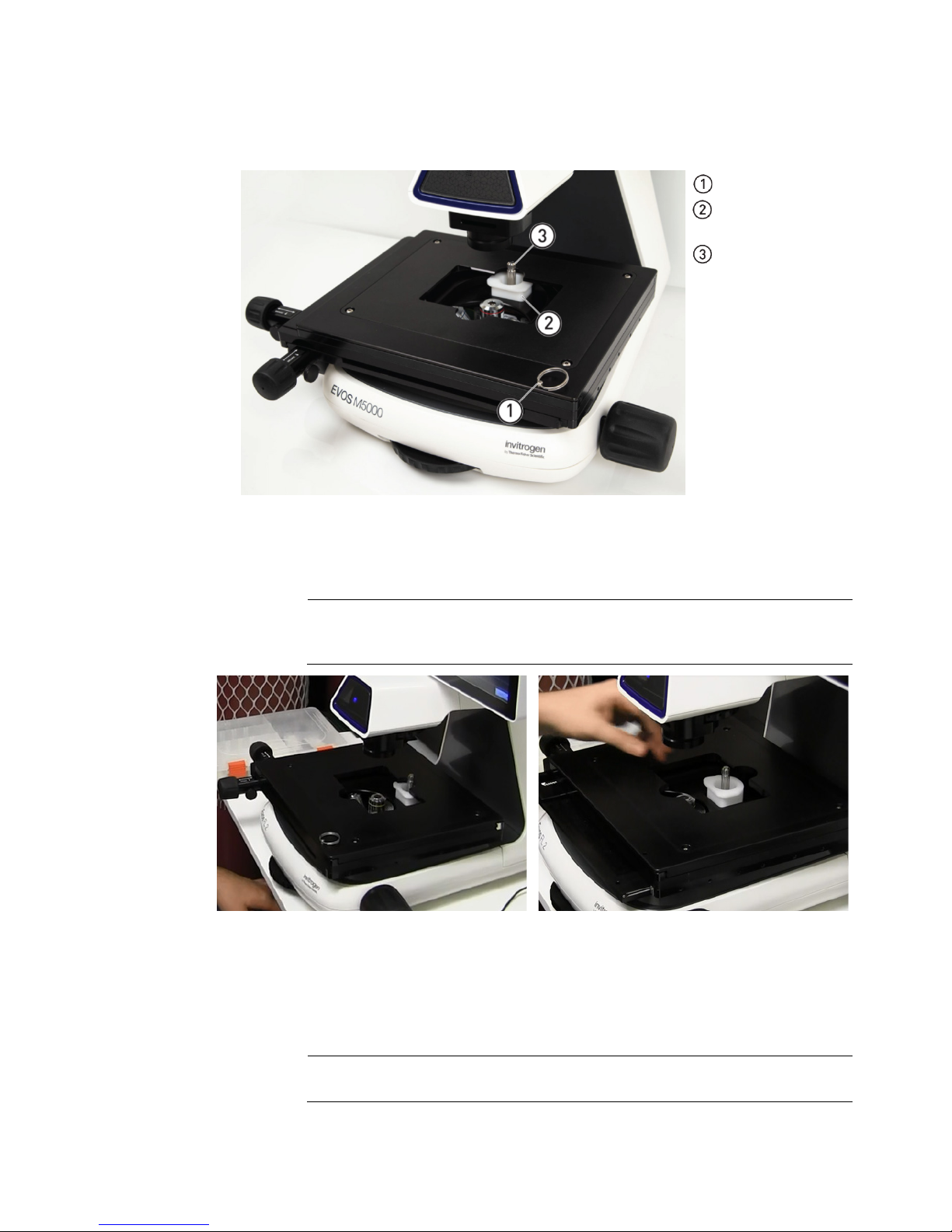
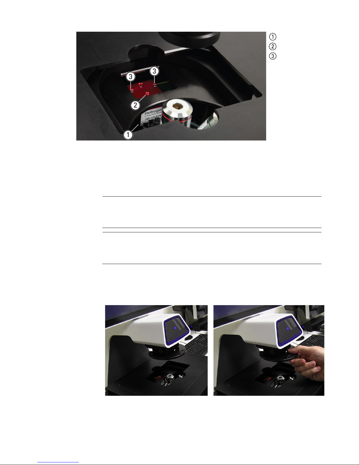
Remove shipping
The EVOS™ M5000 Imaging System is equipped with two shipping restraints
before you power on the EVOS™ M5000 Imaging System.
1. Pull firmly to remove the stage lock pin and release the X- and Y-axis brakes.
back of the stage.
Before stage reposition
After stage reposition
3. Unscrew and remove the light cube tool, which secures the shipping restraint
light cube turret.
restraints
(stage lock pin and light cube shipping restraint) to protect the instrument from
shock and vibration during transport. You must remove the shipping restraints
Stage lock pin
Light cube shipping
restraint
Light cube tool
2. Using the X-axis and Y-axis stage positioning knobs, move the stage back to
obtain access to the light cube shipping restraint, which is centered under the
Note: The light cube shipping restraint is secured with the light cube tool to
the blank light cube installed in the light cube turret. Used together, they
immobilize the light cube turret to protect it during transport.
block to the blank light cube.
4. Remove the shipping restraint block and store it in the accessories box.
Removal of the restraint block provides access to the blank light cube in the
Note: The blank light cube is red and does not have the grooved copper top
of the LED light cubes.
EVOS™ M5000 User Guide
11
Page 14
5. Using the light cube tool, loosen the two screws that secure the blank light cube
7. Place the desired EVOS™ Vessel Holder on the stage.
Install the UV light
1. Verify that the EVOS™ Condenser Light Shield is installed on the condenser
Blank light cube
Thread hold
Screws
to the instrument. You do not need to remove the screws.
6. Screw the light cube tool to the thread hold on the light cube, then lift the blank
light cube up and out of the light cube turret. Store the blank light cube and the
light cube tool in the accessories box.
Note: Store the shipping restraints and the light cube tool for future use in the
accessories box provided with your system. Always re-secure the X-Y stage with
the stage lock pin and re-install the light cube restraint before moving the
instrument.
IMPORTANT! Before changing light channels, ALWAYS verify the light cube
restraint has been removed. Attempting to change the light channels while the
restraint is in place can seriously damage the mechanism. This type of damage is
not covered by manufacturer’s warranty.
shield
assembly. The condenser shield is pre-installed and helps reduce the potential
effects of overhead lighting on your image.
2. Pull the condenser light shield out from the condenser head.
12
EVOS™ M5000 User Guide
Page 15
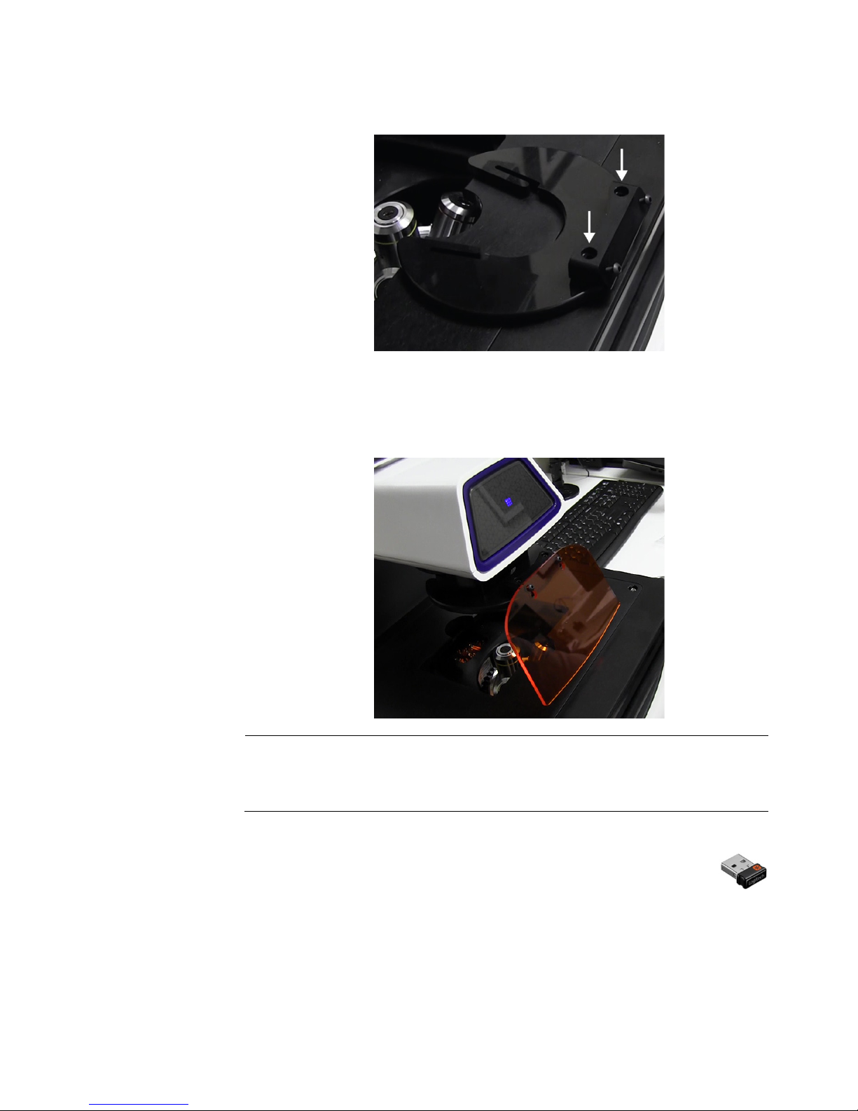
3. Secure the UV light shield mount to the top of the condenser light shield using
the two screws supplied with the UV shield assembly (not the protruding
Connect the
1. Confirm that the power switch is OFF (located on the back; see page 7).
supply.
screws on the mount).
4. Clip the condenser light shield with the attached UV light shield mount back
onto the condenser head.
5. Peel the protective paper from the UV light shield, then slide the orange UV
light shield over the two protruding screws on light shield mount to attach it
to the instrument.
Note: The UV light shield is provided as a safety feature and should be installed
whenever the unit is in operation. The UV light shield is removable for access to
the condenser sliders used in transmitted light mode. Simply unhook it from the
screws on the UV light shield mount.
instrument
2. Connect the USB receiver for the wireless mouse and keyboard to an
available USB-A 2.0 port (page 7).
3. Connect the power adaptor and power cord. Ensure a tight connection
4. Plug the power adaptor into the power input port on the instrument (page 7).
5. Plug the power cord into a power outlet and check for the light on the power
EVOS™ M5000 User Guide
13
Page 16
Power ON the
1. Turn the instrument power switch (located on the back; see page 7) to the ON
Connect to a Wi-Fi
network
For instructions on how to connect to a Wi-Fi network and how to map a network
EVOS™ M5000
Imaging System
position.
2. When the Capture tab is displayed, the EVOS™ M5000 Imaging System is
ready to use.
IMPORTANT! All shipping restraints must be removed before turning on the
™
EVOS
M5000 Imaging System to prevent damage (page 11).
drive to save your images, see “Configure network settings”, page 56.
14
EVOS™ M5000 User Guide
Page 17
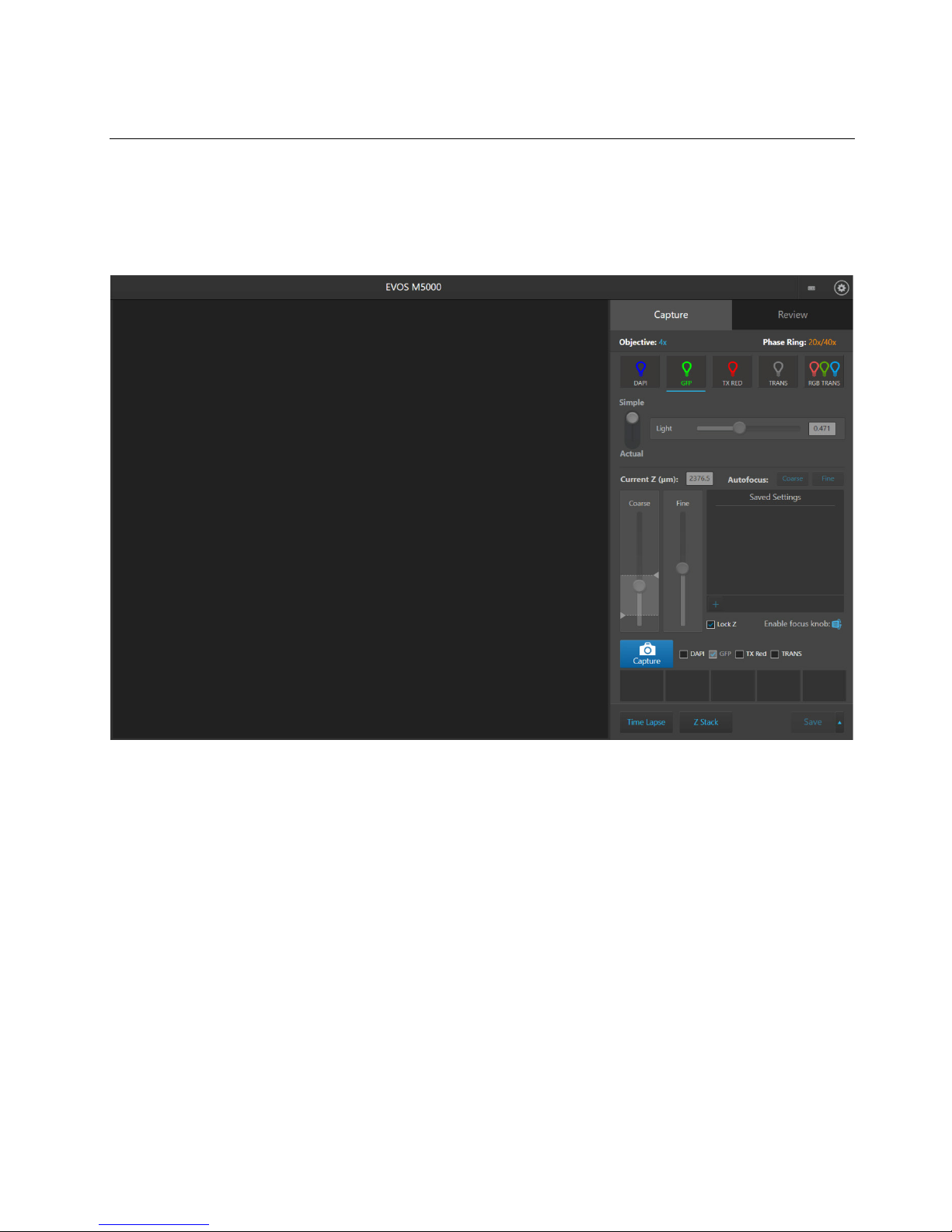
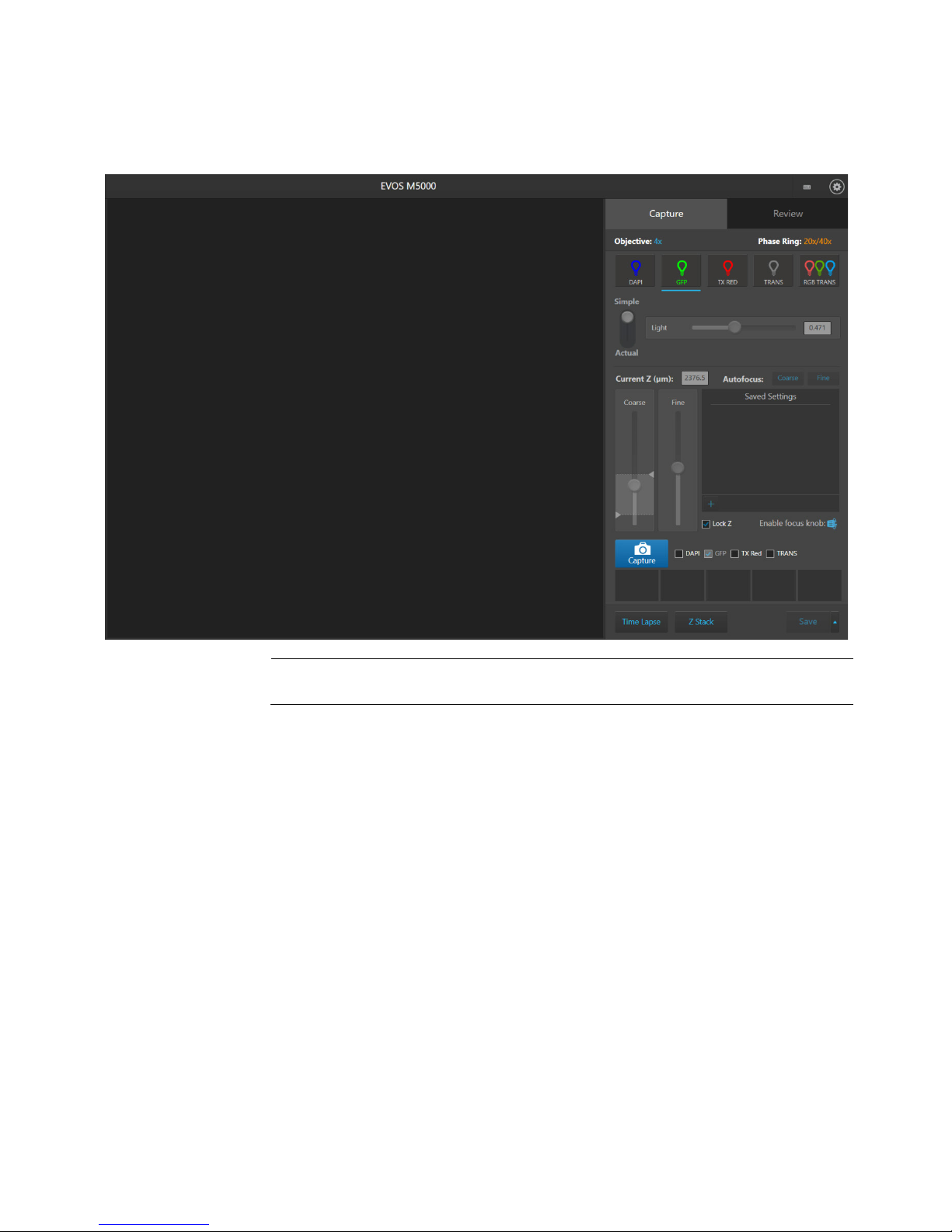
3. Capture images
Capture tab
The basic functions of the EVOS™ M5000 Imaging System, such as viewing the
Workflow
Select objective and light source
Adjust brightness
Focus on the sample
Find the region of interest
Capture image in a single channel
Analyze and annotate captured images
Show cell count
Save
Overview
sample, setting optimal focus, and capturing and saving images are performed in
the Capture tab, which is the first screen after start-up.
EVOS™ M5000 User Guide
15
Page 18
Select objective and
1. Place the vessel containing your sample on the stage using the appropriate
2. Set the magnification using the objective selection wheel (page 6).
Capture images
light source
vessel holder.
Note: When capturing images in fluorescence channels, place the light shield
box on the stage, over the sample. This is important for optimal image quality.
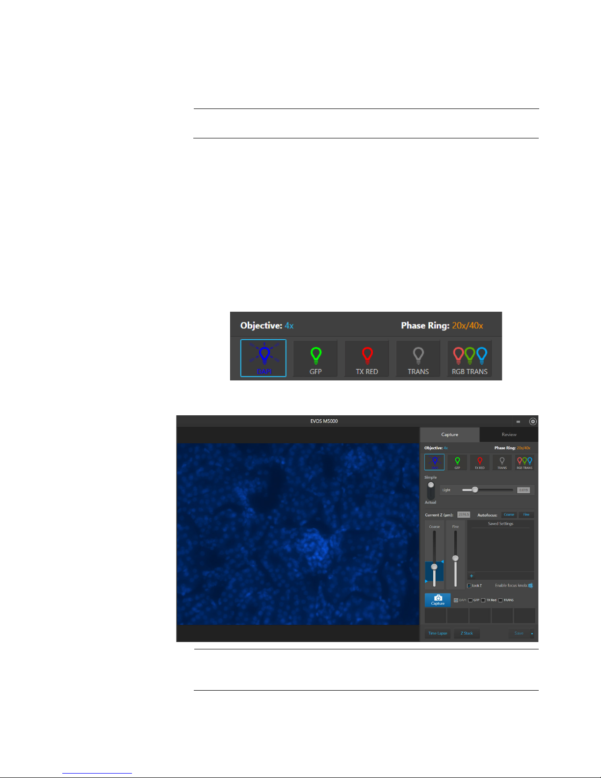
3. Select the desired Phase option by turning the phase annuli selector (page 6).
Available options are:
• Oly 4×: Used for low magnification objectives (Olympus
• 4×/10×: Used for medium magnification objectives (EVOS
• 20×/40×: Used for high magnification objectives (EVOS
• Brightfield (phase contrast off)
The active objective and phase ring information is displayed above the
Channel buttons.
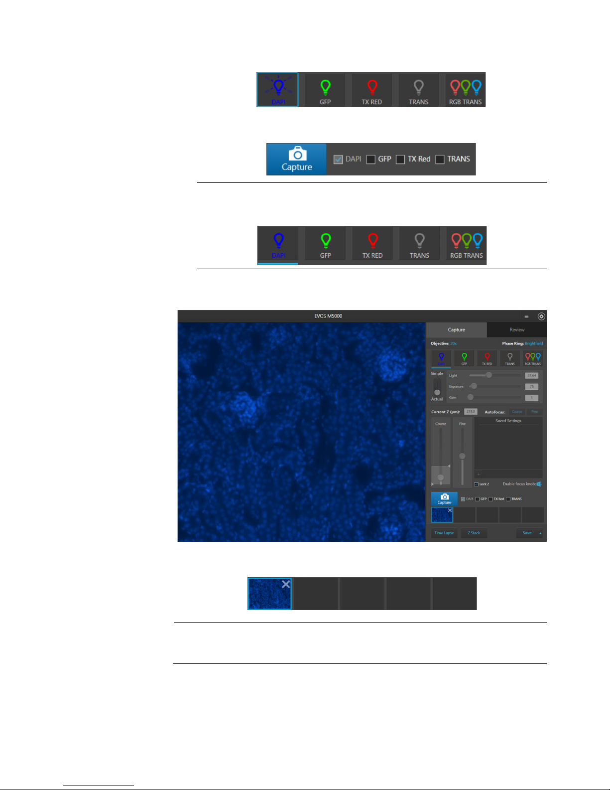
4. Select a Channel to turn on the excitation light and enter the instrument in the
Live mode. In this example, the DAPI channel has been selected.
In the Live mode, you can adjust the brightness and configure display settings
for the selected channel, and set the focus on the sample.
™
4× PH)
™
4×/10× PH)
™
20×/40× PH)
Note: You can select only one light source at a time for Live mode to adjust
brightness and set focus. However, you can display and capture multiple
channels simultaneously.
16
EVOS™ M5000 User Guide
Page 19
Adjust brightness
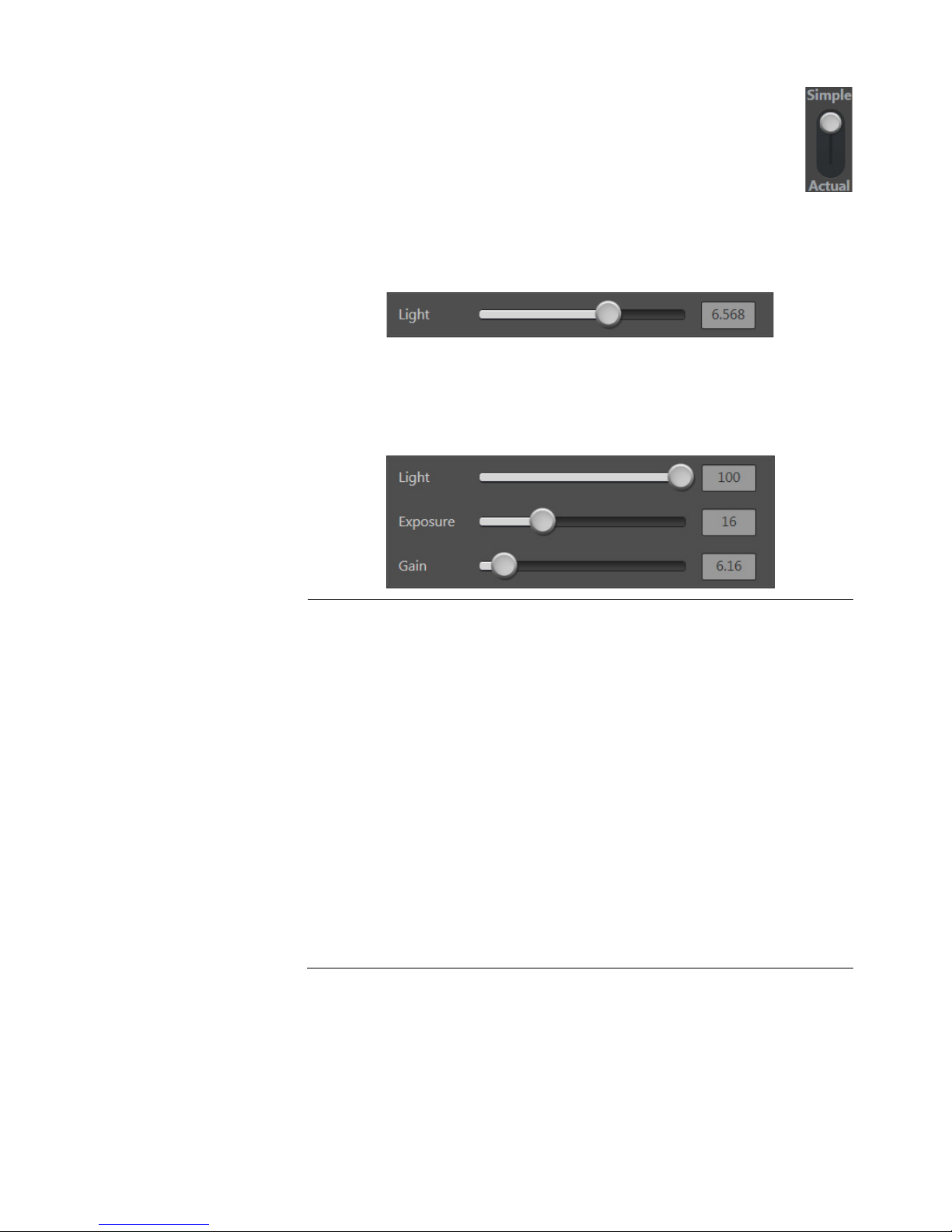
1. For Brightness mode, select Simple or Actual.
- Simple mode allows you to control Brightness as a single
•
parameter.
- Actual mode allows you to adjust Light (i.e., LED intensity),
Exposure, and Gain parameters individually.
2. Adjust brightness using the Brightness controls:
• In the Simple mode, move the Light slider to adjust brightness.
Alternatively, enter the desired brightness value (0%−100%) directly in the
brightness field.
In the Actual mode, move the Light (LED intensity), Exposure, and Gain
sliders to adjust the brightness parameters individually.
Alternatively, enter the desired value for each parameter (0%−100% for
Light, 0−4.00 seconds for Exposure, or 1.0−8.0 for Gain) directly in the
corresponding field.
Note: Optimize the brightness parameters as follows:
• When searching for sample: Increase Gain for a brighter signal and
decrease Exposure for faster frame rate during navigation around the
vessel.
• When capturing image: Decrease Gain to reduce background noise and
increase Exposure to regain signal intensity, as needed.
• For brighter signal: Increase Light intensity for brighter illumination. If
needed, follow by increasing Gain.
• For time lapse imaging: Increase Gain and Exposure, and decrease
Light intensity to reduce photobleaching and phototoxicity.
For example, for overnight time lapse experiments, capture one image
every 30 minutes or less, limit the use of autofocus, and use a channel
other than DAPI for autofocus.
• In the Settings Visuals tab, select Highlight Saturated Pixel to display
the overexposed pixels in the color of your choice. To obtain the
maximum level of brightness without any overexposed areas, dim the
illumination until the highlights disappear.
EVOS™ M5000 User Guide
17
Page 20
Focus on the
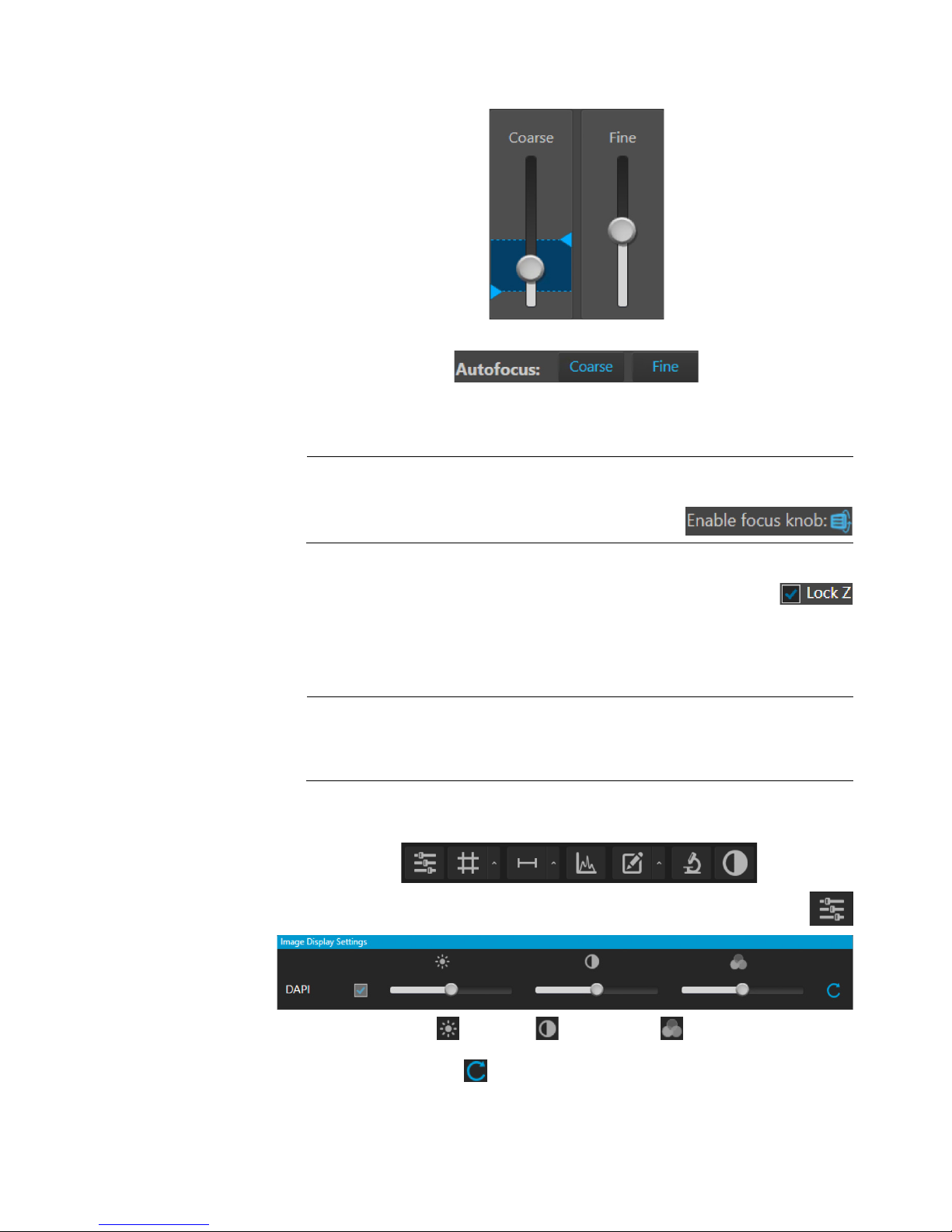
1. Use the Coarse and Fine focus sliders to focus on the sample.
the Coarse focus slider) to set the upper and lower bounds.
3. Repeat the focus procedure for each channel you want to capture.
• When unlocked, only the current channel is affected.
Optional
: Configure
1. Hover the pointer over the Viewing area to reveal the buttons for Display
5. Click the Image Display Settings button again to collapse the controls.
sample
Alternatively, click Coarse and Fine autofocus to autofocus on the sample.
2. To limit the autofocus algorithm to a specific region along the Z-axis, use the
Autofocus Maximum and Autofocus Minimum controls (blue triangles on
Note: You can also focus on the sample manually using the focusing knobs
on the instrument (page 6).
Click Enable focus knob, then turn the focusing
knob until the region of interest is in focus.
4. If you want to preserve the Z-Offsets between the channels, select
Lock Z.
• When locked, the movement of the Z-axis in one channel affects all
channels.
Note: Z-Offsets specify the optimal focus position in a channel relative to the
focus position in other channels. Setting the correct Z-Offsets is especially
important when the fluorescent markers in different channels are in different
focal planes.
display settings
Settings and Analysis Tools.
2. Click Image Display Settings button to expand the controls for image
display parameters for the selected channel.
3. Adjust Brightness , Contrast , and Gamma with the corresponding
sliders.
4. Click the Reset button to return the display settings to their default values.
18
EVOS™ M5000 User Guide
Page 21
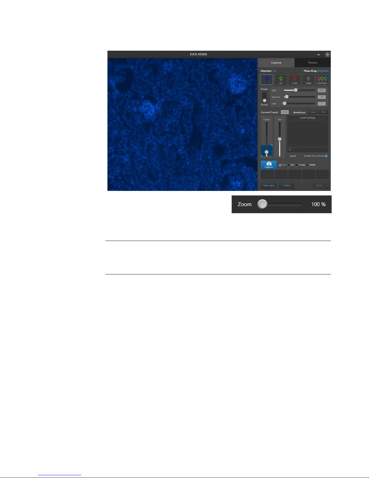
Find the region of
1. Use the X-axis and Y-axis positioning knobs (page 6) to move the sample stage
2. To zoom in and out of the Viewing area,
image.
interest
and bring the region of interest into the field of view.
use the Zoom slider. The zoom range is
100% to 1000%.
3. If needed, re-adjust the brightness and focus, then proceed to capture the
Note: If desired, enable Quick Save (page 35) before proceeding to image capture.
Quick Save function allows you to set the save options in advance and save your
captured images with a single click directly from the Capture tab or automatically
after each capture.
EVOS™ M5000 User Guide
19
Page 22
Capture image in a
1. Ensure that the Channel you want to capture is selected.
2. Click Capture to acquire the image.
single channel
When you select a Channel, the corresponding Capture channel box is
automatically checked.
Note: If you have exited the Live mode by clicking the Channel button again,
the current channel remains selected, as indicated by the blue line
underneath the corresponding channel button.
The viewing area shows the newly captured image.
A thumbnail of the captured image is displayed for the selected channel (in this
example, DAPI).
IMPORTANT! Captured images are stored in the memory buffer. If unsaved, newly
captured images overwrite the previously captured image in the selected channel.
Images captured in other fields and channels are not affected.
20
EVOS™ M5000 User Guide
Page 23
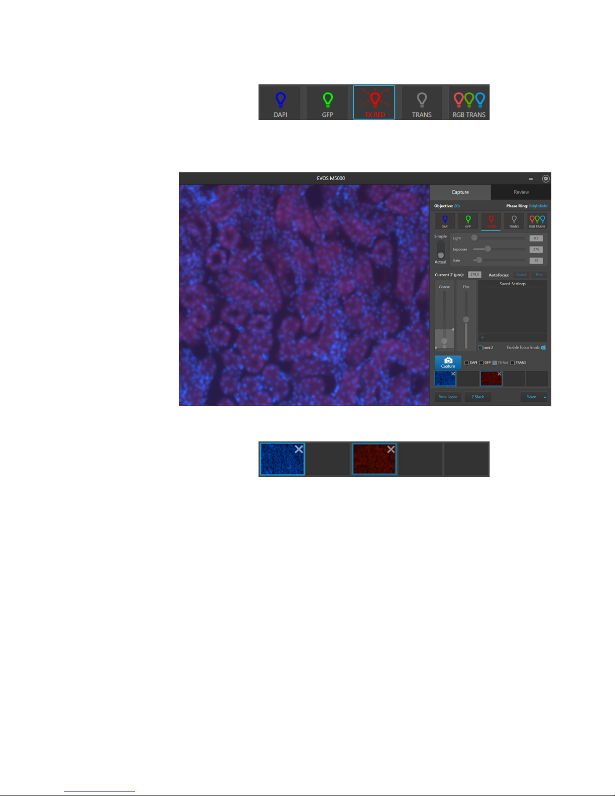
3. To capture the same field of view in another channel, select the desired
Channel.
4. If needed, re-adjust the brightness and focus, then click Capture.
The viewing area shows the image captured in the new channel superimposed
on the image captured in the previous channel.
A thumbnail of the image captured in the new channel is displayed along with
the thumbnail of the image from the previously captured channel.
EVOS™ M5000 User Guide
21
Page 24
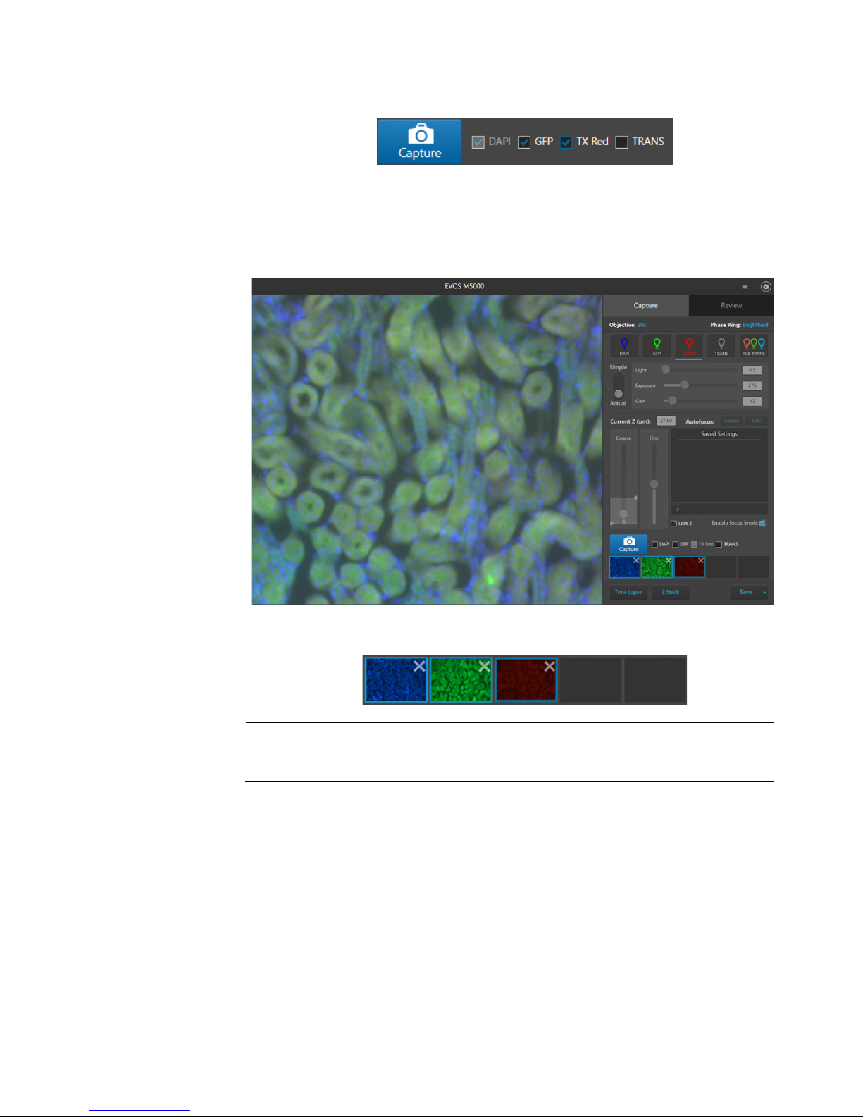
Capture multiple
1. To capture multiple channels simultaneously, select the desired channels by
channels
checking corresponding boxes.
simultaneously
2. If needed, adjust brightness and focus for each of the selected channels as
described.
3. Click Capture to acquire an image in each of the selected channels.
The Viewing area shows a multicolor overlay of the images captured in each
selected channel.
A thumbnail of the captured image is displayed for each selected channel (in
this example, DAPI, GFP, and Texas Red).
IMPORTANT! Captured images are stored in the memory buffer. If unsaved, newly
captured images overwrite the previously captured image in the selected channel.
Images captured in other fields and channels are not affected.
22
EVOS™ M5000 User Guide
Page 25
Analyze and annotate captured images
Display settings
Display settings and analysis tools allow you to change image display settings for
2. Click a button to open the corresponding tool; click the button again to close it.
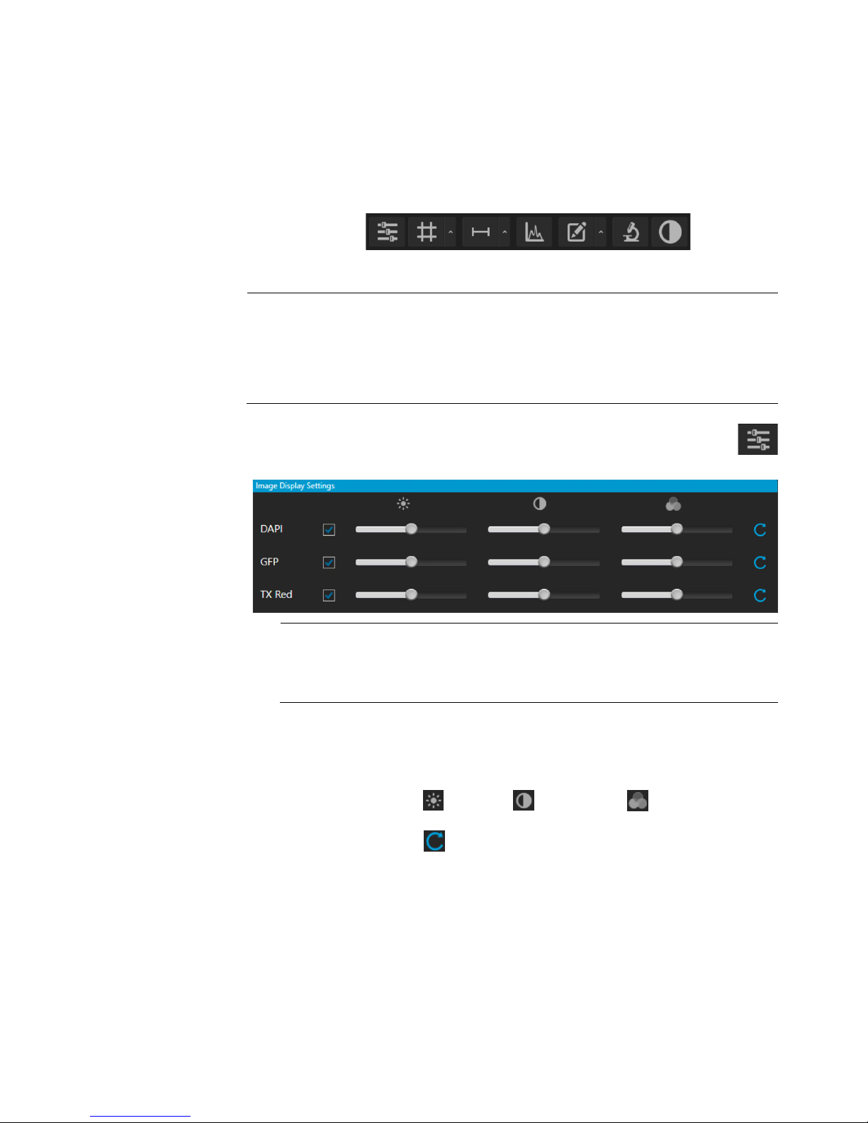
Configure display
1. Click the Image Display Settings button to expand the controls for
or for a single channel in the
2. Optional: To remove a channel from displaying in the Viewing Area, unselect
5. Click the Image Display settings button again to collapse the controls.
and analysis tools
settings
live and captured images in the Viewing area, and to analyze and annotate
captured images.
1. Hover the pointer over the Viewing area to reveal the buttons for Display
Settings and Analysis Tools.
IMPORTANT! Changes made to images in the Viewing area with the display
settings and analysis tools, including changes made to image parameters, display
of the grid and the scale bar, as well as any annotations and measurements, persist
when the images are saved. If you want to save raw image data that you can use
for analysis, make sure to select Save individual channels option when saving
captured images (see page 34).
image display parameters (brightness, contrast, gamma) for captured
images.
Note: The controls for image display settings are contextual; they are
available only for channels with captured images
Live mode (with the excitation light turned on). In the example above, only
the controls for DAPI, GFP, and TX Red channels are displayed.
the corresponding checkbox.
To display a channel with a captured image that is not shown in the Viewing
Area, re-select the checkbox.
3. Adjust the Brightness , Contrast , and Gamma settings for each of
the selected channels using the corresponding sliders.
4. Click the Reset button to return the image display settings to their default
values.
EVOS™ M5000 User Guide
23
Page 26
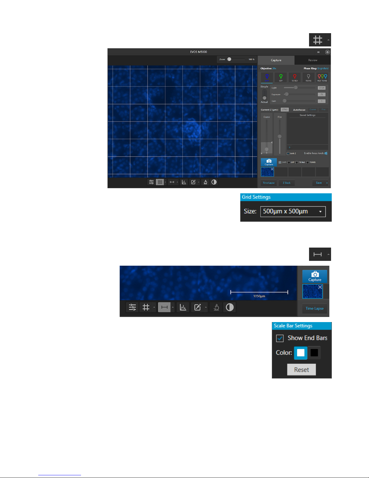
Display grid
1. Click the Grid button to superimpose a grid over the Viewing area.
4. Click the Grid Settings button again to save your settings and close the tool.
Display scale bar
1. Click the Scale Bar button to superimpose a scale bar over the
settings and close the tool.
2. To change the grid size, click the Grid
Settings button (the arrow on the Grid split
button) to open the Grid Settings tool.
3. Select the Size for the grid:
200 µm× 200 µm or 500 µm× 500 µm.
Viewing area.
2. To change scale bar settings, click the Scale Bar
Settings button (the arrow on the Scale Bar split
button) to open the Grid Settings tool.
3. Select Show End Bars to display the scale bar with the
end bars.
4. Select the Color for the scale bar.
5. Click the Scale Bar Settings button again to save your
24
EVOS™ M5000 User Guide
Page 27
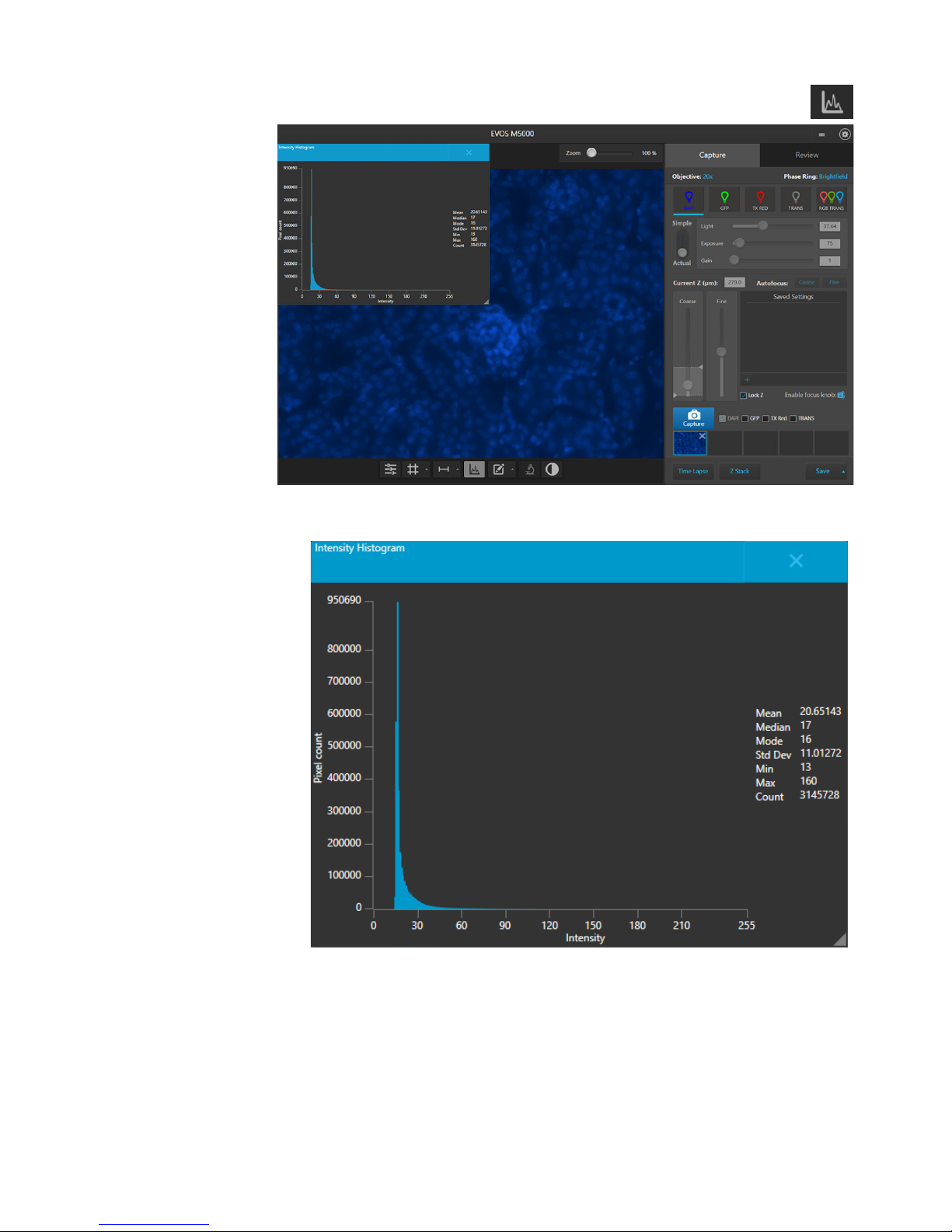
Display histogram
1. Click the Histogram button to open the Intensity Histogram plot.
You can also close to plot by clicking the X on the plot.
2. Intensity Histogram plot shows the Pixel count vs. Intensity data of the image
displayed in the Viewing area.
3. Click the Histogram button again to close the Intensity Histogram plot.
EVOS™ M5000 User Guide
25
Page 28

Add and show
1. Click the Measurement and Annotations Tools button (the arrow on
split button) to turn the display on and off.
measurements and
annotations
the Show Measurements and Annotations split button) to open the
measurement and annotations tools.
2. Using the Draw… tools, draw a rectangle, ellipse, polygon, line, or a free-
form shape over the region of interest on the Viewing area. You can draw
multiple shapes of different type.
3. If needed, change the Color and Thickness of the annotation to make it more
visible over the image. You can select a different color and thickness for each
annotation.
4. If desired, select to display the Dimensions, Area, or Perimeter information for
the annotation from the dropdown menu.
5. To delete a selected annotation, click the Delete this annotation button.
To delete all annotations, click the Delete All button.
6. Click the Measurement and Annotations Tools button again to close the tools.
7. Click the Show Measurements and Annotations button (the main part of the
26
EVOS™ M5000 User Guide
Page 29

Show cell count
Show Cell Count
Show Cell Count function allows you to count objects in captured or saved images.
multiple channels simultaneously, provided that they contain images.
Run Auto Count
1. Click the Show Cell Count button, then select Auto Count.
function
Hover the pointer over the Viewing area to reveal Display Settings and Analysis
Tools, then click the Show Cell Count button to display Auto Count and Manual
Count options in the tabs area.
• Auto Count: Automatically counts the objects displayed in the Viewing area
based on your specifications (page 27). With Auto Count, you can count objects
only in a single channel.
• Manual Count: Allows you to tag objects in the Viewing area with up to six labels.
As you tag objects, the system keeps a running tally of the counts with percentages
for each label assigned (page 31
Note: You can access Show Cell Count from either the Capture or the Review tab.
). With Manual Count, you can count objects in
2. Select the Channel in which to count objects.
Available options depend on the LED light cubes installed, and you can only
select channels that contain captured images. In this example, only DAPI and
TX Red channels contain captured images, and DAPI is selected for auto count.
EVOS™ M5000 User Guide
27
Page 30

3. To identify the target objects to include in your count,
4. If needed, click Target again to identify further objects to include in your count
background objects that might affect your count results.
click Target, then click and drag to draw a circle (green)
around a representative target.
Note: For best results, follow these guidelines when identifying target objects:
• When selecting objects, circle the entire object and include a slight border
around it.
• To include objects of lower intensity in your count, select dimmer objects
during identification.
• Circle only one object at a time to help define object size for segmentation.
(for example, targets that might appear different).
5. To distinguish the target from the background, click
Backround, then click and drag to draw a circle (red) in
a background area.
6. If needed, click Background again to identify other background areas or
28
EVOS™ M5000 User Guide
Page 31

7. To count closely grouped objects that are touching or overlapping as distinct
objects, select from the Split Cells options:
dropdown.
- None: Touching or overlapping objects are not counted separately.
- Shape: Distinct objects are identified based on shape.
- Intensity: Distinct objects are identified based on intensity.
8. When you are finished defining the target and background areas, the software
automatically counts the objects based on your examples.
Object Count field displays the number of objects included in the count.
Viewing area identifies the objects that were counted with a colored circles.
9. To change the color of the circles that identify the objects
included in the count, select the desired color from the
Count Color
EVOS™ M5000 User Guide
29
Page 32

10. The Refine section displays a histogram plot showing Count versus Intensity,
results”, page 33).
Area, or Circularity. In this example, Intensity is selected.
11. To refine your count, select Intensity, Area, or Circularity, then move the
handles of the gate bars in the desired direction to set the upper or the lower
boundary for the selected parameter.
The software applies the selected boundaries and recalculates the count.
12. When finished with the count, save your count results (see “Save count
IMPORTANT! If you navigate away from the Auto Count screen, your count will
be lost. To preserve the count results, make sure to save it before you navigate
away from the count screen.
30
EVOS™ M5000 User Guide
Page 33

Perform Manual
Count
1. Click the Show Cell Count button, then select Manual Count.
2. Select the Channels to display in the Viewing area for manual count. You can
select multiple channels, provided that they contain captured images.
In this example, only DAPI and TX Red channels contain captured images, and
both are selected for the manual count.
3. Click in a Label field to enter a name for that label. You can use up to six labels
to tag objects for the manual count.
EVOS™ M5000 User Guide
31
Page 34

4. Click on the Label number to select a label, then left-click at each point
5. To delete all tags for a label, click the Delete button for that label
(see “Save count results”, page 33).
on the Viewing area to tag the items in that label category. You can
switch labels as desired.
As you tag the objects onscreen with the selected label, the system keeps a
running tally of the counts with percentages for each label assigned.
category.
6. To delete all tags for all labels, click the Delete All button.
7. When finished with the count, save your count results
32
EVOS™ M5000 User Guide
Page 35

Save count results
1. When finished with your auto or manual count, click Save to open the Save
Composite Image dialog, then navigate to the folder where you want to save
the labels, counts, and percentages
your count results.
2. Select Save as screenshot to preserve a detailed
account of your count results as an image.
• For Auto Count, the screenshot shows the count histogram and the
selections made in the Auto Count tool.
• For Manual Count, the screenshot shows
as shown in the Manual Count tool.
• Deselecting the Save as screenshot option for Auto or the Manual Count
produces an image saved with the tags and the total count information only.
3. Click Save to save your count results and close the dialog.
EVOS™ M5000 User Guide
33
Page 36

Save images
1. After capturing an image in a single channel or a set of images in multiple
option unselected to save only the captured
Leave the Save screenshot option unselected to save only the captured image.
4. Enter a new file name for your saved images or use the default file name, then
5. Click
to save the image.
4. Save captured images
Save
manually
channels, click Save to open the Save dialog, then navigate to the folder where
you want to save your captured images.
2. Select Save individual channels to save images captured in
different channels individually. This is the recommended
format for image analysis.
Leave the Save individual channels
image displayed in viewing area.
3. Select Save screenshot to save an image of the entire
instrument screen in addition to the captured image.
34
Note: Save screenshot function allows you retain an image of the annotations
and image display selections as seen in the viewing area along with the
instrument controls.
select the file format from the Save as type dropdown.
Available file formats are BMP, JPG, PNG, and TIFF.
Save
IMPORTANT! Save individual channels is the recommended format for image
analysis, because it allows you to save raw image data from each selected channel.
EVOS™ M5000 User Guide
Page 37

Quick Save images
Optional
: Enable
Quick Save function allows you to set the save options in advance and save your
4. Enter a Base Filename and Count.
5. Select the File Type from the dropdown menu. Available options for file type
dialog.
Quick Save
captured images with a single click directly from the Capture tab or automatically
without having to click Save after each capture.
1. Click the Quick Save Settings button (the arrow on the Save
split button) to open the Quick Save Settings dialog.
2. Select Enable Quick Save.
3. Click the Save Folder button to open the Select Folder dialog, go to the
folder where you want to save captured images, then click Select Folder.
Note: The default base filename is Image. Base filename is appended by a
numerical suffix and channel name.
Count determines the starting numerical suffix, which is increased by one for
each subsequently saved image. For example, Image_0001, Image_0002, and
so on.
are PNG, TIFF, JPEG, and BMP.
6. To save the image displayed in the viewing area and each underlying channel
individually, select Save underlying channels.
7. To save captured images automatically without having to click Save after each
capture, select Save on each capture.
8. Click the Quick Save Settings button again to save your settings and close the
EVOS™ M5000 User Guide
35
Page 38

With the Time Lapse tool, you can set up your cells and program the EVOS™ M5000
can be saved, recalled, even edited.
Run a new time
1. On the Capture tab, click Time Lapse to open the Time Lapse tool.
channel (either Auto Focus as part of the routine or initial focus positions).
5. Capture and save time lapse images
Time Lapse tool
Imaging System to capture images (including Z-Stack images) at given intervals over a
time period based on your specifications. For repeat experiments, time lapse routines
Run a time lapse routine
lapse routine
2. Select the Capture Channels for time lapse images. You can select multiple
channels. In this example, DAPI and GFP channels have been selected.
3. Select Auto Focus to run the autofocus algorithm during the
time lapse routine.
Unselect Auto Focus to capture time lapse images using the initial focus
positions set before you run the routine.
4. Select Z-Stack to capture multiple images along the Z-axis
based on your specifications.
Unselect Z-Stack to capture images only at the focus position set for each
36
EVOS™ M5000 User Guide
Page 39

5. Adjust brightness and focus for each selected channel as described in “Capture
images” (page 16), then click Next.
)
6. If you have opted to run Auto Focus, select the Auto Focus Channel to use.
7. Select to autofocus at Every interval or at
Note: When the sample is focused and ready, tighten the stage brakes (page 6
to prevent the stage from drifting during the time lapse routine.
Note: In a time lapse routine, you can run the autofocus procedure only in a
single channel (in this example, DAPI). The focal plane identified in this
channel is then used for all other channels.
First interval of each run, then click Next.
Note: In a time lapse routine, images are captured at the end of each interval
of a run. For more information, see “Intervals”, page 39.
EVOS™ M5000 User Guide
37
Page 40

8. If you have opted to capture Z-Stack images, define the In Focus, Top, and
Bottom position (lower boundary of the Z-Stack), then click Set for Bottom.
9. Define the Z-Stack parameters to determine the number of “optical sections”
Stack
Bottom positions for the Z-Stack image set:
a. If not already on, click the Light button to illuminate the sample as you
locate the boundaries and the In Focus position of the Z-Stack.
b. To accept the Current Z as the In Focus position, click Set for In Focus.
To change the In Focus position, move the Coarse and Fine focus sliders
on the Capture tab to focus on the sample, then click Set.
c. Move the focus sliders up from the Current Z position to the desired Top
position (upper boundary of the Z-Stack), then click Set for Top.
d. Move the focus sliders down from the Current Z position to the desired
Note: Click the Z number button for the Top, In Focus, and Bottom positions
to jump to that position along the Z-axis.
captured in the Z-Stack image set:
• Automatically compute Z-Stack Parameters: Select to calculate the
number of images and their Z-positions automatically based on the Zboundaries and the default Step Size.
• Manually Set Step Size: Select to enter the Step Size (Z-distance in µm
between focal planes) in the corresponding text box. The system calculates
the number and Z-positions of the images based on your entry.
• Manually Set Number of Images: Select to enter the Number of Images
(Z-distance in µm between focal planes) in the corresponding text box.
The system calculates Step Size and the Z-positions of the images based on
your entry.
10. Select Generate Projection Image to generate a
projection image.
When selected, the system uses the most in-focus pixels from images captured
at different focal planes to generate a composite in-focus image. Each image in
the Z-Stack is also separately saved.
When unselected, the system only saves the individual Z-Stack images.
11. Click Next to proceed to create Run.
38
EVOS™ M5000 User Guide
Page 41

12. Enter the Total Time for Run 1 into the corresponding Hours, Minutes, and
Seconds fields. You can create multiple Runs for a Time Lapse Routine, each
13. Set the Image capture options for Run 1. Available options are:
exposure settings.
with its own duration and image capture frequency.
• Frequency: Enter the time period in Hours, Minutes, and Seconds that
must elapse before a new set of images are captured.
For example, in an experiment with an image capture frequency of
2 minutes and 30 seconds, the images will be captured every 2 minutes
and 30 seconds after the initial set of images are acquired at time point 0.
• Intervals: Enter the total number of time intervals between the captured
image sets for a given run duration.
Images are collected at the end of an interval. For example, in a Run
experiment with a duration of 5 minutes and 2 intervals, the images will
be captured every 2 minutes and 30 seconds after the initial set of images
are acquired at time point 0.
• As fast as possible: Select this option to capture a new set of images
immediately after completing the previous set without any delay between
the sets.
The speed with which the images are captured depends on the specific
choices made for the routine such as the autofocus frequency and
EVOS™ M5000 User Guide
39
Page 42

14. Optional: Click Add Run to add another Run to the Time
Lapse routine, then define the Run options as described for
Run 1.
15. When finished with adding Runs, click Next to proceed to Save options.
16. Click the Browse button to open Choose Save Folder dialog, go to the
destination folder for the Time Lapse images, then click Select Folder.
17. Select the File Type: PNG or TIFF.
40
EVOS™ M5000 User Guide
Page 43

18. Click Start to run the Time Lapse routine.
The system provides information about the progress of the
Time Lapse routine as it captures the images based on the
routine specifications.
19. When the Time Lapse routine is completed, the Review tab opens to the files
captured in the routine.
EVOS™ M5000 User Guide
41
Page 44

Run a saved time
Each time you run a Time Lapse routine, the system saves the specifics of the
5. Click Start to run the Time Lapse routine.
lapse routine
routine, which you can then recall and run with a new sample.
1. On the Capture tab, click Time Lapse to open the Time Lapse tool.
2. Click Load Routine to open the Choose Routine dialog.
3. Select the routine you want to run, then click Open.
4. If needed, make changes to the routine as described for new routines.
42
EVOS™ M5000 User Guide
Page 45

6. Capture Z-Stack
Z-Stack tool allows you to capture multiple images of a selected field at different
greater depth of field than any of the individual source images.
1. On the Capture tab, click Z Stack to open the Z-Stack tool.
Z-Stack tool
focal planes along the Z-axis and combine them to generate a final image with a
Capture Z-stack images
2. Select the Channels for Z Stack that you want to capture. You can select
multiple channels. In this example, DAPI and GFP channels have been
selected.
EVOS™ M5000 User Guide
43
Page 46

3. If not already on, click the Light button to illuminate the sample, then adjust
7. Define the Z-Stack parameters to determine the number of “optical sections”
Stack
brightness and focus using the corresponding sliders on the Capture tab.
The focus position you set in this step is the initial
Current Z position.
4. To accept the Current Z as the In Focus position, click Set for In Focus.
To change the In Focus position, move the Coarse and Fine focus sliders on
the Capture tab to focus on the sample, then click Set.
5. Move the focus sliders up from the Current Z position to the desired Top
position (upper boundary of the Z-Stack), then click Set for Top.
6. Move the focus sliders down from the Current Z position to the desired
Bottom position (lower boundary of the Z-Stack), then click Set for Bottom.
Note: You can click the Z number button for the Top, In Focus, and Bottom
positions to jump to those positions along the Z-axis.
captured in the Z-Stack image set:
• Automatically compute Z-Stack Parameters: Select to calculate the
number of images and their Z-positions automatically based on the Zboundaries and the default Step Size.
• Manually Set Step Size: Select to enter the Step Size (Z-distance in µm
between focal planes) in the corresponding text box. The system calculates
the number and Z-positions of the images based on your entry.
• Manually Set Number of Images: Select to enter the Number of Images
(Z-distance in µm between focal planes) in the corresponding text box. The
system calculates Step Size and the Z-positions of the images.
44
EVOS™ M5000 User Guide
Page 47

8. Click the Browse button to open Choose Save Folder dialog.
9. Go to the destination folder for the Z Stack images, then click Select Folder.
10. Select the File Type: PNG or TIFF.
11. Select Generate Projection Image to generate a
projection image.
When selected, the system uses the most in-focus pixels from images captured
at different focal planes to generate a composite in-focus image. Each image in
the Z-Stack is also separately saved.
When unselected, the system only saves the individual Z-Stack images.
12. Click Start to capture the Z-Stack image sets based on your
specifications.
The system provides information about the progress of the Z Stack protocol.
EVOS™ M5000 User Guide
45
Page 48

13. When the Time Lapse routine is completed, the Review tab opens to the files
captured in the routine.
46
EVOS™ M5000 User Guide
Page 49

7. Review saved images
Review tab
The Review tab allows you to review still images, including those captured in Time Lapse
For the descriptions of the controls available in the Review tab, see page 71.
Review images
Overview
routines and Z-Stacks. You can also use this tool to annotate the saved images, and to
re-save or delete saved files.
Review images
1. Click the Review tab.
2. The folder/image preview area displays thumbnail images for all viewable files
in the selected directory (the top-level USB directory is selected by default). If
there are no viewable files in the directory, the preview area will be empty.
EVOS™ M5000 User Guide
47
Page 50

Review images
3. To display the folder/image preview in list format, click the List view
it. and the viewing area displays the selected image.
Change display
Display settings and analysis tools allow you to change image display settings, and
see page 24.
button.
4. To display the folder/image preview in grid format, click the Grid view
button.
5. If needed, use the scroll bar to search the preview list for the desired image file.
6. Click the image to select it. The selected image is indicated with a box around
settings for saved
images
to analyze and annotate captured images.
Hover the pointer over the Viewing area to reveal the buttons for Display Settings
and Analysis Tools.
The display tools function in the same way in the Capture and Review tabs:
• Click the Image Display Settings button to expand the controls for
image display parameters (brightness, contrast, gamma). For detailed
instructions, see page 23.
• Click the Grid button to superimpose a grid over the Viewing area.
For instructions on how to change the Grid settings, see page 24.
• Click the Scale Bar button to superimpose a scale bar over the
Viewing area. For instruction on how to change scale bar settings,
48
EVOS™ M5000 User Guide
Page 51

Analyze saved images
Analyze and
Hover the pointer over the Viewing area to reveal the buttons for Display Settings
-
annotate saved
images
and Analysis Tools.
The analysis and annotations tools function in the same way in the Capture and
Review tabs:
• Click the Histogram button to open the Intensity Histogram plot.
The Intensity Histogram plot shows the Pixel count vs. Intensity data
of the image displayed in the Viewing area (see page 25).
• Click the Measurement and Annotations Tools button (the arrow on
the Show Measurements and Annotations split button) to open the
measurement and annotations tools. For detailed instructions on how
to add and show measurements and annotations to your images,
see page 26.
• Click the Show Cell Count button to display the Auto and Manual
Count tabs.
- For detailed instructions on how to perform an Auto Count, see page 27.
For detailed instructions on how to perform a Manual Count, see page 31.
EVOS™ M5000 User Guide
49
Page 52

Settings tab
The Settings tab allows you to assign objectives to the objective turret, to calibrate
8. Adjust instrument settings
Overview
objective magnification, to set image options (highlight saturated pixels and adjust
white balance), define savings options for TIFF files, add and remove LED light
cubes, and to connect to a Wi-Fi network and to map network drives.
To open the settings tab, click the Settings button.
50
EVOS™ M5000 User Guide
Page 53

Adjust objective settings
Assign objectives
After adding a new objective to the objective turret or replacing an older objective,
3. Click
.
assign the new objective to the appropriate turret position. For instructions on how
to remove an objective, see “Change the objectives”, page
1. Go to the Settings Objectives tab.
2. Find the newly installed objective in the Objectives list for the corresponding
turret position.
61.
Done
IMPORTANT! For best results, calibrate the newly installed objective before using it
in your experiments (see “Calibrate objective magnification”, page 52.
EVOS™ M5000 User Guide
51
Page 54

Calibrate objective
1. Go to the Settings Objectives, then click the Calibrate icon next to the
selected objective. For more information, see “Calibrate the objectives”, page 62.
Unassign objectives
After removing an objective from the objective turret, unassign the objective from
magnification
newly installed objective to launch the Objective Calibration tool.
™
2. Mount the EVOS
Calibration Slide in the vessel holder, select the objective
you want to calibrate, then click Calibrate Objective.
3. Follow the onscreen instructions to calibrate the objective magnification for the
the corrsponding turret position.
1. Go to the Settings Objectives, and click the Unassign objective button
that corresponds to the turret position from which you have removed
the objective.
52
EVOS™ M5000 User Guide
Page 55

Calibrate white balance
Calibrate white
Calibrate White Balance calibrates color channel lighting.
balance
1. Go to the Settings Visuals tab.
2. Click Calibrate White Balance to open the White Balance Calibration tool.
3. Select a 20X or higher objective, then set the phase ring to Brightfield using the
Phase annuli selector (page 6),
4. Remove any samples from the X-Y stage, then center the stage using the stage
positioning knobs (page 6).
5. Click Start to begin the automatic white balance calibration procedure.
EVOS™ M5000 User Guide
53
Page 56

Highlight saturated
Highlight saturated pixels function displays overexposed pixels on an image with
Set saturated pixel options
pixels
the user-defined color, which provides a visual aid for optimal illumination when
adjusting the brightness settings.
1. Go to the Settings Visuals tab, then click the Highlight Saturated Pixels
checkbox.
2. To assign a specific color to the saturated pixels in a channel, select the desired
color from the corresponding channel dropdown (Fluorescence, Transmitted,
or RGB Transmitted).
Available colors for saturated pixels are Red, Green, Blue, and White.
54
EVOS™ M5000 User Guide
Page 57

General settings
Define saving
1. Go to the Settings General tab.
4. When finished with your selections, click
.
Reverse focus
1. Go to the Settings General tab.
3. Click Done.
Define savings
1. To set saving options for “Saved Settings” in the Capture tab (page xx), go to
4. When finished with your selections, click Done.
options for TIFF
files
2. To save TIFF files in a Microsoft compatible format, check the corresponding
3. To save TIFF files uncompressed, check the corresponding box.
wheel action
box.
Done
2. Check the Reverse focus wheel action box.
settings for “Saved
the Settings General tab.
Settings”
2. If you want to assign specific names to each saved setting, check the Prompt for
a name when adding ‘Saved Settings’ box.
3. If you want to see a confirmation dialog before applying saved Settings, check
the Confirm before applying ‘Saved Settings’ box..
EVOS™ M5000 User Guide
55
Page 58

You can connect the EVOS™ M5000 Imaging System to a network via an Ethernet
network. You can also connect to Thermo Fisher Cloud to store your files.
Connect to a Wi-Fi
4. Click
.
Configure network settings
cable or Wi-Fi adaptor and save captured images directly to shared folders on the
1. Click the Settings button to open the Settings tab.
network
2. Select Network to show the Network options.
3. Click Show Wi-Fi Networks, then select the network you want to join.
Close
56
EVOS™ M5000 User Guide
Page 59

Map network drive
1. Go to the Settings Network tab, then click Map Network Drive.
3. Click Browse to open the Browse for Folder dialog.
the website, click Finish.
Map Network Drive dialog opens.
2. Select the drive you want to map from the Drive menu.
4. Navigate to the folder you want to map, then OK.
5. If you want the reconnect to the selected drive and
folder when you turn on the instrument, check
Reconnect at sign-in.
6. If you want to reconnect as a different user,
check Connect using different credentials.
7. After you have mapped the desired network drive and folder or connected to
EVOS™ M5000 User Guide
57
Page 60

• When cleaning optical elements, use only optical-grade materials to avoid
may damage the instrument
Clean each objective periodically or when necessary with an optical-grade swab
9. Instrument care and maintenance
General care
scratching soft lens coatings.
• Use the appropriate cleaning solutions for each component, as indicated in the
Decontamination Procedures below.
• If liquid spills on the instrument, turn off the power immediately and wipe
dry.
• Do not exchange objectives between instruments unless you know that the
components have been approved and recommended by Thermo Fisher
Scientific.
• After using, cover the instrument with the supplied dust cover.
Note: Always use the correct power supply. The power adaptor specifications
appear on the serial number label (above ports and plugs on the rear of the
instrument) and in the Specifications. Damage due to an incompatible power
adaptor is not covered by warranty.
CAUTION! Never disassemble or service the instrument yourself. Do not
remove any covers or parts that require the use of a tool to obtain access to
moving parts. Operators must be trained before being allowed to perform
the hazardous operation. Unauthorized repairs
or alter its functionality, which may void your warranty. Contact your local
™
EVOS
IMPORTANT! If you have any doubt about the compatibility of decontamination or
cleaning agents with parts of the equipment or with material contained in it,
contact Technical Support (page 86) or your local EVOS
information.
distributor to arrange for service.
™
distributor for
Objective lens care
and a pre-moistened lens wipe (or lens paper moistened with lens cleaning
solution). To avoid scratching the soft lens coatings, use only optical-grade
cleaning materials and do not rub the lens.
Note: To protect all optical components of the instrument, use the dust cover
when the instrument is not in use.
58
EVOS™ M5000 User Guide
Page 61

Stage care
•
sliding.
In case hazardous material is spilt onto or into the components of the EVOS™
Clean the X-Y stage as needed with paper towels or Kimwipes™ tissues
dampened with 70% ethanol.
• When moving the EVOS™ M5000 Imaging System, be sure to lock the X-Y stage
using the Shipping Restraint as shown on page 61
Decontamination procedures
M5000 Imaging System, follow the decontamination procedure as described
below.
1. Turn power OFF.
2. Clean the LCD display.
a. Use a soft, dry, lint-free cloth to wipe off any dust from the screen.
b. Clean the LCD display with a non-alcohol based cleaner made for flat-
panel displays.
IMPORTANT! Do not spray cleaning fluid directly onto the screen, as it may
drip into the display.
to prevent the stage from
3. Lightly wipe working surfaces of the EVOS™ M5000 Imaging System (stage
top, objective turret, housing, etc.) with paper towels or Kimwipes
dampened with 70% ethanol or 4,000 ppm hydrogen peroxide (H
IMPORTANT! Do not allow decontamination solution to get into lubricated
areas, such as the stage roller bearings, or any points of rotation such as stage
motors, condenser wheel, etc.
Do not soak any surface in decontamination solution.
NEVER spray liquid anywhere on the EVOS
Always wipe surfaces with dampened paper towels instead.
™
tissues
2O2
™
M5000 Imaging System.
).
EVOS™ M5000 User Guide
59
Page 62

To customize your EVOS™ M5000 Imaging System, you can add and remove LED
cubes, go to
or contact Technical Support (page 86).
Change LED light
1. Select the position of the Light cube you want to change.
two slotted screws flush with the ridges on the light cube.
Change EVOS™ LED light cubes
light cubes to fit the instrument’s functionality to your own specific research
needs. Each LED light cube is coded to allow the EVOS
automatically recognize it in any position.
For a complete list of available light cubes and to inquire about custom light
thermofisher.com/evos
WARNING! UV LIGHT HAZARD! The EVOS™ M5000 Imaging System uses a
Class 3B ultraviolet LED for the DAPI channel. Before changing the LED
light cubes, ensure that the excitation light is turned OFF (the instrument
is not in the Live mode).
cube
2. Move the stage back to allow access to the light cube, which is centered under
the back of the stage.
™
FL Imaging System to
3. Use the light cube tool to loosen the two slotted screws (white arrows) that are
flush with the ridges on the light cube.
4. Screw the threaded end of the light cube tool into the hole in the center of the
light cube (yellow arrow).
5. Use the tool to tilt the light cube slightly toward you and lift out gently, and
then remove tool from cube.
6. Attach the tool to the new light cube and lower the cube into position so that
the electronic connection aligns properly (facing the back of the microscope)
and the cube sits squarely in place with the label facing toward the front.
7. Unscrew the light cube tool from the cube, then use it to gently tighten the
IMPORTANT! If the screws are not flush with the top of the light cube they may
catch on the stage while moving and damage the system.
60
EVOS™ M5000 User Guide
Page 63

To customize your EVOS™ M5000 Imaging System, you can add and remove
objectives to fit the instrument’s functionality to your own specific research needs.
Procedure for
Change the objectives
1. Remove the objective you want to replace from the objective turret. You may
objective change
need to move the stage so that the objectives are accessible. Note the indicated
position (1–5) of the removed objective on the turret (red arrow).
2. Screw the new objective into the open position in the objective turret. Note the
part number of the objective and the turret position. In the following example,
a new objective is installed into the turret position 5.
3. Go to the Settings Objectives tab, and find objective in the Objectives list
on the left that matches the newly installed objective.
Note: Calibrate the newly installed objective before using it (page 62).
EVOS™ M5000 User Guide
61
Page 64

Calibrate objective magnification allows the calibration of the field of view,
Calibrate objective
Calibration procedure requires the use of the EVOS™ M5000 calibration slide
1. Mount the EVOS™ Calibration Slide face down in the vessel holder for slides
Calibrate the objectives
parfocality, and parcentration parameters of the selected objective. When
calibrated, parfocality ensures that the sample stays in focus when the objective is
changed, and parcentration ensures that an object in the center of the field of view
stay in the center of the field no matter which objective is being used.
Note: The pre-installed objectives supplied with the EVOS™ M5000 Imaging
System have been pre-calibrated. You do not need to calibrate them again unless
they are reinstalled after removal from the instrument.
magnification
supplied with the EVOS™ M5000 Imaging System (Cat. No. AMEP4720). Total
time required objective calibration is about 5 minutes.
Note: For best parfocality and parcentration, calibrate the installed objectives one
after the other without removing the calibration slide.
(you can use either of the two slots).
2. Select the objective to calibrate using the Objective selection wheel (page 6).
3. Go to the Settings Objectives tab, then click the Calibrate icon next to
the selected objective to launch the Objective Calibration tool.
62
EVOS™ M5000 User Guide
Page 65

4. Find a calibration circle that fits entirely in the field of view.
5. Focus on the calibration circle using the focus controls.
6. Click and drag the green calibration lines to align them along the outer
borders of the calibration circle.
7. When finished, click Save to complete the calibration. Repeat the calibration
process for each additional objective to be calibrated.
8. When finished calibrating all of the installed objectives, click Done.
EVOS™ M5000 User Guide
63
Page 66

Appendix A: Troubleshooting
Note: For additional technical support, contact your local EVOS™ distributor. If you do not have your
distributor information, visit thermofisher.com/evos or contact Technical Support (page 86).
Image quality issues
Problem Possible solutions
Image is too dim (at higher
magnifications)
Specks, dots, or blurs on image
Uneven focus across screen
Difficulty focusing on coverslipped
sample on standard slide
Remove condenser slider, if one is in place.
Follow instructions under “Objective lens care” (page 58) to clean
objectives.
• Position the sample so that it lies flat on the stage; ensure that
the sample’s thickness is even.
• Be sure vessel holder is mounted flat with respect to stage.
Place the slide so the coverslip is facing up (long working-distance
objectives require a thick optical substrate, and image best
through 1.0–1.5 mm of glass or plastic).
Image display is black
Image display is red, or red patches
cover parts of the screen
• Click the Power button (onscreen).
• Center sample over objective.
• Verify power supply is connected and power switch is on.
• Dim the illumination until the red highlights disappear to get
the maximum level of brightness without any overexposed
areas.
• Disable the “Highlight Saturated Pixels” option in the
Settings tab.
64
EVOS™ M5000 User Guide
Page 67

Software interface issues
Note: We recommend keeping the EVOS™ M5000 Imaging System up to date with the latest software.
Problem Possible solutions
Image does not respond to changes in
focus or stage position
Some of the software controls are not
available
Save button does not respond when
clicked
Unable to connect to network
Click the Light button to return to live observation.
™
The controls available on the EVOS
contextual; only the controls relevant for the chosen task will be
available.
Click capture first; it is only possible to save an image that is
captured.
• Verify physical cable connections; confirm the Ethernet jack is
active (for Ethernet connection).
• Verify that the USB Wi-Fi adaptor for wireless network
connection is installed into one of the USB ports in the back
(for wireless connection).
• Contact your network administrator to resolve any network
issues.
M5000 Imaging System are
Mechanical issues
Problem Possible solutions
X-Y stage does not move Remove shipping restraint and loosen the X- and Y-axis brakes.
Filter Cube Axis does not move Remove shipping restraint.
Vessel does not sit securely on moving
stage
Use the correct vessel holder for the application (visit
thermofisher.com/evos).
EVOS™ M5000 User Guide
65
Page 68

Appendix B: Graphical user interface (GUI)
Capture tab
Viewing area: Displays the sample.
Zoom slider: Zooms in and out of the Viewing area.
The zoom range is 100% to 1000%.
Active objective and phase ring: Displays the
active objective and phase ring information.
Channel: Selects the light source from the installed LED light
cubes (fluorescent channels) or from the condenser
(transmitted light). RGB Trans option outputs a color image
from interlaced RGB images in the Live mode.
• Select a channel to turn on the excitation light and enter the instrument in the Live mode.
In the Live mode, you can use the brightness and focus controls.
• Click the selected Channel button again to turn off the excitation light and exit the Live mode.
The current channel remains selected as indicated by the blue line underneath the
corresponding channel button.
66
EVOS™ M5000 User Guide
Page 69

Brightness mode: Toggles between Simple and Actual modes for brightness controls.
Simple mode
Actual mode
Current Z (µm): Displays the current focus position in µm along the Z-axis.
Coarse and Fine focus sliders: Allow you to adjust the focus in the selected channel
• Simple mode allows you to control light intensity as a single Light parameter.
• Actual mode allows you to adjust Brightness (i.e., LED intensity), Exposure, and Gain parameters
individually.
Brightness controls: Adjust the brightness for the selected channel.
To change the Z-axis focus position, enter the desired value into the text box.
Autofocus (Coarse and Fine): Runs the coarse and fine autofocus
algorithms in the selected channel.
when in the Live mode.
Using the Autofocus Maximum and Autofocus Minimum controls (blue triangles on
the Coarse focus slider), you can limit the autofocus algorithm to the selected region
along the Z-axis.
Saved Settings: Allows you to save and edit Z-axis focus positions and
brightness settings for future use.
Press the button to save the current settings.
Lock Z: Allows you to lock the Z-axis offsets, which specify the optimal focus position in each
channel relative to the focus position in other channels.
• When locked, movement of the Z-position in one channel changes the Z-position in all channels,
preserving their relative Z-positions.
• When unlocked, adjusting the Z-position only affects the currently selected channel.
Enable focus knob: Enables the manual focus knobs.
Capture: Captures an image using the current capture settings and stores it in the image
cache of the channel in which it was captured.
You can select multiple channels to capture by selecting the
corresponding channel checkboxes.
Thumbnails: Display the most recently
captured image stored in the memory buffer
for the corresponding channel.
EVOS™ M5000 User Guide
67
Page 70

Display settings and analysis tools: Allow you to change image display settings in the Viewing area, and
analyze and annotate captured images.
Image Display Settings: Opens the Image display settings tool, which allows you to adjust image
display parameters (Brightness , Constrast , Gamma Correction ) for the selected
channels.
Display Grid/Grid Settings: Display Grid switches the grid display in the
Viewing area on and off. Grid Settings allows you to set the grid size.
Display Scale Bar/Scale Bar Settings: Display Scale Bar switches the display of
the scale bar in the Viewing area on and off. Scale Bar Settings allows you to
select scale bar color and to display or hide end bars.
Histogram: Opens the Intensity Histogram window, which displays the Pixel count vs. Intensity plot,
where Intensity is the number of photons detected by the camera sensor.
Measurements and Annotations: Allows you to draw regions of interest (rectangle, ellipse, polygon,
line, or free-form) on the captured image and measure dimensions, area, or perimeter of the
drawn region.
68
EVOS™ M5000 User Guide
Page 71

Show Cell Count: Allows you to perform cell counts using the Auto Count or Manual Count tools.
Auto Count
Manual Count
• Auto Count: Allows you define auto count parameters by selecting representative target objects,
then count the objects by intensity, area, and circularity.
• Manual Count: Allows you to manually mark items onscreen using up to six separate labels and
keep a running tally of the counts with percentages for each label.
Time Lapse: Opens the Time Lapse tool, which allows you to create
Toggle pseudo color: Allows you to display images in pseudocolor or in grayscale in the Viewing
area. By default, color display is on.
and run time lapse routines to capture images at given intervals
over a time period based on your specifications.
EVOS™ M5000 User Guide
69
Page 72

Z-Stack: Opens the Z-Stack tool, which allows you to capture
multiple images along the Z-axis based on your specifications. You
can use the images captured with the Z-Stack tool to generate a
Z-Stack Projection.
Save: Opens the Save dialog, which allows you to select a save
location, set save options, and enable the Quick Save option.
70
EVOS™ M5000 User Guide
Page 73

Review tab
Viewing area: Displays the sample.
Folder: Displays the location of the current
folder or image.
Up: Goes up one folder from the current folder.
Refresh: Refreshes the list or grid of images in the current folder.
Grid view and List view buttons: Display the folders or saved images in grid or list view.
Folder/Image display size: Increase and decrease the display size of the folders or image files.
Browse: Allows you to navigate to the folder containing
your saved images and to select the image to display in
the viewing area. Currently selected folder or image is
indicated with a box around it.
Image properties: Displays the metadata for the selected
image file.
Export: Allows you to export the currently selected folder or image to a new storage device.
Save: Saves the currently opened image.
EVOS™ M5000 User Guide
71
Page 74

Settings
Objectives: Allows you to assign and unassign
objectives on the objective turret, and to calibrate
objective magnification.
Visuals: Allows you to calibrate color channel lighting
(White Balance Calibration) and to assign saturated
pixel colors in the Fluorescence, Transmitted, and
RGB Transmitted channels.
General: Allows you to define saving options for TIFF
files and Saved Settings, and to reverse the focus wheel
action.
72
EVOS™ M5000 User Guide
Page 75

Filter Cubes: Allows you to add or remove EVOS™ LED
light cubes from the instrument and to assign
pseudocolors to specific channels.
Network: Allows you to connect to a Wi-Fi network and
to map network drives.
Service: Displays the EVOS™ M5000 hardware and
software information, and allows you to update the
™
EVOS
M5000 firmware and software from the Thermo
Fisher Cloud or using a USB flash drive, and to copy the
error logs.
Done: Closes the Settings tabs and returns to the previously opened tab.
EVOS™ M5000 User Guide
73
Page 76

Physical
Dimensions (H × D × W): 46 × 59 × 46 cm (18 × 23 × 18 in)
Electrical input: 12 VDC, 5 A
Hardware
Power supply: AC adaptor with country‐specific power cords.
Appendix C: System overview
Technical specifications
Note: Technical specifications of the EVOS™ M5000 Imaging System are subject to change without notice.
For the latest product information, see the product page (thermofisher.com/evos).
characteristics
Weight: 16 kg (35 lbs.)
Footprint: Approximately 92 cm × 92 cm (36 in × 36 in)
Operating temperature: 4°–32°C (40°–90°F)
Operating humidity: <90%, non-condensing
Operating power: 100–240 VAC, 1.8 A
Frequency: 50–60 Hz
Optics: Infinity‐corrected optical system; RMS‐threaded objectives with 45 mm
parfocal distance.
Illumination: Adjustable intensity LED (>50,000-hour life per light cube).
Light cubes (not included): 5 position chamber for 4 fluorescence cubes plus
brightfield. Broad selection standard and specialty light cubes (see page 75).
Contrast methods: Fluorescence and transmitted light (brightfield & phase contrast).
Objective turret: 5-position; front-mounted control.
Objectives (not included): Wide selection of high‐quality LWD and
coverslip‐corrected objectives.
Condenser: 60-mm long working distance condenser, 4 position turret with a clear
aperture and 3 phase annuli.
Stage: Manual X-Y scanning stage. Travel range of 120 mm × 80 mm with
sub‐micron resolution, drop‐in inserts to receive vessel holders and lock down
holders to fix sample in place during long scans.
Focus mechanism: Automated focus mechanism with sub‐micron resolution.
LCD display: 18.5-inch high-resolution LCD display (1920 × 1080 pixel resolution)
Camera: High-sensitivity monochrome CMOS camera (2048 × 1536 pixel
resolution, 3.2 Megapixels)
Captured images: 16‐bit monochrome (12‐bit dynamic range) TIFF or PNG; 8-bit
per RGB channel TIF, PNG, BMP, or JPG.
Output ports: 4-pin power input port (12 VDC, 5 A), 1 USB 3.0, 4 USB 2.0
Networking capability: Connection through Windows/SMB network via an
Ethernet cable connection or wirelessly using the supplied Wi-Fi adaptor.
74
EVOS™ M5000 User Guide
Page 77

Operation principles and technical overview
LED illumination
The EVOS™ M5000 Imaging System utilizes an adjustable intensity LED light
for a typical mercury bulb and 1,500 hours for a metal halide bulb).
LED light cubes
Each user-interchangable, auto-configured light cube contains an LED, collimating
Technical Support (see page 86).
source provided by the proprietary, user-interchangeable LED light cube (see
below). Because the LED light source is as close as possible to the objective turret,
the number of optical elements in the channel is minimized. High-intensity
illumination over a short channel increases the efficiency of fluorophore excitation,
providing better detection of weak fluorescent signals.
In contrast to traditional fluorescence microscopy light sources that use mercury, a
toxic carcinogen requiring special handling and disposal, the LED light source of
the EVOS
efficient, and has a significantly longer life span (>50,000 hours versus 300 hours
™
M5000 Imaging System is more environmentally friendly, energy
optics, and filters. In addition to the channel dedicated to the transmitted light
™
from the condenser for brightfield contrast applications, the EVOS
M5000
Imaging System can accommodate up to four fluorescent or specialty light cubes
for multiple-fluorescence research applications.
The table below lists some of the common fluorescent and specialty light cubes
available from Thermo Fisher Scientific. For a complete list of available light cubes
and to inquire about custom light cubes, go to thermofisher.com/evos
or contact
Light cube Dye
DAPI DAPI, Hoechst™, BFP
TagBFP TagBFP
CFP ECFP, Lucifer Yellow, Evans Blue
GFP GFP, Alexa Fluor™ 488, SYBR™ Green, FITC
YFP EYFP, acridine orange + DNA
™
RFP
Texas Red
RFP, Alexa Fluor
™
3, MitoTracker™ Orange, Rhodamine Red, DsRed
Cy
Texas Red
™
MitoTracker
546, Alexa Fluor™ 555, Alexa Fluor™ 568,
, Alexa Fluor™ 568, Alexa Fluor™ 594,
™
Red, mCherry, Cy™3.5
Cy5 Cy™5, Alexa Fluor™ 647, Alexa Fluor™ 660, DRAQ5™
Cy5.5 Cy™5.5, Alexa Fluor™ 660, Alexa Fluor™ 680, Alexa Fluor™ 700
Cy7 Cy™7, IRDye 800CW
Specialty light cubes Dye
CFP-YFP em CFP/YFP (for FRET applications)
AO
Acridine orange + RNA, simultaneous green/red with
FL color
AOred Acridine orange + RNA, CTC formazan, Fura Red™ (high Ca2+)
EVOS™ M5000 User Guide
75
White Refracted light applications
Page 78

Safety alert words
Three safety alert words appear in this document at points where you need to be
implies a particular level of observation or action, as defined below:
Appendix D: Safety
Safety conventions used in this document
aware of relevant hazards. Each alert word—CAUTION, WARNING, DANGER—
CAUTION! – Indicates a potentially hazardous situation that, if not avoided,
may result in minor or moderate injury. It may also be used to alert against
unsafe practices.
WARNING! – Indicates a potentially hazardous situation that, if not
avoided, could result in death or serious injury.
DANGER! – Indicates an imminently hazardous situation that, if not
avoided, will result in death or serious injury. This signal word is to be
limited to the most extreme situations.
76
EVOS™ M5000 User Guide
Page 79

Symbols on instruments
Electrical symbols
on instruments
The following table describes the electrical symbols that may be displayed on
Thermo Fisher Scientific instruments.
Symbol Description
Indicates the On position of the main power switch.
Indicates the Off position of the main power switch.
Indicates a standby switch by which the instrument is switched on to
the Standby condition. Hazardous voltage may be present if this
switch is on standby.
Indicates the On/Off position of a push-push main power switch.
Indicates a terminal that may be connected to the signal ground
reference of another instrument. This is not a protected ground
terminal.
Indicates a protective grounding terminal that must be connected to
earth ground before any other electrical connections are made to the
instrument.
Indicates a terminal that can receive or supply alternating current or
voltage.
Indicates a terminal that can receive or supply alternating or direct
current or voltage.
EVOS™ M5000 User Guide
77
Page 80

Safety symbols
The following table describes the safety symbols that may be displayed on
support documents.
Environmental
instruments
The following symbol applies to all Thermo Fisher Scientific electrical and
Thermo Fisher Scientific instruments. Each symbol may appear by itself or in
combination with text that explains the relevant hazard (see “
instruments
WARNINGS, and CAUTIONS that occur in the text of this and other product-
Symbol Description
”). These safety symbols may also appear next to DANGERS,
Indicates that you should consult the manual for further information
and to proceed with appropriate caution.
Indicates the presence of an electrical shock hazard and to proceed
with appropriate caution.
Indicates the presence of a hot surface or other high-temperature
hazard and to proceed with appropriate caution.
Indicates the presence of a laser inside the instrument and to proceed
with appropriate caution.
Indicates the presence of moving parts and to proceed with
appropriate caution.
Indicates the presence of a biological hazard and to proceed with
appropriate caution.
Safety labels on
symbols on
Indicates the presence of an ultraviolet light and to proceed with
appropriate caution.
electronic products placed on the European market after August 13, 2005.
Symbol Description
Do not dispose of this product as unsorted municipal waste. Follow
local municipal waste ordinances for proper disposal provisions to
reduce the environmental impact of waste electrical and electronic
equipment (WEEE).
European Union customers:
Call your Customer Service representative for equipment pick-up and
recycling. See www.thermofisher.com for a list of customer service
offices in the European Union.
78
EVOS™ M5000 User Guide
Page 81

Safety labels on instruments
The following CAUTION, WARNING, and DANGER statements may be
symbols described in the preceding section.
displayed on Thermo Fisher Scientific instruments in combination with the safety
Hazard
Symbol
English Français
CAUTION! Hazardous chemicals. Read the
Safety Data Sheets (SDSs) before handling.
CAUTION! HAZARDOUS WASTE. Refer to
SDS(s) and local regulations for handling and
disposal.
DANGER! High voltage. DANGER! Haute tension.
WARNING! To reduce the chance of electrical
shock, do not remove covers that require tool
access. No user-serviceable parts are inside.
Refer servicing to Thermo Fisher Scientific
qualified service personnel.
DANGER! Class 3B visible and/or invisible
laser radiation present when open. Avoid
exposure to beam.
CAUTION! Moving parts. Crush/pinch
hazard.
ATTENTION! Produits chimiques dangereux.
Lire les fiches techniques de sûreté de
matériels avant toute manipulation de
produits.
ATTENTION! Déchets dangereux. Lire les
fiches techniques de sûreté de matériels et la
régulation locale associées à la manipulation
et l’élimination des déchets.
AVERTISSEMENT! Pour éviter les risques
d’électrocution, ne pas retirer les capots dont
l’ouverture nécessite l’utilisation d’outils.
L’instrument ne contient aucune pièce
réparable par l’utilisateur. Toute intervention
doit être effectuée par le personnel de service
qualifié venant de chez Thermo Fisher
Scientific.
DANGER! Rayonnement visible ou invisible
d’un faisceau laser de Classe 3B en cas
d’ouverture. Evitez toute exposition au
faisceau.
ATTENTION! Pièces en mouvement, risque de
pincement et/ou d’écrasement.
EVOS™ M5000 User Guide
79
Page 82

Moving and lifting
Moving and lifting
side and hold it stationary while someone slides the contents out of the box.
Operating the
Ensure that anyone who operates the instrument has:
Data Sheets (SDS)”.
Cleaning or
the instrument
Removing covers or
General instrument safety
WARNING! PHYSICAL INJURY HAZARD. Use this product only as specified
in this document. Using this instrument in a manner not specified by
Thermo Fisher Scientific may result in personal injury or damage to the
instrument.
CAUTION! PHYSICAL INJURY HAZARD. The instrument is to be moved and
the instrument
stand-alone
computers and
monitors
Things to consider before lifting the computer and/or the monitor:
• Make sure that you have a secure, comfortable grip on the computer or the
• Make sure that the path from where the object is to where it is being moved is
• Do not lift an object and twist your torso at the same time.
• Keep your spine in a good neutral position while lifting with your legs.
• Participants should coordinate lift and move intentions with each other before
• Instead of lifting the object from the packing box, carefully tilt the box on its
positioned only by the personnel or vendor specified in the applicable site
preparation guide. If you decide to lift or move the instrument after it has
been installed, do not attempt to lift or move the instrument without the
assistance of others, the use of appropriate moving equipment, and proper
lifting techniques. Improper lifting can cause painful and permanent back
injury. Depending on the weight, moving or lifting an instrument may
require two or more persons.
WARNING! Do not attempt to lift or move the computer or the monitor
without the assistance of others. Depending on the weight of the computer
and/or the monitor, moving them may require two or more people.
monitor when lifting.
clear of obstructions.
lifting and carrying.
instrument
decontaminating
parts of the
instrument
• Received instructions in both general safety practices for laboratories and
specific safety practices for the instrument.
• Read and understood all applicable Safety Data Sheets (SDSs). See “Safety
CAUTION! Using cleaning or decontamination methods other than those
recommended by the manufacturer may compromise the safety or quality
of the instrument.
CAUTION! PHYSICAL INJURY HAZARD. The instrument is to be serviced
only by trained personnel or vendor specified in the user guide. Do not
remove any covers or parts that require the use of a tool to obtain access to
moving parts. Operators must be trained before being allowed to perform
the hazardous operation.
80
EVOS™ M5000 User Guide
Page 83

Chemical safety
Chemical hazard
General safety
To minimize the hazards of chemicals:
warning
WARNING! CHEMICAL HAZARD. Before handling any chemicals, refer to
the Safety Data Sheet (SDS) provided by the manufacturer, and observe all
relevant precautions.
WARNING! CHEMICAL HAZARD. All chemicals in the instrument, including
liquid in the lines, are potentially hazardous. Always determine what
chemicals have been used in the instrument before changing reagents or
instrument components. Wear appropriate eyewear, protective clothing,
and gloves when working on the instrument.
WARNING! CHEMICAL STORAGE HAZARD. Never collect or store waste in a
glass container because of the risk of breaking or shattering. Reagent and
waste bottles can crack and leak. Each waste bottle should be secured in a
low-density polyethylene safety container with the cover fastened and the
handles locked in the upright position. Wear appropriate eyewear,
clothing, and gloves when handling reagent and waste bottles.
guidelines
• Read and understand the Safety Data Sheets (SDSs) provided by the chemical
manufacturer before you store, handle, or work with any chemicals or
hazardous materials. (See “Safety Data Sheets (SDS)”)
• Minimize contact with chemicals. Wear appropriate personal protective
equipment when handling chemicals (for example, safety glasses, gloves, or
protective clothing). For additional safety guidelines, consult the SDS.
• Minimize the inhalation of chemicals. Do not leave chemical containers open.
Use only with adequate ventilation (for example, fume hood). For additional
safety guidelines, consult the SDS.
• Check regularly for chemical leaks or spills. If a leak or spill occurs, follow the
manufacturer’s cleanup procedures as recommended in the SDS.
• Comply with all local, state/provincial, or national laws and regulations
related to chemical storage, handling, and disposal.
EVOS™ M5000 User Guide
81
Page 84

Chemical waste
Chemical waste
To minimize the hazards of chemical waste:
environmental and health regulations.
Waste disposal
If potentially hazardous waste is generated when you operate the instrument, you
Chemical waste safety
CAUTION! HAZARDOUS WASTE. Refer to Safety Data Sheets (SDSs) and
hazard
local regulations for handling and disposal.
safety guidelines
• Read and understand the Safety Data Sheets (SDSs) provided by the
• Provide primary and secondary waste containers. (A primary waste container
• Minimize contact with chemicals. Wear appropriate personal protective
• Minimize the inhalation of chemicals. Do not leave chemical containers open.
• Handle chemical wastes in a fume hood.
• After emptying the waste container, seal it with the cap provided.
• Dispose of the contents of the waste tray and waste bottle in accordance with
must:
• Characterize (by analysis, if necessary) the waste generated by the particular
• Ensure the health and safety of all personnel in your laboratory.
• Ensure that the instrument waste is stored, transferred, transported, and
manufacturers of the chemicals in the waste container before you store,
handle, or dispose of chemical waste.
holds the immediate waste. A secondary container contains spills or leaks
from the primary container. Both containers must be compatible with the
waste material and meet federal, state, and local requirements for container
storage.)
equipment when handling chemicals (for example, safety glasses, gloves, or
protective clothing). For additional safety guidelines, consult the SDS.
Use only with adequate ventilation (for example, fume hood). For additional
safety guidelines, consult the SDS.
good laboratory practices and local, state/provincial, or national
applications, reagents, and substrates used in your laboratory.
disposed of according to all local, state/provincial, and/or national
regulations.
IMPORTANT! Radioactive or biohazardous materials may require special
handling, and disposal limitations may apply.
82
EVOS™ M5000 User Guide
Page 85

Electrical safety
‐
Fuses
Power
Overvoltage rating
The EVOS™ M5000 Imaging System has an installation (overvoltage) category of
DANGER! ELECTRICAL SHOCK HAZARD. Severe electrical shock can result
from operating the EVOS
panels in place. Do not remove instrument panels. High
are exposed when instrument panels are removed from the instrument.
WARNING! FIRE HAZARD. For continued protection against the risk of fire,
replace fuses only with fuses of the type and rating specified for the
instrument.
DANGER! ELECTRICAL HAZARD. Grounding circuit continuity is vital for
the safe operation of equipment. Never operate equipment with the
grounding conductor disconnected.
DANGER! ELECTRICAL HAZARD. Use properly configured and approved
line cords for the voltage supply in your facility.
DANGER! ELECTRICAL HAZARD. Plug the system into a properly
grounded receptacle with adequate current capacity.
™
M5000 Imaging System without its instrument
voltage contacts
II, and is classified as portable equipment.
EVOS™ M5000 User Guide
83
Page 86

Moving parts
2004_11/en/
Physical hazard safety
WARNING! PHYSICAL INJURY HAZARD. Moving parts can crush and cut.
Keep hands clear of moving parts while operating the instrument.
Disconnect power before servicing the instrument.
Biological hazard safety
WARNING! BIOHAZARD. Biological samples such as tissues, body fluids,
and blood of humans and other animals have the potential to transmit
infectious diseases. Follow all applicable local, state/provincial, and/or
national regulations. Wear appropriate protective eyewear, clothing, and
gloves. Read and follow the guidelines in these publications.
ATTENTION! BIOHAZARD. Les échantillons biologiques tels que les tissus,
les fluides corporels et le sang des humains et d’autres animaux ont la
possibilité de transmettre des maladies infectieuses. Suivre tous les
règlements municipaux, provinciaux/provincial et / ou nationales en
vigueur. Porter des lunettes de protection approprié, des vêtements et des
gants.
In the U.S.:
• U.S. Department of Health and Human Services guidelines published in
Biosafety in Microbiological and Biomedical Laboratories
(stock no. 017-040-00547-4;
www.cdc.gov/OD/ohs/biosfty/bmbl4/bmbl4toc.htm)
• Occupational Safety and Health Standards, Bloodborne Pathogens
(29 CFR§1910.1030;
www.access.gpo.gov/nara/cfr/waisidx_01/29cfr1910a_01.html)
• Your company’s/institution’s Biosafety Program protocols for working
with/handling potentially infectious materials.
• Additional information about biohazard guidelines is available at:
www.cdc.gov
In the EU:
• Check your local guidelines and legislation on biohazard and biosafety
precaution, and the best practices published in the World Health Organisation
(WHO) Laboratory Biosafety Manual, third edition
www.who.int/csr/resources/publications/biosafety/WHO_CDS_CSR_LYO_
84
EVOS™ M5000 User Guide
Page 87

Safety and electromagnetic compatibility (EMC) standards
This section provides information on:
U.S. and Canadian
safety standards
The CSA C/US Mark signifies that the product meets applicable U.S. and
European safety
The CE Mark symbolizes that the product conforms to all applicable European
Australian EMC
standards
The C-Tick Mark indicates conformity with Australian and New Zealand
• U.S. and Canadian safety standards
• European safety and EMC standards
• Australian EMC standards
Canadian standards, including those from CSA, CSA America, ANSI, ASME,
ASSE, ASTM, NSF and UL.
and EMC standards
Community provisions for which this marking is required. Operation of the
instrument is subject to the conditions described in this manual.
The protection provided by the instrument may be impaired if the instrument is
used in a manner not specified by Thermo Fisher Scientific.
standards for electromagnetic compatibility.
EVOS™ M5000 User Guide
85
Page 88

Related
The publication numbers in this section are for the latest product versions
versions, go to thermofisher.com/support.
Customer and
Visit thermofisher.com/support for the latest in services and support, including:
Product documentation, including user guides, manuals, and protocols
Limited product
Life Technologies Corporation and/or its affiliate(s) warrant their products as set
at www.thermofisher.com/support.
Documentation and support
documentation
technical support
warranty
available at the time of publication. For documentation supporting newer product
Document Pub. No.
EVOS™ M5000 Imaging System Quick Reference Guide MAN0017565
EVOS™ M5000 Imaging System Installation Guide MAN0017783
• Worldwide contact telephone numbers
• Product support, including:
- Product FAQs
- Software, patches, and updates
- Training for many applications and instruments
• Order and web support
•
forth in the Life Technologies’ General Terms and Conditions of Sale found on
Life Technologies’ website at
and-conditions.html
. If you have any questions, please contact Life Technologies
www.thermofisher.com/us/en/home/global/terms-
86
EVOS™ M5000 User Guide
Page 89

thermofisher.com/support | thermofisher.com/askaquestion
thermofisher.com
07 Aug 2018
 Loading...