

Page 1

ETD Module
Getting Started Guide
for the LTQ XL and LTQ Velos MS Detectors
(compatible with LTQ Orbitrap XL and LTQ Orbitrap Velos)
98000-97003 Revision C December 2010
Page 2

© 2010 Thermo Fisher Scientific Inc. All rights reserved.
EASY-nLC, LTQ Velos, and LTQ XL are trademarks, and Xcalibur is a registered trademark of Thermo Fisher
Scientific Inc. in the United States.
Convectron is a registered trademark of Helix Technology Corporation.
Microsoft and Windows are registered trademarks of Microsoft Corporation in the United States and other
countries.
All other trademarks are the property of Thermo Fisher Scientific Inc. and its subsidiaries.
Thermo Fisher Scientific Inc. provides this document to its customers with a product purchase to use in the
product operation. This document is copyright protected and any reproduction of the whole or any part of this
document is strictly prohibited, except with the written authorization of Thermo Fisher Scientific Inc.
The contents of this document are subject to change without notice. All technical information in this
document is for reference purposes only. System configurations and specifications in this document supersede
all previous information received by the purchaser.
Thermo Fisher Scientific Inc. makes no representations that this document is complete, accurate or errorfree and assumes no responsibility and will not be liable for any errors, omissions, damage or loss that might
result from any use of this document, even if the information in the document is followed properly.
This document is not part of any sales contract between Thermo Fisher Scientific Inc. and a purchaser. This
document shall in no way govern or modify any Terms and Conditions of Sale, which Terms and Conditions of
Sale shall govern all conflicting information between the two documents.
Release history: Revision A, March 2008; Revision B, January 2009; Revision C, December 2010
Software version: Xcalibur 2.1.0 or earlier, LTQ Series 2.6.0 SP2 or earlier
For Research Use Only. Not for use in diagnostic procedures.
Page 3

Regulatory Compliance
Thermo Fisher Scientific performs complete testing and evaluation of its products to ensure full compliance with
applicable domestic and international regulations. When the system is delivered to you, it meets all pertinent
electromagnetic compatibility (EMC) and safety standards as described in the next section or sections by product name.
Changes that you make to your system may void compliance with one or more of these EMC and safety standards.
Changes to your system include replacing a part or adding components, options, or peripherals not specifically
authorized and qualified by Thermo Fisher Scientific. To ensure continued compliance with EMC and safety standards,
replacement parts and additional components, options, and peripherals must be ordered from Thermo Fisher Scientific
or one of its authorized representatives.
LTQ XL/ETD System (January 2007)
EMC Directive 89/336/EEC
EMC compliance has been evaluated by TÜV Rheinland of North America, Inc.
EN 61000-3-2: 1995, A1: 1998, A2: 1998, A14: 2000 EN 61000-4-4:1995, A1: 2000, A2:2001
EN 61000-3-3: 1995, A1:2001 EN 61000-4-5: 1995, A1: 2001
EN 61326-1: 1997, A1:1998, A2:2001, A3:2003 EN 61000-4-6: 2003
EN 61000-4-2: 2001 EN 61000-4-11: 1994, A1: 2001
EN 61000-4-3: 2002 CISPR 11: 1999, A1: 1999, A2: 2002
FCC Class A, CFR 47 Part 15: 2005
Low Voltage Safety Compliance
This device complies with Low Voltage Directive 73/23/EEC and harmonized standard EN 61010-1:2001.
Page 4
LTQ Velos/ETD System (November 2008)
EMC Directive 2004/108/EEC
EMC compliance has been evaluated by TÜV Rheinland of North America, Inc.
EN 61326-1: 2006 EN 61000-4-4: 2004
EN 55011: 2007 EN 61000-4-5: 2005
EN 61000-3-2: 2006 EN 61000-4-6: 2007
EN 61000-3-3: 2005 EN 61000-4-11: 2004
EN 61000-4-2: 2001 FCC Part 15: 2007
EN 61000-4-3: 2006
Low Voltage Safety Compliance
This device complies with Low Voltage Directive 2006/95/EEC and harmonized standard EN 61010-1:2001.
FCC Compliance Statement
THIS DEVICE COMPLIES WITH PART 15 OF THE FCC RULES. OPERATION IS SUBJECT TO
THE FOLLOWING TWO CONDITIONS: (1) THIS DEVICE MAY NOT CAUSE HARMFUL
INTERFERENCE, AND (2) THIS DEVICE MUST ACCEPT ANY INTERFERENCE RECEIVED,
INCLUDING INTERFERENCE THAT MAY CAUSE UNDESIRED OPERATION.
CAUTION Read and understand the various precautionary notes, signs, and symbols contained inside
this manual pertaining to the safe use and operation of this product before using the device.
Notice on Lifting and Handling of
Thermo Scientific Instruments
For your safety, and in compliance with international regulations, the physical handling of this Thermo Fisher Scientific
instrument requires a team effort to lift and/or move the instrument. This instrument is too heavy and/or bulky for one
person alone to handle safely.
Page 5

Notice on the Proper Use of
Thermo Scientific Instruments
In compliance with international regulations: Use of this instrument in a manner not specified by Thermo Fisher
Scientific could impair any protection provided by the instrument.
Notice on the Susceptibility
to Electromagnetic Transmissions
Your instrument is designed to work in a controlled electromagnetic environment. Do not use radio frequency
transmitters, such as mobile phones, in close proximity to the instrument.
For manufacturing location, see the label on the instrument.
Page 6

Page 7

WEEE Compliance
This product is required to comply with the European Union’s Waste Electrical & Electronic Equipment (WEEE)
Directive 2002/96/EC. It is marked with the following symbol:
Thermo Fisher Scientific has contracted with one or more recycling or disposal companies in each European Union
(EU) Member State, and these companies should dispose of or recycle this product. See www.thermo.com/
WEEERoHS for further information on Thermo Fisher Scientific’s compliance with these Directives and the
recyclers in your country.
WEEE Konformität
Dieses Produkt muss die EU Waste Electrical & Electronic Equipment (WEEE) Richtlinie 2002/96/EC erfüllen.
Das Produkt ist durch folgendes Symbol gekennzeichnet:
Thermo Fisher Scientific hat Vereinbarungen mit Verwertungs-/Entsorgungsfirmen in allen EU-Mitgliedsstaaten
getroffen, damit dieses Produkt durch diese Firmen wiederverwertet oder entsorgt werden kann. Mehr Information
über die Einhaltung dieser Anweisungen durch Thermo Fisher Scientific, über die Verwerter, und weitere Hinweise,
die nützlich sind, um die Produkte zu identifizieren, die unter diese RoHS Anweisung fallen, finden sie unter
www.thermo.com/WEEERoHS
.
Page 8

Conformité DEEE
Ce produit doit être conforme à la directive européenne (2002/96/EC) des Déchets d'Equipements Electriques et
Electroniques (DEEE). Il est marqué par le symbole suivant:
Thermo Fisher Scientific s'est associé avec une ou plusieurs compagnies de recyclage dans chaque état membre de
l’union européenne et ce produit devrait être collecté ou recyclé par celles-ci. Davantage d'informations sur la
conformité de Thermo Fisher Scientific à ces directives, les recycleurs dans votre pays et les informations sur les
produits Thermo Fisher Scientific qui peuvent aider la détection des substances sujettes à la directive RoHS sont
disponibles sur www.thermo.com/WEEERoHS
.
Page 9

C
Contents
Preface . . . . . . . . . . . . . . . . . . . . . . . . . . . . . . . . . . . . . . . . . . . . . . . . . . . . . . . . . . . . .xiii
Related Documentation . . . . . . . . . . . . . . . . . . . . . . . . . . . . . . . . . . . . . . . . . .xiii
Safety and Special Notices . . . . . . . . . . . . . . . . . . . . . . . . . . . . . . . . . . . . . . . .xiv
Contacting Us . . . . . . . . . . . . . . . . . . . . . . . . . . . . . . . . . . . . . . . . . . . . . . . . . xv
Chapter 1 Introduction . . . . . . . . . . . . . . . . . . . . . . . . . . . . . . . . . . . . . . . . . . . . . . . . . . . . . . . . . . .1
Electron Transfer Dissociation . . . . . . . . . . . . . . . . . . . . . . . . . . . . . . . . . . . . . . 2
Types of Experiments . . . . . . . . . . . . . . . . . . . . . . . . . . . . . . . . . . . . . . . . . . . . . 2
LTQ XL and LTQ Velos Experiment Types . . . . . . . . . . . . . . . . . . . . . . . . . . 4
ETD Experiment Types . . . . . . . . . . . . . . . . . . . . . . . . . . . . . . . . . . . . . . . . . 4
Tuning and Calibration. . . . . . . . . . . . . . . . . . . . . . . . . . . . . . . . . . . . . . . . . . . . 5
Diagnostics . . . . . . . . . . . . . . . . . . . . . . . . . . . . . . . . . . . . . . . . . . . . . . . . . . . . . 5
Chapter 2 Setting Up the Xcalibur Instrument Configuration . . . . . . . . . . . . . . . . . . . . . . . . . .7
Adding the MS Detector to the Xcalibur Instrument Configuration . . . . . . . . . . 7
Specifying the Reagent Ion Source for the MS Detector . . . . . . . . . . . . . . . . . . 10
Chapter 3 Tuning . . . . . . . . . . . . . . . . . . . . . . . . . . . . . . . . . . . . . . . . . . . . . . . . . . . . . . . . . . . . . . .13
Opening the Tune Plus Window. . . . . . . . . . . . . . . . . . . . . . . . . . . . . . . . . . . . 13
Tuning the Reagent Ion Optics. . . . . . . . . . . . . . . . . . . . . . . . . . . . . . . . . . . . . 14
Automatic Tuning of the Reagent Ion Optics . . . . . . . . . . . . . . . . . . . . . . . . 15
Manually Tuning the Reagent Ion Source . . . . . . . . . . . . . . . . . . . . . . . . . . . 19
Semi-Automatically Tuning the Reagent Ion Optics . . . . . . . . . . . . . . . . . . . 22
Viewing the Reagent Ion Optics Settings. . . . . . . . . . . . . . . . . . . . . . . . . . . . . . 24
Saving the ETD Tune Method . . . . . . . . . . . . . . . . . . . . . . . . . . . . . . . . . . . . . 24
Chapter 4 Daily Operation . . . . . . . . . . . . . . . . . . . . . . . . . . . . . . . . . . . . . . . . . . . . . . . . . . . . . . .25
Before Operating the LTQ XL/ETD or LTQ Velos/ETD System. . . . . . . . . . . 25
Checking the System Mode. . . . . . . . . . . . . . . . . . . . . . . . . . . . . . . . . . . . . . 25
Checking the Vacuum Pressure . . . . . . . . . . . . . . . . . . . . . . . . . . . . . . . . . . . 26
Checking the Gas Supplies . . . . . . . . . . . . . . . . . . . . . . . . . . . . . . . . . . . . . . 27
Turning On the Reagent Ion Source . . . . . . . . . . . . . . . . . . . . . . . . . . . . . . . . . 28
After Operating the System . . . . . . . . . . . . . . . . . . . . . . . . . . . . . . . . . . . . . . . . 31
Placing the System in Standby Mode. . . . . . . . . . . . . . . . . . . . . . . . . . . . . . . 31
Purging the Oil in the Fore Pump . . . . . . . . . . . . . . . . . . . . . . . . . . . . . . . . . 32
Thermo Scientific MS/ETD System Getting Started Guide ix
Page 10

Contents
Chapter 5 Performing an ETD Infusion Experiment. . . . . . . . . . . . . . . . . . . . . . . . . . . . . . . . . .33
Viewing the Injection Reagent Settings . . . . . . . . . . . . . . . . . . . . . . . . . . . . . . . 33
Troubleshooting an AGC Target Error . . . . . . . . . . . . . . . . . . . . . . . . . . . . . . . 35
Obtaining an ETD Spectrum for Angiotensin I. . . . . . . . . . . . . . . . . . . . . . . . . 35
Optimizing the Reagent Ion Reaction Time . . . . . . . . . . . . . . . . . . . . . . . . . . . 38
Chapter 6 Running an Xcalibur Experiment by Using ETD. . . . . . . . . . . . . . . . . . . . . . . . . . . .41
Nth Order Double Play (ETD) Experiment . . . . . . . . . . . . . . . . . . . . . . . . . . . 42
Data Dependent NL MS
3
Experiment . . . . . . . . . . . . . . . . . . . . . . . . . . . . . . . 47
Chapter 7 Troubleshooting. . . . . . . . . . . . . . . . . . . . . . . . . . . . . . . . . . . . . . . . . . . . . . . . . . . . . . .51
Appendix A Fluoranthene . . . . . . . . . . . . . . . . . . . . . . . . . . . . . . . . . . . . . . . . . . . . . . . . . . . . . . . . .53
Appendix B Angiotensin I Solutions . . . . . . . . . . . . . . . . . . . . . . . . . . . . . . . . . . . . . . . . . . . . . . . .55
Index . . . . . . . . . . . . . . . . . . . . . . . . . . . . . . . . . . . . . . . . . . . . . . . . . . . . . . . . . . . . . . . .57
x MS/ETD System Getting Started Guide Thermo Scientific
Page 11

F
Figures
Figure 1. LTQ XL/ETD system New Method page . . . . . . . . . . . . . . . . . . . . . . . . . . . . . . 3
Figure 2. Thermo Foundation Instrument Configuration window . . . . . . . . . . . . . . . . . . 8
Figure 3. Thermo Foundation Instrument Configuration window with configured
devices . . . . . . . . . . . . . . . . . . . . . . . . . . . . . . . . . . . . . . . . . . . . . . . . . . . . . . 9
Figure 4. LTQ XL Configuration dialog box . . . . . . . . . . . . . . . . . . . . . . . . . . . . . . . . . . 10
Figure 5. LTQ Velos Configuration dialog box with the reagent ion source
configuration . . . . . . . . . . . . . . . . . . . . . . . . . . . . . . . . . . . . . . . . . . . . . . . . 11
Figure 6. LTQ Velos Configuration dialog box with the low vial temperature option
selected . . . . . . . . . . . . . . . . . . . . . . . . . . . . . . . . . . . . . . . . . . . . . . . . . . . . . 11
Figure 7. Tune Plus window . . . . . . . . . . . . . . . . . . . . . . . . . . . . . . . . . . . . . . . . . . . . . . 14
Figure 8. Reagent Ion Source dialog box . . . . . . . . . . . . . . . . . . . . . . . . . . . . . . . . . . . . . . 16
Figure 9. Spectrum displayed in Tune Plus . . . . . . . . . . . . . . . . . . . . . . . . . . . . . . . . . . . 17
Figure 10. Automatic page in the Tune dialog box . . . . . . . . . . . . . . . . . . . . . . . . . . . . . . 18
Figure 11. Reagent Ion Optics dialog box . . . . . . . . . . . . . . . . . . . . . . . . . . . . . . . . . . . . . 20
Figure 12. Manual page in the Tune dialog box. . . . . . . . . . . . . . . . . . . . . . . . . . . . . . . . . 20
Figure 13. Graph view of the reagent ion source tuning in the Tune Plus window
for the LTQ XL . . . . . . . . . . . . . . . . . . . . . . . . . . . . . . . . . . . . . . . . . . . . . . 21
Figure 14. Semi-Automatic page in the Tune dialog box . . . . . . . . . . . . . . . . . . . . . . . . . . 23
Figure 15. Reagent Ion Optics dialog box . . . . . . . . . . . . . . . . . . . . . . . . . . . . . . . . . . . . . 24
Figure 16. Ion Trap page . . . . . . . . . . . . . . . . . . . . . . . . . . . . . . . . . . . . . . . . . . . . . . . . . . 26
Figure 17. Reagent page. . . . . . . . . . . . . . . . . . . . . . . . . . . . . . . . . . . . . . . . . . . . . . . . . . . 27
Figure 18. Reagent Ion Source dialog box . . . . . . . . . . . . . . . . . . . . . . . . . . . . . . . . . . . . . 28
Figure 19. Fluoranthene radical anion mass spectrum . . . . . . . . . . . . . . . . . . . . . . . . . . . . . 30
Figure 20. Reagent Ion Source dialog box . . . . . . . . . . . . . . . . . . . . . . . . . . . . . . . . . . . . . 31
Figure 21. Ion Trap page in the Injection Control dialog box . . . . . . . . . . . . . . . . . . . . . . 33
Figure 22. Reagent page in the Injection Control dialog box . . . . . . . . . . . . . . . . . . . . . . . 34
Figure 23. Define Scan dialog box . . . . . . . . . . . . . . . . . . . . . . . . . . . . . . . . . . . . . . . . . . . 36
Figure 24. Activation Type list in the Define Scan dialog box . . . . . . . . . . . . . . . . . . . . . . 36
Figure 25. ETD MS/MS spectrum of Angiotensin I . . . . . . . . . . . . . . . . . . . . . . . . . . . . . . 37
Figure 26. Tune dialog box for ETD . . . . . . . . . . . . . . . . . . . . . . . . . . . . . . . . . . . . . . . . . 38
Figure 27. Reagent Ion Reaction Time page in the Tune dialog box . . . . . . . . . . . . . . . . . 39
Figure 28. Xcalibur Roadmap view of the Home Page. . . . . . . . . . . . . . . . . . . . . . . . . . . . 42
Figure 29. Instrument Setup window for Thermo EASY-nLC. . . . . . . . . . . . . . . . . . . . . . 43
Figure 30. New Method page for the LTQ XL/ETD system . . . . . . . . . . . . . . . . . . . . . . . 44
Figure 31. Nth Order Double Play dialog box. . . . . . . . . . . . . . . . . . . . . . . . . . . . . . . . . . 44
Figure 32. Nth Order Double Play with ETD template. . . . . . . . . . . . . . . . . . . . . . . . . . . 45
Figure 33. Data Dependent Settings dialog box. . . . . . . . . . . . . . . . . . . . . . . . . . . . . . . . . 46
Figure 34. Activation parameters . . . . . . . . . . . . . . . . . . . . . . . . . . . . . . . . . . . . . . . . . . . . 46
Thermo Fisher Scientific MS/ETD System Getting Started Guide xi
Page 12

Figures
Figure 35. Data Dependent NL MS3 dialog box . . . . . . . . . . . . . . . . . . . . . . . . . . . . . . . . 47
Figure 36. Neutral loss masses table example . . . . . . . . . . . . . . . . . . . . . . . . . . . . . . . . . . . 48
Figure 37. Data Dependent NL MS3 template . . . . . . . . . . . . . . . . . . . . . . . . . . . . . . . . . 49
Figure 38. ETD Reagent (fluoranthene radical anion) generation from fluoranthene . . . . . 53
xii MS/ETD System Getting Started Guide Thermo Fisher Scientific
Page 13

P
Preface
The ETD Module Getting Started Guide provides information about how to set up, calibrate,
and tune the LTQ XL™/ETD or LTQ Velos™/ETD system and how to acquire electron
transfer dissociation (ETD) data.
This guide uses a shorter description for navigating Microsoft™ Windows™ and the Xcalibur™
data system. For example:
• Long method is “On the To o l s menu, click Options.”
• Short method is “Choose Tools > Options.”
To suggest changes to documentation or to Help
Complete a brief survey about this document by clicking the link below.
Thank you in advance for your help.
Related Documentation
In addition to this guide, Thermo Fisher Scientific provides the following documentation for
the LTQ XL/ETD and LTQ Velos/ETD systems:
• A printed copy of the Safety and Regulatory Guide
The Safety and Regulatory Guide contains important safety information about Thermo
Scientific mass spectrometry and liquid chromatography systems. This document is
shipped with every Thermo Scientific mass spectrometer and liquid chromatography
device.
• PDF files of the documents in Ta bl e 1 that you can access from the data system computer.
Thermo Scientific MS/ETD System Getting Started Guide xiii
Page 14
Preface
Table 1. LTQ XL/ETD and LTQ Velos/ETD system documentation
Model Related documents
LTQ XL a nd LTQ Velos LTQ Series Preinstallation Requirements Guide
LTQ Series Getting Connected Guide
LTQ Series Quick Reference Guides
ETD module ETD Module Hardware Manual
To access the manuals for the mass spectrometer, from the Microsoft Windows taskbar,
choose Start > Programs > Thermo Instruments > LTQ > Manuals > model, where model is
your specific LTQ Series model, and then click the PDF you want to view.
Note For Xcalibur data system version 2.0.7 or earlier, choose Start > Programs >
Xcalibur > Manuals > LTQ > model.
The software also provides Help. To access the Help, choose Help from the menu bar or click
the Help ( ) button on the toolbar.
Safety and Special Notices
Ensure that you follow the precautionary statements presented in this guide. The safety and
other special notices appear in boxes, as follows:
Safety and special notices include the following:
CAUTION Highlights hazards to humans, property, or the environment. Each CAUTION
notice is accompanied by an appropriate CAUTION symbol.
IMPORTANT Highlights information necessary to prevent damage to software, loss of
data, or invalid test results; or might contain information that is critical for optimal
performance of the system.
Note Highlights information of general interest.
Tip Highlights helpful information that can make a task easier.
Ta bl e 2 lists the Caution statements that appear in the MS/ETD System Getting Started Guide.
xiv MS/ETD System Getting Started Guide Thermo Scientific
Page 15
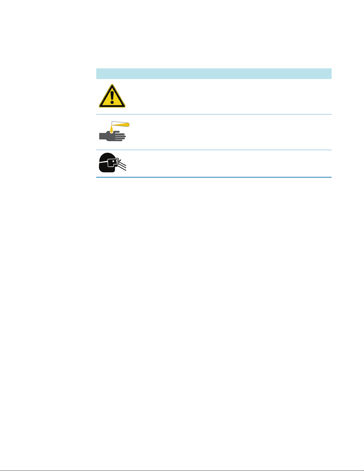
Table 2. Caution symbols and their meanings
Symbol Meaning
General Hazard: A hazard is present that is not included in the
following categories. This symbol also appears on the instrument.
Refer to the instructions in the instrument manual for details on the
hazard.
Chemical: Hazardous chemicals might be present in the instrument.
Wear gloves when handling carcinogenic, corrosive, irritant,
mutagenic, or toxic chemicals. Use only approved containers and
procedures for disposing of waste oil.
Eye Hazard: Eye damage could occur from splattered chemicals or
airborne particles. Wear safety glasses when handling chemicals or
servicing the instrument.
Preface
Contacting Us
There are several ways to contact Thermo Fisher Scientific for the information you need.
To contact Technical Support
Phone 800-532-4752
Fax 561-688-8736
E-mail us.techsupport.analyze@thermofisher.com
Knowledge base www.thermokb.com
Find software updates and utilities to download at mssupport.thermo.com.
To contact Customer Service for ordering information
Phone 800-532-4752
Fax 561-688-8731
E-mail us.customer-support.analyze@thermofisher.com
Web si te www.thermo.com/ms
To get local contact information for sales or service
Go to www.thermoscientific.com/wps/portal/ts/contactus.
To copy manuals from the Internet
Go to mssupport.thermo.com, agree to the Terms and Conditions, and then click
Customer Manuals in the left margin of the window.
Thermo Scientific MS/ETD System Getting Started Guide xv
Page 16

Preface
To suggest changes to documentation or to Help
• Fill out a reader survey online at www.surveymonkey.com/s/PQM6P62.
• Send an e-mail message to the Technical Publications Editor at
techpubs-lcms@thermofisher.com.
xvi MS/ETD System Getting Started Guide Thermo Scientific
Page 17

1
Introduction
The LTQ XL/ETD and LTQ Velos/ETD systems are members of the Thermo Scientific
family of mass spectrometer (MS) detectors, and consist of an ETD module installed at the
back of an LTQ XL or LTQ Velos MS detector. With the LTQ XL/ETD or LTQ Velos/ETD
system you can perform electron transfer dissociation (ETD) mass spectroscopy on analytes.
The LTQ XL and LTQ Velos MS detectors are advanced analytical instruments that include
an atmospheric pressure ionization (API) source, a divert/inject valve, a linear ion trap, a
syringe pump, and the Xcalibur data system.
The MS/ETD System is a source of fluoranthene reagent ions that react with analyte
molecules in the linear ion trap of the LTQ XL or LTQ Velos MS detector. The ETD module
contains two reagent vials, chemical ionization (CI)/carrier gas (nitrogen) handling hardware
and flow restrictors, ion volume and filament, ion optics, and heaters for these components.
The flow restrictors keep the internal pressure of the reagent vials below atmospheric pressure
which prevents the contents of the reagent vials from being expelled into the laboratory
atmosphere.
The nitrogen gas serves two functions in the ETD process. It is both a carrier gas and a CI
vehicle. As a carrier gas, the nitrogen sweeps the reagent from the vial to the ion source where
reagent radical anions are formed.
As a CI vehicle, the nitrogen gas collides with 70eV electrons from the filament in the ion
volume. These 70eV electrons from the filament knock electrons from the nitrogen
molecules, creating nitrogen ions. The secondary electrons resulting from these collisions have
near thermal kinetic energies. The fluoranthene captures these thermal electrons to form
reagent radical anions. The ETD optics transport the reagent radical anions to the linear ion
trap where they react with the analyte.
• Electron Transfer Dissociation
• Types of Experiments
• Tuning and Calibration
• Diagnostics
Thermo Scientific MS/ETD System Getting Started Guide 1
Page 18

1
Introduction
Electron Transfer Dissociation
Electron Transfer Dissociation
ETD provides peptide dissociation by transferring electrons to positively charged peptides,
leading to a rich ladder of sequence ions derived from cleavage at the amide groups along the
peptide backbone. Amino acid side chains and important modifications such as
phosphorylation are left intact.
Types of Experiments
The New Method page of the Instrument Setup window for the LTQ XL (Figure 1) or
LTQ Velos MS detector has buttons for the various types of experiment templates. Open the
template for a particular experiment type, enter the parameters for the experiment, and then
save the entries as part of an Xcalibur instrument method.
The New Method page has two experiment categories:
• LTQ XL and LTQ Vel os E xp eri men t Types
• ETD Experiment Types
2 MS/ETD System Getting Started Guide Thermo Scientific
Page 19

Figure 1. LTQ XL/ETD system New Method page
1
Introduction
Types of Experiments
Thermo Scientific MS/ETD System Getting Started Guide 3
Page 20

1
Introduction
Types of Experiments
LTQ XL and LTQ Velos Experiment Types
As described in the LTQ Series Getting Started Guide, the experiment templates available on all
LTQ XL and LTQ Velos mass spectrometers are as follows:
n
• General MS or MS
• Data-dependent experiments:
– Data Dependent MS/MS
– Data Dependent Triple Play
–Nth Order Double Play
–FAIMS Nth Order Double Play
–Nth Order Triple Play
– Data Dependent NL MS
– Data Dependent product MS
experiment
3
3
– Data Dependent Zoom Map
• Data Dependent Ion Tree
• Ion Mapping
ETD Experiment Types
With the addition of the ETD module to the LTQ XL or LTQ Velos MS detector, two other
experiment templates are available:
• Nth Order Double Play (ETD)—This experiment is useful as a survey experiment when
you cannot determine whether the CID or ETD mode of dissociation works best. For
example, CID works best for dissociating doubly-charged ions while ETD works best for
ions of a higher charge state.
• Data Dependent NL MS
dissociation might make it easier to identify sites of the neutral loss (modification). ETD
dissociation is also useful when there are multiple sites of modification.
For additional information, see Chapter 6, “Running an Xcalibur Experiment by Using
ETD.”
3
(ETD)—Repeating the MS/MS experiment by using ETD
4 MS/ETD System Getting Started Guide Thermo Scientific
Page 21

Tuning and Calibration
Tune parameters are instrument parameters (for example, ETD optics) whose values can vary
with the type of experiment or analyte being mass analyzed. Tuning the instrument on an
analyte ensures sensitivity and mass resolution.
Calibration parameters are instrument parameters whose values do not vary with the type of
experiment. You calibrate the mass spectrometer to ensure mass accuracy.
IMPORTANT Thermo Fisher Scientific recommends that you calibrate the mass
spectrometer at least once every three months and that you check the calibration about
once a week.
To tune and calibrate the LTQ XL/ETD or LTQ Velos/ETD system, perform these basic
steps:
• Tune and calibrate the LTQ XL or LTQ Velos MS detector as described in the LTQ S eri es
Getting Started Guide.
1
Introduction
Tuning and Calibration
Diagnostics
• Tune the optics in the ETD module as described in Chapter 3, “Tuning.”
To learn more about some of the diagnostic tools and tests, refer to the LTQ Series Getting
Started Guide and the LTQ Series Hardware Manual. (At this time, not all diagnostic tools or
tests are discussed in the product guides.)
Thermo Scientific MS/ETD System Getting Started Guide 5
Page 22

Page 23

2
Setting Up the Xcalibur Instrument Configuration
Follow these procedures to add the LTQ XL or LTQ Velos MS detector and the reagent ion
source (ETD module) to the Xcalibur instrument configuration and to specify some of their
configuration options.
• Adding the MS Detector to the Xcalibur Instrument Configuration
• Specifying the Reagent Ion Source for the MS Detector
Adding the MS Detector to the Xcalibur Instrument Configuration
To control the ETD source and the LTQ XL or LTQ Velos MS detector from the Xcalibur
data system, add these devices to the Xcalibur instrument configuration.
To add the MS detector to the list of configured devices
1. Close the Xcalibur data system and Tune Plus application.
2. On the Windows taskbar, choose Start > Programs > Thermo Foundation 1.0 >
Instrument Configuration (Figure 2).
Note For Xcalibur data system version 2.0.7 or earlier, choose Start > Programs >
Xcalibur > Instrument Configuration.
Thermo Scientific MS/ETD System Getting Started Guide 7
Page 24

2
Setting Up the Xcalibur Instrument Configuration
Adding the MS Detector to the Xcalibur Instrument Configuration
Figure 2. Thermo Foundation Instrument Configuration window
3. Select the devices to control from the Xcalibur data system as follows:
a. In the Device Types list, select All.
b. In the Available Devices list, double-click the LTQ X L M S or LTQ Ve lo s M S icon to
add it to the Configured Devices list (Figure 3).
8 MS/ETD System Getting Started Guide Thermo Scientific
Page 25

2
Setting Up the Xcalibur Instrument Configuration
Adding the MS Detector to the Xcalibur Instrument Configuration
Figure 3. Thermo Foundation Instrument Configuration window with configured devices
Thermo Scientific MS/ETD System Getting Started Guide 9
Page 26

2
Setting Up the Xcalibur Instrument Configuration
Specifying the Reagent Ion Source for the MS Detector
Specifying the Reagent Ion Source for the MS Detector
Specify the ETD module as the reagent ion source for the LTQ XL or LTQ Velos MS
detector.
To specify the reagent ion source
1. In the Thermo Foundation Instrument Configuration window, in the Configured
Devices list, double-click the LTQ X L MS or LTQ Ve lo s M S icon to open the
Configuration dialog box (Figure 4).
Figure 4. LTQ XL Configuration dialog box
2. In the left pane, select Reagent Ion Source.
The reagent ion source configuration appears (for the LTQ Velos MS detector, see
Figure 5).
3. Select the Reagent Ion Source Configured check box.
You must manually select this check box for MS/ETD systems.
10 MS/ETD System Getting Started Guide Thermo Scientific
Page 27

2
Setting Up the Xcalibur Instrument Configuration
Specifying the Reagent Ion Source for the MS Detector
Figure 5. LTQ Velos Configuration dialog box with the reagent ion source configuration
The Reagent Ion Source Configured and the Use Cooling Gas check boxes are selected by
default. Also shown is information about the contents of the reagent vials.
Tip The Use Cooling Gas option makes nitrogen gas available when you must cool
down the reagent vials. To save your supply of cooling gas, clear the check box to turn
it off.
4. (Optional) Select the Use Low Vial Temperature check box to heat the vial to 90 °C,
rather than 108 °C (Figure 6).
Note The lower vial temperature can extend the lifetime of the filament, but it might
increase the injection time.
Figure 6. LTQ Velos Configuration dialog box with the low vial temperature option selected
Thermo Scientific MS/ETD System Getting Started Guide 11
Page 28

2
Setting Up the Xcalibur Instrument Configuration
Specifying the Reagent Ion Source for the MS Detector
5. Click OK.
A message box opens:
In order for the configuration changes to take effect, you will need to reboot the data
system and then the LTQ.
6. Click OK.
7. Reboot the data system.
8. Reboot the LTQ XL or LTQ Velos MS detector.
For instructions, refer to the LTQ Ser ies Ha rd ware Ma nua l.
12 MS/ETD System Getting Started Guide Thermo Scientific
Page 29

3
Tuning
Tuning the optics in the reagent ion source provides settings for optimum transmission of
reagent ions (fluoranthene).
• Tuning the Reagent Ion Optics
• Viewing the Reagent Ion Optics Settings
• Saving the ETD Tune Method
Opening the Tune Plus Window
There are several methods for opening the Tune Plus window.
To open the Tune Plus window
Do one of the following to open the Tune Plus window (Figure 7):
• On the Windows taskbar, choose Start > Programs > Thermo Instruments > LTQ >
model Tu n e , where model is your specific MS/ETD system.
Note For LTQ Series version 2.5.0 or earlier, choose Start > Programs >
Xcalibur > model Tu n e .
• In the Xcalibur application, choose Roadmap view > Instrument Setup > model
(left pane) > Tune Plus.
• In the Xcalibur application, choose Roadmap view > Instrument Setup, model
(menu toolbar) > Start Tune Plus.
Thermo Scientific MS/ETD System Getting Started Guide 13
Page 30

3
Tuning
Tuning the Reagent Ion Optics
Figure 7. Tune Plus window
Tuning the Reagent Ion Optics
This section describes the three ways to tune the ion optics within the reagent ion source:
• “Automatic Tuning of the Reagent Ion Optics” on page 15
Automatic tuning of the reagent ion optics is the best method for most situations. Use
manual tuning to manually optimize reagent ion optics parameters and reagent ion source
parameters not automatically tuned, such as CI gas pressure, electron energy, and
emission current.
• “Manually Tuning the Reagent Ion Source” on page 19
Manual tuning lets you observe the effects of adjusting these parameters as you change
them.
• “Semi-Automatically Tuning the Reagent Ion Optics” on page 22
Semi-automatic tuning lets you optimize each lens setting individually within an
optimization range and according to the selected step size.
14 MS/ETD System Getting Started Guide Thermo Scientific
Page 31

Automatic Tuning of the Reagent Ion Optics
On Off Standby
To automatically tune the reagent ion optics
1. Open the Tune Plus window; see the instructions on page 13.
2. Click the On/Off/Standby button to select the On mode.
When clicked, this button cycles through the power modes shown in the left margin.
Note
When on, the System LED on the front panel of the MS detector turns green and the
high voltage to the electron multipliers turns on.
The following conditions can cause the MS/ETD System to remain in standby mode
even though you try to turn it on:
• Attempting to turn on the reagent ion source when the restrictor heater, source
heater, and the transfer line heater are not at their target temperatures.
3
Tuning
Tuning the Reagent Ion Optics
• When either the LTQ XL/ETD or LTQ Velos/ETD MS detector or the
MS/ETD System goes into standby mode. Reagent vial nitrogen cooling turns on
if the vials are at an elevated temperature.
• Exception: If you put the LTQ XL/ETD or LTQ Velos/ETD system in standby
mode, the cooling nitrogen turns on after a one hour delay.
• Whenever the pressure in the LTQ XL or LTQ Velos MS detector or the
MS/ETD System exceeds its protection limit. Reagent vial nitrogen cooling turns
on if the vials are at an elevated temperature.
• Whenever the flow of reagent ions becomes insufficient as determined by the
automatic gain control (AGC) setting. When this occurs the LTQ XL/ETD or
LTQ Velos/ETD system completes the Xcalibur sequence step into progress
before going in standby mode. This prevents the loss of analysis results that might
be affected by the reduced reagent ion flow.
3. Click the Display Graph View ( ) button.
Thermo Scientific MS/ETD System Getting Started Guide 15
Page 32

3
Tuning
Tuning the Reagent Ion Optics
4. Turn on the Reagent Ion Source as follows:
a. Choose Setup > Reagent Ion Source to open this dialog box (Figure 8).
Figure 8. Reagent Ion Source dialog box
b. Select the Reagent Ion Source On check box.
c. Select the Filament On check box.
For tuning, you must manually select the Filament On check box.
Note
If the reagent vials are not at their target temperature, a message appears:
Reagent Vial NOT At Temperature! Please wait …
The System LED on the ETD module flashes green to indicate that the reagent
vial heaters are turned on but not at their target temperatures (the other heaters
are at their target temperatures).
When the reagent vial heaters reach their target temperatures, the System LED
illuminates solid green.
When the reagent vials reach their target temperature, voltage is applied to the
ETD module ion optics, and when the check box is selected, the filament turns
on and the Filament LED illuminates solid green.
16 MS/ETD System Getting Started Guide Thermo Scientific
Page 33

3
Tuning
Tuning the Reagent Ion Optics
5. In the Reagent Ion Source dialog box, select the View Reagent Ion Spectra check box.
Figure 9 shows the reagent spectrum at peak m/z 202.
Figure 9. Spectrum displayed in Tune Plus
Thermo Scientific MS/ETD System Getting Started Guide 17
Page 34

3
Nee
Tuning
Tuning the Reagent Ion Optics
6. In the Tune Plus window, click the Tu n e ( ) button to open this dialog box
(Figure 10).
Figure 10. Automatic page in the Tune dialog box
7. Click Start.
The system begins automatically tuning the ion optics of the reagent ion source. The
Status area displays the message “Optimization Complete” after completing automatic
tuning. This message also states the percentage change in the reagent ion signal
(m/z = 202) intensity relative to the prior value. A typical reagent signal intensity is about
5E6 to 1E7 in profile mode when the system has been cleaned and the ion volume is new.
8. Repeat Automatic Tune if the percentage change is greater than 20%.
Note This is an iterative process. At some point there will be no more improvements in
signal intensity.
18 MS/ETD System Getting Started Guide Thermo Scientific
Page 35

Manually Tuning the Reagent Ion Source
To manually tune the reagent ion source
1. Open the Tune Plus window; see the instructions on page 13.
2. Click the Display Graph View ( ) button.
3. Turn on the Reagent Ion Source as follows:
a. Choose Setup > Reagent Ion Source (Figure 8 on page 16).
b. Select the Reagent Ion Source On check box.
c. Select the Filament On check box.
Note
If the reagent vials are not at their target temperature, a message appears:
Reagent Vial NOT At Temperature! Please wait …
3
Tuning
Tuning the Reagent Ion Optics
The System LED on the ETD module flashes green to indicate that the reagent
vial heaters are turned on but not at their target temperatures (the other heaters
are at their target temperatures).
When the reagent vial heaters reach their target temperatures, the System LED
illuminates solid green.
When the reagent vials reach their target temperature, voltage is applied to the
ETD module ion optics, and when the check box is selected, the filament turns
on and the Filament LED illuminates solid green.
4. In the Reagent Ion Source dialog box, select the View Reagent Ion Spectra check box.
5. In the Tune Plus window, click the Tu n e ( ) button to open this dialog box
(Figure 10).
Thermo Scientific MS/ETD System Getting Started Guide 19
Page 36

3
Tuning
Tuning the Reagent Ion Optics
6. In the Tune Plus window, choose Setup > Reagent Ion Optics to open this dialog box
(Figure 11).
Figure 11. Reagent Ion Optics dialog box
7. In the Tune dialog box (Figure 10 on page 18), click the Manual tab (Figure 12).
Figure 12. Manual page in the Tune dialog box
20 MS/ETD System Getting Started Guide Thermo Scientific
Page 37

8. Select the Reagent Ion from Vial 1 or Reagent Ion from Vial 2 check box, whichever
appears and is available.
9. Click Start.
A plot of the reagent ion intensity appears (Figure 13). You can observe:
• The response of the reagent ion intensity to changes in the lens parameters in the
Reagent Ion Optics dialog box (Figure 11 on page 20)
• The emission current, CI gas pressure, and electron energy in the Reagent Ion Source
dialog box (Figure 8 on page 16)
Adjust these parameters to achieve the maximum reagent ion signal intensity.
Figure 13. Graph view of the reagent ion source tuning in the Tune Plus window for the LTQ XL
3
Tuning
Tuning the Reagent Ion Optics
Thermo Scientific MS/ETD System Getting Started Guide 21
Page 38

3
Tuning
Tuning the Reagent Ion Optics
Semi-Automatically Tuning the Reagent Ion Optics
Use the semi-automatic tuning method to fine-tune the lens parameters to a range of settings
and in step increments.
To semi-automatically tune the reagent ion optics
1. Open the Tune Plus window; see the instructions on page 13.
2. Click the Display Graph View ( ) button.
3. Turn on the Reagent Ion Source as follows:
a. Choose Setup > Reagent Ion Source (Figure 8 on page 16).
b. Select the Reagent Ion Source On check box.
c. Select the Filament On check box.
Note
If the reagent vials are not at their target temperature, a message appears:
Reagent Vial NOT At Temperature! Please wait …
The System LED on the ETD module flashes green to indicate that the reagent
vial heaters are turned on but not at their target temperatures (the other heaters
are at their target temperatures).
When the reagent vial heaters reach their target temperatures, the System LED
illuminates solid green.
When the reagent vials reach their target temperature, voltage is applied to the
ETD module ion optics, and when the check box is selected, the filament turns
on and the Filament LED illuminates solid green.
4. In the Reagent Ion Source dialog box, select the View Reagent Ion Spectra check box.
5. In the Tune Plus window, click the Tu n e ( ) button to open this dialog box (Figure 10
on page 18).
22 MS/ETD System Getting Started Guide Thermo Scientific
Page 39

6. Click the Semi-Automatic tab (Figure 14).
Figure 14. Semi-Automatic page in the Tune dialog box
3
Tuning
Tuning the Reagent Ion Optics
7. Under What to Optimize, select one of the following items to tune:
• Reagent ion lens 1 (V)
• Reagent ion gate lens (V)
• Reagent ion lens 2 (V)
• Reagent ion lens 3 (V)
• Back Multipole Offset (V)
• Back lens (V)
8. Under Optimization Range, adjust the settings in the Start, End, and Step boxes.
9. Click Start.
Thermo Scientific MS/ETD System Getting Started Guide 23
Page 40

3
Tuning
Viewing the Reagent Ion Optics Settings
Viewing the Reagent Ion Optics Settings
To view the current reagent ion optics settings
1. Open the Tune Plus window; see the instructions on page 13.
2. Choose Setup > Reagent Ion Optics to open this dialog box (Figure 15).
The Reagent Ion Optics dialog box shows the optimized settings from the tuning process.
Figure 15. Reagent Ion Optics dialog box
3. Click OK.
Saving the ETD Tune Method
After completing the tuning, you can save the ETD Tune parameters in a tune method.
To save the tune method
1. In the Tune Plus window, click the Save
2. Browse to a location, and then specify a file name.
3. Click Save.
( ) button.
24 MS/ETD System Getting Started Guide Thermo Scientific
Page 41

4
Daily Operation
On Off Standby
To prepare the LTQ XL/ETD or LTQ Velos/ETD system for daily operation, follow these
procedures.
• Before Operating the LTQ XL/ETD or LTQ Velos/ETD System
• Turning On the Reagent Ion Source
• After Operating the System
Before Operating the LTQ XL/ETD or LTQ Velos/ETD System
Follow these procedures every day before beginning the first analysis:
• Checking the System Mode
• Checking the Vacuum Pressure
• Checking the Gas Supplies
Checking the System Mode
Before beginning your daily work, turn on the mass spectrometer.
To turn on the mass spectrometer
1. Open the Tune Plus window; see the instructions on page 13.
2. Click the On/Off/Standby button to select the On mode.
When clicked, this button cycles through the power modes shown in the left margin.
Thermo Scientific MS/ETD System Getting Started Guide 25
Page 42

4
Daily Operation
Before Operating the LTQ XL/ETD or LTQ Velos/ETD System
Note
When on, the System LED on the front panel of the MS detector turns green and the
high voltage to the electron multipliers turns on.
The following conditions can cause the MS/ETD System to remain in standby mode
even though you try to turn it on:
• Attempting to turn on the reagent ion source when the restrictor heater, source
heater, and transfer line heater are not at their target temperatures.
• When either the LTQ XL/ETD or LTQ Velos/ETD MS detector or the
MS/ETD System goes into standby mode. Reagent vial nitrogen cooling turns on
if the vials are at an elevated temperature.
• Exception: If you put the LTQ XL/ETD or LTQ Velos/ETD system in standby
mode, the cooling nitrogen turns on after a one hour delay.
• Whenever the pressure in the LTQ XL or LTQ Velos MS detector or the
MS/ETD System exceeds its protection limit. Reagent vial nitrogen cooling turns
on if the vials are at an elevated temperature.
• Whenever the flow of reagent ions becomes insufficient as determined by the
AGC setting. When this occurs the LTQ XL/ETD or LTQ Velos/ETD system
completes the Xcalibur sequence step in progress before going into standby mode.
This prevents the loss of analysis results that might be affected by the reduced
reagent ion flow.
Checking the Vacuum Pressure
Check the vacuum pressure before operating the system.
To check the vacuum pressure
1. In the Tune Plus window, choose Setup > Vacuum (Figure 16).
Figure 16. Ion Trap page
26 MS/ETD System Getting Started Guide Thermo Scientific
Page 43

4
Daily Operation
Before Operating the LTQ XL/ETD or LTQ Velos/ETD System
2. Click the Reagent tab (Figure 17).
Figure 17. Reagent page
3. Compare the current values of the pressures in the vacuum manifold with the following
values.
Condition
CI gas pressure set to 20 psi 20–35 × 10–5 Torr 0.1–0.01 Torr
Note
• If the current values are higher than normal, there might be an air leak.
• If the pressure is above 40 × 10
within the last 30 to 60 minutes, wait another 30 minutes and recheck the pressure. If
the pressure decreases with time, check the pressure periodically until it is within the
typical range for the MS detector.
• If the pressure remains high, the system might have an air leak.
Checking the Gas Supplies
Check the two nitrogen gas supplies for the ETD module before operating the system.
To check the gas supplies
1. Check the connections to the back of the ETD module for the two nitrogen lines.
Ion gauge reading
(analyzer region)
–5
Torr in the analyzer region and the system restarted
Convectron™ gauge reading
(foreline, capillary skimmer region)
2. Verify that the pressure of the high-purity nitrogen at the MS detector is 690 ±140 kPa
(100 ±20 psi).
If necessary, adjust the pressure with the tank pressure regulator.
3. Verify that the pressure of the reagent carrier gas (ultra high-purity helium/nitrogen or
nitrogen) at the ETD module is 275±35kPa (39.9±5psi).
If necessary, adjust the pressure with the tank pressure regulator.
Thermo Scientific MS/ETD System Getting Started Guide 27
Page 44

4
Daily Operation
Turning On the Reagent Ion Source
4. Ensure that there is sufficient gas for the analysis.
Typical nitrogen gas consumption per day (when nitrogen is on 24 hours per day) is
3
between 5560 L (196.3 ft
) and 26700 L (943 ft3). If necessary, replace the tank. The
ETD module consumes less than 1 ATM cc/m of reagent carrier gas, so a standard large
bottle (245 ft
3
) of gas should last approximately two years.
For more information about gas requirements, refer to the LTQ Series Preinstallation
Requirements Guide.
Turning On the Reagent Ion Source
Even when the ETD module is on, the reagent ion source within it stays off until you turn
it on.
To turn on the reagent ion source
1. Open the Tune Plus window; see the instructions on page 13.
2. Choose Setup > Reagent Ion Source to open this dialog box (Figure 18).
Figure 18. Reagent Ion Source dialog box
3. Select the Reagent Ion Source On check box.
4. Select the Filament On check box.
For tuning, you must manually select the Filament On check box.
28 MS/ETD System Getting Started Guide Thermo Scientific
Page 45

4
Daily Operation
Turning On the Reagent Ion Source
Note
If the reagent vials are not at their target temperature, a message appears:
Reagent Vial NOT At Temperature! Please wait …
The System LED on the ETD module flashes green to indicate that the reagent vial
heaters are turned on but not at their target temperatures (the other heaters are at
their target temperatures).
When the reagent vial heaters reach their target temperatures, the System LED
illuminates solid green.
When the reagent vials reach their target temperature, voltage is applied to the ETD
module ion optics, and when the check box is selected, the filament turns on and the
Filament LED illuminates solid green.
5. Select the View Reagent Ion Spectra check box.
6. Click OK.
Reagent ion peaks appear in the Tune Plus spectrum view (Figure 19).
Thermo Scientific MS/ETD System Getting Started Guide 29
Page 46

4
Daily Operation
Turning On the Reagent Ion Source
Figure 19. Fluoranthene radical anion mass spectrum
7. Check the spectrum and do one of the following:
• If the spectrum is satisfactory, proceed to step 8.
• If the spectrum is not satisfactory, tune the reagent ion optics as described in
Chapter 3, “Tuning.”
8. In the Reagent Ion Source dialog box, clear the View Reagent Ion Spectra check box.
This action clears the Tune Plus spectrum view from the ETD module.
30 MS/ETD System Getting Started Guide Thermo Scientific
Page 47

After Operating the System
On Off Standby
After operating the LTQ XL/ETD or LTQ Velos/ETD system, follow these procedures:
• Placing the System in Standby Mode
• Purging the Oil in the Fore Pump
Placing the System in Standby Mode
To place the system in standby mode
1. Open the Tune Plus window; see the instructions on page 13.
2. Choose Setup > Reagent Ion Source to open this dialog box (Figure 20).
Figure 20. Reagent Ion Source dialog box
4
Daily Operation
After Operating the System
Thermo Scientific MS/ETD System Getting Started Guide 31
3. Clear the Reagent Ion Source On check box.
When you clear this check box, the ETD source and reagent heaters go in standby mode
and the filament and vial heaters turn off. Simultaneously, a valve opens to allow nitrogen
gas to cool the reagent vials. This cooling nitrogen runs until the vials cool down to 70 °C
(158 °F). When you hear the sound of escaping gas, the cooling nitrogen has turned
on—this sound is a normal part of the instrument operation.
4. In the Tune Plus window, click the On/Off/Standby button to select the Standby mode.
Page 48

4
Daily Operation
After Operating the System
Purging the Oil in the Fore Pump
Purge (decontaminate) the oil in the fore pump daily to remove water and other dissolved
chemicals from the pump oil. For details, refer to the manufacturer’s documentation.
32 MS/ETD System Getting Started Guide Thermo Scientific
Page 49

5
Performing an ETD Infusion Experiment
This chapter discusses the ETD infusion experiment.
• Viewing the Injection Reagent Settings
• Troubleshooting an AGC Target Error
• Obtaining an ETD Spectrum for Angiotensin I
• Optimizing the Reagent Ion Reaction Time
Viewing the Injection Reagent Settings
The parameters on the Reagent page in the Injection Control dialog box (Figure 22) regulate
the number of reagent ions admitted into the ion trap of the LTQ XL or LTQ Velos MS
detector
To view the injection reagent ion settings
1. Open the Tune Plus window; see the instructions on page 13.
2. Choose Setup > Injection Control to open this dialog box (Figure 21).
Figure 21. Ion Trap page in the Injection Control dialog box
Thermo Scientific MS/ETD System Getting Started Guide 33
Page 50

5
Performing an ETD Infusion Experiment
Viewing the Injection Reagent Settings
3. Click the Reagent tab (Figure 22).
Figure 22. Reagent page in the Injection Control dialog box
The ETD reagent injection control consists of two parameters:
• Max. Inject Time (ms)—Specifies the maximum time that the system allows for
anions to be injected into the trap. The default value is 50 ms.
• AGC Target—Sets the target number of reagent anions to be injected into the trap to
perform ETD. The default value is 1E5.
4. Click OK or Cancel.
The reagent ion source injects reagent anions into the trap until the ETD AGC target is
reached. The time allowed to reach the ETD AGC target cannot exceed the Max. Inject Time
setting—the maximum injection time takes precedence over the AGC target.
34 MS/ETD System Getting Started Guide Thermo Scientific
Page 51

Troubleshooting an AGC Target Error
On Off Standby
If the AGC target is not reached because of the maximum injection time limit, the system
displays an error message:
Maximum Injection time limit exceeded.
This implies that the sensitivity of the reagent ion source is too low. There are several ways to
deal with this error:
• Increase the sensitivity of the source by running the automatic tuning of the reagent ion
source; see “Tuning the Reagent Ion Optics” on page 14.
• Clean or change the ion volume; refer to Chapter 6, “Maintenance,” in the ETD Module
Hardware Manual. The sensitivity decrease might be due to a dirty ion volume. A
sufficiently contaminated ion volume causes the maximum injection time limit to be
exceeded.
• Clean the reagent ion source and its optics; refer to Chapter 6, “Maintenance,” in the
ETD Module Hardware Manual. The sensitivity decrease might be due to a dirty reagent
ion source, its optics, or both. A contaminated reagent ion source or its optics can also
cause the maximum injection time limit to be exceeded.
5
Performing an ETD Infusion Experiment
Troubleshooting an AGC Target Error
• Increase the emission current in the Reagent Ion Source dialog box (Figure 8 on page 16).
However, an increase in emission current might decrease the filament life.
• Increase the maximum injection time limit. This is a temporary way to eliminate the error
message. You can increase the maximum injection time limit up to the limits imposed by
the overall scan cycle time.
The maximum injection time limit and AGC target influence the ETD reaction results.
Obtaining an ETD Spectrum for Angiotensin I
This section assumes that you are infusing Angiotensin I into the LTQ XL/ETD or
LTQ Velos/ETD system according to the procedures in the LTQ Series Getting Started Guide.
For instructions about preparing the Angiotensin I solutions, see Appendix B, “Angiotensin I
Solutions.”
To obtain an ETD spectrum of Angiotensin I
1. Open the Tune Plus window; see the instructions on page 13.
2. Click the On/Off/Standby button to select the On mode.
3. Turn on the reagent ion source; see “Turning On the Reagent Ion Source” on page 28.
Thermo Scientific MS/ETD System Getting Started Guide 35
Page 52

5
Activation Type = ETD
Performing an ETD Infusion Experiment
Obtaining an ETD Spectrum for Angiotensin I
4. In the Tune Plus window, click the Define Scan ( ) button to open this
dialog box (Figure 23).
Figure 23. Define Scan dialog box
5. Under MSn Settings, in the n = 2 row, enter the Parent Mass (m/z) of the 3+ charge state
of Angiotensin I.
The molecular weight of Angiotensin I (acetate hydrate) is 1296 Da. The mass-to-charge
3+
ratio of the parent ion [M + 3H]
is 433.0.
6. In the Act. Type list, select ETD (Figure 24).
Figure 24. Activation Type list in the Define Scan dialog box
36 MS/ETD System Getting Started Guide Thermo Scientific
Page 53

7. Click OK.
The Define Scan dialog box closes and Tune Plus displays the ETD MS/MS spectrum of
Angiotensin I (Figure 25).
Figure 25. ETD MS/MS spectrum of Angiotensin I
5
Performing an ETD Infusion Experiment
Obtaining an ETD Spectrum for Angiotensin I
Thermo Scientific MS/ETD System Getting Started Guide 37
Page 54

5
Performing an ETD Infusion Experiment
Optimizing the Reagent Ion Reaction Time
Optimizing the Reagent Ion Reaction Time
The default reagent ion reaction time of 100 ms is appropriate for most analyses. In some
cases obtaining an optimized reagent ion reaction time is helpful for a specific analyte. The
procedures in this section assume that the system generates the reagent ions as described in
“Turning On the Reagent Ion Source” on page 28.
To optimize the reagent ion reaction time
1. Turn on ETD activation for the analyte (Angiotensin I, in this case).
2. Open the Tune Plus window; see the instructions on page 13.
3. Click the Define Scan ( ) button to open this dialog box (Figure 23 on
page 36).
4. Under MSn Settings, in the Parent Mass (m/z) box, enter the mass for the analyte.
5. Under MSn Settings, in the Act. Type list, select ETD.
6. In the Tune Plus window, click the Tu n e ( ) button to open this dialog box.
The Tune dialog box has two additional tabs for tuning ETD (Figure 26).
Figure 26. Tune dialog box for ETD
38 MS/ETD System Getting Started Guide Thermo Scientific
Page 55

5
Performing an ETD Infusion Experiment
7. Click the Reagent Ion Reaction Time tab (Figure 27).
Figure 27. Reagent Ion Reaction Time page in the Tune dialog box
Optimizing the Reagent Ion Reaction Time
8. Click Start.
Tune Plus generates a graph showing the intensity of the m/z of interest versus reaction
time. The Status area of the window shows a reagent ion reaction time after completing
the tune process.
A message prompts you to accept the optimized value. If you accept the optimized value,
the reagent ion reaction time parameter sets to this optimized value in the Define Scan
dialog box. Otherwise, it returns to its previous value.
The reagent ion reaction time is now optimized based on total ion current (TIC).
To optimize on a particular product ion, in the Tune dialog box under What to Optimize
On (Figure 27), select the Product Ion Mass (m/z) option, enter the m/z of the selected
product ion, and then repeat step 7.
Thermo Scientific MS/ETD System Getting Started Guide 39
Page 56

Page 57

6
Running an Xcalibur Experiment by Using ETD
This chapter describes the two ETD-specific experiment templates provided by the Xcalibur
data system. For more information, refer to the LTQ Series Getting Started Guide.
• Nth Order Double Play (ETD) Experiment
3
• Data Dependent NL MS
Experiment
Thermo Scientific MS/ETD System Getting Started Guide 41
Page 58

6
Running an Xcalibur Experiment by Using ETD
Nth Order Double Play (ETD) Experiment
Nth Order Double Play (ETD) Experiment
To create an Nth Order Double Play (ETD) method
1. Choose Start > Programs > Thermo Xcalibur > Xcalibur (Figure 28).
Note For Xcalibur data system version 2.0.7 or earlier, choose Start > Programs >
Xcalibur > Xcalibur.
Figure 28. Xcalibur Roadmap view of the Home Page
42 MS/ETD System Getting Started Guide Thermo Scientific
Page 59

6
2. Click the Instrument Setup icon (Figure 29).
Figure 29. Instrument Setup window for Thermo EASY-nLC
Running an Xcalibur Experiment by Using ETD
Nth Order Double Play (ETD) Experiment
Thermo Scientific MS/ETD System Getting Started Guide 43
Page 60

6
Running an Xcalibur Experiment by Using ETD
Nth Order Double Play (ETD) Experiment
3. In the left Available Devices pane, click the LTQ X L MS icon (shown in Figure 30) or
LTQ Vel os M S icon to open the New Method page for the device.
Figure 30. New Method page for the LTQ XL/ETD system
4. Under Select ETD Experiment Type, click Nth Order Double Play (ETD) to open this
dialog box (Figure 31).
The Initialize Method with Additional ETD Scan Event check box is selected as the
default setting.
Figure 31. Nth Order Double Play dialog box
5. In the Analyze Top N Peaks box, enter the number of top peaks.
44 MS/ETD System Getting Started Guide Thermo Scientific
Page 61

6
Running an Xcalibur Experiment by Using ETD
Nth Order Double Play (ETD) Experiment
6. Click OK.
The Instrument Setup window opens showing the Nth Order Double Play with ETD
template (Figure 32).
Figure 32. Nth Order Double Play with ETD template
7. Enter the scan event settings by clicking the Scan Event 1, Scan Event 2, and
Scan Event 3 bars.
For Scan Event 2 and Scan Event 3, the Dependent Scan check box (lower left corner)
and its adjacent Settings button become active.
Thermo Scientific MS/ETD System Getting Started Guide 45
Page 62

6
Running an Xcalibur Experiment by Using ETD
Nth Order Double Play (ETD) Experiment
8. (For Scan Event 2 and Scan Event 3 only) Click Settings to open the Data Dependent
Settings dialog box (Figure 33).
Figure 33. Data Dependent Settings dialog box
9. In the left pane, under the Scan Event list, click Activation to see the activation
parameters (Figure 34).
The activation type is automatically set to ETD.
Figure 34. Activation parameters
10. In the Default Charge State box, enter a value of 5 or more.
11. In the Isolation Width (m/z) box, enter a value between 2 and 3.
The Normalized Collision Energy and Activation Q parameters are unavailable because
they are not applicable to ETD.
12. In the Activation Time (ms) box, leave the default value or enter a different value as
described in “Optimizing the Reagent Ion Reaction Time” on page 38.
46 MS/ETD System Getting Started Guide Thermo Scientific
Page 63

13. In the Tune Plus window, click the Save ( ) button.
14. Browse to the drive:\Xcalibur\methods folder, and specify a file name.
15. Click Save.
Data Dependent NL MS3 Experiment
6
Running an Xcalibur Experiment by Using ETD
Data Dependent NL MS3 Experiment
To run a Data Dependent NL MS
3
(ETD) experiment
1. Choose Start > Programs > Xcalibur > Xcalibur (Figure 28 on page 42).
2. Click the Instrument Setup icon (Figure 29 on page 43).
3. In the Available Devices pane, click the LTQ X L MS or LTQ Ve los MS icon to open the
New Method page (Figure 30 on page 44).
4. Under Select ETD Experiment Type, click Data Dependent NL MS3 (ETD) to open
this dialog box (Figure 35).
The Initialize Method to Repeat the MS2 Event Using ETD check box is selected as the
default setting.
Figure 35. Data Dependent NL MS3 dialog box
5. In the Analyze Top N Peaks box, enter the number of top peaks.
Thermo Scientific MS/ETD System Getting Started Guide 47
Page 64

6
Running an Xcalibur Experiment by Using ETD
Data Dependent NL MS3 Experiment
6. In the Neutral Loss Masses table, do one of the following:
• Type the mass and name for the neutral loss masses to identify.
• Click Import to import a list of neutral loss masses from a tab-delimited text file or
from an XML file.
Figure 36 shows an example of a populated neutral loss table for a single phosphorylation
modification where the ion of interest might have a charge state of 1+, 2+, or 3+.
Figure 36. Neutral loss masses table example
48 MS/ETD System Getting Started Guide Thermo Scientific
Page 65

6
Running an Xcalibur Experiment by Using ETD
Data Dependent NL MS3 Experiment
7. Click OK to open the Data Dependent NL MS3 template (Figure 37).
Figure 37. Data Dependent NL MS3 template
8. Enter the scan event settings by clicking the Scan Event 1, Scan Event 2, and
Scan Event 3 bars.
For Scan Event 2 and Scan Event 3, the Dependent Scan check box (lower left corner)
and its adjacent Settings button become active.
9. (For Scan Event 2 and Scan Event 3 only) Click Settings to open the Data Dependent
Settings dialog box (Figure 33 on page 46).
10. In the left pane, under the Scan Event list, click Activation to see the activation
parameters (Figure 34 on page 46).
The activation type is automatically set to ETD.
11. In the Default Charge State box, enter a value of 5 or more.
Thermo Scientific MS/ETD System Getting Started Guide 49
Page 66

6
Running an Xcalibur Experiment by Using ETD
Data Dependent NL MS3 Experiment
12. In the Isolation Width (m/z) box, enter a value between 2 and 3.
The Normalized Collision Energy and Activation Q parameters are unavailable because
they are not applicable to ETD.
13. In the Activation Time (ms) box, leave the default value or enter a different value as
described in “Optimizing the Reagent Ion Reaction Time” on page 38.
14. In the Tune Plus window, click the Save
( ) button.
15. Browse to the drive:\Xcalibur\methods folder, and specify a file name.
16. Click Save.
50 MS/ETD System Getting Started Guide Thermo Scientific
Page 67

7
Troubleshooting
The MS/ETD System uses the following consumables:
•Filament
• Fluoranthene
•Ion volume
After a period of time, you might need to replenish the ETD fluoranthene reagent, replace the
filament, and clean or replace the ion volume. As the consumables are depleted, the ETD
reagent m/z peak intensity diminishes (m/z = 202 in negative polarity mode). Periodically
checking this peak intensity is a good way to monitor the ETD module consumables. To view
the ETD reagent m/z signal, follow the procedure in “Turning On the Reagent Ion Source” on
page 28.
Tip Expect the filament and ion volume to last for about 400 to 500 hours of operation,
and a vial of fluoranthene reagent to last for several months or more.
Ta bl e 3 lists some ETD module problems, their causes, and their possible solutions.
Thermo Scientific MS/ETD System Getting Started Guide 51
Page 68

7
Troubleshooting
Table 3. ETD module problems, causes, and solutions
Problem Cause Solution
With the emission current at the
correct level, no ions appear at
m/z 202.
With the emission current at the
correct level, the m/z 202 signal
intensity drops slowly over several
days.
With the emission current at the
correct level, the m/z 202 signal
significantly drops within one hour.
The m/z 202 is outside of the mass
Set the starting mass lower.
range.
The system is not displaying the
reagent ion spectra. After
automatically tuning the reagent ion
In the Reagent Ion Source dialog box
(Figure 18 on page 28), select the View
Reagent Ion Spectra check box.
source, the spectrum view redisplays
the spectra of ions from the API
source, and the View Reagent Ion
Source check box in the Reagent Ion
Source dialog box is clear.
The filament is bent.
Replace the filament as described in the
ETD Module Hardware Manual.
The ion volume is worn or
contaminated.
Clean or replace the ion volume when
the ion injection time exceeds 100 ms as
described in the ETD Module Hardware
Manual.
The reagent vial might be empty. Replace the fluoranthene vial as
described in the ETD Module Hardware
Manual.
With a low emission current, there is
a sudden and complete drop of the
m/z 202 signal.
The m/z 202 signal is less than ~2E5
in profile mode.
A system error message advises that
the maximum injection time has
been reached for the ETD AGC.
The filament might have just blown
out.
The reagent ion source needs
retuning. A typical m/z 202 signal is
about 5E6 to IE7 (in profile mode)
with reagent ion isolations enabled
and with a clean ion source and ion
volume.
The AGC target has not been
reached within the specified time
limit. The ion volume is worn or
contaminated.
Check the filament. Replace it if
necessary as described in the ETD
Module Hardware Manual.
Retune according to the instructions in
Chapter 3, “Tuning.”
1. Clean the ion volume as described
in the ETD Module Hardware
Manual.
2. Increase the maximum injection
time limit, which is typically set to
50 ms.
For details, see “Viewing the
Injection Reagent Settings” on
page 33.
52 MS/ETD System Getting Started Guide Thermo Scientific
Page 69

A
Fluoranthene
•
e →
-
Fluoranthene
Fluoranthene is used as the ETD reagent in the ETD module portion of the LTQ XL/ETD or
LTQ Velos/ETD system. The fluoranthene radical anion is generated according to the
reaction shown in Figure 38.
Figure 38. ETD Reagent (fluoranthene radical anion) generation from fluoranthene
Fluoranthene is potentially hazardous. Use it according to its material safety data sheet
(MSDS) guidelines.
CAUTION AVOID EXPOSURE TO POTENTIALLY HARMFUL MATERIALS.
Always wear protective gloves and safety glasses when you use solvents or corrosives. Also,
contain waste streams and use proper ventilation. Refer to the supplier’s MSDS for the
proper handling of a particular solvent.
Thermo Scientific MS/ETD System Getting Started Guide 53
Always take safety precautions when you handle chemicals and unknown samples. Read and
understand the hazards of the chemicals used in the following preparations. Dispose of all
laboratory reagents by the appropriate method for a specific reagent or solvent.
By law, producers and suppliers of chemical compounds are required to provide their
customers with the most current health and safety information in the form of an MSDS. The
MSDS provides summarized information about the hazard and toxicity of specific chemical
compounds. Is also provides information about the proper handling of compounds, first aid
for accidental exposure, and procedures for cleaning spills or dealing with leaks. Read the
MSDS for each chemical you use. Dispose of all laboratory reagents according to the
directions in the MSDS.
Page 70

A
Fluoranthene
The fluoranthene in the ETD Reagent Kit (Thermo Reagent Kit P/N 98000-62008,
Thermo Fluoranthene P/N HAZMAT-00013) is Sigma/Aldrich Supelco P/N 48535. The
fluoranthene MSDS is available on the following Web page:
http://www.sigmaaldrich.com/catalog/search/ProductDetail/SUPELCO/48535
Thermo Fisher Scientific supplies fluoranthene as a two-vial kit. One vial contains 150 mg of
fluoranthene and the other is the required empty vial.
54 MS/ETD System Getting Started Guide Thermo Scientific
Page 71

B
Angiotensin I Solutions
This chapter describes how to prepare solutions containing Angiotensin I (acetate hydrate). A
stock solution is diluted to make a test solution. The test solution is used to demonstrate the
application of the LTQ XL/ETD or LTQ Velos/ETD system and to optimize the reagent ion
reaction time.
Angiotensin I is potentially hazardous. Handle it according to its MSDS.
CAUTION AVOID EXPOSURE TO POTENTIALLY HARMFUL MATERIALS.
Always wear protective gloves and safety glasses when you use solvents or corrosives. Also,
contain waste streams and use proper ventilation. Refer to the supplier’s MSDS for the
proper handling of a particular solvent.
Always take safety precautions when you handle chemicals and unknown samples. Read and
understand the hazards of the chemicals used in the following preparations. Dispose of all
laboratory reagents by the appropriate method for a specific reagent or solvent.
By law, producers and suppliers of chemical compounds are required to provide their
customers with the most current health and safety information in the form of an MSDS. The
MSDS provides summarized information about the hazard and toxicity of specific chemical
compounds. Is also provides information about the proper handling of compounds, first aid
for accidental exposure, and procedures for cleaning spills or dealing with leaks. Read the
MSDS for each chemical you use. Dispose of all laboratory reagents according to the
directions in the MSDS.
The Angiotensin I in the ETD Reagent Kit (Thermo Reagent Kit P/N 98000-62008,
Thermo Angiotensin P/N 00301-15517) is Sigma/Aldrich Part Number A9650. The
Angiotensin I MSDS is available on the following Web page:
http://www.sigmaaldrich.com/catalog/search/ProductDetail/SIGMA/A9650
Thermo Scientific MS/ETD System Getting Started Guide 55
Page 72

B
Angiotensin I Solutions
Other potentially hazardous chemicals used in the following procedures in this section
include:
• Glacial Acetic acid
•Methanol
Handle these chemicals according to their MSDS guidelines.
To prepare an Angiotensin I stock solution
1. Remove the 1 mg vial of Angiotensin I from the accessory kit.
2. Add the following to the 1 mg of Angiotensin I:
382 μL of water
382 μL of methanol
8 μL of glacial acetic acid
3. Mix the solution thoroughly.
To prepare an Angiotensin I sample solution
1. Pipet 100 μL of the stock solution (1 nmol/μL) of Angiotensin I into a clean,
polypropylene microcentrifuge tube.
2. Add 900 μL of 50:50 methanol/water (0.1% acetic acid) to the tube.
3. Mix the solution (100 pmol/μL) thoroughly.
4. Pipet 19.8 mL of 0.1% acetic acid 50:50 methanol/water into a clean, 20 mL glass
scintillation vial.
5. Add 200 μL of the 100 pmol/μL solution into the scintillation vial to bring the final
volume to 20 ml.
6. Mix the solution (1 pmol/μL) thoroughly.
7. Store this sample solution (1 pmol/μL) in a refrigerator until it is needed.
56 MS/ETD System Getting Started Guide Thermo Scientific
Page 73

I
Index
A
AGC target error, troubleshooting 35
Angiotensin I
handling
sample solution, preparing 56
stock solution, preparing 56
55
C
calibration, description 5
compliance
FCC
iv
regulatory iii
WEEE vii
D
Data Dependent NL MS3 (ETD) experiment
description
running 47
diagnostics 5
4
E
electromagnetic compatibility iv
electron transfer decomposition (ETD), description 1
EMC compliance iii–iv
ETD experiments 4
ETD module
description
reagent 53
experiments 2
1
H
helium gas, checking supply 27
I
injection reagent ion settings 33
N
nitrogen gas, checking supply 27
nitrogen release 31
Nth Order Double Play (ETD) experiment
description
running 42
4
R
reagent carrier gas, checking supply 27
reagent ion optics
automatic tuning
settings, displaying 24
reagent ion reaction time, optimizing 38
reagent ion source, turning on 28
reagent vials, cooling 31
regulatory compliance iii
15
S
safety standards iii
standby mode
setting
31
troubleshooting 15, 26
F
FCC compliance iv
fluoranthene 53
fore pump oil, purging 32
G
gas release 31
Thermo Scientific MS/ETD System Getting Started Guide 57
T
troubleshooting 51
tuning
automatic
description 5
manual 19
reagent ion optics 15
semi-automatically 22
15
Page 74

Index: V
V
vacuum pressure, checking 26
W
WEEE compliance vii
X
Xcalibur experiments for ETD 4, 41
Xcalibur instrument configuration 7
Xcalibur templates 2
58 MS/ETD System Getting Started Guide Thermo Scientific
 Loading...