

Page 1

DCT6088
Dedicated Transit Time Flowmeter
User Guide
P/N 1-0561-006
Revision J
Part of Thermo Fisher Scientific
Page 2

Page 3

DCT6088
Dedicated Transit Time Flowmeter
User Guide
P/N 1-0561-006
Revision J
Page 4

Page 5

©2017 Thermo Fisher Scientific Inc. All rights reserved.
“Microsoft”, “Windows”, and “Excel” are either registered trademarks or trademarks of Microsoft Corporation in
the United States and/or other countries.
“Dow Corning” is a registered trademark of Dow Corning Corporation.
“Krautkramer” is a registered trademark owned by GE Inspection Technologies, Llc, Krautkramer Inc..
“Sil-Glyde” is a registered trademark of American Grease Stick Company.
All other trademarks are the property of Thermo Fisher Scientific Inc. and its subsidiaries.
Thermo Fisher Scientific Inc. (Thermo Fisher) makes every effort to ensure the accuracy and completeness of this
manual. However, we cannot be responsible for errors, omissions, or any loss of data as the result of errors or
omissions. Thermo Fisher reserves the right to make changes to the manual or improvements to the product at
any time without notice.
The material in this manual is proprietary and cannot be reproduced in any form without expressed written
consent from Thermo Fisher.
Page 6

This page intentionally left blank.
Page 7

Revision History
Revision Level Date Comments
B 05-2003 Revised per ECO 3912.
C 03-2005 Revised per ECO 4760.
D 02-2006 Revised per ECO 5077.
E 05-2007 Revised per ECO 5601.
F 06-2007 Revised per ECO 5739.
G 11-2007 Revised per ECO 6016.
H 06-2011 Revised per ECO 7752.
J Revised per ECO 9242.
07-2017
Thermo Fisher Scientific DCT6088 User Guide v
Page 8

This page intentionally left blank.
Page 9

Contents
Safety Information & Guidelines ..................................................................... xi
Safety Considerations.............................................................................xi
Warnings, Cautions, & Notes...............................................................xii
Chapter 1
Chapter 2
Product Overview ............................................................................................. 1-1
Introduction........................................................................................ 1-1
Theory of Operation ........................................................................... 1-1
Transit Time Accuracy........................................................................ 1-2
Ordering Information ......................................................................... 1-3
Specifications ...................................................................................... 1-4
External Features................................................................................. 1-5
System Installation...........................................................................................2-1
Enclosure Mounting ........................................................................... 2-1
Direct Mount Method ..................................................................... 2-1
Mounting Ears Method.................................................................... 2-1
Transducer Installation ....................................................................... 2-2
Site Selection & Preparation ............................................................ 2-2
Spacing & Mounting the Transducers................................................. 2-4
Transducer Mounting Methods .......................................................... 2-7
V Method ........................................................................................ 2-7
W Method ....................................................................................... 2-7
Z Method ........................................................................................ 2-8
WV and WW Methods.................................................................. 2-12
Small Pipe Applications..................................................................... 2-13
Chapter 3
Thermo Fisher Scientific DCT6088 User Guide vii
Wiring.................................................................................................................. 3-1
Cable Routing..................................................................................... 3-1
Power Connections ............................................................................. 3-2
120 Vac Operation........................................................................... 3-3
Single Phase 240 Vac Operation ...................................................... 3-3
Double Phase 240 Vac Operation .................................................... 3-3
12 to 24 Vdc Operation................................................................... 3-3
The Current Loop............................................................................... 3-4
Relay Terminals .................................................................................. 3-5
Communications Terminal Block ....................................................... 3-6
Transducer Wiring.............................................................................. 3-6
Page 10

Contents
Chapter 4
Operating & Configuring the Flowmeter ......................................................4-1
The Keypad & Display ....................................................................... 4-1
Adjusting the Contrast ..................................................................... 4-1
Flowmeter Configuration.................................................................... 4-2
Direct Menu Access ......................................................................... 4-2
Using the Arrow Keys to Access Menus............................................ 4-5
Quick Setup Configuration................................................................. 4-6
Chapter 5 Primary Displays & Menus..............................................................................5-1
Primary Displays ................................................................................. 5-1
Flow/Net Totalizer........................................................................... 5-1
Flow/Velocity................................................................................... 5-1
Flow/Positive Totalizer..................................................................... 5-1
Flow/Negative Totalizer................................................................... 5-2
Signal Strength/Low Signal Cutoff................................................... 5-2
The Pipe Menu ................................................................................... 5-2
The Liner Menu.................................................................................. 5-3
The Fluid Menu.................................................................................. 5-4
The Flow Menu .................................................................................. 5-5
The Total Menu ................................................................................. 5-7
Options Menu .................................................................................... 5-9
The Calibration Menu ...................................................................... 5-13
Zero Set Calibration....................................................................... 5-13
Scale Factor Calibration ................................................................. 5-16
Sound Speed Compensation .......................................................... 5-17
Date and Time............................................................................... 5-17
The 4 –20 mA Menu ........................................................................ 5-18
The Relays Menus............................................................................. 5-20
Programming ................................................................................. 5-20
Viewing Relays............................................................................... 5-24
Testing Relays ................................................................................ 5-24
The Data Log Menu ......................................................................... 5-25
The Diagnostics Menu...................................................................... 5-26
Chapter 6
Chapter 7
viii DCT6088 User Guide Thermo Fisher Scientific
Emergency Override & Master Erase............................................................6-1
Emergency Overrides .......................................................................... 6-1
Performing a Master Erase .................................................................. 6-1
Maintenance & Troubleshooting ...................................................................7-1
Replacing the Fuse .............................................................................. 7-1
Replacing the Current Loop Module................................................... 7-2
Replacing Sonic Coupling Compound................................................ 7-3
Software Upgrades .............................................................................. 7-4
General Troubleshooting .................................................................... 7-4
Contact Information ........................................................................... 7-5
Page 11

Contents
Warranty............................................................................................. 7-6
Chapter 8 Hazardous Area Installation........................................................................... 8-1
General ............................................................................................... 8-1
North American Certification ............................................................. 8-1
European Certification........................................................................ 8-4
North American Hazardous Area Installation Definitions ................... 8-6
European Hazardous Area Installation Definitions.............................. 8-7
European Safety Requirements ........................................................... 8-7
Appendix A
Appendix B
Appendix C
Appendix D
Pipe Schedules................................................................................................. A-1
Fluid Properties................................................................................................ B-1
Fluid Sound Speeds & Kinematic Viscosities ......................................B-1
Clean Water Sound Speed Versus Temperature ................................ B-15
Relationship Between Specific Gravity, Viscosity, & Sound Velocity
for Petroleum Products ...................................................................B-16
Monitoring & Downloading Data Logs Using D-Link ................................C-1
Purpose .............................................................................................. C-1
Installing D-Link ............................................................................... C-1
Establishing Communications with a Flowmeter................................ C-1
Monitoring Data Logs........................................................................ C-2
Saving & Loading Data Logs ............................................................. C-3
Toxic & Hazardous Substances Tables....................................................... D-1
Thermo Fisher Scientific DCT6088 User Guide ix
Page 12

This page intentionally left blank.
Page 13

Safety Information & Guidelines
This section contains information that must be read and understood by all
persons installing, using, or maintaining this equipment.
Safety
Considerations
Failure to follow appropriate safety procedures or inappropriate use of the
equipment described in this manual can lead to equipment damage or
injury to personnel.
Any person working with or on the equipment described in this manual is
required to evaluate all functions and operations for potential safety hazards
before commencing work. Appropriate precautions must be taken as
necessary to prevent potential damage to equipment or injury to personnel.
The information in this manual is designed to aid personnel to correctly
and safely install, operate, and/or maintain the system described; however,
personnel are still responsible for considering all actions and procedures for
potential hazards or conditions that may not have been anticipated in the
written procedures. If a procedure cannot be performed safely, it must not
be performed until appropriate actions can be taken to ensure the safety
of the equipment and personnel. The procedures in this manual are not
designed to replace or supersede required or common sense safety practices.
All safety warnings listed in any documentation applicable to equipment
and parts used in or with the system described in this manual must be read
and understood prior to working on or with any part of the system.
Failure to correctly perform the instructions and procedures in this
manual or other documents pertaining to this system can result in
equipment malfunction, equipment damage, and/or injury to personnel.
Thermo Fisher Scientific DCT6088 User Guide xi
Page 14
Safety Information & Guidelines
W
Warnings, Cautions, & Notes
arnings,
arnings,
Cautions, &
Cautions, &
Notes
Notes
The following admonitions are used throughout this manual to alert users
to potential hazards or important information. Failure to heed the
warnings and cautions in this manual can lead to injury or equipment
damage.
Warning Warnings notify users of procedures, practices, conditions, etc.
which may result in injury or death if not carefully observed or followed. ▲
Caution Cautions notify users of operating procedures, practices,
conditions, etc. which may result in equipment damage if not carefully
observed or followed. ▲
Note Notes emphasize important or essential information or a statement of
company policy regarding an operating procedure, practice, condition,
etc. ▲
xii DCT6088 User Guide Thermo Fisher Scientific
Page 15

Chapter 1
Product Overview
Introduction
Theory of
Operation
The Thermo Scientific DCT6088 dedicated transit time flowmeter is a
microprocessor-based instrument that measures the flow of clean,
homogeneous liquids (liquids without large concentrations of suspended
particles or gasses such as air bubbles). The flowmeter is non-invasive,
which means that it measures flow from outside the pipe. The transducers
can be mounted to a pipe within a matter of minutes, and flow
measurements may be made without interrupting the flow or modifying
pipe work. The instrument can be configured using an integral keypad for
entering variables such as pipe size, pipe material, wall thickness, and fluid
type.
Sound waves travel in fluids at a specific velocity depending on the type of
fluid. If the fluid is moving, the sound wave travels at a velocity equal to
the sum of the speed of sound in the fluid and the velocity of the fluid itself
relative to the transducer. A sound wave traveling in the same direction as
the fluid flow (downstream) will arrive sooner than a sound wave traveling
against the flow (upstream). A transit time flowmeter operates by
measuring both the absolute travel time of each sound wave and the
difference in time required for the waves to travel between externally
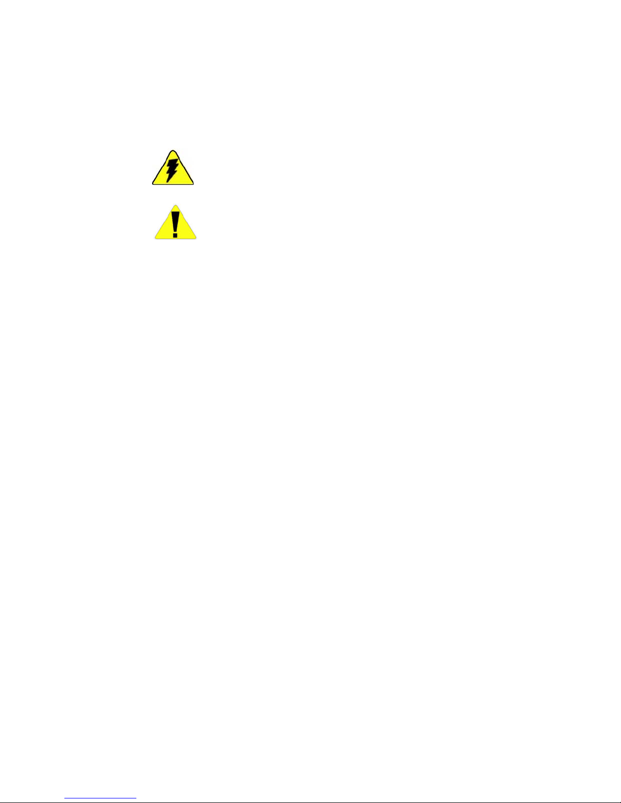
mounted downstream and upstream transducers (refer to Figure 1–1).
Based on the transit time of the two sound waves, the flowmeter calculates
the average fluid velocity.
Thermo Fisher Scientific DCT6088 User Guide 1-1
Figure 1–1. Typical transit time system
Page 16

Product Overview
Transit Time Accuracy
Once the differential transit time is calculated, several additional variables
must be taken into consideration. The overall velocity of the fluid is
comprised of many individual local velocities that vary according to their
distance from the pipe wall. The velocities in the center of the pipe are
higher than the velocities near the pipe wall. The combination of these
individual velocities for a specific type of fluid within a specific pipe yield a
velocity distribution known as the flow profile, which is a function of the
Reynolds number (see Figure 1–2). By properly configuring the flowmeter,
the effects of the flow profile are taken into consideration when calculating
the mean fluid velocity. The flowmeter then multiplies this velocity by the
pipe’s cross-sectional area to obtain volumetric flow.
Transit Time
Accuracy
Figure 1–2. Flow profiles
Non-invasive ultrasonic measurements are subject to a variety of effects that
can influence measurement accuracy. All ultrasonic instruments are velocity
measuring devices and only infer volumetric flow from the operatorentered parameter of pipe inside diameter (ID). When this value is squared
to get cross-sectional area, a 1% error yields a 2% error in volumetric flow.
In practice, commercially fabricated pipe seldom has ID consistency much
tighter than 1%, and unless the pipe to be measured has been accurately
measured, this uncertainty is not reducible through instrument calibration.
The more sophisticated transit time flowmeters incorporate flow profile
corrections to compensate for the pipe’s cross-sectional velocity profile with
a changing Reynolds number. However, this requires the operator to know
the inside roughness of the pipe to be measured. The instrument may infer
a roughness if none is entered by the operator, but that is only an estimate
based on the characteristics of new pipe. Pipes can accumulate deposits that
may reduce the ID and affect the roughness as well. Errors on the order of
2% as a result of this phenomenon are not uncommon.
While other factors may influence instrument accuracy to a lesser extent,
the issues described above are the major elements of pipe dependency upon
absolute instrument accuracy. While calibration on a reference flow loop
under known conditions is a useful exercise to determine the accuracy
potential of an instrument, it is not a guarantee of absolute accuracy on
different pipes under field conditions.
1-2 DCT6088 User Guide Thermo Fisher Scientific
Page 17

Product Overview
Ordering Information
Ordering
Information
The table below provides ordering information for the flowmeter.
1–1.
Table
Code Model
DCT6088 Thermo Scientific DCT6088 dedicated digital correlation transit time flowmeter
Code Power Supply
1 90 to 132 Vac, 50/60 Hz
2 190 to 250 Vac, 50/60 Hz
3 12 to 24 Vdc nominal
Code Output
1 For non-hazardous area use only: One relay, 5 amp, SPDT fully programmable
2 For non-hazardous area use only: Two relays, 5 amp, SPDT fully programmable
3 For non-hazardous area use only: Three relays, 5 amp, SPDT fully programmable
4 For non-hazardous area use only: Four relays, 5 amp, SPDT fully programmable
5 For hazardous area use: One relay, 5 amp, SPDT fully programmable
6 For hazardous area use: Two relays, 5 amp, SPDT fully programmable
7 For hazardous area use: Three relays, 5 amp, SPDT fully programmable
8 For hazardous area use: Four relays, 5 amp, SPDT fully programmable
Code Transmitter Enclosure
1 NEMA 4X
2 NEMA 7
Code Transducer Type (set of two)
S Standard cable (100°C/212°F maximum)
H High temperature cable (200°C/392°F maximum)
Code Transducer Cable (set of two)
030 30 ft (9 m) cable length
XXX Optional standard cable lengths: 50 ft, 75 ft, 100 ft, 150 ft, 200 ft, 300 ft
XXX Optional high temperature cable lengths: 50 ft, 100 ft, 150 ft, 200 ft
Code Transducer Hazardous Area Certification
A Non-hazardous
B CSA: Class I, Div. 2 Groups A, B, C, D or Class II, Div. 2 Groups E, F, G (available
with standard transducer configuration only)
C Barriers to use transducer in CSA Class I, Div. 1 Groups C, D or Class II, Div 1
Groups E, F, G (available with standard transducer configuration only)
Thermo Fisher Scientific DCT6088 User Guide 1-3
Page 18

Product Overview
Specifications
Specifications
Results may vary under different operating conditions.
Table 1–2. Performance specifications
Velocity range ±0 m/s to 15 m/s (±0 ft/s to 50 ft/s)*
Accuracy ±0.5% of velocity or ±0.05 ft/s, typical
Fluids Potable water, ultrapure liquids, deionized water, petroleum
products
Pipe size 25.4 mm to 5 m (1 in to 200 in)*
Contact factory for line sizes smaller than 1 inch.
*Large pieps and high velocities cannot be measured simultaneously.
Table 1–3. Physical specifications
Transmitter IP65, flame retardant, fiberglass reinforced polyester
Transducers Two encapsulated transducers suitable for submersion or
underground service; 9 m (30 ft) standard cable length
Weight Approximately 5.4 kg (12 lb)
Table 1–4. Functional specifications
Outputs 4–20 mA (into 1 to 5 kohms), 12-bit, 5 kV, opto-isolated, loop or
self-powered
RS232 serial interface
Power supply 90 to 132 Vac or 190 to 250 Vac, 50/60 Hz (switch selectable)
12 to 24 Vdc
Temperature range Transducers
Surface: -40°C to 100°C (-40°F to 212°F)
Ambient: -28°C to 80°C (-20°F to 176°F)
Transmitters: -40°C to 60°C (-40°F to 140°F)
Contact factory for higher temperature range requirements.
Keypad 19-key with tactile action
Display 2-line x 40-character, alphanumeric, backlit LCD
Data logger 30,000 point data logger, programmable in 1-second intervals
1-4 DCT6088 User Guide Thermo Fisher Scientific
Page 19

External
Features
Product Overview
External Features
Figure 1–3. External features of the DCT6088
Thermo Fisher Scientific DCT6088 User Guide 1-5
Page 20

This page intentionally left blank.
Page 21

Chapter 2
System Installation
Enclosure
Mounting
Direct Mount
Method
Mounting Ears
Method
The enclosure should be mounted to a sturdy vertical surface such as a wall.
The enclosure can be directly mounted with screws or indirectly mounted
with mounting ears. The flowmeter has 5/16” metal threaded inserts
located in the corners of the enclosure. The inserts are located in mounting
wells that are sealed from the interior of the enclosure when the door is
closed, preventing moisture from entering the instrument through the
mounting holes.
The enclosure can be directly mounted to a wall by inserting four 1/4"
screws into the mounting wells from the front of the enclosure. The screws
act as “through bolts” for securing the unit to the wall.
The enclosure can be mounted to a flat, vertical surface using the optional
mounting ears. The mounting ears can be oriented vertically or
horizontally as follows.
1. Screw the four mounting ears to the metal threaded inserts on the back
of the enclosure using the 5/16” screws provided in the mounting ears
kit.
Thermo Fisher Scientific DCT6088 User Guide 2-1
2. Attach the ears to the wall with standard mounting screws.
Figure 2–1. Mounting ears method
Page 22

System Installation
Transducer Installation
Transducer
Installation
Site Selection &
Preparation
Prior to installing the transducers, a proper site must be selected to ensure
accurate measurement. Examples of site recommendations are illustrated
below.
2-2 DCT6088 User Guide Thermo Fisher Scientific
Figure 2–2. Site recommendations
Page 23

System Installation
Transducer Installation
Use the following guidelines when selecting the transducer site:
● Choose a section of pipe that is always full of liquid, such as a vertical
pipe with up flow or a full horizontal pipe.
● The site should have a straight run equivalent to at least 10 pipe
diameters upstream and 5 pipe diameters downstream from any elbows,
tees, throttling valves, orifices, reduced sections, or other flow
disturbances.
● Up to 30 diameters of straight run may be required upstream from the
flowmeter after a pump, control valve, or double piping bend for
greater accuracy. A distance of 5 diameters downstream is usually
sufficient under all circumstances.
● Always mount the transducers on the sides of the pipe in the 3 o’clock
or 9 o’clock position on horizontal pipes. Positioning the transducers in
this manner prevents signal loss that can be caused by sediment along
the bottom of the pipe or gas bubbles and air pockets along the top of
the pipe.
● Ensure that the pipe skin temperature is within the transducer
temperature rating. The transducers are rated for -40°F to +212°F
(-40°C to +100°C). Temperature ratings up to 392°F (200°C) are
available with optional high temperature transducers.
● Pipes with excessive corrosion or scaling create conditions that can
make accurate measurement difficult or impossible. If possible, avoid
selecting these sections of pipe as mounting locations.
● Remove any dirt, grease, rust, loose paint, or scale from the pipe surface
prior to mounting the transducers. To obtain best results on aging and
rough pipes, a file or grinder may be required to clean the pipe down to
bare metal.
If your application cannot follow these guidelines completely, meaningful
flow measurements (with some loss in accuracy and stability) may still be
obtained, depending on signal quality.
Thermo Fisher Scientific DCT6088 User Guide 2-3
Page 24

System Installation
Spacing & Mounting the Transducers
Spacing &
Mounting the
Transducers
Once you have selected a proper transducer site, you must ensure proper
transducer spacing and mounting in order to maximize signal strength and
accuracy. Do this by following the steps below.
1. Determine the mounting method that is appropriate for your
application: V, W, Z, WW, WV.
2. Refer to Chapter 4 to configure the flowmeter via the keypad or to the
UltraScan manual to configure with the UltraScan software. Note the
value required for the transducer spacing (value calculated by and
displayed on flowmeter LCD or in UltraScan).
3. Clean the area of the pipe designated as the mounting location.
Remove any rust, scale, or loose paint. Well-bonded paint does not
need to be removed.
Note On horizontal pipes, the transducers should be mounted in the 3
o’clock and9 o’clock positions in order to avoid situations that can
cause signal loss, such as sediment along the bottom of the pipe or gas
bubbles or air pockets along the top of the pipe. ▲
4. Apply a wide bead of sonic coupling compound lengthwise down the
center of the face of each transducer.
Note The coupling compound should squeeze out from around the
edges of the transducer when placed against the pipe. There should be
no air gaps between the transducer and the pipe. Refer to “Replacing
Sonic Coupling Compound” (Chapter 7) for instructions on how to
apply sonic coupling co
sonic coupling compounds for high temperature, underground, or
submerged installations. ▲
5. Attach the transducers to the pipe using the stainless steel clamps and
referring to one of the following sections to mount the transducers
according to the selected mounting method: V method, W method, Z
method, or WV and WW methods.
Note The transducers should be mounted on the pipe in relation to the
direction of flow, as shown in the follo
position of the upstream and downstream transducers or reversing the
transducer cable connections to the instrument will result in negative
flow readings.
▲
mpound and for information on using other
wing figure. Reversing the
2-4 DCT6088 User Guide Thermo Fisher Scientific
Page 25

System Installation
Spacing & Mounting the Transducers
Figure
2–3.
6. Tighten both straps securely. Ensure the transducer face is aligned
normal to the pipe. The transducer face alignment is particularly
critical on small pipes due to pipe curvature. In the figure below, notice
that the properly installed transducer contacts the pipe at the pipe’s
centerline and that the gaps on either side of the centerline are equal.
Follow these steps for the easiest method of aligning transducers on
small pipes:
a. Secure both transducers to the pipe with pipe clamps, and tighten
the clamps until the transducers fit snugly.
b. Adjust the transducers until the gaps on both sides are equal.
c. While holding the transducers in place, tighten the clamps
sufficiently to prevent the transducers from slipping and to allow
proper flowmeter operation.
Figure 2–4.
Thermo Fisher Scientific DCT6088 User Guide 2-5
Page 26

System Installation
Spacing & Mounting the Transducers
7. The transducer cables connect to the terminal block labeled
TRANSDUCERS.
Note The upstream transducer cable has red-banded ends, and the
downstream transducer cable has blue-banded ends. ▲
Note Refer to Chapter 8 for information on connecting the transducer
cables in hazardous area applications. ▲
Connect the transducer cables to the flowmeter as follows:
a. Connect the center wire of downstream transducer cable to the
XMT (DN) terminal.
b. Connect the braided shield wire of downstream transducer cable to
the XMT GND terminal.
c. Connect the center wire of upstream transducer cable to the RCV
(UP) terminal.
d. Connect the braided shield wire of upstream transducer cable to the
RCV GND terminal.
8. If maximum accuracy at low flow rates is important, calibrate the
flowmeter according to “The Calibration Menu” (Chapter 5).
The flowmeter is now capable of accurately measuring velocity and flow.
2-6 DCT6088 User Guide Thermo Fisher Scientific
Page 27

System Installation
W
Transducer Mounting Methods
Transducer
Mounting
Methods
V Method
There are several methods of mounting the transducers. The best method is
determined by the specific application. Complete steps 1–5 in previous
section, and then refer to the following sections for instructions on how to
properly mount the transducers using one of the available mounting
methods.
The V method is considered the standard method for pipes with diameters
of 4 to 16 inches (101.6 to 406.4 mm). This method typically yields a
more accurate reading than the Z method since it utilizes a longer
measurement path. When configuring the flowmeter, ensure V is the
selected mounting method.
Method
Figure 2–5. V mounting method
In many instances, flowmeter performance on small metallic pipes with
outer diameters of 4 inches (100 mm) or less can be improved by using the
W mounting method. With the W method, the sound wave traverses the
fluid four times and bounces off the pipe walls three times. Like the V
method, both transducers are mounted on the same side of the pipe. When
configuring the flowmeter, ensure W is the selected mounting method.
Figure 2–6. W mounting method
Thermo Fisher Scientific DCT6088 User Guide 2-7
Page 28
System Installation
Transducer Mounting Methods
Z Method
The signal transmitted in a Z method installation has less attenuation than
a signal transmitted with the V method. This is because the Z method
utilizes a directly transmitted (rather than reflected) signal that transverses
the liquid only once. The Z method is used primarily in applications where
the V method cannot work due to signal attenuation from excessive air or
solids in the liquid, thick scale, poorly bonded linings, or very large pipes.
In addition, the Z method generally works better on larger diameter pipes
where less pipe length is required for mounting.
Figure 2–7. Z mounting method
To mount the transducers using the Z mounting method, follow the steps
below.
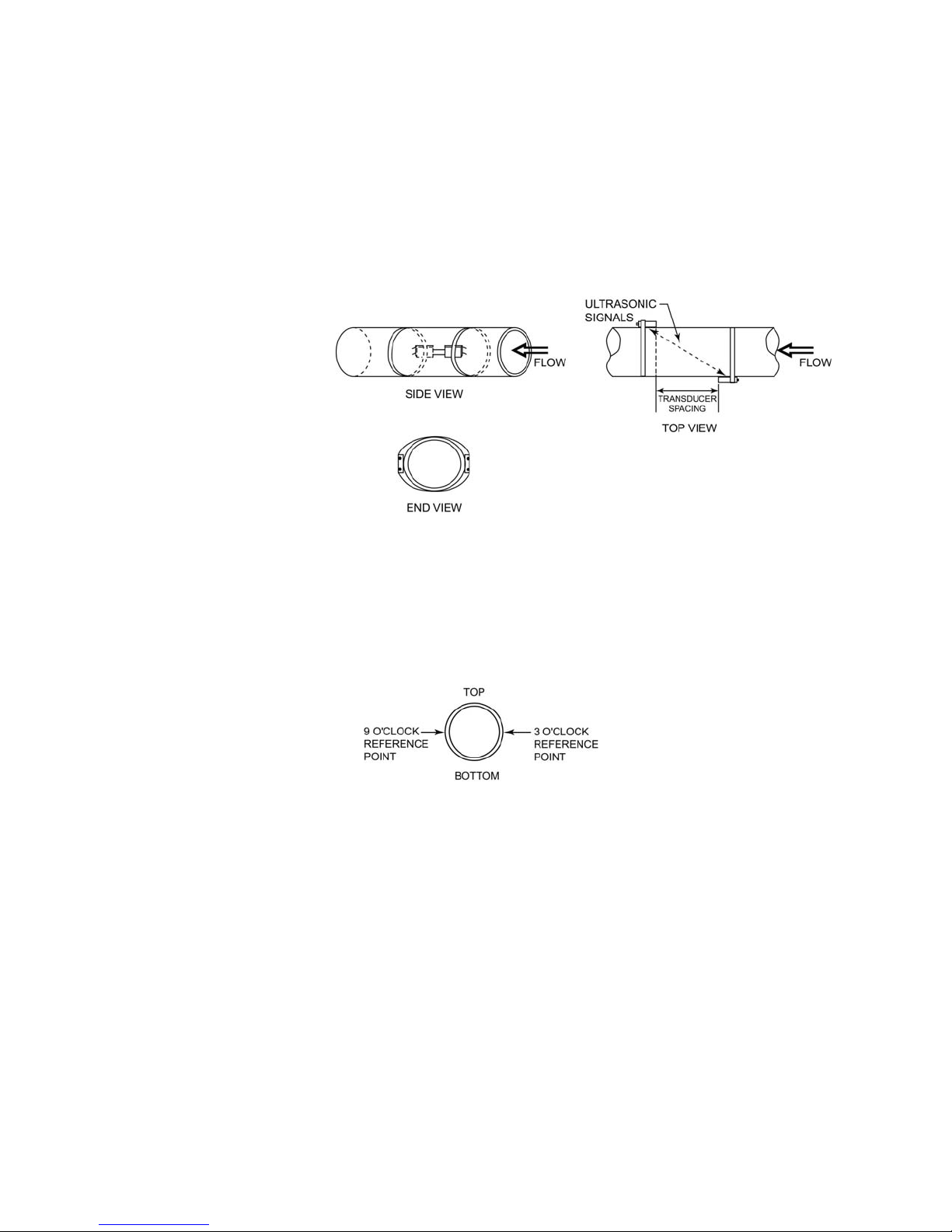
1. Establish a reference at the 3 o’clock and 9o’clock positions on the
pipe.
Figure 2–8. Z mounting method, step 1
2. Place a transducer at the 3 o’clock position.
3. Trace the shape of the 3 o’clock transducer along its inside edge
(opposite the cable connection). Draw a horizontal line at its center.
Remove the transducer.
2-8 DCT6088 User Guide Thermo Fisher Scientific
Page 29

System Installation
Transducer Mounting Methods
Figure 2–9. Z mounting method, steps 2–3
4. Obtain a continuous sheet of paper longer than the circumference of
the pipe. Calculator paper tape or thermal printer paper works well for
this.
5. Fold one end of the paper across the pipe’s width to produce a clean,
straight edge.
6. Line the fold of the paper up with the horizontal centerline of the 3
o’clock transducer.
Figure 2–10. Z mounting method, steps 4–6
7. Wrap the paper firmly around the pipe, and mark the intersection
point where the fold comes in contact with the rest of the paper.
Figure
2–11. Z mounting method, step 7
Thermo Fisher Scientific DCT6088 User Guide 2-9
Page 30
System Installation
Transducer Mounting Methods
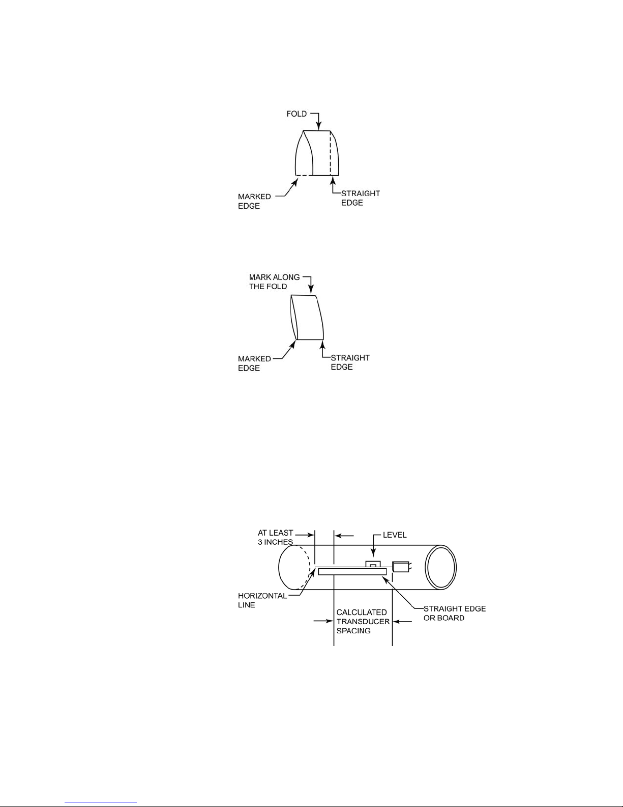
8. Remove the paper from the pipe. Place the fold and intersection mark
together again, and fold the paper exactly in half.
Figure 2–12. Z mounting method, step 8
9. Mark along the new fold.
Figure 2–13. Z mounting method, step 9
10. Draw a horizontal line along the pipe from the centerline of the 3
o’clock transducer position. Use a level to ensure that the line is level
with the top of the pipe. The line should be at least 3 inches (76 mm)
longer than the transducer spacing calculated by the UltraScan software
or via menu 25.
For example, if the software calculates the spacing as 14 inches (356
mm), draw a line 17 inches (432 mm) long.
Figure
2–14. Z mounting method, step 10
2-10 DCT6088 User Guide Thermo Fisher Scientific
Page 31

System Installation
Transducer Mounting Methods
11. Measure the spacing from the inside edge of the 3 o’clock transducer,
and mark this on the pipe.
Figure 2–15. Z mounting method, step 11
12. Wrap the paper firmly back on the pipe. Have the point where the ends
of the paper come together line up with the horizontal line on the 3
o’clock side of the pipe. Ensure that the inside corner of the straight
edge of the paper is aligned with the mark made for the transducer
spacing. Tape the paper down, or have someone hold the paper in
place.
Figure
2–16. Z mounting method, step 12
13. Go to the other side of the pipe (9 o’clock position), and mark the pipe
at the point where the marked fold and the inside edge of the paper
length intersect.
Figure 2–17. Z mounting method, step 13
Thermo Fisher Scientific DCT6088 User Guide 2-11
Page 32

System Installation
W
Transducer Mounting Methods
14. Remove the paper from the pipe and trace the shape of the 9 o’clock
transducer in the same manner you did for the 3 o’clock transducer.
Ensure that the inside edge of the transducer (opposite the cable
connection) is even with the point just marked on the 9o’clock side of
the pipe.
Figure 2–18. Z mounting method, step 14
15. Mount the transducers with pipe straps by following steps 5-6 in
“Spacing & Mounting the Transducers” earlier in this chapter.
V and WW
Methods
Figure 2–19. Z mounting method, step 15
The figure below illustrates the final Z method installation.
Figure 2–20.
For applications with pipe diameters smaller than 2 inches (50 mm), the
WV and WW methods are options that allow higher accuracy and stability
to be achieved when reasonable signal strength can be obtained (10% or
higher).
2-12 DCT6088 User Guide Thermo Fisher Scientific
Page 33

System Installation
Small Pipe Applications
Small Pipe
Applications
In this section, small pipe applications refer to the following pipe sizes:
● Stainless steel or brass: 1.0 to 3.5 inches (25.4 to 88.9 mm)
● PVC, carbon steel, or other: 1.0 to 2.5 inches (25.4 to 63.5 mm)
If signal strength is greater than 10%, we recommend the W mounting
method for pipe sizes 3.5 inches (63.5mm) or smaller and the WW
mounting method for pipe sizes 2.0 inches (50.8 mm) or smaller.
The pipe curve effect on small pipe applications can cause multipath signals
and measurement uncertainty. Removing extra compound along the
transducer sides can eliminate the side wave paths as seen in Figure 2–21
below.
To eliminate these side wave paths, apply coupling compound as usual on
to the coupling surfaces, and clamp the transducers onto the pipe. Use a
pen-sized, standard screwdriver to remove the extra grease between the
transducers and the pipe.
Figure 2–21. Effect of extra compound on small pipes
For high temperature or outdoor small pipe applications, use the foam tape
strips shipped with the flowmeter to block the side wave paths. Other tape
materials generally do not satisfy performance or safety specifications.
Please contact Thermo Fisher when more tape strips are needed.
Apply the foam tape strips according to the steps below.
1. Wipe grease off the coupling surfaces of both transducers. Clean the
surfaces with detergent and let dry.
2. Draw two lines on each transducer surface with a pencil so that the
band defined by the lines is in the middle of the surface. The spacing
between the two lines should be as shown in the following table.
Thermo Fisher Scientific DCT6088 User Guide 2-13
Page 34

System Installation
Small Pipe Applications
Table 2–5.
Pipe Sizes Spacing
3.0 to 3.5 inches (76.2 to 88.9 mm) 0.50 inches (12.7 mm)
2.5 to 3.0 inches (63.5 to 76.2 mm) 0.44 inches (11.2 mm)
2.0 to 2.5 inches (50.8 to 63.5 mm) 0.38 inches (9.7 mm)
1.5 to 2.0 inches (38.1 to 50.8 mm) 0.32 inches (8.13 mm)
1.5 inches (38.1 mm ) and smaller 0.25 inch (6.35 mm)
Figure 2–22.
3. Remove the adhesive protection paper to expose the tape strips. Place a
strip on each side of the surface along the line. Press the strips down to
ensure good adhesion.
Figure
2–23.
4. Apply coupling compound to the space between the tape strips. The
optimum height of the compound layer is approximately half the
height of the tape strips.
2-14 DCT6088 User Guide Thermo Fisher Scientific
Figure 2–24.
Page 35

Chapter 3
Wiring
Cable Routing able Routing
Warning Avoid potential injury or damage to equipment. Ensure the
flowmeter is grounded at ALL times. ▲
Warning Minimize the possibility of explosion in hazardous areas. Do not
disconnect power until the area is known to be non-hazardous. ▲
Warning Prevent the possibility of electrical shock or damage to the
instrument. Disconnect power prior to removing the sheet metal access
cover. Replace the cover before reconnecting power to the unit. ▲
Warning All wiring should be routed through conduit or cable glands to
seal the enclosure. Refer to Figure 3–1 for the recommended cable routing.
Bonding between conduit connections is not automatic and must be
provided as part of the installation. ▲
Thermo Fisher Scientific DCT6088 User Guide 3-1
Page 36

Wiring
Power Connections
Figure 3–1. Recommended cable routing
Power
ower
Connections
Connections
Warning To prevent damage to the instrument, verify that the voltage to
be connected matches the voltage rating of the flowmeter. The voltage
rating is indicated beneath the power input terminals. ▲
Warning Power connections must be made in accordance with local
standards or codes of practice. ▲
The power input terminals shown in Figure 3–1 can be connected to one
of the following voltages:
● 120 Vac, 50/60 Hz (setting should be on 110)
● 240 Vac, 50/60 Hz (setting should be on 220)
● 12 to 24 Vdc (setting should be on 110)
To connect power, remove the sheet metal access cover. Locate the
individual power input terminals. They are marked directly on the main
board or on a sticker attached to the main board. Connect the power
according to one of the following sections.
3-2 DCT6088 User Guide Thermo Fisher Scientific
Page 37

Wiring
Power Connections
120 Vac Operation
Single Phase 240
Vac Operation
To connect the power for 120 Vac operation:
1. Connect the hot wire to the L1(+) terminal.
2. Connect the neutral wire to the L2/N(-) terminal.
3. Connect the ground wire to the GND terminal.
To connect the power for single phase 240 Vac operation:
1. Connect the live wire to the L1(+) terminal.
2. Connect the neutral wire to the L2/N(-) terminal.
3. Connect the ground wire to the GND terminal.
Double Phase 240
Vac Operation
12 to 24 Vdc
Operation
To connect the power for double phase 240 Vac operation:
1. Connect the one hot wire to the L1(+) terminal.
2. Connect the other hot wire to the L2/N(-) terminal.
3. Connect the ground wire to the GND terminal.
Note For DC operation, set the 4 –20 mA current loop function to loop
powered mode to prevent ground loops.
To connect the power for 12 to 24 Vdc operation:
4. Connect the positive wire to the L1(+) terminal.
▲
Thermo Fisher Scientific DCT6088 User Guide 3-3
5. Connect the negative wire to the L2/N(-) terminal.
Page 38

Wiring
The Current Loop
The Current Loop
The 4–20 mA current loop module has an input terminal and an output
terminal, which are indicated on a label on the inside of the flowmeter
door. The current loop output is rated for a loop resistance of up to 1
kohm and is isolated for up to 5 kV when loop-powered.
The 4–20 mA module is shipped in the self-powered configuration. Switch
to loop power by moving a jumper on the module. Current loop modules
that are loop powered must be driven from an external power supply. In
this case the flowmeter acts as a passive two-wire transmitter.
Warning Prevent the possibility of electrical shock or damage to the
instrument. Disconnect power prior to making connections or changing
the loop configuration. ▲
To connect the current loop:
1. Ensure the loop powering option is correct. Locate the jumpers on the
upper right corner of the module. Refer to the figure below to change
the jumper settings.
3-4 DCT6088 User Guide Thermo Fisher Scientific
Figure 3–2. Jumper settings for current loop configurations
Page 39

Wiring
Relay Terminals
2. Refer to the self-powered or loop powered configuration figure below
for wiring.
Figure 3–3. Self-powered current loop configuration
Relay Terminals
Figure 3–4. Loop powered current loop configuration
Up to four relays may be installed in the instrument. The relays are rated at
5 A, 250 Vac. Each relay contains a normally open and normally closed dry
contact accessible at the terminal blocks. The terminals for the relay are
labeled on the module as NO (normally open), C (common), and NC
(normally closed). When the relay is energized, the C terminal is shorted to
the NO terminal (refer to Figure 3–5). When the relay is at rest, the C
terminal is shorted to the NC terminal.
Thermo Fisher Scientific DCT6088 User Guide 3-5
Figure
3–5. Relay schematic
Page 40

Wiring
Communications Terminal Block
The terminal blocks for the relays are labeled on the board as RELAY 1
through RELAY 4. The relay terminal blocks should be wired for either
NO or NC circuits. Figure 3–6 shows RELAY 1 is wired for a NC circuit.
Figure 3–6. Relay terminal block
Note The auxiliary terminal block is for future development. ▲
Communications
Terminal Block
Transducer
Wiring
The communications terminal block is for future development.
The transducer terminals and cables are arranged in pairs and are labeled
DN STREAM and UPSTREAM. The downstream transducer cable has
blue-banded ends, and the upstream transducer has red-banded ends.
Refer to the figure below. The symbol is on both pairs of terminals and
indicates which terminals should connect to the center wire conductors and
which should connect to the coaxial shields.
Figure 3–7.
3-6 DCT6088 User Guide Thermo Fisher Scientific
Page 41

Chapter 4
Operating & Configuring the
Flowmeter
The Keypad &
Display
Figure 4–1. Keypad & display
Adjusting the
Contrast
Interface with the instrument is via the keypad. During operation, the
LCD indicates flow rate and totalizer values. The display is also backlit for
ease of viewing in low-light conditions and has a variable contrast setting.
You may need to adjust the contrast on the display as ambient temperature
changes. Follow the steps below to do so.
Thermo Fisher Scientific DCT6088 User Guide 4-1
1. Press MENU followed by the +/- (plus/minus) key.
2. LCD CONTRAST appears on the display with a bar the indicating
current contrast setting.
3. Press the left or right arrows to adjust the contrast.
4. Press ENTER when complete.
Page 42

Operating & Configuring the Flowmeter
Flowmeter Configuration
Flowmeter
Configuration
Direct Menu Access
Flowmeter configuration is accomplished using the setup menus. Some
setup menus allow a numeric value to be entered, and others offer nonnumeric selections. In non-numeric setup menus, an asterisk is displayed to
the left of the selected currently entered in the flowmeter, as shown in the
figure below.
Figure 4–2.
There are two ways to access the setup menus: via direct access or through
the menu structure.
The unique two-digit address for each setup and diagnostic menu enables
the user to directly access the desired menu. The menu addresses are listed
in Table 4–1. To use them, follow the two steps below.
1. Press MENU, and the letter M appears in the lower right corner of the
display.
2. Enter the desired two-digit address.
Note The address must be entered while the M is displayed (within
approximately 4 seconds). If the M is no longer displayed, press
MENU again followed by the two-digit address. ▲
3. If the setup menu requires a numeric entry, use the numeric keys to
enter the value and press ENTER to accept the value. If you need to
change the entry, press ERASE. If the setup menu offers a non-numeric
selection, press ENTER, and the asterisk changes to a flashing cursor.
Use the arrow keys to scroll through the available selections. When the
cursor is to the left of the desired selection, press ENTER.
4. Complete the process by accessing a Primary display (menus 00
through 04).
Note The flowmeter will not use the new parameters until you access a
Primary display. ▲
4-2 DCT6088 User Guide Thermo Fisher Scientific
Page 43

Operating & Configuring the Flowmeter
Flowmeter Configuration
Table 4–1. Menu addresses
Menu Type Display Address
Primary Flow/Net Totalizer 00
Flow/Velocity 01
Flow/Positive Totalizer 02
Flow/Negative Totalizer 03
Signal Strength/Low Signal Cutoff 04
Pipe Pipe OD 10
Pipe Wall Thickness 11
Pipe ID 12
Pipe Material 13
Pipe Sound Speed 14
Pipe Inside Roughness 15
Liner Liner Material 16
Liner Thickness 17
Liner Sound Speed 18
Liner Inside Roughness 19
Fluid Fluid Type 20
Fluid Sound Speed 21
Fluid Viscosity 22
Transducer Transducer Type 23
Transducer Mounting 24
Transducer Spacing 25
Flow Flow Units 30
Max Flow Range 31
Min Flow Range 32
Damping 33
Low Flow Cutoff 34
Low Signal Cutoff 35
Totalizer Totalizer Units 36
Thermo Fisher Scientific DCT6088 User Guide 4-3
Totalizer Multiplier 37
Net Totalizer 38
Positive Totalizer 39
Negative Totalizer 40
Page 44

Operating & Configuring the Flowmeter
Flowmeter Configuration
Menu Type Display Address
Totalizer Reset 41
Options Measurement Units 42
Site Parameters 43
RS232 Configuration 46
Change System Password 47
Change Scale Factor Password 48
Unit ID 49
Calibration 50
Zero Set 51
Scale Factor 52
Sound Speed Compensation 53
Date and Time 54
Current Loop 56
Current Loop Span 57
Current Loop Calibration 58
Current Loop Test 59
Relays 70
Program Relays 71
View Relays 72
Test Relays 73
Datalog 80
Datalog Interval 81
Diagnostics Signal Strength/Margin 90
Delta Time/Fluid Sound Speed 91
Reynolds#/Profile Factor 92
Current Loop Output 93
Software/Firmware Rev. Level 94
4-4 DCT6088 User Guide Thermo Fisher Scientific
Page 45

Operating & Configuring the Flowmeter
Flowmeter Configuration
Using the Arrow
Keys to Access
Menus
The other method of accessing the flowmeter menus is to use the left and
right arrows to scroll through the menu structure. Menus are organized
into three basic levels:
● Main menu
● Submenus
● Primary displays, setup menus, diagnostic menus.
The Main menu displays various submenus that contain individual setup
and diagnostic menus. Following is an example of how to use the arrow
keys to access the Main menu from any screen.
1. Press MENU twice. The Main menu is displayed with the Pipe and
Line submenu options.
Figure 4–3. The Main menu
2. To view the remaining submenus, press the down arrow.
Figure 4–4. Remaining submenus of the Main menu
3. When the desired submenu is highlighted, press ENTER to display the
first menu of the selected submenu. The figure below shows what is
displayed if the Flow submenu is selected.
Thermo Fisher Scientific DCT6088 User Guide 4-5
Figure 4–5.
Page 46

Operating & Configuring the Flowmeter
Quick Setup Configuration
4. If the setup menu requires a numeric entry, use the numeric keys to
enter the value and press ENTER to accept the value. If you need to
change the entry, press ERASE. If the setup menu offers a non-numeric
selection, press ENTER, and the asterisk changes to a flashing cursor.
Use the arrow keys to scroll through the available selections. When the
cursor is to the left of the desired selection, press ENTER.
5. Complete the process by accessing a Primary display (menus 00
through 04).
Note The flowmeter will not use the new parameters until you access a
Primary display. ▲
Quick Setup
Configuration
The quick setup procedure contains the minimal steps required for
flowmeter configuration. These steps enable the flowmeter to calculate
transducer spacing, acquire ultrasonic signal, and measure flow. The
number in parentheses after the required menu is the two-digit address to
directly access that menu.
1. Select a proper transducer site according to “Site Selection &
Preparation” in Chapter 2.
2. Access the Pipe submenu. This submenu contains setup menus related
to the pipe parameters such as pipe inside diameter (ID) and pipe
outside diameter (OD).
Note Pipe Wall Thickness is an additional setup menu within the Pipe
submenu. If values for two of the following setup menus are entered,
the flowmeter will calculate the remaining parameter automatically:
Pipe OD (10), Pipe Wall Thickness (11), Pipe ID (12). ▲
Note Accuracy is directly affected by the square of an error in pipe
dimensions. Actual measurements (not nominal) must be entered. ▲
4-6 DCT6088 User Guide Thermo Fisher Scientific
a. Select the PIPE OD menu (10). The screen shown in Figure 4–6 is
displayed. Enter the value for the pipe OD and press ENTER.
Press the down arrow, and select Actual.
Page 47

Operating & Configuring the Flowmeter
Quick Setup Configuration
Figure 4–6. Pipe OD menu
If you know the pipe circumference but not the OD, enter the
circumference value instead and press ENTER and the down
arrow. The screen shown in Figure 4–7 is displayed. Select Circum.
The flowmeter will calculate the pipe OD automatically.
Figure 4–7. Pipe OD type options
b. Select the Pipe ID setup menu (12), and enter the pipe ID. Press
Enter.
Figure 4–8. Pipe ID setup menu
c. Select the Pipe Material setup menu (13). Press the up or down
arrow to scroll through the available options.
Note Select OTHER if the material is not listed. You must then
enter the pipe sound speed (14) and pipe inside roughness (15). ▲
Figure
4–9. Pipe Material setup menu
Note Refer to “The Pipe Menu” (Chapter 5) for additional items not
addressed in the quick setup procedure.
▲
3. If there is a liner, continue with this step. Otherwise, skip to step 4.
Thermo Fisher Scientific DCT6088 User Guide 4-7
a. Access the Liner Material setup menu (16). The screen shown in
Figure 4–10 is shown. Select one of the available options.
Page 48

Operating & Configuring the Flowmeter
Quick Setup Configuration
Note Select OTHER if the material is not listed. You must then
enter the liner sound speed (18) and liner inside roughness (19). ▲
Figure 4–10. Liner Material setup menu
b. Access the Liner Thickness setup menu (17), and enter the
thickness.
Figure
4–11. Liner Thickness setup menu
Note Refer to “The Liner Menu” (Chapter 5) for additional items not
addressed in the quick setup procedure.
▲
4. Access the Fluid Type setup menu (20), and select one of the available
options.
Note Select OTHER if the fluid type is not listed. You must then
enter the fluid sound speed (21) and fluid viscosity (22). ▲
Figure 4–12. Fluid Type setup menu
Note Refer to “The Fluid Menu” (Chapter 5) for additional items not
addressed in the quick setup procedure.
▲
4-8 DCT6088 User Guide Thermo Fisher Scientific
Page 49

Operating & Configuring the Flowmeter
Quick Setup Configuration
5. Enter the Transducer submenu.
a. Access the Transducer Type setup menu (23). Currently, the only
selection available is Standard. Standard must be selected for all
applications using clamp-on transducers, including high
temperature transducers.
Figure
4–13. Transducer Type setup menu
b. Access the Transducer Mounting setup menu (24), and select the
desired mounting method.
Figure 4–14. Transducer Mounting setup menu
6. Access the Transducer Spacing view-only menu (25). Note the required
spacing between transducers.
Figure 4–15. Transducer Spacing menu
7. Enter the Flow submenu, and access the Flow Units setup menu (30).
Select the flow rate units.
a. Select one of the available volumetric units.
Figure 4–16. Flow Units setup menu
Thermo Fisher Scientific DCT6088 User Guide 4-9
Page 50

Operating & Configuring the Flowmeter
Quick Setup Configuration
b. Press the down arrow and the Flow Units Per options are
displayed. Select the desired option.
Figure 4–17. Flow Units Per setup menu
Note Refer to “The Flow Menu” (Chapter 5) for additional items not
addressed in the quick setup procedure. ▲
8. Install the transducers on the pipe using the spacing provided by the
flowmeter, and connect the transducer cables to the flowmeter.
9. Access a Primary Display (00 through 04) to complete the
configuration process.
If the flowmeter and transducers are properly installed and a steady flow is
present, the flow and signal strength readings should be relatively stable.
Note If any of the above setup parameters are changed, the flowmeter stops
measuring flow until the new value is entered and a Primary Display is
accessed to accept the new value. ▲
4-10 DCT6088 User Guide Thermo Fisher Scientific
Page 51

Chapter 5
Primary Displays & Menus
Primary Displays
Flow/Net Totalizer
Flow/Velocity
The primary displays are for viewing only and cannot be configured.
Primary displays are menus 00 through 04 and display values for flow rate,
totalizers, velocity, signal strength, or low signal cutoff.
The Flow/Net Totalizer primary display (00) is the standard display used
under normal operating conditions. It displays the flow rate and net
totalizer value. If the net totalizer is not currently enabled, the last net
totalized value is displayed.
Figure 5–1. Flow/Net Totalizer primary display
The Flow/Velocity primary display (01) indicates the flow rate and fluid
velocity. Velocity is displayed in feet per second (FPS) if English is selected
as the measurement unit (menu 42) and in meters per second (MPS) if
Metric is selected.
Flow/Positive
Totalizer
Thermo Fisher Scientific DCT6088 User Guide 5-1
Figure
The Flow/Positive Totalizer primary display (02) indicates the flow rate
and the totalized flow in the positive flow direction. If the positive totalizer
is not currently enabled, the last net totalized value is displayed.
Figure
5–2. Flow/Velocity primary display
5–3. Flow/Positive Totalizer primary display
Page 52

Primary Displays & Menus
The Pipe Menu
Flow/Negative
Totalizer
Signal Strength/Low
Signal Cutoff
The Pipe Menu
The Flow/Negative Totalizer primary display (03) indicates the flow rate
and the totalized flow in the negative flow direction. If the negative
totalizer is not currently enabled, the last net totalized value is displayed.
Figure
5–4. Flow/Negative Totalizer primary display
The Signal Strength/Low Signal Cutoff primary display (04) indicates the
values for signal strength and low signal cutoff.
Figure 5–5. Signal Strength/Low Signal Cutoff primary display
The Pipe menu contains additional items that are not included in the quick
setup procedure described in Chapter 4. These items are listed below.
● Pipe Wall Thickness setup menu (11)
Figure 5–6. Pipe Wall Thickness setup menu
● Pipe Sound Speed setup menu (14)
This menu can only be configured if OTHER was selected as the pipe
material (13). Enter the pipe sound speed. If OTHER was not selected
as the pipe material, this menu is available by the direct access method
only and functions as a view-only display to indicate the pipe sound
speed as programmed in the instrument’s database.
Figure 5–7. Pipe Sound Speed setup menu
5-2 DCT6088 User Guide Thermo Fisher Scientific
Page 53

Primary Displays & Menus
The Liner Menu
● Pipe Inside Roughness setup menu (15)
This menu can only be configured if OTHER was selected as the pipe
material (13). Data on this parameter are available from the Cameron
Hydraulic Data Book published by Ingersoll-Rand. Enter the inside
roughness of the pipe. If OTHER was not selected as the pipe material,
this menu is available by the direct access method only and functions as
a view-only display to indicate the pipe inside roughness as
programmed in the instrument’s database.
Figure 5–8. Pipe Inside Roughness setup menu
The Liner Menu
The Liner menu contains additional items that are not included in the
quick setup procedure described in Chapter 4. These items are listed below.
● Liner Sound Speed setup menu (18)
This menu can only be configured if OTHER was selected as the liner
material (16). Enter the liner sound speed. If OTHER was not selected
as the liner material, this menu is available by the direct access method
only and functions as a view-only display to indicate the liner’s sound
speed as programmed in the instrument’s database.
Figure
● Liner Inside Roughness setup menu (19)
5–9. Liner Sound Speed setup menu
This menu can only be configured if OTHER was selected as the liner
material (16). Enter the liner inside roughness. If OTHER was not
selected as the liner material, this menu is available by the direct access
method only and functions as a view-only display to indicate the inside
roughness of the liner as programmed in the instrument’s database.
Thermo Fisher Scientific DCT6088 User Guide 5-3
Figure 5–10. Liner Inside Roughness setup menu
Page 54

Primary Displays & Menus
The Fluid Menu
The Fluid Menu
The Fluid menu contains additional items that are not included in the
quick setup procedure described in Chapter 4. These items are listed below.
● Fluid Sound Speed setup menu (21)
This menu can only be configured if OTHER was selected as the fluid
type (20). Enter the fluid sound speed. If OTHER was not selected as
the fluid type, this menu is available by the direct access method only
and functions as a view-only display to indicate the fluid sound speed as
programmed in the instrument’s database.
Figure 5–11. Fluid Sound Speed setup menu
● Fluid Viscosity setup menu (22)
This menu can only be configured if OTHER was selected as the fluid
type (20). Enter the fluid viscosity. If OTHER was not selected as the
fluid type, this menu is available by the direct access method only and
functions as a view-only display to indicate the fluid viscosity as
programmed in the instrument’s database.
Figure 5–12. Fluid Viscosity setup menu
5-4 DCT6088 User Guide Thermo Fisher Scientific
Page 55

Primary Displays & Menus
The Flow Menu
The Flow Menu
The Flow menu contains additional items that are not included in the
quick setup procedure described in Chapter 4. These items are listed below.
● Max Flow Range (31) and Min Flow Range (32) setup menus
Use these menus to enter the minimum and maximum flow values for
setting the volumetric flow range. Setting the optimum flow range
generally improves response time.
Figure
5–13. Max Flow Range setup menu
Figure 5–14. Min Flow Range setup menu
Note Whenever the pipe ID is changed, the flowmeter returns the
volumetric flow range to default settings. The default settings are the
maximum and minimum flows for the new pipe ID that occur at +32
and -32 ft/s (+9.76 and -9.76 m/s). ▲
● Damping setup menu (33)
Use this menu to enter the value for the damping coefficient, which
suppresses short-term fluctuations in the indicated flow rate. The
displayed flow rate and the 4–20 mA current loop output is a moving
average of the last n seconds where n is the damping value. Increasing
the coefficient increases the response time to changes. The coefficient is
adjustable from 1 to 99 seconds in1-second increments. Damping
should be kept at a minimum unless the flow rate fluctuates wildly. If
this is the case, increase the damping coefficient just enough to reduce
the fluctuation to an acceptable degree.
Figure 5–15. Damping setup menu
Thermo Fisher Scientific DCT6088 User Guide 5-5
Page 56

Primary Displays & Menus
The Flow Menu
● Low Flow Cutoff setup menu (34)
When a zero flow condition occurs (for example, as the result of a
pump being shut off), internal sloshing, check valve leakage, and other
fluid movement can prevent the flowmeter from reading total zero.
This phenomenon can result in totalizer errors. Minimize these errors
by entering a low flow cutoff, which drives the flowmeter to zero for
flow rates at or below the specified value. If the flow rate falls below the
low flow cutoff value, the indicated flow rate is driven to zero and the
totalizers stop incrementing. This is the case regardless of flow
direction.
Figure 5–16. Low Flow Cutoff setup menu
For example, if you enter a low flow cutoff of 0.1 ft/s (0.03 m/s), the
flowmeter will be driven to zero for flow rates less than 0.1 ft/s in the
positive direction and greater than -0.1 ft/s in the negative direction.
Figure 5–17.
● Low Signal Cutoff setup menu (35)
Empty pipes or solids, bubbles, or voids in the flow stream may cause
temporary drops in signal strength and erroneous readings. Minimize
the effect of these dropouts by setting a low signal cutoff, which drives
the flowmeter to the loss-of-signal (LOS)condition. The low signal
cutoff should be set at the minimum acceptable signal amplitude.
To set the low signal cutoff, access the Low Signal Cutoff setup menu
(35). Enter the low signal cutoff and press ENTER.
Figure 5–18. Low Signal Cutoff setup menu
5-6 DCT6088 User Guide Thermo Fisher Scientific
Page 57

Primary Displays & Menus
The Total Menu
Note The value for the low signal cutoff should usually be set at
approximately half of the value of the signal strength present under
flow conditions. Typically, signal strength is not significantly affected
by flow rate. ▲
From the Low Signal Action setup menu, select one of the following:
● Zero: The flowmeter drops the reading to zero during LOS
condition.
● Hold: The flowmeter holds the last valid reading during LOS
condition for about three seconds.
Figure 5–19. Low Signal Action setup menu
The Total Menu
Access the Total menu to configure the totalizer parameters.
● Totalizer Units setup menu (36)
The flow units elected for the totalizer display may be different from
the flow unit selected for the flow rate display.
Figure 5–20. Totalizer Units setup menu
● Totalizer Multiplier setup menu (37)
The totalizer value can be displayed with one of several multiplier
values. For example, 700 liters can be displayed as ‘700’ if the selected
multiplier value is X1, or it can be displayed as ‘7’ if the selected
multiplier value is X100.
Figure 5–21. Totalizer Multiplier setup menu
Thermo Fisher Scientific DCT6088 User Guide 5-7
Page 58

Primary Displays & Menus
The Total Menu
● Net Totalizer setup menu (38)
Use this menu to enable or disable the net totalizer. The net totalizer
provides the difference between the positive and negative flow values.
For example, if there are 1,000 gallons of flow in the negative direction
and 3,000 gallons of flow in the positive direction, the net totalizer
indicates 2,000 gallons of net flow.
Figure 5–22. Net Totalizer setup menu
● Positive Totalizer setup menu (39)
Use this menu to enable or disable the positive totalizer. The positive
totalizer tracks the flow that moves in the positive direction, from
upstream transducer to downstream transducer. It is not affected by
flow in the opposite direction.
Figure 5–23. Positive Totalizer setup menu
● Negative Totalizer setup menu (40)
Use this menu to enable or disable the negative totalizer. The negative
totalizer tracks the flow that moves in the negative direction, from
downstream transducer to upstream transducer. It is not affected by
flow in the opposite direction.
Figure 5–24. Negative Totalizer setup menu
● Totalizer Reset menu (41)
Use this menu to reset one or all of the totalizers.
Figure
5–25. Totalizer Reset menu
5-8 DCT6088 User Guide Thermo Fisher Scientific
Page 59

Primary Displays & Menus
Options Menu
Options Menu
The Options submenu contains setup menus for several miscellaneous
functions.
● Measurement Units setup menu (42)
Use this menu to select English (feet per second, FPS) or Metric
(meters per second, MPS) measurement units.
Figure 5–26. Measurement Units setup menu
● Site Parameters setup menu (43)
This menu saves the parameters for the pipe, liner, fluid, transducer,
and flow setup menus, allowing them to be recalled later for a specific
measurement site. Several sites are available and are numbered. The site
number is displayed in the lower left corner of the screen and is
followed by a colon. An example of a site numbered 1 is shown below.
Figure 5–27. Site Parameters setup menu
As the setup parameters are entered during normal configuration, they
are saved simultaneously in the Site Parameters setup menu for
whichever site has the asterisk displayed. Access a different site to
automatically enter that site’s stored parameters into the flowmeter for
measuring flow. To access a different site, press Enter, scroll to the
desired site, and press Enter again.
Note To avoid overwriting stored parameters and losing old data,
ensure that the desired site is active prior to entering the new set of
parameters.
▲
Thermo Fisher Scientific DCT6088 User Guide 5-9
Page 60

Primary Displays & Menus
Options Menu
● RS232 Configuration setup menu (46)
Use this menu to configure the RS232 port that allows the flowmeter
to connect to a PC. Communication is established using the Thermo
Scientific UltraScan configuration software (refer to the UltraScan user
guide) or the Thermo Scientific D-Link interface utility (refer to
Appendix C).
To configure the RS232 port, access the RS232 Configuration setup
menu and select ULTRASCAN or D-Link.
Figure 5–28. RS232 Mode setup menu
Press the down arrow to display the baud rate selections. The baud rate
is the only RS232 configuration parameter that can be modified. The
remaining parameters (parity, character size, stop bits) are preset.
Figure 5–29. RS232 Configuration setup menu
Access a Primary display to cause the flowmeter to use the new settings.
● Change System Password setup menu (47)
The flowmeter is shipped from the factory with the system password
disabled. If a password is enabled, the flowmeter requests the password
when a user attempts to enter any configuration data. Entering the
correct password temporarily unlocks the system, allowing the user to
make configuration changes.
To change or disable the system password, access the Change System
Password setup menu.
Figure
5–30. Change System Password setup menu
Enter the new system password and press Enter.
5-10 DCT6088 User Guide Thermo Fisher Scientific
Page 61

Primary Displays & Menus
Options Menu
Note Disable the system password function by entering 0 (zero) as the
system password. Enable the function by changing the password back
to anon-zero number. ▲
Enter the old system password and press Enter. If the old system
password is correctly entered, the software will display that the
password is accepted (Figure 5–31). If the password is incorrectly
entered, it will display that the entry is rejected (Figure 5–32).
Figure 5–31.
Figure 5–32.
Note After the system password is accepted or rejected, the Change
Scale Factor Password setup menu is displayed, which allows you to
change the scale factor password. ▲
Access menu 00 to lock the system with the new password.
● Change Scale Factor Password setup menu (48)
Use this menu to change the scale factor password which is designed to
protect the scale factor from unauthorized or accidental changes. The
flowmeter ships from the factory with the scale factor password
disabled. If the scale factor password is enabled, the flowmeter requests
the password whenever a user attempts to change the scale factor.
To change or disable the scale factor password, access the Change Scale
Factor Password setup menu. Enter the new scale factor password and
press Enter.
Thermo Fisher Scientific DCT6088 User Guide 5-11
Figure 5–33. Change Scale Factor Password setup menu
Page 62

Primary Displays & Menus
Options Menu
Note The system password function must be disabled to allow the scale
factor to be changed without entering a password. ▲
Enter the old scale factor password and press Enter. If entered correctly,
the software will display that the password is accepted (Figure 5–34). If
the password is incorrectly entered, it will display that the entry is
rejected (Figure 5–35).
Figure 5–34.
Figure 5–35.
● Unit ID (identification) Number setup menu (49)
This number is set by the operator to identify the specific instrument or
site. Any whole number between 1 and 60,000 may be entered.
Figure 5–36. Unit ID setup menu
5-12 DCT6088 User Guide Thermo Fisher Scientific
Page 63

Primary Displays & Menus
The Calibration Menu
The Calibration
Menu
Zero Set Calibration
Within the Calibration menu is the Calibration Group menu (50). This
menu contains four setup menus: Zero Set, Scale, SS Comp, and Date
(menus 51 through 54).
Figure 5–37. Calibr menu
An important step in assuring accurate flow measurement is the proper
calibration of the instrument and the installation. The calibration methods
must be performed for the particular pipe that is to be metered. The
following table provides guidelines for selecting a calibration method.
Table 5–2. Calibration methods
Calibration Method Function Application
Zero flow set (zero set
calibration)
Manual zero set (zero
set calibration)
Zeroes the instrument for an
actual no flow condition.
Applies a manually entered
offset to all flow readings.
Installations where flow can be
stopped.
Where an offset is required.
Scale Factor Compensates for manufacturing
variations in the transducers.
Set by the factory to the value
imprinted on the transducers.
After installing the meter, you may find that a small adjustment to the zero
point (zero set calibration) is required. Zero set calibration enables the
meter to read very close to zero under zero flow conditions. There are two
zero set calibration methods: the zero flow set method and the manual zero
set method. View the zero point used by the flowmeter in either of these
methods by selecting Manual in menu 51.
After the instrument is properly zeroed, it should display a stable reading
well below 0.05 ft/s (0.015 m/s) under zero flow conditions with the low
flow cutoff disabled.
Prior to performing a zero set calibration, verify the following:
● Transducers are connected to the pipe.
● Instrument is reading flow.
● Low flow cutoff is disabled to allow verification of calibration.
Thermo Fisher Scientific DCT6088 User Guide 5-13
Page 64

Primary Displays & Menus
The Calibration Menu
Zero Flow Set Method
The best method of zeroing the instrument is to stop the flow and perform
a zero flow set on the pipe. The purpose of the zero flow set is to zero the
instrument for the individual application. This method is used only when
flow in the pipe can be stopped. The flow rate displayed in the
Flow/Velocity primary display (01) must be between -0.25 and+0.25 ft/s
(-0.076 and +0.076 m/s).
1. Ensure there is no flow in the pipe.
2. Access the Zero Set menu (51).
Figure 5–38.
3. Select No Flow. If the zero flow set calibration is successful, Figure
5–39 is displayed. If the flow rate is too high to perform a zero flow set
calibration, Figure 5–40 is displayed. In this case, continue to step 4.
Figure 5–39. Zero set calibration successful
Figure 5–40. Zero set calibration failed
4. If Figure 5–40 is displayed, press any key and repeat steps 1 through 3
when the flow rate is within required limits.
5-14 DCT6088 User Guide Thermo Fisher Scientific
Page 65

Primary Displays & Menus
The Calibration Menu
Manual Zero Set
Use this method infrequently. Manual zero set applies a constant offset
entered by the user to all readings. For example, if the flow reads 250
gal/min and a 10 gal/min offset is applied, the new reading becomes 240
gal/min. To zero the instrument using the manual zero set method, follow
these steps.
1. Ensure that the minimum flow range setting in Min Flow Range setup
menu (32) is the negative equivalent of the maximum flow rate setting
in the Max Flow Range setup menu (31).
2. Enter ‘0.00’ as the manual zero setting in the Zero Set menu (51), then
access the Flow/Net Totalizer primary display (00).
3. Minimize flow in the pipe.
4. Set the damping so that the flowmeter reads a steady flow.
5. Allow the flowmeter to settle for 10 minutes.
6. Take 10 separate flow readings and average. This average is designated
as P for positive in the formula seen in step 10.
7. Disconnect the transducer wires, and reverse the upstream and
downstream wires. The flowmeter displays a negative flow reading.
8. Allow the meter to settle for 10 minutes.
9. Take another 10 readings and average. This value is designated as N for
negative in the formula instep 10.
10. Determine the manual zero point (Zp) by performing the following
calculation:
NP
Zp
.
2
11. Access the Zero Set menu (51) and select Manual.
Thermo Fisher Scientific DCT6088 User Guide 5-15
12. Enter the zero point. If necessary, you can apply a negative offset by
pressing +/- (plus/minus key).
Page 66

Primary Displays & Menus
The Calibration Menu
13. Press Enter, and access the Flow/Net Totalizer primary display (00).
Reconnect the transducer wires according to their original orientation.
14. Restore the minimum and maximum flow range values (menus 31 and
32) if they were changed.
15. Allow the flowmeter readings to settle for 10 minutes.
Scale Factor
Calibration
After setting and verifying the instrument’s zero point, you can set a scale
factor to adjust the measured flow. The measured flow is multiplied by this
scale factor. For example, if the displayed flow is twice the actual flow, you
can enter a scale factor of 0.5 to divide the displayed flow by 2. The
primary reason for setting the scale factor is to compensate for
manufacturing variations in the transducers. The scale factor printed on the
transducer set should be entered in the Scale Factor setup menu (52).
Observe the following precautions when setting the scale factor:
● Always determine the scale factor at the highest possible flow rate
achievable in order to maximize accuracy of the scale factor.
● Use only the factory preset scale factor as marked on the transducers in
the following situations:
● The flow cannot be stopped to verify or set the zero point.
● A reasonably high flow rate cannot be achieved.
● An accurate secondary flow standard is not available.
If an additional scale factor is required, the additional scale factor should be
multiplied by the factory scale factor and the result should be entered. To
enter a new scale factor, follow the steps below.
5-16 DCT6088 User Guide Thermo Fisher Scientific
1. Access the Scale Factor setup menu (52).
Figure
5–41.
2. Enter the new scale factor and press Enter.
Page 67

Primary Displays & Menus
The Calibration Menu
3. Enter the valid password and press Enter.
Figure 5–42.
4. The new scale factor is displayed in the Scale Factor setup menu (52).
To maximize security, enter a new scale factor password immediately.
Sound Speed
Compensation
Date and Time
The Sound Speed Compensation setup menu (53) allows you to enable or
disable the instrument’s sound speed compensation. Temperature
variations in the fluid and other factors may cause variations in the fluid’s
sound speed. Typically, the flowmeter can determine sound speed more
accurately when this feature is enabled.
Figure 5–43. Sound Speed Compensation setup menu
Access the Date and Time setup menu (54) to set the date and time in the
flowmeter’s internal clock. The time is expressed in military time (24-hour
format), and the date is in the month-day-year format.
Figure 5–44. Date and Time setup menu
Thermo Fisher Scientific DCT6088 User Guide 5-17
If you are not using UltraScan, set the time and date as follows:
1. Perform a master erase on the flowmeter as described in Chapter 6.
2. Reconfigure the flowmeter, and access the Date and Time setup menu
(54).
Note Perfor
to changing the date or time prevents possible data corruption.
ming a Master Erase and reconfiguring the flowmeter prior
▲
Page 68

Primary Displays & Menus
The 4 –20 mA Menu
3. Press Enter, and a prompt to enter the month will be displayed. Press
Enter after making the entry. Prompts to enter the day, year hour,
minute, and second will be displayed. Press Enter after each entry.
Figure 5–45.
4. To keep the current values displayed in any screen, scroll to the next
screen with the down arrow instead of pressing Enter.
5. Once all parameters are entered, the new programmed date and time
will be displayed.
The 4 –20 mA
Menu
Under the 4–20 mA submenu is the Current Loop Group menu (56),
which contains three setup menus: Span, Cal., and Test (menus 57 through
59).
Figure 5–46. Current Loop Group menu
The 4–20 mA current loop is factory calibrated and should not require
field calibration prior to use. If calibration and testing should become
necessary, complete the following procedure that follows.
1. Connect a milliammeter to the input (IN) and output (OUT)
terminals of the current loop module.
2. Access the Current Loop Calibration menu (58).
5-18 DCT6088 User Guide Thermo Fisher Scientific
Figure
5–47. 4 mA Calibrate screen
Page 69

Primary Displays & Menus
The 4 –20 mA Menu
3. Press the right and left arrows to adjust the 4 mA set point until the
value reads exactly 4.00 mA on the milliammeter. Two presses of the
arrow key will adjust the calibration approximately .01 mA.
4. Press Enter.
5. Access the Current Loop Calibration menu (58) again.
6. Press the down arrow to scroll to the 20 mA Calibrate screen.
Figure 5–48. 20 mA Calibrate screen
7. Press the right and left arrows to adjust the 20 mA set point until the
value reads exactly 20.00 mA on the milliammeter. Every two presses of
the arrow key adjusts the calibration approximately .01 mA
8. Access the Flow/Net Totalizer primary display (00).
9. Test the current loop calibration by accessing the Current Loop Test
menu (59).
Figure
5–49. Current Loop Test menu
10. Change the current loop output in 1 mA increments using the right
and left arrows. The output indicated on the screen should be the same
as the output on the milliammeter. If the values do not match, repeat
steps 2 through 10.
11. Set the current loop span by accessing the Current Loop Span menu
(57). The current loop span is the span of flow versus current.
Thermo Fisher Scientific DCT6088 User Guide 5-19
Page 70

Primary Displays & Menus
The Relays Menus
12. Enter a flow rate which equals the 4 mA (minimum anticipated)
reading, and press Enter.
Figure 5–50. 4 mA Span screen
13. Press the down arrow, and enter a flow rate that equals the 20 mA
(maximum anticipated) reading. Press Enter.
Figure 5–51. 20 mA Span screen
The Relays
Menus
Programming
14. Access the Flow/Net Totalizer primary display (00) to complete the
current loop calibration process.
Note The current loop output freezes for approximately 30 seconds after
calibrating or testing. ▲
The RELAYS menu contains the setup menus for programming, viewing,
and testing the instrument’s relay parameters. The relays may be used for
functions such as alarm, pump control, etc. Up to four relays may be
independently programmed for a variety of on/off conditions.
Alternatively, the relay can send a pulse to a remote device (for example, a
totalizer, sampler, or chlorinator) whenever the internal totalizer advances
by one unit.
To program a relay, follow the steps below.
1. Access the Program Relays menu (71).
5-20 DCT6088 User Guide Thermo Fisher Scientific
Figure
5–52. Program Relays menu
Page 71

Primary Displays & Menus
The Relays Menus
2. Each relay is independently programmed. Select the relay you want to
program. The Relay On Condition screen is displayed.
Figure 5–53. Relay On Condition screen
3. Select one of the following relay ON conditions:
● NOT PROGRAMMED (OFF)
● FLOW > : Relay actuates when the flow rate is greater than the ON
condition value.
● FLOW < : Relay actuates when the flow rate is less than the ON
condition value.
● SIGNAL > : Relay actuates when the signal strength value is greater
than the ON condition value.
● SIGNAL < : Relay actuates when the signal strength value is less
than the ON condition value.
● NET TOT > : Relay actuates when the net totalizer value is greater
than the ON condition value.
● NET TOT < : Relay actuates when the net totalizer value is less
than the ON condition value.
● POS TOT > : Relay actuates when the positive totalizer value is
greater than the ON condition value.
● POS TOT < : Relay actuates when the positive totalizer value is less
than the ON condition value.
● NEG TOT > : Relay actuates when the negative totalizer value is
greater than the ON condition value.
● NEG TOT < : Relay actuates when the negative totalizer value is
less than the ON condition value.
● NET TOTAL PULSE : Relay cycles once each time the net
totalizer increments.
● POS TOTAL PULSE : Relay cycles once each time the positive
totalizer increments.
Thermo Fisher Scientific DCT6088 User Guide 5-21
● NEG TOTAL PULSE : Relay cycles once each time the negative
totalizer increments.
Page 72

Primary Displays & Menus
The Relays Menus
Note The output for the PULSE selections is limited to one cycle per
second. The pulse duration (relay ON time) is approximately 500
milliseconds. If the totalizer increments more than once per second, the
flowmeter tracks how far behind the relay pulses are. The flowmeter
then “catches up” when a flow condition occurs where the totalizer
increments at a rate of less than once per second. To prevent the relay
pulse output from falling behind, the Totalizer Multiplier menu (37)
should be selected so that at the maximum anticipated flow rate, the
totalizer increments once per second or less. For example, if the
totalizer unit is gallons and the maximum anticipated flow is 600
gallons per minute (10 gallons per second), a multiplier of 10 should be
selected. ▲
Note The net totalizer can either increment or decrement depending
upon the direction of the flow. Since the external totalizer (driven by
the net totalizer pulse) can only increment, the flowmeter stops
transmitting pulses whenever negative flow is being measured. The
flowmeter tracks the negative flow and does not start sending pulses to
the external totalizer until the measured negative flow is canceled out
by positive flow. If an application has negative flow for extended
periods of time, separate external totalizers should be used, driven by
the positive and negative totalizers. The net flow total can then be
determined by subtracting the value for the negative external totalizer
from the value for the positive external totalizer. ▲
4. Press the down arrow, and the Relay On Condition Value screen is
displayed. Enter the value for the relay ON condition. Press Enter.
Figure 5–54. Relay On Condition screen
Note The flow units used for the relays are the same as the flow units
selected for measuring flow in the Flow Units menu (30).
▲
5-22 DCT6088 User Guide Thermo Fisher Scientific
Page 73

Primary Displays & Menus
The Relays Menus
5. Press the down arrow, and the Relay Off Condition screen is displayed.
Select a relay OFF condition. The selections available for the OFF
condition are the same as those for the ON condition. If the ON
condition is one of PULSE selections, an OFF condition is not
applicable.
The OFF condition value should be entered in conjunction with the
ON condition value to establish a “dead band”. This prevents the relay
from continuously cycling on and off when the flow is close to the ON
or OFF value. For example, if the ON condition is FLOW > 250
gallons per minute, the OFF condition may be set at FLOW < 240
gallons per minute. At these settings, the relay turns on when the flow
exceeds 250gallons per minute and does not turn off until the flow falls
below 240 gallons per minute.
Figure 5–55. Relay Off Condition screen
6. Press the down arrow, and the Relay Off Condition Value screen is
displayed. Enter the value for the relay OFF condition. Press Enter.
Figure 5–56. Relay Off Condition Value screen
7. Repeat this procedure for each relay you want to program.
Thermo Fisher Scientific DCT6088 User Guide 5-23
Page 74

Primary Displays & Menus
The Relays Menus
Viewing Relays
Testing Relays
You can view the current ON and OFF conditions of the relays through
the View Relays menu (72) and selecting the desired relay. The ON and
OFF conditions for the selected relay will be displayed.
Figure 5–57. Show Relays menu
Figure 5–58. Example of ON/OFF conditions for selected relay
Relays are tested by manually turning them on and off. This is
accomplished using the Test Relays menu (73). Test a relay as follows:
1. Access the Test Relays menu (73). The ON/OFF status of each relay
will be displayed. This display shows that relays 1 and 2 are off, and
relays 3 and 4 are on.
Figure 5–59. Test Relays menu
2. Select the relay and press Enter. The relay’s ON or OFF indication on
the display changes to indicate the new status. The relay should audibly
click as it opens or closes, and the LED should light up when the relay
is on.
3. Repeat steps 1 through 2 for each relay you want to test.
4. Once you have completed testing the desired relays, exit the relay test
function by pressing Erase or by directly accessing another menu.
5-24 DCT6088 User Guide Thermo Fisher Scientific
Page 75

Primary Displays & Menus
The Data Log Menu
The Data Log
he Data Log
Menu
Menu
The Data Log menu contains the Log Menu (80) and the Log Interval
menu (81). The data logger provides the ability of continuously recording
flow data at a preset interval. The flowmeter has a single data log file with
approximately 30,000 data points available. This allows considerable data
to be collected. For instance, if collecting data at a 60-second interval, the
flowmeter could store data for approximately 20 days. The data logger is
always enabled (always recording data). When all 30,000 points are
recorded, the data logger records over the previous data points one at a time
in a continuous loop, starting with the oldest data points first.
The log file can be transferred in ASCII format to a PC for record keeping
or analysis. In addition, the data log file can be deleted by resetting the data
point values to zero. Log files are transferred using the D-Link flowmeter
data link utility (refer to Appendix D).
● Data Log setup menu (80)
The only option available in this menu is Interval. Select this to enter
the next menu.
Figure 5–60. Data Log setup menu
● Data Log Interval menu (81)
Data log intervals must be entered in whole seconds, with a minimum
interval of 1 second.
Figure 5–61. Data Log Interval menu
Caution The data logger automatically deletes data whenever the log
interval, data, time, flow units, pipe dimensions, or liner dimensions are
changed.
▲
Any power interruptions cause zeroes to be written in the data log stream.
This feature is useful to determine if an interruption in the time sequence
has occurred or if the instrument has been moved or tampered with while
logging data.
Thermo Fisher Scientific DCT6088 User Guide 5-25
Page 76

Primary Displays & Menus
The Diagnostics Menu
The Diagnostics
Menu
The Diagnostics menu contains various view-only menus which display
important diagnostic parameters that are currently used or calculated by the
flowmeter. These parameters are helpful when troubleshooting the
flowmeter.
● Signal Strength/Margin display (90)
This screen displays the signal strength in percentage and the margin.
The signal strength value displayed is the average of the signal strengths
for the upstream and downstream transducers. Margin is an indicator
of signal quality and is generally greater than 50%. Signal strength is
generally greater than 3% under good measurement conditions.
Figure 5–62. Signal Strength/Margin display
● Delta Time/Fluid Sound Speed display (91)
Displays the value for DeltaT and the fluid sound speed as measured by
the flowmeter. DeltaT is the difference between the upstream and
downstream travel times, expressed in nanoseconds (ns).
Figure 5–63. Delta Time/Fluid Sound Speed display
● Reynolds Number/Profile Factor display (92)
Displays the Reynolds number and flow profile factor currently being
used by the flowmeter. The flow profile factor is calculated by the
flowmeter and used to determine the effect of the flow profile on mean
measured fluid velocity.
Figure
5–64. Reynolds Number/Profile Factor display
5-26 DCT6088 User Guide Thermo Fisher Scientific
Page 77

Primary Displays & Menus
The Diagnostics Menu
● Current Loop Output display (93)
Displays values of the current in mA that the flowmeter is presently
providing to the current loop output.
Figure 5–65. Current Loop Output display
● Software/Firmware Revision Level display (94)
Displays the software (SOFT VERS.) and firmware (FPGA VERS.)
versions installed in the flowmeter.
Figure 5–66. Software/Firmware Revision Level display
Thermo Fisher Scientific DCT6088 User Guide 5-27
Page 78

This page intentionally left blank.
Page 79

Chapter 6
Emergency Override & Master
Erase
Since the two procedures described below allow critical data to be accessed
and changed, this chapter may be removed from the manual to prevent
unauthorized use of these features.
Emergency
Performing a
Performing a
Master Erase
Master Erase
rgency
Overrides
Overrides
If a user-entered password is forgotten, the following emergency override
passwords maybe used: 42 for the system password and 43 for the scale
factor password. These override passwords may not be changed or disabled.
Caution The master erase function erases all user-entered data and data in
the data logger. Note all configuration settings and download the data log
file if a record is desired prior to performing a master erase. ▲
To perform a master erase:
1. Turn the flowmeter off and back on.
2. When the message INITIALIZING... is displayed, press ERASE within
three seconds.
3. The Master Erase screen is displayed. To continue, press the 5 key
within three seconds.
Thermo Fisher Scientific DCT6088 User Guide 6-1
Figure 6–1.
Page 80

Emergency Override & Master Erase
Performing a Master Erase
4. At the prompt, press the . (decimal) key within three seconds to
continue.
Figure 6–2.
5. If the master erase function is completed, the message shown below is
displayed.
Figure 6–3.
6. Enter all configuration data.
6-2 DCT6088 User Guide Thermo Fisher Scientific
Page 81

Chapter 7
Maintenance & Troubleshooting
Replacing the
placing the
Fuse
Fuse
Warning Prevent possible electrical shock and / or damage to the meter.
Disconnect power to the meter prior to performing this procedure.
The flowmeter has a single fuse that is mounted to the main board. The
sheet metal access cover does not need to be removed since there is a fuse
access hole. To replace the fuse:
1. Disconnect power from the flowmeter.
2. Determine the cause of the fuse failure and correct if known.
3. Open the door of the flowmeter.
4. Using a small, flat-bladed screwdriver, remove the fuse and replace it
with another fuse of the same rating.
▲
Thermo Fisher Scientific DCT6088 User Guide 7-1
5. Reconnect power to the flowmeter and verify that the unit is operating
properly, e.g. the replacement fuse does not blow.
Page 82

Maintenance & Troubleshooting
Replacing the Current Loop Module
Replacing the
placing the
Current Loop
Current Loop
Module
Module
Warning Prevent possible electrical shock and / or damage to the meter.
Disconnect power to the meter prior to performing this procedure. ▲
1. Disconnect power from the flowmeter.
2. Open the flowmeter door and remove the sheet metal access cover.
3. Disconnect wiring to the module.
4. Remove the two screws and four insulating washers from the lower
corners of the module. Each screw has one washer above and one
washer beneath.
5. To prevent damage to the connector, grasp the module by all four
edges and slowly lift it straight out from the main board.
6. Align the pins on the new module with the connector on the main
board and press the module straight in.
Caution To ensure proper operation and avoid damage to the module,
align the pins on the module properly with the connector before
inserting the module into the flowmeter. Ensure that the screw holes in
the module align exactly with the mounting posts on the main board. It
is possible to incorrectly align the module by one pin and force the
holes to line up, causing damage to the module.
See the figure below.
▲
7-2 DCT6088 User Guide Thermo Fisher Scientific
Page 83

Maintenance & Troubleshooting
Replacing Sonic Coupling Compound
Figure 7–4. Current loop module alignment
7. Replace the two screws and four insulating washers.
Replacing Sonic
Coupling
Compound
8. Select the loop powering option and connect the wiring to the module.
Refer to “The Current Loop” (Chapter 3).
9. Replace the sheet metal access cover and reconnect power to the
flowmeter.
10. Calibrate the current loop according to “The Calibration Menu”
(Chapter 5).
Any voids or air gaps that exist in the coupling compound beneath the
transducers can reduce the signal and render the flowmeter inoperative.
Coupling compound should be protected from washout and replaced as
required. Annual replacement is recommended for most applications to
maintain optimal performance.
Follow the steps below to replace the coupling compound.
1. Remove the transducers from the pipe.
Thermo Fisher Scientific DCT6088 User Guide 7-3
2. Clean the old compound from the transducers and the pipe.
3. Apply a wide bead of compound lengthwise down the center of each
transducer face.
Page 84

Maintenance & Troubleshooting
Software Upgrades
4. Remount the transducers. The compound should squeeze out from
underneath all sides of the transducers and form a bead along the edges.
The following sonic coupling compounds are recommended:
● Sil-Glyde® (American Grease Stick Company): Made from a silicon
base and suited for most transducer installations. Rated for pipe
skin temperatures from -40°F to +212°F (-40°C to +100°C).
● Dow Corning® 111 or similar high temperature couplant: Can be
used for applications with pipe skin temperatures up to 300°F
(150°C).
● General Electric RTV-108 or similar silicon RTV: Should be used
for underground or submerged transducer sites or sites where a
more permanent bond is required. RTV should be completely
cured prior to covering up the transducer site or taking readings.
● Krautkramer® Hitempco (p/n 22861-0001): Good high
temperature couplant. Should be used with optional high
temperature transducers rated up to 392°F (200°C).
Software
tware
Upgrades
Upgrades
General
General
Troubleshooting
Troubleshooting
Caution The transducers should not be bonded with epoxy. ▲
The current software for your meter is provided at time of shipment. Find
out about upgrades by contacting Thermo Fisher.
If the unit does not perform satisfactorily, complete the following steps
until the problem is resolved:
1. Verify the flowmeter is properly installed and the installation site is
suitable.
2. Verify the flowmeter is properly configured.
3. Perform a master erase (Chapter 7).
4. Contact the installation contracto
flowmeter was purchased.
r or representative through whom the
7-4 DCT6088 User Guide Thermo Fisher Scientific
Page 85

Maintenance & Troubleshooting
Contact Information
5. Contact Thermo Fisher to attempt to resolve the problem over the
phone. Please have the following information available:
● Signal strength
● Transducer type and mounting configuration
● Pipe orientation
● Pipe OD
● Pipe ID
● Pipe material
● Fluid type
● Liner material
● Liner thickness
● Model and serial numbers
Contact
Information
Process Instruments
1410 Gillingham Lane
Sugar Land, TX
77478 USA
+1 (800) 437-7979
+1 (713) 272-0404 direct
+1 (713) 4573 fax
A-101, 1CC Trade Tower
Senapati Bapat Road
Pune 411 016
Maharashtra, INDIA
+91 (20) 6626 7000
+91 (20) 6626 7001 fax
www.thermoscientific.com
The local representative is your first contact for support and is well
equipped to answer questions and provide application assistance. You can
also contact Thermo Fisher directly at the locations below.
14 Gormley Industrial Avenue
Gormley, Ontario
L0H 1G0
CANADA
+1 (905) 888-8808
+1 (905) 888-8828 fax
Ion Path, Road Three
Winsford, Cheshire
CW7 3GA
UNITED KINGDOM
+44 (0) 1606 548700
+44 (0) 1606 548711 fax
Unit 702-715, 7/F Tower West
Yonghe Plaza No. 28
Andingmen East Street, Beijing
100007 CHINA
+86 (10) 8419-3588
+86 (10) 8419-3580 fax
Thermo Fisher Scientific DCT6088 User Guide 7-5
Page 86

Maintenance & Troubleshooting
W
Warranty
arranty
Thermo Scientific products are warranted to be free from defects in
material and workmanship at the time of shipment and for one year
thereafter. Any claimed defects in Thermo Scientific products must be
reported within the warranty period. Thermo Fisher Scientific shall have
the right to inspect such products at Buyer’s plant or to require Buyer to
return such products to Thermo Fisher plant.
In the event Thermo Fisher requests return of its products, Buyer shall ship
with transportation charges paid by the Buyer to Thermo Fisher plant.
Shipment of repaired or replacement goods from Thermo Fisher plant shall
be F.O.B. Thermo Fisher plant. A quotation of proposed work will be sent
to the customer. Thermo Fisher shall be liable only to replace or repair, at
its option, free of charge, products which are found by Thermo Fisher to be
defective in material or workmanship, and which are reported to Thermo
Fisher within the warranty period as provided above. This right to
replacement shall be Buyer’s exclusive remedy against Thermo Fisher.
Thermo Fisher shall not be liable for labor charges or other losses or
damages of any kind or description, including but not limited to,
incidental, special or consequential damages caused by defective products.
This warranty shall be void if recommendations provided by Thermo
Fisher or its Sales Representatives are not followed concerning methods of
operation, usage and storage or exposure to harsh conditions.
Materials and/or products furnished to Thermo Fisher by other suppliers
shall carry no warranty except such suppliers’ warranties as to materials and
workmanship. Thermo Fisher disclaims all warranties, expressed or
implied, with respect to such products.
EXCEPT AS OTHERWISE AGREED TO IN WRITING BY Thermo
Fisher, THE WARRANTIES GIVEN ABOVE ARE IN LIEU OF ALL
OTHER WARRANTIES, EXPRESSED OR IMPLIED, AND Thermo
Fisher HEREBY DISCLAIMS ALL OTHER WARRANTIES,
INCLUDING THOSE OF MERCHANTABILITY AND FITNESS
FOR PURPOSE.
7-6 DCT6088 User Guide Thermo Fisher Scientific
Page 87

Chapter 8
Hazardous Area Installation
General
North American
Certification
This chapter covers requirements for installing the instrument in hazardous
area applications. Hazardous area certification for North America is
provided by the Canadian Standards Association (CSA). Certification for
Europe is provided by Laboratoire Central des Industries Electrique
(LCIE).
The area classification determines the type of enclosure to be used and if
barriers are required. If barriers are required, they are installed by the
factory to meet the appropriate agency certification. The standard enclosure
for the instrument is a NEMA 4X (IP65). The instrument is also available
in an optional, factory-installed NEMA 7 explosion proof enclosure. If
transducers are approved for use in hazardous areas, a log of the certifying
agency is affixed to the transducers.
The transducers are certified by CSA as follows:
● Intrinsically safe (IS) transducer for Class I and II, Div. 1, Groups
C, D, E, F, G (IS barriers required)
● Non-incendive for the following areas (IS barriers not required):
- Class I, Div. 2, Groups A, B, C, D
Thermo Fisher Scientific DCT6088 User Guide 8-1
- Class II, Div. 2, Groups E, F, G
The table below lists CSA’s hazardous area installation requirements for
North America.
Table 8–1. North American hazardous area installation requirements
Item Division 1 Division 2 Unclassified
Instrument NEMA 7 enclosure1 NEMA 4X enclosure NEMA 4X enclosure
Transducers IS, barriers required Non-incendive,
barriers not required
Installation drawing2 Figure 8–1 Figure 8–2 N/A
1
Instrument should be installed in accordance with National Electrical Code (NEC) Article 500, including use
of explosion proof seals for the wiring connections to the enclosure.
2
The flowmeter must be installed and wired in accordance with the specified installation drawing.
Barriers not required
Page 88

Hazardous Area Installation
North American Certification
Warning To minimize the possibility of explosion, do not disconnect
equipment unless the area is known to be non-hazardous. In addition, do
not replace the fuse or output module unless power has been switched off
or the area is known to be non-hazardous. ▲
8-2 DCT6088 User Guide Thermo Fisher Scientific
Figure
8–1. North American IS (Div. 1) hazardous area installation (refer to
drawing 22493-0003)
Page 89

Hazardous Area Installation
North American Certification
Thermo Fisher Scientific DCT6088 User Guide 8-3
Figure
8–2. North American non-incendive (Div. 2) hazardous area installation
(refer to drawing 22493-0001)
Page 90

Hazardous Area Installation
European Certification
European
Certification
The transducers are certified IS by LCIE for EEx ia IIB T6 when IS
barriers are installed. The table below lists the European hazardous area
installation requirements.
8–2. European Hazardous Area Installation Requirements
Table
Item Zone 0 Zone 1 Zone 2 Unclassified
Instrument N/A EExd1 enclosure EExd1 enclosure IP65 enclosure
Transducers EEx ia, barriers
required
Installation
2
drawing
1
Instrument should be installed in accordance with required codes, including use of explosion proof seals
for the wiring connections to the enclosure.
2
The flowmeter must be installed and wired in accordance with the specified installation drawing.
Figure 8–3 Figure 8–3 Figure 8–3 N/A
EEx ia, barriers
required
EEx ia, barriers
required
Barriers not
required
8-4 DCT6088 User Guide Thermo Fisher Scientific
Page 91

Hazardous Area Installation
European Certification
Thermo Fisher Scientific DCT6088 User Guide 8-5
Figure
8–3. European hazardous area installation (refer to drawing 22493-0005)
Page 92

Hazardous Area Installation
North American Hazardous Area Installation Definitions
North American
Hazardous Area
Installation
Definitions
This section provides hazardous area installation definitions for North
America to assist in determining the operating environment for the
instrument. Refer to the National Electrical Code (NEC) Article 500 for
more information on hazardous area definitions for North America.
● Class I: Highly flammable gases or vapors
● Class II: Combustible dust
● Class III: Combustible fibers or flyings
● Division 1: Intermittent or continuous hazard
● Division 2: Hazard under abnormal conditions
● Group A: Atmospheres containing acetylene
● Group B: Atmospheres containing hydrogen or gases of equivalent
hazard
● Group C: Atmospheres containing ethyl-ether vapors, ethylene or
cyclopropane
● Group D: Atmospheres containing gasoline, hexane, benzene, butane,
propane, alcohols, acetone, benzol, lacquer solvent vapors, or natural
gas
● Group E: Atmospheres containing metal dust
● Group F: Atmospheres containing coal dust
● Group G: Atmospheres containing grain dust
● NEMA 4X: Watertight enclosures, must pass hose test using 1-inch
nozzle delivering 65 gal/min at a 10-ft distance for 5 minutes;
additional corrosion-resistant characteristics, having no exposed metal
surfaces
● NEMA 7: Explosion proof enclosures for indoor hazardous locations
(Class I, Groups A, B, C, D)
8-6 DCT6088 User Guide Thermo Fisher Scientific
Page 93

Hazardous Area Installation
European Hazardous Area Installation Definitions
European
Hazardous Area
Installation
Definitions
European Safety
Requirements
This section provides hazardous area installation definitions for Europe to
assist in determining the operating environment for the instrument. Refer
to International Electrotechnical Commission (EIC) 79 for more
information on hazardous area definitions for Europe.
● EEx ia IIB T6: IS classification; surface industry equipment used in
flammable atmospheres equivalent to ethylene or less; maximum
surface temperature of 185°F (85°C)
● IP65: Dust-tight enclosure; protection against low pressure jets of water
from all directions (limited ingress permitted)
The table below provides supplemental information for compliance
with Safety Standard EN61010-1.
Table 8–3. European Safety Requirements
Item Requirement
Insulation rating Double
Environmental operating
conditions (per EN-61010-1)
Pollution degree: 1
Installation category (over voltage): II
Peripheral connections Equipment should only be connected to peripherals
conforming to installation category II
External isolator Switch or circuit breaker must be located near the
equipment if the equipment is to be permanently
connected
Fuses (per EN-61010-1) User-replaceable fuse for AC powered versions: 500 mA,
250 V, quick acting, 5 x 20 mm
User-replaceable fuse for DC powered versions: 1 A, 250 V,
quick acting, 5 x 20 mm
Non user-replaceable fuse for all versions: 5 A, 250 V,
quick acting
Output isolation 5 kVac surge isolation when powered from an external
source; not to be connected to continuous voltages in
excess of 50 Vac with respect to ground (earth)
Thermo Fisher Scientific DCT6088 User Guide 8-7
Page 94

This page intentionally left blank.
Page 95

Appendix A
Pipe Schedules
This appendix provides pipe schedules as a convenient reference for the
following pipe materials:
● Steel, stainless steel, and PVC (Table A–1)
● Cast iron (Table A–2)
● Ductile iron (Table A–3).
The inside diameters (IDs) listed in the following tables are calculated from
the outside diameter (OD) and minimum wall thicknesses as specified in
applicable standards. The actual pipe ID may vary from the dimension
listed in the tables by as much as 25% of the pipe minimum wall thickness.
The accuracy of flow rate measurement is enhanced if the pipe ID is
actually measured.
Thermo Fisher Scientific DCT6088 User Guide A-1
Page 96

Pipe Schedules
A-2 DCT6088 User Guide Thermo Fisher Scientific
Table A–1. Steel, stainless steel, and PVC pipe standard schedules
Page 97

Pipe Schedules
Thermo Fisher Scientific DCT6088 User Guide A-3
Table A–2. Cast iron pipe standard classes
Page 98

Pipe Schedules
A-4 DCT6088 User Guide Thermo Fisher Scientific
Table A–3. Ductile iron pipe standard classes
Page 99

Appendix B
Fluid Properties
Fluid Sound
Speeds &
Kinematic
Viscosities
Liquid t°C c(m/s) t°F c(ft/s) cSt
Acetaldehyde CH3CHO 16.1 -- 61 -- 0.305
20 -- 68 - 0.295
Acetic acid 50 1584 122 5196 --
10% 15 -- 59 -- 1.35
50% 15 -- 59 -- 2.27
80% 15 -- 59 -- 2.85
Conc.-glacial 15 -- 59 -- 1.34
This appendix provides a table of fluid sound speeds and kinematic
viscosities. The information is based on material from the Cameron
Hydraulic Data Book (17th ed., Ingersoll-Rand, 1988) and Table of Physical
and Chemical Constants (13th ed., Longmans, 1966).
Note that viscosity does not have as significant an effect on flow accuracy as
sound speed since viscosity is only used to calculate flow profile. Even a
comparatively large error in viscosity results in a change of only 2 to 5
percent.
Table B–1. Properties
Acetic anhydride 24 1384 75 4540 --
15 -- 59 -- 0.88
Acetone CH3COCH3 20 1190 68 3903 0.41
Acetylene tetrabromide 28 1007 82 3303 --
Acetylene tetrachloride 28 1155 82 3788 --
Alcohol
allyl 20 -- 68 -- 1.60
40 -- 104 -- 0.90
butyl-n 20 -- 68 -- 3.64
70 -- 158 -- 1.17
ethyl (grain) C2H5OH 20 -- 68 -- 1.52
37.8 -- 100 -- 1.2
Thermo Fisher Scientific DCT6088 User Guide B-1
Page 100

Fluid Properties
Fluid Sound Speeds & Kinematic Viscosities
Liquid t°C c(m/s) t°F c(ft/s) cSt
methyl (wood) CH
OH 15 -- 59 -- 0.74
3
0 -- 32 11 1.04
propyl 20 -- 68 -- 2.8
50 -- 122 -- 1.4
Ammonia -17.8 -- 0 -- 0.30
Amyl acetate 29.2 1173 85 3847 --
n-Amyl alcohol 28.6 1224 83 4015 --
iso-Amyl ether 26 1153 79 3782 --
Aniline 20 1656 68 5432 4.37
10 -- 50 -- 6.4
Argon -183.0 816.7 -297 2679 --
Asphalt, blended
RC-0, MC-0, SC-0 25 -- 77 -- 159 – 324
37.8 -- 100 -- 60 – 108
RC-1, MC-1, SC-1 37.8 -- 100 -- 518 – 1080
50 -- 122 -- 159 – 324
RC-2, MC-2, SC-2 50 -- 122 -- 518 – 1080
60 -- 140 -- 215 – 430
RC-3, MC-3, SC-3 50 -- 122 -- 1295 – 2805
60 -- 140 -- 540 – 1080
RC-4, MC-4, SC-4 60 -- 140 -- 1725 – 4315
82.8 -- 180 -- 270 – 540
RC-5, MC-5, SC-5 60 -- 140 -- 6040 – 18340
82.8 -- 180 -- 647 – 1295
RS-1, MS-1, SS-1 25 -- 77 -- 33 – 216
37.8 -- 100 -- 19 – 75
Asphalt emulsions
Fed #1 25 -- 77 -- 215 – 1510
37.8 -- 100 -- 75 – 367
Fed #2, V, VI 25 -- 77 -- 33 – 216
37.8 -- 100 -- 19 – 75
B-2 DCT6088 User Guide Thermo Fisher Scientific
 Loading...