

Page 1

Thermo Scientific Barnstead
Pretreatment System
Installation and Operation
50157886 • Revision A • October 2018
Page 2

IMPORTANT Read this instruction manual. Failure to follow the instructions in this manual can result in
damage to the unit, injury to operating personnel, and poor equipment performance.
CAUTION All internal adjustments and maintenance must be performed by qualified service personnel.
Material in this manual is for informational purposes only. The contents and the product it describes are
subject to change without notice. Thermo Fisher Scientific makes no representations or warranties with
respect to this manual. In no event shall Thermo be held liable for any damages, direct or incidental, arising
from or related to the use of this manual.
© 2018 Thermo Fisher Scientific Inc. All rights reserved.
Page 3

Contents
Preface ........................................................................ 1
Legal Information...................................................... 1
Warranty .................................................................. 1
Explanatory Notes on the Operating Instructions...... 1
Safety Precautions ................................................... 2
Transport and Packaging............................................. 3
Examination on Receipt............................................ 3
Complaints............................................................... 3
Packaging for Return Shipment................................ 3
Intended Use of the Device .......................................... 4
Technical Specifications............................................... 5
The Installation Area..................................................... 7
Installation.................................................................... 8
Wall Mounting Instructions for
Pretreatment System ............................................... 8
Connections of the Pretreatment System ................. 8
Typical Installation........................................................ 10
Corrective measures ................................................ 10
Flow Chart ................................................................... 11
How the Pretreatment System Functions ..................... 12
Initial start up ............................................................... 13
Putting the system into operation ............................. 13
Operating Elements.................................................. 13
Page 4

Maintenance ................................................................ 14
Maintenance Intervals............................................... 14
Waste Disposal............................................................ 15
Troubleshooting........................................................... 16
Replacement Parts ...................................................... 17
Replacement: Consumables .................................... 17
Maintenance Record.................................................... 18
Page 5
Preface
These operating instructions are protected by copyright.
Rights resulting thereof, particularly reprint, photomechanical
or digital post-processing or reproduction, even in part, are
only allowed with the written consent of Thermo Fisher
Scientific. This regulation does not apply to reproductions for
in-plant use. The contents of this operating instructions
manual may change at any time and without any prior notice.
In case of conflicting translations into foreign languages the
English- language version of these operating instructions shall
be binding.
Read through the information given in these operating
instructions on installing and operating the system before you
begin installation and use of your water purification system.
This is of particular importance, as we, the manufacturer, do
not assume any liability for damage due to incorrect operation
or use of the system other than the intended use.
Thermo Fisher Scientific Inc. provides this document to its
customers with a product purchase to use in the product
operation. This document is copyright protected. Any
reproduction of the whole or any part of this document is
strictly prohibited, except with the written authorization of
Thermo Fisher Scientific Inc. The contents of this document
are subject to change without notice. All technical information
in this document is for reference purposes only. System
configurations and specifications in this document supersede
all previous information received by the purchaser.
Warranty
Thermo Fisher Scientific warrants the operational safety and
functions of the Thermo Scientific Barnstead Pretreatment
systems only under the condition that:
• The system is installed and operated as per the operation
manual. Do not use this product for anything other than
its intended use.
• The system is not modified.
• Only original spare parts and accessories that have been
approved by Thermo Fisher Scientific are used (thirdparty spares without Thermo Fisher Scientific approval
will void the limited warranty).
• Inspections and maintenance are performed at the
specified intervals.
• An installation verification test is performed on
commissioning the system for the first time and repeated
after each preventative maintenance and repair activity.
The warranty is valid from the date of delivery of the
system to the customer.
• The above mentioned warranty conditions are subject to
the general terms and conditions of sale, in effect at the
time of purchase, which apply as well.
Thermo Fisher Scientific Inc. makes no representations that
this document is complete, accurate or error-free and
assumes no responsibility and will not be liable for any errors,
omissions, damage or loss that might result from any use of
this document, even if the information in the document is
followed properly.
This document is not part of any sales contract between
Thermo Fisher Scientific Inc. and a purchaser. This document
shall in no way govern or modify any Terms and Conditions of
Sale, which Terms and Conditions of Sale shall govern all
conflicting information between the two documents.
Legal Information
Note: Specifications, terms and pricing are subject to
change. Not all products are available in all countries. consult
your local sales representative for details.
Explanatory Notes on the
Operating Instructions
CAUTION: This symbol, in the context of a
CAUTION, indicates a potentially hazardous
situation which if not avoided could result in minor
to moderate injury or damage to the equipment.
WARNING: This symbol, in the context of a
WARNING, indicates potentially hazardous
situations which, if not avoided, could result in
serious injury or death.
DANGER: This symbol, in the context of a
DANGER, indicates potentially hazardous
situations which, if not avoided, could result in
serious injury or death.
This symbol indicates a need to use gloves during
the indicated procedures.
Pretreatment system Preface | 1
Page 6
This symbol indicates a need to wear protective
goggles gloves during the indicated procedures.
This symbol indicates a situation in which
breathing protection must be used.
Note: Is used for application hints and useful information.
This information is valid for the system that is received. For
quick and correct service, include the following information on
all inquiries and replacement parts orders which relate to your
system:
• The serial number (located on the right side of the system
on the nameplate)
• The catalog number
Safety Precautions
Observe these safety precautions for your own safety!
CAUTION: To avoid the risk of pinching, crushing,
cutting, never perform maintenance on the system
without its protective housing, or while it is in
operation. Maintenance work on the system may
only be performed by trained, authorized
specialists.
CAUTION: The Thermo Scientific Barnstead
Pretreatment system is a modern water
purification system intended solely for the
treatment of potable water. The water it produces
is not fit for drinking.
• Do not install or operate the system until you have
carefully read through these operating instructions and
the notes and notices contained therein.
• Lifting and carrying the Pretreatment system, e.g. to the
installation location, can be carried out by one person. To
do this, lift the system at the two corner points beneath
the bottom plate.
• Always observe the applicable, pertinent codes and
regulations valid at the installation location of the system
and follow all applicable accident prevention regulations.
• If the system is not to be operated for an extended
period, e.g., over extended weekend, or during a
vacation period, close the feed-water inlet (close the
feed-water tap)
• When installing the pretreatment system, always ensure
that there is adequate space all around the system (refer
to the table “Accessibility to Pretreatment system” in
section Technical Specifications) to ensure that ease
of use or easy replacement of materials (e.g., filter
change, connection) is possible at all times.
• Visually inspect the system at regular intervals. Clean up
any water or spills found around the system immediately.
2 | Preface Pretreatment system
Page 7
Transport and Packaging
DANGER: Do not pull the plastic foil over your
head. Risk of suffocation. Use the plastic foil only
for packaging.
Pretreatment systems are carefully inspected and packed
prior to shipping, but damage could still possibly occur during
transport. Lifting and carrying the Thermo Scientific
Barnstead Pretreatment system, e.g. to the installation
location, can carried out by one person.
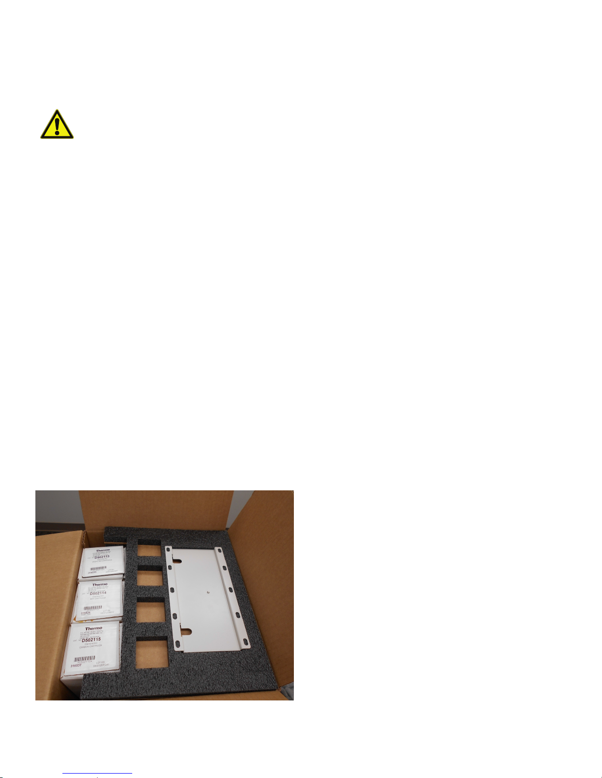
Examination on Receipt
1. Ensure all components for complete system were
ordered and received. This should include:
• Pretreatment system - 50157886
•1 μm Prefilter - D502113
• MPS Cartridge - D502114
• Carbon Cartridge - D502115
• Wall bracket (if wall mounting)
• TU494X4 6 ft (1.8 m) of ¼ OD tubing
• Feed-water Connection kit - 25.0071
2. Carefully unpack system and inspect system for damage.
Note: If the packaging show signs of damage, inspect the
system for damage.
Complaints
If there has been any damage occurred to the goods during
transportation:
• Immediately contact your delivery transport agency.
• Save the complete packaging, including the cardboard
box, for a possible inspection of them and/or return
shipment of the system.
Packaging for Return
Shipment
If possible, use the original box and packaging material. When
these are no longer available, then:
• Protect the system from shock by packing it in bubble
wrap and/or packaging foam and a strong cardboard
box.
Note: The time limit for claims is 6 days from the time of
receipt of the goods. The right to claim for damages ceases
when this time has elapsed.
Note:
• Only a trained person should take the system out of
operation.
• Prior to sending back an operated device, empty the
water, dry the system and take out the cartridges.
Figure 1. Unpacking
Pretreatment system Transport and Packaging | 3
• Pack the cartridges into a bubble wrap and/or packaging
foam and put it into the package of the Pretreatment
system.
Page 8

Intended Use of the Device
Outlet Inlet
The Thermo Scientific Barnstead Pretreatment system is
laboratory systems used for the treatment of water.
The Thermo Scientific Barnstead Water systems are designed
to be installed and used in the following application areas:
• Laboratories for cell biological and biotechnological work
with the safety levels L1, L2 and L3.
• Medical and microbiological laboratories according to
DIN EN 12128.
• Laboratories in the central area of clinics and hospitals.
The system must not be operated outside of the
specifications as described in the operating manual. In
particular, the system should not be used for production of
drinking water and drugs manufacturing. The system must
not be used as a medical device and outside of laboratories.
Note: Pretreatment system will operate with all Smart2Pure
and Pacific series water purification systems.
Figure 2. Front view of Pretreatment system
4 | Intended Use of the Device Pretreatment system
Page 9

Technical Specifications
Note: Check at regular intervals the quality of your feed-water.
Feed-water requirements
Source Potable tap water
Silt density index (SDI) <5
Turbidity <1 NTU
Conductivity (reference
temperature +25°C)
Chlorine Max. 3 ppm
Iron content Max. 0.5 ppm
pH range 4 - 11
Temperature +2°C - +35°C
Pressure
Feed-water supply ¾” NPT (adapts to ¼” NPT male or female)
Tubing Connections
Inlet Tubing Tube ¼” outer diameter
Outlet Tubing Tube ¼” outer diameter
1500 μS/cm (670 Ω·cm)
2 - 6.9 bar / 29 - 100 PSI (at a pressure >6.9 bar / 100 PSI a pressure reducer must
be installed upstream of the system.
Accessibility to Pretreatment system
Space to the Left & Right of Unit 15 cm / 6 inch
Space to the Front of the Unit 30 cm / 12 inch
Pretreatment system Technical Specifications | 5
Page 10

Figure 3. Dimensions of Pretreatment system
Dimensions and weight of Pretreatment system
Height / Height with Wall Bracket 15.58 inch / 15.17 inch
Width 11 inch
Depth / Depth with Wall Bracket 7.00 inch / 7.38 inch
Dry Weight 24.5 lbs (11.1 kg)
Wet Weight (during operation) 29 lbs (13.2 kg)
6 | Technical Specifications Pretreatment system
Page 11

The Installation Area
Note: The operator is obliged to ensure, that the installation of
the pretreatment system and its operation are carried out in
compliance with all national and international guidelines,
applicable and valid for the place of installation.
Note: If necessary, measures to protect the water have to be
taken by installing appropriate components.
Take the following criteria into consideration when selecting
the installation area:
• Feed-water pressure (potable tap water) not be less than
2 bar (29 PSI) and not greater than 6.9 bar (100 PSI).
• There must be a feed-water shut off valve installed ahead
of the Smart2Pure Pro system.
CAUTION: The feed-water pressure to
Pretreatment system must not be allowed to go
above 6.9 bar. Install an additional pressure
reducer when the feed-water pressure is higher.
• You must protect your system from frost. The
temperature at the installation area must be between
+2°C and +40°C.
• The surface on which the system is installed must be
level and stable. It should not exceed a maximum of 2%
deviation from evenness is recommended.
• A smooth wall is required when the system is to be wall
mounted. The bench or wall surface must have an
adequate load-carrying capacity (check the maximum
capacity of load the wall can sustain and the stability of
the wall). The dry and wet weight of the system is given
under section Technical Specifications.
• A low pressure check valve is recommended in the
feed-water line to prevent back flow of feed-water from
the water system. Refer to local building codes.
• Easy access for operation and control of the system.
Pretreatment system The Installation Area | 7
Page 12

Installation
Screw Mounting Holes
Screw Mounting Holes
Wall Bracket Slots
#8-32 UNC
(For Locking Screw)
Mounting Pins
(For Locking Screw)
#8-32 UNC
1. Requirements for installation:
• Screws and fasteners for wall bracket (if wall
mounting pretreatment)
• Tap water supply with shut off valve and ¾” NPT
male adapter
2. Locate Pretreatment system within 6 feet of Water
Purification system.
Wall Mounting Instructions
for Pretreatment System
Note: Before you begin mounting the system on the wall, you
must check that the strength of the wall to ensure it is suitable
for supporting the system (refer to the table “Dimensions and
weight of Pretreatment system” in the section Technical
Specifications).
Note: The system does not include screws and fasteners for
mounting, and requires minimum 4 fasteners (2 on top, 2 on
bottom).
3. Place Pretreatment system onto bracket by sliding the
mounting pins into the wall bracket slots (refer Figure 5).
4. Lock Pretreatment system into place by opening front
door and locating the locking screw hole. Fasten #8-32
locking screw from Pretreatment system to the wall
bracket (refer Figure 5).
The countertop base can be removed before wall mounting.
To remove the coutertop base, remove the 4 screws from the
bottom of unit.
1. Locate the wall bracket. Hold the wall bracket at the
desired position on the wall and check for levelness.
Mark four boreholes for fixing the wall bracket.
Figure 4. Wall mount bracket
2. Drill holes for fasteners, or drill screws directly into
backing board and attach wall bracket securely to the
wall.
Figure 5. Locking wall mount
Connections of the
Pretreatment System
Following connections are required for pretreatment system
to work:
1. 1 micro Prefilter cartridge quick disconnects
2. MPS anti-scalent cartridge quick disconnects
3. Extruded carbon filter quick disconnects
4. Outlet connector for outer diameter ¼” tube
5. Inlet connector for outer diameter ¼” tube
Note: If you remove any of the cartridges, water flow will stop.
In order to operate, all five connections above must be made,
and feed-water must be turned ON.
Tubing Installation:
Note: Use tube cutter to ensure ends of tubing are flat and
free of burrs (prickles).
8 | Installation Pretreatment system
Page 13

1. Mark from end of tube the length of insertion (1.75 cm /
Typical Fitting
Tubing
Collect
1.75 cm (11/16”)
Thumb Pad
Male Adapter
Dirt Screen
¾” Union Nut
Outer Diameter
¼” Tube
Fitting
11/16 inch)
2. Wet the tube end and insert the tube straight into the
fitting until it bottoms out on the interior shoulder and the
insertion mark is no longer visible. ()fa;sdujfa;oisd
Figure 6. Inserting tube into fittings
3. Install the MPS cartridge (D502114) by inserting into the
upper middle and lower middle quick disconnects. Push
firmly into place.
4. Install the Carbon filter (D502115) by inserting into the
upper left and lower left quick disconnects. Push firmly
into place.
Quick Disconnect Fittings:
These fittings are found on the Prefilter, MPS and Carbon
cartridges. To insert the cartridges:
1. Press on metal thumb pad on unit to ensure fitting is
open
1. Insert the male adapter into fitting and release your
thumb. Push the connector until your hear a click. Gently
pull the cartridge to ensure the connection is secure.
2. To remove cartridges, press on metal thumb pad to
release fitting and pull cartridge out.
Figure 8. Cartridge installation
Inlet / Outlet Connections:
1. Outlet Connection: Connect ¼” outer diameter tubing
to outlet connector on left side of Pretreatment system.
Then connect to the water purification system (i.e.
Smart2Pure Pro) as shown in the Typical Installation
section.
2. Inlet Connection: Connect ¼” outer diameter tubing to
the inlet connector on right side of the Pretreatment
system.
3. Feed-Water Connection: Using Feed-water fitting kit
from Smart2Pure Pro installation kit, connect inlet tubing
to the ¾” NPT feed-water connection.
4.
Figure 7. Quick disconnect fittings
Cartridge/Filter Installation:
1. Open the Front Door.
2. Install the Prefilter (D502113) by inserting into the upper
right and lower right quick disconnects. Push firmly into
place.
Pretreatment system Installation | 9
Figure 9. Feed-water fitting
Page 14

Typical Installation
Figure 10. Bench setup
Corrective measures
• All tubing and cartridges must be checked for their
correct position on the system and that no leakage or
blockage after opening the feed-water supply.
• To avoid tripping, ensure that the tubing does not lay over
the floor.
10 | Typical Installation Pretreatment system
Page 15

Flow Chart
Note: The following flow chart describes the Pretreatment system water flow path.
F1: Prefilter PS1: Prefilter Inlet Gauge
F2: MPS Cartridge PS2: Prefilter Outlet Gauge
F3: Carbon Filter PS3: Carbon Outlet Gauge
F4: FLX31 Pressure Gauge Filter, 25 μm V1: Pressure Regulator
Pretreatment system Flow Chart | 11
Page 16

How the Pretreatment System
Functions
When the system is in operation, tap water with a maximum
pressure of 6.9 bar flows into the system through the
feed-water Inlet connection on the bottom of the right side
panel.
The feed-water pressure is regulated to 30 psi via an internal
pressure regulator. This regulated pressure can be seen on
the Prefilter Inlet gauge.
The water then flows (upward) through the 1 μm Prefilter. The
Prefilter is used to remove particulates from your feed-water
which can damage/plug an RO Membrane downstream from
the system. A Prefilter Outlet pressure gauge shows the
pressure drop across the Prefilter by comparing the Prefilter
Inlet and Prefilter Outlet gauge. A pressure drop of > 10 psi
indicates a plugged Prefilter (which can reduce flow through
the Pretreatment system) and replacement is necessary.
Next the water flows into the MPS Anti-Scalent cartridge. The
MPS cartridge contains a slow dissolving anti-scalent material
which is designed to prevent hard water scale buildup on
down stream RO Membranes. Replace this cartridge when
the anti-scalent material is half dissolved.
After the MPS cartridge, the water flows into the Extruded
Carbon cartridge. The carbon cartridge removes chlorine
from your feed-water, which can damage RO Membranes.
Replace the carbon cartridge every 6 months. The Carbon
Outlet pressure gauge displays the pressure after the carbon
cartridge. Compare the Carbon Outlet gauge to the Prefilter
Outlet gauge to determine the pressure drop across the
carbon cartridge. Pressure drops of > 15 psi indicates the
carbon cartridge is blocked and needs replacement.
The water exits the Pretreatment system via the Outlet
connector on the bottom of the left side panel. Use a ¼” outer
diameter tube to connect to an RO system, such as the
Thermo Scientific Barnstead Smart2Pure or Pacific Series
water systems.
12 | How the Pretreatment System Functions Pretreatment system
Page 17

Initial start up
Putting the system into
operation
CAUTION: Check that all connections have been
made as described in the Installation section.
• Verify if all connections are secure and correct.
• Turn the feed-water ON. Verify no leaks are present in the
tubing, connectors, cartridges, etc. Turn the water
purification system (i.e. Smart2Pure Pro) downstream of
the Pretreatment system ON. Check for leaks once the
downstream water purification system starts production.
• Verify that all pressure gauges are showing pressure
readings.
• If no leaks or blockages are found, close the
Pretreatment system’s front door and allow operation to
continue.
Operating Elements
1. Prefilter Inlet
• Indicates water pressure after the regulator, before
entering the Prefilter
2. Prefilter Outlet
• Indicates water pressure after the Prefilter
3. Carbon Filter Outlet
• Indicates water pressure after the carbon filter
Figure 11. Pretreatment system gauge
Pretreatment system Initial start up | 13
Page 18

Maintenance
Regular servicing of the system ensures that the quality of the
treated water will remain constant. To ensure that your
system is serviced properly we recommend that you obtain a
maintenance contract with Thermo Fisher Scientific or factory
authorized service provider. You can then be certain that your
system will have a high degree of operational reliability and
dependability.
To ensure that your system functions without any errors it
must be checked, maintained and serviced at regular
intervals, as described in these operating instructions. The
operating instructions must therefore be kept in an easily
accessible location for anyone who is using or servicing the
system.
Material
Prefilter F1 D502113 6 months
MPS Cartridge F2 D502114 6 months Or when material is half dissolved
Carbon Filter F3 D502115 6 months
Flow
chart no.
Item No. Interval Other problems
Maintenance Intervals
Wear parts must be replaced in accordance with the following
table. The intervals have been established for the user and
depend on the actual, exact water quality and the volume of
water that is used daily.
Or when pressure drop exceeds 10 psi as indicated
by difference of Prefilter Inlet and Prefilter Outlet
gauges
Or when pressure drop exceeds 15 psi as indicated
by difference of Prefilter Outlet and Carbon Outlet
gauges
Note: The lifetime of the wear parts is a direct function of the quality of the feed-water and the daily volume of water that is
used.
14 | Maintenance Pretreatment system
Page 19

Waste Disposal
Note: Before returning your Thermo Scientific Barnstead
Pretreatment systems for waste disposal, contact your local
waste disposal company for proper disposal of the system
and its components. Only specially trained personal can take
the system out of operation and dispose it properly.
When the packaging is no longer needed it can be disposed
of as household waste. Systems are in conformity with EEC
Guideline 2011/65/EC.
The system is not to be thrown away as household waste but
must be properly disposed of. It can be returned to the
manufacturer for safe disposal according to EEC Guideline
2011/65/EC. We therefore request our customers in
Germany and other member States in the European
Economic Area to contact our local service center or our
headquarters.
weee.recycle@thermofisher.com
WEEE-Reg.-no.: DE 12471402
In countries outside of the European Economic Area, contact
your local authorities or waste disposal company.
Pretreatment system Waste Disposal | 15
Page 20

Troubleshooting
Note: Contact the service department if you cannot rectify these error.
Problem Cause Solution
Low Flow out of system
No Flow out of system No feed-water flow
Leakage in the system
Gauges not working
Plugged cartridge(s)
Low feed-water pressure
Tubing connector, Cartridge or
tubing
Faulty gauge
Blocked cartridge
No feed-water
Check Pressure gauges to determine if Prefilter or
Carbon cartridge is plugged.
Ensure feed-water is at least 2 bar
Verify feed-water is on, check for pressure on
Prefilter Inlet Gauge
Verify tubing is properly connected.
Verify cartridges are installed properly and are not
cracked.
Replace broken tubing or connectors. Call
Service
Replace faulty gauge
Try bypassing cartridges using 3/8" tubing with
CUX9 tubing connectors installed to check gauge
Turn on feed-water, or remove blockage
16 | Troubleshooting Pretreatment system
Page 21

Replacement Parts
Note: The use of spare parts, accessories or wear parts from other manufacturers will nullify the warranty for this unit.
Figure 12. Replacement part list for Pretreatment system
Drawing
ID
3 Feet 321191
4 Pressure Gauge MEX196
5 Pressure Regulator 02280
6 Inlet Connector PMX206
7 Outlet Connector PMX206
8 TEE Union PMX222
9 Elbow Union 212-00001
10 Elbow Stem PMX235
11 Male Connector 212-00002
12 Female Connector PMX236
13 Quick Disconnect Coupling 212-00003
14 25 Micron Tube Filter FLX31
Part
Part
Number
Drawing
ID
15 Wall Bracket 700-00006
Not shown:
• TU494X4 6 feet (1.8 meters) of ¼ OD tubing)
• 25.0071 Feed Water Connection kit
Replacement:
Consumables
Consumable Item No.
Prefilter Cartridge D502113
MPS Cartridge D502114
Carbon Cartridge D502115
Part
Part
Number
Pretreatment system Replacement Parts | 17
Page 22

Maintenance Record
Customer address:
Location:
System type:
Serial no.:
Manufacturing Year:
Date
Prefilter Replaced?
Y/N
MPS Replaced?
Y/N
Carbon Replaced?
Y/N
The following points must be observed in order to ensure the quality of the system.
• 1x/Weekly, enter measured values.
18 | Maintenance Record Pretreatment system
Page 23

WEEE Compliance
Great Britain
Deutschland
Italia
France
España
WEEE Compliance. This product is required to comply with the European Union’s Waste Electrical &
Electronic Equipment (WEEE) Directive 2012/19/EU. It is marked with the following symbol. Thermo
Fisher Scientific has contracted with one or more recycling/disposal companies in each EU Member
State, and this product should be disposed of or recycled through them. Further information on our
compliance with these Directives, the recyclers in your country, and information on Thermo Scientific
products which may assist the detection of substances subject to the RoHS Directive are available at
www.thermofisher.com under Services & Support.
WEEE Konformittät. Dieses Produkt muss die EU Waste Electrical & Electronic Equipment (WEEE)
Richtlinie 2012/19/EU erfüllen. Das Produkt ist durch folgendes Symbol gekennzeichnet. Thermo
Fisher Scientific hat Vereinbarungen getroffen mit Verwertungs-/Entsorgungsanlagen in allen EUMitgliederstaaten und dieses Produkt muss durch diese Firmen widerverwetet oder entsorgt werden.
Mehr Informationen über die Einhaltung dieser Anweisungen durch Thermo Scientific, dieVerwerter
und Hinweise die Ihnen nützlich sein können, die Thermo Fisher Scientific Produkte zu identizfizieren,
die unter diese RoHS. Anweisungfallen, finden Sie unter www.thermofisher.com unter Services &
Support.
Conformità WEEE. Questo prodotto deve rispondere alla direttiva dell’ Unione Europea 2012/19/EU
in merito ai Rifiuti degli Apparecchi Elettrici ed Elettronici (WEEE). È marcato col seguente simbolo.
Thermo Fischer Scientific ha stipulato contratti con una o diverse società di riciclaggio/smaltimento in
ognuno degli Stati Membri Europei. Questo prodotto verrà smaltito o riciclato tramite queste
medesime. Ulteriori informazioni sulla conformità di Thermo Fisher Scientific con queste Direttive,
l’elenco delle ditte di riciclaggio nel Vostro paese e informazioni sui prodotti Thermo Scientific che
possono essere utili alla rilevazione di sostanze soggette alla Direttiva RoHS sono disponibili sul sito
www.thermofisher.com in Servizi e Supporto.
Conformité WEEE. Ce produit doit être conforme à la directive euro-péenne (2012/19/EU) des
Déchets d’Equipements Electriques et Electroniques (DEEE). Il est marqué par le symbole suivant.
Thermo Fisher Scientific s’est associé avec une ou plusieurs compagnies de recyclage dans chaque
état membre de l’union européenne et ce produit devraitêtre collecté ou recyclé par celles-ci.
Davantage d’informations sur laconformité de Thermo Fisher Scientific à ces directives, les recycleurs
dans votre pays et les informations sur les produits Thermo Fisher Scientific qui peuvent aider le
détection des substances sujettes à la directive RoHS sont disponibles sur www.thermofisher.com
sous Services et Assistance.
Cumplimiento de la directiva RAEE. Este producto está obligado a cumplir con la Directiva de la
Unión Europea sobre residuos de aparatos eléctricos y electrónicos (RAEE) 2012/19/EU. Está
marcado con el siguiente símbolo. Thermo Fisher Scientific ha contratado a una o varias empresas de
reciclado/disposición de residuos en cada estado miembro de la UE, y este producto debe reciclarse
o desecharse a través de dichas empresas. Para obtener más información sobre nuestro
cumplimiento con estas directivas, las empresas de reciclaje de su país, así como información sobre
los productos Thermo Scientific que pueden ayudarle a detectar sustancias sujetas a la directiva
RoHS, visite www.thermofisher.com/WEEERoHS en la sección Servicios y Asistencia.
Page 24

IF YOU NEED ASSISTANCE:
Thermo Fisher Scientific products are backed by a global technical support team ready to support your applications. We offer
cold storage accessories, including remote alarms, temperature recorders, and validation services.
Visit
www.thermofisher.com or call:
Countries Sales Services
North America +1 866 984 3766 (800) 438-4851
India 1800 22 8374, +91 22 6716 2200 +91 22 6716 2200
China +800 810 5118, +400 650 5118 +8621 68654588
Japan +81 3 5826 1616 +81 3 3816 3355
Australia +61 39757 4300 1 300 735 292
Austria +43 1 801 40 0 +43 1 801 40 0
Belgium +32 53 73 42 41 +32 2 482 30 30
France +33 2 2803 2180 +33 2 2803 2180
Germany 0800 1 536 376, +49 6184 90 6000 0800 1 536 376
Italy +32 02 95059 552 +39 02 95059 552, 432 254 375
Netherlands +31 76 579 55 55 +31 76 571 4440
Nordic/Baltic/CIS +358 9 329 10200 +358 9 329 100
Russia +7 812 703 4215 +7 812 703 4215
Spain/Portugal +34 93 223 09 18 +34 93 223 09 18
Switzerland +41 44 454 12 22 +41 44 454 12 12
UK/Ireland +44 870 609 9203 +44 870 609 9203
New Zealand +64 9 980 6700 +64 9 980 6700
Other Asian Countries +852 2885 4613 +852 2885 4613
Countries not listed +49 6184 90 6000 +49 6184 90 6000
Thermo Fisher Scientific Inc.
275 Aiken Road
Asheville, NC 28804
United States
Find out more at thermofisher.com
© 2018 Thermo Fisher Scientific Inc. All rights reserved. All trademarks are the property of
Thermo Fisher Scientific and its subsidiaries unless otherwise specified. 50157886 1018
 Loading...