

Thermo Scientific Barnstead Nanopure TOC - UV, Barnstead Nanopure TOC - UV 2115 Series, Barnstead Nanopure TOC - UV 2117 Series, D11951, D12421 Operation Manual

Barnstead Nanopure
TOC - UV
ultrapure water system
Operation Manual
Series 2115 and 2117
™
LT2115X1 • 11/23/09
Model No. Voltage
D11951 100V - 240V
D12421 100V - 240V

Table of Contents
Safety Information ........................................................................................................................................................................................................3
lert Signals ........................................................................................................................................................................................................3
A
arnings..............................................................................................................................................................................................................3
W
Introduction....................................................................................................................................................................................................................5
eneral Usage ....................................................................................................................................................................................................5
G
General Specifications ..................................................................................................................................................................................................6
nvironmental Conditions....................................................................................................................................................................................7
E
eclaration of Conformity....................................................................................................................................................................................7
D
Unpacking......................................................................................................................................................................................................................8
nstallation......................................................................................................................................................................................................................9
I
Choosing a Site ..................................................................................................................................................................................................9
V Lamp Installation ........................................................................................................................................................................................10
U
ther Accessories ............................................................................................................................................................................................10
O
Bench Mounting ................................................................................................................................................................................................11
all Mounting ....................................................................................................................................................................................................11
W
Installing the Control Panel in a Remote Location ............................................................................................................................................12
ater Connections ............................................................................................................................................................................................13
W
ubing Installation..............................................................................................................................................................................................14
T
Electrical Connections ......................................................................................................................................................................................14
ontrols ......................................................................................................................................................................................................................15
C
ain Power Switch............................................................................................................................................................................................15
M
Control Panel ....................................................................................................................................................................................................15
Switches ............................................................................................................................................................................................................16
nitial Operation ..........................................................................................................................................................................................................17
I
Cartridge Pack Installation ................................................................................................................................................................................17
Initial Rinse ........................................................................................................................................................................................................18
System Cleaning Procedure..............................................................................................................................................................................19
Normal Operation ........................................................................................................................................................................................................21
Dispensing Water ..............................................................................................................................................................................................22
Automatic Dispensing........................................................................................................................................................................................22
User Settings ..............................................................................................................................................................................................................23
Adjusting Display Brightness ............................................................................................................................................................................23
Setting the Displayed Language ......................................................................................................................................................................23
Setting the Date and Time ................................................................................................................................................................................24
Setting the Cell Constant ..................................................................................................................................................................................25
Use of Standby Mode........................................................................................................................................................................................26
Selecting the Set Point ......................................................................................................................................................................................26
Resetting the Cleaning Timer............................................................................................................................................................................27
Resetting the UV Timer ....................................................................................................................................................................................28
Resetting the TOC Lamp Timer ........................................................................................................................................................................28
Using the TOC Analyzer....................................................................................................................................................................................29
Setting Volumetric Dispensing ..........................................................................................................................................................................30
Setting Timed Dispensing..................................................................................................................................................................................30
Performing a System Flush ..............................................................................................................................................................................31
Changing Purity Units........................................................................................................................................................................................31
Temperature Compensation ..............................................................................................................................................................................31
Auto Standby ....................................................................................................................................................................................................32
Unit Under Counter............................................................................................................................................................................................32
Accessories ................................................................................................................................................................................................................34
Feedwater Float or Pressure Switch ................................................................................................................................................................34
Dispense Overflow Cutoff Float ........................................................................................................................................................................35
Performing an Electronic Calibration Using the Optional N.I.S.T. Calibration Module ......................................................................................36
Manual Remote Dispenser and Accudispense Volumetric Remote Dispenser ................................................................................................37
Computer/Printer Setup ..............................................................................................................................................................................................38
Connecting Nanopure to Computer and Communicating Through the RS-232 Port Using Hyperterminal or Procomm ................................38
Connecting and Starting the Printer ..................................................................................................................................................................40
Printer Setup......................................................................................................................................................................................................41
Maintenance and Servicing ........................................................................................................................................................................................42
General Cleaning Instructions ..........................................................................................................................................................................42
Cell Cleaning ....................................................................................................................................................................................................42
System Cleaning ..............................................................................................................................................................................................43
System Depressurization ..................................................................................................................................................................................44
Cartridge Pack Replacement ............................................................................................................................................................................45
0.2 Micron Filter Replacement ..........................................................................................................................................................................46
UV Lamp Replacement ....................................................................................................................................................................................47
TOC Lamp Replacement ..................................................................................................................................................................................48
Fuse Replacement ............................................................................................................................................................................................48
Shutdown ..........................................................................................................................................................................................................49
Troubleshooting ..........................................................................................................................................................................................................50
Replacement Parts ......................................................................................................................................................................................................54
Flow Chart ..................................................................................................................................................................................................................56
Wiring Diagram............................................................................................................................................................................................................57
Ordering Procedures ..................................................................................................................................................................................................58
Two Year Limited Warranty..........................................................................................................................................................................................60
Alert Signals
Warning
Warnings alert you to a possibility of
personal injury.
Caution
Cautions alert you to a possibility of
damage to the equipment.
Note
Notes alert you to pertinent facts and
conditions.
Safety Information
Your Thermo Scientific Barnstead Nanopure TOC - UV
ultrapure water system has been designed with function,
reliability, and safety in mind. It is your responsibility to
install it in conformance with local electrical codes. This
manual contains important safety information. You must
carefully read and understand the contents of this manual
prior to the use of this equipment. For safe operation,
please pay attention to the alert signals throughout the
manual.
Water purification technology employs one or more of the
following: chemicals, electrical devices, mercury vapor
lamps, steam and heated vessels. Care should be taken
when installing, operating or servicing Barnstead products. The specific safety notes pertinent to this Barnstead
product are listed below.
Note
The UV lamp contains mercury. If broken or no longer needed, do not dispose of the UV lamp in the trash.
Recycle or dispose of the UV lamp as
hazardous waste.
Warnings
To avoid electrical shock, always:
1. Use a properly grounded electrical outlet of
correct voltage and current handling capacity.
2. Do not locate the Nanopure TOC - UV directly
over equipment that requires electrical service.
Routine maintenance of this unit may involve
water spillage and subsequent electrical shock
hazard if improperly located.
3. Replace fuses with those of the same type and
rating.
4. Disconnect from the power supply prior to maintenance and servicing.
To avoid personal injury:
1. Do not use in the presence of flammable or
combustible materials; fire or explosion may
result. This device contains components which
may ignite such materials.
2. This device is to be used with water feeds only.
Cleaning agents must be used in compliance
with instructions in this manual. Failure to comply with the above could result in explosion and
personal injury.
3

SAFETY INFORMATION
3. Avoid splashing cleaning solutions on clothing or
skin.
4. Ensure all piping connections are tight to avoid
chemical leakage.
5. Ensure adequate ventilation.
6. Carefully follow manufacturer’s safety instructions on labels of chemical containers and material safety data sheets.
7. Depressurize system prior to removing the
cartridge pack.
8. This unit is equipped with an ultraviolet lamp.
Ultraviolet radiation is harmful to the eyes and
skin. Do not attempt to observe the lamp
directly.
9. Refer servicing to qualified personnel.
10. A full cartridge pack may weigh about 20 lbs.
4

Introduction
Congratulations on your purchase of a Barnstead
Nanopure TOC - UV ultrapure water system. This water
purification system is designed to provide low TOC, high
resistivity, reagent grade water that exceeds ASTM Type
I, ISO 3696 and CLSI-CLRW Type I standards. It uses a
four-stage deionization process combined with a UV lamp
and a 0.2 micron filter to polish suitable feed water (distilled, deionized, or reverse osmosis) to produce low TOC
(<5 ppb) water with a resistivity of up to 18.2 megohmcm. Water resistivity is continuously monitored by a resistivity cell and displayed on a digital display. Actual system
TOC values, obtained by an integrated TOC analyzer, can
be concurrently displayed with the resistivity.
The electronics can be verified and calibrated utilizing a
N.I.S.T. Traceable Calibration module. See accessory
ordering information.
Please read the instructions carefully to ensure that you
receive maximum benefit from the Nanopure UV. Also,
please fill out and return the enclosed warranty registration card as it will help us assure you of proper warranty
coverage.
General Usage
Do not use this product for anything other than its intended usage.
5

General Specifications
Dimensions and Clearance Requirements
Dimensions
13.5” W x 19.5” H x 17.0” D (34.3 x 49.5 x 43.2 cm)
Clearances
Sides - 9” (22.9 cm) minimum for servicing.
Above - 3” (7.6 cm) minimum for removal of the top cover.
Front - 4.75” (12.1 cm) minimum for opening the front door.
Feed Water Requirements
Types RO, DI, distilled.
TOC Less than 1.0 ppm.
Turbidity 1.0 N.T.U. maximum.
Pressure Range Gravity feed to 100 psig (7kg/cm2) maximum.
Temperature Range 4°C - 40°C (40-104°F)
TDS (CaCO3) < 70 ppm
Silica < 1 ppm
Silt < 5% SDI
Product Water
Water Quality
Resistivity > 18.2 mΩ-cm
TOC Less than 5 ppb
Bacteria < 0.01 CFU/mL
Flow Rate
Up to 2 lpm maximum at minimum inlet feed water pressure 10 PSIG with a new final filter.
Volumetric Dispense
Accuracy: ± 5%
Repeatability: ± 3%
TOC Analyzer
Range 1 to 250 ppb
Accuracy ±1 ppb or ±15% (whichever is greater)
Cycle Time < 3.5 minutes
Water Consumption < 15 ml per cycle
Min. Water Resistivity > 10 MΩ for specified accuracy
6

GENERAL SPECIFICATIONS
Electrical Requirements
The Nanopure TOC - UV is equipped with 2 power cords to be plugged into an electrical outlet of the appropriate voltage.
U.K. customers use cord, CRX100 and fuses for 240V installation.
Model D11951, D12421 100-240 VAC, 100 watts, 47-63 Hz, 1 phase
Environmental Conditions
Operating: 4°C - 40°C; 20% to 80% relative humidity, non-condensing. Installation
Category II (over-voltage) in accordance with IEC 664. Pollution Degree 2 in
accordance with IEC 664.
Altitude limit: 3,500 meters.
Storage: -25°C to 65°C; 10% to 85% relative humidity.
Declaration of Conformity
We hereby declare under our sole responsibility that this product conforms with the technical requirements of
the following standards:
EMC: EN 61000-3-2 Limits for Harmonic Current Emissions
EN 61000-3-3 Limits for Voltage Fluctuations and Flicker
EN 61326-1 Electrical Equipment for Measurement, Control, and Laboratory Use; Part I:
General Requirements
Safety: EN 61010-1 Safety Requirements for Electrical Equipment for Measurement, Control and
Laboratory Use; Part I: General Requirements
per the provisions of the Electromagnetic Compatibility Directive 89/336/EEC, as amended by 92/31/EEC and
93/68/EEC, and per the provisions of the Low Voltage Directive 73/23/EEC, as amended by 93/68/EEC.
The authorized representative located within the European Community is:
Thermo Fisher Scientific
419 Sutton Road
Southend On Sea
Essex SS2 5PH
United Kingdom
Copies of the Declaration of Conformity are available upon request.
7

Unpacking
1. Remove the unit from its shipping container.
Remove all contents carefully. Ensure that the
UV lamp, feed and drain tubing, cleaning cartridge, wall bracket, accessory parts bag and
power cords (see list below) are removed
from the packaging materials before discarding. Put the Nanopure TOC - UV on a bench.
UV Lamp LMX13
Cleaning Cartridge CMX25
Wall Bracket (Unit) BC1190X12
Wall Bracket (Remote Display) BC1190X10
Accessory Parts Bag Includes:
Feed Water Tube, 3/8” O.D. TU1119X7
Drain Tube, 14” O.D. TU1190X12
Display Cable WHX20
Blank Display DL1190X18
Plug Adapter CEX42
Power Cords
Also required for installation:
* Customer Supplied Fasteners to mount unit and remote
display.
8
Installation
Caution
Wall composition, condition and
construction as well as fastener type
must be considered when mounting
this unit. The mounting surface and
fasteners selected must be capable of
supporting a minimum of 150 lbs.(68
kg). Inadequate support and/or fasteners may result in damage to mounting
surface and/or equipment. If you are
unsure of mounting surface
composition, condition and construction or correct fasteners, consult your
building maintenance group or
contractor.
Warning
Do not locate the Nanopure TOC - UV
directly over equipment that requires
electrical service. Routine maintenance of this unit may involve water
spillage and subsequent electrical
shock hazard if improperly located.
Choosing a Site
The Nanopure TOC - UV features a removable control
panel display which allows the system to be mounted
almost anywhere within the laboratory. Use the wall
bracket for wall mounted systems as a template to drill
mounting holes. (The Nanopure TOC - UV does not
include screws and fasteners for mounting.) Please refer
to the “General Specifications” section for clearance
requirements.
Do not use in the presence of
flammable materials; fire or explosion
may result. This device contains
components which may ignite such
materials.
NOTE
********************
The outlet of a gravity feed storage
reservoir must be above or at the
same level as the inlet of the
Nanopure TOC - UV.
************************
9
INSTALLATION
Note
The UV lamp contains mercury. If
broken or no longer needed, do not
dispose of the UV lamp in the trash.
Recycle or dispose of the UV lamp as
hazardous waste.
Caution
DO NOT TOUCH THE GLASS PORTION OF THE LAMP! It is recommended that lint-free gloves be worn
when handling the lamp. The glass
portion must be free of fingerprints,
perspiration, etc. Even a light coating
of perspiration will reduce the effectiveness of the lamp. If the glass portion of the lamp is touched, clean it
with a damp, lint-free cloth: use
isopropyl alcohol as required.
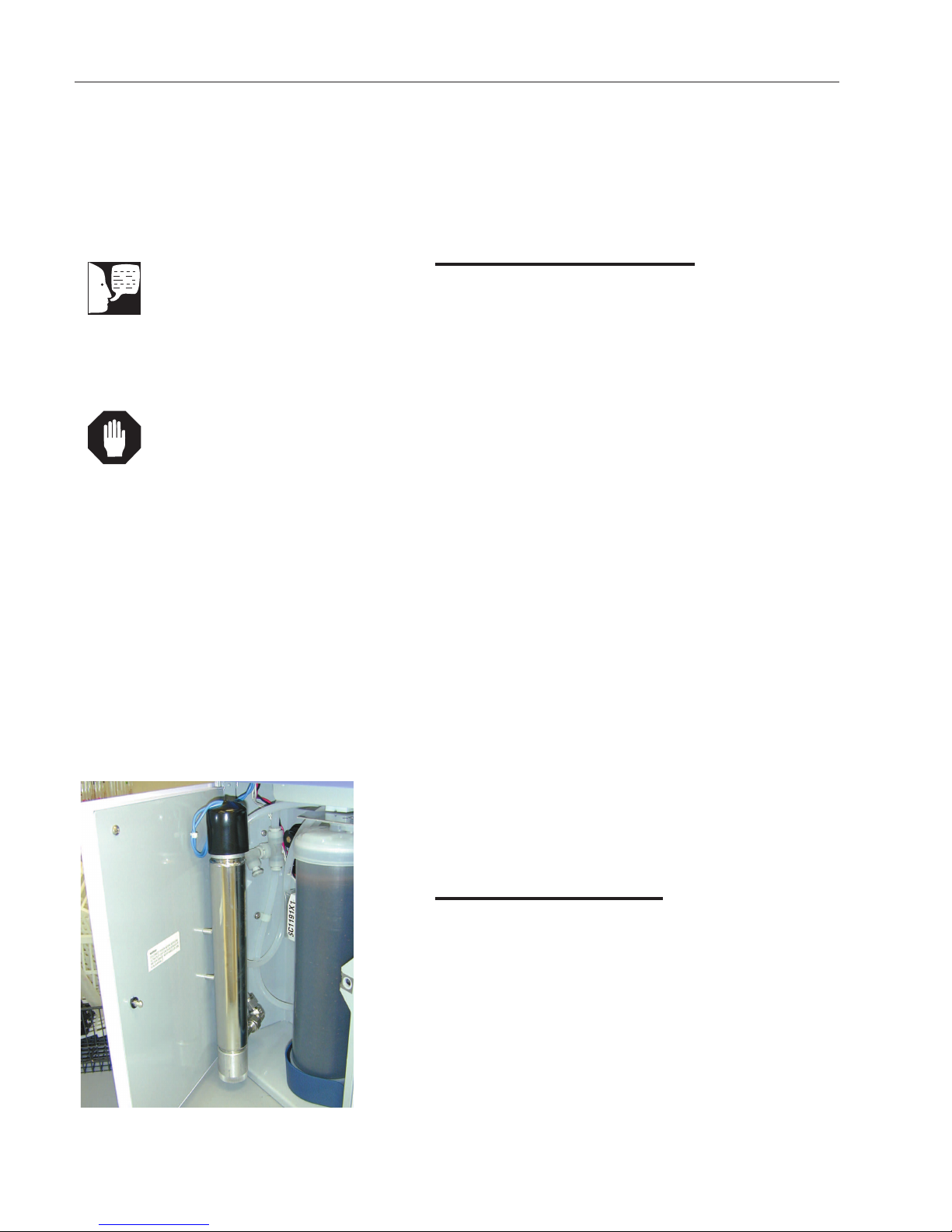
UV Lamp Installation
Locate the UV chamber inside the left door of the
Nanopure TOC - UV. Install the UV Lamp as follows:
1. Disconnect the power cord from the unit.
2. Access the left side of the unit by unlatching the
screw securing the door with a flathead screwdriver. Open the door. The UV lamp will be
installed vertically.
3. Remove the UV lamp from its packaging. DO
NOT TOUCH THE GLASS PORTION OF THE
LAMP! It is recommended that lint-free gloves
be worn when handling the lamp. The glass portion must be free of fingerprints, perspiration,
etc. Even a light coating of perspiration will
reduce the effectiveness of the lamp. If the glass
portion of the lamp is touched, clean it with a
damp, lint-free cloth: use isopropyl alcohol as
required.
4. Remove black cap by sliding off UV housing.
5. Insert the lamp halfway into the UV lamp chamber and plug it in, then fully insert the lamp into
the chamber.
Figure 1: UV Lamp Installation - Left side view
10
6. Make sure the UV lamp cable is tucked behind
the chamber before closing and relatching the
door.
Other Accessories
Optional accessories for this unit include a float switch,
low pressure switch, N.I.S.T. Traceable Calibration
Module, standard remote dispenser, Accudispense volumetric remote dispenser, dispense overflow cutoff float
and printer. If you purchased a float switch or low pressure switch, refer to page 31 of this manual. If you purchased a standard or Accudispense volumetric remote
dispenser, refer to their respective operator’s manuals for
installation instructions.
INSTALLATION
Caution
Wall composition, condition and construction, as well as fastener type,
must be considered when mounting
this unit. The mounting surface and
fasteners selected must be capable of
supporting a minimum of 150 lbs.(68
kg). Inadequate support and/or fasteners may result in damage to mounting
surface and/or equipment. If you are
unsure of mounting surface composition, condition and construction or correct fasteners, consult your building
maintenance group or contractor.
Note
Please refer to the “General
Specifications” section for clearance
requirements.
Warning
Do not locate the Nanopure TOC - UV
directly over equipment that requires
electrical service. Routine maintenance of this unit may involve water
spillage and subsequent electrical
shock hazard if improperly located.
NOTE
********************
The outlet of a gravity feed storage
reservoir must be above or at the
same level as the inlet of the
Nanopure TOC - UV.
Bench Mounting
1. Place the Nanopure TOC - UV on a bench top
that is accessible to pretreated water, electricity
and an atmospherically vented drain.
Wall Mounting
Install the Nanopure TOC - UV on a wall in a convenient
location that is accessible to water, an atmospherically
vented drain and electricity.
1. Locate the wall bracket packed separately from
the unit.
2. Using the wall bracket as a template, locate and
drill the mounting holes in the wall. A minimum of
four (customer-supplied) fasteners will be
required — two on the top and two on the bottom.
3. Attach the wall bracket to the wall using the cus-
tomer-supplied fasteners.
4. Remove the locking screws on each side of the
wall bracket.
5. Pull the two locking slides on each side of the
wall bracket out as far as they will go.
6. Hang the unit on the wall bracket by sliding the
mounting pins into the wall bracket slots.
7. Push the locking slides on each side of the wall
bracket in as far as they will go.
8. Replace the locking screws.
************************
11
INSTALLATION
Note
The removable control panel was not
designed to be repeatedly removed
from the unit, therefore, you may
experience difficulty when attempting
to remove it. It is therefore
recommended that the control panel
be permanently mounted in a remote
location or remain intact with the unit.
Caution
Repeated removal and replacement of
the control panel from the top cover
may eventually cause it to become
damaged.
Note
A bracket is available that will allow
you to mount the control panel on the
bench. If bench mounting is desired,
please order bracket AY1367X2.
Note
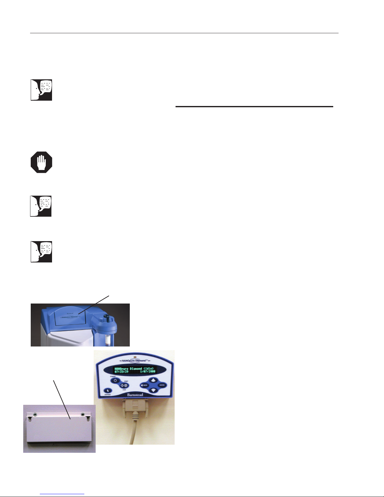
The blank protective cover on the rear
side panel display connector should
remain in place when the display is
not remotely located.
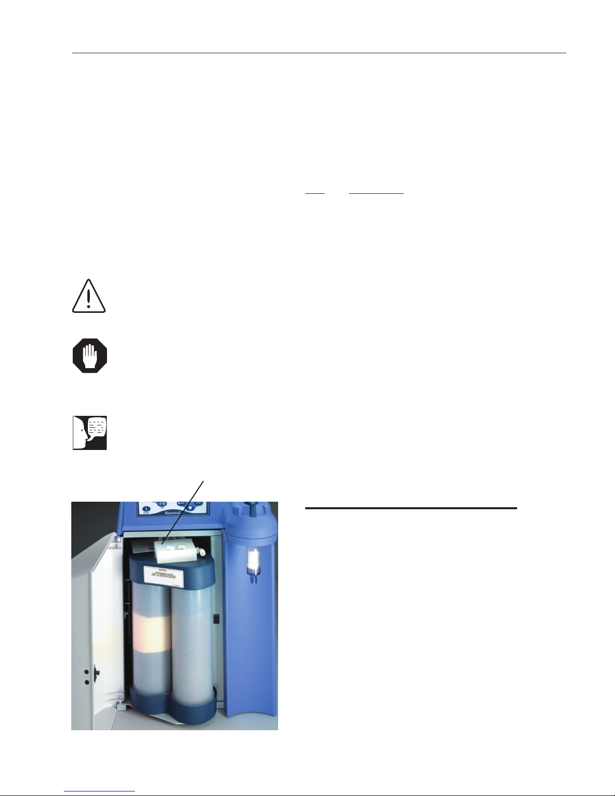
Blank panel
Installing the Control Panel in a
Remote Location
For your convenience, the control panel can be removed
from the unit and mounted at a convenient location within
10 ft. (3.1 m.) of the unit. To remove the control panel
from the unit:
1. Turn the unit OFF and disconnect it from the
power supply.
2. Slide the control panel upward about 1/4” (.64
cm) to 3/8” (.95 cm) - (just enough to clear connector on top cover), pull forward, and remove.
(The control panel fits tightly in the unit so it may
be difficult to remove.)
3. Replace the control panel with the blank panel
provided with the unit to protect the electrical
connector.
4. Using the wall bracket as a template, locate and
drill the mounting holes in the wall. A minimum
of two (customer-supplied) fasteners will be
required. Attach the wall bracket to the wall
using the customer-supplied fasteners.
Wall Mount
Bracket
Figure 2: Mounting the Control Panel
12
5. Locate the 25-pin connector on the back top
right of the unit. Remove the protective black
cover and store it for future use if the control
panel is returned to the top cover.
6. Locate the 10 ft. (3.1 m.) 25 pin M-F cable
included with the unit; attach the female end to
the 25 pin connector on the back top right of the
unit, and the other end to the connector on the
bottom of the control panel.
7. Tighten the cable screws on each end to secure
the cable to the unit and control panel.
8. The control panel may now be mounted on the
wall.
Caution
Do not connect feed water until directed to do so during “Initial Cleaning.”
Accudispense
control cable
Pump
Interlock
Remote 1
Remote 2
Feed
Water Inlet
Atmospheric
Drain
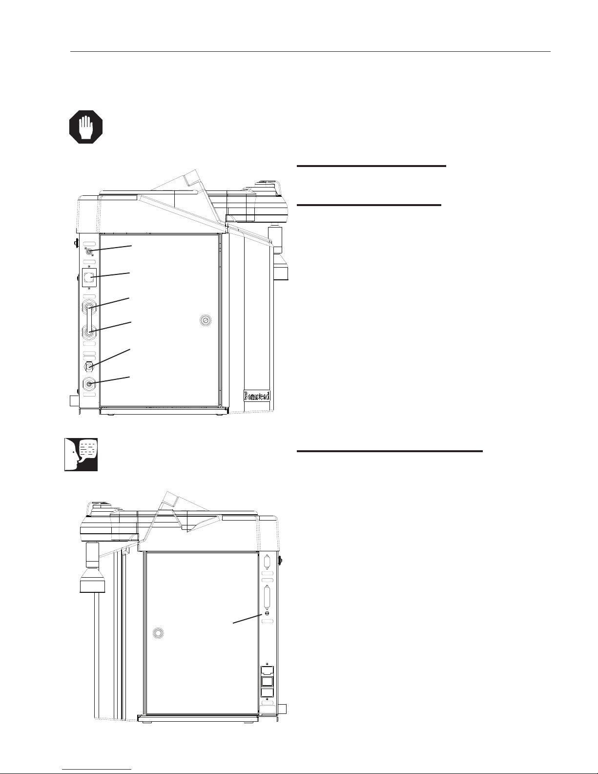
INSTALLATION
Water Connections
Feed Water Connection
1. Locate the length of 3/8” O.D. tubing provided
with the unit with a quick disconnect insert on
one end and a 3/8” (.95 cm) O.D. X 1/4” (.64
cm) NPT tubing adapter on the other.
2. Install the tubing adapter onto your incoming
water line. We recommend a customer supplied
shut off valve be installed in your feed water
line. Do not connect the feed water to your
Nanopure TOC - UV. You will connect the feedwater during the “Initial Cleaning” procedure
explained later in this manual. Note: The cartridge pack must be installed before connecting
water line.
Figure 3: Water Connections - Left side view
Note
To prevent leaking, push the tubing into
the atmospheric drain connection until it
bottoms out.
Overflow Float
Connection
3. If a pressure switch is to be used, see the
“Installing a Float or Pressure Switch” section
for more information.
Atmospheric Drain Connection
When the Nanopure TOC - UV flushes its membrane, the
water used is sent to drain through this connection. To
install:
1. Locate the drain water tubing. This is the 1/4”
(.64 cm) O.D. tubing that is approximately 6 ft.
(1.9 m.) long. The atmospheric drain fitting is
located on the lower left side of the Nanopure
TOC - UV.
2. Route the other end of the drain water tubing to
an atmospherically vented drain and make a
connection. Ensure there are no kinks in the
tubing and that it proceeds in a downward
plane. Proceed to “Initial Operation.”
Figure 4: Water Connections - Right side view
13
INSTALLATION
Fuse Holder
Power Switch
Power Cord
COLLET
TUBING
**
TYPICAL
FITTING
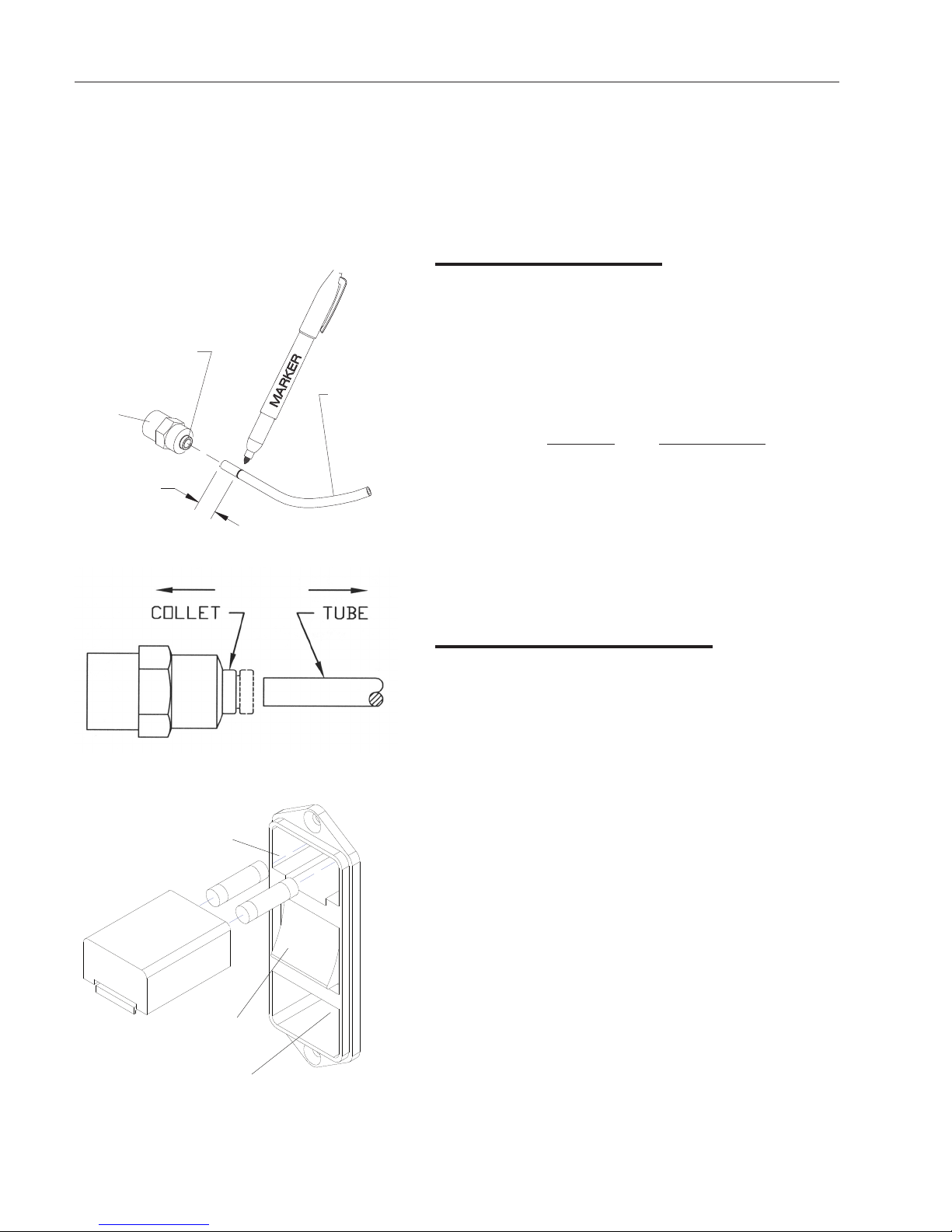
Figure 5: Tubing Adapter Installation
Tubing Installation
To make tubing connections:
1. Make sure the tubing is cut off reasonably
square and that no plastic burrs or ridges
are present.
2. *Mark from end of tube the length of insertion.
Tube size Insertion length
1/4 O.D. 1.75 cm (11/16”)
3/8 O.D. 1.9 cm (3/4”)
3. Wet the tube end with water and insert tube
straight into fitting until it bottoms out on interior
shoulder and insertion mark is no longer visible.
Figure 6: Tubing removal
4. To remove tubing, push collet toward fitting body
and pull on tubing. To reuse fitting, begin assembly
at step one.
Electrical Connections
The Nanopure comes with a 120 V power cord with (2) 1.6
amp fuses and 240 V power cords with (2) 0.63 amp fuses.
The Nanopure is not shipped with fuses installed in the fuse
draw of the power module. Before connecting the power
cord to the power module, install the proper fuses in the
fuse holder. Refer to the figure on the left.
Figure 7: Electrical Connections
14
Note
Barnstead
S
TANDBY
START
STOP
DISPENSE
NANOpure DIamondNANOpure DIamond
™
BACK
ENTER
The removable control panel was not
designed to be repeatedly removed
from the unit, therefore, you may
experience difficulty when attempting
to remove it. It is therefore recommended that the control panel be permanently mounted in a remote location
or remain intact with the unit.
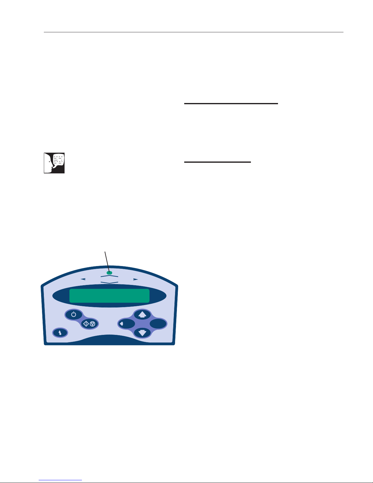
LED
Controls
Main Power Switch
The main power switch on the Nanopure TOC - UV is
located on the lower back right side of the unit (as you
face the front of the unit), directly above the power cord
receptacle.
Control Panel
The Nanopure TOC - UV is controlled through a panel
which incorporates switches to control its functions:
START/STOP, STANDBY, DISPENSE, DOWN, UP,
ENTER and BACK. This control panel utilizes a digital display to show system information and the purity of the
product water. The intensity (brightness) of the display
may be adjusted according to user preference. See
“Adjusting Display Brightness” in the “User Settings” section of this manual.
A single LED located on the top of the control panel will
illuminate to inform you of the system status as follows:
• LED is not illuminated: System is OFF or in
(Idle) mode.
Figure 8: Nanopure TOC - UV Control Panel
• Solid Green LED: System is recirculating and
operating normally.
• Blinking Green LED: System is in Standby
mode.
• Red LED: System is alerting user to an
operational error or maintenance issue.
The control panel can be removed from the unit and
remotely mounted. Please refer to “Installing the Control
Panel in a Remote Location” in the “Installation” section of
this manual for more information about how to remove the
control panel from the unit.
15

CONTROLS
Switches
When the main power switch (on the lower back right side
of the unit as you face the unit) is ON, the switches on
the control panel function as follows:
START/STOP allows you to alternate the unit between
the normal (recirculation) mode; when the display is
showing purity, and the (Idle) mode.
STANDBY allows you to put the unit into standby, recirculating water for 10 minutes/hour. The display will read
“Standby” during periods of inactivity and “Recirculating”
and the time remaining during the 10 minute recirculation.
Note
The unit MUST be in the normal recirculating mode (when the display is
showing purity) in order to dispense
water.
DISPENSE allows you automatically deliver water from
the unit. Please refer to”Automatic Dispensing” in the
“User Settings” section of this manual for information.
UP and DOWN arrows allow you to scroll between menu
options/items and values.
BACK allows you to return to the previous menu
option/item. Please note that use of the BACK switch
from a selection screen will return you to the previous
menu option/item while maintaining the selection’s value
upon entry.
ENTER allows you to activate a selected menu
option/item and also functions as “Yes” whenever an
option with a question mark appears.
DISPENSE KNOB when the unit is in the recirculation
mode, push to the right to deliver water continuously until
pushed back to the middle. Push to the left to deliver
water manually until button is released.
16
Initial Operation
Cartridge packs will come bagged with four manifold
connection caps.
Part Application
DIamond Kit Organic Free R/O & Distilled Feed
D50280 Ultra-Low Organics, Type 1 Water,
Reverse Osmosis or Distilled
Water Feed
DIamond Kit Organic Free Deionized Feed
Warning
Depressurize system prior to removing
cartridge pack.
Caution
Do not allow the Nanopure TOC - UV
to operate unless water is available to
the unit.
Note
Do not install the 0.2 micron filter and
bell assembly at this time.
Manifold
D50281 Ultra-Low Organics, Type 1 Water,
Deionized Water Feed
DIamond Kit Type 1 R/O & Distilled Feed
D50282 Low Organics, Type 1 Water,
Reverse Osmosis or Distilled
Water Feed
DIamond Kit Type 1 Deionized Feed
D50283 Low Organics, Type 1 Water, DI
DI Water Feed
Each cartridge pack includes one 0.2 micron absolute
final filter.
Cartridge Pack Installation
1. Open front (left side) door. Turn the cartridge
pack so the caps are facing you. Remove the
caps.
Figure 9: Cartridge Pack Installation
2. Verify that each of the four posts on the cartridge pack has an o-ring.
3. Lift unit manifold upwards, insert cartridge pack
and align the pack so that it mates with the unit
manifold.
4. Lower unit manifold until it is flush with the top
of the cartridge pack.
5. Hand tighten wing head screws securely.
6. Close door.
17

INITIAL OPERATION
Warning
Use a properly grounded electrical
outlet of correct voltage and current
handling capacity.
Initial Rinse
1. Attach the feed water line to the unit by snapping the quick disconnect coupling into the quick
disconnect body in the lower left back of the
unit.
2. Attach an atmospheric drain line [1/4” (.64 cm) ]
tubing by pushing into the quick connect fitting
on the lower left back of unit. See layout connection under the “Water Connections” section.
3. Check to ensure the dispense knob is in the
OFF (middle) position.
4. Select the appropriate power cord, remove and
install the two fuses into the fuse draw in the
power entry module. U.K. customers use cord
CRX100 and fuses for 240V installation.
Caution
Never dispense water without first
installing hose barb provided in
parts bag or final filter supplied with
cartridge pack.
5. Connect/attach to proper electrical outlet and
the unit.
6. Turn the unit on by turning the main power
switch to the “I” (ON) position.
7. The system greeting will display the type of unit
you own. This greeting is “UV TOC.”
8. The system electronics will initialize and check
its calibration. (All units have been factory calibrated.) If calibration is OK the display will show
“Calibration (passed).” The display will next read
“Self Test (in progress) Self Test. Passed.”
Finally, the display will read “10 (±0.2) MΩ-cm.”
This is a reading of the calibration reference
value. Finally the display will show “TOC
Initialization,” “TOC: (In Progress).” (Note: The
TOC initialization phase may take up to 45 seconds.)
9. From the (Idle) mode, when the display reads,
“Nanopure (Idle) xx:xx:xx xx/xx/xx,” press
ENTER to run an air purge.
18
10. Unit will display, “Air Purge?” Press ENTER.
 Loading...