

Page 1
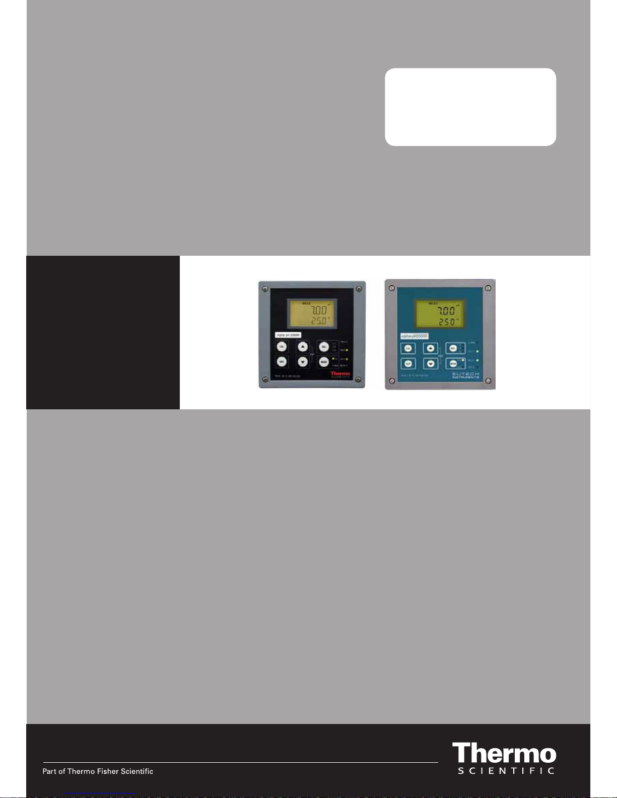
Alpha pH 2000
Processor/Transmitter
pH / ORP
Page 2

ROSS and the COIL trade dress are trademarks of Thermo Fisher Scientific Inc. U.S.
patent 6,793,787.
AQUAfast, Cahn, ionplus, KNIpHE, No Cal, ORION, perpHect, PerpHecT,
PerpHecTion, pHISA, pHuture, Pure Water, Sage, Sensing the Future, SensorLink,
ROSS, ROSS Ultra, Sure-Flow, Titrator PLUS and TURBO2 are registered
trademarks of Thermo Fisher.
1-888-pHAX-ION, A+, All in One, Aplus, AQUAsnap, AssuredAccuracy, AUTO-BAR,
AUTO-CAL, AUTO DISPENSER, Auto-ID, AUTO-LOG, AUTO-READ, AUTO-STIR,
Auto-Test, BOD AutoEZ, Cable-Free, CERTI-CAL, CISA, DataCOLLECT, DataPLUS,
digital LogR, DirectCal, DuraProbe, Environmental Product Authority, Extra
Easy/Extra Value, FAST QC, GAP, GLPcal, GLPcheck, GLPdoc, ISEasy, KAP,
LabConnect, LogR, Low Maintenance Triode, Minimum Stir Requirement, MSR,
NISS, One-Touch, One-Touch Calibration, One-Touch Measurement, Optimum
Results, Orion Star, Pentrode, pHuture MMS, pHuture Pentrode, pHuture Quatrode,
pHuture Triode, Quatrode, QuiKcheK, rf link, ROSS Resolution, SAOB, SMART
AVERAGING, Smart CheK, SMART STABILITY, Stacked, Star Navigator 21, Stat
Face, The Enhanced Lab, ThermaSense, Triode, TRIUMpH, Unbreakable pH,
Universal Access are trademarks of Thermo Fisher.
Guaranteed Success and The Technical Edge are service marks of Thermo Fisher.
PerpHecT meters are protected by U.S. patent 6,168,707. PerpHecT ROSS
electrodes are protected by U.S. patent 6,168,707. ORION Series A meters and
900A printer are protected by U.S. patents 5,198,093, D334,208 and
D346,753.ionplus electrodes and Optimum Results solutions are protected by U.S.
patent 5,830,338.ROSS Ultra electrodes are protected by U.S. patent
6,793,787.ORP standard is protected by U.S. patent 6,350,367. No Cal electrodes
are protected by U.S. patent 7,276,142.© 2009 Thermo Fisher Scientific Inc. All
rights reserved. All trademarks are the property of Thermo Fisher Scientific Inc. and
its subsidiaries.The specifications, descriptions, drawings, ordering information and
part numbers within this document are subject to change without notice.This
publication supersedes all previous publications on this subject.
Page 3

Preface
This manual serves to explain the use of the Alpha pH 2000 series pH/ORP
controller/transmitter. The manual functions in two ways, firstly as a step by step
guide to help the user operate the instrument. Secondly, it serves as a handy
reference guide. This instruction manual is written to cover as many anticipated
applications of the Alpha pH 2000 pH/ORP controller/transmitter. If you have doubts
in the use of the instrument, please do not hesitate to contact your nearest Alpha
Authorised Distributor.
The information presented in this manual is subject to change without notice as
improvements are made, and does not represent a commitment on part of Thermo
Scientific.
Thermo Scientific cannot accept any responsibility for damage or malfunction of the
unit due to improper use of the instrument.
Copyright ©2003 All rights reserved.
Page 4

Safety Information
The Alpha pH 2000 Controller/ Transmitter shall be installed and operated only in the
manner specified in the Instruction manual. Only skilled, trained or authorized person
should carry out installation, setup and operation of the instrument.
Before powering up the unit, make sure that power source it is connected to, is as
specified in the top label. Failure to do so may result in a permanent damage to the
unit.
The unit has live and exposed parts inside. If it has to be opened, make sure that the
power to the unit is off and disconnected.
The unit is Fuse protected. In the event the fuse has to be replaced, use only those
as specified in the manual.
The degree of protection against electric shock will be achieved only by observance
of the corresponding installation rules.
Page 5

TABLE OF CONTENTS
1 INTRODUCTION.............................................................................................................................. 1
1.1 AT THE VERY BEGINNING.............................................................................................................. 1
1.2 INTENDED USE............................................................................................................................. 1
1.3 SAFETY INSTRUCTIONS................................................................................................................2
1.4 PUTTING OUT OF SERVICE / CORRECT DISPOSAL OF THE UNIT ........................................................2
2 PRODUCT DESCRIPTION.............................................................................................................. 3
2.1 DESCRIPTION OF UNIT.................................................................................................................. 3
2.2 MEASUREMENT AND CONTROL SYSTEM........................................................................................ 4
2.3 UNIT OVERVIEW.......................................................................................................................... 5
2.3.1 Display overview................................................................................................................6
2.3.2 Key functions ..................................................................................................................... 6
2.3.3 LED indicators.................................................................................................................... 7
2.3.4 Security codes ................................................................................................................... 7
2.3.5 Menu overview...................................................................................................................8
3 ASSEMBLY AND INSTALLATION................................................................................................. 9
3.1 MOUNTING THE UNIT.................................................................................................................... 9
3.2 CONNECTION DIAGRAM ............................................................................................................. 11
4 NORMAL OPERATION.................................................................................................................14
4.1 MEASUREMENT MODE................................................................................................................ 14
5 CALIBRATION MODE................................................................................................................... 15
5.1 ENTERING CALIBRATION MODE................................................................................................... 15
5.2 PH CALIBRATION .......................................................................................................................16
5.3 ORP–MV CALIBRATION............................................................................................................. 17
5.4 ORP -% CALIBRATION............................................................................................................... 18
5.5 VIEW ACTUAL ZERO AND SLOPE.................................................................................................. 19
6 SET-UP MODE .............................................................................................................................. 20
6.1 ENTER SETUP MODE.................................................................................................................. 20
6.2 ELECTRODE OFFSET (OFS) SUB-FUNCTION................................................................................ 21
6.3 SETTING TEMPERATURE (SET OC) SUB-FUNCTION ....................................................................... 22
6.4 CONTROL RELAY A/CONTROL RELAY B (SP1/SP2) SUB-FUNCTION............................................. 23
6.5 CONTROLLER (CNTR) SUB-FUNCTION........................................................................................ 25
6.6 CURRENT OUTPUT 1 SUB-FUNCTION........................................................................................... 27
6.7 CURRENT OUTPUT 2 SUB-FUNCTION........................................................................................... 28
6.8 WASH RELAY (WASH) SUB-FUNCTION........................................................................................ 29
6.9 CONFIGURATION (CNFG) SUB-FUNCTION ...................................................................................30
6.10 CALIBRATION (CAL) SUB-FUNCTION ...........................................................................................32
7 RELAY MODES............................................................................................................................. 33
7.1 VIEW RELAY SET POINTS ............................................................................................................33
7.2 MANUAL RELAY MODE................................................................................................................ 34
8 TECHNICAL SPECIFICATIONS ................................................................................................... 35
8.1 GENERAL SPECIFICATION .......................................................................................................... 35
8.2 SPECIFICATIONS FOR WALL MOUNT VERSION............................................................................... 36
8.3 SPECIFICATIONS FOR PANEL MOUNT VERSION .............................................................................37
9 ACCESSORIES.............................................................................................................................38
9.1 REPLACEMENT UNIT.................................................................................................................. 38
9.2 ASSEMBLY ACCESSORIES.......................................................................................................... 38
10 GENERAL INFORMATION........................................................................................................ 39
10.1 WARRANTY............................................................................................................................... 39
10.2 PACKAGING............................................................................................................................... 39
Page 6

10.3
RETURN OF GOODS................................................................................................................... 39
10.4 GUIDELINES FOR RETURNING UNIT FOR REPAIR.......................................................................... 40
10.5 MAINTENANCE AND CLEANING.................................................................................................... 40
11 APPENDICES ............................................................................................................................ 41
11.1 APPENDIX 1 – UNIT FUSE AND JUMPER SETTINGS........................................................................ 41
11.2 APPENDIX 2 – PH BUFFER VALUES AT VARIOUS TEMPERATURES................................................... 43
11.3 APPENDIX 3 –SIMPLE EXPLANATION ON THE FUNCTION OF HYSTERISIS......................................... 44
11.4 APPENDIX 4 – GENERAL INSTRUCTIONS CONCERNING CONTROLLER SETTING .............................. 45
11.4.1 Control characteristic of Controllers used as limit value switch....................................... 45
11.4.2 Control characteristic of P-Controller as proportional controller...................................... 45
11.4.3 Control characteristic of PI-Controller as a proportional integral controller..................... 45
11.4.4 Controller signal of Pulse length Controllers ................................................................... 46
11.4.5 Controller signal of Pulse Frequency Controllers............................................................47
11.5 APPENDIX 5 – ABBREVIATIONS USED IN MENU DISPLAYS.............................................................. 48
Page 7

Page 8

1 INTRODUCTION
1.1 At the very beginning
We thank you for having purchased the Alpha pH 2000 pH/ORP Controller.
The construction of the pH/ORP Controller employs leading edge technology
and complies with safety regulations currently in force. Notwithstanding this,
improper use could lead to hazards for the user or a third-party, and/or
adverse effects on the plant or other equipment. Therefore, the operating
instructions must be read and understood by the persons involved before
work is started with the pH/ORP Transmitter.
This instruction manual identifies safety instructions and additional
information by means of the following symbols:
− This symbol draws attention to safety instructions and warnings of
potential danger which, if neglected, could result in injury to
persons and/or damage to property.
− This symbol identifies additional information and instructions
which, if neglected, could lead to inefficient operation and possible
loss of production.
The instruction manual must always be stored close at hand, in a place
accessible to all people working with the pH/ORP Controller.
If you have questions, which are not or insufficiently answered in this
instruction manual, please contact your Eutech Instruments supplier. They
will be glad to assist you.
1.2 Intended use
The Alpha pH 2000 pH/ORP Controller is intended solely for pH or ORP and
temperature measurement, as described in this instruction manual.
Any other use, or use not mentioned here, that is incompatible with the
technical specifications is deemed inappropriate. The operator is solely
responsible for any damage arising from such use.
Other prerequisites for appropriate use include:
– observing the instructions, notes and requirements set out in this
instruction manual.
– observing all local safety regulations concerning safety at work.
– observing all information and warnings in the documentation dealing with
the products used together with the transmitter (housings, sensors, etc.).
– observing the prescribed environmental and operational conditions.
Page 9

1.3 Safety instructions
− The Alpha pH 2000 should be installed and operated only by
personnel familiar with the transmitter and who are qualified for
such work.
− A defective controller must neither be installed nor put into
service.
− The Alpha pH 2000 must only be operated under the specified
operating conditions (see section 8).
− The Alpha pH 2000 must not be repaired by the customer.
− The Alpha pH 2000 must only be opened to replace the unit fuse
or to set the jumper for Pt100/Pt1000 temperature sensor. This
work must be carried out only by personnel familiar with the
transmitter and who are qualified for such work. Make sure the
mains cable is separated from the power supply before opening
the unit.
− No modifications to the Alpha pH 2000 are allowed. The
manufacturer/supplier accepts no responsibility for damage
caused by unauthorised modifications. The risk is borne entirely
by the user.
1.4 Putting out of service / Correct disposal of the unit
Putting out of service
• First disconnect the unit from the mains, then undo all electrical
connections.
• Remove the unit from the wall / panel.
Correct disposal of the unit
When the transmitter is finally taken out of service, observe the local
environmental regulations for correct disposal or send the transmitter to your
local Eutech Instruments distributor, they will take care of proper disposal.
Page 10

2 PRODUCT DESCRIPTION
2.1 Description of unit
The Alpha pH 2000 is used for measuring pH or ORP and temperature
values. The pH or ORP values can be measured using proportional or limit
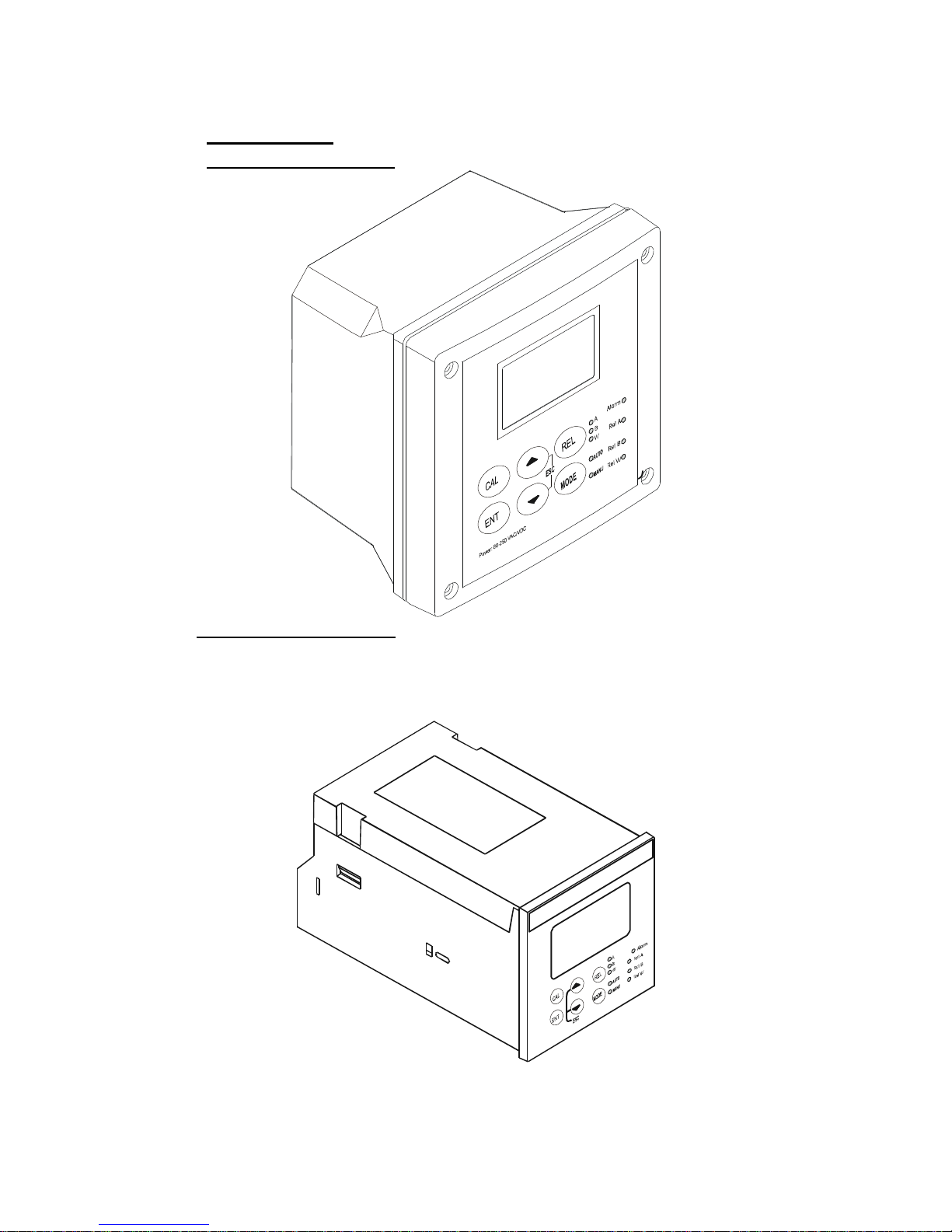
control. The controller is available in two versions, one for panel mounting
and one for wall mounting in an enclosure. The controller can be used for
applications such as water treatment and monitoring, galvanicdecontamination, chemical processing, food processing, clean or wastewater
control and neutralization processes.
This controller has many user-friendly and safety features which include:
• Menu-driven program that simplifies set-up.
• Built-in non-volatile memory to ensure that calibration and other
information are not erased if power supply fails.
• Push-button for calibration and electrode offset adjustment from the
keypad.
• Automatic temperature compensation (ATC).
• Manual temperature compensation setting without the ATC probe, with
independent setting for calibration and process temperature.
• Two galvanically isolated current outputs 0/4...20mA
• 0 to 1999 seconds time delay adjustment on all relays – minimizes false
alarms.
• Separately adjustable high and low set-point hysteresis (dead bands)
prevent chattering of relays around the set points.
• Asymmetrical/symmetrical input for pH/ORP mode of operation.
• Three control modes: limit controller, P controller and PI controller (P/PI
controller as pulse length or pulse frequency).
• Large dual display LCD for easy reading with clear multiple annunciators,
alarm status, operational and error messages.
• Two switching contacts as set-point relays.
• Separate alarm relay alerting you to set point limits exceeded for a certain
time and if the Pt100/Pt1000 wires are broken or disconnected during the
ATC function.
• Wash relay.
• Hold function to freeze output current (0/4...20mA) and release control
relays.
• LED indicators signal control activities to visually monitor transmitter status
from a distance.
• Protection against electromagnetic interference.
• Back lit and UV light protected LC display
Page 11
2.2 Measurement and Control System
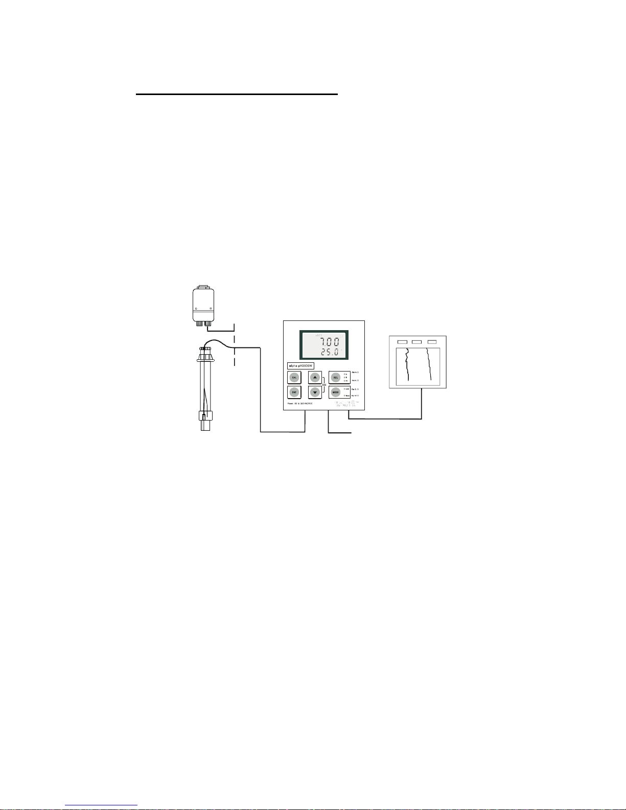
A typical measurement system consists of:
• a pH/ORP process controller
• a pH/ORP combination electrode with integrated or separate temperature
sensor Pt 100/1000,
• an appropriate pH or ORP measurement cable
• an immersion, flow or process assembly with or without a potential
matching pin (PMP)
• a final control element such as pump or valve
• a chart recorder
Power Mains
(220/110VAC)
Flow Assembly
MeasurementCable
Process Assembly
with Electrode
Chart Recorder
pH Controller
Page 12
2.3 Unit Overview
Wall mounting version
Panel mounting version
Page 13
2.3.1 Display overview
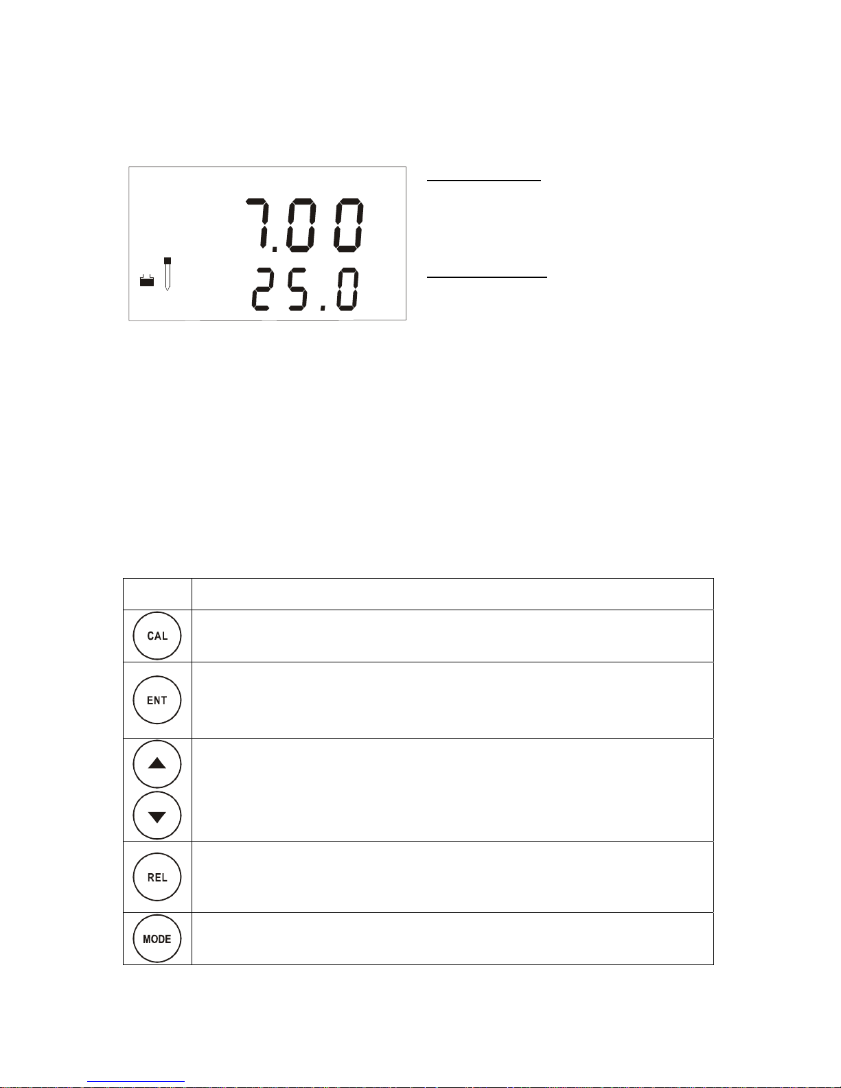
The LC display shows two alpha-numerical fields for parameters and measured
values as well as various mode and status indicators.
Mode indicators:
– MEAS: Measurement mode
– SETUP: Set-up mode
– CAL: Calibration mode
Status indicators:
– READY: Visible after successful
calibration
– HOLD: Unit in “HOLD” mode
– ATC: Visible in ATC (Automatic
Temperature Compensation) mode. Not
visible in the Manual temperature
compensation mode. “ATC” flashes if the
temperature probe is faulty in its ATC
mode
– ERR: Error indicator
– S: Visible in symmetrical measurement
mode
MEAS
P
H%
SETUP
CAL
HOLD
O
C
s
p
atc
m
v
h
ready
err
O
f
2.3.2 Key functions
Key
Description
– Enter Calibration mode (requires access code)
– Enter Set-up mode (requires access code)
– Access sub functions (parameters) within a function group of Set-up mode
– Confirm (store) set-up parameters and numerical values
– Start calibration in Calibration mode
– Select function group in the Set-up mode.
– Set parameters and numerical values(if key is pressed continuously, the
setting speed increases)
– Control the relays in MANUAL relay operation
– Returns to “Measurement mode” when both keys are pressed simultaneously
– Display limit values for SP1 and SP2 and settings for wash contact in AUTO
relay operation
– Toggle between RELAY A, RELAY B or Wash relay in MANUAL relay
operation
– Switch from AUTO to MANUAL relay operation (requires access code)
Page 14
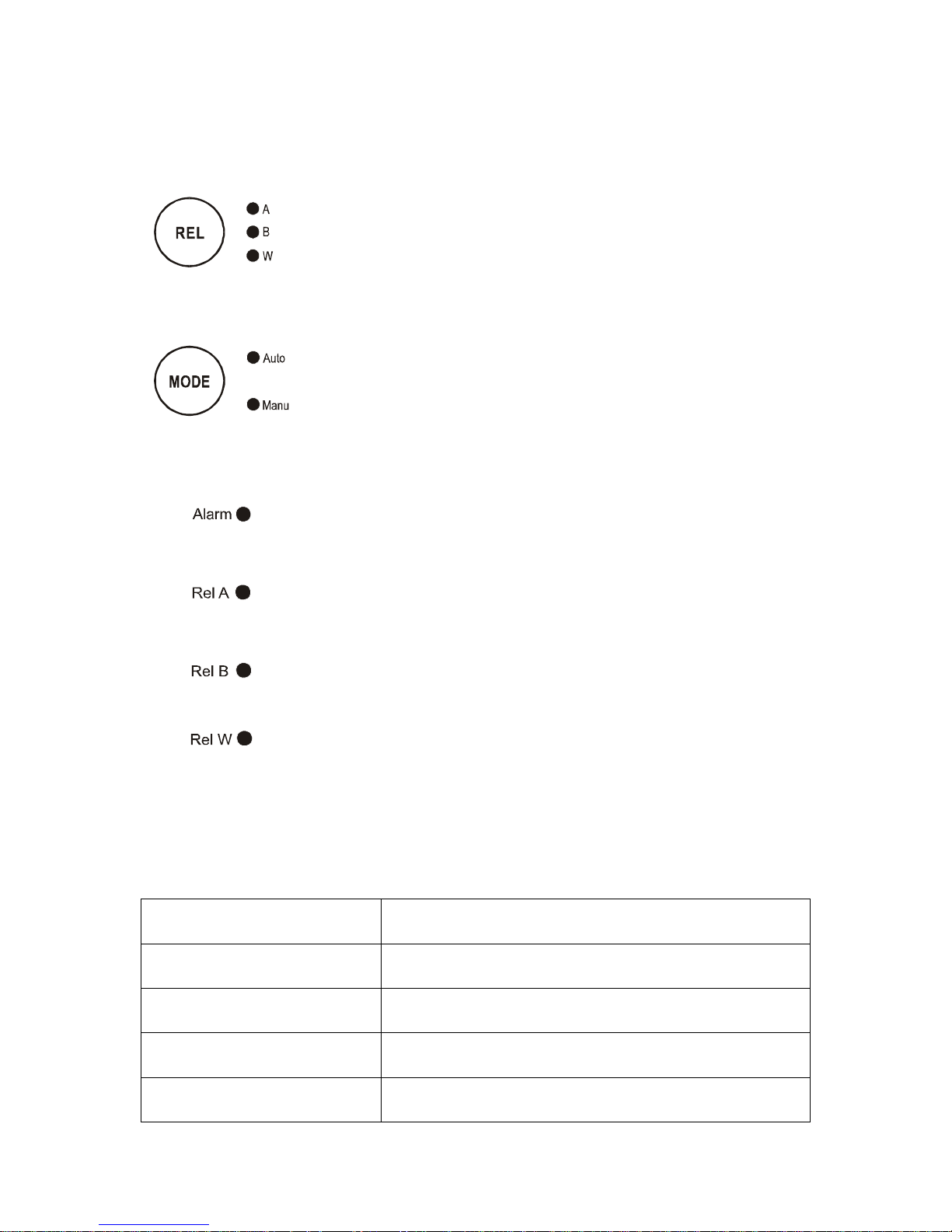
LED indicators
Relay indicators
If REL key is pressed the LED (A, B or W) indicates to which
Relay (A, B or Wash) the displayed limit values refer.
Relay mode indicators
Auto LED lights if relay operation is set to automatic mode.
Manu LED lights if relay operation is set to manual mode.
Relay status indicators
This LED lights if limit value is exceeded or the ATC probe
fails.
This LED lights green if measured value is within the limit for
Relay A or lights red if measured value exceeds limit.
This LED lights green if measured value is within the limit for
Relay B or lights red if measured value exceeds limit.
This LED lights if cleaning cycle is on.
2.3.3 Security codes
The access to Calibration mode, Setup mode and Manual relay operation
mode is protected with security codes. The security codes are set at the
factory and cannot be changed by the user. The following security codes are
used:
Security code Mode Description
000 View only mode to view actual settings
11 Calibration mode to start calibration
22 Setup mode to configure parameters
22 Manual relay operation to switch relay operation mode
from automatic to manual
Page 15
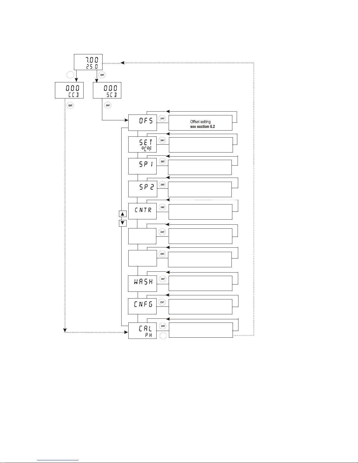
Menu overview
SETUP
HOLD
SETUP
HOLD
SETUP
HOLD
SETUP
HOLD
SETUP
HOLD
SETUP
HOLD
cur.1
SETUP
HOLD
cur.2
SETUP
HOLD
SETUP
HOLD
MEAS
P
H
O
C
SETUP
HOLD
Temperature settings
see section 6.3
Relay A (set point 1) setti ngs
see section 6.4
Relay B (set point 2) settings
see section 6.4
Controller settings
see section 6.5
Current output 1 settings
see section 6.6
Current output 2 settings
see section 6.7
Wash contact settings
see section 6.8
Unit settings
see section 6.9
Calibration
see secti o n 5
CAL
ENTERENTER
CAL
*CCD “000”= Check calibration parameters (View only mode)
CCD “11” = Calibration mode
** SCD “000” = Check setup parameters (View only mode)
SCD “22” = Setup mode
Page 16
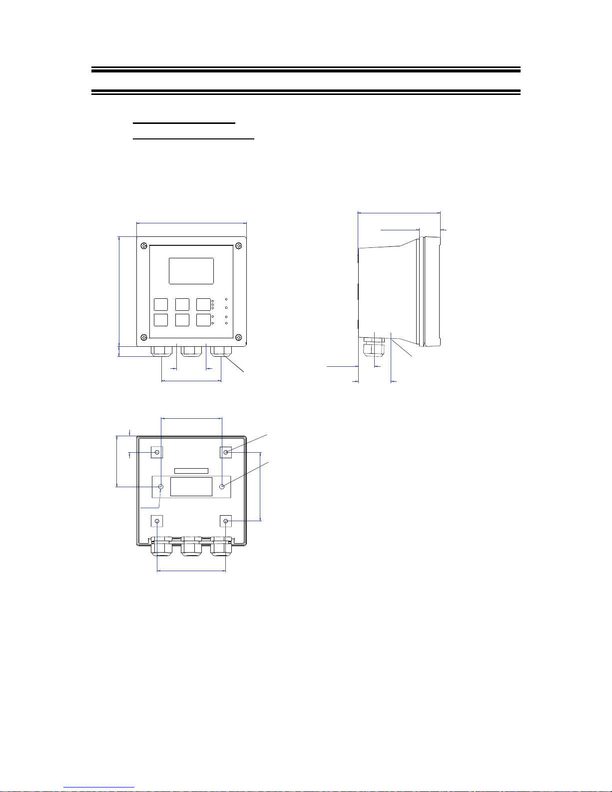
3 ASSEMBLY AND INSTALLATION
3.1 Mounting the unit
Wall Mounting Version
approx. 14 [.55]
39 [1.54]
Holes for wall
mounting (2X)
21.5 [.85]
6 [.24]
144 [5.67]
144 [5.67]
78 [3.07]
111.50 [4.39]
27.5 [1.08]
24 [.94]
66.5 [2.62]
80 [3.15]
90 [3.54]
57.8[2.28]
90 [3.54]
Pg13.5 (3 pcs.)
Holes for post
mounting (4X)
For Pg13.5 cable glands
Unit:
MM [INCH]
Transmitter housing for wall mounting: protection class IP 65
Page 17
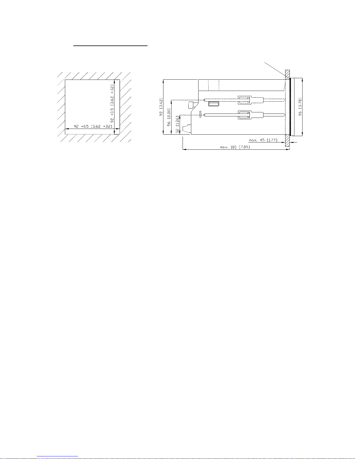
Panel mounting version
Flat gasket 1mm [.04]
(to be inserted by customer)
Panel cut out
UNIT: MM [INCH]
Transmitter housing for panel mounting: protection class IP 54 (front), IP 40 (housing)
Page 18
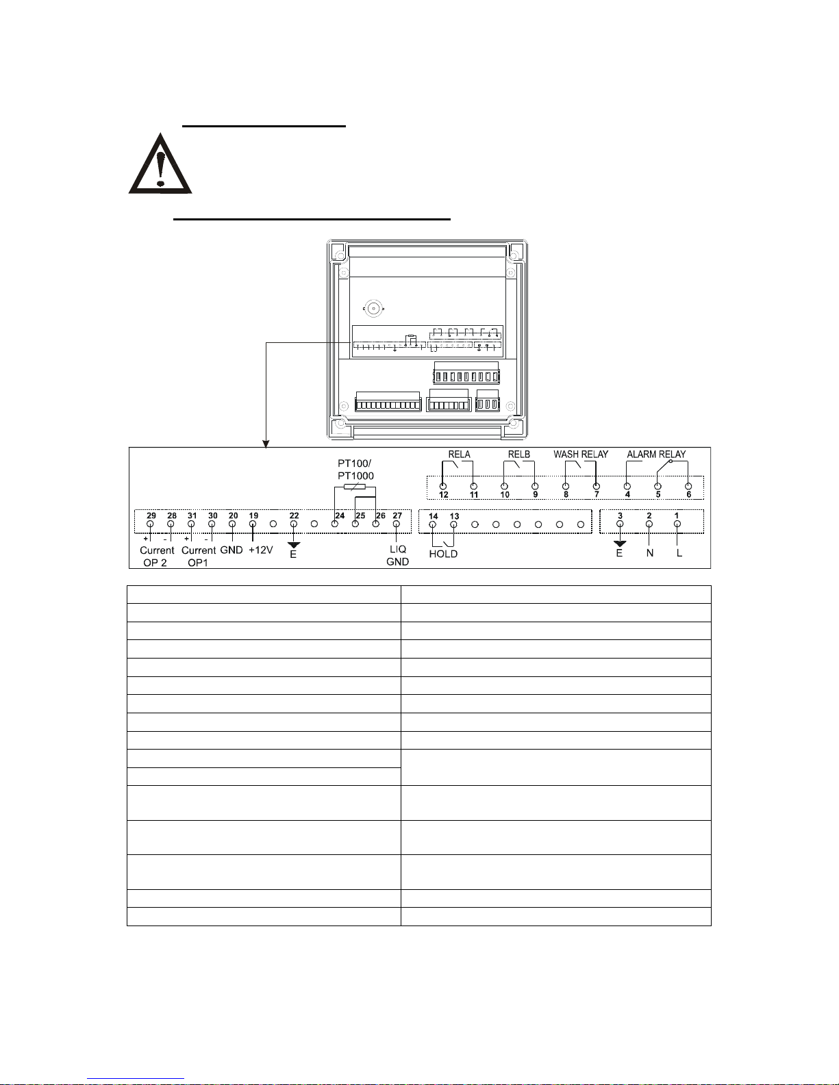
3.2 Connection Diagram
Caution: Ensure electrical mains are disconnected before proceeding.
Connection for wall mounting version
RELA RELB WASH RE LAY ALAR M RELAY
-+
Current
OP 2
29 28 19
GND +12V-+Current
OP1
3031 20E22
PT100/
PT1000
27
LIQ
GND
2524 26
HOLD
14 13
1291011
87
N LE
3421
56
pH/ mV
1. AC mains live wire 17. no connection
2. AC mains neutral wire 18. no connection
3. AC mains protective earth wire 19. 12V Power supply
4. Alarm relay (NO) 20. 12V ground
5. Alarm relay common 21. no connection
6. Alarm relay (NC) 22. Earth ground
7. Wash relay 23. no connection
8. Wash relay 24. Temperature ground
9. Relay B (SP 2) 25. Temperature input
10. Relay B (SP 2) 26. Temperature sense (short to
11. Relay A (SP 1) terminal 25 if using 2- wire RTD)
12. Relay A (SP 1) 27. PMP, liquid ground in symmetrical
ode
13. Hold function 28. 4-20 mA temperature output, -ve
terminal
14. Hold function 29. 4-20 mA temperature output, +ve
terminal
15. no connection 30. 4-20 mA pH output, -ve terminal
16. no connection 31. 4-20 mA pH output, +ve terminal
IMPORTANT: The Alarm relay functions as an “Active Low” device i.e. it switches OFF under
Alarm condition. Therefore the Alarm display device should be connected to the ‘NC’ contacts
of the relay (5 & 6).
Page 19

NOTE:
Switch or circuit breaker shall included in the building installation.
It shall be in close proximity to the equipment and within easy reach of the
operator.
It shall be marked as the disconnecting device for the equipment.
Page 20
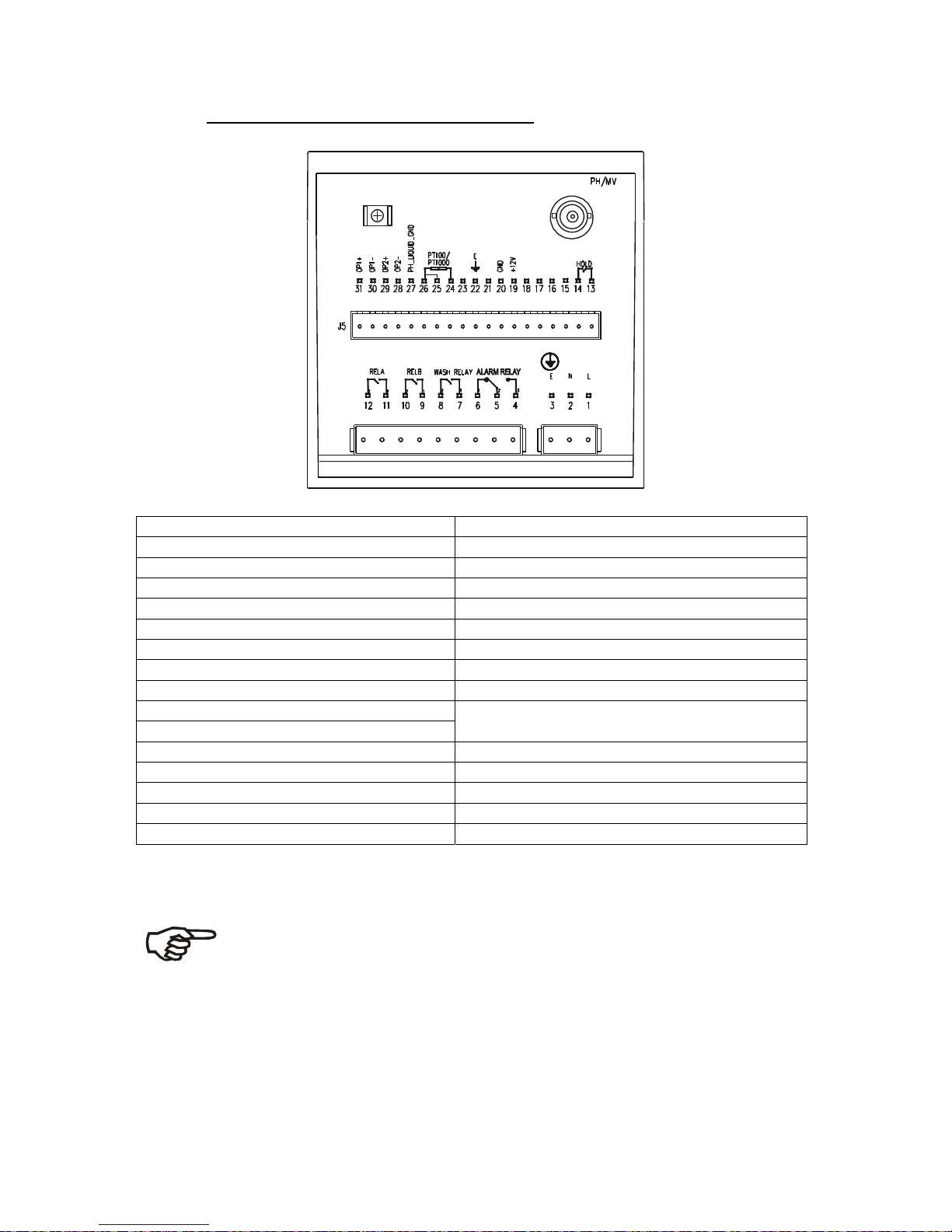
Connection for panel mounting version
1. AC mains live wire 17. no connection
2. AC mains neutral wire 18. no connection
3. AC mains protective earth wire 19. 12V Power supply
4. Alarm relay (NO) 20. 12V ground
5. Alarm relay common 21. no connection
6. Alarm relay (NC) 22. Earth ground
7. Wash relay 23. no connection
8. Wash relay 24. Temperature ground
9. Relay B (SP 2) 25. Temperature input
10. Relay B (SP 2) 26. Temperature sense (short to terminal 25 if
11. Relay A (SP 1) using 2- wire RTD
12. Relay A (SP 1) 27. PMP, liquid ground in symmetrical mode
13. Hold function 28. 4-20 mA temperature output, -ve terminal
14. Hold function 29 4-20 mA temperature output, +ve terminal
15. no connection 30. 4-20 mA pH output, -ve terminal
16. no connection 31. 4-20 mA pH output, +ve terminal
IMPORTANT: The Alarm relay functions as an “Active Low” device i.e. it switches OFF under
Alarm condition. Therefore the Alarm display device should be connected to the ‘NC’ contacts
of the relay (5 & 6).
NOTE:
Switch or circuit breaker shall included in the building installation.
It shall be in close proximity to the equipment and within easy reach of the
operator.
It shall be marked as the disconnecting device for the equipment.
Page 21
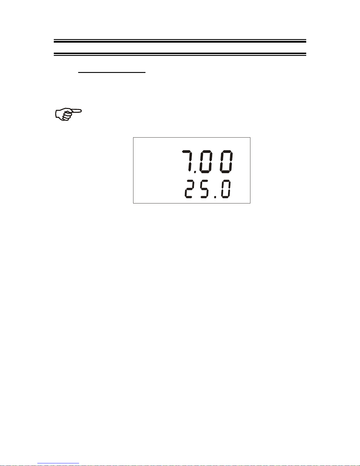
4 NORMAL OPERATION
4.1 Measurement mode
When the controller is powered on, the display first shows all segments
briefly, then the transmitter automatically enters into the Measurement
mode.
Please note: To guarantee accurate readings the measuring system
(controller and sensor) must be calibrated.
MEAS
P
H
O
C
The mode indicator “MEAS” at the top of the display indicates that the
controller is in Measurement mode. The upper alpha-numerical display
shows the measured pH or ORP value, while the lower display shows either
the temperature value if the controller is set for pH measurement, or “ORP” if
it is set for ORP measurement.
The annunciators “pH”, “mV” or “%” at the upper right side of the display
indicate the current measurement mode setting whether the controller is set
for pH, mV or ORP % measurement.
From Measurement mode you can access Calibration mode and Setup
mode by pressing the CAL key or ENT key followed by the corresponding
security code. For detailed information refer to section 5 “Calibration
mode” or section 6 “Setup mode”, respectively.
By pressing the REL key in Measurement mode you can view the actual
relay set points. By pressing the MODE key in Measurement mode you can
switch relay operation mode from automatic to manual.
For detailed information refer to section 7 “Relay Modes”.
Page 22
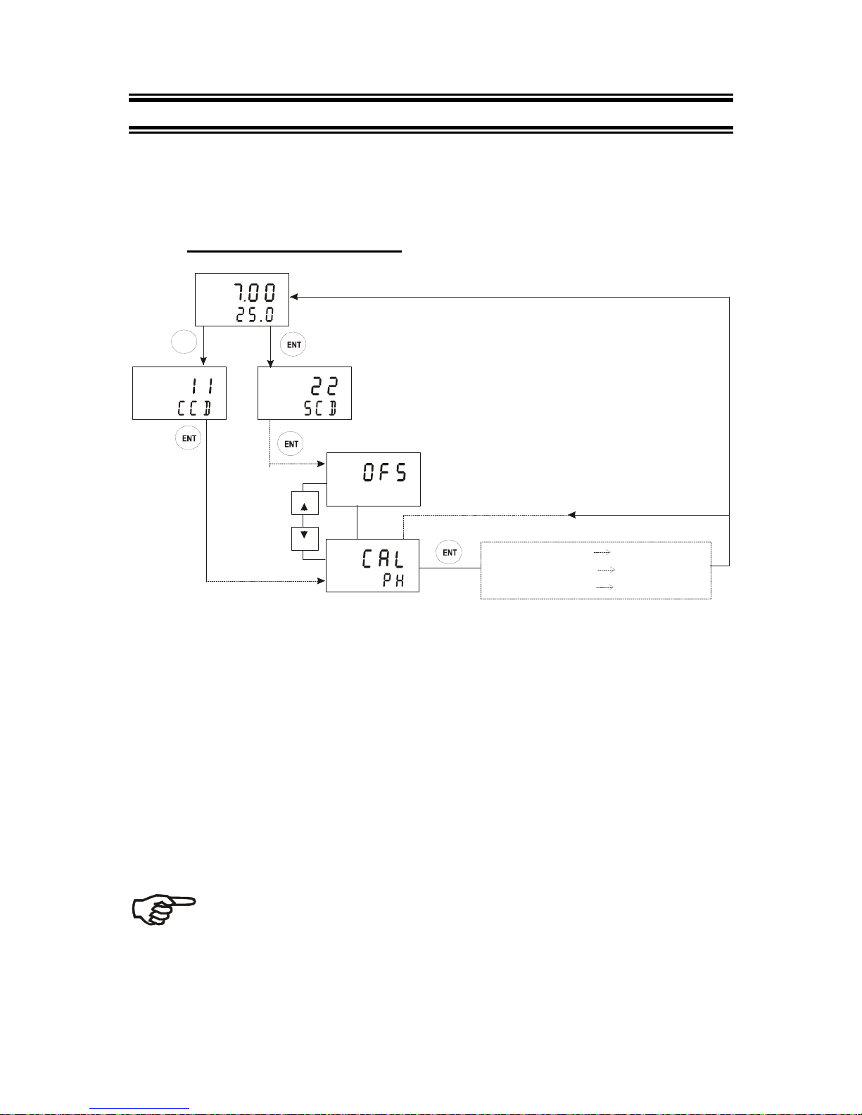
5 CALIBRATION MODE
You can access the Calibration mode directly from the Measurement mode
by pressing the CAL key and entering the Calibration security code “11”.
Calibration mode may also access via the Setup mode (see section 6.1).
5.1 Entering Calibration mode
ENTERENTER
ENTERENTER
ENTERENTER
ENTERENTER
MEAS
P
H
O
C
CAL
SETUP
HOLD
SETUP
HOLD
pH calibration
ORP-mV calibration
ORP-% calibra tion
see section 5.2
see section 5.3
see section 5.4
1. While in Measurement mode press the CAL key (direct access) or ENT
key (access via Setup mode).
2. If CAL key was pressed: The display prompts you to enter the calibration
security code. Press the ▲ or ▼ key to set the calibration security code
to “11”, then press the ENT key to confirm the calibration security code.
3. If ENT key was pressed: The display prompts you to enter the security
code. Press the ▲ or ▼ key to set the security code to “22”. Press the
ENT key to confirm the security code, then press the ▲ or ▼ key to
select the calibration sub-function.
If configured for pH control, the display shows “CAL PH”. If configured for
ORP control, the display shows “CAL ORP”. To start calibration, refer to the
corresponding section (see illustration above).
Note: to exit Calibration mode at any time press the ▲ and▼ key
simultaneously (escape). The controller returns to the Measurement
mode and the old calibration values remain active. The calibration
security code automatically resets from “11” to “000” after the controller
returns to Measurement mode.
Page 23
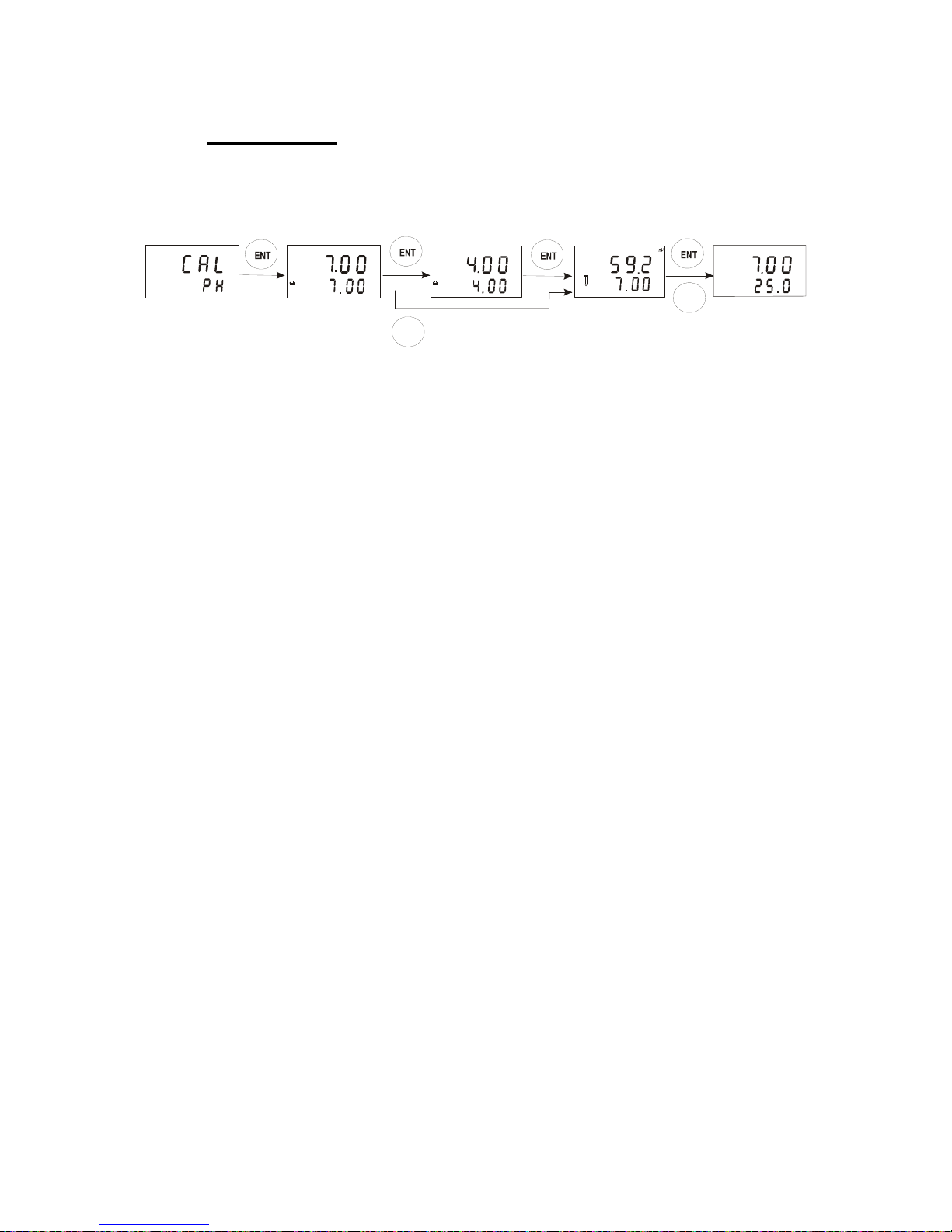
5.2 pH Calibration
This controller unit features one-point or two-point calibration with five preset
buffer sets. Buffer values refer to 25 °C. To calibrate the instrument, you
need a standard pH buffer solution that matches one of these values.
two-point calibration
SETUP
HOLD
P
H
CAL
HOLD
P
H
P
H
CAL
HOLD
P
H
P
H
CAL
MEAS
P
H
O
C
atc
CAL
CAL
one-point calibration
1. Enter Calibration mode as described in section 5.1. The display should
read “CAL PH” (for pH calibration).
Note: If the display reads “CAL OrP”, see section 6.9 for procedures on how
to switch from ORP to pH readings.
2. Press the ENT key to start calibration. The “CAL” indicator appears at the
top of display and the buffer indicator appears in the bottom corner of the
display. The display shows the actual pH reading (upper value) and the
buffer value for zero point (lower value). For the offset (zero point)
calibration, there are two values to choose from. They are pH 7.00 or pH
6.86. Using the ▲ and ▼ keys, choose the value that matches with the
buffer used.
3. Place the electrode in the first buffer solution. In ATC mode, you m ust also
immerse the temperature probe in the buffer solution. Likewise for
symmetrical mode, you must also immerse the potential matching pin in
the buffer.
4. You can conduct either a one-point or a two-point calibration: Press the
ENT key for two point calibration or the CAL key for one point
calibration. The electrode indicator and CAL indicator both flash. The
controller automatically adjusts the reading to match the buffer value.
5. If one-point calibration was selected, the display will show the slope and
offset. If two-point calibration was selected, the lower section of the display
will now show its next lower “pH” buffer. Use ▲ and ▼ keys to select the
second buffer from one of these preset values: - pH 1.68, pH 4.01, pH
9.00, pH 9.18 and pH 10.01. Remove the electrode from the first buffer,
wash and then immerse it into the second buffer. Press the ENT key, the
electrode and CAL indicators will flash. The controller adjusts the reading
to the second buffer.
6. After calibrating with the second buffer value, the controller will
automatically display the slope in the upper and the zero point in the lower
section of the display.
Note: You can also view the values for zero point and slope without
calibration (see section 5.1.2 for instruction). The zero point and slope are redetermined after each calibration.
Page 24
7. Press the ENT key to return to the Measurement mode.
Note: If you entered the Calibration mode from the Setup mode, the controller
will return to the setup menu.
Note: If there is a calibration error the transmitter displays “ERR”. In
this case, press the ▲ and ▼ keys simultaneously (escape) to
restart the calibration beginning from step 1.
Note: When calibrating with manual temperature compensation, the
controller automatically changes from the preset process temperature
to the calibration temperature. After leaving the Calibration mode, the
controller switches back to the process temperature (for setting the
calibration temperature and the process temperature, see section 6.3).
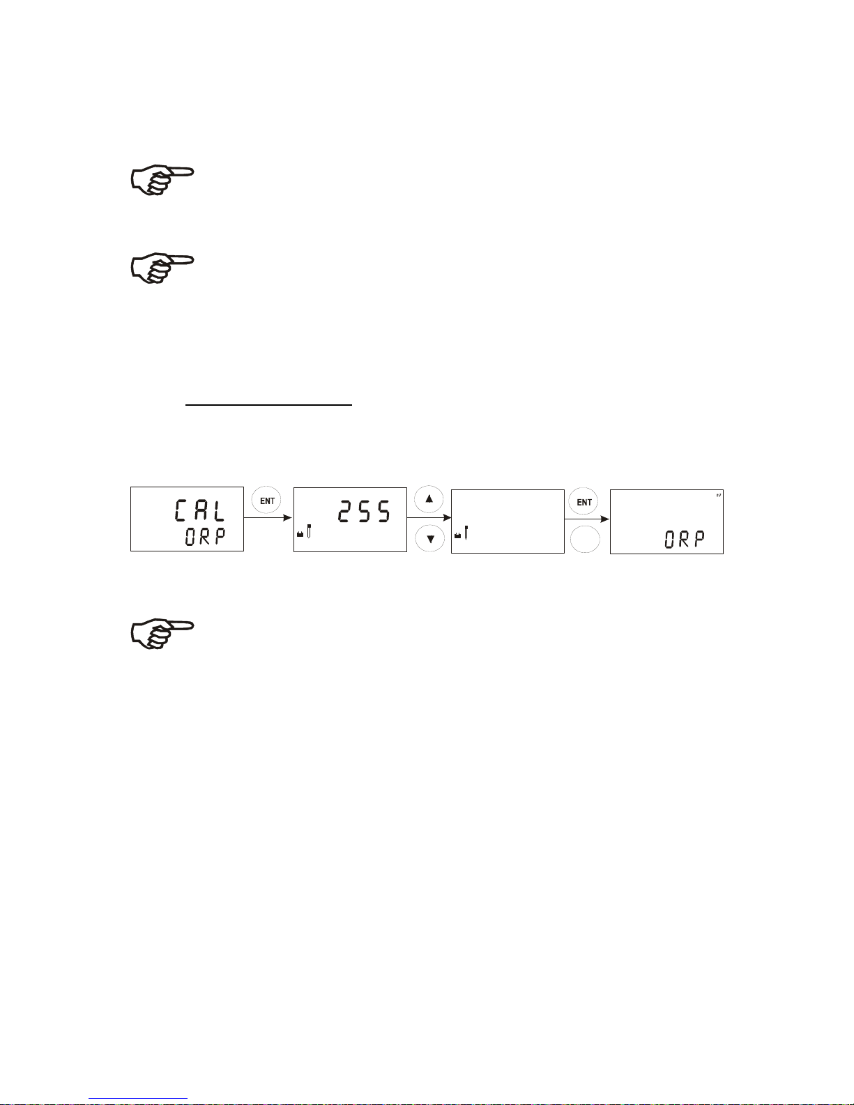
5.3 ORP–mV Calibration
If controller is configured for ORP-mV measuring you can perform only a
one-point calibration.
meas
SETUP
HOLD
CAL
HOLD
M
V
CAL
HOLD
M
V
CAL
250
250
1. Enter Calibration mode as described in section 5.1. The display
should read “CAL ORP”.
Note: If the display reads “CAL PH”, see section 6.9 for procedures on
how to switch from pH to ORP-mV readings.
2. Place sensor in the ORP solution.
3. Press the ENT key to start calibration. The “CAL” indicator appears on
the display. The display shows the current mV output of the electrode
without any offset adjustment.
4. Press the ▲ or ▼ key to match the mV value to your exact reading.
5. Press the ENT key to confirm. The controller calculates the correction
factor and returns to the Measurement mode.
Page 25
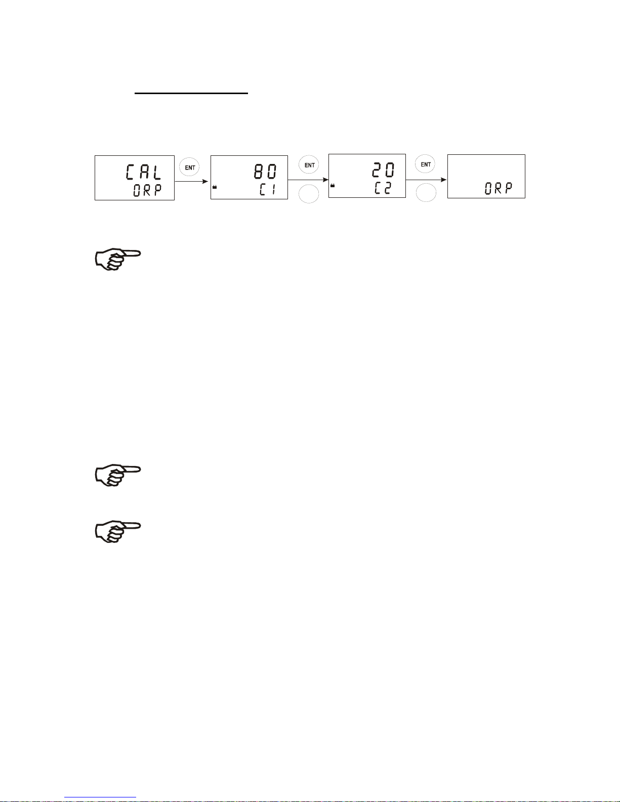
5.4 ORP -% Calibration
If controller is configured for ORP-% measuring you can perform a calibration
at two points using a low concentration sample (20%) and a high
concentration sample (80%). To calibrate the controller for ORP %:
CAL
CAL
meas
59.0
%
CAL
HOLD
SETUP
HOLD
CAL
HOLD
1. Enter Calibration mode as described in section 5.1. The display should
read “CAL ORP”.
Note: If the display reads “CAL PH”, see section 6.9 for procedures on
how to switch from pH to ORP-% readings.
2. Press the ENT key to start calibration. The display prompts you to place
the sensor in the high concentration sample (relative value of 80%).
3. Place sensor in the high concentration sample, then press the ENT key.
The electrode and CAL indicators flash. The unit automatically adjusts its
reading to match the solution value.
4. The display prompts you to place the sensor in the low concentration
sample (relative value of 20%). Remove the electrode from the first
standard, wash it well and then immerse it in the 20% standard.
5. When the display stabilizes press the ENT key. The “CAL” indicator
flashes and the controller adjusts its display to the 20% relative value and
exits to the Measurement mode.
Note: If there is a calibration error, the transmitter displays “ERR”. In
this case press the ▲ and ▼ keys simultaneously (escape) to
restart the calibration, beginning from step 1.
Note: If you stop calibration after entering the first value, or if
calibration is defective, the controller will use its original calibration
data.
Page 26
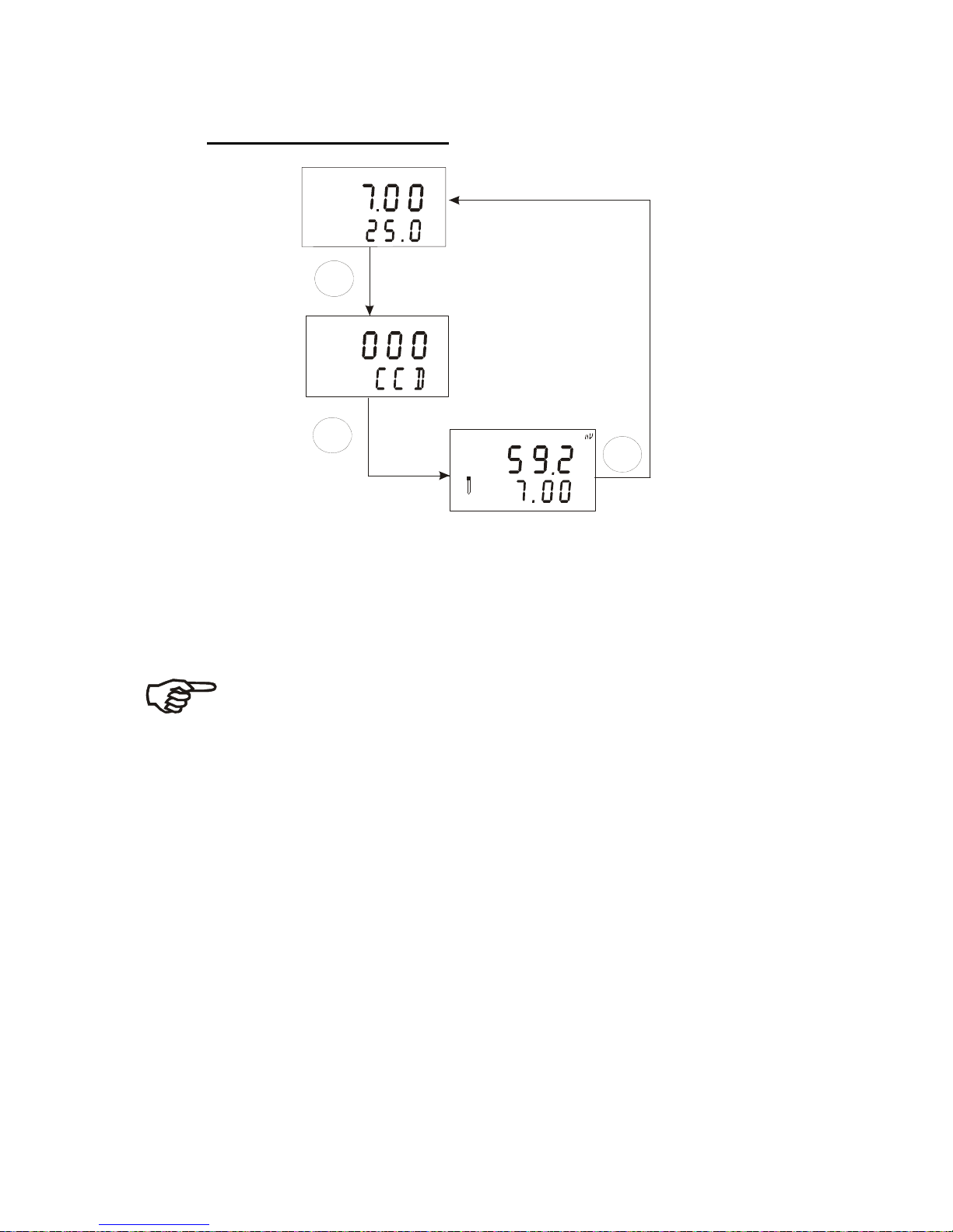
5.5 View actual zero and slope
ENT
ENT
CAL
P
H
CAL
MEAS
P
H
O
C
atc
1. While in Measurement mode press the CAL key. The display will prompt
you to enter a security code. Leave the security code at “000” (view only
mode).
2. Press the ENT key.
The display shows the slope in mV (upper value) and the pH reading at 0 mV
(zero point, lower value).
Note: If no key is pressed for 30 seconds the transmitter
automatically returns to the Measurement mode.
3. Press the ENT key to return to the Measurement mode.
Page 27
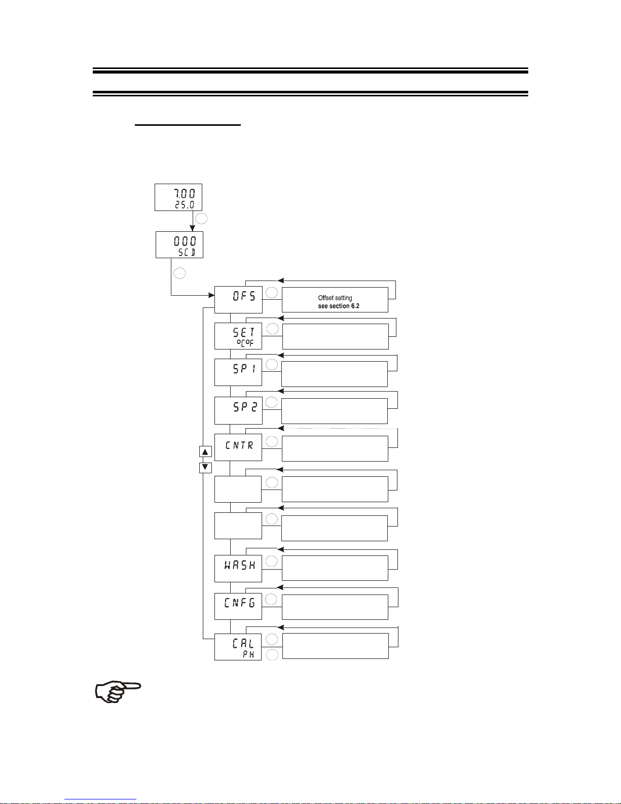
6 SET-UP MODE
6.1 Enter Setup mode
In the Setup mode the controller can be configured to your individual
requirements.
MEAS
P
H
O
C
ENTER
ENT
ENTER
ENT
ENTER
ENT
ENTER
ENT
ENTER
ENT
ENTER
ENT
ENTER
ENT
ENTER
ENT
ENTER
ENT
ENTER
ENT
ENTER
ENT
ENTER
ENT
SETUP
HOLD
SETUP
HOLD
SETUP
HOLD
SETUP
HOLD
SETUP
HOLD
SETUP
HOLD
cur.1
SETUP
HOLD
cur.2
SETUP
HOLD
SETUP
HOLD
SETUP
HOLD
Temperature settings
see section 6.3
Relay A (set point 1) settings
see section 6.4
Relay B (set point 2) settings
see section 6.4
Controller settings
see section 6.5
Current output 1 settings
see section 6.6
Current output 2 settings
see section 6.7
Wash contact settings
see section 6.8
Unit settings
see section 6.9
Calibration
see section 5
CAL
1. While in Measurement mode press the ENT key.
2. The display prompts you to enter the security
code. Set the security code with ▲ or ▼ key to:
–“SCD22” if you want to change parameter settings
–“SCD000” if you want to view only parameter settings (view
only mode)
3. Press the ENT key.
Note: to exit Setup mode at any time press the ▲ and ▼ key
simultaneously (escape). The controller returns to the Measurement mode.
Page 28
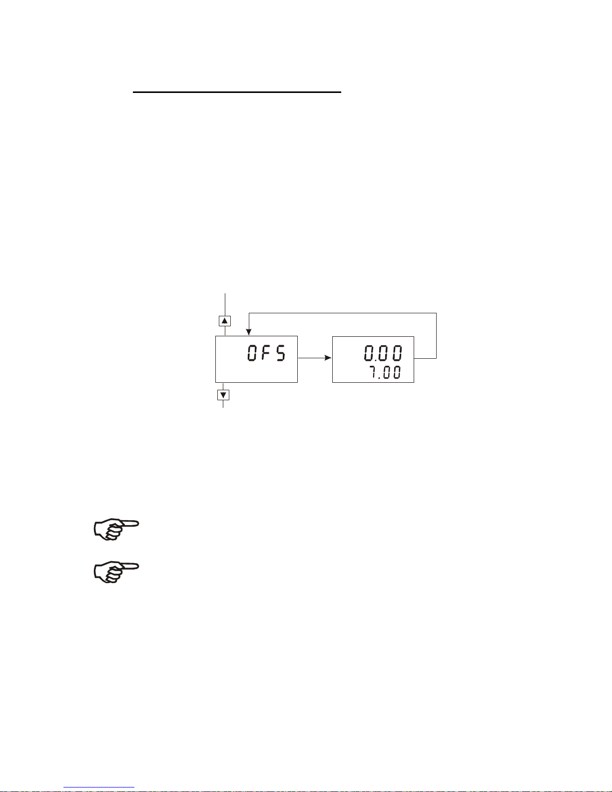
6.2 Electrode Offset (OFS) sub-function
The electrode offset sub-function is only available if the controller is
configured for pH measuring. Use this sub-function to set an offset that
corrects the readings without removing the electrode from the control system.
The setting range is ±120 mV.
The controller will add or subtract the offset value from the measured pH and
display the corrected value. However, if you need to offset the value beyond
the average offset you would expect in your application type, consider a full
calibration or even electrode replacement.
1. Take a sample from the system. Record the controller's pH reading at the
time you take the sample.
2. Measure the pH value of your sample using a calibrated pH tester, handheld meter, or bench meter. Record the correct pH value.
3. Select the “OFS” sub-function, then press the ENT key.
SETUP
HOLD
P
H
SETUP
HOLD
P
H
4. The display shows the current measured pH value (lower value) and the
current offset value (upper value). Press the ▲ or ▼ key to adjust the
pH value noted in Step 2. As the ▲ and ▼ keys are being pressed to
adjust the pH value, the offset value also changes. Press the ENT key to
confirm the new offset value.
5. Continue with additional Setup procedures, or return to the Measurement
mode by pressing the ▲ and ▼ keys (escape) simultaneously.
Note: The offset value is reset during full calibration. See section 5 for
full calibration instructions.
Note: The offset sub-function is blanked out during ORP operation.
Page 29
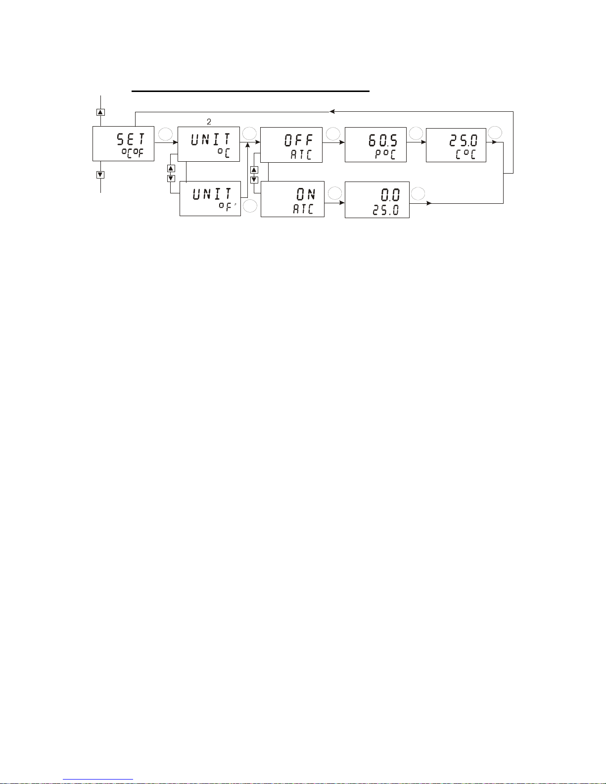
6.3 Setting temperature (Set
o
C) sub-function
SETUP
HOLD
SETUP
HOLD
O
C
SETUP
HOLD
O
SETUP
HOLD
SETUP
HOLD
O
C
SETUP
HOLD
O
C
atc
SETUP
HOLD
SETUP
HOLD
ENT
ENT
ENT
ENT
ENT
ENT
ENT
1
2
3
3
4
5
6
ENT
1. Select the “SET °C°F” sub-function, then press the ENT key.
2. Selecting temperature unit: press the ▲ or ▼ key to select the desired
temperature unit “°C” or “°F”. Press the ENT key to confirm your selection.
3. Enable/disable ATC mode: press the ▲ or ▼ key to enable (ATC ON)
or disable (ATC OFF) automatic temperature compensation. Press the
ENT key to confirm your selection.
ATC disabled (ATC OFF):
For manual temperature compensation you can set the process and
calibration temperatures. This allows calibration at a temperature other
than the process temperature.
Example: setting a calibration temperature of 25°C lets you calibrate
using standard buffer solutions at 25°C, even if your process temperature
is different from 25°C.
4. Setting the process temperature: press the ▲ or ▼ key to adjust the
process temperature (upper value, setting range: –9.9 to 125°C / 15 to 257
°F). Press the ENT key to confirm process temperature.
5. Setting calibration temperature: press the ▲ or ▼ key to adjust the
calibration temperature (upper value, setting range: –9.9 to 125°C / 15 to
257 °F). Press the ENT key to confirm the calibration temperature.
ATC enabled (ATC ON):
6. Setting temperature offset: The display shows the current temperature
offset (upper value) and the temperature currently measured (lower value).
Compare the current temperature displayed on the controller to a
thermometer known to be accurate. Note down the correct temperature
value. Press the ▲ or ▼ key to adjust the lower value. The upper number
indicates the offset value. You can offset the temperature by up to
±10°C/±18°F. Press the ENT key to confirm your setting.
Continue with additional Setup procedures, or return to the Measurement
mode by pressing the ▲ and ▼ keys (escape) simultaneously.
Page 30
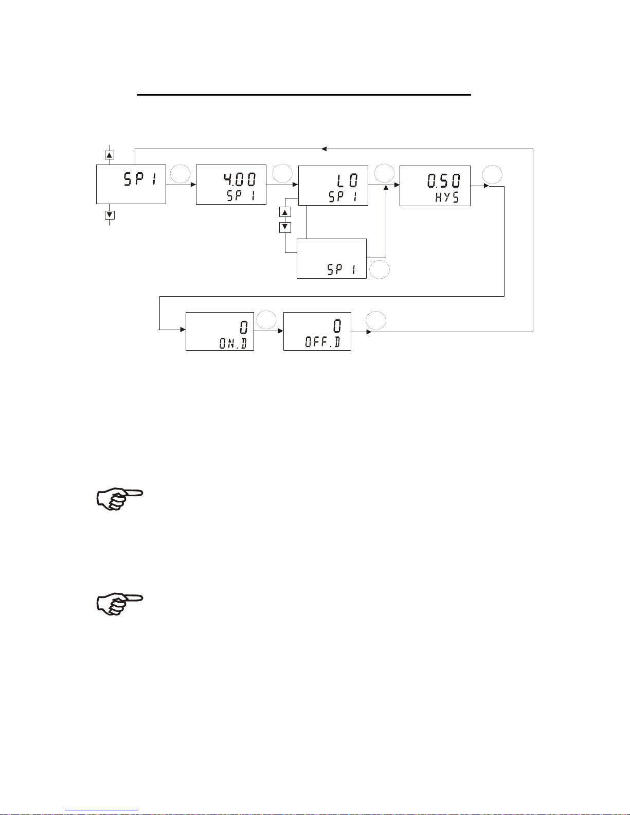
6.4 Control Relay A/Control Relay B (SP1/SP2) sub-function
The SP1 sub-function determines the operating parameters for Relay A;
while SP2 defines the operating parameters for Relay B. Since these groups
have the same set-up parameters, they are described together.
SETUP
HOLD
SETUP
HOLD
SETUP
HOLD
SETUP
HOLD
SETUP
HOLD
SETUP
HOLD
hi
1
2
5
6
3
3
4
ENT
ENT
ENT
ENT
ENT
ENT
ENT
P
H
SETUP
HOLD
1. Select the “SP1” (Relay A) or “SP2” (Relay B) sub-function, then press
the ENT key.
2. Setting set point value: press ▲ or ▼ key to enter the value for set
point 1 (set point 2) at which your controller will activate. Press the ENT
key to confirm your setting.
3. Selecting relay function: press the ▲ or ▼ key to select the desired
relay function (“LO”= low or “HI”= high). Press the ENT key to confirm
your selection.
Note: This parameter lets you choose the relay function. Select “LO” to
activate the relay when the pH/ORP value undershoots the set point;
select “HI” to activate the relay when the value overshoots the set point.
SP1 and SP2 can be selected as “Lo/Lo”, “Lo/Hi”, “Hi/Lo”, or “Hi/Hi”.
4. Setting a hysteresis value: press the ▲ or ▼ key to select the desired
hysteresis (setting ranges: 0.1 to 1.0 pH, 10 to 100mV or 1 to 10%) for set
point 1 (set point 2). Press the ENT key to confirm your setting.
Note: Hysteresis prevents rapid contact switching if the measured value
is fluctuating near the set point. Please refer to Appendix 3 for a
graphical representation of the hysteresis.
Example: You have set your high set point at pH 10.0 and your
hysteresis value at pH 0.5. If your measured value overshoots pH 10.0,
the controller’s relay activates. The actions of the external device will
cause the solution’s pH to drop. The relay will deactivate, when the pH value drops below 9.5 pH.
5. Setting the on-delay time lag: press the ▲ or ▼ key to enter the ondelay time for set point 1 (set point 2). The controller will delay activation of
Page 31

the relay for the number of seconds (0 to 1999 seconds) you select. Press
the ENT key to confirm your setting.
Note: You can set a time delay for each relay, which stops the relay
from switching on the moment the set point is exceeded. This controller
lets you set a 0 to 1999 second time delay before your relay activates.
6. Setting the off-delay time lag: press the ▲ or ▼ key to enter the offdelay time for set point 1 (set point 2). Your controller will delay
deactivation of the relay for the number of seconds (0 to 1999) you select.
Press the ENT key to confirm your setting.
Note: You can set a time delay for each relay, which stops the relay
from switching off the moment the value reaches the set point and
hysteresis. This controller lets you set a 0 to 1999 second time delay
before your relay deactivates.
Continue with Setup mode procedures, or return to Measurement mode by
pressing the ▲ and ▼ keys simultaneously (escape).
Page 32
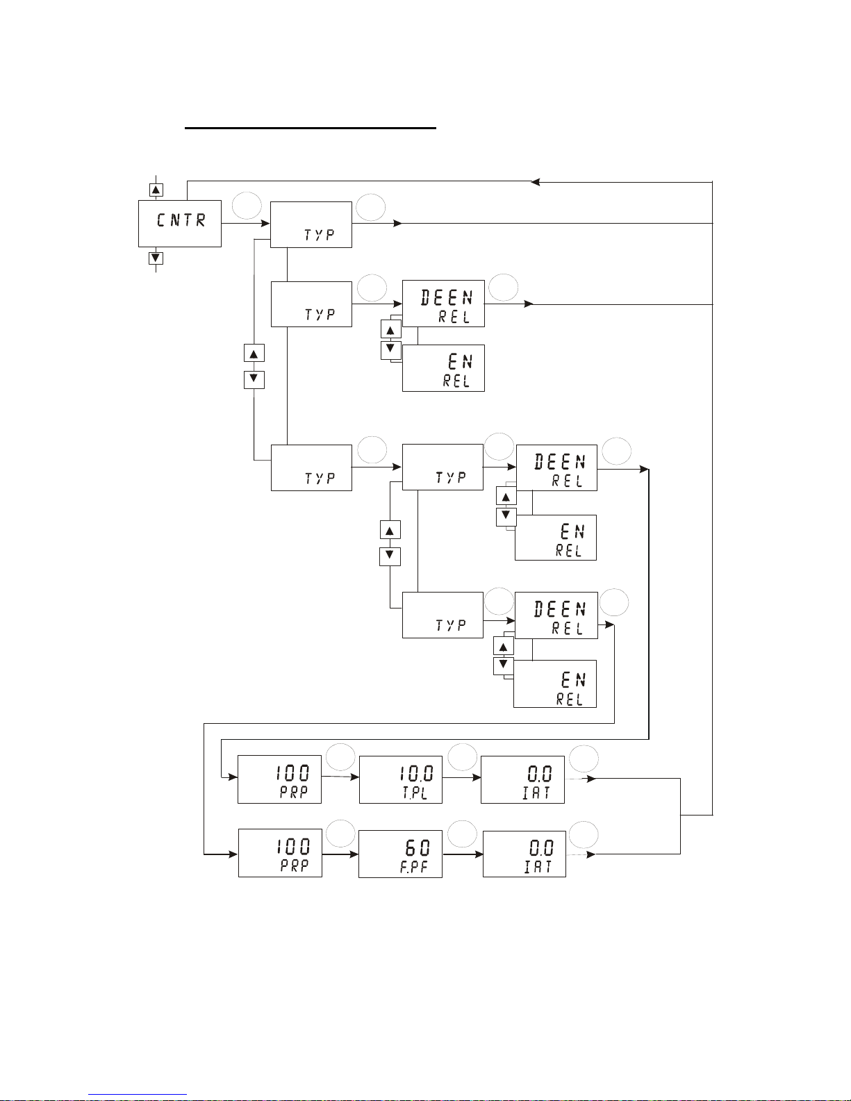
6.5 Controller (CNTR) sub-function
The CNTR sub-function determines the controller’s parameters.
7
8
9
9
10
11
12
5
SETUP
HOLD
SETUP
HOLD
SETUP
HOLD
SETUP
HOLD
SETUP
HOLD
SETUP
HOLD
SETUP
HOLD
SETUP
HOLD
SETUP
HOLD
SETUP
HOLD
SETUP
HOLD
SETUP
HOLD
SETUP
HOLD
SETUP
HOLD
off
SETUP
HOLD
l.ct
SETUP
HOLD
pfc
SETUP
HOLD
plc
SETUP
HOLD
p/pI
1
2
2
2
3
3
4
4
5
6
ENT
ENT
ENT
ENT
ENT
ENT
ENT
ENT
ENT
ENT
ENT
ENT
ENT
ENT
ENT
1. Select the “CNTR” sub-function, then press the ENT key.
2. Selecting the controller type: press the ▲ or ▼ key to select the
suitable controller type:
Page 33

- OFF = controller off
Use control Off to operate controller as a monitor only or to prevent relays
from switching.
- L.CT = limit value control (on/off control).
Use limit control with pumps or values for fast response
- P/PI = proportional/integral control
Use proportional control to operate your pumps smoothly or for precise
control of proportioning valves. Use PI controller to eliminate steady state
error.
Note: please refer to Appendix 4 for detailed information on controller
settings.
Press the ENT key to confirm your selection.
If the controller is set to limit value control (L.CT):
3. Selecting the relay status under Non-Alarm condition: press the ▲ or
▼ key to choose the desired relay status (de-energized = “DEEN” or
energized = “EN”). Press the ENT key to confirm your selection.
- If the controller is set to proportional control (P/PI):
4. Selecting the proportional controller type: press the ▲ or ▼ key to
select the suitable controller type (“PLC” = pulse length control, “PFC” =
pulse frequency control).
Press the ENT key to confirm your selection.
If the proportional controller type is set to pulse length control (PLC):
5. Selecting the relay status under Non-Alarm condition: press the ▲ or
▼ key to choose the desired relay status (de-energized = “DEEN” or
energized = “EN”). Press the ENT key to confirm your selection.
6. Setting the proportional range. Press the ▲ or ▼ key to set the
proportional range (setting range: 10 to 500%). Press the ENT key to
confirm your setting.
7. Setting the pulse length. Press the ▲ or ▼ key to set the pulse length
(setting range: 0.5 to 20 seconds). Press the ENT key to confirm your
setting.
8. Setting the integral action time. Press the ▲ or ▼ key to set the
integral action time (setting range: 0.0 to 999.9 minutes). Press the ENT
key to confirm your setting.
Note: If the integral action time is set to ‘0.0’, then the unit functions as a
‘P’ Controller.
If the proportional controller type is set to pulse frequency control (PFC):
9. Selecting the relay status under Non-Alarm condition: press the ▲ or
▼ key to choose the desired relay status (de-energized = “DEEN” or
energized = “EN”). Press the ENT key to confirm your selection.
Page 34
10. Setting the proportional range: press the ▲ or ▼ key to set the
proportional range (setting range: 10 to 500%). Press the ENT key to
confirm your setting.
11. Setting the pulse frequency: press the ▲ or ▼ key to set the pulse
frequency (setting range: 60 to 120 pulses per minute). Press the ENT
key to confirm your setting.
12. Setting the integral action time: press the ▲ or ▼ key to set the
integral action time (setting range: 0.0 to 999.9 minutes). Press the ENT
key to confirm your setting.
Note: If the integral action time is set to ‘0.0’, then the unit functions as a
‘P’ Controller.
Continue with Setup mode procedures, or return to Measurement mode by
pressing the ▲ and ▼ keys simultaneously (escape).
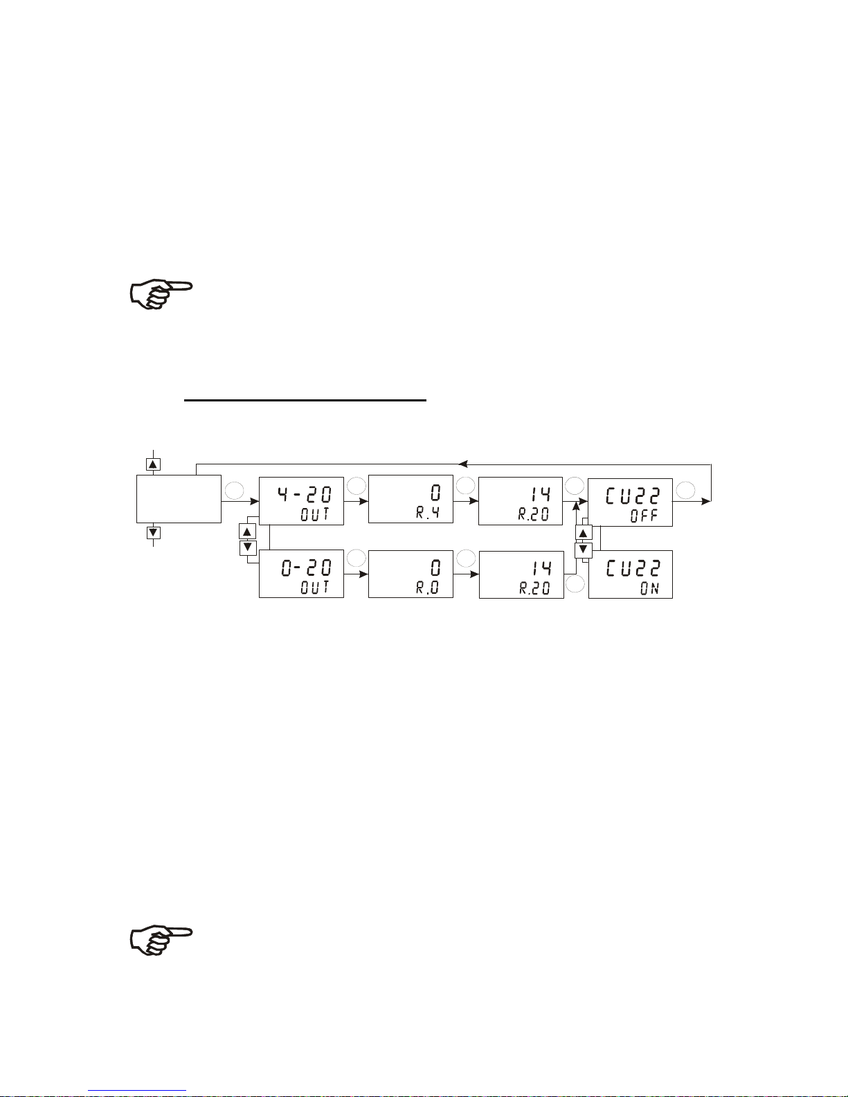
6.6 Current Output 1 sub-function
In this sub-function you set the current output range of the transmitter for pH
or mV values.
2
2
3
3
4
4
5
5
SETUP
HOLD
P
H
SETUP
HOLD
P
H
SETUP
HOLD
P
H
SETUP
HOLD
P
H
SETUP
HOLD
P
H
SETUP
HOLD
SETUP
HOLD
P
H
SETUP
HOLD
1
cur.1
SETUP
HOLD
ENT
ENT
ENT ENT
ENT
ENT
ENT
ENT
1. Select the “CUR.1” sub-function, then press the ENT key.
2. Selecting the output type: press the ▲ or ▼ key to select the desired
output type: 0-20 mA or 4-20 mA. Press the ENT key to confirm your
selection.
3. Setting the pH or ORP value at which the transmitter output will be 4
mA (or 0 mA):
press the ▲ or ▼ key to set the pH or ORP value to be
equivalent to 4 mA or 0 mA, respectively. Press the ENT key to confirm
your setting.
4. Setting the pH or ORP value at which the transmitter output will be 20
mA: press the ▲ or ▼ key to set the pH or ORP value to be equivalent
to
20 mA. Press the ENT key to confirm your setting.
5. Selecting out of range current: Press the ▲ or ▼ key to switch “CU22”
on or off. If “CU22” is on, the output signal will jump to 22 mA when the
measured pH and ORP value is below or above the values set in points 3
& 4 above. Press the ENT key to confirm your setting.
Note: the “CU22” setting (on/off) of current output 1 applies to current
output 2 as well.
Continue with Setup mode procedures, or return to Measurement mode by
pressing the ▲ and ▼keys simultaneously (escape).
Page 35
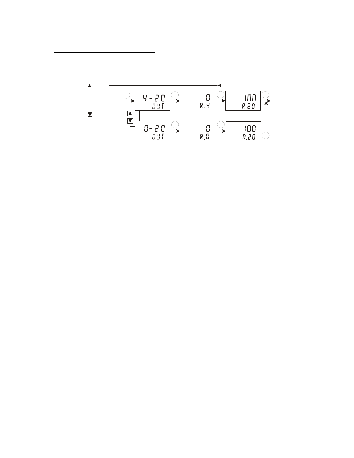
Current Output 2 sub-function
In this sub-function you set the current output range of the transmitter for
temperature values.
ENT
ENT
ENT
ENT
ENT
ENT
ENT
o
c
o
c
o
c
o
c
2
2
3
3
4
4
SETUP
HOLD
SETUP
HOLD
SETUP
HOLD
SETUP
HOLD
SETUP
HOLD
SETUP
HOLD
1
cur.2
SETUP
HOLD
1. Select the “CUR.2” sub-function, then press the ENT key.
2. Selecting the output type: press the ▲ or ▼ key to select the desired
output type: 0-20 mA or 4-20 mA. Press the ENT key to confirm your
selection.
3. Setting the temperature value at which the transmitter output will be
4 mA (or 0 mA): press the ▲ or ▼ key to set the temperature value
(setting range:
-9.9 to 115°C or 15 to 237 °F) to be equivalent to 4 mA (or 0 mA). Press
the ENT key to confirm your setting.
4. Setting the temperature value at which the transmitter output will be
20 mA: press the ▲ or ▼ key to set the temperature value (setting
range: -0.1 to 125°C or 35 to 257 °F) to be equivalent to 20 mA. Press the
ENT key to confirm your setting.
Continue with Setup mode procedures, or return to Measurement mode by
pressing the▲ and ▼ keys simultaneously (escape).
Page 36
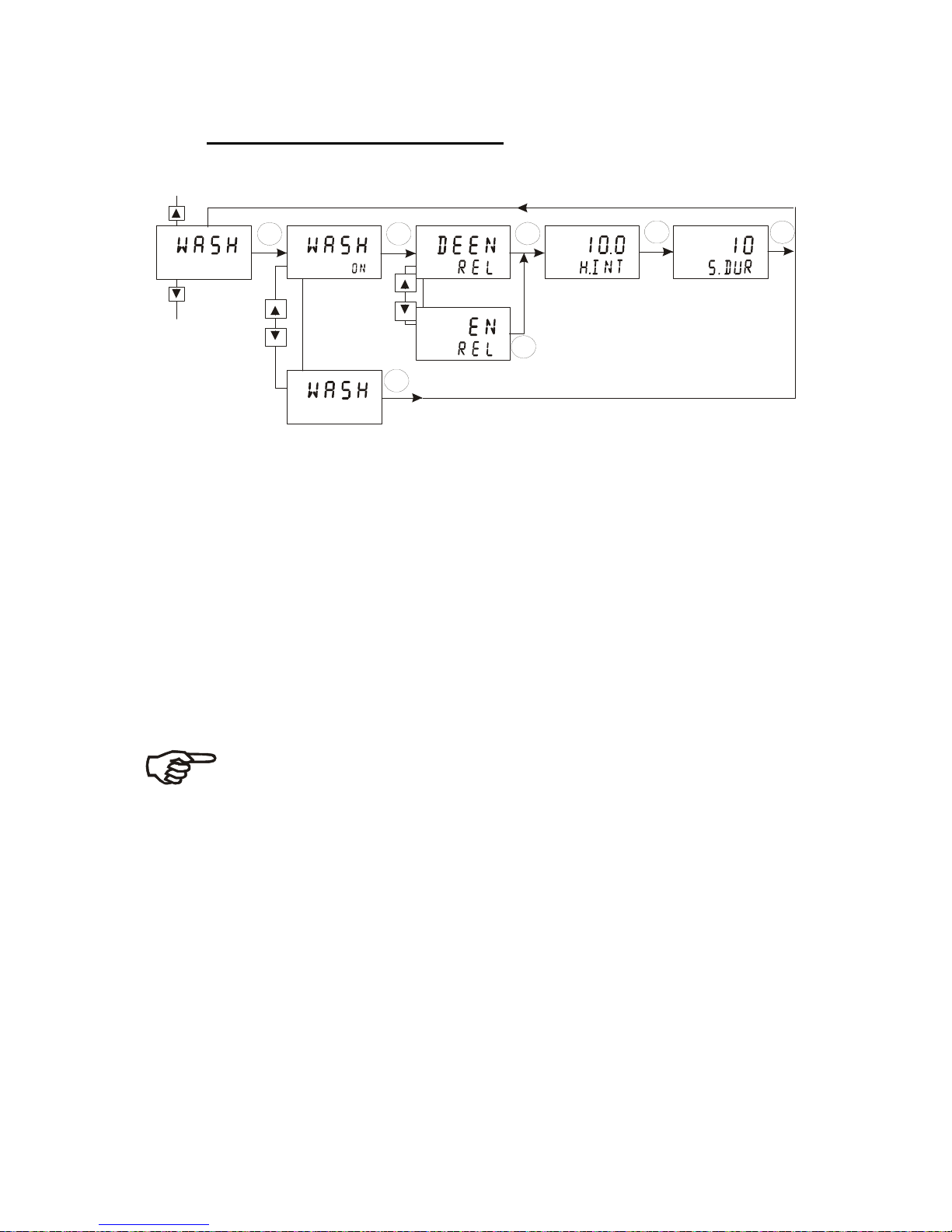
6.7 Wash relay (WASH) sub-function
In this sub-function you set the parameters for the wash relay.
1
2
2
3
3
4
5
ENT
ENT ENT
ENT
ENT
ENT
ENT
SETUP
HOLD
SETUP
HOLD
SETUP
HOLD
SETUP
HOLD
SETUP
HOLD
SETUP
HOLD
SETUP
HOLD
off
1. Select the “WASH” sub-function, then press the ENT key.
2. Enabling/disabling wash function: press the ▲ or ▼ key to enable
(WASH ON) or disable (WASH OFF) wash function. Press the ENT key to
confirm your selection.
3. Selecting the relay status condition: press the ▲ or ▼ key to choose
desired relay status (de-energized = “DEEN” or energized = “EN”). Press
the ENT key to confirm your selection.
4. Setting the wash interval in hours: Press the ▲ or ▼ key to set the
desired wash interval (setting range: 0.1 to 199.9 hours). Press the ENT
key to confirm your setting.
5. Setting the wash duration in seconds: Press the ▲ or ▼ key to set the
desired wash duration (setting range: 1 to 1999 seconds). Press the ENT
key to confirm your setting.
Note: During wash cycle the controller is set to HOLD. For safety
reasons, the HOLD function is activated 5 seconds prior and
deactivated 10 seconds after the wash cycle.
Continue with Setup mode procedures, or return to Measurement mode by
pressing the ▲ and ▼ keys simultaneously (escape).
Page 37
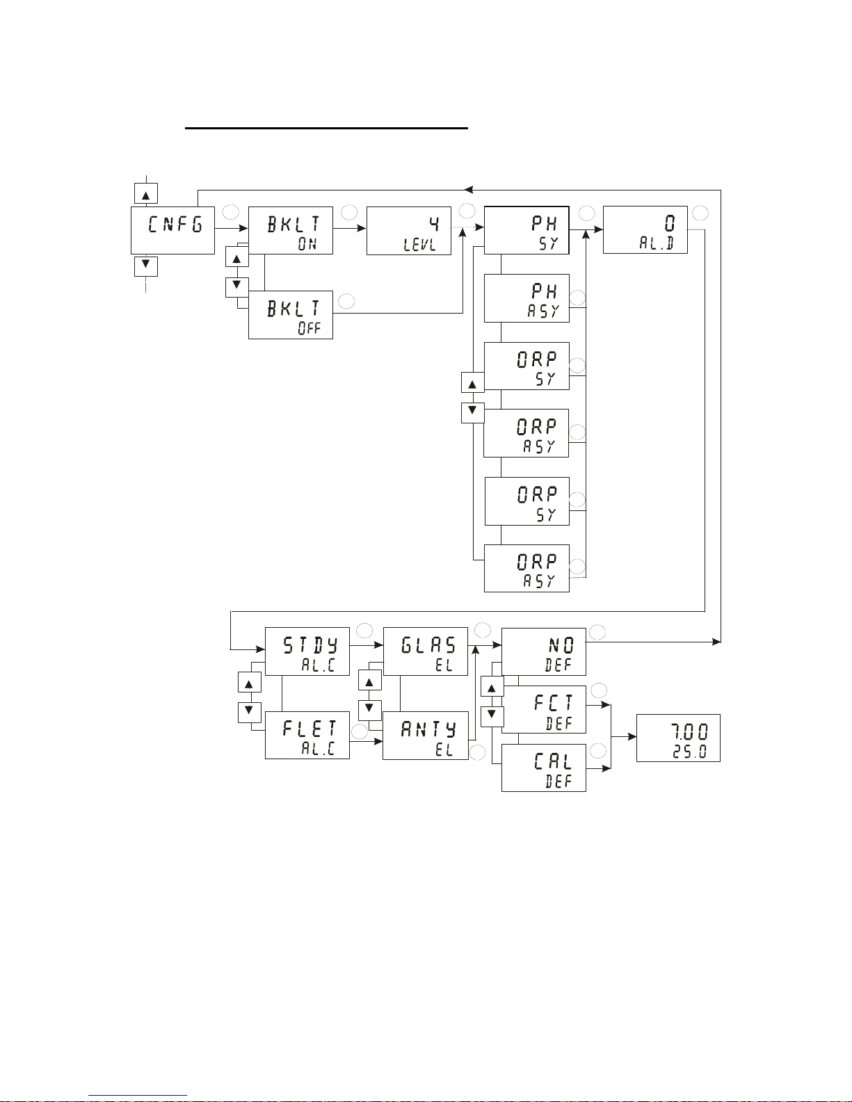
6.8 Configuration (CNFG) sub-function
In this sub-function you configure the controller to suit your requirements.
SETUP
HOLD
SETUP
HOLD
SETUP
HOLD
SETUP
HOLD
SETUP
HOLD
SETUP
HOLD
s
%
SETUP
HOLD
SETUP
HOLD
%
m
v
SETUP
HOLD
m
v
SETUP
HOLD
s
SETUP
HOLD
SETUP
HOLD
SETUP
HOLD
ENT
ENT
ENT
ENT
ENT
ENT
ENT
ENT
ENT
ENT
ENT
ENT
ENT ENT
12
2
3
SETUP
HOLD
s
4
4
4
4
4
4
5
6
7
8
SETUP
HOLD
SETUP
HOLD
SETUP
HOLD
SETUP
HOLD
MEAS
P
H
O
C
ENT
ENT
ENT
ENT
6
7
8
8
1. Select the “CNFG” sub-function, then press the ENT key.
2. Enabling/disabling the display backlight: press the ▲ or ▼ key to
switch display backlight on (BKLT ON) or off (BKLT OFF). Press the ENT
key to confirm your selection.
3. Setting the backlight intensity (appears only If backlight is on): press
the ▲ or ▼ key to set backlight intensity (setting range: minimum 1 to
maximum 4). Press the ENT key to confirm your setting.
4. Selecting the measurement mode: press the ▲ or ▼ key to select
measurement mode:
Page 38

– “PH SY” = pH measurement with symmetrical input
– “PH ASY” = pH measurement with asymmetrical input
– “ORP % SY” = ORP-% measurement with symmetrical input
– “ORP % ASY” = ORP-% measurement with asymmetrical input
– “ORP mV SY” = ORP-mV measurement with symmetrical input
– “ORP mV ASY” = ORP-mV measurement with asymmetrical input
Press the ENT key to confirm your selection.
5. Setting the alarm delay time in seconds: press the ▲ or ▼ key to set
the alarm delay time (setting range: 0 to 1999 seconds). Press the ENT
key to confirm your setting.
Note: With this parameter you set the delay before the alarm relay
activates when the set point has been exceeded.
6. Selecting the alarm contact type: press the ▲ or ▼ key to select the
alarm contact type:
– “STDY” = steady contact
– “FLET” = fleeting (single pulse) contact
Press the ENT key to confirm your selection.
Note: With this parameter you select whether the alarm contact will
operate as a steady contact or a fleeting (single pulse) contact. Pulse
contact closing time is 1 second.
7. Selecting the sensor type: press the ▲ or ▼ key to select the sensor
type which is connected to the controller:
– “GLAS” = glass electrode
– “ANTY” = antimony electrode
Press the ENT key to confirm your selection.
Note: This parameter is not available in ORP mode.
Note: After each changeover, the factory calibration data for zero point
and slope are overwritten. Be sure to recalibrate (see section 5).
Page 39

8. Resetting the controller settings to factory defaults: The display shows “NO
DEF”. Press the ▲ or ▼ key to select:
– “NO DEF” = keeps old values active, when confirmed with ENT.
– “FCT DEF” = resets all settings to factory defaults, when confirmed with
ENT.
– “CAL DEF” = resets calibration settings to factory defaults, when confirmed
with ENT.
Press the ENT key. The selected function will be executed and the controller
returns automatically to the Measurement mode.
Continue with Setup mode procedures, or return to Measurement mode by
pressing the ▲ and ▼ keys simultaneously (escape).
6.9 Calibration (CAL) sub-function
The calibration procedure in Setup mode is identical to the procedure in the
Calibration mode (see section 5). The only difference is that the transmitter
remains in Setup mode (instead of Measurement mode) after calibration is
completed.
Page 40
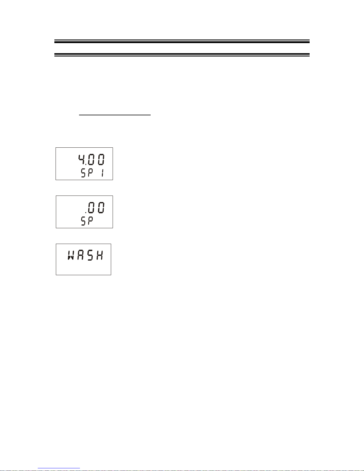
7 RELAY MODES
You can control devices connected to Relay A, Relay B or wash relay via the
front panel of the transmitter. In Automatic mode, the controller’s set point
values activate the relays. In Manual mode, you can manually turn “on” and
“off” the control devices connected to relay A or relay B.
7.1 View relay set points
To view relay setpoints, the relay mode must be set to automatic (standard
mode after switch-on, relay mode LED “Auto” lights).
While in Measurement mode press the REL key.
P
H
The display shows the set point value for Relay A and LED
“A” lights.
8
2
P
H
After two seconds the display shows the set point value for
Relay B and LED “B” lights).
off
After two seconds the display shows the status of the Wash
relay and LED “W” lights. If Wash relay is “off” the display
shows “WASH OFF”. If Wash relay is “on” the wash interval
time and wash duration is displayed
After an additional two seconds the controller will return to Measurement
mode.
Page 41
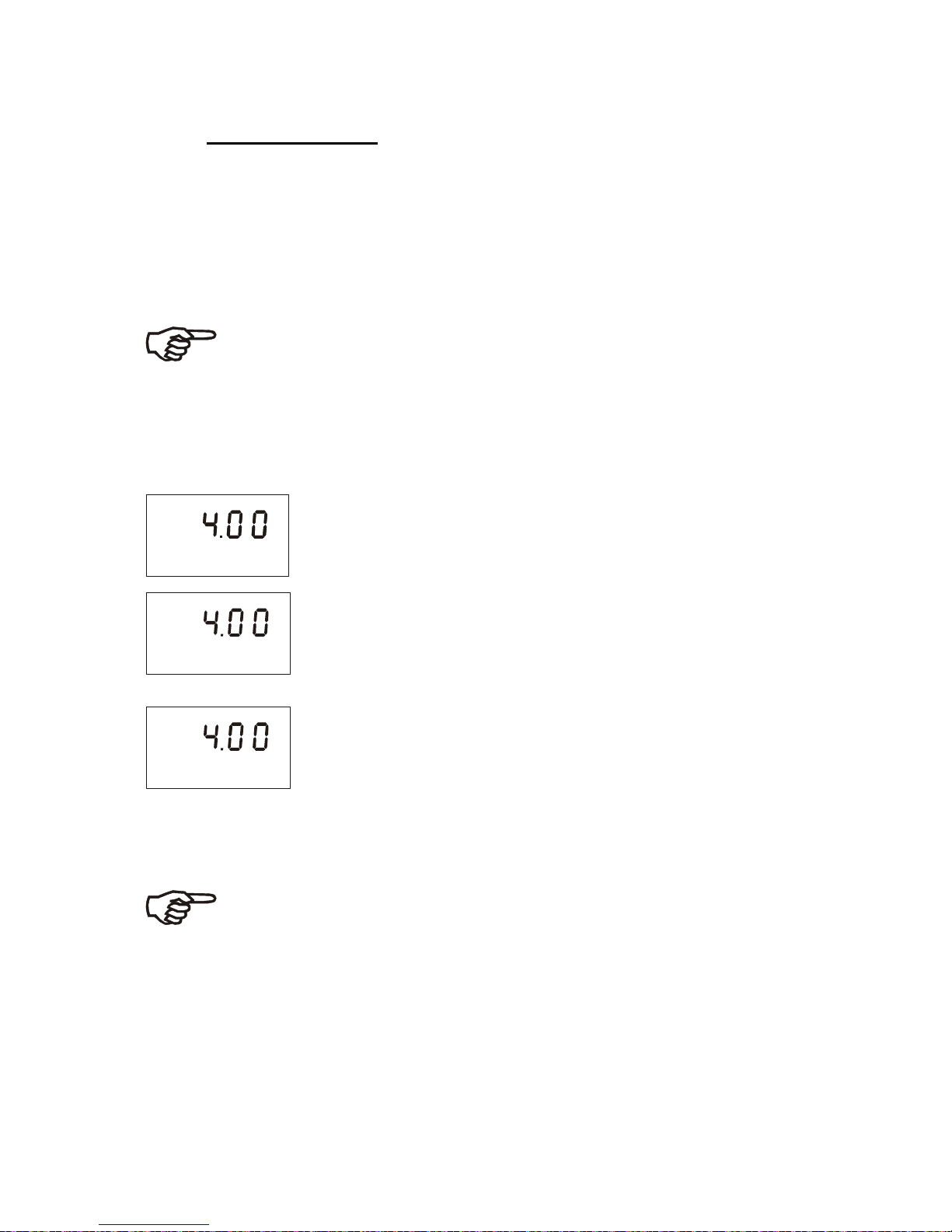
7.2 Manual relay mode
In manual relay mode, you can manually turn “on” and “off” the control
devices connected to Relay A, Relay B or Wash relay.
1. While in Measurement mode press the MODE key.
2. The display prompts you to enter the security code. Press the ▲ or ▼
key to set security code to “22”.
3. Press the ENT key. The Manual relay mode is activated and the relay
mode LED “MANU” lights.
Note: Pressing ENTER key at a value other than “22” will cause the
controller to revert to Measurement mode, and the relays will remain in
automatic mode.
4. Press the REL key to select either Relay A, Relay B or Wash relay. The
corresponding LED (A, B, or W) turns to red.
The manual control options now available depend on the control type (limit,
pulse frequency, or pulse length) you selected and set in section 6.5.
P
H
SETUP
HOLD
off
P
H
SETUP
HOLD
off
If you selected Limit control: The display shows the current
measured value and “OFF” or “ON” depending on the relay
status of the currently selected relay.
P
H
SETUP
HOLD
o
If you selected Pulse length control: The display shows the
current measured value (upper value) and the on time as a
percentage of the current duration set in the CNTR subfunction in setup mode (lower value).
P
H
SETUP
HOLD
o
If you selected Pulse frequency control: The display shows the
current measured value (upper value) and the pulse frequency
(lower value).
5. Press the ▲ or ▼ key to change the Relay on/off status, pulse length,
pulse frequency or wash function. The relay status LED at the right of the
controller will also change from Red to Green.
Note: If you wish to manually change the status of relays, press the
REL key at this point and repeat step 5 for the other two relays. The
relay(s) will remain under manual control while you are setting a relay.
6. Press the MODE key to return to Measurement mode. The relays are now
back to automatic control.
Page 42
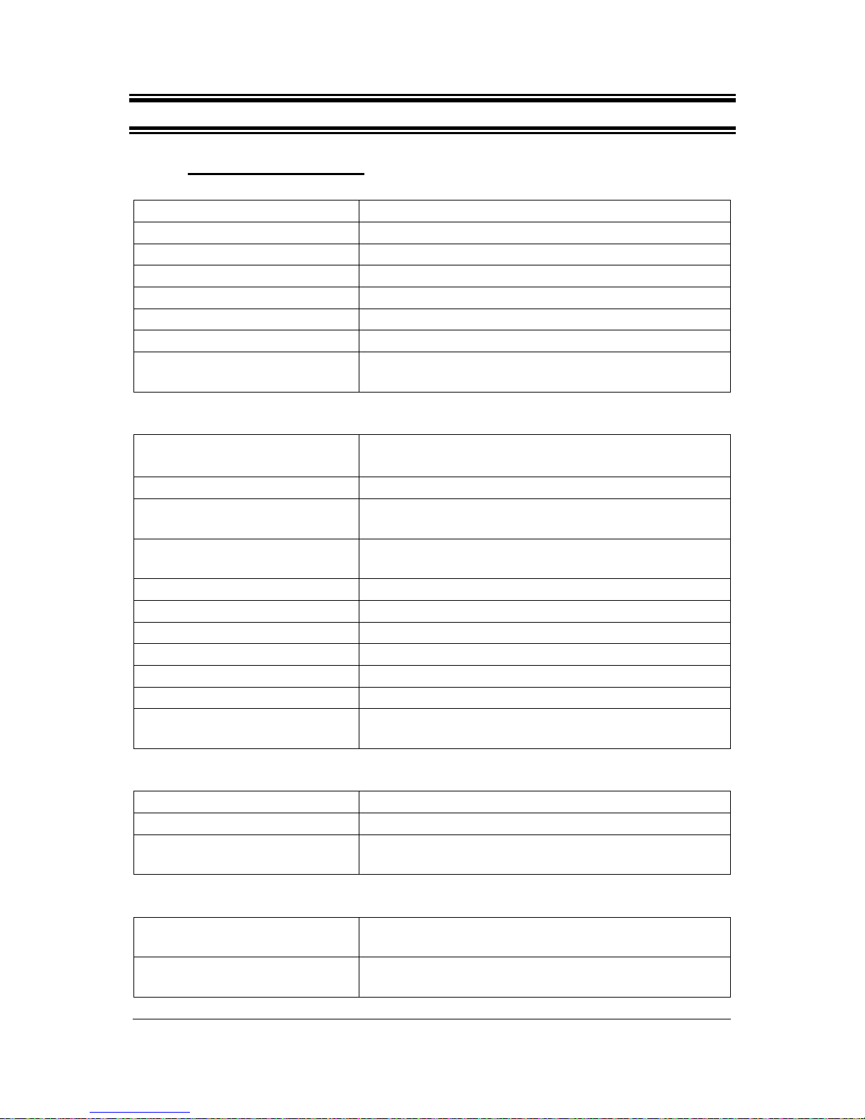
8 TECHNICAL SPECIFICATIONS
8.1 General Specification
Alpha pH 2000 Controller / Transmitter
pH Range -2.00 to 16.00 pH
Resolution & Accuracy 0.01 pH & ± 0.01 pH
mV Range 0 to 100% or -1000 to 1000 mV
Resolution & Accuracy 0.1% or 1 mV / ± 1 mV
Temperature -9.9 to 125 oC (15.0 to 257.0 oF)
Resolution & Accuracy 0.1 & ± 0.5 oC (± 1.0 oF)
Sensor Pt 1000 or Pt 100 (jumper selectable)
Temperature Compensation Automatic (± 10 oC / ± 18 oF offset adjustment) /
Manual
Set-point And Controller Functions
Function Limit / Proportional Control / Proportional Integral
(Pulse Length or Pulse Frequency)
Integral time 0 to 999.9 minutes
Adjustable period with pulse
length controller
0.5 to 20 sec
Adjustable period with pulse
frequency controller
60 to 120 pulses/min
Pickup / Dropout Delay 0 to 1999 seconds
Wash Cycle 0.1 to 199.9 hours
Wash Duration 1 to 1999 seconds
Switching pH Hysteresis 0.1 to 1 pH
Switching ORP Hysteresis 1 to 10.0 % / 10 to 100 mV
Contact Outputs, Controller 1 SPDT; 3 SPST relays
Switching
Voltage/Current/Power
Max 250 VAC / Max 3A / Max 600 VA
Alarm Functions
Function (switchable) Latching / pulse
Pickup delay 0 to 1999 seconds
Switching
Voltage/Current/Power
Max 250 VAC / Max 3A / Max 600 VA
Display
LCD UV coat, backlit 14 segments display with symbols
for status information
Backlight On/Off selection with four level of brightness
control
Page 43

EMC Specifications
Emitted Interference EN 61 326
Immunity to Interference EN 61 326
Environmental Conditions
Ambient Temp. Operating
Range
-10 to 50 oC (14 to 122 oF)
Rel. Humidity 10 to 95% (non-condensing)
Power Supply
Input 80 to 250 VAC/DC 48/62 Hz
Main Fuse 250 mA anti-surge
Pollution Degree 2
Transient Overvoltage category II
8.2 Specifications for wall mount version
Electrical Data and
Connections
Signal output Two 0/4 to 20 mA outputs for pH/mv and
temperature , galvanically isolated
Load Max.600 Ω
pH / ORP Input BNC (1012 Impedance)
Connection terminal (1 x 3-pins; 8-pin, 9-pin & 13-pin terminal blocks)
Mechanical Specification
Dimensions
144 x 144 x 111.5 mm (5.67 x 5.67 x 4.39 inch)
Weight 745g (unit); 1100g (boxed)
Material PBT
Insulation NEMA 4X, IP 65
Page 44
8.3 Specifications for panel mount version
Electrical Data And Connections
Signal output Two 0/4 to 20 mA outputs for pH/mv and
temperature , galvanically isolated
Load Max.600 Ω
pH / ORP Input BNC (1012 Impedance)
Connection terminal (1 x 3-pin; 1 x 9-pin & 1 x 19-pin terminal
blocks)
Mechanical
Specifications
Dimensions 175 x 96 x 96 mm ( 6.89 x 3.78 x3.78 inch)
Weight 550g (unit); 950g (boxed)
Material ABS
Insulation IP 54 (front) , IP 40 (housing)
Page 45
9 ACCESSORIES
9.1 Replacement Unit
Product Description Thermo Scientific
Order Code
Alpha pH 2000 pH/ORP Controller/Transmitter, wall mount
version
TSPHCTP2000W
Alpha pH 2000 pH/ORP Controller/Transmitter, panel
mount version
TSPHCTP2000P
Product Description Eutech Instruments
Order Code
Alpha pH 2000 pH/ORP Controller/Transmitter, wall mount
version
ECPHCTP2000W
Alpha pH 2000 pH/ORP Controller/Transmitter, panel
mount version
ECPHCTP2000P
9.2 Assembly Accessories
Product Description Eutech Instruments
Order Code
pH Combination Electrode with Pt 100 RTD and PMP EC100GTSO05B
pH Combination Electrode with HF resistant glass
(w/o ATC & PMP)
ECARTSOHF05B
pH Combination Electrode with PMP (w/o ATC) ECARGTSO05B
pH Combination Electrode with high temperature
resistance (110
o
C) and high pressure resistance (9
bar) (w/o ATC & PMP)
ECARHTTSO05B
pH Combination Electrode (w/o ATC & PMP) ECARTSO05B
ORP Gold Electrode with PMP but w/o ATC ECHTAUTSO05B
ORP Platinum Electrode with PMP but w/o ATC ECHTPTTSO05B
Note: Above pH/ORP electrodes withstand up to 6 bar pressure except ECARHTTSO-05B. These electrodes have integral 5m measuring cable terminating with
a BNC connector.
Please contact your authorised distributor or dealer for the prices of extension
measuring cables and other accessories like tee joints, electrode assembly, and
calibration solutions.
Page 46

10 GENERAL INFORMATION
10.1 Warranty
This Controller transmitter is supplied with a one-year warranty against significant
deviations in material and workmanship from date of purchase and a six-month
warranty for probe. Each instrument will have a warranty card with a specific serial
number. The warranty card must be endorsed by the Authorized Distributor at the
point of sale.
If repair or adjustment is necessary and has not been the result of abuse or misuse
within the designated period, please return – freight pre-paid – and correction will be
made without charge. Thermo Scientific/ Eutech will determine if the product
problem is due to deviations or customer misuse.
Out of warranty products will be repaired on a charged basis.
Exclusions
The warranty on your instrument shall not apply to defects resulting from:
• Improper or inadequate maintenance by customer
• Unauthorized modification or misuse
• Operation outside of the environment specifications of the products
10.2 Packaging
The instrument is packaged in a corrugated box with a warranty card, instruction
manual and the following accessories:
Wall mount version
• Plug, nylon, black, 2 pcs
• PG 13.5, cable gland, 3 pcs
• Connectors, 1 each of 3-way (5.08 mm), 9-way(5.08 mm), 13-way (3.5 mm), 8-
way (3.5 mm)
Panel mount version
• Rubber Gasket, 1 pc
• Catch, 2 pcs
• Rod, thread, 2 pcs
• Connectors, 1 each of 3-way (5.08 mm), 9-way (5.08 mm) and 19-way (3.5 mm).
10.3 Return of Goods
Authorization must be obtained from our Customer Service Department or
authorized distributor before returning items for any reason. A “Return Goods
Authorization” (RGA) form is available through our authorized distributor. Please
include data regarding the reason the items are to be returned. For your protection,
items must be carefully packed to prevent damage in shipment and insured against
possible damage or loss. Thermo Scientific will not be responsible for damage
resulting from careless or insufficient packing. A restocking charge will be made on
all unauthorized returns.
NOTE: Thermo Scientific reserves the right to make improvements in design,
construction, and appearance of products without notice.
Page 47

10.4 Guidelines for Returning Unit for Repair
Use the original packaging material if possible when shipping the unit for repair.
Otherwise wrap it with bubble pack and use a corrugated box for additional
protection. Include a brief description of any faults suspected for the convenience of
Customer Service Dept., if possible.
10.5 Maintenance and Cleaning
Maintenance
The Alpha pH 2000 contains no user repairable components. Please contact Eutech
Instruments or its distributor if there is any problem with the unit.
Cleaning
To remove dust, dirt and spots, the external surfaces of the controller may be wiped
with a damp, lint-free cloth. A mild household cleaner can also be used if necessary.
Page 48
11 APPENDICES
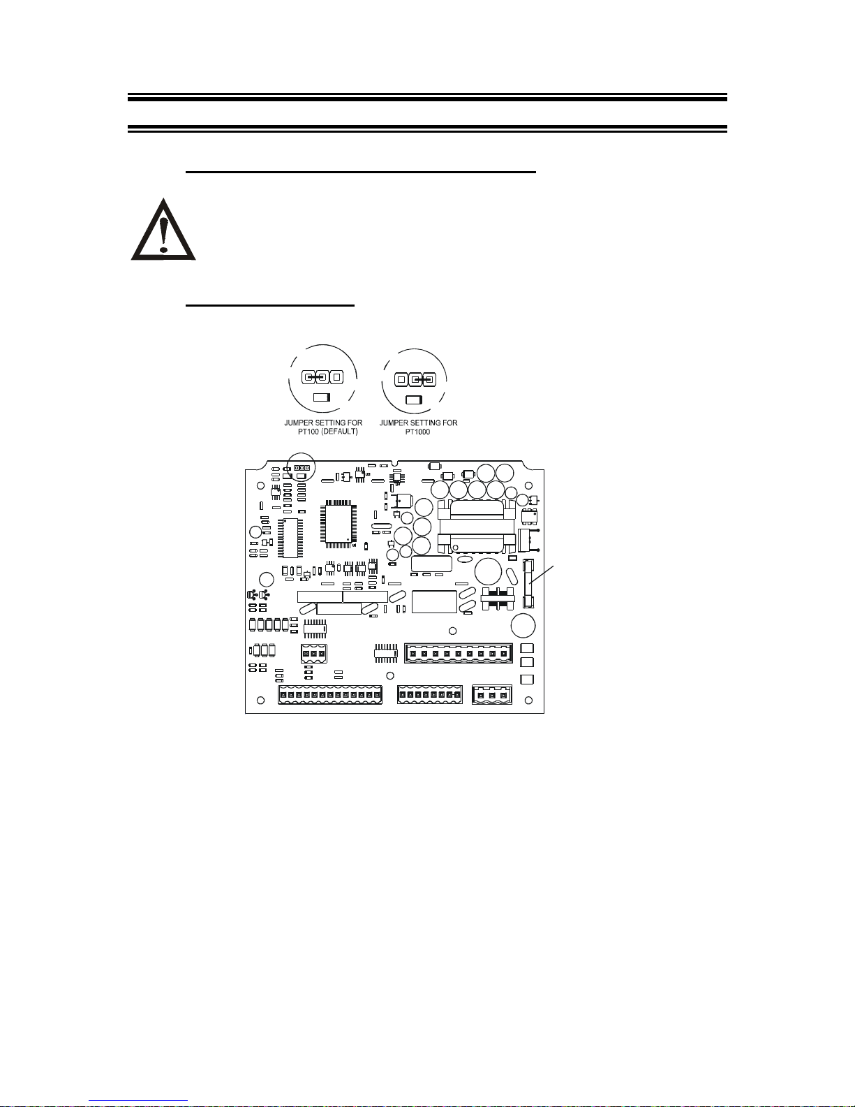
11.1 Appendix 1 – Unit fuse and jumper settings
− Caution! Before opening the unit to replace the unit fuse or to set the
jumper for Pt 100 / Pt 1000 temperature sensor, make sure the mains
cable is separated from the power supply.
Wall mounting version
+
2
2
0
K
L10
C64 C61
C63
C65
C62
R76
C60
2
2
0
K
C115
C112
C114
R104
R105
L5
C80
C76
C79
J7
J6 J5
2
2
0
K
2
2
0
K
C71
J1
L6 L7
U6
L9
BR1
U5
2
2
0
K
2
2
0
K
2
2
0
K
2
2
0
K
L5 L4 L2 L1 L3
C44
C
4
3
C
4
5
C53
C54
C
5
5
C
5
2
TS9
TS11
K1 K2
C123
R34 R34C122
Q6
Q10
+
+
R8
R9
C8
R7 C12
C10 C9
Z1
REG5
C109
REG4
REG3
REG2
R83
R85
R84
C
7
5
R102
R
1
0
3
C110
C99
C
1
1
1
U2
Q15
TS8
F1
L13
TS13
K4
T
S
1
2
R92
C81
1003
R28
U13
C120
Z4
+
C82
+
+
+
+
+
+
+
C95
C88
C86
C87
C85
C90
C89
C84
R101
R100
C106
D11
D12
D13
C105
+
+
+
+
+
+
D15
C104
C93
C100
T1
C94
+
C92
C91
C103
C107
C2
C1
X1
D14
R
1
0
C102
C101
R1
REG1
R2
C7
R12
C6
R11
C11
R32
C21
108
+
C21
R32
R36
U7
R24 C16
Q2
R23
R33
C25
R37
C24
C29
C27
C28
R
3
1
R
3
5
C
2
2
C
2
6
R38
C23
C15
R4
R3
R5
R6
D1
C28
C28
Fuse: 250V,
250mA,
Antisurge
Page 49
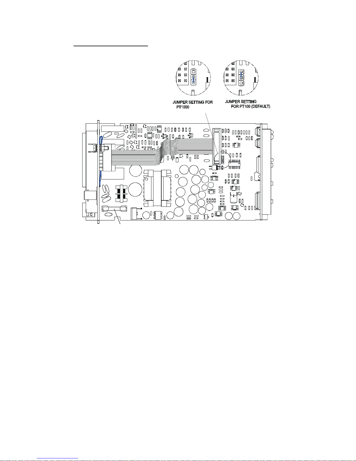
Panel mounting version
J4 J4
R
4
4
C
5
5
C
5
9
REG5
REG1
C69
C
6
6
C
6
8
R49
R48
R46
D10
C
7
3
R
4
5
REG7
C
1
0
7
C
1
2
4
C
1
2
5
R
1
0
7
C
1
2
3
U8
R94
C
1
0
4
C
9
1
C
9
2
C
8
5
C
8
9
C
8
8
R
7
7
C
9
0
Q
1
1
Q10
C86
C84
R79
C87
C102
C97
Z3
T
S
7
T
S
8
Q15
C
1
1
2
R
9
5
C
1
1
1
R
9
9
R
1
0
4
C122
R
1
0
5
R101
C110
C115
R100
C109
C
1
0
8
C
1
2
1
C
1
1
9
U9
R
9
8
C113R96
C114
J25
R
1
0
2
R
1
0
3
C
1
2
0
C
1
1
6
R
9
7
C117
C
1
1
8
J4
TS13
F1
TS1
C28
Fuse: 250V ,
250mA,
Antisurge
U6
C57
C40
J3
TS13
C
3
4
+
R39
REG2
+
R43
C49
Q3
+
R41
R40
C38
Z2
+
+
C48
R42
C39
+
C53
C36
C37
+
REG4
C54
+
D11
C58
T
1
R74
C28
C29 C30
L1
+
C31
TS5
K5
+
BR1
J11
R
7
2
R
6
9
R
6
7
R
6
6
C76
D12
D13
R57
K2
C77
TS2
K1
C75
R53
R75
R76R62R59R60
R56
Q6
C80
Q7
D
1
5
D14
R65
R82
R81
C
8
3
R58
C78
R55
R54
Q5
R55 R5 1
Q
5
0
1
R78
R71
Q9
R70
C74
Q4
R50
Q8
R
1
0
6
T
S
1
1
C41
+
C42
+
C44
+
C43
+
+
C62
C
5
2
C
5
1
C
5
0
C
5
6
+
C45
+
+
REG6
C65
C70
C106
+
+
C46
Q14
C35
Z12
C96
+
+
+
C67
C47
+
Q16
C71
REG8
C72
TS12
R93
C
1
0
3
C
1
0
5
8
4
X
2
7
7
4
0
1
M
A
I
N
A
L
P
H
A
p
H
1
1
0
0
R
E
V
0
.
3
C
6
0
REG3
R47
C64
C61
C63
Page 50

11.2 Appendix 2 – pH buffer values at various temperatures
The following table shows the various pH values at different temperature of
the solution during calibration.
Tempera
ture (oC)
pH 1.00 pH 4.01 pH 6.86 pH 7.00 pH 9.00 pH 9.18 pH 10.01
0 0.96 4.01 6.98 7.12 9.33 9.47 10.32
5 0.99 4.01 6.95 7.09 9.24 9.38 10.25
10 0.99 4.00 6.92 7.06 9.16 9.32 10.18
15 0.99 4.00 6.90 7.04 9.11 9.27 10.12
20 1.00 4.00 6.88 7.02 9.05 9.22 10.06
25 1.01 4.01 6.86 7.00 9.00 9.18 10.01
30 1.01 4.01 6.85 6.99 8.95 9.14 9.97
35 1.01 4.02 6.84 6.98 8.91 9.10 9.93
40 1.01 4.03 6.84 6.97 8.88 9.07 9.89
45 1.01 4.04 6.83 6.97 8.85 9.04 9.86
50 1.01 4.06 6.83 6.97 8.82 9.01 9.83
55 1.01 4.08 6.83 6.97 8.79 8.99 9.81
60 1.02 4.10 6.84 6.98 8.76 8.96 9.79
70 1.02 4.12 6.85 6.99 8.72 8.92 9.76
80 1.02 4.16 6.86 7.00 8.68 8.89 9.74
90 1.02 4.20 6.88 7.02 8.65 8.85 9.73
Page 51
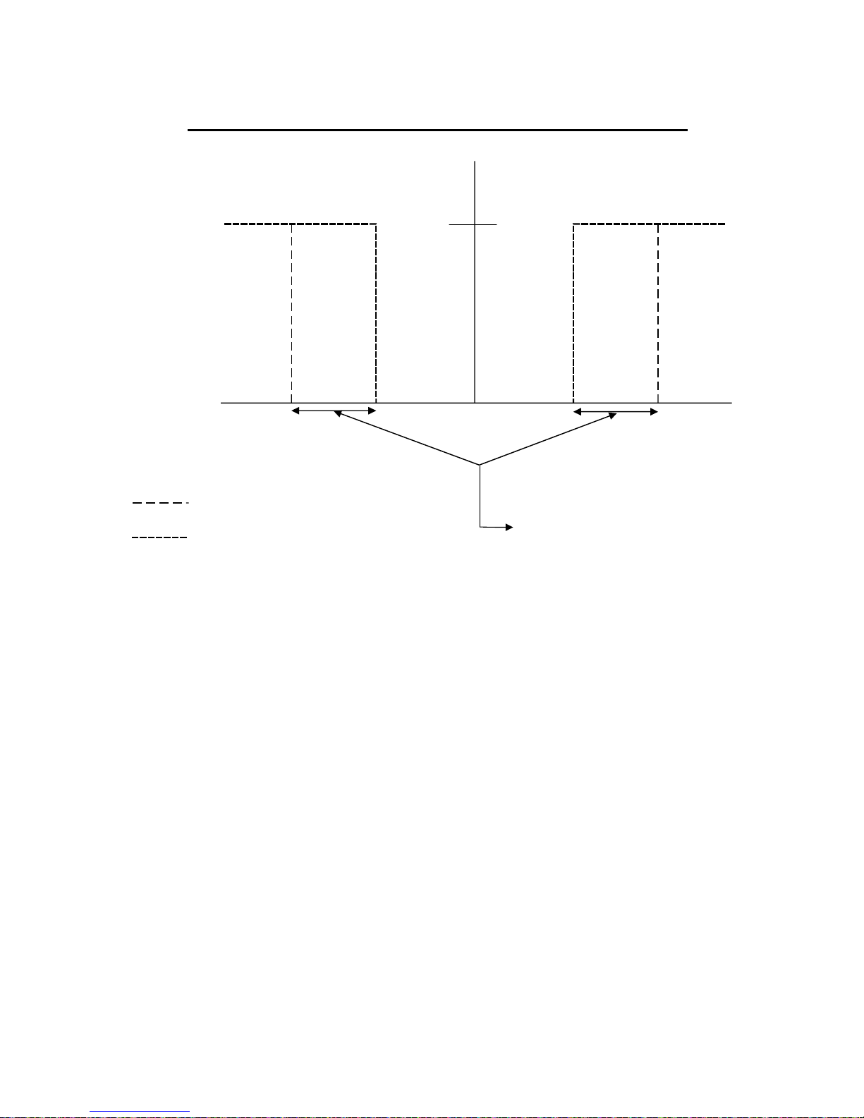
11.3 Appendix 3 –Simple explanation on the function of hysterisis
4 . 0 4.5 9.5 1 0 . 0
7.0
R E L A Y O F F
H Y S T E R E S I S B A N D
( D E F A U L T = 0 . 5 p H )
F O R W A R D D I R E C T I O N
R E V E R S E D I R E C T I O N
S P 1
S P 2
R E L A Y O N
S P 1 S e t t o L O
S P 2 S e t t o H I
The controller relay activates when the set-point is reached. In the reverse
direction, it does not de-activate when the value reaches the set-point.
Instead, it continues to be active till the value reaches the amount set by the
Hysteresis band.
Page 52
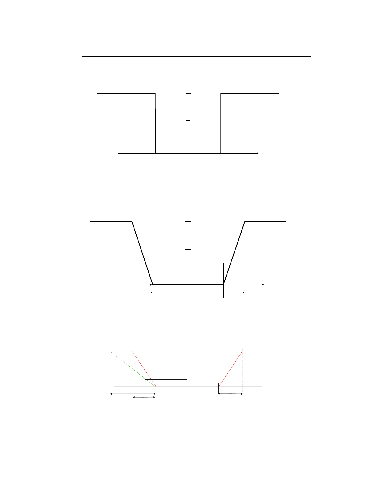
11.4 Appendix 4 – General instructions concerning Controller Setting
11.4.1 Control characteristic of Controllers used as limit value switch
MIN Function
MAX Function
X
p
=0
Xp =0
SP 1
SP 2
+Xw
-Xw
Yh
0%
50 %
100 %
11.4.2 Control characteristic of P-Controller as proportional controller
MIN Function
MAXFunction
Xp
Prop. Band
Xp
Prop. Band
SP 1
S
P2
+Xw
-Xw
Yh
0%
50 %
100 %
11.4.3 Control characteristic of PI-Controller as a proportional integral
controller
SP1 SP 2
10%
Proportiona l. band
X
P
Prop. band
X
P
20%
25%
100%
50%
Page 53
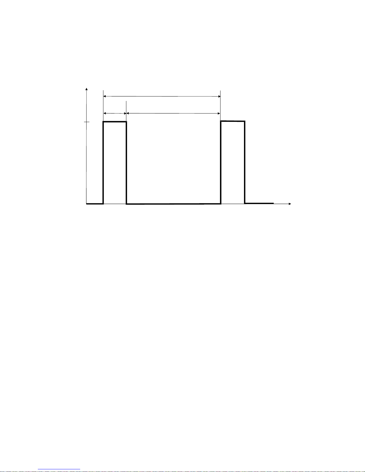
11.4.4 Controller signal of Pulse length Controllers
t
ON
t
OFF
Pulse Length T
Relay
ON
OFF
Time [s]
The output relay of the pulse length controller is clock-timed. The switching
period T remains constant. Depending on the divergence from the limit
value, the switch-on time tON is increased or decreased in accordance with
the proportional range Xp.
The following applies:
t
ON
+ t
OFF
= T (Const.)
greater divergence Î greater tON
Xp exceeded Î t
ON
= T (relay remains picked up)
Page 54

11.4.5 Controller signal of Pulse Frequency Controllers
t
ON
t
OFF
Pulse Length T
Relay
ON
OFF
Time [s]
The output relay of the pulse frequency controller is clock-timed. The pulse
duration tON remains constant at 250mS. Depending on the divergence from
the limit value, the frequency (1/T) is increased or decreased in accordance
with the proportional range Xp.
The following applies:
tON = Const. (250 msec.)
greater divergence Î greater f (greater frequency)
Xp exceeded Î max. frequency
Page 55

11.5 Appendix 5 – Abbreviations used in menu displays
Abbreviation Meaning Abbreviation Meaning
MEAS Measurement CUR.1 Output current 1
CAL Calibration CUR.2 Output current 2
ENT Enter OUT Output signal
OFS Offset 4 - 20 4 to 20mA
C.CD Calibration Security Code 0 - 20 0 to 20 mA
S.CD Setup Security Code R.0 Value at 0 mA
SET Setting R. 4 Value at 4 mA
ATC Automatic Temperature
Compensation
R. 20 Value at 20 mA
SP1 Setpoint 1 CU22 Out of range output
current 22 mA
SP2 Setpoint 2 WASH Wash
LO Low limit H. INT Cleaning interval in hours
HI Hi Limit S. DUR Cleaning duration in
seconds
HYS Hysteresis CONF Configuration
ON.D On delay BKLT Back light
OFF.D Off delay LEVL Level
CNTR Controller PH SY Symmetrical pH mode
L.Ct Limit control PH ASY Asymmetrical pH mode
PLC Pulse Length Control ORP SY Symmetrical ORP mode
PFC Pulse Frequency Control ORP ASY Asymmetrical ORP mode
P/PI Proportional control AL. D Alarm delay
EN Energized AL.C Alarm Contact
DEEN Deenergized STDY Steady
REL Relay FLET Fleet, impulse
PRP Proportional band GLAS EL Glass electrode
T.PL Pulse length time ANTY EL Antimony electrode
F.PF Pulse frequency time DEF Default
IAT Integral action time FCT DEF Factory default
MANU Manual CAL DEF Calibration default
Page 56

Water Analysis Instruments
North America
166 Cummings Center
Beverly, MA 01915 USA
Toll Free: 1-800-225-1480
Tel: 1-978-232-6000
Dom. Fax: 1-978-232-6015
Int’l Fax: 978-232-6031
Europe
P.O. Box 254, 3860 AG Nijkerk
Wallerstraat 125K, 3862 CN Nijkerk,
Netherlands
Tel: (31) 033-2463887
Fax: (31) 033-2460832
Asia Pacific
Blk 55, Ayer Rajah Crescent
#04-16/24, Singapore 139949
Tel: 65-6778-6876
Fax: 65-6773-0836
www.thermo.com/process
© 2009 Thermo Fisher Scientific Inc.
All rights reserved. Thermo Fisher Scientific Inc.
68X216830 Rev 4
 Loading...