

Page 1
Analyze •Detect•Measure •Control
™
Orion 94-16
Orion 96-16 ionplus
Orion Silver/Sulfide
Electrode
INSTRUCTION MANUAL
Ag
/S
+
-
2
Page 2

AQUAfast, Cahn, EZ Flash, Ionalyzer, ionplus, KNIpHE, No Cal, ORION, perpHect,
PerpHecT, PerpHecTion, pHISA, pHix, pHuture, Pure Water, Sage, Sensing the
Future, SensorLink, ROSS Ultra, Sure-Flow, TEA Analyzer, Titrator PLUS, TURBO2
and Wine Master are registered trademarks of Thermo Electron Corporation.
1-888-pHAX-ION, A+, All in One, Aplus, AQUAsnap, AssuredAccuracy,
AUTO-BAR, AUTO-CAL, AUTO DISPENSER, Auto-ID, AUTO-LOG, AUTO-READ,
AUTO-STIR, Auto-Test, BOD AutoEZ, Cable-Free, CERTI-CAL, CISA, DataCOLLECT,
DataPLUS, digital LogR, DirectCal, DuraProbe, Environmental Product Authority,
Extra Easy/Extra Value, FAST QC, Flash Titration, Flash Titrator, GAP, GLPcal,
GLPcheck, GLPdoc, ISEasy, KAP, LabConnect, LogR, Low Maintenance Triode,
Minimum Stir Requirement, MSR, NISS, One-Touch, One-Touch Calibration, OneTouch Measurement, Optimum Results, Pentrode, pHuture MMS, pHuture
Pentrode, pHuture Quatrode, pHuture Triode, Quatrode, QuiKcheK, rf link,
ROSS, ROSS Resolution, SAOB, Smart CheK, Stacked, Stat Face, The Enhanced
Lab, ThermaSense, Triode, TRIUMpH, Unbreakable pH, Universal Access are
trademarks of Thermo.
Guaranteed Success and The Technical Edge are service marks of Thermo.
PerpHecT meters are protected by U.S. patent 6,168,707.
PerpHecT ROSS are protected by U.S. patent 6,168,707.
ORION Series A meters and 900A printer are protected by U.S. patents
5,108,578, 5,198,093 and German patents D334,208 and D346,753.
Sure-Flow electrodes are protected by European Patent 278,979
and Canadian Patent 1,286,720.
ionplus electrodes and Optimum Results solutions are protected by
US Patent 5,830,338.
ROSS Ultra electrodes have patents pending.
ORION ORP Standard is protected by US Patent 6,350,367.
ORION Series A conductivity meters are protected by US Patent 5,872,454.
© Copyright 2003, Thermo Electron Corporation. All rights reserved. Question
everything, and Analyze.Detect.Measure.Control are trademarks of Thermo
Electron Corporation.
The specifications, descriptions, drawings, ordering information and part
numbers within this document are subject to change without notice.
This publication supersedes all previous publications on this subject.
Page 3

TABLE OF CONTENTS
General Information 1
Introduction 1
Required Equipment 2
Required Solutions 3
Before Using The Electrode 6
Electrode Preparation 6
Checking Electrode Operation (Slope) 9
Helpful Information 10
Units of Measurement 10
Sample Requirements 10
GLP Measuring Hints 11
Choosing the Right Measuring Technique 13
Silver Measurement Procedures 15
Direct Measurement 16
Low-Level Measurements 19
Known Addition 23
Low-Level Chloride Titration 30
Low-Level Cyanide Indicator Method 32
Sulfide Measurement Procedures 36
Direct Measurement 36
Analate Subtraction Measurements 40
Sulfide Titration 44
Electrode Storage 46
Electrode Maintenance 47
Troubleshooting 49
Troubleshooting Checklist 49
Troubleshooting Guide 53
Electrode Characteristics 56
Electrode Response 56
Reproducibility 56
Temperature Effects 57
Interferences 58
pH Effects 59
Complexation 59
Theory of Operation 60
Warranty 62
Ordering Information 66
Specifications 67
Page 4

Page 5

GENERAL INFORMATION
Introduction
The Orion 94-16 Silver/Sulfide Half-Cell Electrode and Orion 96-16
Sure-Flow
™
Combination Silver/Sulfide Electrode measure silver and
sulfide ions in aqueous solutions quickly, simply, accurately, and
economically. Because of the extreme insolubility of silver sulfide,
the two ions are virtually never present in solution together. This
electrode also performs low-level cyanide and halide titrations.
The Orion 96-16 offers additional benefits from the Sure-Flow
Combination reference design. With this electrode, a separate
reference electrode is unnecessary, making it convenient to use with
small sample volumes. The free-flowing liquid junction assures
stable, drift-free potentials. When measuring dirty samples which
would clog conventional electrode junctions, the Sure-Flow junction
can be opened and flushed clean simply by pressing the cap. The
Orion 900200 Double Junction Reference electrode, when used with
the 9416 Silver/Sulfide Half-Cell Electrode, also offers the benefits
of the Sure-Flow junction design.
General analytical procedures, required solutions, electrode
characteristics, and electrode theory are discussed in this manual.
Operator instructions for Orion meters are given in the meter
instruction manual.
Thermo Electron Corporation’s The Technical Edge for Customer
Service and Support for Orion Products can be consulted for
assistance and troubleshooting advice. Please refer to
Troubleshooting for information on contacting Thermo Electron.
1
Page 6

Required Equipment
Meter – The easiest to use are direct concentration readout specific
ion meters (ISE meters), such as Orion EA 940, 920A, 720A, 710A,
or 290A. If unavailable, a pH/mV meter with readability to 0.1 mV,
such as Orion 420A, 520A, or 525A is recommended.
Reference Electrode Orion
For use with Orion 94-16:
Orion 90-02 Double Junction 900200
Reference Electrode, includes:
Inner Chamber Filling Solution 900002
Outer Chamber Filling Solution 900003
For use with Orion 96-16:
The 96-16 Combination n/a
Silver/Sulfide Electrode does
not require a separate reference electrode.
Magnetic Stirrer, Stir Bars – Recommended for
laboratory measurements.
Graph Paper – 4 cycle semi-logarithmic paper for preparing
calibration curves (for use with pH/mV laboratory meters).
Plastic Labware – For low-level silver measurements.
Polishing Strips – Orion 948201. To clean the silver/sulfide
sensing element.
2
Page 7

Required Solutions
Distilled or Deionized Water – To prepare all solutions and
standards. Water to prepare sulfide standards should also
be deaerated.
Reference Filling Solution Orion
Optimum Results
™
B 900062
(for 96-16 Combination
Silver/Sulfide Electrode)
Inner Chamber Filling Solution 900002
(for use with 90-02
Reference Electrode)
Outer Chamber Filling Solution 900003
(for use with 90-02
Reference Electrode)
Silver Solutions Orion
Standard solution Customer
0.1 M or 1000 ppm as silver Prepared
(see below)
Low-level Chloride Titrant Customer
2.82 x 10
-3
M AgNO
3
Prepared
(see below)
Ionic Strength Adjustor (ISA): 940011
To adjust ionic strength of samples
and standards, 5M NaNO
3
Sulfide Solutions Orion
Sulfide Anti-Oxidant 941609
Buffer (SAOB ll) Reagent Pack
Lead Perchlorate Solution (0.1M) 948206
For titration of sulfide standard solutions
Sulfide Standard: Customer
100 ppm as S
2-
Prepared
(see below)
3
Page 8

Customer Prepared Solutions
Silver Stock Standard Solutions
Required Chemicals:
Silver Nitrate, Reagent Grade, pulverized and dried in oven at
150 °C for one hour.
Distilled Water
Preparation:
0.1 M AgNO
3
solution:
dry pulverized, reagent grade silver nitrate at 150 °C for one
hour. In a 1-liter flask, place 16.99 g of the dried silver nitrate.
Dissolve the solid, and dilute to volume with distilled water.
Store in an opaque bottle in a dark place.
1000 ppm silver solution:
weigh out 1.57 g of reagent grade silver nitrate, dried as above,
in a 1-liter volumetric flask. Dissolve and dilute to volume with
distilled water. Store in an opaque bottle in a dark place.
Low-level Chloride Titrant:
2.82 x 10
-3
M AgNO3(equivalent to 100 ppm chloride).
For titrations of low-level chloride. Dry reagent grade silver
nitrate as directed above. Place 0.479 g dried silver nitrate in
a 1 liter volumetric flask. Dissolve and dilute to volume with
distilled water. Store in an opaque bottle.
4
Page 9

Customer Prepared Solutions
Sulfide Standard Solutions
Required Chemicals:
Sodium Sulfide, reagent grade SAOB II, Orion 941609 Lead
Perchlorate, Orion 948206 Distilled, deaerated water.
NOTE: Water must be deaerated to prevent oxidation
of sulfide.
Preparation:
Prepare a stock solution of saturated sodium sulfide by
dissolving approximately 100 g of reagent-grade Na
2
S•9H2O in
100 mL distilled, deaerated water. Shake well and let stand
overnight. Store in a tightly stoppered bottle in a hood.
Prepare a sulfide standard weekly by pipetting 10 mL of the stock
solution into a l liter volumetric flask. Add 500 mL SAOB II and
dilute to volume with distilled, deaerated water. Determine the exact
concentration, C, by titrating 10 mL of the standard with 0.1 M
lead perchlorate, using the electrode(s) as the end point indicator,
and calculate:
C= 3206 (V
t/Vs
)
where:
C= concentration as ppm sulfide
Vt = volume of titrant at end point
Vs = volume of standard (10 mL)
Prepare other standards daily by serial dilution of the weekly
standard. To do a ten-fold dilution, pipet 10 mL of the standard into
a 100 mL volumetric flask, add 45 mL SAOB II and dilute to volume
with distilled, deaerated water.
5
Page 10

6
BEFORE USING THE ELECTRODE
Electrode Preparation
Orion 94-16 – Silver/Sulfide Half-Cell Electrode
Remove the rubber cap covering the electrode tip.
Orion 9002 – Double Junction Reference Electrode
Fill this reference electrode according to the instructions in the
reference electrode instruction manual. Fill the inner chamber with
Orion 900002 Filling Solution. Fill the outer chamber with Orion
900003 Filling Solution.
Add filling solution each day before using the electrode. The filling
solution level should be at least one inch above the level of sample
in the beaker to ensure a proper flow rate. If the filling solution is
less than one inch above the sample solution level, electrode
potentials may be erratic.
Orion 96-16 – Sure-Flow Combination
Silver/Sulfide Electrode
Orion offers a line of filling solutions designed specifically for your
application. Chose the Optimum Results
™
filling solution specially
formulated for your measuring requirements. See Temperature
Effects for a discussion on the benefits of Optimum Results
solutions. See Table 1.
Optimum Results B (Orion 900062) supplied with this electrode is
designed to minimize junction potentials and silver/sulfide ion
contamination of the sample and can be used for most silver/sulfide
measurements.
Optimum Results C (Orion 900067) is recommended for precise
silver measurements, providing optimum temperature and time
response.
Optimum Results A (Orion 900061) is recommended when precise
sulfide measurements, providing optimum temperature and time
response.
Page 11

7
Table 1
Choosing the correct filling solution for 96-16
Sure-Flow Combination Silver/Sulfide Electrode
Description Orion Purpose
Optimum
Results A 900061 Sulfide measurements
Variable sample
temperatures
Optimum
Results B 900062 Titration
Measurement of both
Ag
+
and S
2-
Constant sample
temperature
Low-level silver
measurement
Cyanide indicator method
Optimum
Results C 900067 Silver measurements
Variable sample
temperatures
Page 12

8
The 96-16 Silver/Sulfide Sure-Flow Combination Electrode is
shipped without filling solution in the reference chamber. To fill
from the flip-spout bottle:
1. Lift the spout to a vertical position.
2. Insert the spout into the fill hole in the outer sleeve and add a
small amount of filling solution to the chamber. Tip the electrode
to moisten the O-ring at the top and return electrode to a
vertical position.
3. Holding the electrode by the barrel with one hand, use the thumb
to push down on the electrode cap, allowing a few drops of
filling solution to drain and wet the inner cone.
4. Release sleeve. If sleeve does not return to its original position
immediately, check to see if the O-ring is moist enough and
repeat steps 2 - 4 until the sleeve has returned to original
position. Add filling solution up to the fill hole.
Page 13

9
Checking Electrode Operation (Slope)
This procedure measures electrode slope. Slope is defined as the
change in millivolts observed with every ten-fold change in
concentration. Obtaining the slope value provides the best means
for checking electrode performance.
These are general instructions that can be used with most meters to
check electrode operation. See individual meter instruction manuals
for more specific information.
1. If electrode(s) have been stored dry, prepare the electrode(s) as
described in Electrode Preparation.
2. Connect the electrode(s) to the meter as described in the meter
instruction manual. Non-Orion meters may require special
adapters. Consult your meter instruction manual.
3. For Silver:
Place 100 mL distilled water into a 150 mL beaker. Add
2 mL ISA, (Orion 940011). Stir thoroughly. Use 0.1 M or 1000
ppm silver standard in the following steps.
For Sulfide:
Place 50 mL distilled water into a 150 mL beaker. Add 50 mL
SAOB II (Orion 941609). Stir thoroughly.
Use 100 ppm sulfide standard in the following steps.
4. Set the meter to the mV mode.
5. Rinse electrode(s) with distilled water, blot dry, and place in the
solution prepared in Step 3 above.
6. Select the appropriate standard. Pipet 1 mL of the standard into
the beaker. Stir thoroughly. When a stable reading is displayed,
record the electrode potential in millivolts.
7. Pipet 10 mL of the same standard into the same beaker. Stir
thoroughly. When a stable reading is displayed record the
electrode potential in millivolts.
8. The difference between the first and second potential reading
is defined as the slope of the electrode. The difference
should be in the range of (+) 54-60 mV/decade (silver) or
(-) 25-30 mV/decade (sulfide) when the solution temperature is
between 20 and 25 °C. If the slope is not within the appropriate
range refer to the Troubleshooting section.
Page 14

HELPFUL INFORMATION
Units of Measurement
Silver or sulfide ions can be measured in units of moles per liter,
parts per million, or any other convenient unit (see Table 2).
Table 2
Concentration Unit Conversion Factors
For silver: troy oz.
Moles/Liter g/L ppm Ag
+
per gallon
1 107.9 107900 13.128
1 x 10
-3
1.08 x 10
-1
107.9 1.31 x 10
-2
9.27 x 10
-3
1 1000 1.22 x 10
-1
9.27 x 10
-6
1.0 x 10
-3
1 1.22 x 10
-4
7.62 x 10
-2
8.22 8216.9 1
For sulfide:
Moles/Liter g/L ppm S
2-
Normality
1 32.06 32060 2.00
1 x 10
-3
3.21x10
-2
32.06 2.0 x 10
-3
3.12 x 10
-2
1 1000 6.24 x 10
-2
3.12 x 10
-5
1.0 x 10
-3
1 6.24 x 10
-5
0.5 16.03 16030 1
Sample Requirements
The epoxy electrode body is resistant to attack by inorganic
solutions. The electrode may be used intermittently in solutions
containing methanol or ethanol. Consult The Technical Edge for use
of the electrode in other organic solvents (see Assistance).
Samples and standards should be at the same temperature.
Temperature must be less than 100 °C.
Silver samples must be below pH 8 to avoid reaction with hydroxide
ion. Acidify silver samples with 1 M HNO
3
if necessary.
Sulfide samples must be buffered to pH above 12 with SAOB II so
that HS
-
and H2S are converted to S2-.
Dissolved mercury compounds must be absent from silver samples.
Because of the insolubility of HgS and Hg
2
S, no dissolved mercury
ions will be present in sulfide samples.
10
Page 15

11
GLP Measuring Hints
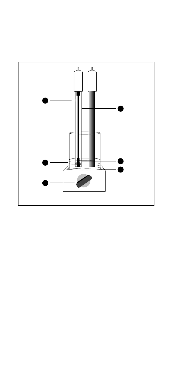
See Figure 1.
– Stir all standards and samples at a uniform rate during
measurement. Magnetic stirrers may generate sufficient heat to
change solution temperature. Place a piece of insulating material
such as cork, cardboard, or Styrofoam between the stirrer
and sample beaker.
– Prepare fresh working standards for calibration daily.
– Always rinse electrode(s) with distilled water between
measurements. Shake after rinsing to prevent solution
carryover. Blot dry.
– Allow all standards and samples to come to the same
temperature for precise measurement.
_ The 90-02 reference electrode (when used with the 94-16
Silver/Sulfide Half-Cell Electrode) should be submerged to the
same depth as the silver/sulfide electrode.
_ Concentrated samples (> 1 M silver or sulfide) should be diluted
before measurement.
– After immersion in solution, check electrode(s) for any air
bubbles on the sensing element and remove by gently tapping
the electrode(s).
– For high ionic strength samples, prepare standards with
composition similar to that of the sample.
Page 16
12
1. Filling hole should be uncovered (90-02 or 96-16)
2. Fresh standard
3. Stir all samples and standards
4. Filling solution level must be higher than sample level
5. Reference junction must be immersed
6. Place insulation between stirrer and beaker
1
2
3
4
5
6
Figure 1 GLP Measuring Hints
Page 17

13
CHOOSING THE RIGHT
MEASURING TECHNIQUE
A variety of analytical techniques are available to the analyst.
Direct Measurement is a simple procedure for measuring a large
number of samples. Only one meter reading is required for each
sample. Calibration is performed in a series of standards. The
concentration of the samples is determined by comparison to the
standards. ISA or SAOB II is added to all solutions to ensure that
samples and standards have similar ionic strength, proper pH, and
to reduce the effect of interfering ions.
Low-Level Measurement is a similar method to Direct
Measurement. This method is recommended when the expected
sample concentration is less than 0.5 ppm or 4.6 x 10
-6
M Ag+or
0.32 ppm or 1 x 10⁻⁵M S2-. A minimum three point calibration is
recommended to compensate for the electrode’s non-linear
response at these concentrations. A special procedure describes
the best means of preparing low-level calibration standards.
Known Addition is a useful method for measuring samples, since
calibration is not required. This method is recommended when
measuring only a few samples, or when samples have a high
(> 0.1 M) ionic strength, or a complicated background matrix.
Refer to Theory of Operation for explanation of these effects. The
electrodes are immersed in the sample solution and an aliquot of a
standard solution containing the measured species is added to the
sample. From the change in potential before and after the addition,
the original sample concentration is determined. As in direct
calibration, any convenient concentration unit can be used.
Analate Subtraction is also a useful method for measuring
samples, since calibration is not required. The electrodes are
immersed in a reagent solution that contains a species that the
electrode senses, and that reacts with the samples. It is useful
when sample size is small, for samples for which a stable standard
is difficult to prepare, and for viscous or very concentrated samples.
The method is not suited for very dilute samples. It is also
necessary to know the stoichiometric ratio between standard
and sample.
Page 18

14
Titrations are quantitative analytical techniques for measuring the
concentration of a species by incremental addition of a reagent
(titrant) that reacts with the sample species. Sensing electrodes
can be used for determination of the titration endpoint. Ionselective electrodes are useful as endpoint detectors, because they
are unaffected by sample color or turbidity. Titrations are
approximately 10 times more precise than direct calibration, but are
more time-consuming. For sulfide measurements, titrations
produce an extremely sharp endpoint, even at low levels of
sulfide. Titration is the recommended measurement method for
sulfide samples.
Indicator Titration Methods are useful for measuring ionic species
where an ion-specific electrode does not exist. With these methods
the electrodes sense a reagent species that has been added to the
sample before titration. A procedure for measuring low levels of
cyanide ion down to 0.03 ppm, using the silver electrode, is
described in the Low-Level Cyanide Indicator Method.
Page 19

15
SILVER MEASUREMENT
PROCEDURES
Direct Measurement
The following direct measurement procedures are recommended for
“high-level” measurements. All samples must be in the electrode’s
linear range, greater than 0.5 ppm or 4.6 x 10
-6
M Ag+. A two point
calibration is sufficient, though more points can be used if desired.
With ISE meters, such as the Orion 920A, 720A, 710A, or 290A,
sample concentrations can be read directly from the meter. Refer
to the meter instruction manual for calibration details. When using
a mV meter, a calibration curve can be prepared on semilogarithmic graph paper, or a linear regression (against logarithmic
concentration values) can be performed at the user’s discretion
using a spreadsheet or graphing program.
Measuring Hints
– Standard concentrations should bracket the expected
sample concentrations.
– Always add 2 mL ISA per 100 mL of silver standard or sample.
– For high ionic strength samples, having an ionic strength of 0.1
M or greater, prepare standards with a composition similar to
that of the samples, or measure the samples using the known
addition method.
– During calibration, measure the least concentrated standard first,
and work up to the most concentrated.
– The best method for preparation of standards is by serial
dilution. This procedure involves preparing an initial standard
that is diluted, using volumetric glassware, to prepare a second
standard solution. The second is similarly diluted to prepare a
third standard, and so on, until the desired range of standards
has been prepared.
– Store all silver samples and standards away from light.
– Verify this procedure by measuring a standard of known
concentration as an unknown or by spiking a sample with
silver standard.
– Review section entitled GLP Measuring Hints.
Page 20

16
Direct Measurement Procedure using ISE Meter
See individual meter instruction manuals for more specific
calibration information.
1. Prepare electrode(s) as described in Electrode Preparation.
2. Connect electrode(s) to the meter, and adjust the meter to
measure concentration.
3. Prepare two standards that bracket the expected sample range
and differ in concentration by a factor of ten. Standards can be
prepared in any concentration unit to suit the particular analysis
requirement. All standards should be at the same temperature
as the samples. For details on temperature effects on electrode
performance, refer to Temperature Effects.
4. Measure 100 mL of each standard and sample into separate
150 mL beakers. Add 2 mL ISA to each beaker.
NOTE: Other solution volumes may be used, as long as the
ratio of solution to ISA remains 50:1. Stir thoroughly.
5. Rinse electrode(s) with distilled water, blot dry and place into the
beaker containing the most dilute standard. Wait for a stable
reading, then calibrate the meter to display the value of the
standard as described in the meter instruction manual.
6. Rinse electrode(s) with distilled water, blot dry, and place into
the beaker with the next standard. Wait for a stable reading, then
adjust the meter to display the value of this standard, as
described in the meter instruction manual.
7. Repeat step 6 for all standards, working from the least
concentrated to most concentrated standard.
8. Rinse electrode(s) with distilled water, blot dry, and place into
sample. The concentration will be displayed on the meter.
Page 21
17
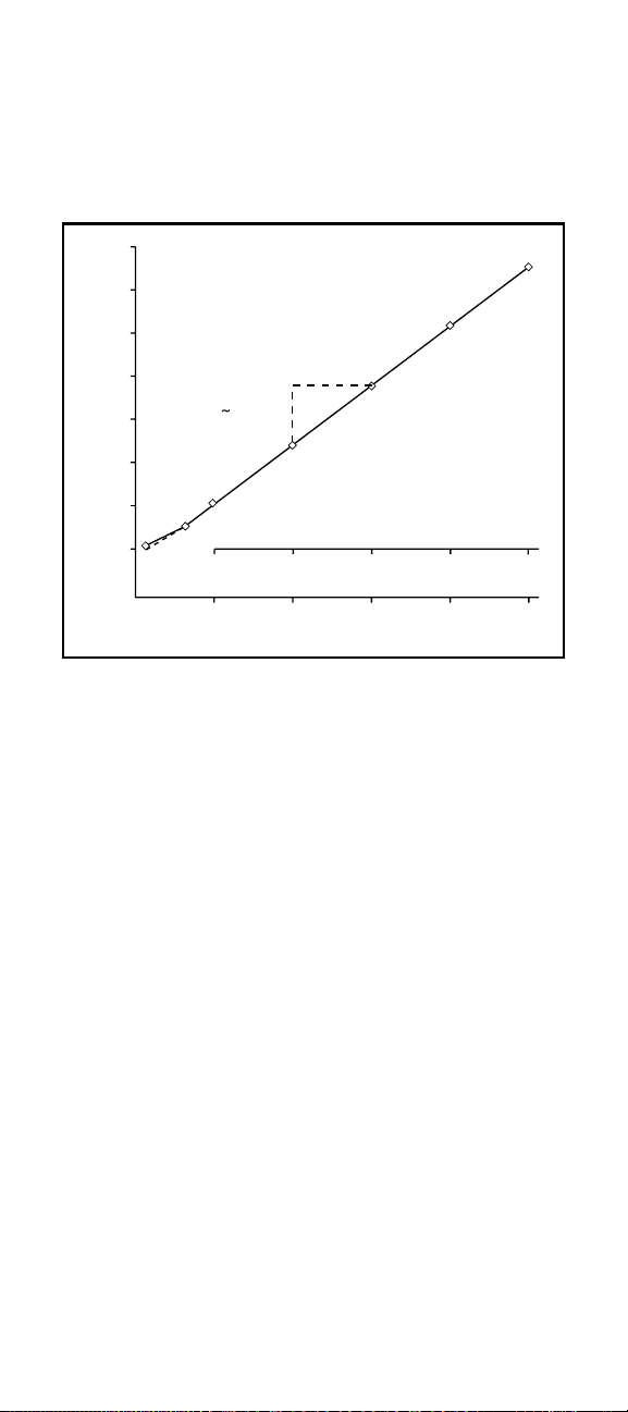
Figure 2
Typical Silver Calibration Curve
In the direct measurement procedure, a calibration curve is
constructed on semi-logarithmic paper. Electrode potentials of
standard solutions are measured and plotted on the linear axis
against their concentrations on the log axis. In the
linear regions of the curves, only two standards are needed
to determine a calibration curve. In nonlinear regions, more points
must be taken. The direct measurement procedures
in this manual are given for concentrations in the region
of linear response. Low-level measurement procedures are given
for measurements in the non-linear region. This curve is only used
as an example. Actual mV values may differ.
550.0
450.0
400.0
350.0
300.0
250.0
200.0
10
-5
11010210
3
10
4
Molarity
ppm silver
10
-4
10
-3
10
-2
10
-1
500.0
Electrode potential
(mV)
57 mV
10-fold change
Page 22

18
Direct Measurement Procedure using a meter with
mV readout
1. Prepare electrode(s) as described in Electrode Preparation.
2. Connect electrode(s) to the meter, and adjust the meter to
measure mV.
3. Prepare two standards that bracket the expected sample range
and differ in concentration by a factor of ten. Standards can be
prepared in any concentration unit to suit the particular analysis
requirement. All standards should be at the same temperature
as the samples. For details on temperature effects on electrode
performance, refer to Temperature Effects.
4. Measure 100 mL of each standard and sample into separate
150 mL beakers. Add 2 mL ISA to each beaker.
NOTE: Other solution volumes may be used, as long as the
ratio of solution to ISA remains 50:1. Stir thoroughly.
5. Rinse electrode(s) with distilled water, blot dry and place into the
beaker containing the most dilute standard. When a stable
reading is displayed,record the mV value and corresponding
standard concentration.
6. Rinse electrode(s) with distilled water, blot dry, and place
into the beaker with the next standard. When a stable reading
is displayed, record the mV value and corresponding
standard concentration.
7. Repeat step 6 for all standards, working from the
least concentrated to most concentrated standard.
8. Using semi-logarithmic graph paper, prepare a calibration curve
by plotting the millivolt values on the linear axis and the
standard concentration values on the logarithmic axis.
See Figure 2.
9. Rinse electrode(s) with distilled water, blot dry, and place into
sample. When a stable reading is displayed, record the
mV value.
10.Using the calibration curve prepared in step 8, determine the
unknown sample concentration.
Page 23

19
Low-Level Measurements
These procedures are for solutions with a silver concentration of
less than 0.5 ppm or 4.6 x 10⁻⁶M Ag+, those within the non-linear
range of the silver electrode. See Figure 2. In low-level
measurements, at least three standards are required for calibration
to compensate for the electrode’s non-linearity.
Measuring Hints
– Use plastic labware for low-level silver measurements.
– For solutions low in silver but high in total ionic strength
(greater than 10
-1
M), perform the same procedure with one
change: prepare a calibration solution with a composition similar
to the sample.
– The choice of standard concentrations is important for obtaining
the best electrode performance and most rapid analysis time.
Here are some guidelines:
• Ideally, standard concentrations should bracket the
expected sample concentrations.
• When measuring sub-ppm levels with Orion 920A, 720A,
710A, or 290A, take advantage of the autoblank feature.
It does not require a zero standard, but can perform
blank correction as long as the lowest standard
concentration is in the non-linear range of the electrode.
Electrodes are very slow in the absence of a measurable
concentration and a multipoint calibration generally will
be less accurate when “zero” is included as a standard.
Standard concentrations should be chosen such that the
lowest standard value is larger than the blank value
obtained, and the second lowest standard should be at
least twice that of the lowest. See your A-Series meter
instruction manual for additional information on blank
correction.
Page 24

20
• If using an ISE meter, such as the Orion EA 940, that
allows a blank solution value to be entered, it is
recommended to do so. A blank solution is prepared
with the same dilution water and ISA used when
preparing calibration standards. This solution corrects
for the curves non-linearity as well as for any background
ion contamination that might be present in the standard
solutions. When a blank value is entered, it represents
the zero point of the curve, and each standard is
measured against that blank.
• When not using an ISE meter, a calibration curve can be
drawn on semi-logarithmic graph paper, or the data can
be processed at the discretion of the user by means of a
spreadsheet or graphing program with a non-linear curve
fitting feature.
• When using an ISE meter, such as the Orion 920A, 720A,
710A, or 290A, three calibration points are sufficient. If a
calibration curve is prepared manually, additional points
may be helpful to facilitate drawing the curve.
– Remember to stir all standards and samples at a uniform rate.
– Typical response time for this electrode is approximately 1
minute. Low-level measurements may take longer to stabilize.
Wait for 3 minutes or the meter’s “ready” signal, whichever
takes longer, before calibrating the meter or recording the
sample value.
– Review section entitled GLP Measuring Hints.
Page 25

21
Low-Level Measurement Procedure using ISE Meter
Follow the above procedure entitled Direct Measurement
Procedure using ISE Meter except substitute low-level ISA (see
page 18). Use at least three calibration standards. Read the
Measuring Hints section on pg. 21 in order to select appropriate
standard concentrations. Refer to the meter instruction manual for
detailed calibration procedures. If not using an Orion 920A, 720A,
710A, or 290A with the autoblank feature, preparation of a blank
solution is recommended to ensure
accurate results.
Low-Level Measurement Procedure using a meter with mV
readout (see Table 3)
Set Up
1. Prepare electrode(s) as described in Electrode Preparation.
2. Connect electrode(s) to the meter. Set the meter to read mV.
3. Select a standard solution. Use either a 10 ppm silver standard
or a 10
-4
M silver solution.
4. Prepare a low-level ISA solution by diluting 20 mL of the
silver ionic strength adjustor, Orion 940011, to 100 mL with
distilled water.
NOTE: use this low-level ISA for low-level
measurements only.
Measurement
1. Measure 100 mL distilled water into 150 mL beaker. Add 1 mL
low-level ISA.
2. Rinse electrode(s) with distilled water, blot dry, and place into
beaker. Stir thoroughly.
3. Add increments of the 10 ppm or 10
-4
M standard to the beaker
using steps outlined in Table 3. Record stable millivolt reading
after each increment. On semi-logarithmic paper, plot the
concentration (log axis) against the millivolt potential (linear
axis). See Figure 2. Prepare a new calibration curve with
fresh standards each day.
Page 26

22
4. Measure 100 mL of sample into a beaker. Add 1 mL low-level
ISA. Rinse the electrode(s) with distilled water, blot dry, and
place into the sample.
5. Stir thoroughly. When a stable reading is displayed, record the
mV value.
6. Determine the sample concentration corresponding to the
measured potential from the low-level calibration curve.
Table 3
Preparing a Calibration Curve For Low-Level
Measurements making 10 ppm silver additions
Graduated
Pipet Added Concentration
Step Size Volume ppm
11 mL 0.1 mL 0.01
21 mL 0.3 mL 0.04
31 mL 0.6 mL 0.10
42 mL 2.0 mL 0.30
Preparing a Calibration Curve For Low-Level
Measurements making 10
-4
M silver additions
Graduated
Pipet Added Concentration
Step Size Volume Molarity
11 mL 0.1 mL 1.0 x 10
-7
21 mL 0.3 mL 4.0 x 10
-7
31 mL 0.6 mL 1.0 x 10
-6
42 mL 2.0 mL 3.0 x 10
-6
Additions of 10 ppm or 10-4M standard to 100 mL distilled water,
plus 1 mL low-level ISA.
Page 27

23
Known Addition
Known addition is a convenient technique for measuring samples in
the linear range, greater than 0.5 ppm Ag+, because no calibration
curve is needed. The sample potential is measured before and after
addition of a standard solution. Many meters, such as the Orion
920A, have the known addition algorithms preprogrammed. This
programming allows multiple standard additions to be made to the
sample, thereby allowing the meter to calculate the electrode slope
as well. Having the ability to read the sample concentration directly
from the meter is a great convenience and ensures accuracy.
Measuring Hints
– Sample concentration should be known within a factor of three.
– Concentration should approximately double as a result of the
first standard addition.
– With double or multiple known addition, the final addition should
be 10 to 100 times the sample concentration.
– All samples and standards should be at the same temperature.
– Add 2 mL ISA to every 100 mL of sample before analysis.
– Standard addition volume should be no more than 10% of the
sample volume, or standard should be pre-treated with ISA in a
50:1 ratio. See Table 4.
– Review section entitled GLP Measuring Hints.
Set-up
1. Prepare electrode(s) as described in Electrode Preparation.
2. Connect electrode(s) to the meter.
3. Prepare a standard solution that, upon addition to the sample,
will cause the concentration of silver to double. Refer to Table 4
as a guideline.
4. Determine the slope of the electrode by performing the
procedure under Checking Electrode Operation (Slope).
Page 28

24
Known Addition Measurement Procedure using an ISE meter
with KA program
See individual meter instruction manual for more
specific information.
1. Set the meter to measure in the known addition mode.
2. Measure 100 mL of sample into a beaker. Add 2 mL ISA. Stir
thoroughly. Rinse electrode(s) with distilled water, blot dry, and
place in sample solution.
3. When a stable reading is displayed, program the meter as
described in the meter instruction manual.
4. Pipet the appropriate amount of standard solution into the
beaker. Stir thoroughly.
5. When a stable reading is displayed, record the
sample concentration.
Table 4
Standard Addition volumes
Volume
of Addition Concentration of Standard
1 mL 100 x sample concentration
5 mL 20 x sample concentration
10 mL* 10 x sample concentration
* Most convenient volume to use.
Page 29

25
Known Addition Measurement Procedure using a meter with
mV readout
1. Set the meter to millivolt mode.
2. Measure 100 mL of the sample into a 150 mL beaker.
Add 2 mL ISA. Stir thoroughly.
3. Rinse electrode(s) with distilled water, blot dry, and place
into beaker. When a stable reading is displayed, record the
mV value as E
1
.
4. Pipet the appropriate amount of standard solution into the
beaker. See Table 4. Stir thoroughly.
5. When a stable reading is displayed, record the mV value as E
2
.
Subtract the first reading from the second to find DE.
6. From Table 6, find the value Q, that corresponds to the change
in potential, DE. To determine the original sample concentration,
multiply Q by the concentration of the added standard:
Csam = Q*Cstd
where:
Cstd = standard concentration
Csam = sample concentration
Q = reading from known addition table
The table of Q values is calculated for a 10% volume change for
electrodes with slopes of 57, 58, 59, 60 mV/ decade for silver. The
equation for the calculation of Q for different slopes and volume
changes is given below:
Q= p * r
(1+p)(10
∆E/S
)-1
where:
Q = reading from known addition table
∆E = E
2
- E
1
S = slope of the electrode
p = (volume of standard) / (volume of sample & ISA)
r = (volume of sample & ISA) / (volume of sample)
Page 30

26
If it is more convenient, a simple spreadsheet can be set up to
calculate known addition results, using any ratio of sample to
addition. A typical worksheet is shown in Table 5. The numbers
shown are examples, but the formulas and their locations should be
copied exactly.
Table 5
Calculating known addition for silver samples using Lotus, Excel,
or Quattro Spreadsheet
A B C
1 Enter Value
2 Vol. of Sample & ISA, mL: 102
3 Vol. of Addition, mL: 10
4 Concentrn. of Addition: 10
5 Vol. of Sample 100
6 Initial mV Reading 45.3
7 Final mV Reading 63.7
8 Electrode Slope 59.2
9
10 Derived Values
11 Delta E +C7 - C6
12 Solution Vol. Ratio +C3/C2
13 Antilog Term +10^ (C11/C8)
14 Sample Vol. Ratio +C2/C5
15 Q Term +C12*C14/
{
[(1 +C12)*C13]-1
}
16 Calculated Initial Conc. in
same units as addition: +C15*C4
NOTE: for Excel, use = instead of + at start of formula
Page 31

27
Table 6
Known Addition Table for an added volume one-tenth the total
volume. Slopes, in the column headings, are in units of
mV/decade.
Q, Concentration Ratio
(slope)
-∆E 57.2 58.2 59.2 60.1
5.0 0.2917 0.2957 0.2996 0.3031
5.2 0.2827 0.2867 0.2906 0.2940
5.4 0.2742 0.2781 0.2820 0.2854
5.6 0.2662 0.2700 0.2738 0.2772
5.8 0.2585 0.2623 0.2660 0.2693
6.0 0.2512 0.2550 0.2586 0.2619
6.2 0.2443 0.2480 0.2516 0.2548
6.4 0.2377 0.2413 0.2449 0.2480
6.6 0.2314 0.2349 0.2384 0.2416
6.8 0.2253 0.2288 0.2323 0.2354
7.0 0.2196 0.2230 0.2264 0.2295
7.2 0.2140 0.2174 0.2208 0.2238
7.4 0.2087 0.2121 0.2154 0.2184
7.6 0.2037 0.2070 0.2102 0.2131
7.8 0.1988 0.2020 0.2052 0.2081
8.0 0.1941 0.1973 0.2005 0.2033
8.2 0.1896 0.1927 0.1959 0.1987
8.4 0.1852 0.1884 0.1914 0.1942
8.6 0.1811 0.1841 0.1872 0.1899
8.8 0.1770 0.1801 0.1831 0.1858
9.0 0.1732 0.1762 0.1791 0.1818
9.2 0.1694 0.1724 0.1753 0.1779
9.4 0.1658 0.1687 0.1716 0.1742
9.6 0.1623 0.1652 0.1680 0.1706
9.8 0.1590 0.1618 0.1646 0.1671
10.0 0.1557 0.1585 0.1613 0.1638
10.2 0.1525 0.1553 0.1580 0.1605
10.4 0.1495 0.1522 0.1549 0.1573
10.6 0.1465 0.1492 0.1519 0.1543
10.8 0.1437 0.1463 0.1490 0.1513
11.0 0.1409 0.1435 0.1461 0.1485
11.2 0.1382 0.1408 0.1434 0.1457
11.4 0.1356 0.1382 0.1407 0.1430
11.6 0.1331 0.1356 0.1381 0.1404
11.8 0.1306 0.1331 0.1356 0.1378
12.0 0.1282 0.1307 0.1331 0.1353
12.2 0.1259 0.1283 0.1308 0.1329
12.4 0.1236 0.1260 0.1284 0.1306
12.6 0.1214 0.1238 0.1262 0.1283
12.8 0.1193 0.1217 0.1240 0.1261
13.0 0.1172 0.1195 0.1219 0.1239
13.2 0.1152 0.1175 0.1198 0.1218
13.4 0.1132 0.1155 0.1178 0.1198
13.6 0.1113 0.1136 0.1158 0.1178
13.8 0.1094 0.1117 0.1139 0.1159
Page 32

28
Table 6 (continued)
Q, Concentration Ratio
(slope)
-∆E 57.2 58.2 59.2 60.1
14.0 0.1076 0.1098 0.1120 0.1140
14.2 0.1058 0.1080 0.1102 0.1121
14.4 0.1041 0.1063 0.1084 0.1103
14.6 0.1024 0.1045 0.1067 0.1086
14.8 0.1008 0.1029 0.1050 0.1069
15.0 0.0992 0.1012 0.1033 0.1052
15.5 0.0953 0.0973 0.0994 0.1012
16.0 0.0917 0.0936 0.0956 0.0974
16.5 0.0882 0.0902 0.0921 0.0938
17.0 0.0850 0.0869 0.0887 0.0904
17.5 0.0819 0.0837 0.0856 0.0872
18.0 0.0790 0.0808 0.0825 0.0841
18.5 0.0762 0.0779 0.0797 0.0813
19.0 0.0736 0.0753 0.0770 0.0785
19.5 0.0711 0.0727 0.0744 0.0759
20.0 0.0687 0.0703 0.0719 0.0734
20.5 0.0664 0.0680 0.0696 0.0710
21.0 0.0642 0.0658 0.0673 0.0687
21.5 0.0621 0.0637 0.0652 0.0666
22.0 0.0602 0.0617 0.0631 0.0645
22.5 0.0583 0.0597 0.0612 0.0625
23.0 0.0564 0.0579 0.0593 0.0606
23.5 0.0547 0.0561 0.0575 0.0588
24.0 0.0530 0.0544 0.0558 0.0570
24.5 0.0514 0.0528 0.0541 0.0553
25.0 0.0499 0.0512 0.0525 0.0537
25.5 0.0484 0.0497 0.0510 0.0522
26.0 0.0470 0.0483 0.0495 0.0507
26.5 0.0456 0.0469 0.0481 0.0492
27.0 0.0443 0.0455 0.0468 0.0479
27.5 0.0431 0.0443 0.0455 0.0465
28.0 0.0419 0.0430 0.0442 0.0452
28.5 0.0407 0.0418 0.0430 0.0440
29.0 0.0395 0.0407 0.0418 0.0428
29.5 0.0385 0.0396 0.0407 0.0417
30.0 0.0374 0.0385 0.0396 0.0406
30.5 0.0364 0.0375 0.0385 0.0395
31.0 0.0354 0.0365 0.0375 0.0384
31.5 0.0345 0.0355 0.0365 0.0374
32.0 0.0335 0.0345 0.0356 0.0365
32.5 0.0327 0.0336 0.0346 0.0355
33.0 0.0318 0.0328 0.0337 0.0346
33.5 0.0310 0.0319 0.0329 0.0337
34.0 0.0302 0.0311 0.0320 0.0329
34.5 0.0294 0.0303 0.0312 0.0321
35.0 0.0286 0.0295 0.0305 0.0313
35.5 0.0279 0.0288 0.0297 0.0305
Page 33

29
Table 6 (continued)
Q, Concentration Ratio
(slope)
-∆E 57.2 58.2 59.2 60.1
36.0 0.0272 0.0281 0.0290 0.0298
36.5 0.0265 0.0274 0.0282 0.0290
37.0 0.0258 0.0267 0.0275 0.0283
37.5 0.0252 0.0260 0.0269 0.0276
38.0 0.0246 0.0254 0.0262 0.0270
38.5 0.0240 0.0248 0.0256 0.0263
39.0 0.0234 0.0242 0.0250 0.0257
39.5 0.0228 0.0236 0.0244 0.0251
40.0 0.0223 0.0230 0.0238 0.0245
40.5 0.0217 0.0225 0.0232 0.0239
41.0 0.0212 0.0219 0.0227 0.0234
41.5 0.0207 0.0214 0.0221 0.0228
42.0 0.0202 0.0209 0.0216 0.0223
42.5 0.0197 0.0204 0.0211 0.0218
43.0 0.0192 0.0199 0.0206 0.0213
43.5 0.0188 0.0195 0.0202 0.0208
44.0 0.0183 0.0190 0.0197 0.0203
44.5 0.0179 0.0186 0.0192 0.0198
45.0 0.0175 0.0181 0.0188 0.0194
45.5 0.0171 0.0177 0.0184 0.0190
46.0 0.0167 0.0173 0.0179 0.0185
46.5 0.0163 0.0169 0.0175 0.0181
47.0 0.0159 0.0165 0.0171 0.0177
47.5 0.0156 0.0162 0.0168 0.0173
48.0 0.0152 0.0158 0.0164 0.0169
48.5 0.0148 0.0154 0.0160 0.0166
49.0 0.0145 0.0151 0.0157 0.0162
49.5 0.0142 0.0147 0.0153 0.0158
50.0 0.0139 0.0144 0.0150 0.0155
50.5 0.0135 0.0141 0.0146 0.0151
51.0 0.0132 0.0138 0.0143 0.0148
51.5 0.0129 0.0135 0.0140 0.0145
52.0 0.0126 0.0132 0.0137 0.0142
52.5 0.0124 0.0129 0.0134 0.0139
53.0 0.0121 0.0126 0.0131 0.0136
53.5 0.0118 0.0123 0.0128 0.0133
54.0 0.0116 0.0120 0.0125 0.0130
54.5 0.0113 0.0118 0.0123 0.0127
55.0 0.0110 0.0115 0.0120 0.0125
55.5 0.0108 0.0113 0.0118 0.0122
56.0 0.0106 0.0110 0.0115 0.0119
56.5 0.0103 0.0108 0.0113 0.0117
57.0 0.0101 0.0106 0.0110 0.0114
57.5 0.0099 0.0103 0.0108 0.0112
58.0 0.0097 0.0101 0.0105 0.0110
58.5 0.0095 0.0099 0.0103 0.0107
59.0 0.0093 0.0097 0.0101 0.0105
59.5 0.0091 0.0095 0.0099 0.0103
60.0 0.0089 0.0093 0.0097 0.0101
Page 34

30
Low-Level Chloride Titration
The electrode is a highly sensitive endpoint detector for titration of
silver samples with a halide standard (or vice versa). The low-level
chloride titration is an example of this type of measurement.
Titrations are more time-consuming than direct electrode
measurement, but results are more accurate and reproducible.
With careful technique, titrations accurate to ± 0.1% of the total
chloride ion concentration of the sample can be performed. The
Orion 960 Autochemistry System may be used to automate these
titrations.
Figure 3
Typical Titration of 25 mL (before dilution) 0.001 M Chloride
Sample with 0.01 M AgNO
3
10-fold change
500
mV
400
300
200
ml 0.01 M AgNO
3
0 1 2 3 4 5 6 7 8 9 10
Page 35

31
Set-up
1. Prepare electrode(s) as described in Electrode Preparation.
2. Connect electrode(s) to the meter.
3. Prepare a titrant solution 10 - 20 times as concentrated as the
sample by dilution of the 0.1 M silver solution.
Measurement
1. Place 50 mL of sample into a 150 mL beaker. Place electrode(s)
in the sample. Stir thoroughly.
2. Using a 10 mL burette, add increments of titrant and plot
electrode potential against mL of titrant added. The endpoint is
the point of greatest slope (inflection point). See Figure 3.
3. Calculate the sample concentration before dilution:
C
sam
= Ct(Vt/V
sam
)
where:
C
sam
= sample concentration
C
t
= titrant concentration
V
sam
= sample volume
V
t
= titrant volume added at endpoint.
Page 36

32
Low-Level Cyanide Indicator Method
The Ag/S electrode can be used for cyanide measurements down to
0.03 ppm CN-. A small amount of KAg(CN)2is added to the
solution as an indicator. The ion Ag(CN)
2
-
dissociates to form some
silver and cyanide ions, and the electrode measures the silver
concentration. Since the degree of dissociation of the ion depends
on the free cyanide concentration, measurement of the silver
concentration is an indirect measure of the cyanide concentration.
Cyanide complexed by copper, nickel, cobalt, or iron cannot be
measured directly with this method. These complexes may be
broken by distillation according to ASTM Method D 2036,
Section 12.2.
Sulfide ion is an interference for the method, but it can be removed
by precipitation with cadmium.
Set-up
1. Prepare electrode(s) as described in Electrode Preparation.
2. Connect electrode(s) to the meter.
3. Prepare the following solutions:
Ethylemediamine – anhydrous (98% purity or better) for the
removal of formaldehyde.
Silver Nitrate Titrant – (1 mL = 1 mg CN
-
) Crush approximately
5 g of reagent grade silver nitrate (AgNO3) crystals and dry at
150 °C for 1 hour. Dissolve 3.265 g in distilled water and dilute
to 1 liter.
NaOH Diluent – Dissolve 25 g reagent grade sodium hydroxide
(NaOH) in distilled water and dilute to 1 liter. For diluting
cyanide standard solutions.
Silver Potassium Cyanide [KAg(CN)
2
] – Reagent grade or
equivalent. Available from suppliers of electroplating chemicals.
Indicator/Buffer – Add 33 g of reagent grade disodium hydrogen
phosphate (Na
2
HPO4 • 7H2O) in about 80 mL water. Stir for
about one half hour to saturate the solution with phosphate.
Add 2.2 g of reagent grade sodium hydroxide (NaOH),
0.1 g of silver potassium cyanide [KAg(CN)2], and 3.4 mL of
ethylemediamine, and dissolve by thorough mixing with distilled
water. Dilute to 100 mL with distilled water. Check the
solution before use for precipitation of any solids; discard if a
precipitate appears.
Page 37

33
Potassium Cyanide – Stock solution (1000 ppm,
1 mL = approximately 1 mg CN
-
) Dissolve approximately 2 g of
reagent grade sodium hydroxide (NaOH) and 2.51 g of reagent
grade potassium cyanide (KCN) in 1 liter of distilled water.
CAUTION: KCN is highly toxic. Avoid contact or inhalation.
Standardization of KCN Stock Solution
1. Standardize the KCN stock solution by titration with silver nitrate
titrant. Pipet 20 mL of the KCN stock solution into a 150 mL
beaker. Immerse the electrode(s) and stir gently.
2. Fill a 25 mL burette with the silver nitrate titrant.
3. Add increments of 0.5 to 1 mL in the beginning of the titration
and about 0.1 to 0.25 mL in the region of the endpoint.
Continue the titration 3 - 4 mL past the endpoint.
4. Record the solution potential after each addition of titrant and
plot mL of titrant added versus mV readings on standard graph
paper. The point of inflection is taken as the endpoint.
5. Prepare a blank solution by dissolving 2 g reagent grade NaOH
per liter. Titrate 20 mL of blank solution according to
instructions above.
6. Calculate the cyanide concentration of the stock
solutions follows:
CN
-
, (ppm) = (A - B) x 1000/ C
where:
A = mL of titrant added at the endpoint
(cyanide solution)
B = mL of titrant added at the endpoint (blank)
C = mL of cyanide stock solution used for
the titration
7. Standardize the stock solution each week because the solution
loses strength gradually.
8. Prepare a 100 ppm cyanide standard daily by dilution of the
stock solution with NaOH diluent. The 100 ppm solution is
prepared by pipetting a volume, V, into a 100 mL volumetric
flask. The volume, V, is calculated from:
V = 10000/D
where D = concentration (ppm) of cyanide stock solution
9. Prepare 10 and 1 ppm standards daily by serial dilution with
the NaOH diluent. For lower levels of cyanide, prepare 0.1 and
0.01 ppm standards as well.
Page 38

34
Measurement of Sample
Set-up
1. Prepare electrode(s) as described in Electrode Preparation.
2. Connect electrode(s) to the meter.
3. Use the two standards prepared in step 9. Standards should be
at the same temperature as the samples. For details on
temperature effects on electrode performance, refer to
Temperature Effects.
Indicator method procedure using ISE Meter
See individual meter instruction manual for more specific
calibration information.
1. Measure 100 mL of each standard and sample into separate
150 mL beakers. Add 2 mL Indicator/ Buffer to each beaker.
Stir thoroughly.
2. Rinse electrode(s) with distilled water, blot dry and place into the
beaker containing the most dilute standard. Wait for a stable
reading, then calibrate the meter to display the value of the
standard as described in the meter instruction manual.
3. Rinse electrode(s) with distilled water, blot dry, and place into
the beaker with the next standard. Wait for a stable reading, then
adjust the meter to display the value of this standard, as
described in the meter instruction manual.
4. Repeat step 3 for all standards, working from the least
concentrated to most concentrated standard. Slope will be
between -116 to -122 mV/decade.
5. Rinse electrode(s) with distilled water, blot dry, and place into
sample. The concentration will be displayed on the meter.
Page 39

35
Indicator method procedure using a meter with mV readout
1. Measure 100 mL of each standard and sample into separate
150 mL beakers. Add 2 mL Indicator/ Buffer to each beaker.
Stir thoroughly.
2. Rinse electrode(s) with distilled water, blot dry and place into the
beaker containing the most dilute standard. When a stable
reading is displayed, record the mV value and corresponding
standard concentration.
3. Rinse electrode(s) with distilled water, blot dry, and place
into the beaker with the next standard. When a stable reading
is displayed, record the mV value and corresponding
standard concentration.
4. Repeat step 3 for all standards, working from the least
concentrated to most concentrated standard.
5. Using semi-logarithmic graph paper, prepare a calibration curve
by plotting the millivolt values on the linear axis and the
standard concentration values on the logarithmic axis.
See Figure 3.
6. Rinse electrode(s) with distilled water, blot dry, and place
into sample. When a stable reading is displayed, record the
mV value.
7. Using the calibration curve prepared in step 5, determine the
unknown sample concentration.
Page 40

36
SULFIDE MEASUREMENT
PROCEDURES
Direct Measurement
The following direct measurement procedures are recommended for
“high-level” measurements. All samples must be in the electrode’s
linear range, greater than 0.32 ppm or 10
-5
M S2-. A two point
calibration is sufficient, though more points can be used if desired.
With ISE meters, such as the Orion 920A, 720A, 710A, or 290A,
sample concentrations can be read directly from the meter. Refer
to the meter instruction manual for calibration details. When using
a mV meter, a calibration curve can be prepared on semilogarithmic graph paper, or a linear regression (against logarithmic
concentration values) can be performed at the user’s discretion
using a spreadsheet or graphing program.
Measuring Hints
– Standard concentrations should bracket the expected
sample concentrations.
– Always dilute samples and standards in a 1:1 ratio with SAOB II.
For example, 25 mL of sample and 25 mL of SAOB II.
– For high ionic strength samples, having an ionic strength of
0.1 M or greater, prepare standards with a composition similar
to that of the samples, or measure the samples using the known
addition method.
– During calibration, measure the least concentrated standard first,
and work up to the most concentrated.
– The best method for preparation of standards is by serial
dilution. This procedure involves preparing an initial standard
that is diluted, using volumetric glassware, to prepare a second
standard solution. The second is similarly diluted to prepare a
third standard, and so on, until the desired range of standards
has been prepared.
– Dilute sulfide samples 1:1 with SAOB II as they are collected,
except when analate subtraction is the measurement technique.
NOTE: If samples have been preserved with
SAOB II DO NOT add more SAOB II before measuring.
– Always use deaerated water when preparing sulfide standards to
prevent the oxidation of sulfide.
– Verify this procedure by measuring a standard of known
concentration as an unknown or by spiking a sample with
sulfide standard.
– Review section entitled GLP Measuring Hints.
Page 41

37
Direct Measurement Procedure using ISE Meter
See individual meter instruction manuals for more specific
calibration information.
1. Prepare electrode(s) as described in Electrode Preparation.
2. Connect electrode(s) to the meter, and adjust the meter to
measure concentration.
3. Prepare two standards that bracket the expected sample range
and differ in concentration by a factor of ten. Standards can be
prepared in any concentration unit to suit the particular analysis
requirement. All standards should be at the same temperature
as the samples. For details on temperature effects on electrode
performance, refer to Temperature Effects.
4. Measure 25 mL of each standard and sample into separate
150 mL beakers. Add 25 mL SAOB II to each beaker.
NOTE: Other solution volumes may be used, as long as the
ratio of solution to SAOB II remains 1:1.
Stir thoroughly.
5. Rinse electrode(s) with distilled water, blot dry and place into
the beaker containing the most dilute standard. Wait for a stable
reading, then calibrate the meter to display the value of the
standard as described in the meter instruction manual.
6. Rinse electrode(s) with distilled water, blot dry, and place into
the beaker with the next standard. Wait for a stable reading, then
adjust the meter to display the value of this standard, as
described in the meter instruction manual.
7. Repeat step 6 for all standards, working from the least
concentrated to most concentrated standard.
8. Rinse electrode(s) with distilled water, blot dry, and place into
sample. The concentration will be displayed on the meter.
Page 42

38
Figure 4
Typical Sulfide Calibration Curve
In the direct measurement procedure, a calibration curve is
constructed on semi-logarithmic paper. Electrode potentials
of standard solutions are measured and plotted on the linear axis
against their concentrations on the log axis. In the linear regions
of the curves, only two standards are needed to determine a
calibration curve. In nonlinear regions, more points must be taken.
This curve is only used as an example. Actual mV values
may differ.
-790.0
-780.0
-770.0
-760.0
-750.0
-740.0
-730.0
10
-5
0.1 1 10 10
2
10
3
Molarity
ppm sulfide
10
-4
10
-3
10
-2
10
-1
-800.0
-840.0
-830.0
-820.0
-810.0
-850.0
Electrode
potential
(mV)
-28 mV
10-fold change
Page 43

39
Direct Measurement Procedure using a meter with
mV readout
1. Prepare electrode(s) as described in Electrode Preparation.
2. Connect electrode(s) to the meter, and adjust the meter to
measure mV.
3. Prepare two standards that bracket the expected sample range
and differ in concentration by a factor of ten. Standards can be
prepared in any concentration unit to suit the particular analysis
requirement. All standards should be at the same temperature
as the samples. For details on temperature effects on electrode
performance, refer to Temperature Effects.
4. Measure 25 mL of each standard and sample into separate
150 mL beakers. Add 25 mL SAOB II to each beaker.
NOTE: Other solution volumes may be used, as long as the
ratio of solution to SAOB II remains 1:1.
Stir thoroughly.
5. Rinse electrode(s) with distilled water, blot dry and place into the
beaker containing the most dilute standard. When a stable
reading is displayed, record the mV value and corresponding
standard concentration.
6. Rinse electrode(s) with distilled water, blot dry, and place
into the beaker with the next standard. When a stable reading
is displayed, record the mV value and corresponding
standard concentration.
7. Repeat step 6 for all standards, working from the least
concentrated to most concentrated standard.
8. Using semi-logarithmic graph paper, prepare a calibration
curve by plotting the millivolt values on the linear axis and the
standard concentration values on the logarithmic axis.
See Figure 4.
9. Rinse electrode(s) with distilled water, blot dry, and place
into sample. When a stable reading is displayed, record the
mV value.
10.Using the calibration curve prepared in step 8, determine the
unknown sample concentration.
Page 44

40
Analate Subtraction Measurements
Analate subtraction is recommended for occasional sulfide
measurements because it uses a silver standard solution rather than
the easily oxidized sulfide standard solution. The sample must not
contain species that react with silver (e.g., halide ions or SAOB II).
All concentration units are moles per liter. Use Table 2 to convert
to ppm after measurement.
NOTE: DO NOT dilute sample with SAOB II for
this procedure.
Set-up
1. Prepare electrode(s) as described in Electrode Preparation.
2. Connect electrode(s) to the meter.
3. Prepare a silver standard solution about one to one half the
expected sample sulfide concentration by diluting 0.1 M silver
nitrate standard. Add 2 mL ISA (Orion 940011) to every 100 mL
of standard.
Analate subtraction procedure using an ISE meter
See individual meter instruction manuals for more
specific information.
1. Measure 100 mL of the silver standard into a beaker. Rinse
electrode(s) with distilled water, blot dry, and place in standard
solution. Stir thoroughly.
2. When a stable reading is displayed, calibrate the meter as
described in the meter instruction manual.
3. Pipet 10 mL of sulfide sample into the silver standard.
Stir thoroughly.
4. When a stable reading is displayed, record the
sample concentration.
Page 45

41
Analate subtraction procedure using a meter with mV readout
1. Adjust the meter to measure mV.
2. Measure 100 mL of the silver standard into a beaker. Rinse
electrode(s) with distilled water, blot dry, and place in standard
solution. Stir thoroughly.
3. When a stable reading is displayed, record the mV value.
4. Pipet 10 mL of sulfide sample into the silver standard.
Stir thoroughly.
5. When a stable reading is displayed, record the mV value.
6. Determine the potential change, ∆E, by subtracting the first
reading from the second.
7. Find the concentration ratio, Q, corresponding to the potential
change, E, in Table 7. Calculate the sample sulfide
concentration in moles per liter:
Csam = 0.5QC
std
where:
C
sam
= sample concentration
Q= concentration ratio from Table 7
C
std
= concentration of silver standard in moles/liter
Page 46

42
Table 7
Analate Subtraction Table Slopes, in the column headings, are in
units of mV/decade
Q, Concentration Ratio
(slope)
-∆E 57.2 58.2 59.2 60.1
5.0 0.503 0.487 0.472 0.458
5.2 0.539 0.523 0.507 0.493
5.4 0.575 0.558 0.542 0.527
5.6 0.610 0.593 0.576 0.561
5.8 0.645 0.628 0.611 0.595
6.0 0.680 0.662 0.645 0.629
6.2 0.715 0.696 0.679 0.662
6.4 0.749 0.730 0.712 0.695
6.6 0.783 0.764 0.745 0.728
6.8 0.817 0.797 0.778 0.761
7.0 0.851 0.830 0.811 0.793
7.2 0.884 0.863 0.843 0.825
7.4 0.917 0.896 0.876 0.857
7.6 0.950 0.928 0.908 0.888
7.8 0.982 0.960 0.939 0.920
8.0 1.014 0.992 0.971 0.951
8.2 1.046 1.024 1.002 0.982
8.4 1.078 1.055 1.033 1.012
8.6 1.109 1.086 1.064 1.043
8.8 1.141 1.117 1.094 1.073
9.0 1.172 1.148 1.124 1.103
9.2 1.202 1.178 1.154 1.133
9.4 1.233 1.208 1.184 1.162
9.6 1.263 1.238 1.214 1.191
9.8 1.293 1.268 1.243 1.221
10.0 1.323 1.297 1.272 1.249
10.2 1.352 1.326 1.301 1.278
10.4 1.381 1.355 1.330 1.306
10.6 1.410 1.384 1.358 1.334
10.8 1.439 1.412 1.386 1.362
11.0 1.468 1.441 1.414 1.390
11.2 1.496 1.469 1.442 1.418
11.4 1.524 1.497 1.470 1.445
11.6 1.552 1.524 1.497 1.472
11.8 1.580 1.552 1.524 1.499
12.0 1.607 1.579 1.551 1.526
12.2 1.634 1.606 1.578 1.552
12.4 1.661 1.633 1.605 1.579
12.6 1.688 1.659 1.631 1.605
12.8 1.715 1.685 1.657 1.631
13.0 1.741 1.712 1.683 1.656
13.2 1.767 1.737 1.709 1.682
13.4 1.793 1.763 1.734 1.707
13.6 1.819 1.789 1.759 1.732
13.8 1.844 1.814 1.784 1.757
14.0 1.870 1.839 1.809 1.782
14.2 1.895 1.864 1.834 1.806
14.4 1.920 1.889 1.859 1.831
14.6 1.944 1.913 1.883 1.855
14.8 1.969 1.938 1.907 1.879
15.0 1.993 1.962 1.931 1.903
15.5 2.053 2.021 1.990 1.961
16.0 2.112 2.080 2.048 2.019
16.5 2.169 2.137 2.105 2.076
17.0 2.226 2.193 2.161 2.131
17.5 2.281 2.248 2.215 2.185
Page 47

43
Q, Concentration Ratio
(slope)
-∆E 57.2 58.2 59.2 60.1
18.0 2.335 2.302 2.269 2.239
18.5 2.388 2.355 2.322 2.291
19.0 2.440 2.406 2.373 2.342
19.5 2.491 2.457 2.424 2.393
20.0 2.541 2.507 2.473 2.442
20.5 2.590 2.556 2.522 2.491
21.0 2.638 2.604 2.570 2.538
21.5 2.685 2.651 2.617 2.585
22.0 2.731 2.697 2.663 2.631
22.5 2.777 2.742 2.708 2.676
23.0 2.821 2.786 2.752 2.720
23.5 2.864 2.829 2.795 2.763
24.0 2.907 2.872 2.837 2.805
24.5 2.949 2.914 2.879 2.847
25.0 2.990 2.954 2.920 2.888
25.5 3.030 2.995 2.960 2.928
26.0 3.069 3.034 2.999 2.967
26.5 3.107 3.072 3.038 3.006
27.0 3.145 3.110 3.076 3.044
27.5 3.182 3.147 3.113 3.081
28.0 3.218 3.183 3.149 3.117
28.5 3.254 3.219 3.185 3.153
29.0 3.289 3.254 3.220 3.188
29.5 3.323 3.288 3.254 3.222
30.0 3.356 3.322 3.288 3.256
31.0 3.421 3.387 3.353 3.321
32.0 3.483 3.449 3.416 3.384
33.0 3.543 3.509 3.476 3.445
34.0 3.601 3.567 3.534 3.503
35.0 3.656 3.623 3.590 3.560
36.0 3.709 3.676 3.644 3.614
37.0 3.760 3.728 3.696 3.666
38.0 3.809 3.777 3.745 3.716
39.0 3.856 3.824 3.793 3.764
40.0 3.901 3.870 3.839 3.811
41.0 3.944 3.914 3.884 3.855
42.0 3.986 3.956 3.926 3.898
43.0 4.026 3.996 3.967 3.940
44.0 4.064 4.035 4.007 3.979
45.0 4.101 4.073 4.045 4.018
46.0 4.137 4.109 4.081 4.055
47.0 4.171 4.143 4.116 4.090
48.0 4.203 4.177 4.150 4.124
49.0 4.235 4.209 4.182 4.157
51.0 4.294 4.269 4.243 4.219
52.0 4.322 4.297 4.272 4.249
53.0 4.349 4.324 4.300 4.277
54.0 4.374 4.351 4.327 4.304
55.0 4.399 4.376 4.352 4.330
56.0 4.423 4.400 4.377 4.355
57.0 4.446 4.423 4.401 4.380
58.0 4.467 4.446 4.424 4.403
59.0 4.488 4.467 4.446 4.425
60.0 4.509 4.488 4.467 4.447
Page 48

44
Sulfide Titration
Sulfide may be titrated with a lead perchlorate standard solution.
For sulfide measurements, titrations produce an extremely sharp
endpoint, even at low levels of sulfide. Titration is the
recommended measurement method for sulfide samples. Titrations
are more time-consuming than direct electrode measurement, but
results are more accurate and reproducible. With careful technique,
titrations accurate to ± 0.1% of the total sulfide ion concentration of
the sample can be performed. The Orion 960 Autochemistry
System may be used to automate these titrations.
Figure 5
Typical Titration of 25 mL (before dilution) 0.03 M Sulfide
Sample with 0.1 M Pb(ClO
4)2
Set-up
1. Prepare electrode(s) as described in Electrode Preparation.
2. Connect electrodes to the meter.
3. Prepare a lead titrant solution 10 - 20 times as concentrated as
the sample by dilution of the Orion 0.1 M lead perchlorate
solution, 948206.
10-fold change
-800
mV
-700
-600
-500
ml 0.1 M Pb(ClO
4)2
0 1 2 3 4 5 6 7 8 9 10
Page 49

45
Measurement
1. Place 50 mL of sample (previously diluted 1:1 with SAOB II)
into a 150 mL beaker. Place electrode(s) in the sample.
Stir thoroughly.
2. Using a 10 mL burette, add increments of titrant and plot
electrode potential against mL of titrant added. The endpoint is
the point of greatest slope (inflection point). See Figure 5.
3. Calculate the sample concentration before dilution:
Csam = C
t(Vt/Vsam
)
where:
C
sam
= sample concentration
C
t
= titrant concentration
V
sam
= sample volume
V
t
= titrant volume added at endpoint.
Page 50

46
ELECTRODE STORAGE
Orion 94-16 Silver/Sulfide Half-Cell Electrode
Orion 94-16 Silver/Sulfide Half-Cell Electrode should be rinsed
thoroughly and stored in distilled water or in the air. When storing
for long periods of time, replace the cap to protect the sensing
element and store dry.
Orion 96-16 Sure-Flow Combination Silver/Sulfide Electrode
The solution in the Orion 96-16 Combination Silver/Sulfide
Electrode should not be allowed to evaporate,
causing crystallization.
For short periods of time (up to one week):
Store the electrode in distilled water.
For storage longer than one week:
Drain the electrode, flush the inside with distilled water and store
dry with the cap on to protect the sensing element.
Orion 90-02 Double Junction Reference Electrode
Orion 90-02 Reference Electrode may be stored in air between
sample measurements (up to two hours).
For short periods of time (up to one week):
90-02 should be stored in filling solution. Distilled water is also an
acceptable storage solution. The solutions inside the electrode
should not be allowed to evaporate causing crystallization.
For storage longer than one week:
Drain both chambers of the reference electrode, flush the inside
with distilled water, and store dry.
Page 51

47
ELECTRODE MAINTENANCE
Silver/Sulfide Electrode Cleaning Procedure
Place a drop of liquid dish detergent on a moist cloth or tissue and
gently rub over the sensing element. Rinse with distilled water.
Silver/Sulfide Electrode Polishing Procedure
To be used when electrode becomes sluggish or drifty and above
cleaning procedure does not improve electrode response.
1. Cut off a 1-inch length of the polishing strip, Orion 948201.
2. Hold electrode with the sensing element facing upwards.
3. Place a few drops of distilled water on the sensing
element surface.
4. With the frosted side down, place the polishing strip on the
sensing element using light finger pressure.
5. Rotate the electrode for about 30 seconds.
6. Rinse and soak in a 1 ppm or 10
-5
M silver standard solution for
about two minutes before use.
Disassembly and Cleaning of 96-16 Sure-Flow Combination
Silver/Sulfide Electrode
Disassembly is not normally required or recommended. When the
area between the electrode sleeve and inner cone becomes clogged
with sample or precipitate from filling solution, the chamber can be
cleaned by flushing out with filling solution. (Hold the electrode by
the cap with one hand and push the outer sleeve of the electrode
up into the cap to drain the chamber.) If the chamber is not
completely clean, repeat the procedure. Refill with the appropriate
filling solution.
Page 52

48
If a more thorough cleaning is required, the electrode can be
disassembled using the following instructions:
1. Rinse the outer body under warm running water.
2. Hold the electrode body by the cap with one hand and
push the outer sleeve of the electrode up into the cap to drain
the chamber.
3. Unscrew the cap, slide the cap and epoxy-coated spring up
along the cable.
4. Hold the outer sleeve with one hand and firmly push down on
the threaded portion with the thumb and forefinger to separate
the inner body from the sleeve.
5. Grasp the cone with a clean tissue and withdraw the body from
the sleeve with a gentle twisting motion.
NOTE: Do not touch the AgCl pellet above the cone as it
may cause damage to the pellet.
Rinse the outside of the electrode body and the entire sleeve
with distilled water. Allow to air dry.
Reassemble
1. Moisten the O-ring on the electrode body with a drop of filling
solution. Insert screw-thread end of the electrode body into the
tapered, ground end of sleeve.
2. Push body into sleeve with a gentle twisting motion until bottom
surface of inner cone is flush with the tapered end of the sleeve.
3. Place the spring on the electrode body and screw on the cap.
Refill with filling solution. The electrode is now ready for use.
Page 53

49
TROUBLESHOOTING
Troubleshooting Checklist
Symptom Possible Causes
Off-scale or Defective meter
Over-range Defective electrode
reading Electrodes not plugged in properly
Reference electrode junction is dry
Reference electrode chamber not filled
Air bubble on electrode
Electrodes not in solution
Noisy or Defective meter
unstable Meter or stirrer improperly grounded
readings Air bubble on electrode
(readings Wrong reference electrode
continuously ISA/SAOB II not used
or rapidly
changing)
Drift (Reading Samples and standards at different
slowly changing temperatures
in one direction) Sensing element dirty or etched
Sulfide being oxidized
(drift in positive direction)
Incorrect reference filling solution
Page 54

50
Solution
Check meter with shorting strap
(See meter instruction manual)
Refer to Troubleshooting Guide
Unplug electrodes and reseat
Hold reference electrode and push cap to expel a few
drops of filling solution
Be sure reference electrode chamber is filled.
See Electrode Preparation.
Remove air bubble on electrode by gently tapping it.
Put electrodes in solution
Check meter with shorting strap
(See meter instruction manual)
Check meter and stirrer for grounding
Check Using the Electrode
Remove air bubble on electrode by gently tapping it.
Use appropriate reference electrode.
See Required Equipment.
Do not use calomel or Ag/AgCl
(frit-or fiber-type) reference electrode
Use recommended ISA, Orion 940011, for silver analyses
or SAOB II, Orion 941609, for sulfide analyses. Use
prepared indicator buffer for cyanide analyses.
Allow solutions to come to room temperature
before measurement
Polish sensing element (see Electrode Maintenance)
Use recommended filling solution.
See Electrode Preparation.
Page 55

51
Troubleshooting Checklist (Con‘t)
Symptom Possible Causes
Low slope Electrodes not properly conditioned
or No slope Standards contaminated or incorrectly made
ISA or SAOB II not used
Standard used as ISA
Electrode exposed to interferences
“Wrong Answer” Incorrect scaling of semilog paper
(But calibration Incorrect sign
curve is OK) Incorrect standards
Wrong units used
Complexing agents in sample
Page 56

52
Solution
Prepare fresh standards
Use recommended ISA, Orion 940011, or SAOB II, Orion
941609
Use ISA!
Refer to Troubleshooting Guide
Plot millivolts on the linear axis. On the log axis, be sure
concentration numbers within each decade are
increasing with increasing concentration
Be sure to note sign of millivolt value correctly
Prepare fresh standards
Apply correct conversion factor:
10
-3
M = 32.1 ppm as S2-= 2 x 10⁻³N (S2-)
10
-3
M = 108 ppm Ag
+
Use known addition or titration techniques, or a
decomplexing procedure such as SAOB II for
sulfide analyses
For additional information on blank correction with your
A-Series meter, see your meter operations manual.
Page 57

53
Troubleshooting Guide
The most important principle in troubleshooting is to isolate the
components of the system and check each in turn. The components
of the system are: 1) Meter 2) Electrodes 3) Standard 4) Sample
and 5) Technique.
See also GLP Measuring Hints section.
Meter
The meter is the easiest component to eliminate as a possible cause
of error. Orion meters are provided with an instrument checkout
procedure in the instruction manual and a shorting cap for
convenience in troubleshooting. Consult the manual for complete
instructions and verify that the instrument operates as indicated and
is stable in all steps.
Electrodes
1. Rinse electrode(s) thoroughly with distilled water.
2. Determine electrode slope. See Checking Electrode Operation.
3. If electrode fails this procedure, prepare electrode(s) as directed
in Electrode Preparation. Clean electrode(s) as described in
Electrode Maintenance.
4. Repeat step 2, Checking Electrode Operation.
5a.For the 94-16 Silver/Sulfide Half-Cell Electrode:
If the electrode(s) still do not perform as described, determine
whether the silver/sulfide or reference electrode is at fault. To do
this, substitute a known working electrode for the electrode in
question and repeat the slope check.
5b.For the 96-16 Sure-Flow Combination Silver/Sulfide Electrode:
If the electrode still does not perform, replace the electrode.
6. If the stability and slope check out properly, but measurement
problems persist, the sample may contain interferences or
complexing agents, or the technique may be in error. See
Standard, Sample, and Technique sections.
Page 58

54
7. Before replacing a “faulty” electrode, or if another electrode is
not available for test purposes, review the instruction manual
and be sure to:
– Clean the electrode thoroughly
– Prepare the electrode properly
– Use proper filling solution, ISA, SAOB II, and standards
– Measure correctly
– Review Troubleshooting Checklist
Standard
The quality of results depends greatly upon the quality of the
standards. ALWAYS prepare fresh standards when problems arise –
it could save hours of frustrating troubleshooting! Error may result
from contamination of prepared standards, quality of distilled water,
or a numerical error in calculating the concentrations.
The best method for preparation of standards is by serial dilution.
This means that an initial standard is diluted, using volumetric
glassware, to prepare a second standard solution. The second is
similarly diluted to prepare a third standard, and so on, until the
desired range of standards has been prepared.
Sample
If the electrodes work properly in standards but not in sample, look
for possible interferences, complexing agents, or substances that
could affect response or physically damage the sensing electrode or
the reference electrode. If possible, determine the composition of
the samples and check for problems. See Sample Requirements,
Interferences, and pH Requirements.
Technique
Check the method of analysis for compatibility with your sample.
Direct measurement may not always be the method of choice. If a
large amount of complexing agents is present, or if the sample has
a high ionic strength, known addition may be best. If working at low
levels, be sure to follow the low-level measurement technique. Also,
be sure that the expected concentration of the ion of interest is
within the electrode’s limits of detection. If problems persist, review
operational procedures and instruction manuals to be sure that
proper technique has been followed. Read Measuring Hints,
Analytical Procedures and Electrode Characteristics.
Page 59

55
Assistance
After troubleshooting all components of your measurement system,
contact The Technical Edge
SM
for Orion products. Within the United
States call 1.800.225.1480, outside the United States call
978.232.6000 or fax 978.232.6031. In Europe, the Middle East and
Africa, contact your local authorized dealer. For the most current
contact information, visit www.thermo.com
.
For the most current warranty information, visit www.thermo.com
.
Page 60

56
Figure 6
Typical Electrode Response
Reproducibility
Reproducibility is limited by factors such as temperature
fluctuations, drift and noise. Within the electrode operating range,
reproducibility is independent of concentration. With calibration
every hour, direct electrode measurements reproducible to ± 2%
(silver) or ± 4% (sulfide) can be obtained.
ELECTRODE CHARACTERISTICS
Electrode Response
The electrode potential plotted against silver concentration on semilogarithmic paper results in a straight line until concentration
reaches 10
-6
M, with a slope of about (+) 54 to 60 mV per decade
(see Figure 2). The potential plotted against sulfide concentration
results in a straight line until concentration reaches 10-5M, with a
slope of about (-) 25 to 30 mV per decade (see Figure 3). The
electrode exhibits good time response (99% response to one
minute or less) for concentrations above 10
-5
M. Below this value
response times vary from 2 to 5 minutes.
Electrode potential
(mV)
440
280
240
200
0
12
time (minutes)
10
-3
M to 10
-5
M AgNO
3
10-3M to 10-4M AgNO
3
10-3M to 10-4M AgNO
3
10
-3
M to 10
-2
M AgNO
3
34
320
400
480
360
Page 61

57
Temperature Effects
Since the electrode potentials are affected by changes in
temperature, samples and standard solutions should be within
±1 °C (± 2 °F) of each other. At the 10
-3
M level, a 1 °C difference
in temperature results in a 2% error (silver) or a 4% error (sulfide).
The absolute potential of the reference electrode changes slowly
with temperature because of the solubility equilibria on which the
electrode depends. The slope of the electrode also varies with
temperature, as indicated by the “S” in the Nernst equation, see
Theory of Operation. Theoretical values of the slope at different
temperatures are given in Table 8. If temperature changes occur,
meter and electrodes should be recalibrated.
The electrode can be used at temperatures from 0 to 100 °C,
provided that temperature equilibrium has occurred. For use at
temperatures substantially different from room temperature,
calibration standards should be at the same temperature as
samples. The electrode should be used only intermittently at
temperatures above 80 °C.
If sample temperatures vary, use of the 96-16 Sure-Flow
Combination Silver/Sulfide Electrode is recommended. Optimum
Results
™
A Filling Solution, when used for sulfide measurements,
will minimize junction potentials and provide optimum temperature
and time response. Optimum Results A produces an isopotential
point of 3 x 10⁻⁵M S2-. Optimum Results C Filling Solution, when
used for silver measurements, also provides optimum temperature
and time response. Optimum Results C produces an isopotential
point of 2 x 10
-3
M Ag+.
The isopotential point is the concentration at which the potential of
the electrode does not vary with temperature. Since the isopotential
point produced by both filling solutions is known, the Orion 96-16
may be used on meters that allow automatic temperature
compensation for ISE, such as the Orion EA 940 and 920A. By
programming in the isopotential point, and placing an ATC probe
into the sample, any time the temperature changes, the meter will
automatically adjust the slope of the calibration curve, resulting in
more accurate measurement results.
Page 62

58
Table 8
Theoretical Values of Electrode Slope vs. Temperature
°C Slope (Ag+) Slope (S2-)
0 54.2 -27.1
10 56.2 -28.1
20 58.2 -29.1
25 59.2 -29.6
30 60.2 -30.1
40 62.2 -31.1
50 64.2 -32.1
Interferences
Mercury must be absent from all silver samples. Because of the
extreme insolubility of HgS and Hg2S, mercury will not be present in
any sulfide sample. Protein in food and biological samples interferes
with silver measurements. Remove the protein interference by
acidifying to pH 2-3 with 1 M HNO
3
. The sensing element is
oxidized by H202.
If the electrode is exposed to high levels of interfering ions, it may
become unstable and sluggish in response. When this happens,
restore normal performance by soaking for an hour in 0.2 M silver
nitrate solution.
Page 63

59
pH Effects
In ammonia-free basic solutions, silver reacts with hydroxide ions
to form a precipitate of Ag2O. This can be avoided by keeping
solutions slightly acidic; use 1 M HNO
3
to adjust pH of silver
solutions below pH 8 if necessary.
Hydrogen ion complexes sulfide ion to form bisulfide ion (HS
-
) and
hydrogen sulfide (H2S). The lower the pH, the larger the amount of
sulfide ion complexed. In acid solutions, sulfide is chiefly in the
form of H
2
S. In the intermediate pH range (up to approximately
pH 12) almost all the sulfide is in the form HS-. Only in very basic
solutions does the sulfide exist primarily as free ion (S2-). Use of
SAOB II in all samples and standards maintains a fixed level of S2-.
Complexation
For both silver and sulfide ions, the total concentration (Ct) consists
of free ions (Cf) and bound or complexed ions in solution (Cb):
C
t
= Cf+ C
b
The electrode responds only to free ions so that any complexing
agent in the solution reduces the measured concentration of silver
or sulfide. Known addition is a recommended procedure for
measuring silver in the presence of complexing agents.
Silver ions form complexes with a large number of species,
including such common ones as EDTA and other chelating agents,
ammonia, thiosulfate, and cyanide.
Sulfide forms complexes with hydrogen ion (HS
-
and H2S). In
addition, sulfide ion forms soluble complexes with elemental sulfur
(S
2
=
, S
3
=
, S
4
=
, etc.), tin, antimony, and arsenic ions.
Page 64

60
Theory of Operation
The silver/sulfide electrode includes a silver/sulfide sensing element
bonded into an epoxy body. When the sensing element is in contact
with a solution containing either silver or sulfide ions an electrode
potential develops across the sensing element. This potential, which
depends on the level of free silver or sulfide ion in solution, is
measured against a constant reference potential with a pH/mV
meter or specific ion meter. The measured potential, corresponding
to the level of silver or sulfide ion in solution, is described by the
Nernst equation:
E= E
0
+ S log (A)
where:
E = measured electrode potential
E
0
= reference potential (a constant)
A = level of silver or sulfide ion in solution
S = electrode slope (about 58 mV per decade for silver and
-28 mV per decade for sulfide)
S = 2.3 R T
nF
where: R & F are constants
T = temperature degrees K
n = ionic charge
The ionic level, A, is the activity or “effective concentration”. The
silver or sulfide ion activity is related to free-ion concentration, C
f
,
by the activity coefficient, y:
A = y*C
f
Ionic activity coefficients are variable and largely depend on total
ionic strength. The ionic strength of a solution is determined by all
of the ions present. It is calculated by multiplying the concentration
of each individual ion by the square of its charge, adding all these
values up, and then dividing by two.
Ionic strength is defined as:
I= 1/2 ∑(C
iZi
2
)
where:
C
i
= concentration of ion i
Z
i
= charge of ion i
S= symbolizes the sum of all the types of ions in solution.
Page 65

61
If the background ionic strength is high and constant relative to the
ion concentration, the activity coefficient is constant and activity is
directly proportional to concentration. Ionic strength adjustor (ISA)
is added to all standards and samples so that the background ionic
strength is high and constant relative to variable concentrations of
silver. For silver, the recommended ISA is NaNO3. For sulfide, SAOB
II is used to prevent oxidation and to free sulfide ion from hydrogen
ion as well as to adjust the ionic strength. Other solutions can be
used as long as they do not contain ions that would interfere with
the electrode’s response to silver or sulfide. If samples have a high
ionic strength (above 0.1 M), standards should be prepared with a
composition similar to the samples.
Reference electrode conditions must also be considered. Liquidjunction potentials arise any time two solutions of different
composition are brought into contact. The potential results from the
interdiffusion of ions in the two solutions. Since ions diffuse at
different rates, electrode charge will be carried unequally across the
solution boundary resulting in a potential difference between the
two solutions. In making electrode measurements, it is important
that this potential be the same in the standardizing solution as in
the sample solution; otherwise, the change in liquid-junction
potential will appear as an error in the measured electrode potential.
Optimum Results
™
filling solutions are specifically designed to meet
all reference electrode conditions. The filling solution is
equitransferent. Therefore, the speed with which the positive and
negative ions in the filling solution diffuse into the sample is as
nearly equal as possible. If the rate at which positive and negative
charge is carried into the sample solution is equal, then minimum
junction potential can result.
Page 66

62
WARRANTY
For the most current warranty information, visit www.thermo.com.
The Thermo Electron Corporation, Orion products warranty covers
failures due to manufacturer’s workmanship or material defects
from the date of purchase by the user. User should return the
warranty card and retain proof of purchase. Warranty is void if
product has been abused, misused, or repairs attempted by
unauthorized persons.
Warranties herein are for product sold/installed by Thermo or its
authorized dealers.
Any product sold by a U.S. or Canadian distributor must be
returned to Thermo for any warranty work. Please contact our
Technical Service department for further information. A Return
Authorization Number must be obtained from The Technical EDGE
SM
For Orion Products before returning any product for in-warranty
repair or replacement.
In the event of failure within the warranty period, Thermo will at the
company’s option, repair or replace product not conforming to this
warranty. There may be additional charges, including freight, for
warranty service performed in some countries. For service, call
Thermo or its authorized dealer outside the United States and
Canada. Thermo reserves the right to ask for proof of purchase,
such as the original invoice or packing slip.
Field Service is available on Orion BOD AutoEZ
™
, EZ Flash®GC
Accessory and TEA Analyzer®. Contact our Field Service
department for details on quotations, service, other field servicerelated activities.
The following products are warranted to be free from defects in
material and workmanship in the period listed below from the date
of purchase from the user or from the date of shipment from
Thermo, whichever is earlier, provided use is in accordance with
the operating limitations and maintenance procedures in the
instruction manual and when not having been subjected to
accident, alteration, misuse, abuse or breakage of electrodes:
Thirty-six months from date of purchase by the user (or forty-two
months from date of shipment from Thermo)
• Waterproof Meters (Orion 630, 635, 830A, 835A, 260A, 261S,
265A, 266S, 130A, 131S, 135A, 136S, 1230, 142 and 842),
Conductivity Meters (Orion 105Aplus
™
, 115Aplus™, 125Aplus™,
145Aplus™, 150Aplus™and 162A), PerpHect®pH/ISE Meters
(Orion 310, 320, 330, 350, 370) pH/ISE Meters (Orion
Page 67

63
210Aplus™, 230Aplus™, 250Aplus™, 290Aplus™, 410Aplus™,
420Aplus™, 520Aplus™, 525Aplus™, 710Aplus™, 720Aplus™and
920Aplus™), pHuture MMS™Meters (Orion 535A and 555A),
pH/Conductivity Meter (Orion 550A), Dissolved Oxygen Meters
(Orion 805Aplus
™
, 810Aplus™, 850Aplus™and 862A).
Twenty-four months from date of purchase by the user (or thirtysix months from date of shipment from Thermo)
• Orion ROSS Ultra
®
Electrodes, AQUAfast®IV Colorimeters,
AQUAfast
®
IV Turbidimeter, Orion 925 Flash Titrator™, Series
100 DuraProbe™Conductivity Cells and Series 800 Dissolved
Oxygen Probes.
Twelve months from date of purchase by the user (or eighteen
months from date of shipment from Thermo)
• Laboratory pH Meters, (Orion 301, 611 and 940), SensorLink
®
,
pHuture
™
pH Meters (Orion 610 and 620), Smart Chek
™
meters, Sage®Pumps, Cahn®Balances, 930 Ionalyzer®, 950
ROSS™FAST QC™Titrator, 960 Titrator PLUS®, Karl Fischer
Titrators, Autosamplers, Liquid Handling Devices, Liquid
Handling Automation Workstations (Orion AS2000, AS2500
and AS4000), Pumps (Orion SP201, SP201-HR, SP201-S,
Peristaltic and Rinse), pHuture
®
Conversion Box, Wine
Master®, 607 Switchbox, rf link™, AQUAfast®II Colorimeters,
Vacuum Degasser and Flowmeter.
• Orion EZ Flash
®
GC Accessory, Orion TEA Analyzer®610 and
510 excluding consumable items carry twelve months warranty
only.
• Orion Ion Selective Electrodes, ionplus
®
Electrodes, ROSS
™
Electrodes, Sure-Flow®Electrodes, PerpHecT®Electrodes,
AquaPro Professional Electrodes, No Cal™pH electrodes,
Standard Line pH Electrodes, Tris pH Electrodes, KNIpHE
®
electrode, ORP Triode™(Orion 9180BN), pHuture™pH Probes
(Orion 616500) and pHuture MMS™Quatrode™and Triode
™
(Orion 616600 and 617900), Orion 97-08 DO Probe, Series
100 Conventional Conductivity Cells, temperature probes and
compensators (except those products noted).
• Orion 93 and 97 ionplus Series sensing modules are warranted
to give six months of operation if placed in service before the
date indicated on the package, except 93-07 and 97-07 Nitrate
modules are warranted to give ninety days of operation if
placed in service before the date indicated on the package.
Page 68

64
Six months from date of purchase by the user (or twelve months
from date of shipment from Thermo)
• Orion Flash Titration
™
Probe (Orion 092518), pHuture
™
Electrode (Orion 615700), pHuture MMS™Pentrode™(Orion
617500), Quatrode™(Orion 617800) and Triode™(Orion
615800), Low Maintenance Triode™(Orion 9107BN), ORP Low
Maintenance Triode™(Orion 9179BN), and PerpHecT®Low
Maintenance Triode
™
(Orion 9207BN), Waterproof Triode
™
(Orion 9107WP, 9107WL, 9109WL and 9109WP), QuiKcheK
®
Meters and Micro Electrodes.
Three months from date of purchase by the user (or six months
from date of shipment from Thermo)
• Economy Line Electrodes, Orion 91-05, 91-06, 91-15, 91-16,
91-25, 91-26, 91-35, 91-36, 92-06. Warranty also includes
failure for any reason (excluding breakage), except abuse,
provided the electrode is not used in solutions containing
silver, sulfide, perchlorate, or hydrofluoric acid; or in solutions
more than one (1) Molar in strong acid or base at
temperatures above 50 °C.
“Out-of-Box” Warranty - Should any of the following products fail
to work when first used, contact Thermo immediately for
replacement.
• Orion Solutions, Standards, Reagents, Cables, Ferrules,
Tubing, Line adapters, Printers, Software, Cases, Stands,
Probe Membranes, AQUAfast
®
Test Strips, EZ Flash®columns,
Liquid Handling Probes, Adapter Plates and Racks and general
accessories.
For products in the catalog not listed in this warranty statement,
please visit our website at: www.thermo.com
THE WARRANTIES DESCRIBED ABOVE ARE EXCLUSIVE AND IN
LIEU OF ALL OTHER WARRANTIES WHETHER STATUTORY,
EXPRESS OR IMPLIED INCLUDING, BUT NOT LIMITED TO, ANY
IMPLIED WARRANTY OF MERCHANTABILITY OR FITNESS FOR A
PARTICULAR PURPOSE AND ALL WARRANTIES ARISING FROM
THE COURSE OF DEALING OR USAGE OF TRADE. THE BUYER’S
SOLE AND EXCLUSIVE REMEDY IS FOR REPAIR OR
REPLACEMENT OF THE NON-CONFORMING PRODUCT OR PART
THEREOF, OR REFUND OF THE PURCHASE PRICE, BUT IN NO
EVENT SHALL THERMO (ITS CONTRACTORS AND SUPPLIERS OF
ANY TIER) BE LIABLE TO THE BUYER OR ANY PERSON FOR ANY
SPECIAL, INDIRECT, INCIDENTAL, OR CONSEQUENTIAL
Page 69

65
DAMAGES WHETHER THE CLAIMS ARE BASED IN CONTRACT, IN
TORT (INCLUDING NEGLIGENCE), OR OTHERWISE WITH
RESPECT TO OR ARISING OUT OF THE PRODUCT FURNISHED
HEREUNDER.
REPRESENTATION AND WARRANTIES MADE BY ANY PERSON,
INCLUDING ITS AUTHORIZED DEALERS, REPRESENTATIVES AND
EMPLOYEES OF THERMO WHICH ALTER OR ARE IN ADDITION TO
THE TERMS OF THIS WARRANTY SHALL NOT BE BINDING UPON
THERMO UNLESS IN WRITING AND SIGNED BY ONE OF ITS
OFFICERS.
Page 70

66
ORDERING INFORMATION
Orion Description
9416BN Silver/Sulfide Solid-State Epoxy Electrode,
BNC Connector
941600 Silver/Sulfide Solid-State Epoxy Electrode,
U.S. Std. Connector
9416SC Silver/Sulfide Solid-State Epoxy Electrode,
Screw Cap Connector. Requires separate cable
9616BN Sure-Flow
™
Silver/Sulfide Combination Solid-State
Epoxy Electrode, BNC Connector
961600 Sure-Flow Silver/Sulfide Combination Solid State
Epoxy Electrode, U.S. Std. Connector
900200 Double-Junction Sure-Flow Reference Electrode
900002 Double-Junction, Inner chamber Fill Solution,
5 x 60 mL bottle
900003 Double-Junction, Outer chamber Fill solution,
5 x 60 mL bottle
900067 Optimum Results
™
C Filling Solution for 96-16
Combination Silver/Sulfide Electrode, when used for
silver measurements 5 x 60 mL bottle
900061 Optimum Results A Filling Solution for 96-16
Combination Silver/Sulfide Electrode, when used for
sulfide measurements, 5 x 60 mL bottle
900062 Optimum Results B Filling Solution for 96-16
Combination Silver/Sulfide Electrode, for general
measurements, 5 x 60 mL bottle
940011 ISA, 5M NaNO
3
, 475 mL
941609 Sulfide Anti-Oxidant Buffer (SAOB II) Reagent Pack
948206 Lead Perchlorate solution (0.1 M), 475 mL
984201 Polishing Strips, pk of twenty-four 6” strips.0
Page 71

67
SPECIFICATIONS
Concentration Range:
Silver : 10-7to 1 M (0.01 to 108,000 ppm)
Sulfide: 10-7to 1 M (0.003 to 32,000 ppm)
pH Range:
2 to 12 pH units
Temperature Range:
0 to 80 °C continuous use
80 to 100 °C intermittent use
Electrode Resistance:
Less than 1 megohm
Reproducibility:
± 2% silver; ± 4% sulfide
Size:
Length: 110 mm (excluding cap)
Diameter: 9416 12 mm
9616 13 mm
Cap Diameter: 16 mm
Cable Length: 1 M
Page 72

Environmental Instruments
Analyze •Detect•Measure •Control
™
227360-001 Rev. E
Water Analysis
North America
166 Cummings Center
Beverly, MA 01915 USA
Tel: 978-232-6000
Dom. Fax: 978-232-6015
Int’l. Fax: 978-232-6031
Europe
12-16 Sedgeway Business Park
Witchford, Cambridgeshire
England, CB6 2HY
Tel: 44-1353-666111
Fax: 44-1353-666001
Far East
Room 904, Federal Building
369 Lockhart Road
Wanchai, Hong Kong
Tel: 852-2836-0981
Fax: 852-2834-5160
Customer Support
Toll Free: 800-225-1480
www.thermo.com
Dom. e-mail: domcs1@thermoorion.com
Int’l. e-mail: intcs1@thermoorion.com
For updated contact information, visit www.thermo.com
 Loading...