

Page 1

User Guide
Fluoride Ion
Selective
Electrode
Page 2

Ross and the COIL trade dress are trademarks of Thermo Fisher
Scientifi c, Inc. and its subsidiaries.
AQUAfast, AQUASensors, BOD AutoEZ, ionplus, KNIpHE, LogR,
No Cal, ORION, perpHect, PerpHecT, pHISA, pHuture, Pure Water,
ROSS, ROSS Ultra, Sage, Sure-Flow, Titrator PLUS, and TURBO2
are registered trademarks of Thermo Fisher Scientifi c, Inc. and its
subsidiaries.
A+, All in One, Aplus, AUTO-BAR, AUTO-CAL, Auto-ID, AUTOREAD, AUTO-STIR, Auto-Test, AutoTration, CISA, digital LogR,
DuraProbe, EZ Startup, ISEasy, Low Maintenance Triode,
Minimum Stir Requirement, MSR, NISS, Optimum Results,
Orion Dual Star, Orion Star, SAOB, SMART AVERAGING, SMART
STABILITY, Star LogR, Star Navigator 21, Stat Face, Triode are
trademarks of Thermo Fisher Scientifi c, Inc. and its subsidiaries.
Guaranteed Success and The Technical Edge are service marks of
Thermo Fisher Scientifi c, Inc. and its subsidiaries.
© 2011 Thermo Fisher Scientifi c Inc. All rights reserved. All
trademarks are the property of Thermo Fisher Scientifi c, Inc. and
its subsidiaries.
The specifi cations, descriptions, drawings, ordering information
and part numbers within this document are subject to change
without notice.
This publication supersedes all previous publications on this
subject.
Page 3

Table of Contents
Introduction . . . . . . . . . . . . . . . . . . . . . . . . . . . . . . . . . . . . . .1
Required Equipment . . . . . . . . . . . . . . . . . . . . . . . . . . . . . . .3
Electrode Setup . . . . . . . . . . . . . . . . . . . . . . . . . . . . . . . . . . .5
Electrode Preparation . . . . . . . . . . . . . . . . . . . . . . . . . . . . . . . . .5
Checking Electrode Operation (Slope) . . . . . . . . . . . . . . . . . . . . . 6
Measurement Units . . . . . . . . . . . . . . . . . . . . . . . . . . . . . . . . . . .7
Sample Requirements . . . . . . . . . . . . . . . . . . . . . . . . . . . . . . . . .7
Measuring Hints . . . . . . . . . . . . . . . . . . . . . . . . . . . . . . . . . . . . . .8
Electrode Storage. . . . . . . . . . . . . . . . . . . . . . . . . . . . . . . . . . . . .9
Electrode Maintenance. . . . . . . . . . . . . . . . . . . . . . . . . . . . . . . . 10
Analytical Techniques . . . . . . . . . . . . . . . . . . . . . . . . . . . .13
Direct Calibration . . . . . . . . . . . . . . . . . . . . . . . . . . . . . . . . . . . . 16
Low-Level Measurements . . . . . . . . . . . . . . . . . . . . . . . . . . . . .20
Single Known Addition . . . . . . . . . . . . . . . . . . . . . . . . . . . . . . . .23
Titrations. . . . . . . . . . . . . . . . . . . . . . . . . . . . . . . . . . . . . . . . . . . 29
Fluoride in Acid Solutions . . . . . . . . . . . . . . . . . . . . . . . . . . . . . .31
Fluoride in Alkaline Solutions . . . . . . . . . . . . . . . . . . . . . . . . . . . 32
Electrode Characteristics . . . . . . . . . . . . . . . . . . . . . . . . .33
Electrode Response . . . . . . . . . . . . . . . . . . . . . . . . . . . . . . . . . .33
Reproducibility . . . . . . . . . . . . . . . . . . . . . . . . . . . . . . . . . . . . . .33
Limits of Detection. . . . . . . . . . . . . . . . . . . . . . . . . . . . . . . . . . .33
Temperature Effects . . . . . . . . . . . . . . . . . . . . . . . . . . . . . . . . . .34
Interferences . . . . . . . . . . . . . . . . . . . . . . . . . . . . . . . . . . . . . . .34
pH Effects . . . . . . . . . . . . . . . . . . . . . . . . . . . . . . . . . . . . . . . . . .35
Complexation . . . . . . . . . . . . . . . . . . . . . . . . . . . . . . . . . . . . . . .36
Theory of Operation . . . . . . . . . . . . . . . . . . . . . . . . . . . . . . . . . .37
Troubleshooting. . . . . . . . . . . . . . . . . . . . . . . . . . . . . . . . . .39
Assistance . . . . . . . . . . . . . . . . . . . . . . . . . . . . . . . . . . . . . . . . .40
Warranty. . . . . . . . . . . . . . . . . . . . . . . . . . . . . . . . . . . . . . . . . . .40
Troubleshooting Checklist . . . . . . . . . . . . . . . . . . . . . . . . . . . . . 41
Ordering Information . . . . . . . . . . . . . . . . . . . . . . . . . . . . .42
Specifi cations . . . . . . . . . . . . . . . . . . . . . . . . . . . . . . . . . . .43
Page 4

Page 5

Introduction
This user guide contains information on the preparation,
operation and maintenance for the fl uoride ion selective
electrode (ISE). General analytical procedures, electrode
characteristics and electrode theory are also included in this
user guide. Fluoride electrodes measure free fl uoride ions in
aqueous solutions quickly, simply, accurately and economically.
The measurement of fl uoride in drinking water and wastewater
using an ion selective electrode is an EPA approved test
procedure. EPA-approved ISE test procedures for fl uoride in
drinking water are ASTM D1179-04 (B) and Standard Methods
4500-F- C (21st edition). EPA-approved ISE test procedures for
fl uoride in wastewater are ASTM D1179-93, 99 (B) and Standard
Methods 4500-F- C-97 (online) or 4500-F- B (18, 19, 20th
editions). Approved test method lists are updated periodically.
Check with your regulatory agency for latest approve method
revisions.
Technical Support Chemists can be consulted for assistance
and troubleshooting advice. Within the United States call
1.800.225.1480 and outside the United States call 978.232.6000
or fax 978.232.6031. In Europe, the Middle East and Africa,
contact your local authorized dealer. For the most current
contact information, visit www.thermoscientifi c.com/water.
Fluoride ionplus® Sure-Flow® Solid State Combination ISE
The reference and sensing electrodes are built into one
electrode, which decreases the amount of required solution
and reduces waste. The built-in Sure-Flow reference junction
prevents electrode clogging and provides fast and stabile
readings. The fl uoride ionplus combination ISE is available with
a waterproof BNC connector, Cat. No. 9609BNWP. Electrodes
with a waterproof BNC connector can be used on any ISE meter
with a BNC connection.
Fluoride Solid State Half-Cell ISE
The fl uoride half-cell electrode must be used with the single
junction reference electrode, Cat. No. 900100. The fl uoride
half-cell is available with a BNC connector, Cat. No. 9409BN;
and a screw cap connector, Cat. No. 9409SC. Electrodes with a
screw cap connector require a separate cable.
1Fluoride Ion Selective Electrode User Guide
Page 6
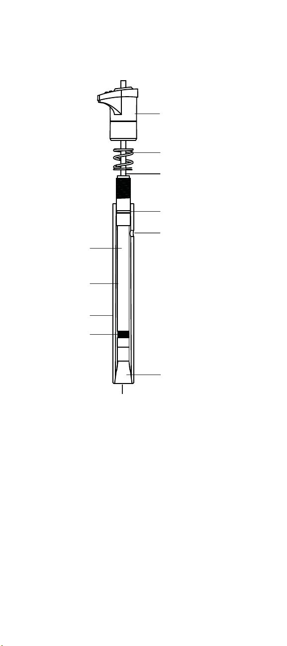
inner
body
filling solution
chamber
outer body
reference
element
cap
spring
cable
O-ring
filling hole
inner cone
sensing crystal
Figure 1
9609BNWP Fluoride Combination Electrode
2 Fluoride Ion Selective Electrode User Guide
Page 7

Required Equipment
1. Thermo Scientifi c Orion ISE meter, such as the Orion 4-Star
pH/ISE meter, Orion 5-Star pH/ISE/DO/conductivity meter
or Orion DUAL STAR meter.
Fluoride electrodes can be used on any ISE meter with
a BNC connection. The electrodes can also be used on
meters with a variety of inputs when an adapter cable is
used. Visit www.thermoscientifi c.com/water for details.
2. Thermo Scientifi c Orion fl uoride ion selective electrode.
The 9409BN and 9409SC fl uoride half-cell electrodes
require a separate reference electrode,
Cat. No. 900100.
3. Magnetic stirrer or Orion stirrer probe, Cat. No. 096019.
The Orion stirrer probe can be used with 3-Star, 4-Star, 5Star benchtop meters, and Dual Star meter.
4. Volumetric fl asks, graduated cylinders and beakers.
Plastic labware is highly recommended for fl uoride analysis.
5. Distilled or deionized water.
6. Fluoride electrode fi lling solution.
Use Optimum Results A fi lling solution, Cat. No. 900061,
for the 9609BNWP fl uoride electrodes.
Use single junction reference electrode fi lling solution,
Cat. No. 900001, for the reference electrode used with the
9409BN and 9409SC fl uoride electrodes.
7. Fluoride calibration standards.
Cat. No. Description
940906 0.1 M NaF, 475 mL bottle
940907 100 ppm F¯, 475 mL bottle
040908 10 ppm F¯ with TISAB II, 475 mL bottle
040907 2 ppm F¯ with TISAB II, 475 mL bottle
040906 1 ppm F¯ with TISAB II, 475 mL bottle
3Fluoride Ion Selective Electrode User Guide
Page 8

8. Total Ionic Strength Adjustment Buffer (TISAB),
which provides a constant background ionic strength,
decomplexes fl uoride ions and adjusts the solution pH.
Cat. No. Description
940909 TISAB II, 3.8 L bottle
940999 TISAB II, 4 x 3.8 L bottle
940911 TISAB III concentrate, 475 mL bottle
Low-Level TISAB
For use when measuring in samples containing less than 0.4
ppm (2 x 10
as iron or aluminum are present.
To prepare low level TISAB: Place 500 mL of distilled water in
a 1 liter beaker. Add 57 mL of glacial acetic acid and 58 g of
reagent grade sodium chloride to the beaker. Place the beaker
in a water bath for cooling. Immerse a calibrated pH electrode
into the solution and slowly add 5 M NaOH until the pH is
between 5.0 and 5.5. Cool the solution to room temperature.
Pour the solution into a 1 liter volumetric fl ask and dilute to the
fl ask mark with distilled water. All reagents must be as pure as
possible to keep the fl uoride level low in the buffer.
Use as directed for TISAB II; combine equal volumes of low level
TISAB and sample or standard before taking any measurements.
-5
M) fl uoride and no fl uoride complexing agents such
TISAB IV
TISAB IV will complex more than 100 ppm of iron or aluminum
in the presence of 1 ppm fl uoride. A measurement of 1 ppm
fl uoride will be in error by 5% in the presence of 200 ppm iron
or aluminum.
To prepare TISAB IV: Place 500 mL of distilled water in a 1 liter
volumetric fl ask. Add 84 mL of concentrated HCl (36 to 38 %),
242 g TRIS (hydroxymethyl) aminomethane and 230 g sodium
tartrate (Na
and cool the solution to room temperature. Dilute to the fl ask
mark with distilled water.
-2H2O) to the fl ask. Stir to dissolve the solids
2C4H406
Use as directed for TISAB II; combine equal volumes of TISAB IV
and sample or standard before measurements.
4 Fluoride Ion Selective Electrode User Guide
Page 9

Electrode Setup
Electrode Preparation
9409BN and 9409SC Fluoride Half-Cell Electrode– Remove the
protective shipping cap from the sensing element and save the
cap for storage.
900100 Single Junction Reference Electrode– Prepare the
reference electrode according to the reference electrode user
guide. Fill the reference electrode with single junction reference
fi lling solution, Cat. No. 900001.
9609BNWP Fluoride Combination Electrode– Remove the
protective shipping cap from the sensing element and save
the cap for storage. Fill the electrode with Optimum Results A
fi lling solution, Cat. No. 900061.
Note: Optimum Results A fi lling solution minimizes junction
potential issues and fl uoride contamination in the sample. The
use of any other fi lling solution will void the electrode warranty.
Electrode Filling Instructions
1. Lift the fl ip spout on the fi lling solution bottle to a vertical
position.
2. Insert the spout into the fi lling hole on the outer body of the
electrode and add a small amount of fi lling solution to the
reference chamber. Invert the electrode to moisten the top
O-ring and then return the electrode to the upright position.
3. Hold the electrode body with one hand and use your thumb
to push down on the electrode cap to allow a few drops of
fi lling solution to drain out of the electrode.
4. Release the electrode cap. If the sleeve does not return to
its original position, check if the O-ring is moist and repeat
steps 2-4 until the sleeve returns to the original position.
5. Add fi lling solution to the electrode up to the fi lling hole.
Note: Add fi lling solution each day before using the electrode.
The fi lling solution level should be at least one inch above the
level of sample in the beaker to ensure a proper fl ow rate. The
fi ll hole should always be open when taking measurements.
5Fluoride Ion Selective Electrode User Guide
Page 10

Checking Electrode Operation (Slope)
These are general instructions that can be used with most
meters to check the electrode operation. Refer to the meter
user guide for more specifi c information.
This procedure measures electrode slope. Slope is defi ned
as the change in millivolts observed with every tenfold change
in concentration. Obtaining the slope value provides the best
means for checking electrode operation.
1. If the electrode has been stored dry, prepare the electrode
as described in the Electrode Preparation section.
2. Connect the electrode to the meter. Set the meter to the
mV mode.
3. Place 50 mL of distilled water and 50 mL of TISAB II (Lowlevel TISAB or TISAB IV) into a 150 mL beaker. Stir the
solution thoroughly.
If using TISAB III, place 90 mL of distilled water and
10 mL of TISAB III into a 150 mL beaker. Stir the solution
thoroughly.
4. Rinse the electrode with distilled water and place the
electrode into the solution prepared in step 3.
5. Select either a 0.1 M sodium fl uoride or 100 ppm fl uoride
standard. Pipette 1 mL of the standard into the beaker and
stir thoroughly. When a stable reading is displayed, record
the electrode potential in millivolts.
6. Pipette 10 mL of the same standard into the same beaker
and stir thoroughly. When a stable reading is displayed,
record the electrode potential in millivolts.
7. There should be a 54 to 60 mV difference between the
two millivolt readings when the solution temperature is
between 20 to 25 ˚C. If the millivolt potential is not within
this range, refer to the Troubleshooting section.
6 Fluoride Ion Selective Electrode User Guide
Page 11

Measurement Units
Fluoride concentration can be measured in moles per liter (M),
parts per million (ppm) or any convenient concentration unit.
Table 1
Concentration Unit Conversion Factors
Moles/Liter (M) ppm
1.0 19000
-1
10
-2
10
-3
10
-4
10
1900
190
19
1. 9
Sample Requirements
The epoxy body of the fl uoride electrode is resistant to damage
by inorganic solutions. The electrode may be used intermittently
in solutions that contain methanol or acetone. Contact Technical
Support for information on using the electrode for specifi c
applications.
Samples and standards should be at the same temperature.
The solution temperature must be less than 100 °C.
In all analytical procedures, TISAB must be added to all samples
and standards before measurements are taken.
7Fluoride Ion Selective Electrode User Guide
Page 12

Measuring Hints
• Add 50 mL of TISAB II (Low-level TISAB or TISAB IV) to
every 50 mL of standard or sample. Add 10 mL of TISAB III
to every 90 mL standard or sample. Once TISAB II (Lowlevel TISAB or TISAB IV) or TISAB III is selected, it should be
added to all samples and standards so the dilution ratio of
TISAB to solution remains the same.
• Stir all standards and samples at a uniform rate.
• Always use fresh standards for calibration.
• Always rinse the electrode with deionized water between
measurements and shake the electrode to remove the
water and prevent sample carryover. Do not wipe or rub
the electrode sensing element.
• Allow all standards and samples to come to the same
temperature for precise measurements.
• Place a piece of insulating material, such as Styrofoam or
cardboard, between the magnetic stirrer and beaker to prevent
measurement errors from the transfer of heat to the sample.
• Verify the electrode calibration every two hours by placing
the electrode in a fresh aliquot of the least concentrated
standard used for calibration. If using more than 2
standards, use a mid-level standard. If the value has
changed by more than 2%, recalibrate the electrode.
• After immersing the electrode in a solution, check the
electrode sensing surface for air bubbles and remove air
bubbles by reimmersing the electrode in the solution.
• For high ionic strength samples, prepare standards with
a background composition similar to the sample or use
manual known addition procedure or a Dual Star meter.
• Adjust highly acidic or highly basic solutions to pH 5 - 6
before adding TISAB.
• Remove the fi lling hole cover during measurements to
ensure a uniform fl ow of fi lling solution.
• If the electrode is used in dirty or viscous samples or the
electrode response becomes sluggish, empty the electrode
completely, hold the junction open and fl ush the junction
with deionized water. Empty any water from the electrode
and refi ll it with fresh fi lling solution. Press down on the
electrode cap to let a few drops of the fi lling solution fl ow
out of the electrode and then replenish any lost solution.
8 Fluoride Ion Selective Electrode User Guide
Page 13

Electrode Storage
9409BN and 9409SC Fluoride Half-Cell Electrode
The fl uoride half-cell electrodes should be rinsed thoroughly
with distilled water and stored dry in the air at all times. When
storing the electrode for long periods of time, cover the sensing
element with the protective shipping cap.
900100 Single Junction Reference Electrode
The single junction reference electrode may be stored in the
single junction electrode fi lling solution, Cat. No. 900001,
between sample measurements and up to one week. A 0.01 M
or 100 ppm fl uoride standard is also an acceptable storage
solution. The fi lling solution inside the electrode should not be
allowed to evaporate, as crystallization will result.
For storage longer than one week, drain the reference electrode,
fl ush the inside with distilled water and store the electrode dry.
9609BNWP Fluoride Combination Electrode
For storage between measurements and up to one week, store
the electrode in electrode fi ll solution, Cat. No. 900061, with
fl uoride added. The fl uoride concentration of the storage solution
should be close to least concentrated fl uoride calibration
standard. Do not add TISAB to the storage solution. The fi lling
solution should not be allowed to evaporate, as crystallization
will result. If fi ll solution is unavailable, store in 2 M potassium
nitrate with fl uoride added.
For storage longer than one week, drain the electrode. Flush
the chamber with distilled water. Disassemble the electrode as
described in the electrode maintenance section. Rinse the inner
sleeve with distilled water and blot dry with a Kimwipe. Do not
touch the reference element other than to blot dry. Let air dry
and then reassemble for storage. Use the protective shipping
cap to cover the sensing element.
9Fluoride Ion Selective Electrode User Guide
Page 14

Electrode Maintenance
Polishing the Sensing Surface of the Fluoride Combination
Electrodes and Fluoride Half-Cell Electrodes
The sensing surface of the fl uoride electrode might need
restoration over time as deposits coat the sensing surface. The
sensing crystal can be restored using the following procedure.
Toothpaste that contains fl uoride will be needed for this
procedure.
1. Dispense a small amount of fl uoridated toothpaste on
a kimwipe. Add a few drops of deionized water. A soft
toothbrush can also be used in placed of a kimwipe.
2. Rub the toothpaste on the sensing element on the bottom
of the electrode in a circular motion for around one minute.
3. Rinse the electrode thoroughly with DI water, fl ush the
electrode fi ll solution out (if using a combination fl uoride
electrode) by pressing on the cap of the electrode) then
refi ll with fresh fi ll solution.
4. Soak the electrode in 100 ppm fl uoride standard for 2 hours.
Flushing the 9609BNWP and 900100 Single Junction
Reference Electrode
If the area between the electrode sleeve and inner cone
becomes clogged with sample or precipitate, fl ush the area with
fi lling solution or distilled water.
1. Hold the electrode body with one hand and use your thumb
to push down on the electrode cap to drain the chamber.
Push down on the cap until all the fi lling solution is drained
from the chamber.
2. Fill the electrode with distilled water and then push down
on the cap until all the water is drained from the chamber.
3. Fill the electrode with fresh fi lling solution up to the fi ll
hole. Push down on the cap to allow a few drops of fi lling
solution to drain out of the electrode and then refi ll any lost
fi lling solution.
10 Fluoride Ion Selective Electrode User Guide
Page 15

Disassembling the Fluoride Combination Electrodes and
Single Junction Reference Electrode
Note: Disassembly is usually not required and should not be
done unless a thorough cleaning is required.
1. Tip the electrode so the fi lling solution moistens the O-ring
on the electrode body. Hold the electrode body with one
hand and use your thumb to push down on the electrode
cap to drain the chamber.
2. Unscrew the cap counter clock-wise and then slide the cap
and the spring up the cable.
3. Hold the outer sleeve with one hand and fi rmly push down
on the threaded portion with the thumb and forefi nger to
separate the inner body from the sleeve.
4. Grasp the cone with a clean, lint-free tissue and withdraw
the body from the sleeve using a gentle twisting motion.
Do not touch the reference electrode element (coiled wire
in combination electrode, pellet in single junction reference)
above the cone, it will damage to the reference element.
Rinse the outside of the electrode body and the entire
sleeve with distilled water. Blot dry with a Kimwipe and
allow to air dry if needed.
Reassembling the Fluoride Combination Electrodes and
Single Junction Reference Electrode
1. Moisten the O-ring on the electrode body with a drop of
fi lling solution. Insert the screw-thread end of the electrode
body into the tapered, ground end of the sleeve.
2. Push the body into the sleeve using a gentle twisting
motion until the bottom surface of the inner cone is fl ush
with the tapered end of the sleeve.
3. Place the spring onto the electrode body and screw on the
cap. Refi ll the electrode with fi lling solution.
11Fluoride Ion Selective Electrode User Guide
Page 16

12 Fluoride Ion Selective Electrode User Guide
Page 17

Analytical Techniques
A variety of analytical techniques are available to the analyst.
The following is a description of these techniques.
Direct Calibration is a simple procedure for measuring a
large number of samples. Only one meter reading is required
for each sample. Calibration is performed using a series of
standards. The concentration of the samples is determined by
comparison to the standards. TISAB is added to all solutions to
ensure that samples and standards have similar ionic strength.
Incremental Techniques provide a useful method for measuring
samples, since calibration is not required. As in direct
calibration, any convenient concentration unit can be used. The
different incremental techniques are described below. They can
be used to measure the total concentration of a specifi c ion in
the presence of a large (50-100 times) excess of complexing
agents.
• Known Addition is useful for measuring dilute samples,
checking the results of direct calibration (when no
complexing agents are present), or measuring the total
concentration of an ion in the presence of an excess
complexing agent. The electrode is immersed in the
sample solution and an aliquot of a standard solution
containing the measured species is added to the sample
when performing single known addition. From the change
in potential before and after the addition, the original
sample concentration is determined. Double known
addition is recommended for complex sample matrices.
• Known Subtraction is useful as a quick version of
a titration, or for measuring species for which stable
standards do not exist. It is necessary to know the
stoichiometric ratio between standard and sample. For
known subtraction, an electrode sensing the sample
species is used. Stable standards of a species reacting
completely with the sample in a reaction of known
stoichiometry are necessary.
• Analate Addition is often used to measure soluble solid
samples, viscous samples, small or very concentrated
samples, to diminish the effects of complex sample
matrices, or to diminish the effects of varying sample
temperatures. This method is not suitable for dilute or low
concentration samples. Total concentration is measured
even in the presence of complexing agents. The electrode
is immersed in a standard solution containing the ion to
be measured and an aliquot of the sample is added to the
standard. The original sample concentration is determined
from the change in potential before and after the addition.
13Fluoride Ion Selective Electrode User Guide
Page 18

• Analate Subtraction is used in the measurement of ions
for which no ion-selective electrode exists. The electrode is
immersed in a reagent solution that contains a species that
the electrode senses, and that reacts with the sample. It
is useful when sample size is small, or samples for which
a stable standard is diffi cult to prepare, and for viscous
or very concentrated samples. The method is not suited
for very dilute samples. It is also necessary to know the
stoichiometric ratio between standard and sample.
• Titrations are quantitative analytical techniques for
measuring the concentration of a species by incremental
addition of a reagent (titrant) that reacts with the sample
species. Sensing electrodes can be used for determination
of the titration end point. Ion selective electrodes are
useful as end point detectors, because they are unaffected
by sample color or turbidity. Titrations are approximately
10 times more precise than direct calibration, but are more
time-consuming.
14 Fluoride Ion Selective Electrode User Guide
Page 19

Typical Calibration Curve
In the direct calibration procedure, a calibration curve is
constructed either in the meter memory or in an electronic
spreadsheet and graphing the log of the fl uoride concentration
against the millivolt value readings. Electrode potentials of
standard solutions are measured and plotted on the linear
axis against their concentrations on the log axis. In the linear
regions of the curves, only two standards are needed to
determine a calibration curve. In non-linear regions, more points
must be taken. These direct calibration procedures are given for
concentrations in the region of linear electrode response. Low
level measurement procedures are given in the next section for
measurements in the non-linear region.
electrode
-60
potential
(mV)
-40
-20
100
120
140
160
180
0
20
40
60
80
0.1
-54 to -60 mV
- 5
10
10-fold change
ppm fluoride as F
1 10 100 1000
- 4
10
- 3
10
- 2
10
-
- 1
10
molarity
Figure 2 Typical Calibration Curve
15Fluoride Ion Selective Electrode User Guide
Page 20

Direct Calibration
Setup
1. Prepare the electrode as described in the Electrode
Preparation section. If using the 9409BN or 9409SC half-
cell fl uoride electrode with the 900100 reference electrode,
fi ll the reference electrode with Cat. No. 900001. If using
the 9609BNWP combination fl uoride electrode, fi ll the
electrode with Cat. No. 900061.
2. Connect the electrodes to the meter.
3. Prepare at least two standards that bracket the expected
sample range and differ in concentration by a factor of ten.
Standards can be prepared in any concentration unit to suit
the particular analysis requirement. All standards should
be at the same temperature as the samples. For details on
temperature effects on electrode performance, refer to the
Temperature Effects section.
Serial Dilutions
Serial dilution is the best method for the preparation of
standards. Serial dilution means that an initial standard is
diluted, using volumetric glassware, to prepare a second
standard solution. The second standard is similarly diluted to
prepare a third standard, and so on, until the desired range of
standards has been prepared.
1. To prepare a 10-2 M NaF standard (190 ppm fl uoride)–
Pipette 10 mL of the 0.1 M NaF standard into a 100 mL
volumetric fl ask. Dilute to the mark with deionized water
and mix well.
-3
2. To prepare a 10
Pipette 10 mL of the 10
M NaF standard (19 ppm fl uoride)–
-2
M NaF standard into a 100 mL
volumetric fl ask. Dilute to the mark with deionized water
and mix well.
3. To prepare a 10-4 M NaF standard (1.9 ppm fl uoride)–
Pipette 10 mL of the 10
-3
M NaF standard into a 100 mL
volumetric fl ask. Dilute to the mark with deionized water
and mix well.
16 Fluoride Ion Selective Electrode User Guide
Page 21

To prepare standards with a different concentration use the
following formula:
* V1 = C2 * V
C
1
2
where
C
= concentration of original standard
1
V1 = volume of original standard
C2 = concentration of standard after dilution
V2 = volume of standard after dilution
For example, to prepare 100 mL of a 1 ppm fl uoride standard
from a 100 ppm fl uoride standard:
C1 = 100 ppm fl uoride
= unknown
V
1
C
= 1 ppm fl uoride
2
V2 = 100 mL
100 ppm * V
V
= (1 ppm * 100 mL) / 100 ppm = 1 mL
1
= 1 ppm * 100 mL
1
To make the 1 ppm fl uoride standard, pipette 1 mL of the
100 ppm fl uoride standard into a 100 mL volumetric fl ask.
Dilute to the mark with deionized water and mix well.
Fluoride Standards with TISAB II
The 10 ppm fl uoride with TISAB II standard, Cat. No. 040908;
2 ppm fl uoride with TISAB II standard, Cat. No. 040907; and
1 ppm fl uoride with TISAB II standard, Cat. No. 040906, do not
require the addition of TISAB II because TISAB II has already
been added.
Add 50 mL of TISAB II to every 50 mL of sample to keep the
dilution ration of TISAB II to solution consistent for the standards
and samples.
17Fluoride Ion Selective Electrode User Guide
Page 22

Direct Calibration Using a Meter with an ISE Mode
Note: See the meter user guide for more specifi c information.
1. Measure 50 mL of the less concentrated standard and
50 mL of TISAB II and pour into a 150 mL beaker. Stir the
solution thoroughly.
2. Rinse the electrode with deionized water, blot dry and place
into the beaker with the less concentrated standard. Wait
for a stable reading and then adjust the meter to display the
value of the standard, as described in the meter user guide.
3. Measure 50 mL of the more concentrated standard and
50 mL of TISAB II and pour into a second 150 mL beaker.
Stir the solution thoroughly.
4. Rinse the electrode with deionized water, blot dry and place
into the beaker with the more concentrated standard. Wait
for a stable reading and then adjust the meter to display
the value of the second standard, as described in the meter
user guide.
5. Record the resulting slope value. The slope should be
between -54 to -60 mV when the standards are between
20-25 ˚C. When using a Thermo Scientifi c meter with the
Autoblank function enabled, the absolute value of the slope
should be greater than 54 mV.
6. Measure 50 mL of the sample and 50 mL of TISAB II (or
either low-level TISAB or TISAB IV) and pour into a clean 150
mL beaker. Stir the solution thoroughly.
7. Rinse the electrode with deionized water, blot dry and place
into the sample. The concentration of the sample will be
displayed on the meter.
Note: If using TISAB III, add 5 mL of TISAB III to the 50 mL of
standard or sample in step 1, step 3 and step 6.
18 Fluoride Ion Selective Electrode User Guide
Page 23

Direct Calibration Using a Meter with a Millivolt Mode
1. Adjust the meter to measure mV.
2. Measure 50 mL of the less concentrated standard and
50 mL of TISAB II and add the standard and TISAB II to a
150 mL beaker. Stir the solution thoroughly.
3. Rinse the electrode with deionized water, blot dry and place
into the beaker with the less concentrated standard. When
a stable reading is displayed, record the mV value and
corresponding standard concentration.
4. Measure 50 mL of the more concentrated standard and
50 mL of TISAB II and add the standard and TISAB II to a
second 150 mL beaker. Stir the solution thoroughly.
5. Rinse the electrode with deionized water, blot dry and
place into the beaker with the more concentrated standard.
When a stable reading is displayed, record the mV value
and corresponding standard concentration.
6. Using a calculator or electronic spreadsheet, prepare
a calibration curve by graphing the log of the fl uoride
concentration against the millivolt value readings.
7. Measure 50 mL of the sample and 50 mL of TISAB II and
add the sample and TISAB II to a clean 150 mL beaker. Stir
the solution thoroughly.
8. Rinse the electrode with deionized water, blot dry and place
into the beaker. When a stable reading is displayed, record
the mV value.
9. Using the calibration curve prepared in step 6, determine
the unknown concentration of the sample.
Note: If using TISAB III, add 5 mL of TISAB III to the 50 mL of
standard or sample in step 2, step 4 and step 7.
19Fluoride Ion Selective Electrode User Guide
Page 24

Low-Level Measurements
These procedures are for low ionic strength solutions that do
not contain fl uoride complexing agents and have a fl uoride
concentration of less than 2 x 10⁻⁵ M (0.38 ppm). For solutions
low in fl uoride but high in total ionic strength, perform the same
procedure by preparing a calibrating solution with a composition
similar to the sample. Accurate measurement requires that the
following conditions be met:
• Adequate time must be allowed for electrode
stabilization. Longer response time will be needed at
low-level measurements.
• Stir all standards and samples at a uniform rate.
• Low-level TISAB is recommended for samples and
standards.
Low-Level Setup
1. Prepare the electrode as described in the Electrode
Preparation section.
2. Connect the electrode to the meter. Set the meter to
read mV.
3. Prepare the low-level TISAB. Refer to the Required
Equipment section for instructions. Use low-level TISAB
for low-level measurements only.
4. Prepare 100 mL of standard solution. Dilute the 100 ppm
fl uoride standard, Cat. No. 940907, to 10 ppm or dilute the
0.1 M NaF standard, Cat. No. 940906, to 10-3 M.
5. Add 100 mL of the low-level TISAB to the 100 mL of
standard.
Low-Level Calibration and Measurement Using a Thermo
Scientifi c Orion ISE Meter with Autoblank Capability
1. When using a Thermo Scientifi c Orion ISE meter in
ISE mode with Autoblank mode enabled, a three point
calibration is usually suffi cient to prepare an accurate
calibration curve at low levels.
2. Choose three calibration points to bracket the
concentrations of interest. It is advised to choose points
which are not more than a factor 10 between each point, for
example, 0.05, 0.5, and 5 mg/L fl uoride standards.
20 Fluoride Ion Selective Electrode User Guide
Page 25

3. Prepare the standards as described in the Direct Calibration
section of this user guide. Prepare calibration standards for
testing by mixing a portion of the standard with an equal
portion of low level TISAB in a non-glass beaker. Stir the
solution.
4. Ensure that the Autoblank mode is enabled in the meter
setup mode.
5. Rinse the electrode with deionized water, blot dry and
place into the beaker with the least concentration standard.
While stirring the solution, select the meter calibration
mode and wait for a stable reading. Adjust the meter to
display the value of the standard, as described in the meter
user guide.
6. Repeat step 5 for the second and third standards and
complete the calibration, as described in the meter user guide.
7. Record the resulting slope value. The absolute value of
millivolt difference should be greater than 54 mV.
8. Measure equal amounts of the sample and low level TISAB
into a non-glass beaker. Stir the solution.
9. Rinse the electrode with deionized water, blot dry and place
into the beaker with the prepared sample. Continue stirring
the solution and wait for a stable reading. The concentration
of the sample will be displayed on the meter.
21Fluoride Ion Selective Electrode User Guide
Page 26

Low-Level Calibration and Measurement When Using a Meter
with Millivolt Mode
1. Measure 50 mL of deionized water and 50 mL of low-level
TISAB and add to a 150 mL beaker.
2. Rinse the electrode with deionized water and place into
beaker. Stir the solution thoroughly.
3. Add increments of the 10 ppm or 10-3 M fl uoride standard
mixed with low-level TISAB to the beaker using the steps
outlined in Table 2. Record the stable millivolt reading after
each increment.
4. Using a calculator or or electronic spreadsheet, prepare
a calibration curve by graphing the log of the fl uoride
concentration against the millivolt value readings. Prepare a
new calibration curve with fresh standards each day.
5. Measure 50 mL of sample and 50 mL of low-level TISAB
and add to a clean 150 mL beaker. Rinse the electrode with
deionized water, blot dry and place into the sample.
6. Stir the solution thoroughly. When a stable reading is
displayed, record the mV value.
7. Determine the sample concentration corresponding to the
measured potential from the low-level calibration curve.
Table 2 Calibration Curve For Low-Level Measurements
Additions of standard (with low-level TISAB) to 50 mL distilled
water and 50 mL low-level TISAB solution.
Concentration
Step Pipette
Size
1 1 mL 0.1 mL 0.01 1 x 10
2 1 mL 0.1 mL 0.02 2 x 10
3 1 mL 0.2 mL 0.04 4 x 10
4 1 mL 0.2 mL 0.06 6 x 10
5 1 mL 0.4 mL 0.10 1 x 10
6 2 mL 2.0 mL 0.29 2.9 x 10
7 2 mL 2.0 mL 0.48 4.8 x 10
Volume
Added
ppm M
-6
-6
-6
-6
-5
-5
-5
22 Fluoride Ion Selective Electrode User Guide
Page 27

Single Known Addition
Known addition is a convenient technique for measuring samples
because no calibration curve is required. It can be used to
verify the results of a direct calibration or to measure the total
concentration of an ion in the presence of a large excess of a
complexing agent. The sample potential is measured before and
after addition of a standard solution. Accurate measurement
requires that the following conditions be met:
• Concentration should approximately double as a result of
the addition.
• Sample concentration should be known to within a factor
of three.
• Either no complexing agent or a large excess of the
complexing agent may be present.
• The ratio of the uncomplexed ion to complexed ion must
not be changed by addition of the standard.
• All samples and standards should be at the same
temperature.
23Fluoride Ion Selective Electrode User Guide
Page 28

Single Known Addition Setup
1. Prepare the electrode as described in the Electrode
Preparation section.
2. Connect the electrode to the meter.
3. Prepare a standard solution that will cause the fl uoride
concentration of the sample to double when added to the
sample solution. Refer to Table 3 for guidelines.
4. Determine the electrode slope by performing the procedure
in the Checking Electrode Operation (Slope) section.
5. Rinse the electrode with deionized water.
Table 3 Guideline For Known Addition
Volume of Addition Concentration of Standard
1 mL 100 times sample concentration
5 mL 20 times sample concentration
10 mL* 10 times sample concentration
* Most convenient volume to use
24 Fluoride Ion Selective Electrode User Guide
Page 29

Single Known Addition Using a Meter with a Known
Addition Mode
Note: See the meter user guide for more specifi c information.
1. Set up the meter to measure in the known addition mode.
2. Measure 50 mL of the sample and 50 mL of TISAB II or
5 mL of TISAB III and add to a beaker. Rinse the electrode
with deionized water and place it into the sample solution.
Stir the solution thoroughly.
3. When a stable reading is displayed, set the meter as
described in the meter user guide, if required.
4. Pipette the appropriate amount of the standard solution into
the beaker. Stir the solution thoroughly.
5. When a stable reading is displayed, record the sample
concentration.
Single Known Addition Using a Meter with a Millivolt Mode
1. Set the meter to relative millivolt mode. If a relative
millivolt mode is not available, use the millivolt mode.
2. Measure 50 mL of sample and 50 mL of TISAB II or 5 mL
of TISAB III and add to a 150 mL beaker. Stir the solution
thoroughly.
3. Rinse the electrode with deionized water, blot dry and place
into the beaker. When a stable reading is displayed, set the
meter to read 0.0 mV. If the reading cannot be adjusted to
0.0 mV, record the actual mV value.
4. Pipette the appropriate amount of standard solution into the
beaker. Stir the solution thoroughly.
5. When a stable reading is displayed, record the mV value.
If the meter could not be set to 0.0 mV in step 3, subtract
the fi rst reading from the second reading to calculate ΔE.
Note: Double known addition method is outlined in the Dual
Star meter manual.
25Fluoride Ion Selective Electrode User Guide
Page 30

6. Use Table 4 to fi nd the Q value that corresponds to the
change in potential, ΔE. To determine the original sample
concentration, multiply Q by the concentration of the added
standard:
C
sample
= Q * C
standard
where
C
C
= standard concentration
standard
= sample concentration
sample
Q = value from Table 4
The table of Q values is calculated for a 10% volume change.
The equation for the calculation of Q for different slopes and
volume changes is given below.
Q = (p * r) / {[(1 + p) * 10
ΔE/S
]-1}
where
Q = value from Table 4
ΔE = E2 - E
1
S = slope of the electrode
p = volume of standard / volume of sample and ISA
r = volume of sample and ISA / volume of sample
26 Fluoride Ion Selective Electrode User Guide
Page 31

Table 4 Q Values for a 10% Volume Change
Slopes (in column heading) are in units of mV/decade.
ΔE Q Concentration Ratio
Monovalent 57.2 58.2 59.2 60.1
5.0 0.2894 0.2933 0.2972 0.3011
5.2 0.2806 0.2844 0.2883 0.2921
5.4 0.2722 0.2760 0.2798 0.2835
5.6 0.2642 0.2680 0.2717 0.2754
5.8 0.2567 0.2604 0.2640 0.2677
6.0 0.2495 0.2531 0.2567 0.2603
6.2 0.2436 0.2462 0.2498 0.2533
6.4 0.2361 0.2396 0.2431 0.2466
6.6 0.2298 0.2333 0.2368 0.2402
6.8 0.2239 0.2273 0.2307 0.2341
7. 0 0.2181 0.2215 0.2249 0.2282
7. 2 0.2127 0.2160 0.2193 0.2226
7. 4 0.2074 0.2107 0.2140 0.2172
7. 6 0.2024 02.056 0.2088 0.2120
7. 8 0.1975 0.2007 0.2039 0.2023
8.0 0.1929 0.1961 0.1992 0.2023
8.2 0.1884 0.1915 0.1946 0.1977
8.4 0.1841 0.1872 0.1902 0.1933
8.6 0.1800 0.1830 0.1860 0.1890
8.8 0.1760 0.1790 0.1820 0.1849
9.0 0.1722 0.1751 0.1780 0.1809
9.2 0.1685 0.1714 0.1742 0.1771
9.4 0.1649 0.1677 0.1706 0.1734
9.6 0.1614 0.1642 0.1671 0.1698
9.8 0.1581 0.1609 0.1636 0.1664
10.0 0.1548 0.1576 0.1603 0.1631
10.2 0.1517 0.1544 0.1571 0.1598
10.4 0.1487 0.1514 0.1540 0.1567
10.6 0.1458 0.1484 0.1510 0.1537
10.8 0.1429 0.1455 0.1481 0.1507
11. 0 0.1402 0.1427 0.1453 0.1479
11. 2 0.1375 0.1400 0.1426 0.1451
11. 4 0.1349 0.1374 0.1399 0.1424
11. 6 0.1324 0.1349 0.1373 0.1398
11. 8 0.1299 0.1324 0.1348 0.1373
12.0 0.1276 0.1300 0.1324 0.1348
12.2 0.1253 0.1277 0.1301 0.1324
12.4 0.1230 0.1254 0.1278 0.1301
12.6 0.1208 0.1232 0.1255 0.1278
12.8 0.1187 0.1210 0.1233 0.1256
13.0 0.1167 0.1189 0.1212 0.1235
13.2 0.1146 0.1169 0.1192 0.1214
13.4 0.1127 0.1149 0.1172 0.1194
13.6 0.1108 0.1130 0.1152 0.1174
13.8 0.10 89 0 .1111 0 .1133 0.1155
14.0 0.1071 0.1093 0.1114 0.1136
14.2 0.1053 0.1075 0.1096 0.1118
14.4 0.1036 0.1057 0.1079 0.1100
14.6 0.1019 0.1040 0.1061 0.1082
14.8 0.1003 0.1024 0.1045 0.1065
15.0
15.5 0.0949 0.0969 0.0989 0.1009
16.0 0.0913 0.0932 0.0951 0.0971
16.5 0.0878 0.0897 0.0916 0.0935
17.0 0.0846 0.0865 0.0883 0.0901
0.0987 0.1008 0.1028 0.1048
27Fluoride Ion Selective Electrode User Guide
Page 32

ΔE Q Concentration Ratio
Monovalent 57.2 58.2 59.2 60.1
17.5 0.0815 0.0833 0.0852 0.0870
18.0 0.0786 0.0804 0.0822 0.0839
18.5 0.0759 0.0776 0.0793 0.0810
19.0 0.0733 0.0749 0.0766 0.0783
19.5 0.0708 0.0724 0.0740 0.0757
20.0 0.0684 0.0700 0.0716 0.0732
20.5 0.0661 0.0677 0.0693 0.0708
21.0 0.0640 0.0655 0.0670 0.0686
21.5 0.0619 0.0634 0.0649 0.0664
22.0 0.0599 0.0614 0.0629 0.0643
22.5 0.0580 0.0595 0.0609 0.0624
23.0 0.0562 0.0576 0.0590 0.0605
23.5 0.0545 0.0559 0.0573 0.0586
24.0 0.0528 0.0542 0.0555 0.0569
24.5 0.0512 0.0526 0.0539 0.055
25.0 0.0497 0.0510 0.0523 0.0536
25.5 0.0482 0.0495 0.0508 0.0521
26.0 0.0468 0.0481 0.0493 0.0506
26.5 0.0455 0.0467 0.0479 0.0491
27.0 0.0442 0.0454 0.0466 0.0478
27.5 0.0429 0.0441 0.0453 0.0464
28.0 0.0417 0.0428 0.0440 0.0452
28.5 0.0405 0.0417 0.0428 0.0439
29.0 0.0394 0.0405 0.0416 0.0427
29.5 0.0383 0.0394 0.0405 0.0416
30.0 0.0373 0.0383 0.0394 0.0405
31.0 0.0353 0.0363 0.0373 0.0384
32.0 0.0334 0.0344 0.0354 0.0364
33.0 0.0317 0.0326 0.0336 0.0346
34.0 0.0300 0.0310 0.0319 0.0328
35.0 0.0285 0.0294 0.0303 0.0312
36.0 0.0271 0.0280 0.0288 0.0297
37.0 0.0257 0.0266 0.0274 0.0283
38.0 0.0245 0.0253 0.0261 0.0269
39.0 0.0233 0.0241 0.0249 0.0257
40.0 0.0222 0.0229 0.0237 0.0245
41.0 0.0211 0.0218 0.0226 0.0233
42.0 0.0201 0.0208 0.0215 0.0223
43.0 0.0192 0.0199 0.0205 0.0212
44.0 0.0183 0.0189 0.0196 0.0203
45.0 0.0174 0.0181 0.0187 0.0194
46.0 0.0166 0.0172 0.0179 0.0185
47.0 0.0159 0.0165 0.0171 0.0177
48.0 0.0151 0.0157 0.0163 0.0169
49.0 0.0145 0.0150 0.0156 0.0162
50.0 0.0138 0.0144 0.0149 0.0155|
51.0 0.0132 0.0137 0.0143 0.0148
52.0 0.0126 0.0131 0.0136 0.0142
53.0 0.0120 0.0125 0.0131 0.0136
54.0 0.0115 0.0120 0.0125 0.0130
55.0
56.0 0.0105 0.0110 0.0115 0.0119
57.0 0.0101 0. 0105 0. 0110 0. 0114
58.0 0. 00 96 0.0101 0 .0105 0. 0109
59.0 0. 00 92 0.0 09 6 0.0101 0.0105
60.0 0. 00 88 0.0 09 2 0.00 96 0.0101
0.0110 0.0115 0.0120 0.0124
28 Fluoride Ion Selective Electrode User Guide
Page 33

Titrations
The electrode makes a highly sensitive endpoint detector for
titrations of a fl uoride-containing sample using lanthanum
nitrate as the titrant. Titrations are more time-consuming than
direct electrode measurements, but results are more accurate
and reproducible. With careful technique, titrations can be
performed that are accurate to ± 0.2% of the total fl uoride
concentration of the sample. The sample should be at least
-3
M total fl uoride in concentration for a good endpoint break.
10
Titrations for fl uoride give low results in the presence of 1%
or more (based on total fl uoride) aluminum, iron, or trivalent
chromium.
The fl uoride electrode can also be used to detect titration
endpoints of samples containing species that react with
fl uoride, such as aluminum, lithium, lanthanum, and thorium.
Contact Technical Support or visit www.thermoscientifi c.com/
water for details.
The following procedure is for the titration of a fl uoride
containing sample with lanthanum nitrate.
1. Prepare a 0.1 M lanthanum nitrate solution by dissolving
43.3 g of reagent-grade La(NO3)3-6H20 in a 1 liter volumetric
fl ask that contains approximately 700 mL of distilled water.
Once the solids are dissolved, fi ll the fl ask to the mark with
distilled water.
2. Standardize the lanthanum nitrate solution by titrating
against a 0.1 M fl uoride standard. Pipette exactly 25 mL of
fl uoride standard into a 250 mL plastic beaker and add
50 mL of distilled water. Place the electrode in the sample.
Stir the solution thoroughly throughout the titration.
3. Using a 10.0 mL burette, add increments of lanthanum
nitrate and plot the electrode potential against mL of
lanthanum nitrate added. The endpoint is the point of
the greatest slope. See Figure 3. Alternately, use a fi rst
derivative calculation or an on-line titration calculator to
determine the end point. Record the endpoint, Vto. Rinse
the electrode and blot dry.
4. Titrate the unknown samples. Pipette exactly 25 mL of
sample into a 250 mL beaker and add 50 mL of distilled
water. Place the electrode in the sample. Stir the solution
thoroughly throughout the titration.
5. Using a 10 mL burette, add increments of lanthanum nitrate
and plot the electrode potential against mL of lanthanum
nitrate added. Determine the endpoint, Vtx.
29Fluoride Ion Selective Electrode User Guide
Page 34

6. Calculate sample concentration, Csx:
CSx = [(Vtx * Vfo) / (Vfx Vto)] * CSo
where
CSx = sample concentration
CSo = fl uoride standard concentration (0.1 M)
Vtx = volume of titrant added in unknown sample titration
at endpoint
Vto = volume of titrant added in standardization titration
at endpoint
Vfx = volume of sample used in sample titration (25 mL)
Vfo = volume of standard used in standardization titration
(25 mL)
-100
-50
0
electrode
potential
(mV)
50
100
titrant volume (mL)
5 10152025
Figure 3 Titration of 0.114 M F¯ with 0.1 M La(NO3)
3
30 Fluoride Ion Selective Electrode User Guide
Page 35

Fluoride in Acid Solutions
In solutions with a pH below 5, hydrogen ions complex a
portion of the fl uoride ions, forming HF or HF
be detected by the fl uoride electrode. To free the complexed
fl uoride, the pH of the solution must be adjusted to the weakly
acidic to weakly basic region before making measurements.
A strong base, such as sodium hydroxide, should not be
used for pH adjustment, since the total ionic strength of the
adjusted samples and standards will vary according to the
original solution pH and the amount of sodium hydroxide
added. Variations in total ionic strength affect the accuracy
of concentration measurements. Dilution of samples and
standards with a large excess of sodium acetate, on the other
hand, will buffer the pH to above 5 and help adjust the total ionic
strength of samples and standards to the same level.
Procedure
1. Prepare a 15% sodium acetate solution. Dissolve reagentgrade sodium acetate (CH
COONa) in distilled water.
3
Prepare a large enough quantity of 15% sodium acetate
solution to dilute all samples and standards.
2. Prepare a background solution that contains all sample
components except fl uoride. Use this solution to prepare
the standards.
3. Prepare standards in the concentration range of the
unknown samples by adding fl uoride to the background
solution. Dilute each standard 10:1 with the sodium acetate
solution (9 parts sodium acetate and 1 part standard).
Prepare fresh standards every two weeks if the standard
contains less than 10 ppm fl uoride. If an ISE (concentration)
meter is used, prepare at least two standards. If a meter
with a mV mode is used, prepare at least three standards.
¯, which cannot
2
4. Calibrate the electrode using the instructions in the
Checking Electrode Operation (Slope) section.
5. Measure the unknown samples: Dilute each unknown
sample 10:1 with sodium acetate before performing taking
measurements (9 parts sodium acetate and 1 part unknown
sample).
Note: In many cases, standards do not need to be prepared
using background solutions. If a standard prepared from the
background solution gives the same reading (after dilution with
sodium acetate) as a standard prepared from pure sodium
fl uoride, then the background solution is unnecessary.
31Fluoride Ion Selective Electrode User Guide
Page 36

Fluoride in Alkaline Solutions
In basic solutions containing low fl uoride content (less than
-4
M at a pH of 9.5 or above), the electrode responds to
10
hydroxide ion as well as to fl uoride ion. The potential reading,
caused by the concentration of both hydroxide and fl uoride ion,
is lower than it would be if fl uoride alone were present. Refer to
the Interferences section.
Adjusting the pH to between 5 and 6 with a 4.0 M buffered
potassium acetate solution eliminates any hydroxide error and
raises the total ionic strength of both samples and standards to
the same value. After both samples and standards are diluted
10:1 with the buffer solution, the fl uoride ion concentration can
be determined in the usual manner.
Procedure
1. Prepare a 4.0 M buffered potassium acetate solution by
diluting 2 parts 6.0 M acetic acid (CH
distilled water and surrounding the reaction with a water
bath. Add 50% KOH solution to the acetic acid slowly,
stirring constantly, until a pH of 5 is reached. Prepare a
large enough quantity of the potassium acetate solution to
dilute all samples and standards.
2. If required, prepare a background solution that contains all
sample components except fl uoride. Use this solution to
prepare the standards.
COOH) with one part
3
3. Prepare standards in the concentration range of the
unknown samples by adding fl uoride to the background
solution. Dilute each standard 10:1 with the potassium
acetate solution (9 parts potassium acetate and 1 part
standard). Prepare fresh standards every two weeks if
the standard contains less than 10 ppm fl uoride. If an
ISE (concentration) meter is used, prepare at least two
standards. If a meter with a mV mode is used, prepare at
least three standards.
4. Calibrate the electrode using the instructions in the
Checking Electrode Operation (Slope) section.
5. Measure the unknown samples: Dilute each unknown
sample 10:1 with potassium acetate before performing
taking measurements (9 parts potassium acetate and 1 part
unknown sample).
32 Fluoride Ion Selective Electrode User Guide
Page 37

Electrode Characteristics
Electrode Response
The electrode potentials when using a calibration curve by
graphing the log of the fl uoride concentration against the
millivolt values will result in a straight line with a slope of about
54 to 60 mV per decade change in concentration. See Figure 2.
The time response of the electrode, the time required to reach
99% of the stable potential reading, varies from several seconds
in concentrated solutions to several minutes near the limit of
detection. See Figure 4.
-
-
-80
10
-40
electrode
0
potential
(mV)
40
10
80
10
120
10
160
time (minutes)
1
234
Figure 4 Typical Electrode Response To Step Changes in
NaF Concentration
3
M to 10
-
3
M to 10
-
3
M to 10
-
3
M to 10
2
M
-
4
M
-
5
M
-
6
M
Reproducibility
Reproducibility is limited by factors such as temperature
fl uctuations, drift and noise. Within the operating range of the
electrode, reproducibility is independent of concentration. With
hourly calibrations, direct electrode measurements reproducible
to ± 2% can be obtained.
Limits of Detection
In neutral solutions, fl uoride concentration can be measured
down to 10
taken in making determinations below 10
contamination. The upper limit of detection is a saturated
fl uoride solution.
-6
M (0.02 ppm) fl uoride. However, care must be
-5
M to avoid sample
33Fluoride Ion Selective Electrode User Guide
Page 38

Temperature Effects
Since electrode potentials are affected by changes in
temperature, samples and standard solutions should be within
± 1 °C (± 2 °F) of each other. At the 10-3 M fl uoride level,
a 1 °C difference in temperature results in a 2% error. The
absolute potential of the reference electrode changes slowly
with temperature because of the solubility equilibria on which
the electrode depends. The slope of the fl uoride electrode
also varies with temperature, as indicated by the factor S in the
Nernst equation. Values of the Nernst equation for the fl uoride
ion are given in Table 5. If the temperature changes, the meter
and electrode should be recalibrated.
Table 5 Theoretical Slope vs. Temperature Values
Temperature (°C) Slope (mV)
0 - 54.2
10 - 56.2
20 - 58.2
25 - 59.2
30 - 60.1
40 - 62.1
50 - 64.1
The electrode can be used at temperatures from 0 to 100 °C,
provided that temperature equilibrium has occurred. For use
at temperatures substantially different from room temperature,
equilibrium times of up to one hour are recommended.
The electrode must be used only intermittently at solution
temperatures above 80 °C.
Interferences
Most cations and anions do not interfere with the response of
the fl uoride electrode to fl uoride. Anions commonly associated
with fl uoride, such as Cl¯, Br¯, I¯, S04¯2, HC03¯, P04¯3 and acetate,
do not interfere with electrode operation. The OH- ion is an
electrode interference, see the pH Effects section. Some
anions, such as C0
which increases the OH
electrode interferences. See section on complexation for more
details on interferences resulting from polyvalent cations.
34 Fluoride Ion Selective Electrode User Guide
¯2 or P04¯3, make the sample more basic,
3
-
interference, but are not direct
Page 39

pH Effects
In acid solutions with a pH below 5, hydrogen complexes a
portion of fl uoride in solution, forming the undissociated acid HF
and the ion HF¯2. Figure 5 shows the proportion of free fl uoride
ion in acid solutions. Hydroxide ion interferes with the electrode
response to fl uoride when the level of hydroxide is greater than
one-tenth the level of fl uoride ion present. For example, at pH
7, when the hydroxide concentration is 10
no hydroxide interference with fl uoride measurements. At pH
10, where the hydroxide concentration is 10-4 M, there is no
error at 10-2 M fl uoride, about a 10% error at 10-4 M fl uoride and
considerable error at 10-5 M fl uoride. See Figure 6. Addition of
TISAB II or III to fl uoride standards and samples will buffer the
pH between 5.0 and 5.5 to avoid hydroxide interferences or the
formation of hydrogen complexes of fl uoride. TISAB IV adjusts
the pH to about 8.5, and should not be used for very low-level
measurements.
C
1.0
0.8
0.6
f
C
t
-7
M or less, there is
0.4
0.2
pH
23456
1
Figure 5 Fraction of Free Fluoride as a Function of Solution
pH, hydrogen is the only complexing species.
35Fluoride Ion Selective Electrode User Guide
Page 40

-25
25
0
electrode
potential
(mV)
- 3
-
M F
10
50
- 4
-
10
M F
75
100
- 5
-
10
M F
solution pH
7
8 9 10 11
Figure 6 Electrode Response in Alkaline Solutions
Complexation
Fluoride ions complex with aluminum, silicon, iron (+3), and
other polyvalent cations as well as hydrogen. The extent of
complexation depends on the concentration of complexing
agent, the total fl uoride concentration and pH of the solution,
and the total ionic strength of the solution.
TISAB II and III contain a reagent, CDTA, that preferentially
complexes aluminum or iron in the sample. In a 1 ppm fl uoride
sample, TISAB II or III complexes about 5 ppm aluminum or iron.
Higher levels of aluminum or iron can be complexed by using
TISAB IV.
36 Fluoride Ion Selective Electrode User Guide
Page 41

Theory of Operation
The fl uoride electrode consists of a sensing element bonded
into an epoxy body. When the sensing element is in contact
with a solution containing fl uoride ions, an electrode potential
develops across the sensing element. This potential, which
depends on the level of free fl uoride ion in solution, is measured
against a constant reference potential with a digital pH/mV
meter or ISE (concentration) meter. The measured potential
corresponding to the level of fl uoride ion in solution is described
by the Nernst equation.
E = E
+ S * log (A)
o
where
E = measured electrode potential
E
= reference potential (a constant)
o
A = fl uoride ion activity level in solution
S = electrode slope (about 57 mV per decade)
The level of fl uoride ion, A, is the activity or “effective
concentration” of free fl uoride ion in solution. The fl uoride ion
activity is related to free fl uoride ion concentration, Cf, by the
activity coeffi cient, y
A = y
* C
i
.
i
f
Ionic activity coeffi cients are variable and largely depend on total
ionic strength. Ionic strength is defi ned as:
Ionic strength = 1/2 ∑CiZ
2
i
where
Ci = concentration of ion i
Zi = charge of ion i
∑ symbolizes the sum of all the types of ions in solutions
If background ionic strength is high and constant relative to the
sensed ion concentration, the activity coeffi cient is constant and
activity is directly proportional to concentration.
37Fluoride Ion Selective Electrode User Guide
Page 42

Total ionic strength adjustor buffer (TISAB) is added to all
fl uoride standards and samples so that the background ionic
strength is high, fl uoride is decomplexed and the pH of the
solution is correct.
Reference electrode conditions must also be considered.
Liquid junction potentials arise any time when two solutions of
different composition are brought into contact. The potential
results from the interdiffusion of ions in the two solutions.
Since ions diffuse at different rates, the electrode charge will
be carried unequally across the solution boundary resulting in
a potential difference between the two solutions. In making
electrode measurements, it is important that this potential is the
same when the reference is in the standardizing solution as well
as in the same solution; otherwise, the change in liquid junction
potential will appear as an error in the measured specifi c ion
electrode potential.
The most important variable that analysts have under their
control is the composition of the liquid junction fi lling solution.
The fi lling solution should be equitransferent. That is, the speed
with which the positive and negative ions in the fi lling solution
diffuse into the sample should be nearly as equal as possible. If
the rate at which positive and negative charge is carried into the
sample solution is equal, then no junction potential can result.
However, there are a few samples where no fi lling solution
adequately fulfi lls the condition stated above. Particularly
troublesome are samples containing high levels of strong
acids (pH 0-2) or strong bases (pH 12-14). The high mobility of
hydrogen and hydroxide ions in samples makes it impossible
to “swamp out” their effect on the junction potential with any
concentration of an equitransferent salt. For these solutions,
use the acid or alkaline (strong base) testing procedures that
are described in this user guide. For more information, call
Technical Support. Within the United States call 1.800.225.1480
and outside the United States call 978.232.6000 or fax
978.232.6031. In Europe, the Middle East and Africa, contact
your local authorized dealer. For the most current contact
information, visit www.thermoscientifi c.com/water.
38 Fluoride Ion Selective Electrode User Guide
Page 43

Troubleshooting
Follow a systematic procedure to isolate the problem. The
measuring system can be divided into four components for ease
in troubleshooting: meter, electrode, sample/application
and technique.
Meter
The meter is the easiest component to eliminate as a possible
cause of error. Thermo Scientifi c Orion meters include
an instrument checkout procedure and shorting cap for
convenience in troubleshooting. Consult the meter user guide
for directions.
Electrode
1. Rinse the electrode thoroughly with distilled water.
2. Verify the electrode performance by performing the
procedure in the Checking Electrode Operation (Slope)
section.
3. If the electrode fails this procedure, review the Measuring
Hints section. Clean the electrode thoroughly as directed
in the Electrode Maintenance section. Drain and refi ll the
electrode with fresh fi lling solution.
4. Repeat the procedure in the Checking Electrode Operation
(Slope) section.
5. It the electrode fails this procedure again and the halfcell fl uoride electrode is being used, determine whether
the fl uoride or reference electrode is at fault. To do this,
substitute a known working electrode for the electrode
in question and repeat the procedure in the Checking
Electrode Operation (Slope) section.
6. If the electrode passes the procedure, but measurement
problems persist, the sample may contain interferences or
complexing agents, or the technique may be in error.
7. Before replacing a faulty electrode, review this user guide
and be sure to thoroughly clean the electrode; correctly
prepare the electrode; use the proper fi lling solutions,
TISAB, and standards; correctly measure the samples and
review the Troubleshooting Checklist section.
39Fluoride Ion Selective Electrode User Guide
Page 44

Sample/Application
The quality of results depends greatly upon the quality of the
standards. Always prepare fresh standards when problems
arise, it could save hours of frustrating troubleshooting! Errors
may result from contamination of prepared standards, accuracy
of dilution, quality of distilled water, or a mathematical error in
calculating the concentrations.
The best method for preparation of standards is serial dilution.
Refer to the Serial Dilution section. The electrode and meter
may operate with standards, but not with the sample. In
this case, check the sample composition for interferences,
incompatibilities or temperature effects. Refer to the Sample
Requirements, Temperature Effects, Interferences, and pH
Effects sections.
Technique
If trouble persists, review operating procedures. Review
calibration and measurement sections to be sure proper
technique has been followed. Verify that the expected
concentration of the ion of interest is within the limit of
detection of the electrode.
Check the method of analysis for compatibility with your
sample. Direct measurement may not always be the method
of choice. If a large amount of complexing agents are present,
known addition may be the best method. If the sample is
viscous, analate addition may solve the problem. If working
with low-level samples, follow the procedure in the Low-Level
Measurement section.
Assistance
After troubleshooting all components of your measurement
system, contact Technical Support. Within the United States call
1.800.225.1480 and outside the United States call 978.232.6000
or fax 978.232.6031. In Europe, the Middle East and Africa,
contact your local authorized dealer. For the most current
contact information, visit www.thermoscientifi c.com/water.
Warranty
For the most current warranty information,
visit www.thermoscientifi c.com/water.
40 Fluoride Ion Selective Electrode User Guide
Page 45

Troubleshooting Checklist
• No electrode fi lling solution added –
Fill the electrode with fi lling solution up to the fi ll hole.
Refer to the Electrode Preparation section for details.
• Incorrect electrode fi lling solution used –
Refer to the Electrode Preparation section to verify the
correct electrode fi lling solution.
• Electrode junction is dry –
Push down on the electrode cap to allow a few drops of
fi lling solution to drain out of the electrode.
• No reference electrode present –
The 9409BN and 9409SC fl uoride half-cell electrodes
require a separate reference electrode, Cat. No. 900100.
• Electrode is clogged or dirty –
Refer to the Electrode Maintenance section for cleaning
instructions.
• Standards are contaminated or made incorrectly –
Prepare fresh standards. Refer to the Measurement Hints
and Analytical Techniques sections.
• TISAB not used or incorrect TISAB used –
TISAB must be added to all standards and samples. Refer
to the Required Equipment section for information on
TISAB solutions.
• Samples and standards at different temperatures –
Allow solutions to reach the same temperature.
• Air bubble on sensing element –
Tap the electrode gently to remove the air bubble or
remove the electrode from the solution and immerse again.
• Electrode not properly connected to meter –
Unplug and reconnect the electrode to the meter.
• Meter or stir plate not properly grounded –
Check the meter and stir plate for proper grounding.
• Static electricity present –
Wipe plastic parts on the meter with a detergent solution.
• Defective meter –
Check the meter performance. See the meter user guide.
41Fluoride Ion Selective Electrode User Guide
Page 46

Ordering Information
Cat. No. Description
9609BNWP Fluoride ionplus Sure-Flow combination
electrode, waterproof BNC connector
9409BN Fluoride half-cell electrode, BNC connector
(requires separate reference electrode)
9409SC Fluoride half-cell electrode, screw cap
connector
(requires separate reference electrode)
900100 Single junction reference electrode, pin tip
connector
900061 Optimum Results A electrode fi lling solution,
5 x 60 mL bottles
900001 Single junction reference electrode fi lling
solution, 5 x 60 mL bottles
940906 0.1 M NaF, 475 mL bottle
940907 100 ppm F¯, 475 mL bottle
040908 10 ppm F¯ with TISAB II, 475 mL bottle
040907 2 ppm F¯ with TISAB II, 475 mL bottle
040906 1 ppm F¯ with TISAB II, 475 mL bottle
940909 TISAB II, 3.8 L bottle
940999 TISAB II, 4 x 3.8 L bottle
940911 TISAB III concentrate, 475 mL bottle
42 Fluoride Ion Selective Electrode User Guide
Page 47

Specifi cations
Concentration Range
10-6 M (0.02 ppm) to saturated
pH Range
pH 5-7 at 10-6 M (0.02 ppm F¯)
Temperature Range
0 to 80 °C continuous use,
80 to 100 °C intermittent use
Electrode Resistance
150 to 200 kilohms
Reproducibility
± 2%
Minimum Sample Size
5 mL in a 50 mL beaker
Size– 9609BNWP
Body Diameter: 13 mm
Cap Diameter: 16 mm
Cable Length: 1 meter
Size– 9409BN and 9409SC
Body Diameter: 12 mm
Cap Diameter: 16 mm
Cable Length: 1 meter
* Specifi cations are subject to change without notice
43Fluoride Ion Selective Electrode User Guide
Page 48

Thermo Fisher Scientifi c
Environmental Instruments
Water Analysis Instruments
166 Cummings Center
Beverly, MA 01915 USA
Tel: 978-232-6000
Toll Free: 800-225-1480
Dom. Fax: 978-232-6015
Int’l. Fax: 978-232-6031
267081-001 Rev.A
www.thermo.com/water
 Loading...