

Page 1

Thermo Scientific
TriPlus 500
User Guide
Headspace Sampler
P/N 31716106 Revision A January 2019
Page 2

© 2019 Thermo Fisher Scientific Inc. All rights reserved.
Thermo Scientific™ TriPlus™ 500 Headspace Sampler and TRACE™ 1300 Series GC (TRACE™ 1300 GC,
TRACE™ 1310 and TRACE™ 1300E) are trademarks of Thermo Fisher Scientific; VICI ® is a registered mark
of the Valco Instrument Co. Inc., and VICI AG International. All other trademarks are the property of
Thermo Fisher Scientific and its subsidiaries.
Published by Thermo Fisher Scientific S.p.A., Strada Rivoltana 20090 Rodano-Milan, Italy
Thermo Fisher Scientific Inc. provides this document to its customers with a product purchase to use in the
product operation. This document is copyright protected and any reproduction of the whole or any part of this
document is strictly prohibited, except with the written authorization of Thermo Fisher Scientific Inc.
The contents of this document are subject to change without notice. All technical information in this
document is for reference purposes only. System configurations and specifications in this document supersede
all previous information received by the purchaser.
This document is not part of any sales contract between Thermo Fisher Scientific Inc. and a purchaser. This
document shall in no way govern or modify any Terms and Conditions of Sale, which Terms and Conditions of
Sale shall govern all conflicting information between the two documents.
Release history:
Revision A, released January 2019“Original Instructions”
For Research Use Only. Not for use in diagnostic procedures.
Page 3
TriPlus 500 Headspace Sampler User Guide, PN 31716106, Revision A
Reader’s Survey
fold
fold
Strongly
Agree
The manual is well organized. 1 2 3 4 5
The manual is clearly written. 1 2 3 4 5
The manual contains all the information I need. 1 2 3 4 5
The instructions are easy to follow. 1 2 3 4 5
The instructions are complete. 1 2 3 4 5
The technical information is easy to understand. 1 2 3 4 5
Examples of operation are clear and useful. 1 2 3 4 5
The figures are helpful. 1 2 3 4 5
I was able to operate the system using this manual. 1 2 3 4 5
If not, please comment below. Attach additional sheets if necessary.
__________________________________________________________ __________________________________________________________________
__________________________________________________________ __________________________________________________________________
__________________________________________________________ __________________________________________________________________
__________________________________________________________ __________________________________________________________________
__________________________________________________________ __________________________________________________________________
__________________________________________________________ __________________________________________________________________
__________________________________________________________ __________________________________________________________________
__________________________________________________________ __________________________________________________________________
__________________________________________________________ __________________________________________________________________
Agree Neutral Disagree
Strongly
Disagree
Customer Registration Card
Register now…and receive all the privileges associated with being a Thermo Fisher Scientific product user including customer
support, application reports, and technical reports.
MY ORGANIZATION IS: (Check only one) MY PRIMARY APPLICATION IS: (Check only one)
❏ Commercial (for profit) lab ❏ Analytical
❏ Government lab ❏ Biomedical
❏ Hospital/Clinic ❏ Clinical/Toxicology
❏ Industrial lab ❏ Energy
❏ Research Institute ❏ Environmental
❏ University/College ❏ Food/Agricultural
❏ Veterinary ❏ Forensic/Toxicology
❏ Other______________________ ❏ Pharmaceutical
❏ Research/Education
MY PRIMARY JOB FUNCTION IS: (Check only one)
❏ Administration
❏ Lab management
❏ Operator
❏ Other______________________
❏ Other______________________
Name __________________________________________________Title__________________________________________________________________
Company __________________________________________________ __________________________________________________________________
Address ___________________________________________________ __________________________________________________________________
City/State _________________________________________Postal Code __________________________________________________________________
Country ___________________________________________________ __________________________________________________________________
Telephone_______________________________________________ Ext. __________________________________________________________________
Serial Number __________________________________ Date purchased __________________________________________________________________
Fold and mail or e-mail to:
Editor, Technical Publications
Thermo Fisher Scientific S.p.A.
Strada Rivoltana km 4
20090 Rodano (MI)
Italy
Editor, Technical Publications
Thermo Fisher Scientific CMD GC-GC/MS
2215 Grand Avenue Parkway
Austin TX 78728-3812
Unites States of America
Page 4

Page 5

Declaration
Manufacturer: Thermo Fisher Scientific
Thermo Fisher Scientific is the manufacturer of the instrument described in this manual and, as such, is responsible
for the instrument safety, reliability and performance only if:
• installation
• re-calibration
•changes and repairs
have been carried out by authorized personnel and if:
• the local installation complies with local law regulations
• the instrument is used according to the instructions provided and if its operation is only entrusted to qualified
trained personnel
Thermo Fisher Scientific is not liable for any damages derived from the non-compliance with the aforementioned
recommendations.
Thermo Fisher Scientific S.p.A.
Strada Rivoltana, 20090 Rodano - Milan - Italy — Tel: +39 02 950591 - Fax: +39 02 9505276
Regulatory Compliance
Thermo Fisher Scientific performs complete testing and evaluation of its products to ensure full compliance with
applicable domestic and international regulations.
Thermo Fisher Scientific declares, under sole responsibility, that the product as originally delivered complies with
the requirements of the following applicable European Directives and carries the CE marking accordingly:
• Machinery Directive: 2006/42/EC
• EMC Directive: 2014/30/EU
• RoHS Directive: 2011/65/EU
… and conforms with the following product standards:
Compliant with applicable directives:
• Machinery Directive: 2006/42/EC
• EMC Directive: 2014/30/EU
• RoHS Directive: 2011/65/EU
Compliant with product standards:
EMC
– EN 61326-1:2013, IEC 61326-1:2012
– FCC rules: CFR no. 47 Part 15 Subpart B Section 15.107 and 15.109
Safety
– EN 61010-1:2010, IEC 61010-1:2010
– EN 61010-2-010: 2014, IEC 61010-2-010: 2014 (TriPlus 500 HS only)
– EN 61010-2-081: 2015, IEC 61010-2-081: 2015
– UL 61010-1:2012/R:2016-04
Page 6
– UL 61010-2-010:2015 (TriPlus 500 HS only)
– UL 61010-2-081:2015
– CAN/CSA C22.2 No. 61010-1:2012/U2:2016-04
– CAN/CSA C22.2 No. 61010-2-010:2015 (TriPlus 500 HS only)
– CAN/CSA C22.2 No. 61010-2-081:2015
Note This equipment has been tested and found to comply with the limits for a Class A digital device, pursuant
to Part 15 of the FCC Rules. These limits are designed to provide reasonable protection against harmful
interference when the equipment is operated in a commercial environment. This equipment generates, uses,
and can radiate radio frequency energy and, if not installed and used in accordance with instruction manual,
may cause harmful interference to radio communications. Operation of this equipment in a residential area is
likely to cause harmful interference in which case the user will be required to correct the interference at his own
expense.
FCC Compliance Statement
THIS DEVICE COMPLIES WITH PART 15 OF THE FCC RULES. OPERATION IS SUBJECT TO THE
FOLLOWING TWO CONDITIONS: (1) THIS DEVICE MAY NOT CAUSE HARMFUL
INTERFERENCE, AND (2) THIS DEVICE MUST ACCEPT ANY INTERFERENCE RECEIVED,
INCLUDING INTERFERENCE THAT MAY CAUSE UNDESIRED OPERATION.
CAUTION Read and understand the various precautionary notes, signs, and symbols contained
inside this manual pertaining to the safe use and operation of this product before using the device.
Notice on Lifting and Handling of
Thermo Scientific Instruments
For your safety, and in compliance with international regulations, the physical handling of this Thermo Fisher
Scientific instrument requires a team effort to lift and/or move the instrument. This instrument is too heavy and/
or bulky for one person alone to handle safely.
Notice on the Proper Use of
Thermo Scientific Instruments
In compliance with international regulations: Use of this instrument in a manner not specified by Thermo Fisher
Scientific could impair any protection provided by the instrument.
Page 7

Notice on the Susceptibility
to Electromagnetic Transmissions
Do not use radio frequency transmitters, such as mobile phones, in close proximity to the instrument.
Page 8

Page 9
WEEE Directive
2012/19/EU
Thermo Fisher Scientific has contracted with one or more recycling or disposal companies in each European Union
(EU) Member State, and these companies should dispose of or recycle this product. See www.thermofisher.com/
rohsweee for further information on Thermo Fisher Scientific compliance with these Directives and the recyclers in
your country.
Directive DEEE
2012/19/EU
Thermo Fisher Scientific s'est associé avec une ou plusieurs compagnies de recyclage dans chaque état membre de
l’union européenne et ce produit devrait être collecté ou recyclé par celles-ci. Davantage d'informations sur la
conformité de Thermo Fisher Scientific à ces directives, les recycleurs dans votre pays et les informations sur les
produits Thermo Fisher Scientific qui peuvent aider la détection des substances sujettes à la directive RoHS sont
disponibles sur www.thermofisher.com/rohsweee.
WEEE Direktive
2012/19/EU
Thermo Fisher Scientific hat Vereinbarungen mit Verwertungs-/Entsorgungsfirmen in allen EU-Mitgliedsstaaten
getroffen, damit dieses Produkt durch diese Firmen wiederverwertet oder entsorgt werden kann. Mehr Information
über die Einhaltung dieser Anweisungen durch Thermo Fisher Scientific, über die Verwerter, und weitere Hinweise,
die nützlich sind, um die Produkte zu identifizieren, die unter diese RoHS Anweisung fallen, finden sie unter
www.thermoscientific.com/rohsweee.
Page 10

Page 11

C
Contents
Preface . . . . . . . . . . . . . . . . . . . . . . . . . . . . . . . . . . . . . . . . . . . . . . . . . . . . . . . . . . . . . .xv
About Your System. . . . . . . . . . . . . . . . . . . . . . . . . . . . . . . . . . . . . . . . . . . . . .xvi
Power Rating . . . . . . . . . . . . . . . . . . . . . . . . . . . . . . . . . . . . . . . . . . . . . . . . . .xvi
Contacting Us . . . . . . . . . . . . . . . . . . . . . . . . . . . . . . . . . . . . . . . . . . . . . . . . xvii
Related Documentation . . . . . . . . . . . . . . . . . . . . . . . . . . . . . . . . . . . . . . . . . xvii
Safety Alerts and Important Information . . . . . . . . . . . . . . . . . . . . . . . . . . . . xvii
Special Notices . . . . . . . . . . . . . . . . . . . . . . . . . . . . . . . . . . . . . . . . . . . . . . xvii
Safety Symbols and Signal Words . . . . . . . . . . . . . . . . . . . . . . . . . . . . . . . .xviii
Instrument Markings and Symbols . . . . . . . . . . . . . . . . . . . . . . . . . . . . . . . . . .xix
Safety Information and Warnings. . . . . . . . . . . . . . . . . . . . . . . . . . . . . . . . . . . xx
General Considerations . . . . . . . . . . . . . . . . . . . . . . . . . . . . . . . . . . . . . . . . . xx
Electrical Hazards . . . . . . . . . . . . . . . . . . . . . . . . . . . . . . . . . . . . . . . . . . . . .xxi
Other Hazards. . . . . . . . . . . . . . . . . . . . . . . . . . . . . . . . . . . . . . . . . . . . . . . xxii
Working with Toxic or other Harmful Compounds . . . . . . . . . . . . . . . . . .xxiii
Biological Hazards. . . . . . . . . . . . . . . . . . . . . . . . . . . . . . . . . . . . . . . . . . . .xxiii
Maintenance . . . . . . . . . . . . . . . . . . . . . . . . . . . . . . . . . . . . . . . . . . . . . . . . xxiv
Disposal. . . . . . . . . . . . . . . . . . . . . . . . . . . . . . . . . . . . . . . . . . . . . . . . . . . . xxv
Writing Convention Used in This Guide . . . . . . . . . . . . . . . . . . . . . . . . . . . . xxv
Chapter 1 Getting Familiar with Your TriPlus 500 Headspace Sampler . . . . . . . . . . . . . . . . .1
Introduction . . . . . . . . . . . . . . . . . . . . . . . . . . . . . . . . . . . . . . . . . . . . . . . . . . . . 2
Instrument Basics . . . . . . . . . . . . . . . . . . . . . . . . . . . . . . . . . . . . . . . . . . . . . . . . 3
Label Location on the Instrument . . . . . . . . . . . . . . . . . . . . . . . . . . . . . . . . . . . . 7
Incubation Group . . . . . . . . . . . . . . . . . . . . . . . . . . . . . . . . . . . . . . . . . . . . . . . . 8
Sample Vial Carousel. . . . . . . . . . . . . . . . . . . . . . . . . . . . . . . . . . . . . . . . . . . . 8
Incubation Oven . . . . . . . . . . . . . . . . . . . . . . . . . . . . . . . . . . . . . . . . . . . . . . . 9
Sampling Path . . . . . . . . . . . . . . . . . . . . . . . . . . . . . . . . . . . . . . . . . . . . . . . . . . . 9
Pneumatic Connections. . . . . . . . . . . . . . . . . . . . . . . . . . . . . . . . . . . . . . . . . . . 11
Electrical Connections. . . . . . . . . . . . . . . . . . . . . . . . . . . . . . . . . . . . . . . . . . . . 12
Status Panel. . . . . . . . . . . . . . . . . . . . . . . . . . . . . . . . . . . . . . . . . . . . . . . . . . . . 13
TRACE 1310 GC User Interface . . . . . . . . . . . . . . . . . . . . . . . . . . . . . . . . . . . 15
Vial Loader . . . . . . . . . . . . . . . . . . . . . . . . . . . . . . . . . . . . . . . . . . . . . . . . . . . . 16
Vial Loader Electronic Module . . . . . . . . . . . . . . . . . . . . . . . . . . . . . . . . . . . 17
Thermo Scientific TriPlus 500 Headspace Sampler User Guide xi
Page 12

Contents
Sample Trays. . . . . . . . . . . . . . . . . . . . . . . . . . . . . . . . . . . . . . . . . . . . . . . . . . . 19
Vials Sequence Syntax . . . . . . . . . . . . . . . . . . . . . . . . . . . . . . . . . . . . . . . . . . 21
Positioning the Vials in the Sample Tray. . . . . . . . . . . . . . . . . . . . . . . . . . . . 22
Barcode Reader . . . . . . . . . . . . . . . . . . . . . . . . . . . . . . . . . . . . . . . . . . . . . . . . . 23
About a Barcode Reader . . . . . . . . . . . . . . . . . . . . . . . . . . . . . . . . . . . . . . . . 23
Barcode Reader Description . . . . . . . . . . . . . . . . . . . . . . . . . . . . . . . . . . . . . 24
Barcode Label Positioning . . . . . . . . . . . . . . . . . . . . . . . . . . . . . . . . . . . . . . . 24
Heated/Cooled Tray . . . . . . . . . . . . . . . . . . . . . . . . . . . . . . . . . . . . . . . . . . . . . 28
TriPlus 500 Web Interface . . . . . . . . . . . . . . . . . . . . . . . . . . . . . . . . . . . . . . . . 29
Chapter 2 Operating Principles. . . . . . . . . . . . . . . . . . . . . . . . . . . . . . . . . . . . . . . . . . . . . . . . . . .31
Introduction to the Headspace Technique. . . . . . . . . . . . . . . . . . . . . . . . . . . . . 32
Pneumatics . . . . . . . . . . . . . . . . . . . . . . . . . . . . . . . . . . . . . . . . . . . . . . . . . . . . 33
Analytical Cycle. . . . . . . . . . . . . . . . . . . . . . . . . . . . . . . . . . . . . . . . . . . . . . . . . 34
Stand-by . . . . . . . . . . . . . . . . . . . . . . . . . . . . . . . . . . . . . . . . . . . . . . . . . . . . 34
Incubation. . . . . . . . . . . . . . . . . . . . . . . . . . . . . . . . . . . . . . . . . . . . . . . . . . . 36
Pressurization . . . . . . . . . . . . . . . . . . . . . . . . . . . . . . . . . . . . . . . . . . . . . . . . 37
Leak Check . . . . . . . . . . . . . . . . . . . . . . . . . . . . . . . . . . . . . . . . . . . . . . . . . . 38
Loop Filling. . . . . . . . . . . . . . . . . . . . . . . . . . . . . . . . . . . . . . . . . . . . . . . . . . 39
Injection . . . . . . . . . . . . . . . . . . . . . . . . . . . . . . . . . . . . . . . . . . . . . . . . . . . . 40
Purging . . . . . . . . . . . . . . . . . . . . . . . . . . . . . . . . . . . . . . . . . . . . . . . . . . . . . 42
Chapter 3 Setting Up Through the TRACE 1310 User Interface . . . . . . . . . . . . . . . . . . . . . . . .43
User Interface Overview . . . . . . . . . . . . . . . . . . . . . . . . . . . . . . . . . . . . . . . . . . 44
Menu Icons . . . . . . . . . . . . . . . . . . . . . . . . . . . . . . . . . . . . . . . . . . . . . . . . . . 44
Data Entry Keys . . . . . . . . . . . . . . . . . . . . . . . . . . . . . . . . . . . . . . . . . . . . . . 45
Shortcut Key . . . . . . . . . . . . . . . . . . . . . . . . . . . . . . . . . . . . . . . . . . . . . . . . . 46
Cursor Keys. . . . . . . . . . . . . . . . . . . . . . . . . . . . . . . . . . . . . . . . . . . . . . . . . . 46
Configuring the Instrument . . . . . . . . . . . . . . . . . . . . . . . . . . . . . . . . . . . . . . . 47
Editing the Instrument Method . . . . . . . . . . . . . . . . . . . . . . . . . . . . . . . . . . . . 49
Performing Samples Sequence . . . . . . . . . . . . . . . . . . . . . . . . . . . . . . . . . . . . . . 53
Monitoring the Instrument Status. . . . . . . . . . . . . . . . . . . . . . . . . . . . . . . . . . . 55
Information Page. . . . . . . . . . . . . . . . . . . . . . . . . . . . . . . . . . . . . . . . . . . . . . . . 56
Chapter 4 Setting Up Through Chromeleon CDS . . . . . . . . . . . . . . . . . . . . . . . . . . . . . . . . . . . .57
Configuring the TriPlus 500 HS Through Chromeleon CDS . . . . . . . . . . . . . . 58
Hardware Configuration . . . . . . . . . . . . . . . . . . . . . . . . . . . . . . . . . . . . . . . . 59
HS Configuration . . . . . . . . . . . . . . . . . . . . . . . . . . . . . . . . . . . . . . . . . . . . . 59
Error Handling . . . . . . . . . . . . . . . . . . . . . . . . . . . . . . . . . . . . . . . . . . . . . . . 60
Editing Method Parameters Through Chromeleon CDS. . . . . . . . . . . . . . . . . . 61
Incubation. . . . . . . . . . . . . . . . . . . . . . . . . . . . . . . . . . . . . . . . . . . . . . . . . . . 62
Pressurization . . . . . . . . . . . . . . . . . . . . . . . . . . . . . . . . . . . . . . . . . . . . . . . . 62
Loop Filling. . . . . . . . . . . . . . . . . . . . . . . . . . . . . . . . . . . . . . . . . . . . . . . . . . 62
Injection . . . . . . . . . . . . . . . . . . . . . . . . . . . . . . . . . . . . . . . . . . . . . . . . . . . . 63
Venting and Purging . . . . . . . . . . . . . . . . . . . . . . . . . . . . . . . . . . . . . . . . . . . 63
xii TriPlus 500 Headspace Sampler User Guide Thermo Scientific
Page 13

Contents
Chromeleon HS Sampler Control Panel . . . . . . . . . . . . . . . . . . . . . . . . . . . . . . 64
Vials Sequence. . . . . . . . . . . . . . . . . . . . . . . . . . . . . . . . . . . . . . . . . . . . . . . . . . 68
Chapter 5 Setting Up Through TraceFinder CDS . . . . . . . . . . . . . . . . . . . . . . . . . . . . . . . . . . . .71
Configuring TriPlus 500 HS Through TraceFinder CDS . . . . . . . . . . . . . . . . . 72
Connection . . . . . . . . . . . . . . . . . . . . . . . . . . . . . . . . . . . . . . . . . . . . . . . . . . 73
Hardware Configuration . . . . . . . . . . . . . . . . . . . . . . . . . . . . . . . . . . . . . . . . 73
User Configuration . . . . . . . . . . . . . . . . . . . . . . . . . . . . . . . . . . . . . . . . . . . . 74
HS Configuration . . . . . . . . . . . . . . . . . . . . . . . . . . . . . . . . . . . . . . . . . . . . . 74
Error Handling . . . . . . . . . . . . . . . . . . . . . . . . . . . . . . . . . . . . . . . . . . . . . . . 74
Editing Method Parameters Through TraceFinder CDS . . . . . . . . . . . . . . . . . . 75
Incubation. . . . . . . . . . . . . . . . . . . . . . . . . . . . . . . . . . . . . . . . . . . . . . . . . . . 76
Pressurization . . . . . . . . . . . . . . . . . . . . . . . . . . . . . . . . . . . . . . . . . . . . . . . . 76
Loop Filling. . . . . . . . . . . . . . . . . . . . . . . . . . . . . . . . . . . . . . . . . . . . . . . . . . 76
Injection . . . . . . . . . . . . . . . . . . . . . . . . . . . . . . . . . . . . . . . . . . . . . . . . . . . . 77
Venting and Purging . . . . . . . . . . . . . . . . . . . . . . . . . . . . . . . . . . . . . . . . . . . 77
Advanced. . . . . . . . . . . . . . . . . . . . . . . . . . . . . . . . . . . . . . . . . . . . . . . . . . . . 78
TraceFinder Road Map Home Page Status Tabs . . . . . . . . . . . . . . . . . . . . . . . . 79
Chapter 6 Method Development . . . . . . . . . . . . . . . . . . . . . . . . . . . . . . . . . . . . . . . . . . . . . . . . . .81
Usage Notes . . . . . . . . . . . . . . . . . . . . . . . . . . . . . . . . . . . . . . . . . . . . . . . . . . . 81
Temperatures . . . . . . . . . . . . . . . . . . . . . . . . . . . . . . . . . . . . . . . . . . . . . . . . 82
Carrier Gas Optimization . . . . . . . . . . . . . . . . . . . . . . . . . . . . . . . . . . . . . . . 82
Auxiliary Gas Pressure Optimization . . . . . . . . . . . . . . . . . . . . . . . . . . . . . . . 82
Shaking Conditioning . . . . . . . . . . . . . . . . . . . . . . . . . . . . . . . . . . . . . . . . . . 83
Sample Vials . . . . . . . . . . . . . . . . . . . . . . . . . . . . . . . . . . . . . . . . . . . . . . . . . 83
Sample Vial Septa . . . . . . . . . . . . . . . . . . . . . . . . . . . . . . . . . . . . . . . . . . . . . 83
Vial Filling . . . . . . . . . . . . . . . . . . . . . . . . . . . . . . . . . . . . . . . . . . . . . . . . . . 84
Vial Closure. . . . . . . . . . . . . . . . . . . . . . . . . . . . . . . . . . . . . . . . . . . . . . . . . . 84
Missing and Wrong Size Vials . . . . . . . . . . . . . . . . . . . . . . . . . . . . . . . . . . . . 85
Matrix Effects . . . . . . . . . . . . . . . . . . . . . . . . . . . . . . . . . . . . . . . . . . . . . . . . 85
Principles of Multiple Headspace Extraction (MHE). . . . . . . . . . . . . . . . . . . 86
Processing a Sample Vial . . . . . . . . . . . . . . . . . . . . . . . . . . . . . . . . . . . . . . . . . . 91
User Actions . . . . . . . . . . . . . . . . . . . . . . . . . . . . . . . . . . . . . . . . . . . . . . . . . 92
Instrument Actions . . . . . . . . . . . . . . . . . . . . . . . . . . . . . . . . . . . . . . . . . . . . 92
Method Developing Workflow . . . . . . . . . . . . . . . . . . . . . . . . . . . . . . . . . . . . . 97
Analytical Troubleshooting General Guidelines. . . . . . . . . . . . . . . . . . . . . . . . 102
Chapter 7 Using the TriPlus 500 Web Interface. . . . . . . . . . . . . . . . . . . . . . . . . . . . . . . . . . . .105
Introduction . . . . . . . . . . . . . . . . . . . . . . . . . . . . . . . . . . . . . . . . . . . . . . . . . . 106
Thermo Scientific TriPlus 500 Headspace Sampler User Guide xiii
Page 14

Contents
Menu Bar . . . . . . . . . . . . . . . . . . . . . . . . . . . . . . . . . . . . . . . . . . . . . . . . . . . . 107
Login Menu . . . . . . . . . . . . . . . . . . . . . . . . . . . . . . . . . . . . . . . . . . . . . . . . 108
Administration Menu . . . . . . . . . . . . . . . . . . . . . . . . . . . . . . . . . . . . . . . . . 108
Status Menu . . . . . . . . . . . . . . . . . . . . . . . . . . . . . . . . . . . . . . . . . . . . . . . . 109
Installation/Tools Menu . . . . . . . . . . . . . . . . . . . . . . . . . . . . . . . . . . . . . . . 112
Service Menu. . . . . . . . . . . . . . . . . . . . . . . . . . . . . . . . . . . . . . . . . . . . . . . . 116
Manufacturing Menu . . . . . . . . . . . . . . . . . . . . . . . . . . . . . . . . . . . . . . . . . 116
Logging Out of the TriPlus 500 Web Interface . . . . . . . . . . . . . . . . . . . . . . . . 116
Chapter 8 Ordering Parts . . . . . . . . . . . . . . . . . . . . . . . . . . . . . . . . . . . . . . . . . . . . . . . . . . . . . . .117
xiv TriPlus 500 Headspace Sampler User Guide Thermo Scientific
Page 15

P
Preface
This guide contains detailed information for the use of the Thermo Scientific™ TriPlus™ 500
Headspace Sampler (TriPlus 500 HS).
This guide is intended for frequent or new TriPlus 500 HS users who are experienced at using
automated systems to run existing analytical methods.
Note TriPlus 500 HS must be installed and set up properly before the Operating
Instructions can be used.
This guide is organized as follows:
• Chapter 1, “Getting Familiar with Your TriPlus 500 Headspace Sampler,” provides
information to familiarize you with your TriPlus 500 HS.
• Chapter 2, “Operating Principles,” describes the operating principles of the TriPlus 500
HS.
• Chapter 3, “Setting Up Through the TRACE 1310 User Interface,” contains the
instructions to configure your TriPlus 500 HS and to edit the parameters through the
TRACE 1310 GC user interface (touch screen) or through the TRACE 1310 Virtual
Touch Screen software.
• Chapter 4, “Setting Up Through Chromeleon CDS,” contains the instructions to
configure your TriPlus 500 HS and to edit the parameters through the Thermo
Scientific™ Chromeleon™ Chromatography Data System (CDS).
• Chapter 5, “Setting Up Through TraceFinder CDS,” contains the instructions to
configure your TriPlus 500 HS and to edit the parameters through the Thermo
Scientific™ TraceFinder™ Chromatography Data System (CDS).
• Chapter 6, “Method Development,” provides information for developing a method with
your TriPlus 500 HS.
• Chapter 7, “Using the TriPlus 500 Web Interface,” provides the instructions for using the
TriPlus 500 Web Interface.
• Chapter 8, “Ordering Parts,” contains part numbers for all the consumables and parts
available for your TriPlus 500 HS.
Thermo Scientific TriPlus 500 Headspace Sampler User Guide xv
Page 16

Preface
About Your System
• “Glossary,” contains definitions of terms used in this guide. It also includes abbreviations,
acronyms, metric prefixes, and symbols.
Contents
• About Your System
• Power Rating
• Contacting Us
• Related Documentation
• Safety Information and Warnings
• Instrument Markings and Symbols
• Safety Information and Warnings
• Writing Convention Used in This Guide
About Your System
Thermo Fisher Scientific systems operate safely and reliably under carefully controlled
environmental conditions. If the equipment is used in a manner not specified by the
manufacturer, the protections provided by the equipment might be impaired. If you maintain
a system outside the specifications listed in this guide, failures of many types, including
personal injury or death, might occur.
The repair of instrument failures caused by operation in a manner not specified by the
manufacturer is specifically excluded from the Standard Warranty and service contract
coverage.
Power Rating
TriPlus 500 HS alone:
• 100-240 Vac; 600 W; 50/60 Hz
Vial Loader
• 24 Vdc through a portable external power supply, level VI efficiency
Input 100-240 Vac; 50/60 Hz; 1.3 A — Output 24 Vdc; Power 90 W; 3.75 A
WARNING You must only use the portable external power supply provided with the
instrument by Thermo Fisher Scientific.
Detailed instrument specifications are in the Product Specifications Sheet.
xvi TriPlus 500 Headspace Sampler User Guide Thermo Scientific
Page 17

Contacting Us
There are several ways to contact Thermo Fisher Scientific for the information you need.
To find out more about our products
Go to http://www.thermofisher.com for information about our products.
To get local contact information for sales or service
Go to http://www.unitylabservice.com/en/home.html
Related Documentation
In addition to this guide, Thermo Scientific™ provides the following documents for TriPlus
500 HS.
• TriPlus 500 Headspace Sampler Preinstallation Requirements Guide, PN 31716105
Preface
Contacting Us
• TriPlus 500 Headspace Sampler Hardware Manual, PN 31716107
• TriPlus 500 Headspace Sampler Spare Parts Catalog, PN 31716108
To suggest ways we can improve the documentation, follow this link to complete our Reader’s
Survey.
Safety Alerts and Important Information
Make sure you follow the precautionary notices presented in this manual. The safety and
other special notices appear in boxes.
Special Notices
Notices includes the following:
IMPORTANT Highlights information necessary to prevent damage to software, loss of
data, or invalid test results; or might contain information that is critical for optimal
performance of the system.
Note Emphasizes important information about a task.
Tip Helpful information that can make a task easier.
Thermo Scientific TriPlus 500 Headspace Sampler User Guide xvii
Page 18
Preface
Safety Alerts and Important Information
Safety Symbols and Signal Words
All safety symbols are followed by WARNING or CAUTION, which indicates the degree of risk
for personal injury, instrument damage, or both. Cautions and warnings are following by a
descriptor, such as BURN HAZARD. A WARNING is intended to prevent improper actions that
could cause personal injury. Whereas, a CAUTION is intended to prevent improper actions
that might cause personal injury, instrument damage, or both. You can find the following
safety symbols on your instrument, or in this guide:
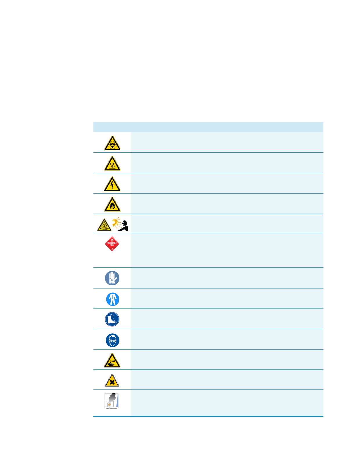
Symbol Descriptor
BIOHAZARD: Indicates that a biohazard will, could, or might occur.
BURN HAZARD: Alerts you to the presence of a hot surface that could or
might cause burn injuries.
ELECTRICAL SHOCK HAZARD: Indicates that an electrical shock could or
might occur.
FIRE HAZARD: Indicates a risk of fire or flammability could or might occur.
EXPLOSION HAZARD. Indicates an explosion hazard. This symbol indicates
this risk could or might cause physical injury.
FLAMMABLE GAS HAZARD. Alerts you to gases that are compressed,
liquefied or dissolved under pressure and can ignite on contact with an
ignition source. This symbol indicates this risk could or might cause physical
injury.
GLOVES REQUIRED: Indicates that you must wear gloves when performing a
task or physical injury could or might occur.
CLOTHING REQUIRED. Indicates that you should wear a work clothing when
performing a task or else physical injury could or might occur.
BOOTS REQUIRED. Indicates that you must wear boots when performing a
task or else physical injury could or might occur.
MATERIAL AND EYE HAZARD. Indicates you must wear eye protection
when performing a task.
HAND AND CHEMICAL HAZARD: Indicates that chemical damage or
physical injury could or might occur.
HARMFUL. Indicates that the presence of harmful material will, could, or
might occur.
INSTRUMENT DAMAGE: Indicates that damage to the instrument or
component might occur. This damage might not be covered under the
standard warranty.
xviii TriPlus 500 Headspace Sampler User Guide Thermo Scientific
Page 19
Preface
3
Instrument Markings and Symbols
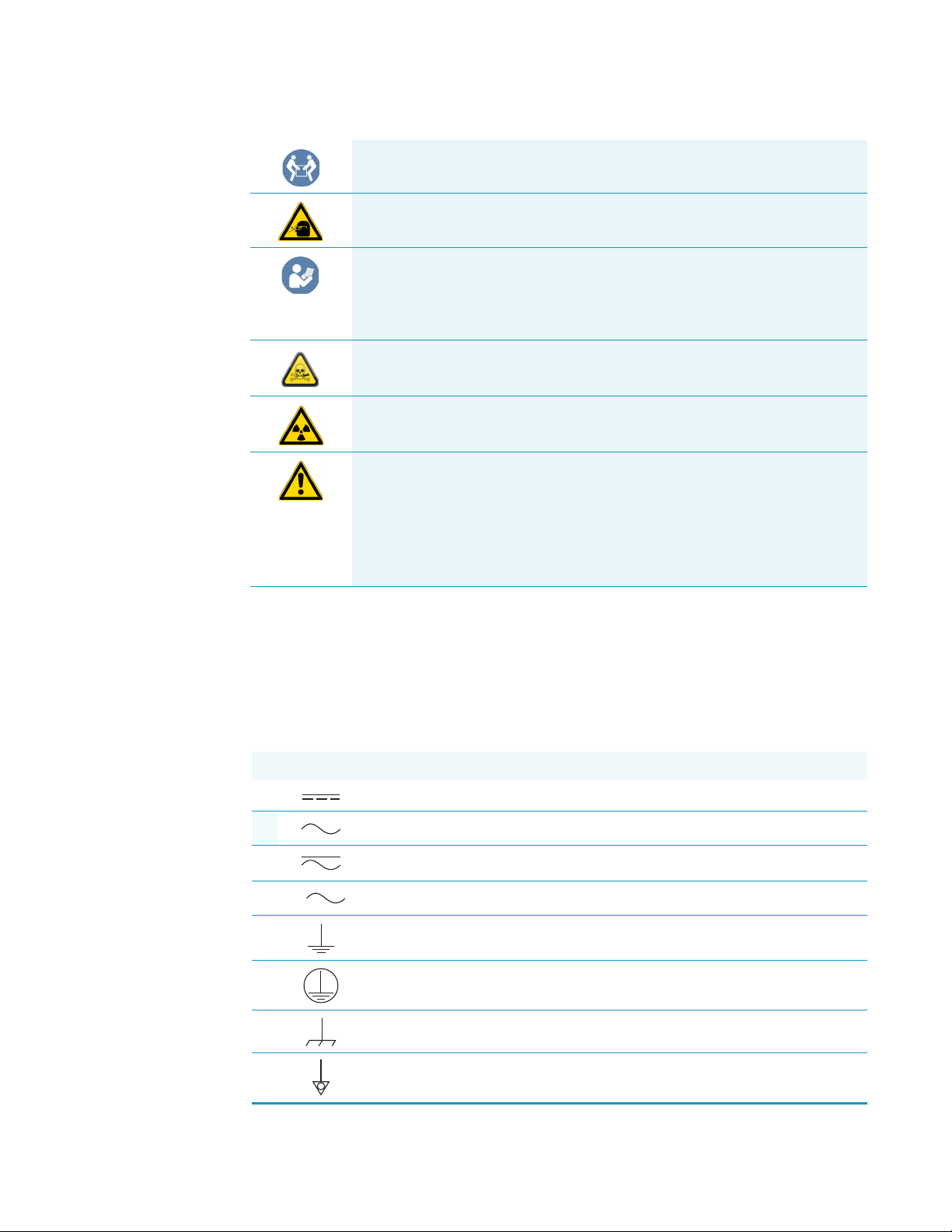
LIFTING HAZARD. Indicates that a physical injury could or might occur if
two or more people do not lift an object.
MATERIAL AND EYE HAZARD: Indicates that eye damage could or might
occur.
READ MANUAL: Alerts you to carefully read your instrument’s
documentation to ensure your safety and the instrument’s operational ability.
Failing to carefully read the documentation could or might put you at risk for
a physical injury.
TOXIC SUBSTANCES HAZARD: Indicates that exposure to a toxic substance
could occur and that exposure could or might cause personal injury or death.
RADIOACTIVE HAZARD. Indicates that the presence of radioactive material
could or might occur.
For the prevention of personal injury, this general warning symbol precedes
the WARNING safety alert word and meets the ISO 3864-2 standard. In the
vocabulary of ANSI Z535 signs, this symbol indicates a possible personal
injury hazard exists if the instrument is improperly used or if unsafe actions
occur. This symbol and another appropriate safety symbol alerts you to an
imminent or potential hazard that could cause personal injury.
Instrument Markings and Symbols
Ta bl e 1 explains the symbols used on Thermo Fisher Scientific instruments. Only a few of
them are used on TriPlus 500 HS, which are annotated with an asterisk below.
Table 1. Instrument Marking and Symbols (Sheet 1 of 2)
Symbol Description
Direct Current
* Alternating Current
Both direct and alternating current
Three-phase alternating current
Earth (ground) terminal
Protective conductor terminal
Frame or chassis terminal
Equipotentiality
Thermo Scientific TriPlus 500 Headspace Sampler User Guide xix
Page 20
Preface
Safety Information and Warnings
Table 1. Instrument Marking and Symbols (Sheet 2 of 2)
Symbol Description
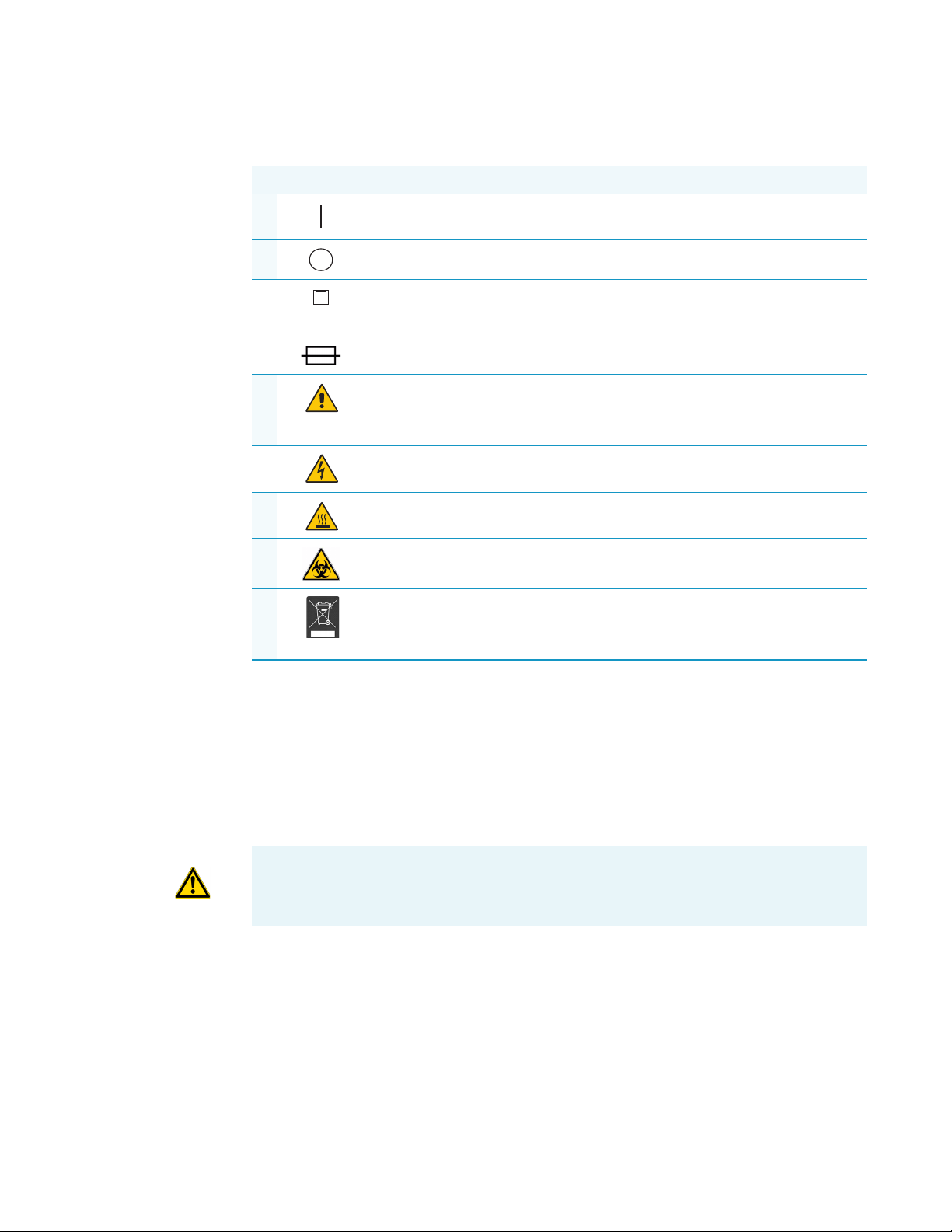
* On (Supply)
* Off (Supply)
Equipment protected throughout by DOUBLE INSULATION or
REINFORCED INSULATION (Equivalent to Class II of IEC 536)
Fuse
* Instruction manual symbol affixed to product. Indicates that the you must
refer to the manual for specific WARNING or CAUTION information to
avoid personal injury or damage to the product.
Caution, risk of electric shock
* Caution, hot surface
* Caution, biohazard
* Symbol in compliance to the Directive 2012/19/EU on Waste Electrical
and Electronic Equipment (WEEE) placed on the European market after
August, 13, 2005.
Safety Information and Warnings
This safety guide raises awareness of potential safety issues and general points for
consideration for Thermo Fisher Scientific representatives during installation, and repair of
TriPlus 500 HS, or parts of it (following the life cycle principle), as well as for the end user of
TriPlus 500 HS in the lab during the learning phase, and in routine work.
IMPORTANT Read this section first before operating with TriPlus 500 HS.
General Considerations
• Before a unit is put to use, consult the TriPlus 500 HS manuals and related documents
under all circumstances.
• Changes or modifications to this unit not expressly approved by the party responsible for
compliance, could void your authority to operate the equipment.
xx TriPlus 500 Headspace Sampler User Guide Thermo Scientific
Page 21
Electrical Hazards
Preface
Safety Information and Warnings
• Be aware that if the equipment is used in a manner not specified by the manufacturer, the
protective and safety features of the equipment might be impaired.
• The repair of instrument failures caused by operation in a manner not specified by the
manufacturer is expressly excluded from the standard warranty and service contract
coverage.
• When for technical reasons it is necessary to work on instrument parts which might
involve a potential hazard (heated/moving parts, components under voltage, and so on)
contact the Thermo Fisher Scientific authorized representative.
Routine maintenance operations can be performed by a Thermo Fisher Scientific
representative. Alternatively they can be performed by a trained operator. Routine
maintenance can be performed according to the instructions reported in the TriPlus 500
Headspace Sampler Hardware Manual.
Every analytical instrument has specific hazards. Be sure to read and comply with the
following precautions. They ensure the safety and long-term use of your TriPlus 500 HS.
The installation over-voltage category is Level II. The Level II category pertains to equipment
receiving its electrical power from the local level, such as an electrical wall outlet.
The power line and the connections between TriPlus 500 HS and other instruments, used in
the configuration setup of the total analytical system, must maintain good electrical
grounding. Poor grounding represents a danger for the operator, and might seriously affect the
performance of the instrument.
Do not connect TriPlus 500 HS to power lines that supply devices of a heavy duty nature,
such as motors, refrigerators and other devices that can generate electrical disturbances.
Use only fuses of the type and current rating specified. Do not use repaired fuses, and do not
short-circuit the fuse holder. The supplied power cord must be inserted into a power outlet
with a protective earth (ground) contact. When using an extension cord, make sure that the
cord also has an earth contact.
If the supplied power cord does not fit the local electrical socket and a replacement or adapter
has to be purchased locally, make sure that only a certified power cord is used. Any power cord
used must be certified by the appropriate local authorities.
Do not to leave any cable connecting TriPlus 500 HS and the chromatographic system, or the
power cord close to heated zone, such as the injector or detector heating blocks, or the GC hot
air vents.
Always replace any cable showing signs of damage with another one provided by the
manufacturer. Safety regulations must be respected.
Thermo Scientific TriPlus 500 Headspace Sampler User Guide xxi
Page 22
Preface
Safety Information and Warnings
Do not change the external or internal grounding connections. Tampering with or
disconnecting these connections could endanger you and damage the TriPlus 500 HS.
The instrument is properly grounded in accordance with these regulations when shipped.
To ensure safe operation, do not make any changes to the electrical connections or the
instrument's chassis.
Do not turn the instrument on if you suspect that it has incurred any type of electrical
damage. Instead, disconnect the power cord and contact a Thermo Fisher Scientific
representative for a product evaluation. Do not attempt to use the instrument until it has been
evaluated. Electrical damage might have occurred if TriPlus 500 HS shows visible signs of
damage, exposure to any liquids or has been transported under severe stress.
Damage can also result if the instrument is stored for prolonged periods under unfavorable
conditions: for example, subjected to heat, moisture, and so on. Ensure that the power
supply/controller unit is always placed in a clean and dry position. Avoid any liquid spills in
the vicinity.
Before attempting any type of maintenance work, always disconnect the power cords from the
power supply if optional devices are installed. Capacitors inside the instrument might still be
charged also if the instrument is turned off.
To avoid damaging electrical parts, do not disconnect an electrical assembly while power is
applied to TriPlus 500 HS. After the power is turned off, wait approximately 30 seconds
before you disconnect an assembly.
Other Hazards
The instrument includes a number of integrated circuits. These circuits might be damaged if
exposed to excessive line voltage fluctuations, power surges or electrostatic charges, or both.
The power supply for TriPlus 500 HS has the symbols I/O on the label for the power switch
to indicate On/Off. It is important that the power On/Off switch is accessible to unplug the
AC power cord from the power supply/wall outlet in case of emergency.
Danger of crushing to fingers and hands. To avoid injury keep your hands away from moving
parts during operation. Turn off the power to TriPlus 500 HS if you must reach inside a
mechanically powered system with moving parts.
To avoid injury, observe safe laboratory practice when handling solvents, changing tubing, or
operating the TriPlus 500 HS. Know the physical and chemical properties of the solvents you
use. See the Safety Data Sheets (SDS) from the manufacturer of the solvents being used.
When using TriPlus 500 HS, follow the generally accepted procedures for quality control and
method development.
Do not operate on the instrument components that form part of the work area of TriPlus 500
HS when it is in motion.
xxii TriPlus 500 Headspace Sampler User Guide Thermo Scientific
Page 23
Do not use vials without a sealing cap. Vapor phase from organic solvents can be hazardous
and flammable. Acidic vapor phase can cause corrosion to critical mechanical parts.
Use high quality vials and closures as depending on the application conditions, high pressure
can build up in the vial. Do not reuse headspace vials. Repeated heating of reused vials may
increase the chance of vial breaking.
Working with Toxic or other Harmful Compounds
WARNING Before using hazardous substances (toxic, harmful, and so on), please read the
hazard indications and information reported in the applicable Safety Data Sheet (SDS).
Use personal protective equipment according to the safety requirements.
• Protective gloves: Loose fitting thermal insulated or leather gloves.
• Eye protection: Full face shield and safety glasses are recommended.
• Other protective equipment: Safety shoes when handling containers. Long sleeved
shirts and trousers without cuffs. Work clothing that sufficiently prevents skin contact
should be worn.
Preface
Safety Information and Warnings
Biological Hazards
Before using dangerous substances (toxic, harmful, and so on), read the hazard indications
and information reported in the Safety Data Sheet (SDS) supplied by the manufacturer,
referring to the relevant CAS (Chemical Abstract Service) number.
TriPlus 500 HS may require the use of several chemical products with different hazard
characteristics, change which are present in vials. Before using these substances, please read the
hazard indications and information reported in the SDS supplied by the manufacturer
referring to the relevant CAS number.
When preparing the samples, please refer to local regulations for the ventilation conditions of
the work room.
All waste materials must be collected and eliminated in compliance with the local regulations
and directives in the country where the instrument is used.
ATTE NTIO N If using dangerous or flammable solvents, it is suggested to work with a fume
hood placed over the TriPlus 500 HS.
In laboratories where samples with potential biological hazards are handled, you must label
any equipment or parts thereof which might become contaminated with biohazardous
material.
When working with biohazardous materials, it is your responsibility to fulfill the following
mandatory requirements:
Thermo Scientific TriPlus 500 Headspace Sampler User Guide xxiii
Page 24

Preface
Safety Information and Warnings
Maintenance
• Instructions on how to safely handle biohazardous material must be provided.
• Operators must be trained and made aware of the potential dangers.
• Personal protective equipment must be provided.
• Instructions must be provided on what to do in case operators are exposed to aerosols or
vapors during normal operation (within the intended use of the equipment) or in case of
single fault situations such as a broken vial.
The protective measures must consider potential contact with the skin, mouth, nose
(respiratory organs), and eyes.
• Instructions for decontamination and safe disposal of the relevant parts must be provided.
It is your responsibility to handle hazardous chemicals or biological compounds (including,
but not limited to, bacterial or viral samples and the associated waste), safely and in
accordance with international and local regulations.
Any external cleaning or maintenance must be performed with TriPlus 500 HS turned off and
the power cord disconnected.
Avoid using solvents and spraying on electrical parts. For the removal of potentially dangerous
substances (toxic, harmful, and so on) read the hazard indications and information reported
in the Safety Data Sheet (SDS) supplied by the manufacturer referring to the relevant CAS
(Chemical Abstract Service) number. Use proper protective gloves.
When working with hazardous materials such as radioactive, biologically hazardous material,
and so on, it is important to train all operators how to respond in case of spills or
contamination.
Depending on the class of hazardous material, the appropriate measures have to be taken
immediately. Therefore, the chemicals or solvents needed for decontamination have to be on
hand.
Any parts of the equipment which can potentially be contaminated, such as the sample vial
tray, and so on, must be cleaned regularly. The waste solvent from cleaning and any hardware
which requires to be disposed of has to be properly eliminated with all the necessary
precautions, abiding by national and international regulations.
When preparing for decontamination, ensure that the solvent or chemical to be used will not
damage or react with the surface, dye (color) of the instrument, table or other nearby objects.
If in doubt, please contact your Thermo Fisher Scientific representative to verify the
compatibility of the type or composition of solvents with TriPlus 500 HS.
xxiv TriPlus 500 Headspace Sampler User Guide Thermo Scientific
Page 25

Disposal
Preface
Writing Convention Used in This Guide
Do not dispose of this equipment or parts thereof unsorted in municipal waste.
Follow local municipal waste regulations for proper disposal provisions to reduce
the environmental impact of waste electrical and electronic equipment (WEEE).
European Union customers: Call your local customer service representative
responsible for TriPlus 500 HS for complimentary equipment pick-up and
recycling.
WARNING The customer has to ensure that TriPlus 500 HS has not been contaminated
by any hazardous chemical or biological compounds including (but not limited to)
bacteria or viruses.
Any part which had direct contact with the analytical sample must be identified and must
undergo an appropriate decontamination procedure prior to shipping for disposal.
Potentially dangerous components are vials and trays. Any critical parts sent for disposal
must be handled according to national laws for hazardous compounds.
The customer and the service engineer are fully responsible for enforcing these
requirements. Thermo Fisher Scientific will hold the representative, customer responsible,
or both, if these regulations are not observed.
Writing Convention Used in This Guide
ATTENTION For writing convenience the TriPlus 500 Headspace Sampler is identified or
as TriPlus 500 HS or simply as HS sampler.
Thermo Scientific TriPlus 500 Headspace Sampler User Guide xxv
Page 26

Page 27

1
Getting Familiar with Your TriPlus 500 Headspace Sampler
This chapter provides information to familiarize users with the TriPlus 500 Headspace
Sampler (TriPlus 500 HS or HS sampler).
Contents
• Introduction
• Instrument Basics
• Label Location on the Instrument
• Incubation Group
• Sampling Path
• Pneumatic Connections
• Electrical Connections
• Status Panel
• TRACE 1310 GC User Interface
• Vial Loader
• Sample Trays
• Barcode Reader
• Heated/Cooled Tray
• TriPlus 500 Web Interface
Thermo Scientific TriPlus 500 Headspace Sampler User Guide 1
Page 28
1
Getting Familiar with Your TriPlus 500 Headspace Sampler
Introduction
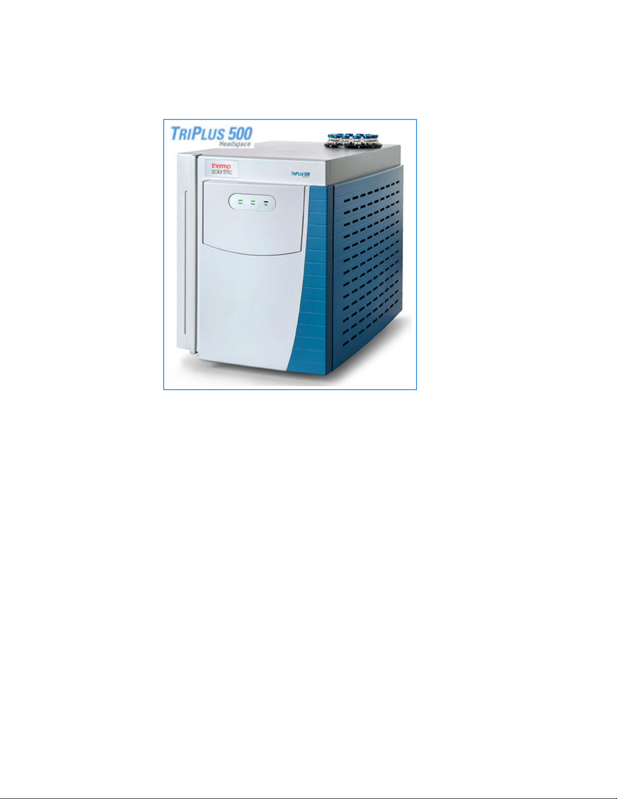
Introduction
The TriPlus 500 HS is an
automatic sampler for headspace
gas chromatographic (HSGC)
analysis for the determination of
volatile compounds in a liquid
or solid matrices.
The samples are placed in
headspace vials, tightly closed
with a suitable cap and septum.
Each vial is heated, and the
volatile compounds are
transferred from the solid or
liquid sample into the gaseous
phase above it, called headspace,
until a condition of
thermodynamic equilibrium is
reached.
Afterwards, an aliquot of
headspace is withdrawn and
injected into the gas chromatograph. Details on the principles of operation are available in the
section “Analytical Cycle” on page 34.
Besides a sampling technique, the headspace technique is also an extraction and concentration
technique. It offers the advantages of a reduced manipulation of the sample, a higher
sensitivity than the direct injection, and a longer lifetime of chromatographic columns since
only the volatile fraction is injected into the column.
The TriPlus 500 HS is directly coupled with a TRACE 1300 Series GC and controlled by a
Thermo Scientific Chromatography Data System, through the GC touch screen, if available,
or the virtual GC user interface.
2 TriPlus 500 Headspace Sampler User Guide Thermo Scientific
Page 29
Instrument Basics
TriPlus 500 HS-12
TRACE 1300 GC
TriPlus 500 HS-12
TRACE 1310 GC
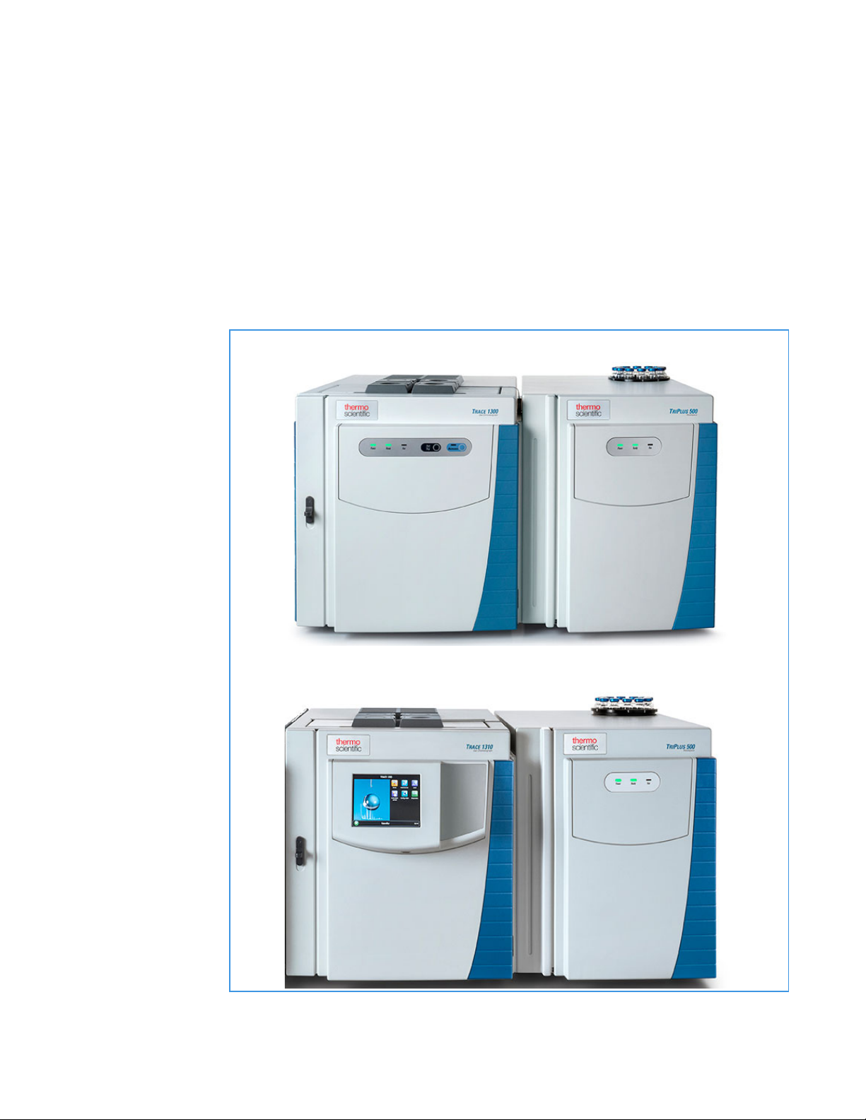
The TriPlus 500 Headspace Sampler (TriPlus 500 HS) consists of a 12-vial capacity
configuration (TriPlus 500 HS-12), upgradeable to 120-vial capacity with the addition of a
vial loader and a tray holder with three removable 40-vial trays (TriPlus 500 HS-120). The
TriPlus 500 HS-120 can be further extended to 240-vial capacity with an additional tray
holder and three 40-vial trays on the top of the GC.
See Figure 1 and Figure 2.
Figure 1. TriPlus 500 HS-12 Coupled with a TRACE 1300 Series GC
1
Getting Familiar with Your TriPlus 500 Headspace Sampler
Instrument Basics
Thermo Scientific TriPlus 500 Headspace Sampler User Guide 3
Page 30
1
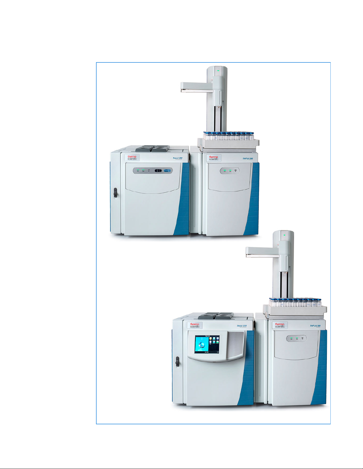
TriPlus 500 HS-120
Sample Vial Trays
TriPlus 500 HS-120
TRACE 1310 GC
TRACE 1300 GC
TriPlus 500 Vial Loader
Getting Familiar with Your TriPlus 500 Headspace Sampler
Instrument Basics
Figure 2. TriPlus 500 HS-120 Coupled with a TRACE 1300 Series GC
4 TriPlus 500 Headspace Sampler User Guide Thermo Scientific
Page 31

1
Getting Familiar with Your TriPlus 500 Headspace Sampler
Instrument Basics
TriPlus 500 HS-12 includes:
• Sample Carousel — A 12-seat rotating carousel for 10 mL and 20/22 mL vials.
• Incubation Oven — A heated box including a 12-seat rotating oven carousel and
mechanisms for shaking and transferring the vial. See “Incubation Group” on page 8.
• Sampling Path — Includes an electrically actuated 6-port gas sampling valve, a sampling
needle and the GC column interface. See “Sampling Path” on page 9.
• Pneumatic Connections — Connect the supplies of carrier gas and auxiliary gas.
See “Pneumatic Connections” on page 11.
• Electrical Connections— Includes electrical supply and communications ports to the GC
optional devices. See “Electrical Connections” on page 12.
• Status Panel — Consists of three light emitting diodes (LED) showing the current status
of the instrument. See “Status Panel” on page 13.
Note The TriPlus 500 HS-12 can be upgraded to a 120-sample-vial capacity at any time
by adding the Vial Loader and the tray holder with three 40-vial trays.
TriPlus 500 Vial Loader includes:
• One tray holder with three 40-vial trays. See “Sample Trays” on page 19.
• Vial Loader — A robotic arm with a magnetic gripper that transfers the vials from each of
the vial trays to the 12-position sample carousel, and vice-versa. The Vial Loader controls
optional devices such as the Barcode Reader and Heated/Cooled Tray (Chiller). See
“Vial Loader” on page 16, “Barcode Reader” on page 23, and“Heated/Cooled Tray” on
page 28.
Note The sampling capacity of the TriPlus 500 HS-12 can be increased to 240 vials
adding by another tray holder with three 40-vial trays placed on the back part of a
TRACE 1300 Series GC top cover.
Each sample tray has its own identification initials according to its position on the
TriPlus 500 HS, GC, or on both. This allows for proper management of the vials during
the sample sequence.
Thermo Scientific TriPlus 500 Headspace Sampler User Guide 5
Page 32

1
GC Sample Tray B
GC Sample Tray C
GC Sample Tray A
Optional
Barcode Reader
Vial Loader
Optional
Heated/Cooled
Tray IN/OUT
Connections
HS Sample Tray C
HS Sample Tray B
HS Sample Tray A
Getting Familiar with Your TriPlus 500 Headspace Sampler
Instrument Basics
ATTENTION DO NOT PLACE a vial into the 12-position rotating carousel when using
the Vial Loader and the Vial Trays. The Vial Loader carries one vial at a time into the
pre-defined position 1 of the carousel, while the other 11 positions are all potentially used
for vial recovering.
Figure 3 shows an example of sampling system.
Figure 3. Example of the Sampling System at the Maximum Configuration
6 TriPlus 500 Headspace Sampler User Guide Thermo Scientific
Page 33

Label Location on the Instrument
Instrument model,
Serial number, Part
number and Electrical
Data
MAC address (Media
Access Control)
Alert label
Alert label
MAC: XX:XX:XX:XX:XX:XX
Vials could
be hot
Alert label
Figure 4 shows the location of the labels attached to the TriPlus 500 HS.
Figure 4. Labels
1
Getting Familiar with Your TriPlus 500 Headspace Sampler
Label Location on the Instrument
Thermo Scientific TriPlus 500 Headspace Sampler User Guide 7
Page 34

1
Sample vial carousel
Incubation oven housing
Getting Familiar with Your TriPlus 500 Headspace Sampler
Incubation Group
Incubation Group
The Incubation Group includes the Sample Vial Carousel and the Incubation Oven. See
Figure 5.
Figure 5. Incubation Group
Sample Vial Carousel
The sample vial carousel consists of a 12-seat rotating carousel, numbered from 1 to 12, for
vial housing. The carousel includes a mechanism for the automatic introduction and
extraction of a vial into and from the incubation oven through the incubation door.
The incubation door has two positions: Open and Closed.
• Open — The door is open during the vial introduction and extraction into and from the
• Closed — The door always remains in this position except when a vial is introduced or
incubation oven.
extracted from the oven.
8 TriPlus 500 Headspace Sampler User Guide Thermo Scientific
Page 35

Incubation Oven
Sampling Path
1
Getting Familiar with Your TriPlus 500 Headspace Sampler
The incubation oven consists of a heated box including a 12-seat rotating oven carousel.
The vials are accurately thermostatted up to 300 °C and a fan provides a constant and
uniform temperature. The vials are automatically inserted into the oven carousel from the
sample vial carousel and can be shaken during the equilibration phase through the movements
of the carousel.
Two motor-driven levers lift the vials out of the incubation carousel for sampling when they
are placed in correspondence with the sampling needle, or for their recovery when they are
placed under the inlet/outlet hole of the incubation oven.
The sampling path consists of an electrically actuated 6-port sampling valve equipped with a
deactivated stainless-steel sample loop, a sampling needle, and the valve-column interface.
The valve assembly ends with a deactivated splitter, placed inside an insulating metal box, for
the connection to the analytical column into the oven of the GC. See Figure 6.
Sampling Path
Thermo Scientific TriPlus 500 Headspace Sampler User Guide 9
Page 36

1
Sampling system housing
Valve-column interface
Getting Familiar with Your TriPlus 500 Headspace Sampler
Sampling Path
Figure 6. Sampling Path
10 TriPlus 500 Headspace Sampler User Guide Thermo Scientific
The sampling valve group is protected by a thermally insulated metal box. The valve is heated
up to 225 °C with the standard factory-installed valve. An optional high temperature valve is
available to heat the valve in range from 150 °C up to 300 °C.
ATTENTION The valve must be used only in the specified temperature range. DO NOT
EXCEED THIS RANGE.
A wide range of sample loops allows injection of different volumes of samples.
The sample loop is installed between the ports 3 and 6 of the sampling valve. The standard
volume of the loop is 1.0 mL.
The following optional sample loops are available: 25 μL, 50 μL, 100 μL, 500 μL, and 3 mL.
Page 37

Pneumatic Connections
Vent outlet port
Aux gas inlet port
Adapter
To Back SSL Injector
To Carrier manifold
inlet ports
Carrier
manifold
The pneumatic interface includes the inlet and outlet ports to make the pneumatic
connections with the sampling path and the external devices. See Figure 7.
Figure 7. Pneumatic Interface
1
Getting Familiar with Your TriPlus 500 Headspace Sampler
Pneumatic Connections
The pneumatic interface includes:
• A manifold for connecting the carrier gas coming from the Back SSL injector module on
the GC through a dedicated adapter.
Note For installing and connecting the adapter between the Back SSL injector
module on the GC and the TriPlus 500 HS, refer to the TriPlus 500 Headspace
Sampler Hardware Manual.
•An inlet port marked Aux gas input (550 kPa - 80 PSI Max) for connecting the auxiliary
gas supply from the cylinder.
•An outlet port marked Ve nt for connecting the HS sampler to an exhaust device.
.
Note Carrier gas input connection is not currently in use.
Thermo Scientific TriPlus 500 Headspace Sampler User Guide 11
Page 38

1
AC input
connector
Power
switch
Carousel heating fans
Electronic module
Cooling
fan
Power
section
Getting Familiar with Your TriPlus 500 Headspace Sampler
Electrical Connections
Electrical Connections
The electrical interface includes the power section and the electronic module to make
electrical and communication connections among the HS sampler and the external devices.
See Figure 8.
Figure 8. Electrical Interface
12 TriPlus 500 Headspace Sampler User Guide Thermo Scientific
The power section includes:
• The Power Switch marked Power to turn the instrument On/Off.
– Position ON = instrument powered On
– Position OFF = instrument powered Off
• AC Input connector (Main socket) for connecting the power cable to the sampler and the
wall outlet
The power rating is: 100-240 Vac, 50/60 Hz; 600 W
Page 39

Status Panel
1
Getting Familiar with Your TriPlus 500 Headspace Sampler
The electronic module includes:
•Two ports marked TFS BUS (IN) and TFS BUS (OUT) for the interconnection with the
TriPlus 500 HS units such as the Vial Loader.
• A RJ45 connector marked LAN for connecting to the network.
• A button marked IP Reset for resetting the IP address.
• A 9-pin connector marked GC to synchronize the HS sampler with the GC (Ready
In/Out and Start In/Out signals). See the Autosampler connector on the back of the
TRACE 1300 Series GC.
The Status Panel consists of three light emitting diodes (LED), on the front door of TriPlus
500 HS, showing the instrument’s current status. See Figure 9.
Figure 9. Status Panel
Status Panel
The three LEDs are:
• Power — When the LED lights are green, the HS sampler is powered on.
• Ready — When the LED lights are green, the HS sampler is in Ready condition. When
the LED blinks orange the HS sampler is in Not Ready condition.
• Run — When the LED lights are blue, the HS sampler is running an analysis.
Every instrument’s event/phase is associated with a status of the LED as detailed below:
1. Power On TriPlus 500 HS
All the LEDs on the status panel light up simultaneously. Next, the Power light becomes
a solid green, while the Run light flashes during the initialization phase. See Figure 10.
Thermo Scientific TriPlus 500 Headspace Sampler User Guide 13
Page 40

1
Getting Familiar with Your TriPlus 500 Headspace Sampler
Status Panel
Figure 10. Power On
2. Not Ready status
When the HS sampler is in Not Ready status, the Ready light blinks orange.
See Figure 11.
Figure 11. Not Ready Status
3. Ready status
When the sampler parameters have reached the setpoint values, the Ready light becomes a
solid green. See Figure 12.
Figure 12. Ready Status
4. Run status
When the sampler is running, the Run lights solid blue, while the Ready lights off.
See Figure 13.
Figure 13. Run Status
5. Error
When an alarm condition is detected, the Power light is blinking. See Figure 14.
Figure 14. Error Condition
14 TriPlus 500 Headspace Sampler User Guide Thermo Scientific
Page 41

TRACE 1310 GC User Interface
Headspace Sampler Main Menu
The Human-Machine Interface (HMI) of the TRACE 1310 GC recognizes the connected
TriPlus 500 HS. The relevant icon is visualized on the touch screen to open the Headspace
Sampler Main Menu. See Figure 15.
Figure 15. Touch Screen Main Menu - Headspace Sampler Icon
1
Getting Familiar with Your TriPlus 500 Headspace Sampler
TRACE 1310 GC User Interface
CAUTION For setting the HS sampler parameters see the Chapter 3, “Setting Up Through
the TRACE 1310 User Interface.”
Thermo Scientific TriPlus 500 Headspace Sampler User Guide 15
Page 42

1
Gripper assembly
Vial capture device
Power LED
Loader arms assembly
Turr et
Getting Familiar with Your TriPlus 500 Headspace Sampler
Vial Loader
Vial Loader
The Vial Loader is a device for upgrading the sampling capacity up to 120 vials adding up to
three 40-position sample trays. The sampling capacity can be further increased up to 240 vials
adding other three 40-position sample trays placed on the back part of a TRACE 1300 Series
GC top cover.
The device transfers one vial at a time from the sample tray to the pre-defined position 1 of
the 12-position sample carousel, and vice-versa. The Vial Loader can control additional
external devices such as the Barcode Reader and a Chiller connected to the Heated/Cooled
Tr a y .
The Vial Loader consists of the following parts. See Figure 16.
Figure 16. Vial Loader
16 TriPlus 500 Headspace Sampler User Guide Thermo Scientific
Tu r r e t — Includes the mechanisms for moving the loader arms assembly.
Power LED — When the Power LED light is solid green, the Vial Loader is powered on.
The power LED light blinks green during the movements of the loader arms.
Loader arms assembly — Transfers the sample vial from a sample tray to the sample carousel
and vice-versa through the Vial capture device located on the bottom of the Gripper
assembly.
Gripper assembly — Captures the vial and carries it from a sample tray holder to the sample
carousel and vice-versa through the four magnets of the capture device.
Page 43

Vial Loader Electronic Module
MAC code
Instrument model, Serial
number, Part number and
Electrical Data
China RoHS Label
1
Getting Familiar with Your TriPlus 500 Headspace Sampler
Vial Loader
The electronic module on the back of the Vial Loader includes the connectors to make
electrical and communication connections. See Figure 17.
Figure 17. Vial Loader Electronic Module
Thermo Scientific TriPlus 500 Headspace Sampler User Guide 17
Page 44

1
Getting Familiar with Your TriPlus 500 Headspace Sampler
Vial Loader
The electronic module includes:
• The Power Switch to turn the instrument On/Off.
– Position I = instrument On
– Position O = instrument Off
• A jack socket marked for the instrument power supply through a portable
external power supply, level VI efficiency.
24 Vdc through a portable external power supply, level VI efficiency
Input 100-240 Vac; 50/60 Hz; 1.3 A— Output 24 Vdc; Power 90 W; 3.75 A
WARNING You must only use the portable external power supply furnished with the
instrument by Thermo Fisher Scientific.
• Two ports marked TFS BUS (IN) and TFS BUS (OUT) are for the interconnection with
the units of the TriPlus 500 HS as the Vial Loader.
• A 9-pin connector marked GC to synchronize the HS sampler with the GC (Ready
In/Out and Start In/Out signals). See the connector marked Autosampler on the back of
the TRACE 1300 Series GC.
• Two USB ports marked EXT 1 and 2 for the connection to external devices,
controlled by the Vial Loader, as Barcode Reader and Chiller.
• A 8-pin connector marked EXT 3 for the connection to an auxiliary external device.
• A button marked IP Reset to reset the IP address.
18 TriPlus 500 Headspace Sampler User Guide Thermo Scientific
Page 45

Sample Trays
First row = Vial 1 to Vial 10
Second row = Vial 11 to Vial 20
Third row = Vial 21 to Vial 30
Fourth row = Vial 31 to Vial 40
1
11
21
31
10
20
30
40
1
Getting Familiar with Your TriPlus 500 Headspace Sampler
Sample Trays
The sample tray can contain up to forty 10 mL or 20/22 mL vials arranged on four rows.
See Figure 18 and Figure 19.
Figure 18. 40-position Sample Tray (1)
Figure 19. 40-position Sample Tray (2)
Figure 20 shows the typical sampling sequence from vial 1 to vial 40.
Figure 20. Typical Vial Sampling Sequence
Each sample tray has its own identification initials according to the positioning on the TriPlus
500 HS, TRACE 1300 Series GC, or on both the instruments:
• HS Sample Tray A, B, and C — Sample trays installed on the top cover of a TriPlus 500
HS
• GC Sample Tray A, B, and C — Sample trays installed on the top cover of a TRACE
1300 Series GC
See Figure 21 and the TriPlus 500 Headspace Sampler Hardware Manual for more
information.
Thermo Scientific TriPlus 500 Headspace Sampler User Guide 19
Page 46

1
GC Sample Tray B
GC Sample Tray C
HS Sample
Tray A
HS Sample
Tray B
HS Sample
Tray C
GC Sample Tray A
Getting Familiar with Your TriPlus 500 Headspace Sampler
Sample Trays
Figure 21. Sample Trays Positioning
IMPORTANT Because the sample trays have all the same vial numbering from 1 to 40,
when programming a sequence of samples it is mandatory to specify the trays used and the
number of vials placed in each sample tray.
DO NOT place 10 mL and 20/22 mL vials into the same sample tray.
If 10 mL and 20/22 mL vials are used simultaneously, the 20/22 mL vials can only be
placed on HS Sample Tray C and/or GC Sample Tray A.
For further details see the sections “Vials Sequence Syntax” on page 21 and “Positioning
the Vials in the Sample Tray” on page 22.
Note An optional metallic version of the sample tray is available for heating/cooling the
vial. See “Heated/Cooled Tray” on page 28.
20 TriPlus 500 Headspace Sampler User Guide Thermo Scientific
Page 47

Vials Sequence Syntax
This section provides the correct syntax for identifying the position of the vials when
compiling the sample table (column Position) for the sequence of the samples.
Syntax for Sample Carousel
Sample Carousel:
• Syntax for the vials in the carousel = 1................12
Syntax for Sample Trays
Sample trays installed on TriPlus 500 HS Sampler:
• Syntax for the vials in the HS Sample Tray A = HS:A1................HS:A40
• Syntax for the vials in the HS Sample Tray B = HS:B1................HS:B40
• Syntax for the vials in the HS Sample Tray C = HS:C1................HS:C40
1
Getting Familiar with Your TriPlus 500 Headspace Sampler
Sample Trays
Sample trays installed on a TRACE 1300 Series GC:
• Syntax for the vials in the GC Sample Tray A = GC:A1................GC:A40
• Syntax for the vials in the GC Sample Tray B = GC:B1................GC:B40
• Syntax for the vials in the GC Sample Tray C= GC:C1................GC:C40
Example of vials setting in the sample table:
Only using Carousel without Vial Loader Using Vial Loader and Sample Trays
Position Position
1HS:A1
3HS:A2
3 HS:A23
4HS:B2
5HS:B40
6HS:C13
7GC:A7
.... ....
Thermo Scientific TriPlus 500 Headspace Sampler User Guide 21
Page 48

1
SAMPLE TRAY
SAMPLE TRAY
A
B
C
A
B
C
A
B
C
A
B
C
A
B
C
A
B
C
A
B
C
A
B
C
20 mL Vials
20 mL Vials
20 mL Vials
20 mL Vials
20 mL Vials
20 mL Vials
20 mL Vials
10 mL Vials
10 mL Vials
10 mL Vials
10 mL Vials
10 mL Vials
10 mL Vials
10 mL Vials
10 mL Vials
20 mL Vials
10 mL Vials
10 mL Vials
GC TRAY HOLDER
HS TRAY HOLDER
Getting Familiar with Your TriPlus 500 Headspace Sampler
Sample Trays
Positioning the Vials in the Sample Tray
ATTE NTIO N The sample tray can contain up to forty 10 mL or 20/22 mL vials arranged
on four rows. Each sample tray MUST contain vials of the same type. DO NOT place
10 mL and 20/22 mL vials into the same sample tray.
In the case both 10 mL and 20/22 mL vials are used, they must be placed in the system
according to the scheme of Figure 22.
Figure 22 shows the possible positioning of the 10 mL and 20/22 mL vials into the HS and
GC Sample Trays A, B and C.
Figure 22. Sample Vials Positioning
22 TriPlus 500 Headspace Sampler User Guide Thermo Scientific
Page 49

Barcode Reader
Optical scanner
USB connector
Instrument model, Serial
number, Part number and
Electrical Data
1-D barcode
2-D barcode
This device allows the instrument to read barcodes on labels. Stickers with the barcode
containing the codified data of the samples are glued on the wall of the relevant sample vials.
See Figure 23.
Figure 23. Barcode Reader
1
Getting Familiar with Your TriPlus 500 Headspace Sampler
Barcode Reader
About a Barcode Reader
Thermo Scientific TriPlus 500 Headspace Sampler User Guide 23
A barcode is an optical machine-readable representation of data relative to the object to which
is attached.
Originally, the barcode represented data change by varying the widths and spacings of parallel
lines (linear or one-dimensional), later they evolved into rectangles, dots, hexagons, and other
two-dimensional (2-D) geometric patterns.
Page 50

1
Optical scanner
Rotating plate for
10 mL and 20/22 mL
vials
Motor
Rotation
mechanism
Bottom view
Top view
Read LED
Getting Familiar with Your TriPlus 500 Headspace Sampler
Barcode Reader
Barcode Reader Description
The Barcode Reader consists of the following main parts. See Figure 24.
Figure 24. Barcode Reader
• An optical scanner arm for enabling reading the barcode.
• A rotating plate for placing a 10 ml or 20/22 mL vial.
• A motor and a mechanism for rotating the vial for the complete reading of the barcode.
• A frontal Read LED which flashes every time a barcode label is read.
Barcode Label Positioning
The Barcode labels should be made of polyester and not paper. Polyester can withstand high
temperatures and the barcode lines will be printed clearly.
• Label Width — The minimum length of the barcode is 18 mm if used with a 20 mL vial.
This dimension refers to the actual barcode length and not the label itself. Adapt the label
accordingly. When possible use larger dimensions for reliable processing of the barcode.
• Maximum tilt of the barcode label: ±20°
• Minimal barcode density (minimal width of a bare or a space): 5 mil (0.005 in.) /
0.127 mm
Place the barcode label on the vial such that the barcode bars are horizontally positioned.
The allowed area for the placing of the label is given in Figure 25.
24 TriPlus 500 Headspace Sampler User Guide Thermo Scientific
Page 51

1
48.5 mm
7 mm
34 mm
Barcode application window 1D o QR-code.
Dimension QR-code: 7x7mm
78.5 mm
7 mm
58 mm
Vial 10 mL
Vial 20 mL
Ø22.5 mm
Ø22.5 mm
Getting Familiar with Your TriPlus 500 Headspace Sampler
Figure 25. Examples of Barcode Label Positioning and Label Size
Barcode Reader
• The operator can test reading the barcode label on the vial through the TriPlus 500 Web
Interface.
Thermo Scientific TriPlus 500 Headspace Sampler User Guide 25
• For details see Chapter 7, “Using the TriPlus 500 Web Interface.”
Page 52

1
Getting Familiar with Your TriPlus 500 Headspace Sampler
Barcode Reader
Supported Types of Barcode Symbols
Ta bl e 1 lists a series of barcode types that can be decoded.
Table 1. Barcode Symbology (Sheet 1 of 2)
Barcode Type Description
Key for Barcode Symbology
UPC-A Universal Product Code,
12 numerical digits.
11 usable digits +1 check digit.
UPC-E Universal Product Code,
Zero-compressed UPC code,
7 numerical digits.
6 usable digits + 1 check digit.
EAN-8 Derived from the longer European
Article Number (EAN-13),
8 numerical digits.
7 usable digits + 1 check digit.
Minimum
Length
12 12
66
77
Maximum
Length
Barcode Symbology
EAN-13 European (International) Article
Number, 13 numerical digits.
12 usable digits + 1 check digit.
Code-128 High density barcode for
alphanumerical codes, supporting all
128 ASCII characters.
EAN-128/GS10128 Alpha-numerical codes, supporting all
128 ASCII characters.
Code 39 (3 of 9) Alphanumeric code, consisting of
uppercase letters (A-Z), numeric digits
(0-9) and some special characters (-, .,
$, /, +,%, and space).
12 12
1 Unlimited
1 48
1 Unlimited
26 TriPlus 500 Headspace Sampler User Guide Thermo Scientific
Page 53

Table 1. Barcode Symbology (Sheet 2 of 2)
1
Getting Familiar with Your TriPlus 500 Headspace Sampler
Barcode Reader
Barcode Type Description
Minimum
Length
Maximum
Length
Barcode Symbology
2 of 5 Interleaved Numerical characters. 1 Unlimited
ISBT 128 Used for labeling of human blood. 1 Unlimited Application specific barcodes
QR-Code Two-dimensional 2D Barcode
77
symbology
Thermo Scientific TriPlus 500 Headspace Sampler User Guide 27
Page 54

1
Aluminum vial trays
IN/OUT fluid connector (2x)
Heated/cooled tray holder plate
Condensation collecting plate
IN/OUT fluid plug
(2x). Part of the
optional kit
IN/OUT pipe
adapter (2x).
Only the 8 mm
adapter comes
in the optional
kit.
Top view
Ducts for condensation drainage
Bottom view
Centering hole and slot
Getting Familiar with Your TriPlus 500 Headspace Sampler
Heated/Cooled Tray
Heated/Cooled Tray
The Heated/Cooled Tray is an optional accessory for heating/cooling all the vials on the
sample tray through the circulation of a fluid underneath the dedicated heated/cooled tray
holder plate. See Figure 26.
Figure 26. Heated/Cooled Tray Holder Plate
28 TriPlus 500 Headspace Sampler User Guide Thermo Scientific
Figure 27 shows a view of the aluminum heated/cooled vial tray.
Figure 27. Aluminum Heated/Cooled 40-position Vial Tray
Page 55

1
Working temperature range:
-10 °C to +80 °C (+14 °F to 176 °F)
Cooling capacity at 20 °C:
500 W / 1706 BTU
Heating capacity at 20 °C:
2 kW / 6829 BTU
Power supply:
230 V; 50 Hz
Dimensions (H x W x D):
62.0 x 23.2 x 48.7 cm
24.8 x 9.1 x 19.2 in.
Weight:
30 kg; 66 lb
Getting Familiar with Your TriPlus 500 Headspace Sampler
TriPlus 500 Web Interface
For heating and cooling the sample vials an external recirculating device is required. All the
control parameters must be set on the device in use by referring to the relevant manual.
Note If you do not have an external recirculating device in your laboratory, Thermo
Fisher Scientific recommends the Thermo Scientific™ Accel™ 500 LC Cooling/Heater
Recirculating Chiller Part Number 223422100. This model is directly controlled by the
data system. See Figure 28.
Figure 28. Accel 500 LC Optional Chiller
This heating/cooling method can be controlled through the Vial Loader and the Thermo
Scientific™ Chromeleon™ or TraceFinder™ Chromatography Data System.
For details, refer to the Thermo Scientific™ Accel™ Series Cooling/Heating Recirculating Chillers
Manual (P/N U01076).
Note Installation instructions for the Heated/Cooled Tray are in the TriPlus 500
Headspace Sampler Hardware Manual:
TriPlus 500 Web Interface
The TriPlus 500 Web Interface is a web-based application used for instrument control of the
TriPlus 500 HS. The operator can check the network configuration and the status of the
instrument. Also, it is possible to perform calibration of the tray holder, leak check and a
reading test of the barcode label on the vial.
For further details about the use of the TriPlus 500 Web Interface see Chapter 7, “Using the
TriPlus 500 Web Interface.”
Thermo Scientific TriPlus 500 Headspace Sampler User Guide 29
Page 56

Page 57

2
Operating Principles
This chapter describes the operating principles of the TriPlus 500 HS.
Contents
• Introduction to the Headspace Technique
• Pneumatics
• Analytical Cycle
Thermo Scientific TriPlus 500 Headspace Sampler User Guide 31
Page 58

2
Operating Principles
Introduction to the Headspace Technique
Introduction to the Headspace Technique
Headspace Gas Chromatography (HSGC) is an indirect method of analysis for the
determination of volatile components in liquid and solid samples. The principle of operation
of this technique is based on the gas chromatographic analysis of the sample gas vapor phase
in thermodynamic equilibrium with the sample in a closed vial. Under these conditions, the
quantity of volatile components in the headspace gas is proportional to their concentration in
the sample.
The gas chromatographic analysis of the gaseous phase proved to be the most practical and
reliable analytical method in the headspace technique. In fact, the combined use of this
technique and gas chromatography permits full exploitation of this analytical method (high
efficiency, sensitivity and selectivity) while preserving its basic simplicity, such as sample
preparation and reliability of results.
HSGC eliminates all the disadvantages connected with traditional sample preparation
requiring tedious and time-consuming procedures to concentrate the trace components, and
it avoids possible interference from non-volatile constituents.
This technique is also particularly suitable for the determination of traces in samples, which
cannot be injected directly into the gas chromatograph because of column overloading or
contamination, decomposition or dissociation problems. The main advantages of HSGC can
be summarized as follows:
• Only clean gas samples are injected, thus extending the column life time, promoting
higher sensitivity and easier use of selective detectors
• Preliminary sample preparation is negligible thus reducing the analysis time, which is of
primary importance in routine analysis
• Higher analytical sensitivity in the case of compounds whose partition coefficient is more
favorable towards the gas phase. In this case the absolute component amount injected
into the GC is larger than the maximum allowable liquid sample that might be injected
into the chromatographic system
• The sample is not vaporized in the GC, therefore its partial decomposition is avoided and
interference of other components eliminated
• Taking advantage of its intrinsically high modularity, TriPlus 500 HS expands the
capabilities of the TRACE 1300 Series GC
32 TriPlus 500 Headspace Sampler User Guide Thermo Scientific
Page 59

Pneumatics
2
Operating Principles
The pneumatic diagram of TriPlus 500 HS is schematically shown in Figure 29.
Figure 29. Pneumatic Diagram
Pneumatics
•The carrier gas is regulated by the GC. The carrier gas flows into the HS sampler through
the adapter gas tubing block installed on the Back SSL injector. The carrier gas used with
the GC can be helium, nitrogen, hydrogen, air or argon. Other gases are rarely used.
•The auxiliary gas pressurizes the vials and transfers the analytes from the sample into the
sample loop. The auxiliary gases used with the HS sampler are helium, nitrogen or argon.
The auxiliary gas is regulated by an electronic pressure control.
Thermo Scientific TriPlus 500 Headspace Sampler User Guide 33
Page 60

2
4
6
5
6
5
4
3
2
Column
1
Splitter
1 mL
Sample
Loop
Carrier Flow from SSL
Split Flow to SSL
To Detector
6-port Sampling Valve
Needle
VALVE OVEN
NEEDLE HEATER
INCUBATION OVEN
Charcoal Trap
On/Off
Val ve
Flow
Restrictor
Pressure Sensor 1
Pressure Sensor 2
EV1
Vent
AUX Gas
MANIFOLD
LOADING
Valve closed
Valve open
Operating Principles
Analytical Cycle
Analytical Cycle
The analytical cycle of a sample is made up of a sequence of operative phases starting from the
vial loading into the thermostatic oven until its unloading.
The operative phases are:
• “Stand-by” on page 34
• “Incubation” on page 36
• “Pressurization” on page 37
• “Leak Check” on page 38
• “Loop Filling” on page 39
• “Injection” on page 40
• “Purging” on page 42
Stand-by
The instrument is in stand-by condition before and after a sampling sequence, and between a
sampling and the next one of the same sequence. See Figure 30.
Figure 30. Stand-by Phase
34 TriPlus 500 Headspace Sampler User Guide Thermo Scientific
Page 61

2
Operating Principles
Analytical Cycle
The sampling valve is in Load position.
The proportional valve EV1 is closed while the On/Off valve is open. The carrier gas flows to
the GC through the sampling valve to feed the column.
If during the stand-by phase the parameter Stand-by Purge is active, EV1 and On/Off valve
are open. The auxiliary gas flushes at a constant flow rate through the sampling valve, the
sample loop, and the sampling needle to clean the circuit. See Figure 31.
Figure 31. Stand-by with Purge Phase
Pressure Sensor 2
Charcoal Trap
NEEDLE HEATER
Needle
INCUBATION OVEN
Pressure Sensor 1
EV1
Flow
Restrictor
On/Off
Valve
3
4
6
LOADING
5
5
6-port Sampling Valve
2
1
6
4
MANIFOLD
VALVE OVEN
1 mL
Sample
Loop
Valve open
Valve closed
AUX Gas
Vent
Carrier Flow from SSL
Split Flow to SSL
Splitter
Column
To Detector
Note The flow rate used during Stand-by, if active, is the same as set for the Purge level
in the method. See Ta bl e 2 .
Thermo Scientific TriPlus 500 Headspace Sampler User Guide 35
Page 62

2
Operating Principles
Analytical Cycle
Incubation
The incubation phase retains the same sampling valve configuration as the Stand-by phase
without purge or Stand-by with purge phase. See Figure 32.
Figure 32. Incubation Phase
Pressure Sensor 2
Charcoal Trap
NEEDLE HEATER
Needle
Sample
Vial
INCUBATION OVEN
Pressure Sensor 1
EV1
Flow
Restrictor
On/Off
Valve
3
4
6
LOADING
5
5
6-port Sampling Valve
2
1
6
4
MANIFOLD
VALVE OVEN
1 mL
Sample
Loop
Valve open
Valve closed
AUX Gas
Vent
Carrier Flow from SSL
Split Flow to SSL
Splitter
Column
To Detector
During the incubation phase the vial remains in the incubation oven at a constant
temperature.
Note During the incubation phase it is possible to stir the sample in the vials choosing the
appropriate vial shaking mode Slow, Medium, or Fast.
36 TriPlus 500 Headspace Sampler User Guide Thermo Scientific
Page 63

Pressurization
4
6
5
6
5
4
3
2
Column
1
Splitter
1 mL
Sample
Loop
6-port Sampling Valve
Needle
VALVE OVEN
NEEDLE HEATER
INCUBATION OVEN
Sample
Vial
Charcoal Trap
On/Off
Valve
Flow
Restrictor
Pressure Sensor 1
Pressure Sensor 2
EV1
MANIFOLD
LOADING
Vent
AUX Gas
Carrier Flow from SSL
Split Flow to SSL
Valve closed
Valve open
2
Operating Principles
Analytical Cycle
The pressurization phase starts at the end of the incubation time. If activated, the oven
carousel stops the shaking.
The Vial sampling lifter goes up to a different position according to the type of vial used (10
mL or 20/22 mL). The sampling valve is in Load position, EV1 and On/Off valve are open.
See Figure 33.
Figure 33. Pressurization Phase
Thermo Scientific TriPlus 500 Headspace Sampler User Guide 37
Three types of pressurization can be chosen:
• Pressurization at constant pressure — The pressure P2 is controlled by EV1 in order to
keep a default pressure rate increase until P2 reaches the Pressurization Pressure set.
• Pressurization at defined pressure rate increase — The pressure P2 is controlled by EV1
in order to keep a pressure rate increase set by the user until P2 reaches the pressurization
pressure set.
• Pressurization at defined pressurization time — The pressure P2 is controlled by EV1 in
order to keep a pressure rate increase defined by (Pressure set-Pressure initial)/Time,
where the time is set by the operator, until P2 reaches the pressurization pressure set.
Wait t he Pressure Equilibration Time set by the operator.
Page 64

2
Operating Principles
Analytical Cycle
Leak Check
After the system executes the vial pressurization, EV1 and On/Off valve are closed.
The system monitors the P2 decay, calculates the decay rate and compares with a set value to
assess if there is a leak in the vial. See Figure 34.
Figure 34. Leak Check Phase
Pressure Sensor 2
Charcoal Trap
NEEDLE HEATER
Needle
Sample
Vial
INCUBATION OVEN
Pressure Sensor 1
EV1
Flow
Restrictor
On/Off
Val ve
3
4
6
LOADING
5
5
6-port Sampling Valve
2
1
6
4
MANIFOLD
VALVE OVEN
1 mL
Sample
Loop
Valve open
Valve closed
AUX Gas
Vent
Carrier Flow from SSL
Split Flow to SSL
Splitter
Column
To Detector
38 TriPlus 500 Headspace Sampler User Guide Thermo Scientific
Page 65

Loop Filling
2
Operating Principles
Analytical Cycle
The sampling valve is in load position. EV and On/Off valve are open allowing the
pressurized sample to vent through the sample loop.
The filling stops when P2 reaches the set loop final pressure. Wait Loop Equilibration Time
set by the operator. See Figure 35.
Figure 35. Loop Filling Phase
Pressure Sensor 2
Charcoal Trap
NEEDLE HEATER
Needle
Sample
Vial
INCUBATION OVEN
EV1
Flow
Restrictor
3
4
6
LOADING
5
5
6
4
6-port Sampling Valve
Pressure Sensor 1
On/Off
Valve
MANIFOLD
VALVE OVEN
2
1
1 mL
Sample
Loop
AUX Gas
Vent
Splitter
Valve open
Valve closed
Carrier Flow from SSL
Split Flow to SSL
Column
To Detector
Thermo Scientific TriPlus 500 Headspace Sampler User Guide 39
Page 66

2
Operating Principles
Analytical Cycle
Injection
The sampling valve is in Inject position (Sampling). EV1 and On/Off valve are open.
The carrier gas flushes through the sampling valve and the sample loop moving the sample
towards the analytical column.
The auxiliary gas flows through the rest of the circuit and goes to the vent. See Figure 36.
Figure 36. Injection Phase
Pressure Sensor 2
Charcoal Trap
NEEDLE HEATER
Needle
Sample
Vial
INCUBATION OVEN
Pressure Sensor 1
EV1
Flow
Restrictor
On/Off
Valve
3
4
6
SAMPLING
5
5
6-port Sampling Valve
2
1
6
4
MANIFOLD
VALVE OVEN
1 mL
Sample
Loop
Valve open
Valve closed
AUX Gas
Vent
Carrier Flow from SSL
Split Flow to SSL
Splitter
Column
To Detector
The following injection phases can be chosen:
• Single injection
– The sample valve is set to inject position.
– Send Start signal to the GC.
– Venting phase (only if vial venting option is selected).
– The On/Off valve is open to vent the residual pressure of the vial.
– The sampling valve is set to load position when injection time is expired.
– The needle is removed from the vial.
40 TriPlus 500 Headspace Sampler User Guide Thermo Scientific
Page 67

•Enrichment
– The sampling valve is set to Inject position.
– The sampling valve is set to Load position when injection time is expired.
– The vial is removed from the sampling needle insertion position.
– Repeat for N of enrichments -1.
– Wait for enrichment time (shaking ON).
– Pressurization.
–Sampling.
– The multi-position valve is set to inject position.
– The multi-position valve is set to load position when injection time is
expired.
– The needle is removed from the vial.
–Last enrichment.
2
Operating Principles
Analytical Cycle
– Send Start signal to the GC. The sampling valve is set to load position when
injection time is expired.
– Venting phase (only if vial venting option is selected).
– The On/Off valve is open to vent the residual pressure of the vial.
– The sampling valve is in a position depending on the injection time.
– The needle is removed from the vial.
•MHE (Multiple Headspace Extraction)
– Same as single injection, but venting is always selected.
Thermo Scientific TriPlus 500 Headspace Sampler User Guide 41
Page 68

2
Operating Principles
Analytical Cycle
Purging
The Purging is a post-injection phase that starts after the selected sampling phase is
completed. This function allows to reduce the carryover.
The sampling valve is in Load position and the On/Off valve is open. The pressure P2 is
controlled by EV1 to maintain the purge flow level. This phase ends the analytical sequence.
Ta bl e 2 lists the values of pressure and approximated purge flows according to the levels of the
purge.
Table 2. Aux Pressure and Approximated Flow Values
Purge Level Aux Pressure Total P u r g e F l o w Vent Line Flow Needle Flow
15 kPa 10 mL/min 3 mL/min 7 mL/min
2 10 kPa 20 mL/min 5 mL/min 15 mL/min
3 30 kPa 75 mL/min 20 mL/min 55 mL/min
4 50 kPa 135 mL/min 35 mL/min 100 mL/min
5 120 kPa 400 mL/min 100 mL/min 300 mL/min
Total purge = vent line flow + needle flow
Note Flow rates might change slightly depending on operating temperatures.
Note The purge level set for the post-injection purging is also applied to the Stand-by
purge, when selected. See Ta bl e 2 . If purging is not necessary, consider not checking this
option to reduce gas consumption during Stand-by.
42 TriPlus 500 Headspace Sampler User Guide Thermo Scientific
Page 69

3
Setting Up Through the TRACE 1310 User Interface
This chapter contains the instructions to configure your TriPlus 500 HS and to edit the
parameters through the TRACE 1310 GC user interface (touch screen) or through the
TRACE 1310 Virtual Touch Screen software.
Contents
• User Interface Overview
• Configuring the Instrument
• Editing the Instrument Method
• Performing Samples Sequence
• Monitoring the Instrument Status
• Information Page
Thermo Scientific TriPlus 500 Headspace Sampler User Guide 43
Page 70

3
Headspace Sampler Main Menu
Setting Up Through the TRACE 1310 User Interface
User Interface Overview
User Interface Overview
The HMI (Human-Machine Interface) of the TRACE 1310 GC recognizes the connected
TriPlus 500 Headspace sampler. The relevant icon is visualized on the touch screen and must
be selected to open the Headspace Sampler Main Menu. See Figure 37.
Figure 37. Touch screen Main Menu - Headspace Sampler Icon
Menu Icons
Each instrument’s function is associated with an icon that opens the relevant menu:
• Select the Configuration icon to configure your system. See “Configuring the
Instrument” on page 47.
• Select the Instrument Control icon to program and visualize the method parameters for
TriPlus 500 Headspace Sampler. See “Editing the Instrument Method” on page 49.
44 TriPlus 500 Headspace Sampler User Guide Thermo Scientific
Page 71

Data Entry Keys
3
Setting Up Through the TRACE 1310 User Interface
User Interface Overview
• Select the Inject icon to set the injection parameters and to perform the sequence of
samples. See “Performing Samples Sequence” on page 53.
• Select the Status icon to monitor the status of the instrument. See “Monitoring the
Instrument Status” on page 55.
• Select the Info icon to visualize the network parameters, the software version and the
serial number of the system. See “Information Page” on page 56.
A keyboard appears on the right pane of the Instrument Control menu when you select a
parameter or either an actual or setpoint field.
The numeric keyboard includes numbers from 0–9. The numeric keyboard includes a
decimal point, and a minus key. See Figure 38.
Figure 38. Data Entry Keyboard
•Use the Enter key to confirm the entry or the modification done.
•Use the Clear key to erase the setpoint value or the modification done.
•Use the Back key to erase the last digit typed.
•Use the Off/On key to set the setpoint value to Off or On.
• Use the key to close the keyboard.
•Use the
How to entry or modify a parameter
? key to visualize the range of the parameter selected.
To e n tr y o r m o di f y a p a r a meter, proceed as follows:
1. Press the name of parameter to enter or modify it, for example Incubator temperature.
The value in the setpoint field highlights.
2. Type the desired value, for example 250, and then press Enter to confirm the
modification.
Thermo Scientific TriPlus 500 Headspace Sampler User Guide 45
Page 72

3
Setting Up Through the TRACE 1310 User Interface
User Interface Overview
Note If the Actual or Setpoint field has been selected, before typing the desired value,
erase the highlighted value by pressing Clear.
Shortcut Key
The shortcut key is visualized on the status/message bar of each menu and sub-menu.
Go Back — to return to the previous menu.
Cursor Keys
These keys indicating when not-currently visible menu items exist. They appear in two ways:
• Down arrow key — indicates that you can scroll downward.
• Up arrow key — indicates that you can scroll upward.
46 TriPlus 500 Headspace Sampler User Guide Thermo Scientific
Page 73

Configuring the Instrument
TriPlus 500 HS
TriPlus 500 HS
1.5
Press the Configuration icon on the touch screen Headspace Sampler Main Menu to
configure the TriPlus 500 Headspace Sampler. See Figure 39.
Figure 39. Touch Screen Main Menu: Configuration
3
Setting Up Through the TRACE 1310 User Interface
Configuring the Instrument
The Configuration menu appears. See Figure 40.
Figure 40. Configuration Menu - Page
Thermo Scientific TriPlus 500 Headspace Sampler User Guide 47
Page 74

3
Setting Up Through the TRACE 1310 User Interface
Configuring the Instrument
• HS Description — Type a name you want to assign to your instrument.
• IP Address — Visualizes the IP address to allow the LAN control of the TriPlus 500 HS
through the Thermo Scientific™ Chromeleon™ or TraceFinder™ Chromatography Data
System (CDS). The IP address can be modified according to LAN requirements.
• Subn. Mask — Visualizes the subnet mask address. It can be modified.
• Gateway — Visualizes the gateway address. It can be modified.
• DHCP Enabled — Enables or disables the Dynamic Host Configuration Protocol
(DHCP). Choose On to enable the function, or Off to disable it.
• Valv e ty pe — Specifies the type of sampling valve installed into your HS sampler. From
the dropdown list choose one valve between LT ( Low Temperature) and HT (High
Temperature). LT is the standard valve on the instrument.
• Loop volume — Specifies the volume of the loop installed on the sampling valve. The
standard loop volume is 1 mL.
• On Vial Error — From the dropdown list choose among the following actions in case of
a vial error:
– Fake inj.: wrong vials not processed.
– Stop: complete current incubating vials and stop sequence.
– Abort: stop current sample and sequence immediately.
• On leak detected — From the dropdown list choose among the following actions in case
a vial leak is detected:
–Ignore.
– Fake injection: Injection Valve is not switched but vial processing is completed.
– Abort: stop current sample and sequence immediately.
• GC ready missing — From the dropdown list choose between the following actions in
case the GC Ready is missing:
–Abort.
–Wait GC.
Apply — Click this button to confirm the selections in the Configuration page.
48 TriPlus 500 Headspace Sampler User Guide Thermo Scientific
Page 75

Editing the Instrument Method
Press the Instrument Control icon on the touch screen Headspace Sampler Main Menu for
programming the parameters of the analytical method. See Figure 41.
Figure 41. Touch Screen Main Menu: Instrument Control
3
Setting Up Through the TRACE 1310 User Interface
Editing the Instrument Method
The Instrument Control menu appears. See Figure 42 and Figure 43
Figure 42. Instrument Control Menu (1)
Thermo Scientific TriPlus 500 Headspace Sampler User Guide 49
Page 76

3
Setting Up Through the TRACE 1310 User Interface
Editing the Instrument Method
Figure 43. Instrument Control Menu (2)
• Vial Volume — Defines the volume of the vial to incubate. From the dropdown list select
10 mL or 20_22 mL.
• Incubator temp. —The Actual box indicates the temperature of the incubator, while
Setpoint box indicates the control of the temperature is set On or Off.
–When the Setpoint box is set Off, the control of the temperature is disabled. The
Actual box shows the room temperature.
–When the Setpoint box is set On, the control of the temperature is enabled. Type in
the Actual box the temperature of the incubation oven in the range 0–300 °C.
Note When the Actual box is green, the temperature set is ready. When the
Actual box is red, the temperature set is NOT ready.
• Incubation time — Defines the time during which the vial is conditioned in the oven at a
fixed temperature before the pressurization phase starts. Set a value in the range 0.50–
999.00 minutes.
• Shaking mode — Selects the desired shaking mode. Choose one shaking mode from the
dropdown list among Off, Low, Medium, or Fast. If a shaking option is enabled, the
incubation carousel will keep moving during the incubation in order to stir the samples.
• Press mode — Select how the vial pressurization must be performed. Choose one mode
from the dropdown list among Pressure, Time, and Rate. The selected mode activates the
associated parameters.
• Vial Pressure — Defines the target pressure level at which the vial is pressurized. Set a
value in the range 0.00–500.00 kPa.
50 TriPlus 500 Headspace Sampler User Guide Thermo Scientific
Page 77

3
Setting Up Through the TRACE 1310 User Interface
Editing the Instrument Method
• Vial pressurization time — Visualized when the Press mode is set to Time.
Defines the duration of the pressurization. Set a value in the range 0–10 minutes.
• Vial pressurization rate — Visualized when the Press mode is set to Rate. Defines the
rate of the pressure change in the range 30–3000 kPa/min.
• Vial press. equil. time — Defines the time for equilibrating the vial pressure after the
pressurization step. Set a value in the range 0.00–5.00 minutes.
• Loop Pressure — Defines the pressure target that the loop must achieve. Set a value in the
range 0.00–500.00 kPa.
• Loop press. equil. time — Defines the time for equilibrating the loop pressure after the
pressurization step. Set a value in the range 0.00–5.00 minutes.
• Loop valve temp. — The Actual box indicates the temperature of the loop/valve path.
The Setpoint box indicates the control of the temperature is set On or Off.
–When Setpoint box is set to Off, the control of the temperature is disabled. The
Actual box shows the room temperature.
–When Setpoint box is set to On, the control of the temperature is enabled. Type in
the Actual box the temperature of the incubation oven from 0–225 °C if a
low-temperature valve is installed or 150–300 °C if a high-temperature valve is
installed.
Note When the Actual box is green, it means that the temperature set is ready.
When the Actual box is red, it means that the temperature set is NOT ready.
• Injection mode — Selects the type of injection. Choose one mode from the dropdown
list among Standard, Enrichment, and MHE.
– Standard — Equilibrates the vial, fills the sample loop (single extraction), then starts
a run while injecting the sample into the Back SSL injector of the GC. The loading
time of the vials into the incubation oven is automatically calculated to guarantee the
same equilibration time for all the samples, and the optimization of the analysis
times. According to the equilibration time and GC time, more vials can be
contemporaneously present inside the incubation oven.
– Enrichment — The sample from the same sample vial is injected the number of time
selected. The parameters Additional injection and Enrichment time are enabled.
– MHE — Multiple Headspace Extraction. Each vial is pressurized, sampled and
vented multiple times. Each vial is incubated first for a time equal to the equilibration
time set in the method, while the incubation time of the subsequent samplings
corresponds to the longest time set in the method (equilibration time or GC time).
At each sampling an analysis is performed.
• Injection time — Defines the time of the sample transfer to the GC. Set a value in the
range 0.00–999.00 minutes.
Thermo Scientific TriPlus 500 Headspace Sampler User Guide 51
Page 78

3
Setting Up Through the TRACE 1310 User Interface
Editing the Instrument Method
• Additional injections — Enabled when Injection Mode is set to Enrichment. Specifies
the number of samplings to be carried out from the same sample vial. Set a value in the
range 1–100.
• Enrichment time — Enabled when Injection Mode is set to Enrichment. Specifies the
time between one enrichment of and the next. Set a value in the range 0.5-–999.00
minutes.
• Vial venting enabled — Enables or disables the venting of the vial. Choose On to enable
the function, or Off to disable it.
• Needle purge level — Specifies a target flow rate of the purge gas for cleaning the
sampling valve and the needle. From the dropdown list select a value from 1 to 5.
The default value is 2.
• Needle purge time — Defines the duration of the purging phase. Set a value in the range
0.00–999.00 minutes.
• Constant purge — The purge gas flows continuously in the system. Choose On to enable
the function, or Off to disable it.
52 TriPlus 500 Headspace Sampler User Guide Thermo Scientific
Page 79

Performing Samples Sequence
Press the Inject icon on the touch screen Headspace Sampler Main Menu for setting the
injection parameters and to perform the sequence of the samples. See Figure 44.
Figure 44. Touch Screen Main Menu: Injection
3
Setting Up Through the TRACE 1310 User Interface
Performing Samples Sequence
The Inject menu appears. See the examples in Figure 45.
Figure 45. Inject Menu
• Tray Holder — Define the tray holder in use.
–Select HS when the vials are inserted in the 12-seal rotating carousel of the TriPlus
500 Headspace Sampler.
Thermo Scientific TriPlus 500 Headspace Sampler User Guide 53
Page 80

3
Setting Up Through the TRACE 1310 User Interface
Performing Samples Sequence
–Select Loader when the vials are inserted in the 40-position sample trays installed on
the top cover of the TriPlus 500 Headspace Sampler.
• Sample tray — Enabled only when Tray Holder is selected to Loader. Select among the
sample trays A, B, or C.
• Start with vial — Defines the start vial of the sequence.
– Select the position of the start vial from 1 to 12 when Tray Holder is selected to HS.
– Select the position of the start vial from 1 to 40 when Tray Holder is selected to
Loader.
• Number of samples — Defines the number of samples to inject.
– Select the number of samples from 1 to 12 when Tray Holder is selected to HS.
– Select the number of samples from 1 to 40 when Tray Holder is selected to Loader.
• Current vial — Visualizes the current vial in execution.
• Start — Press this button to begin the samples sequence.
• Stop — Press this button to end the samples sequence.
• Abort — Press this button to abort the samples sequence.
54 TriPlus 500 Headspace Sampler User Guide Thermo Scientific
Page 81

Monitoring the Instrument Status
Press the Status icon on the touch screen Headspace Sampler Main Menu to monitor the
status of the TriPlus 500 Headspace Sampler. See the example in Figure 46.
Figure 46. Touch Screen Main Menu: Status
3
Setting Up Through the TRACE 1310 User Interface
Monitoring the Instrument Status
The Status menu appears. See the example of Figure 47.
Figure 47. Status Menu
The textual status can be Not Ready, Ready, Running, or Error.
Thermo Scientific TriPlus 500 Headspace Sampler User Guide 55
Page 82

3
Setting Up Through the TRACE 1310 User Interface
Information Page
Information Page
Press the Info icon on the touch screen Headspace Sampler Main Menu to visualize the
information about the TriPlus 500 Headspace Sampler. See the example in Figure 48.
Figure 48. Touch Screen Main Menu: Info
The Information Page appears. See the examples in Figure 49.
Figure 49. Info Page
Network — Indicates the network connection specifications (IP address and DHCP).
Software — Indicates the software and firmware version of the TriPlus 500 HS and the Vial
Loader when present.
Hardware — Indicates the serial number of the TriPlus 500 HS and the serial number of the
Vial Loader when present.
56 TriPlus 500 Headspace Sampler User Guide Thermo Scientific
Page 83

4
Setting Up Through Chromeleon CDS
This chapter contains the instructions to configure your TriPlus 500 HS and to edit the
parameters through the Thermo Scientific™ Chromeleon™ Chromatography Data System
(CDS).
Contents
• Configuring the TriPlus 500 HS Through Chromeleon CDS
• Editing Method Parameters Through Chromeleon CDS
• Chromeleon HS Sampler Control Panel
• Vials Sequence
Thermo Scientific TriPlus 500 Headspace Sampler User Guide 57
Page 84

4
Setting Up Through Chromeleon CDS
Configuring the TriPlus 500 HS Through Chromeleon CDS
Configuring the TriPlus 500 HS Through Chromeleon CDS
Run your Thermo Scientific™ Chromeleon™ Chromatography Data System (CDS), then
open the TriPlus 500 HS Configuration window.
Figure 50 shows the Configuration dialog window of Chromeleon™ CDS for the TriPlus 500
HS.
Figure 50. Chromeleon™ Configuration Dialog Window for the TriPlus 500 HS
58 TriPlus 500 Headspace Sampler User Guide Thermo Scientific
Page 85

The Configuration dialog window comprises the following settings and areas:
• “Hardware Configuration” on page 59
• “HS Configuration” on page 59
• “Error Handling” on page 60
Device Name — Type a name you want to assign to your instrument.
Network Address — Enter the IP address to allow the LAN control of the HS sampler
through Chromeleon™ Chromatography Data System.
Get Configuration — By clicking this button the configuration is automatically read from
the HS sampler. The manual selection of the check boxes is useful in case of off-line editing of
the configuration.
Hardware Configuration
4
Setting Up Through Chromeleon CDS
Configuring the TriPlus 500 HS Through Chromeleon CDS
HS Configuration
In case of off-line editing, in this area you set the hardware configuration of your TriPlus 500
HS.
Carrier Control Board — Select the check box in case the instrument is equipped with the
optional local carrier gas control.
Vial Loader— Select this check box if your instrument is provided with the Vial Loader.
The following sub-selections are available:
Barcode reader / Heated-Cooled tray — Select the relevant check box according to the
objects present on the instrument. When the check box is selected, the software enables
object selected.
GC Ready IN — Signals to the HS sampler that the GC is ready. To allow other devices to
run properly, select the correct option from the dropdown menu, depending on how the
signal will change. When Low is the default value for the TRACE 1300 Series GC.
Start Run Out — Signals to the GC that the run has started. To allow other devices to run
properly, select the correct option from the dropdown menu, depending on how the signal
will change. High ->Low is the default value for the TRACE 1300 Series GC.
In this area you set the type of sampling valve, the volume of the sample loop, the pressure
units and the type of gas used for pressurizing the HS sampler.
Valv e Type — Specify the type of sampling valve installed into your HS sampler. From the
dropdown list choose one between Standard and High Temperature.
Aux Gas Type — From the dropdown list choose one: Helium, Nitrogen, or Argon.
Thermo Scientific TriPlus 500 Headspace Sampler User Guide 59
Page 86

4
Setting Up Through Chromeleon CDS
Configuring the TriPlus 500 HS Through Chromeleon CDS
Loop Volume — Type the volume of the sample loop installed on the sampling valve.
The range is from 0.25 to 3.00 mL. The default loop volume is 1.0 mL.
Pressure Unit — From the dropdown list, choose one: psi, kPa, or bar.
Error Handling
In this area you configure how to treat vial errors. As the default a recoverable error as vial
missing or wrong vial, leak detection and GC ready signal missing, is treated with a blank
injection. Nevertheless, there are cases where the instrument stops injecting samples and needs
to inform the user that it has stopped. In this case, users must select instrument actions in case
of configuration errors. The three selections are:
On Missing Vial — From the dropdown list choose among:
– Fake injection: skip the current vial and continue the sequence. A blank injection is
performed.
– Stop sequence: complete current incubating vials and stop sequence.
– Abort: stop the current sample and sequence immediately.
On Leak Detected — From the dropdown list choose among:
–Ignore and inject.
– Fake injection: Injection Valve is not switched but a blank injection is performed.
– Abort: stop current sample and sequence immediately.
On Missing Ready Signal — From the dropdown list choose between:
–Abort sequence.
– Wait GC ready.
The Configuration dialog window includes the following buttons:
• Ok — Closes the dialog window and confirm your selections.
• Cancel — Clears all modifications and restores default values.
• Help — Opens help instruction.
60 TriPlus 500 Headspace Sampler User Guide Thermo Scientific
Page 87

4
Setting Up Through Chromeleon CDS
Editing Method Parameters Through Chromeleon CDS
Editing Method Parameters Through Chromeleon CDS
This section provides instruction for creating and saving an instrument method for the
TriPlus 500 HS.
Figure 51 shows the Headspace Settings page of the Chromeleon Chromatography Data
System (CDS). Select the Use this sampler check box.
Figure 51. Chromeleon™ Headspace Setting Page
The Headspace Settings page contains the following areas:
• “Incubation” on page 62
• “Pressurization” on page 62
• “Loop Filling” on page 62
• “Injection” on page 63
• “Venting and Purging” on page 63
Thermo Scientific TriPlus 500 Headspace Sampler User Guide 61
Page 88

4
Setting Up Through Chromeleon CDS
Editing Method Parameters Through Chromeleon CDS
Incubation
In this area you set all the temperatures for the sample incubation.
Vial Volume — Defines the volume of the vial to incubate. From the dropdown list select
10 mL or 20_22 mL.
Enable vial incubation temperature control — Select this check box to enable the
temperature control of the incubation oven.
Vial incubation temperature — This text box is enabled when Enable incubation
temperature control check box is selected. Type in the text box the temperature of the
incubation oven. Set a value in the range 0.00–300.00 °C.
Vial incubation time — Defines the time during which the vial is conditioned in the oven at
a fixed temperature before the pressurization starts. Set a value in the range 0.00–999.99
minutes.
Vial shaking: — Selects the desired shaking mode. Choose one shaking mode from the
dropdown list among Off, Slow, Medium, or Fast. If a shaking option is enabled, the
incubation carousel will keep moving during the incubation in order to stir the samples.
Pressurization
Loop Filling
In this area set the pressurization parameters:
Vial pressurization mode — Select how the vial pressurization must be performed. Choose
one mode from the dropdown list among Pressure, Time and Rate. The selected mode
activates the associated parameters.
Vial pressure — Defines the target pressure level at which the vial is pressurized. Set a value in
the range 0.00–500.00 kPa.
Vial pressurization time — Visualized when Vial pressurization mode is set to Time.
Defines the duration of the pressurization. Set a value in the range 0.00–10.00 minutes.
Vial pressurization rate — Visualized when Vial Pressurization Mode is set to Rate. Defines
the rate of the pressure change in the range 30.00–3000.00 kPa/min.
Vial pressure equilibration time — Defines the time for equilibrating the vial pressure after
the pressurization step. Set a value in the range 0.00–5.00 minutes.
Enable loop/sample path temperature control — Select this check box to enable the
temperature control of the loop/sample path.
62 TriPlus 500 Headspace Sampler User Guide Thermo Scientific
Page 89

Injection
4
Setting Up Through Chromeleon CDS
Editing Method Parameters Through Chromeleon CDS
Loop/sample path temperature — This text box is enabled when Enable loop/sample path
temperature control check box is selected. Type in the text box the temperature of the
loop/sample path. Set a value in the range 0–225 °C for the standard valve and 150–300 °C
for the high-temperature valve.
Loop pressure — Defines the pressure target that the loop must achieve. Set a value in the
range 0.00–500.00 kPa.
Loop equilibration time — Defines the time for equilibrating the loop pressure after the
pressurization step. Set a value in the range 0.00–5.00 minutes.
In this area set the injection parameters:
Injection mode — Selects the type of injection. Choose one mode from the dropdown list
among Standard, Enrichment, and MHE.
• Standard — Incubates the vial, fills the sample loop, then starts a run while injecting
the sample into the GC. The loading time of the vials into the incubation oven is
automatically calculated to guarantee the same equilibration time for all the samples,
and the optimization of the analysis times. According to the equilibration time and
GC time, more vials can be contemporaneously present inside the incubation oven.
Injection time — Defines the time of the sample transfer to the GC. Set a value in the range
0.00–999.99 minutes.
Number of enrichments— Enabled when Injection Mode is set to Enrichment. Specifies the
number of samplings to be carried out from the same sample vial. Set a value in the range
1–100.
Vial enrichment time — Enabled when Injection Mode is set to Enrichment. Specifies the
time between one enrichment of and the next. Set a value in the range 0.50–999.99 minutes.
Venting and Purging
In this area set the venting and purging parameters.
• Enrichment — Incubates the vial, fills the sample loop and inject into the GC as
many times as the number of times selected, then starts the run. The vial remains in
the incubation oven between one extraction and the next. The time between two
consecutive extractions is set with the parameter Vial Enrichment Time. The
parameters Number of Enrichments and Enrichment Time are enabled.
• MHE — Multiple Headspace Extraction. Each vial is pressurized, sampled and
vented multiple times. The incubation time for all the extractions is equal to the
incubation time set in the method. At each sampling an analysis is performed.
Thermo Scientific TriPlus 500 Headspace Sampler User Guide 63
Page 90

4
Setting Up Through Chromeleon CDS
Chromeleon HS Sampler Control Panel
• Disable vial venting — Select this check box to disable the vial venting performed after
sampling.
• Needle purge flow level — Specifies a target flow rate of the purge gas for cleaning the
sampling valve and the needle. From the dropdown list select a value from 1 to 5.
The default value is 2.
• Enable standby purge — Check this box if you want the purge gas to flow continuously
in the system.
• Needle purge time — Defines the duration of the purging phase after sampling. Set a
value in the range 0.00–999.99 minutes.
Chromeleon HS Sampler Control Panel
This section describes how to check on the current Control Panel of the TriPlus 500 HS while
working in Chromeleon CDS.
Figure 52 shows an example of the Status window for the HS Sampler.
Figure 52. Chromeleon HS Sampler Status Window
64 TriPlus 500 Headspace Sampler User Guide Thermo Scientific
Page 91

4
Setting Up Through Chromeleon CDS
Chromeleon HS Sampler Control Panel
The More area of the Status window includes the following buttons:
• Incubation Status — Visualizes the incubation status of the vials. See the example in
Figure 53.
Figure 53. Incubation Status Page
• Offline Commands — Selecting this button the following page is visualized.
See Figure 54.
Figure 54. Offline Commands Page
This window includes the following commands:
– Rescan Trays — Rescans the trays present in the system.
– Leak Check — Performs a system leak check.
– Clear Error — Clears a possible error happened.
– Force Standby — Forces TriPlus 500 HS in standby condition.
– Close — Exits Offline Commands window.
• Diagnostics — By selecting this button the following page appears and allows you to find
diagnostics information. See the example in Figure 55.
Thermo Scientific TriPlus 500 Headspace Sampler User Guide 65
Page 92

4
Setting Up Through Chromeleon CDS
Chromeleon HS Sampler Control Panel
Figure 55. Diagnostics Page
The Diagnostics page includes the following tabs:
– Network — Indicates the network connection specifications (IP address, Subnet
mask, Gateway IP address, MAC address, etc).
– Firmware — Indicates Serial number, Firmware version, and other information of
the HS sampler and of the Vial Loader when present. See the example of Figure 56.
Figure 56. Firmware Info Tab
66 TriPlus 500 Headspace Sampler User Guide Thermo Scientific
Page 93

4
Setting Up Through Chromeleon CDS
Chromeleon HS Sampler Control Panel
– Errors — Indicates the diagnostic of the possible errors. See the example in
Figure 57.
Figure 57. Errors Tab
Note For details please refer to the Chromeleon documentation.
Thermo Scientific TriPlus 500 Headspace Sampler User Guide 67
Page 94

4
Setting Up Through Chromeleon CDS
Vials Sequence
Vials Sequence
The correct sequence vial syntax to be used to set up a vial sequence, depending on the system
configuration, is described in the section “Vials Sequence Syntax” on page 21. This section
shows an example of vials sequences according to the configuration of TriPlus 500 HS:
TriPlus 500 HS-12, TriPlus 500 HS-120, and TriPlus 500 HS-120+120.
See Figure 58, Figure 59, and Figure 60.
Figure 58. TriPlus 500 HS-12 Vials Sequence Page
Figure 59. TriPlus 500 HS-120 Vials Sequence Page
68 TriPlus 500 Headspace Sampler User Guide Thermo Scientific
Page 95

Figure 60. TriPlus 500 HS-120+120 Vials Sequence Page
4
Setting Up Through Chromeleon CDS
Vials Sequence
Thermo Scientific TriPlus 500 Headspace Sampler User Guide 69
Page 96

4
Setting Up Through Chromeleon CDS
Vials Sequence
70 TriPlus 500 Headspace Sampler User Guide Thermo Scientific
Page 97

5
Setting Up Through TraceFinder CDS
This chapter contains the instructions to configure your TriPlus 500 HS and to edit the
parameters through the Thermo Scientific™ Tr a c e Fi n d e r ™ C h ro m a t o graphy Data System
(CDS).
Contents
• Configuring TriPlus 500 HS Through TraceFinder CDS
• Editing Method Parameters Through TraceFinder CDS
• TraceFinder Road Map Home Page Status Tabs
Thermo Scientific TriPlus 500 Headspace Sampler User Guide 71
Page 98

5
Setting Up Through TraceFinder CDS
Configuring TriPlus 500 HS Through TraceFinder CDS
Configuring TriPlus 500 HS Through TraceFinder CDS
Run your Thermo Scientific™ TraceFinder™ Chromatography Data System (CDS), then open
TriPlus 500 HS Configuration window.
Figure 61 shows the Configuration dialog window of TraceFinder CDS for TriPlus 500 HS.
Figure 61. TraceFinder™ Configuration Dialog Window for TriPlus 500 HS
The Configuration dialog window is subdivided into the following areas:
• “Connection” on page 73
• “Hardware Configuration” on page 73
• “User Configuration” on page 74
• “HS Configuration” on page 74
• “Error Handling” on page 74
72 TriPlus 500 Headspace Sampler User Guide Thermo Scientific
Page 99

Connection
5
Setting Up Through TraceFinder CDS
Configuring TriPlus 500 HS Through TraceFinder CDS
In this area you set the LAN communication between your TriPlus 500 HS and the
TraceFinder Chromatography Data System (CDS).
Network Address — Enter the IP address to allow the LAN control of HS sampler
through the Chromatography Data System. The HS sampler is shipped with a default
static IP address assignment which may not match the LAN needs of the sites where the
instrument will be installed.
To change the default values, contact your LAN administrator and ask for the static IP
address or the Dynamic Host Configuration Protocol (DHCP) to be assigned, the
netmask, and eventually the port.
– The default IP address is 169.254.250.4.
– The default netmask is 255.255.255.0.
– The default gateway is 169.254.250.1.
– The port is a number given by the network administrator - for example 2551.
• Connect — By clicking this button the configuration is read automatically by the HS
sampler when connected. Connection status is shown to the right of the button (e.g:
disconnected, connected).
Hardware Configuration
In case of off-line edit, in this area you set the hardware configuration of your TriPlus 500 HS.
Headspace Unit — Select this check box to choice your instrument. The following
sub-selections are available:
HS Carrier/X-Line control board — Select the relevant check box in case the instrument
is equipped with the optional local carrier gas control or external transfer line.
Vial loader — Select this check box if your instrument is provided with the Vial Loader.
The following sub-selections are available:
HS tray holder / GC tray holder / Barcode reader / Heated-Cooled tray — Select the
relevant check box according to the objects present on the instrument.
GC Ready IN handshake signal — Signals to the HS sampler that the GC is ready. To allow
other devices to run properly, select the correct option from the drop down menu, depending
on how the signal will change. When Low is the default value for the TRACE 1300 Series
GC.
GC Start Run handshake signal — Signals to the GC that the run has started. To allow other
devices to run properly, select the correct option from the drop down menu, depending on
how the signal will change. High -> Low is the default value for the TRACE 1300 Series GC.
Rescan Trays — Click this button to rescan the trays present in the system.
Thermo Scientific TriPlus 500 Headspace Sampler User Guide 73
Page 100

5
Setting Up Through TraceFinder CDS
Configuring TriPlus 500 HS Through TraceFinder CDS
User Configuration
In this area you specify the instrument name and enable/disable the reading of the barcode.
Instrument name — Type a name you want to assign to your HS sampler.
Read barcode — This check box is active when Barcode reader check box is selected in
Hardware Configuration area. When the Read barcode check box is selected, the software
enables reading of the barcode.
HS Configuration
In this area you set the type of sampling valve, the volume of the sample loop, the pressure
units and the type of gas used for pressurizing the HS sampler.
Valv e ty pe — Specify the type of sampling valve installed into your HS sampler. From the
dropdown list choose one between Standard and High Temperature.
Error Handling
Loop volume — Type the volume of the sample loop installed on the sampling valve.
The range is from 0.025 to 3.00 mL.
Pressure Unit — From the dropdown list, choose one: psi, kPa, or bar.
Aux gas type — From the dropdown list choose one: Helium, Nitrogen, or Argon.
In this area you configure how to treat vial missing errors. As the default a recoverable error as
vial missing or wrong vial, leak detection and GC ready signal missing, is treated with a fake
injection. Nevertheless, there are cases where the instrument stops injecting samples and needs
to inform the user that it has stopped. In this case, users must select instrument actions in case
of configuration errors. The three selections are:
On missing or wrong vial — From the dropdown list choose among:
– Fake injection: skip the current vial and continue the sequence. A blank injection is
performed.
– Stop sequence: complete current incubating vials and stop sequence.
– Abort: stop current sample and sequence immediately.
On leak detected — From the dropdown list choose among:
–Ignore and inject.
– Fake injection: Injection Valve is not switched but a blank injection is performed.
– Abort: stop current sample and sequence immediately.
On missing GC ready signal — From the dropdown list choose between:
–Abort sequence.
74 TriPlus 500 Headspace Sampler User Guide Thermo Scientific
 Loading...