

Page 1
Instruction Manual
Thermo Scientific Savant
®
SPD131DDA SpeedVac Concentrator
Page 2

©
2008 Thermo Fisher Scientific. All rights reserved.
®
“Suva
” is a registered trademark of DuPont.
All other trademarks are the property of Thermo Fisher Scientific Inc. and
its subsidiaries.
Page 3

Contents
Section Overview Page
1.0 Overview of SPD131 DDA Unit 1
1.1 Cover Lock Override 2
1.2 Installation of the SPD131 DDA 3
1.3 How to Hook Up the SPD131 DDA 3
Section Control Panel Page
2.0 The Control Panel 4
2.1 Description of the Control Panel 4
Section Manual Run Page
3.0 The Manual Run 5-6
3.1 The Auto Run 6
Section Rotor Selection Page
4.0 Rotor Selection Guide 7
Section Guidelines Page
5.0 Guideline for Solvent Choice 8
Section Maintenance Page
6.0 Maintenance & Service 9
Section Specifications Page
7.0 Specifications & Warranty
Appendix 1 – Additional SPD131DDA System Set-ups
Appendix 2 – Additional SPD131DDA System Set-ups
For DMSO
Appendix 3 – RS232 Port Specifications
Disclaimer:
All statements, information and data given he rein are believed to be accurate and reliab le but are presented without guarant ee, or responsibi lity of any kind, expresse d or implied. Statements or suggestions
possible use of our products are made without representation that a ny such use is free of patent infringement and are not recommendatio ns to infringe any patent. The user should not assume that all
indicated, or that other measures may not be required.
13
Page 4

Overview of the SPD131 DDA Unit
Figure 1 = Front View
2
Figure 2 = Side View
Figure 3 = Back View
Fig. 1
1. Top Radiant Cover
2. Control Panel
3. Front Panel
4. Left Side Panel
5. Anti Skid/Vibration
6. Right Side Panel
Fig. 2
7. Chamber View Window
8. Vacuum Port
9.* Vacuum Tubing
10. Main On/Off Switch
11. Manual Cover Lock Release
12. Rear Access Panel
13. RS232 Port
14. AC Receptacle
*Tubing that carries vapors to
cold trap is larger in diameter.
11 (See page 2)
Fig. 3
1
Page 5

COVER LOCK OVERRIDE
To Open The Top Cover During Power Failure:
Remove the philips screw holding the cover lock, release cord and lightly pull it as shown, whil e lifting
the cover.
2
Page 6
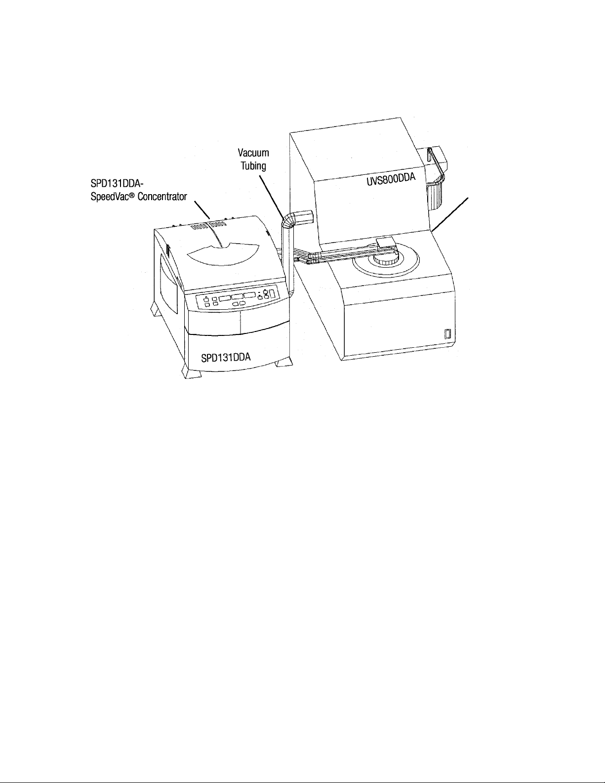
INSTALLATION OF THE SPD131DDA
Figure 4-Front View of System
UVS800DDA
Unviersal Vacuum Source
What it should look like:
How To Hook Up The SPD131DDA SpeedVac
1. Unpack unit from the box and verify that all the parts match packing list.
2. Read instruction manual carefully! If assistance is required, contact Customer Service.
3. If the unit is part of a larger system, use the vacuum tubing supplied to hook up unit (See Figure 4).
4. Vacuum clamps must be put on vacuum ports of pump and SPD unit (See item 8 on Figure 2 and
Figure 4).
5. If the unit is being connected to an existing system, attach vacuum tubing to various components as
illustrated above and in Appendix 1.
CAUTION - Cold trap should be in line between the vacuum source
and the SPD Unit.
®
System
3
Page 7

CONTROL PANEL
1
Pre-
Heat
RC
On/Off
3
Select
View
10
11
Modify Setpoints
12
Level
Ramp
Vacuu
m
7
Manual
Run
Auto
Run
8
2
9
4
5
6
Description of Control Panel
1. PRE-HEAT - use to pre-heat chamber to 45 °C prior to beginning or between runs.
Once run is initiated the pre-heat stops.
2. RC ON/OFF - Use to add radiant heat to chamber. Manually activate by pressing
ON/OFF at any point during run. Will activate as long as there is time left on the
heat timer. Will turn off when heat timer=0.00
3. SELECT - Press this button to select the parameters to be modified. Selection is
from left to right. GREEN light indicates the parameter to be modified.
4. MODIFY SET POINTS UP/DOWN - Modifies selected parameter.
5. VACUUM SET - (VACUUM CONTROLLER) - Selects either “Level” or “Ramp” in
the VAC display.
Level: Allows users to select a pre-set vacuum level. Once this level is obtained,
the microprocessor will regulate and maintain this vacuum level. The
vacuum level can be set from 20 torr to 100 mtorr.
Ramp:The rate at which vacuum is achieved can be set for preventing bumping.
5 adjustable levels can be set as required depending upon your solvent.
Setting Vacuum Rate (approximate
)
5 70 torr/min (Maximum setting)
4 50 torr/min
3 40 torr/min
2 30 torr/min
1 5 torr/min
6. AUTO RUN - Starts an ‘Automated’ run.
7. MANUAL RUN - Starts a “Manual” run.
8. STOP - Terminates “Manual” or “Auto” run.
9. VIEW - Press to view. Displays preset parameters when pressed during a run.
10. TEMPERATURE DISPLAY - Indicates set temperature or actual temperature
during a run in
°C.
4
Page 8

11. TIME DISPLAYS - Indicates heat timer or run timer set-points. In the
process of a run it indicates elapsed time or time left. Set from
0.01 [1 min.] to 9.59 [9 hours, 59 minutes] or “CCC” [continuous].
12. VACUUM PRESSURE DISPLAY - Displays vacuum level or ramp.
Chamber vacuum is displayed in torrs or millitorrs by shifting a decimal point.
“Hpr.” represents atmospheric pressure. No decimal point
indicates microns. Ramp can be set to five (5) adjustable levels.
NOTE - The unit will sound an audible beep, every time a button is pressed.
EXAMPLE OF A MANUAL RUN
1. Connect the unit to its required voltage.
2. The cover lock disengages, allowing the top cover to be opened.
The display lights up, showing the following default values:
Temperature: 45
°C in RED
RunTime: 2.00 HRS. in GREEN
Vacuum Pressure: 01.0 in AMBER
3. Using the “SELECT” button and the up/down keys, setTEMPERATURE
between 45
°C and 80 °C, or “no”, for no heat.
4. Using the “SELECT” button and the up/down keys select and modif
“HEATTIME” to between 0.01 and 9.59 hours or CCC (for continual
heating). When the heat timer expires, the heater will shut off, no
matter what the temperature setpoint reads (except if CCC).
5. Select Run Time: Since this a manual run no time adjustment is needed.
6. To select a VACUUM LEVEL, press “VACUUM SET” to illuminate LEVEL
and use th up/down keys to set vacuum to desired level. To select a
vacuum ramp rate, press “Vacuum Set” to illuminate RAMP and use the
up/down keys to set a ramp rate (5=highest, 1=lowest).
7. Place the sample tubes in the rotor and ensure that the load is balanced.
Secure rotor with the supplied knob. Close cover.
8. Pre-heat may be selected at this time, to warm chamber to 45
°C.
9. Press the “MANUAL RUN” button.The cover locks and rotor starts
turning. The decimal point blinks and the “RUN TIME” display counts up.
The temperature rises to the set temperature. The “HEAT TIME” will count
down and vacuum will be applied to the chamber.The vacuum level
begins falling.
NOTE: If the cover is not closed, the display will show “Lid” and the run
will not start.
5
Page 9

10. Press R/C for radiant chamber heat. Press at any time to turn OFF and ON.
(As long as there is time left in the heat timer).
11. To end the manual run, press “STOP” button.The display will show “End”, the
valves will click, isolating the chamber from the vacuum pump and also allowing
air to bleed into the chamber.
12. After the rotor stops spinning, the cover lock disengages and the display reverts
to last set parameters, and the unit will sound several audible beeps.
13. Open the cover and remove samples.
GENERAL:
press “VIEW” button and “SELECT”. The display will revert temporarily to set points.
During the run, display shows actual parameters. To check set parameters
EXAMPLE OF AN AUTO RUN
1. Refer to the “MANUAL RUN” section for start up.
2. To execute an AUTO “TIMED” RUN:
a) Use “SELECT” button and the up/down keys to select and modify
“TEMPERATURE, “HEATTIME, “RUN TIME” parameters. RUN and
HEATTIME can be set from 0.01 to 9.59 hours (HEATTIME also has
“CCC” for continuous use).
b) To set a VACUUM LEVEL, press “VACUUM SET” to illuminate
LEVEL up/down keys to set vacuum to desired level.
To select a vacuum ramp rate, press “Vacuum Set” to illuminate
RAMP and use the up/down keys to set a ramp rate (5=highest,
1=lowest).
3. Place the sample tubes in rotor so load is balanced. Secure rotor with
supplied knob. Close cover.
a) Press “AUTO RUN” button to start the run.The cover locks and the
rotor starts spinning.The time display is counting down in 1 minute
Intervals and the decimal point blinks. The heat time is counting
down (use select button to view “HEAT TIME”). The temperature
rises in 1
begins decrementing down from “HPr” (atmospheric pressure),
after both SAV valves actuate, applying vacuum to the chamber.
b) The vacuum display will indicate vacuum pressure in the chamber.
NOTE: If the cover is not closed, the display will show “Lid” and
the run will not start.
°C increments to set temperature.The vacuum pressure
6
Page 10

c) Press R/C for radiant chamber heat. Press at any time to turn OFF and
ON. (As long as there is time left in the heat timer).
d) Once the time decrements to 0.00 HRS. the run will automatically stop,
the display will show “End”,the SAV valves will click, also allowing air to
bleed into the chamber.
e) After the rotor stops spinning, the cover unlocks and the display reverts
to last set parameters, and the UNIT will sound several audible beeps.
f) Open the cover and remove samples.
GENERAL
press “VIEW” button and “SELECT”. The display will revert temporarily to set points.
: During the run, display shows actual parameters. To check set parameters
7
Page 11

Rotor Selection Guide
8
Page 12

GUIDELINES FOR SOLVENT CHOICE
Part I Solvents suited for the SPD 131 DDA unit
• Ethanol
• Methanol
• Formic Acid
• Water
• Acetonitrile
• Methylene Chloride
• Chloroform
• Ethyl Acetate
• Hydrochloric Acid
• Trifluoroacetic Acid
• DMSO (Special set-up required-see Appendix 2)
In the event that your choice of solvents and applications are unique and not listed above, please contact Customer
Support for advice.
MAINTENANCE/SERVICE
1. Maintenance: The SPD131DDA SpeedVac requires no scheduled maintenance.
2. Cleaning: The SPD131DDA SpeedVac should be cleaned if solvent, spills on or inside
the unit. Cl
Always wear gloves when cleaning and dispose used of paper
towel in appropriate designated refuse containers.
ean up any spills immediately using absorbent towels.
3. Replace chamber seal if cracked (Part number is 197-6020-01).
4. Outside of unit can be cleaned with di
5. For any other maintenanc
e or service issues or service problems, contact Customer Service
lute solution of soap and water.
.
9
Page 13

1
Page 14

SPECIFICATIONS
Model:
Bleeder Valve:
Temperature Range:
Volume Range/Tube:
Tube Capacity:
Maximum Carrier Capacity:
Dimensions: (W x D x H) in.:
cm:
Weight: lbs. (kg)
Power requirements:
SPD131DDA
Integrated Automatic Bleeder lve
45°
C-80°C
18 x 150 mm*
6*
2 x (96-deepwell plates)
14 x 18 x 13
36 x 45 x 33
31 (14)
115 VAC/60Hz, 5.0A (Part number
SPD131 DDA-115)
or 230 VAC/50Hz, 3.0A (Part
number SPD131 DDA-230)
All Thermo products mentioned in this manual (except glassware) are warranted against defects
in material and workmanship for one year after the date of delivery to the original purchaser.
Thermo’s warranty is limited to defective materials and workmanship, and does not cover
incidental or consequential damages. Warranty work is subject to our inspection of the unit.
No instruments, equipment, or accessories will be accepted without a Return Material
Authorization (RMA) number issued by Thermo. Costs of shipping the unit are not covered under
warranty. The warranty obliges you to follow the precautions in this manual. It is the responsibility
of the user to dispose of ALL materials in a manner in accordance with all federal, s ta te an d lo ca l
regulations. ALL RETURNED UNITS MUST BE DECONTAMINATED AND FREE O F
RADIOACTIVITY AND SHOULD BE ACCOMPANIED WITH A DECONTAMINATION FORM. PLEASE
CONTACT THERMO TO HAVE THIS FORM FAXED TO YOU!
Under no circumstances shall Thermo be liable for damages due to the improper handling or
use of its products. Thermo assumes no liability, express or implied, for your use of this
equipment.
* This is an example of volume range and tube capacities, please see page 6 for other tubes and capacities available.
11
Page 15

A
APPENDIX 1
Additional SPD 131 DDA System Set-ups
*Vacuum Tubing Carrying Vapors From
SPD131 DDA to RVT405DDA
*Vacuum tubing MUST be connected so that
there is no dips or bends that will collect
condensed DMSO.
SpeedVac® Concentrator
SPD131DDA
(Back view of Concentrator)
NT100
Exhaust recovery
post trap
UVS800DDA
Universal Vacuum Source
*Vacuum Tubing Carrying Vapors From
SPD131 DDA to RVT405DDA
*Vacuum tubing MUST be connected so that
there is no dips or bends that will collect condensed DMSO.
________________
SpeedVac® Concentrator
SPD131DDA
(Back view of Concentrator)
SEMI-INTEGRATED SYSTEM-HVSU131 DDA
Vacuum Tubing
From SPD131 DDA to
Vacuum Tubing From RVT405DD
to the RVT4104 Cold Trap
A
VLP80
Vacuum Tubing
From RVT4104 to
SPD131DD
A
COMPONENT HIGH VACUUM SYSTEM-HVS131 DDA
12
Page 16

APPENDIX 2
Additional SPD 131 DDA System Set-ups for DMSO Applications
SpeedVac® Concentrator
SPD131DDA
(Back view of Concentrator)
*Vacuum Tubing Carrying Vapors
From SPD131 DDA to RVT405DDA
*Vacuum tubing MUST be connected so
that there is no dips or bends that will
collect condensed DMSO.
SPD131DDA
RVT405DDA RVT4104
Vacuum Tubing From RVT405DDA
to the RVT4104 Cold Trap
Vacuum Tubing
Vacuum Tubing OFP400
From RVT4104 to
SPD131DDA
OFP400
From SPD131 DDA to
LOW VACUUM SYSTEM-LVS131 DDA
13
12
Page 17

APPENDIX 3
RS232 Port Specifications
Baud Rate: 9600
Parity : None
Bits: 8
Stop Bit: 1
Data Format:
*ALL X’s are numerals from 0-9.
X X__
repeats
The first field (XX) indicates temperature in
supplied.
The second field (X.XX) indicates heater time, hours.minutes. The display “C.CC” denotes a
continuous heat run. The display “E.nd” denotes the end of the heat run
The third field (X.XX) indicates run time, hours.minutes. The display “E.nd” denotes the end
of the run.
The fourth field indicates vacuum in torr units. If the vacuum is less than 1 torr, the format is
.XXX. If it is greater than 1 torr, the format is XX.X
For example:
56__
repeats)
This represents a temperature of 56
of 3 hours and 59 minutes and vacuum level of 15.8 torr.
(space) _X.XX(space) X.XX (space) __ XX.X(space) sequence
(space) _3.30 (space) __3.59 ________(space) 15.8 (space) (sequence
°C. The display “no” denotes no heat being
°C, a heater time of 3 hours and 30 minutes, a run time
Page 18

WEEE Compliance
WEEE Compliance. This product is required to comply with the European
Union’s Waste Electrical & Electronic Equipment (WEEE) Directive 2002/96EC.
It is marked with the following symbol. Thermo Fisher Scientific has contracted
with one or more recycling/disposal companies in each EU Member State, and this
product should be disposed of or recycled through them. Further information on
our compliance with these Directives, the recyclers in your country, and
information on Thermo Scientific products which may assist the detection of
substances subject to the RoHS Directive are available at www.thermo.com/
WEEE Konformittät. Dieses Produkt muss die EU Waste Electrical & Electronic
Equipment (WEEE) Richtlinie 2002/96EC erfüllen. Das Produkt ist durch
folgendes Symbol gekennzeichnet. Thermo Fisher Scientific hat Vereinbarungen
getroffen mit Verwertungs-/Entsorgungsanlagen in allen EU-Mitgliederstaaten
und dieses Produkt muss durch diese Firmen widerverwetet oder entsorgt werden.
Mehr Informationen über die Einhaltung dieser Anweisungen durch Thermo
Scientific, dieVerwerter und Hinweise die Ihnen nützlich sein können, die Thermo
Fisher Scientific Produkte zu identizfizieren, die unter diese RoHS.
Anweisungfallen, finden Sie unter www.thermo.com/
Great Britain
Deutschland
Conformità WEEE. Questo prodotto deve rispondere alla direttiva dell’ Unione
Europea 2002/96EC in merito ai Rifiuti degli Apparecchi Elettrici ed Elettronici
(WEEE). È marcato col seguente simbolo.Thermo Fischer Scientific ha stipulato
contratti con una o diverse società di riciclaggio/smaltimento in ognuno degli Stati
Membri Europei. Questo prodotto verrà smaltito o riciclato tramite queste
medesime. Ulteriori informazioni sulla conformità di Thermo Fisher Scientific con
queste Direttive, l’elenco delle ditte di riciclaggio nel Vostro paese e informazioni
sui prodotti Thermo Scientific che possono essere utili alla rilevazione di sostanze
soggette alla Direttiva RoHS sono disponibili sul sito www.thermo.com/
Conformité WEEE. Ce produit doit être conforme à la directive euro-péenne
(2002/96EC) des Déchets d’Equipements Electriques et Electroniques (DEEE). Il
est marqué par le symbole suivant. Thermo Fisher Scientific s’est associé avec une
ou plusieurs compagnies de recyclage dans chaque état membre de l’union
européenne et ce produit devraitêtre collecté ou recyclé par celles-ci. Davantage
d’informations sur laconformité de Thermo Fisher Scientific à ces directives, les
recycleurs dans votre pays et les informations sur les produits Thermo Fisher
Scientific qui peuvent aider le détection des substances sujettes à la directive
RoHS sont disponibles sur www.thermo.com/
Italia
France
Page 19

Important
For your future reference and when contacting the factory, please have the
following information readily available:
Model Number:
Serial Number:
Date Purchased:
The above information can be found on the dataplate attached to the
equipment. If available, please provide the date purchased, the source of
purchase (manufacturer or specific agent/rep organization), and purchase
order number.
IF YOU NEED ASSISTANCE:
SALES DIVISION
Phone: 1-866-984-3766
1-866-9-THERMO
LABORATORY PARTS and SERVICE
Phone: 1-800-438-4851
TECHNICAL SUPPORT
Phone: 1-800-438-4851
Page 20

Thermo Fisher Scientific Inc.
275 Aiken Road
Asheville, NC 28804
United States
www.thermofisher.com
197-3003-00 Rev G
 Loading...