

Page 1
Operating Instructions DB-055-210904 E
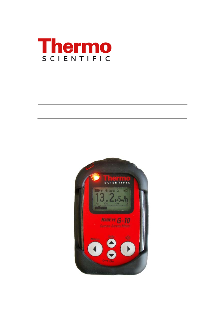
RadEye G-10
Portable Dose- and Dose Rate Meter
Page 2

Page 3

REVISIONS SHEET:
Rev. Rev.
state
24.06.05 RM&P-E Tr
A
11.07.05 RM&P-E Tr 0-5, 2-5,
B 18.08.05 RM&P-M Iw Chap. 6
Dept.
resp.
Name Rev.
page
2-6, 3-2
3-5, 4-1,
4-4, 4-5,
6-13
Cat.
Explanation
*)
C 28.09.05 RM&P-E Tr 2-3, 2-5
5-2
7-7
D
04.07.06 RM&P-EH Pi cpl. A V 1.16 new
E 06.10.06 RM&P-EH Pi 8-8 A > V 1.18
F
17.07.07 RM&P-E Tr 8-1
G
20.08.08 RM&P-EH Pi cpl. A > V 1.50
H
22.01.10 RM&SI-EH Pi 3-5;8-9 A > V 1.52
8-6, 8-7
A
RTC-Reset
A
Error Codes
V 1.08
Menu function
date format acc.
to ISO 8601
A Measuring range
Diagram 8-1 - 8-4
> V 1.22
Low Battery warning
Set Date/Time
Trend indication
*) Category C: editorial correction
I: clearing improvement
A: substantial amendment
Explanations must be given, at least with Category A.
RadEye G-10 DB-055-210904 E 0-1
Iw/Tr/Ff 22.01.2010
Page 4

CONTENTS:
1. Introduction......................................1-1
2. Installation and start-up.................. 2-1
2.1 Scope of delivery ......................................................2-1
2.2 Inserting the battery ..................................................2-5
2.3 Mounting of the protection sleeve ............................2-7
2.4 Switching the unit on ................................................2-8
3. Configuration................................... 3-1
3.1 Menu functions .........................................................3-1
3.2 Basic display .............................................................3-4
3.2.1 Trend indication.................................................3-5
3.3 Alarm thresholds.......................................................3-6
3.4 Setting alarm thresholds............................................3-6
0-2 DB-055-210904 E RadEye G-10
Iw/Tr/Ff 22.01.2010
Page 5

4. Operation..........................................4-1
4.1 Audible single pulse indication and finder mode......4-1
4.2 Alarm indication .......................................................4-2
4.3 Additional information .............................................4-3
4.4 Key Lock ..................................................................4-4
4.5 Process description for detection of radiation sources.4-5
4.6 Earphone ...................................................................4-6
4.7 Alarm latching ..........................................................4-7
4.8 Show alarm ...............................................................4-8
4.9 Text Info ...................................................................4-9
4.10 Display rotation.....................................................4-9
4.11 Set Date and Time...............................................4-10
4.12 Battery type .........................................................4-10
RadEye G-10 DB-055-210904 E 0-3
Iw/Tr/Ff 22.01.2010
Page 6

5. Functional test................................. 5-1
5.1 Functional test...........................................................5-1
5.2 Failure indication ......................................................5-1
5.3 Overload indication...................................................5-3
5.4 Low Battery ..............................................................5-4
6. PC configuration..............................6-1
6.1 Main menu ................................................................6-2
6.1.1 RadEye G-10 Device Parameters ......................6-3
6.1.2 Measurements....................................................6-4
6.1.3 Creating a Measurement File.............................6-5
6.1.4 Select serial interface.........................................6-7
6.2 Configuration ............................................................6-7
6.3 History ....................................................................6-12
6.4 Logbook..................................................................6-14
6.4.1 Messages in the logbook-file...........................6-15
7. RadEye inductive charger...............7-1
7.1 LED indicators..........................................................7-2
0-4 DB-055-210904 E RadEye G-10
Iw/Tr/Ff 22.01.2010
Page 7

8. Technical data..................................8-1
8.1 RadEye G-10.............................................................8-1
8.2 RadEye inductive charger .........................................8-5
8.3 Firmware revisions ...................................................8-8
V1.08................................................................................8-8
V1.16................................................................................8-8
V1.18................................................................................8-8
V1.20................................................................................8-9
V1.21................................................................................8-9
V1.22................................................................................8-9
V 1.50...............................................................................8-9
V1.52................................................................................8-9
RadEye G-10 DB-055-210904 E 0-5
Iw/Tr/Ff 22.01.2010
Page 8

TABLE OF FIGURES:
Diagram 8-1: Energy dependence in direction of max.
response, perpendicular to ref. mark ...........................8-6
Diagram 8-2: Angular response, horizontal plane..............8-6
Diagram 8-3: Angular response, vertical plane..................8-7
Diagram 8-4: Statistical standard deviation of the measured
value with constant dose rates.....................................8-7
SAFETY INSTRUCTIONS
Due to the rather high detector sensitivity the dose rate measuring range of the RadEye G-10 is limited to 100 mSv/h.
A correct dose integration is performed only, if the instrument
does not display over load “OVERLOAD”
The RadEye G-10 is suited to perform highly accurate dose
measurements at low to medium dose rates. It is however not
intended for use as a legal personal dose meter.
The RadEye G-10 is not well suited for pulsed radiation.
There will be a significant under estimation at dose rates during pulse of more than 0,2 R/h.
Do not use the unit if error messages appear on the screen.
The earphone connector at the bottom side of the instrument
must be exclusively used by equipment that is specified for
use with RadEye G-10.
0-6 DB-055-210904 E RadEye G-10
Iw/Tr/Ff 22.01.2010
Page 9
WEEE Compliance:
This product is required to comply with the European Union’s
Waste Electrical & Electronic Equipment (WEEE) Directive
2002/96/EC. It is marked with the following symbol:
Thermo Fisher Scientific has contracted with one or more
recycling/disposal companies in each EU Member State, and
this product should be disposed of or recycled through them.
Further information on Thermo Fisher Scientific compliance
with these Directives, the recyclers in your country, and information on Thermo Fisher Scientific products which may
assist the detection of substances subject to the RoHS Direc-
tive are available at www.thermo.com/WEEERoHS
RadEye G-10 DB-055-210904 E 0-7
Iw/Tr/Ff 22.01.2010
Page 10

Page 11

1. Introduction
The pocket sized RadEye G-10 is a sensitive and rugged device to measure the ambient equivalent dose rate (Sv/h) of
gamma and X-ray radiation.
The characteristic feature of the RadEye G-10 is the use of
sophisticated low power technology components and microprocessor based, fully automatic self checks. No maintenance
is required.
The RadEye G-10 incorporates a sensitive GM tube detector
allowing the detection of low to medium radiation levels.
The last 1600 mean and maximum values of the dose rate and
count rate are recorded internally and can be read out via serial
interface.
Additionally the RadEye G-10 logs the last 250 alarms, errors
and changes of the configuration. All events can be read out
via serial interface.
A real time clock is provided to add a time stamp to all buffer
data.
RadEye G-10 DB-055-210904 E 1-1
Iw/Tr/Ff 22.01.2010
Page 12

All or selected menu functions described in 3.1 can be configured to be invisible and inaccessible by the user.
Thus the instrument can be configured to both, an extremely
simple mode allowing just LCD-illumination and alarm acknowledgment to a very versatile mode for the more experienced user.
Alarm LED, showing radiation exceeding thresholds.
Visible from top if
worn in a holster
and from display
side
Rugged plastic enclosure
Key on top side to acknowl-
edge alarms if worn in a holster
Powerful graphical display
Easy to use, four key,
menu driven user interface
Earphone connector
1-2 DB-055-210904 E RadEye G-10
Iw/Tr/Ff 22.01.2010
Page 13
2. Installation and start-up
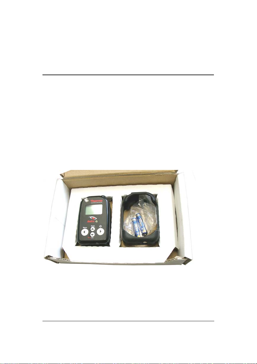
2.1 Scope of delivery
The RadEye G-10 is delivered in a folding paper box together
with two AAA cells and an operating manual.
A rubber protection sleeve, a holster and an earphone may be
added optionally.
RadEye G-10 DB-055-210904 E 2-1
Iw/Tr/Ff 22.01.2010
Page 14
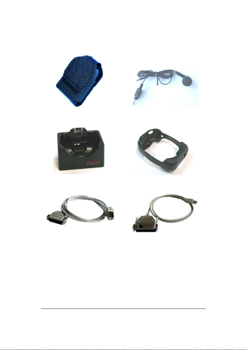
Ordering information for accessories:
Holster
42506/7046
Desktop holder
42506/7060
RS232-adapter cable
42540/29
Earphone
42506/7037
Rubber sleeve
42506/7030-18
USB- adapter cable
42540/26
2-2 DB-055-210904 E RadEye G-10
Iw/Tr/Ff 22.01.2010
Page 15
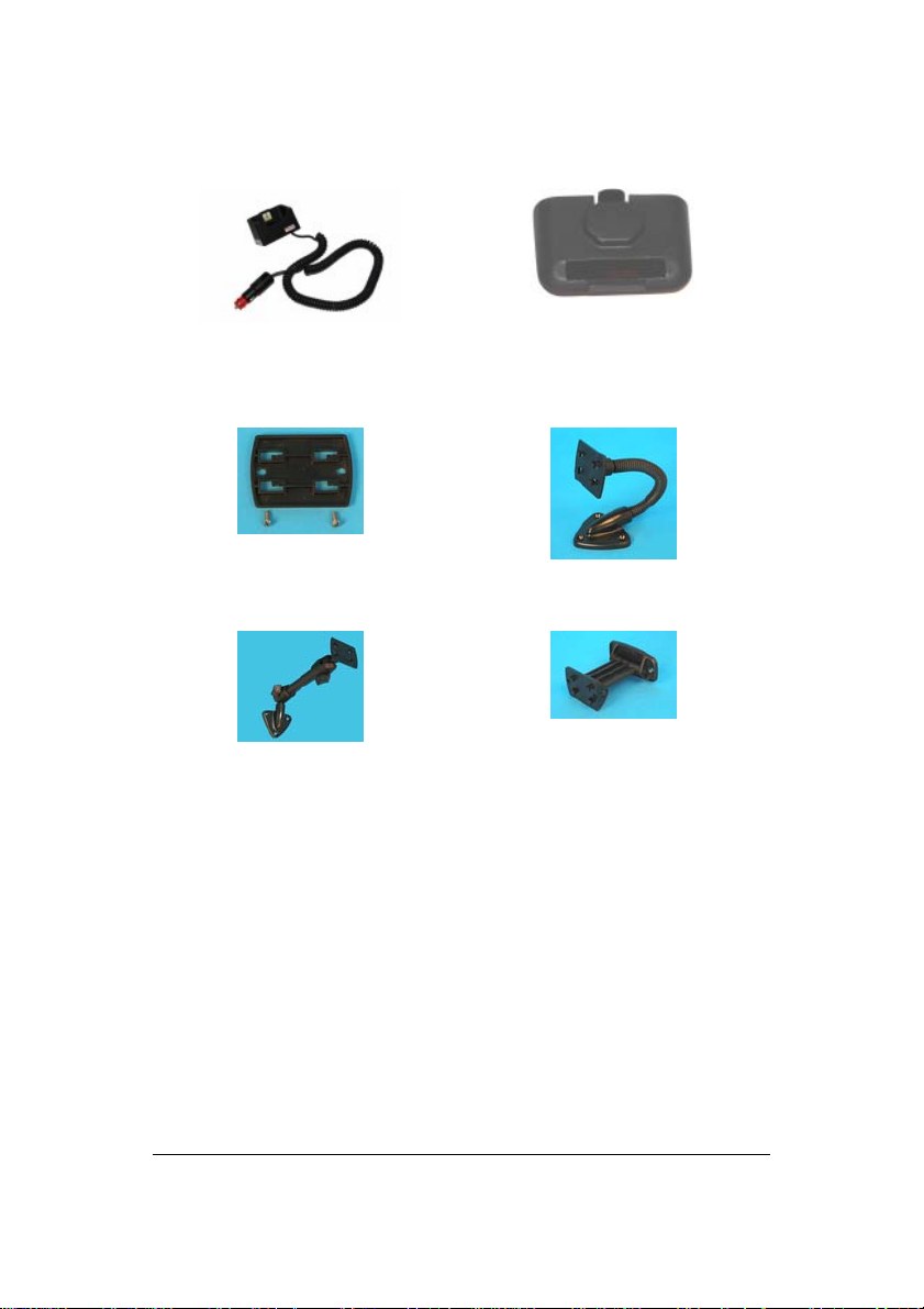
Inductive charger
42506/7080
Flat mounting kit
42506/7059
Pivot arm adaptor kit
42506/7062
Battery lid for inductive
charger
42506/7034
Goose neck adaptor kit
42506/7061
Knuckle joint adaptor kit
42506/7063
RadEye G-10 DB-055-210904 E 2-3
Iw/Tr/Ff 22.01.2010
Page 16
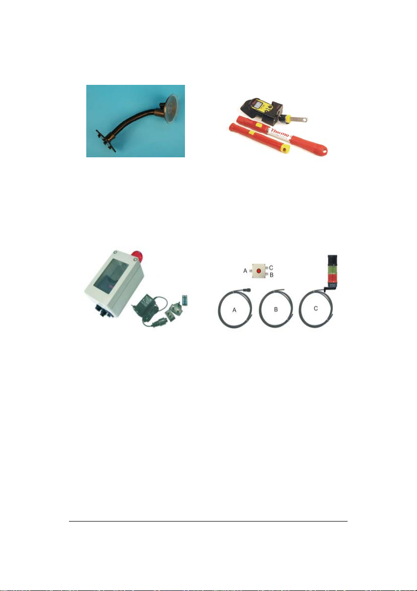
Goose neck adaptor kit with
suction cup
42506/7064
Telescopic adapter:
RadEye adapter 42506/7078
Handle 0,35m 42506/7075
Handle 1,2m 42506/7076
Handle 4m 42506/7077
RadEye Area Monitor
42506/80
2-4 DB-055-210904 E RadEye G-10
Iw/Tr/Ff 22.01.2010
External alarm unit for RadEye area monitor
42506/8010
Page 17
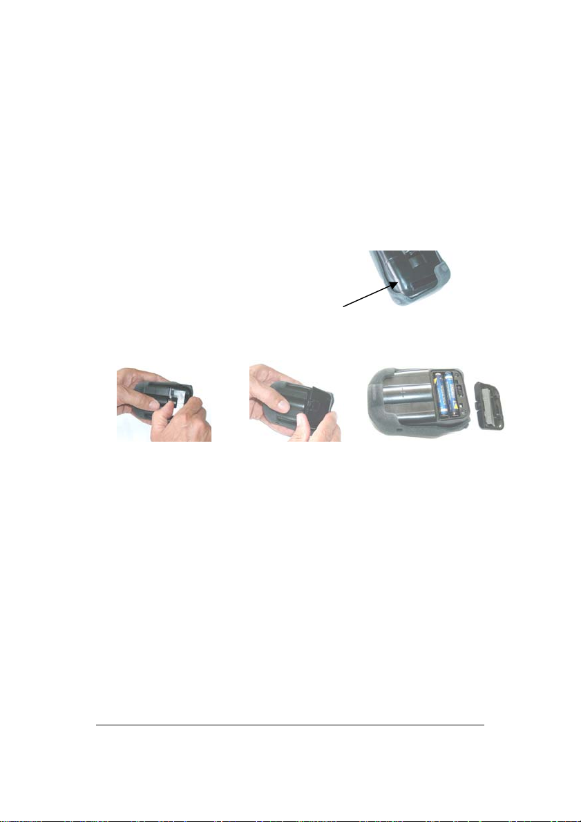
2.2 Inserting the battery
The two AAA-Alkaline cells as delivered with the instrument
allow up to 500 h of normal operation.
AAA size rechargeable batteries can be used as well.
• Switch off the measuring instrument.
• If supplied, remove rubber sleeve.
• Open the cover of the battery compartment.
Use of a coin is recommended.
• Exchange the batteries according to the shown polarity.
• Close the compartment cover, hooks first, care for the rub-
ber seal being in it’s groove.
• Switch on the unit again. (see chapter 2.4)
The instrument continues working in the operating mode set
last (see chapter 3.2).
RadEye G-10 DB-055-210904 E 2-5
Iw/Tr/Ff 22.01.2010
Page 18

The measured values in the history memory remain stored.
The real time clock for time stamp of history values and logbook continue operation, if batteries are exchanged without
delays. If Real Time Clock is set, actual time and date is displayed for 3 s.
To keep RTC running during battery exchange, batteries must
be exchanged without delays.
RTC will always be reset, if instrument is stored without batteries for more than 10 seconds.
History data and measurement parameters are stored permanently, even if batteries are removed.
RTC information is only required, if the instrument is
switched off and on during operation and if correct timing
information for history and logbook entries is needed.
For the last power on interval, the relative time information of
logbook and history is corrected to actual PC clock time during read out. In these cases the setting of the clock is not required.
2-6 DB-055-210904 E RadEye G-10
Iw/Tr/Ff 22.01.2010
Page 19

2.3 Mounting of the protection sleeve
The rubber protection sleeve improves ruggedness to mechanical shocks.
For mounting of the sleeve first put the instrument into the top
of the sleeve. Then pull lower edges of the sleeve, one after
the other into it’s right position.
First step Second step
Front view Rear view
RadEye G-10 DB-055-210904 E 2-7
Iw/Tr/Ff 22.01.2010
Page 20
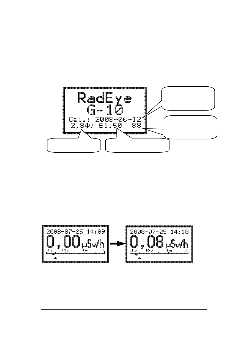
2.4 Switching the unit on
To switch on the RadEye G-10, keep the ON button pressed for
at least one second. The sound generator (beeper) is initiated.
Calibration
date
Checksum of
Firmware version Battery voltage
The RadEye G-10 starts working with the parameters previously selected (operation mode, calibration factor alarm
thresholds etc.).
If the real time clock is set, actual date and time is displayed
for 3s. The RadEye G-10 first displays 0.00 µSv/h. After the
first detector pulse the measurement will be started.
the firmware
Unless otherwise specified by the customer when placing the
order, the following values are set by the factory before delivery:
2-8 DB-055-210904 E RadEye G-10
Iw/Tr/Ff 22.01.2010
Page 21

Alarm 1 for Dose Rate
Alarm 2 for Dose Rate
Alarm 1 and 2 for the Dose
0.5 µSv/h
25.0 µSv/h
app. 16 Sv
Acoustic alarm (Sound) active
LED alarm indication active
Vibrator alarm indication active
Acoustic count rate indication Single Pulse
Autosend off
History recording interval 120 s *)
*) These parameters can only be changed through the serial
interface by means of the configuration software.
The first alarm thresholds for dose rate is around 200 - 500 %
above the typical normal background and allow sensitive, but
false alarm free dose rate monitoring with a reasonable fast
response time. The alarm thresholds for the dose are set to the
maximum possible values, thus being deactivated. With the
setting of the history recording interval of 120 s , the last 52
hours of operation will be stored in the history memory.
These default values are reasonable for the majority of applications. For special applications the parameters (except calibration parameters) can be changed with the help of the optional PC-program „RadEye.EXE“ and the cable 42540/29.
Furthermore, additional monitoring modes can be activated.
The calibration parameters can only be changed in the factory
using special software tools.
RadEye G-10 DB-055-210904 E 2-9
Iw/Tr/Ff 22.01.2010
Page 22

Page 23
3. Configuration
3.1 Menu functions
To enter the operating menu press the “Menu” key.
Scrolling through the single menu options is effected by the up
/ down arrow keys.
The display returns to its initial default setting in case no key
has been activated for more than 10 seconds.
A
j to be found behind some menu options means that the
respective function is active.
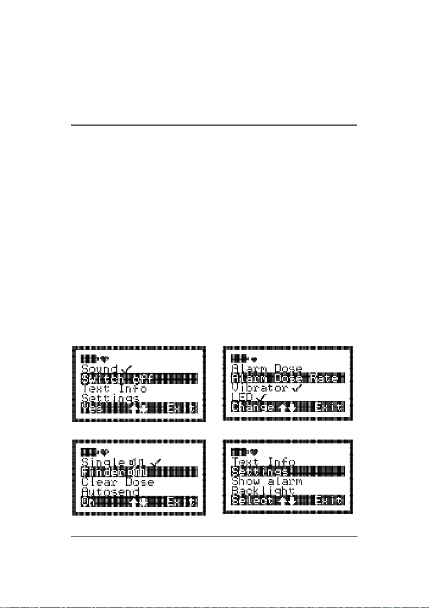
The menu offers the following displays:
RadEye G-10 DB-055-210904 E 3-1
Iw/Tr/Ff 22.01.2010
Page 24

The above illustration depicts all menu options available or
possible
Using the PC-Software and an interface adapter, any of the
functions can be hidden. This allows the user to be given only
the functions necessary to accomplish his measurement duties,
thus simplifying the handling considerably.
The Up- and Down arrow key are used to scroll through the
menu.
To select a menu option, release the left key as the respective
menu option has been reached.
The meaning of the Menu key may change with the selected
menu. The meaning is shown on the bottom of the display.
Change: Edit Alarm values
Off, On: Switching a function on and off
Select: Select a default display mode
Yes: Confirmation of an action
Exit: Exit menu
In Change menu the Up-/Down arrow keys are used to change
a digit of an alarm value.
3-2 DB-055-210904 E RadEye G-10
Iw/Tr/Ff 22.01.2010
Page 25

MENU DISPLAY DESCRIPTION OF THE FUNCTION ACTIVATED
Sound
BY THE LEFT KEY
Switching the acoustic alarm and the audible indication
of keystrokes on/off
Switch off
Single Pulse Enabling and disabling of single pulse indication. Acti-
Finder Enabling and disabling of audible radiation intensity.
Clear Dose Clears accumulated dose
Alarm Dose
Alarm Dose Rate Allows setting of dose rate Alarm1 and 2 (Sv/h).
LED
Vibrator
Autosend If activated, the instrument sends a data string periodi-
Backlight Backlight always on/Backlight extinguish after 10 s.
Show Alarm Display of alarms stored in alarm log.
Settings - Switching between battery type Battery and Accu. It is
Text Info Displays a text stored in the RadEye.
RadEye is switched off.
Time and stored data are maintained.
vation is done by audio keys (right button and top button).
Activation is done by audio keys (right button and top
button).
Allows setting of dose alarm 1 and 2
Switching the optical alarm on/off
Switching the vibration alarm on/off
cally to the infrared port.
This is used for radio transmission units.
used for the correct warning of low battery.
- Set date and time of the real time clock.
RadEye G-10 DB-055-210904 E 3-3
Iw/Tr/Ff 22.01.2010
Page 26

3.2 Basic display
t
The standard display is indication of the actual dose rate .
Battery indication
Bar graph
overview
Pressing the up arrow/dose – key shows upon the
st
- 1
click: the accumulated dose (Sv)
Additionally the remaining time until the
dose alarm 1 is reached, assuming the current
dose rate will persist.
nd
- 2
click: the mean value and max value of the measured
dose rate, together with the time
indicated since the last reset..
rd
- 3
click: standard display
After 10 seconds or after 3
rate indication is activated again.
Heart bea
Measurement
rd
click standard display with dose
value
3-4 DB-055-210904 E RadEye G-10
Iw/Tr/Ff 22.01.2010
Page 27

st
1
click 2nd click
3.2.1 Trend indication
A trend indication is given, if the measured dose rate is increasing or decreasing.
For accurate measurements, only readings without trend indication should be used.
A trend indication is not given at dose rates of less than
0,6 μSv/h
RadEye G-10 DB-055-210904 E 3-5
Iw/Tr/Ff 22.01.2010
Page 28

3.3 Alarm thresholds
There are two alarm thresholds each allocated to dose and
dose rate.
In order to avoid dose alarms while using the instrument exclusively as a rate meter, the dose alarms can be set to the
maximum level.
Configuration of the alarms is possible via infrared interface
(chapter 6.2) or via the menu.
As to the alarm activation, please also read chapter 4.2.
3.4 Setting alarm thresholds
The menu options Alarm Dose Rate and Alarm Dose
allow the alarm thresholds to be modified. For this setting, the
user has 255 seconds time. Changing the value is effected by
pressing the left (Change) button if the corresponding “Alarm”
is selected:
To increment the number, press the up/down arrow keys. To
go on to the next digit or to quit the edit mode, menu use
right/left arrow keys.
Once the last number has been set, quit the editing mode by
pressing the “Exit”-key. Then, the value set is saved and after
10s the unit returns to the basic display.
Example:
3-6 DB-055-210904 E RadEye G-10
Iw/Tr/Ff 22.01.2010
Page 29

The dose rate alarm threshold must be changed.
Press “Menu” key, and up/down
arrow keys until
Alarm Dose Rate is selected
Then enter change menu by pressing “Change” key.
Edit value by pressing up / down
keys
select digit by left / right keys
Pre unit “μ”, “m” may be chosen as
well.
Leaving the last digit with the right
arrow key:
Confirm storage of edited value
pressing “yes”
The set points of the actual dose rate alarm thresholds is seen
at the marks on the intensity bar scale. The upper mark shows
alarm threshold 1, the lower mark shows alarm threshold 2
RadEye G-10 DB-055-210904 E 3-7
Iw/Tr/Ff 22.01.2010
Page 30

Page 31

4. Operation
4.1 Audible single pulse indication and finder mode
With the single pulse indication being selected, each
pulse of the detector generates a short audible signal emitted
by the beeper.
An audible alarm signal caused by exceeding the alarm threshold is not given while single pulse indication of finder mode is
active.
The single pulse indication must be enabled in the menu.
It is activated and deactivated by two times pressing the right or
top button:
Indication of activated
single pulse indication.
RadEye G-10 DB-055-210904 E 4-1
Iw/Tr/Ff 22.01.2010
Page 32

Finder mode:
In the Finder mode, the sound frequency depends on the pulse
rate of the detector. The more detector pulses above the count
rate that is present at the moment of the activation of the finder
mode are captured by the detector, the higher the tone.
The finder mode must be enabled in the menu.
It is activated and deactivated by two times pressing the right or
top button:
Indication of activated
finder mode.
4.2 Alarm indication
Each time the first alarm threshold is exceeded, the alarm devices beeper, LED and the vibrator become active, if they are
enabled.
Alarm 1: LED slowly blinking, two frequency alarm tone
Alarm 2: LED quick blinking, continuous alarm tone
Dose Alarm: LED constantly on, continuous alarm tone, vi-
brator slow.
4-2 DB-055-210904 E RadEye G-10
Iw/Tr/Ff 22.01.2010
Page 33

The alarm tone and vibrator are acknowledged by a short key
depression, the LED remains pulsing. The alarm is extinguished, when the first alarm threshold is remained under.
4.3 Additional information
In addition to the basic display, using the menu options, requests for further information can be started such as e.g. the
setting of the enabling and disabling of the various alarm indicators.
RadEye G-10 DB-055-210904 E 4-3
Iw/Tr/Ff 22.01.2010
Page 34

4.4 Key Lock
Pressing the “on/arrow down” key for at least 3 seconds, locks
the key pad:
It is recommended to lock the keys when wearing the unit in
the holster. Thus reduced battery time because of additional
power consumption by illumination of the LCD or other unintended operations is avoided.
Unlocking is performed according to the LCD instructions
upon pressing any key:
Press left key first, then lower key and then right key.
4-4 DB-055-210904 E RadEye G-10
Iw/Tr/Ff 22.01.2010
Page 35

4.5 Process description for detection of radiation
sources.
Direction of maximum response
To detect hidden radiation sources, the dose rate alarm threshold must be set to the lowest value, that does not produce fail
alarms. This is typical a value of 0,3 µSv/h to 0,5 µSv/h.
Due to it’s almost 100 times higher efficiency, the RadEye
PRD is more suited for this task, than the RadEye G-10.
Subsequently, the operator passes the object while keeping
thereby the distance between the monitor and the object to be
checked as small as possible.
With an alarm occurring, the operator should move the instrument while observing the display in order to localize the
position of the source. Please note, that the alarm can occur up
to a few seconds after passing the nearest distance to the
source.
If the alarm disappears after a few seconds, this alarm is to be
considered as a statistically released false alarm.
In case a radiation source has been detected, the radiation intensity is indicated. (see chapter 3.2).
RadEye G-10 DB-055-210904 E 4-5
Iw/Tr/Ff 22.01.2010
Page 36

4.6 Earphone
For alarming in noisy environments or for undercover investigations an earphone is available. See ordering information
page 2-1.
The earphone is connected at the bottom of the instrument
after opening the rubber protection seal.
4-6 DB-055-210904 E RadEye G-10
Iw/Tr/Ff 22.01.2010
Page 37

4.7 Alarm latching
Via PC-program it is possible to configure a alarm latching.
Alarm latching means the alarm is stored for the configured
time from 0 s (= off) to 9999 s.
A latched alarm is indicated by a “M” near by the alarm indicator. When the alarm is acknowledged the RadEye returns to
normal operations.
Latching indication
RadEye G-10 DB-055-210904 E 4-7
Iw/Tr/Ff 22.01.2010
Page 38

4.8 Show alarm
By selecting the menu point “show alarm” the alarms stored in
the alarm log are displayed together with the time of alarm and
the actual time.
By pressing the up and down arrow keys you can scroll
through the alarm log. By pressing the right button the display
returns to the menu.
Actual time of the Real
Time Clock
Stored alarm
Time of the stored alarm
4-8 DB-055-210904 E RadEye G-10
Iw/Tr/Ff 22.01.2010
Page 39

4.9 Text Info
Via PC program „RadEye.exe“ it is possible to place a text
information in the RadEye. This text information can be displayed with the menu function „Text Info“.
4.10 Display rotation
If enabled, a short press on the lower centre key (arrow down)
flips the display. If the lower centre key is pressed again or if
the menu button is pressed, the screen flips into the normal
orientation.
RadEye G-10 DB-055-210904 E 4-9
Iw/Tr/Ff 22.01.2010
Page 40

4.11 Set Date and Time
Setting of date and time takes place via menu function Setting
→ Set Date/Time.
The setting use the format YYYY-MM-DD hh:mm. The fields
are selected with the keys right/left. With the keys up/down
the Year, month, day, hour or minute can be changed. After
setting the date and time the real time clock is set and is used
for alarm logbook and history.
4.12 Battery type
Selection of battery type: Rechargeable or non-rechargeable
batteries. It is needed for correct low battery warning. Type
“Batt” has a threshold of 2.1V. Type “Accu” has a threshold of
2.35V. See also chapter 5.4.
Battery type “Battery” Battery type “Accumulator”
4-10 DB-055-210904 E RadEye G-10
Iw/Tr/Ff 22.01.2010
Page 41

5. Functional test
The radiation meter performs continuous self-check routines.
A complete failure of the detector will be detected in around 2
minutes and will be indicated on the LCD and be announced
by the beeper. The same applies to the battery voltage.
5.1 Functional test
To carry out a simple test, shortly press any key. A short audible pulse has to be released and the LC display is illuminated
for some seconds.
The heart symbol next to the battery indicator must be “beating”. This indicates that the cyclic tasks as calculating measurement values, and checking for alarm thresholds are active.
5.2 Failure indication
In case of a failure the beeper generates a sharp single pulse
every 32 s.
The corresponding failure message is displayed in the LCD:
RadEye G-10 DB-055-210904 E 5-1
Iw/Tr/Ff 22.01.2010
Page 42

Error high voltage generation
No detector pulse within 128 seconds
EEPROM with calibration data shows
EEPROM Read and EEPROM Write
error.
A Watchdog Error indicates, that the
micro controller has problems to work
on it’s tasks in a given timeframe.
Reasons are strong electromagnetic
pulses, firmware errors or hardware
issues.
5-2 DB-055-210904 E RadEye G-10
Iw/Tr/Ff 22.01.2010
Page 43

5.3 Overload indication
On dose rates of more than 100 mSv/h an overload indication
is given:
Overload indication in dose rate display
The dose value is marked with an overload indication, if a
dose rate overload occurred since the last dose reset.
Overload indication
in dose display
RadEye G-10 DB-055-210904 E 5-3
Iw/Tr/Ff 22.01.2010
Page 44

5.4 Low Battery
If the battery voltage is below the configured threshold (see
chapter 4.12) the following warning appears:
The beeper generates a single pulse every 32s. This acoustic
warning can be suppressed by pressing the alarm acknowledge
key. After 8h this warning comes up again. The battery needs
to be changed. However, the RadEye can still be operated for
several hours.
If the battery voltage falls below 2V, the battery symbol starts
flashing. An acoustic warning is generated every 8s and can’t
be acknowledged. The battery needs to be changed as soon as
possible.
5-4 DB-055-210904 E RadEye G-10
Iw/Tr/Ff 22.01.2010
Page 45

6. PC configuration
RadEye desktop holder: 42506/60
IR adaptor cable RS232: 42540/29
RadEye G-10 DB-055-210904 E 6-1
Iw/Tr/Ff 22.01.2010
IR adaptor cable USB: 42540/26
Page 46

If there is a faulty connection between the unit and the computer, the program shows the error message “Data transfer to
instrument fails”
In this case, you must check whether:
• the unit has been connected;
• the unit has been switched on;
• the infrared transmission window at the unit and at the
transmission unit are clean;
• the correct serial interface has been selected.
Select the required interface, press OK to acknowledge the
error message. In the window that is displayed now, select the
Configuration / Com settings... menu.
6.1 Main menu
Once the RadEye.EXE program has been started, device parameters are displayed on the screen.
6-2 DB-055-210904 E RadEye G-10
Iw/Tr/Ff 22.01.2010
Page 47

6.1.1 RadEye G-10 Device Parameters
The Frame "RadEye G-10" contains the unit's serial number
and version number of the software. Click on the Read button,
the Parameters of RadEye G-10 will be read out from device
and shown in the Frame.
Figure 6-1: Main Window
RadEye G-10 DB-055-210904 E 6-3
Iw/Tr/Ff 22.01.2010
Page 48

6.1.2 Measurements
After pressing the button Read Values the current Count rate,
dose rate and dose are displayed in this frame.
With button Start the measured value is read from the unit at a
certain polling interval. Use the scroll bar or the buttons beneath the "polling interval" field to define the polling interval.
You can select a value between 1 and 3600 seconds.
The dose rate can be displayed numerically and graphically.
Click on the Graphics…. A diagram is displayed that gives a
representation of the dose rate values versus the time.
The current measured value is added at the right-hand side,
and the diagram is shifted to the left. Up to 100 measured values can be represented. The graduation of the ordinate is
automatically adjusted to the measured values supplied by the
unit.
Figure 6-2: Measurement graphics
6-4 DB-055-210904 E RadEye G-10
Iw/Tr/Ff 22.01.2010
Page 49

6.1.3 Creating a Measurement File
The actual measured values Count rate and Dose rate that are
shown in the "Measurement" display field can be stored in a
measurement file.
To do this, open the File menu, click on Open Logfile..., and
enter path and name. The file is stored with the file name extension ".log".
If another file of the same name exists, the system asks
whether that file shall be overwritten or the new measured data
shall be appended to the existing data.
Once you have pressed OK to confirm the entries, the measurement logfile is created and the polling measured data is
stored in the scan interval you have defined. An open measurement file is indicated by the name and the path of the
measurement logfile that appears in the top right-hand corner
of the window.
To terminate data storage, open the File menu and select the
Close Logfile menu item. No further data is recorded.
Open the File / View Logfile... menu to view the measurement
logfile.
For training and demonstration a prior recorded logfile can be
replayed by opening Replay logfile.
RadEye G-10 DB-055-210904 E 6-5
Iw/Tr/Ff 22.01.2010
Page 50

With the buttons Start and Stop together with the polling in-
terval the replay can be controlled.
Close Replay switches back to accessing measurement values
via infrared interface.
The measurement logfile is an ANSI text file with columns
that are separated by <TAB>. This enables this file to be read
easily into other programs (such as Excel) where the data can
be processed.
The first line of the measurement logfile contains the unit
name, the file name, and the path. Serial number and Device
identification are specified on the second line.
Date and time of the measurement are specified in the columns
under the field names "mm.dd.yy" and "hh:mm:ss". The time
setting corresponds to the PC system time.
The "Counter" column contains the numerical value of the
counter measurement. The "Unit" column informs about the
unit. The "Dose Rate" column contains the numerical value of
the dose rate measurement. The "Unit" column informs about
the unit (Sv/h or R/h).
6-6 DB-055-210904 E RadEye G-10
Iw/Tr/Ff 22.01.2010
Page 51

6.1.4 Select serial interface
Via Configuration / Com settings... menu another window is
opened from which you may select the corresponding interface. An error message is displayed if the interface is not
available.
6.2 Configuration
On the Configuration / RadEye G-10… menu, the following
parameters can be modified:
• Unit
• Time interval of the history
• Acoustic indication
• Alarm level for all basic displays
• Signalling types
• Additional surveillances
• active menu functions
RadEye G-10 DB-055-210904 E 6-7
Iw/Tr/Ff 22.01.2010
Page 52

Figure 6-3: General configuration
On the „Generals“ tab, the user may set the physical unit (Roentgen or Sievert), the time interval for the history memory
(1...43200s), the kind of the acoustic rate indication (single
pulse, finder 4.1) and temperature.
6-8 DB-055-210904 E RadEye G-10
Iw/Tr/Ff 22.01.2010
Page 53

Figure 6-4: Text
On the tab „Text“ ist is possible to store a text in the RadEye.
In the field „Text Info“ the user can define 4 lines text, which
can be displayed on the LCD by the RadEye (see 4.10).
In the „Text Field“ it is possible store a text with up to 200
characters in the RadEye. This text can not be displayed by the
RadEye.
RadEye G-10 DB-055-210904 E 6-9
Iw/Tr/Ff 22.01.2010
Page 54

Figure 6-5: Alarm setting
The „Alarm“ tab offers the user the possibility of making the
alarm settings for the single basic displays. Furthermore, the
options on this tab allow beeper and additional alarm monitoring processes to be configured.
6-10 DB-055-210904 E RadEye G-10
Iw/Tr/Ff 22.01.2010
Page 55

Figure 6-6: Menu selection
On the „Functions“ tab, the functions available to the user can
be selected to speed up access to frequently needed functions.
For example, if LED alarm is always active and rate level
indication is never used, these functions can be hidden for the
user.
Once the setting of the parameters is finished, these parameters have to be sent to the RadEye G-10 by clicking on the
Write to RadEye G-10 button.
Parameters including the selected menu configuration can be
saved with File / Save a
configuration can be reloaded using the menu File / Open…
and sent to RadEye G-10.
RadEye G-10 DB-055-210904 E 6-11
Iw/Tr/Ff 22.01.2010
s… as parameter file (*.cfg). A saved
Page 56

6.3 History
Via the Options / History menu, the values stored in the
RadEye G-10 data memory can be read out, represented in a
x/t diagram and saved to the hard disk of the computer. These
data subsequently can be read in and further processed in a
spreadsheet program.
Time interval of History storing can be set from 1s to 43200 s
(12 hours). 1600 measurement values can be stored.
The following figure depicts for example the curve of the dose
rate over the last two days at a time resolution of 120 s.
Clearly various levels resulting from different locations and
points with high peaks can be recognized.
6-12 DB-055-210904 E RadEye G-10
Iw/Tr/Ff 22.01.2010
Page 57

The blue line shows the mean values, the red line the maximum value within the time interval.
If batteries are removed, the time reference is lost. In the diagram time information is only provided for history values with
valid timing entries.
Figure 6-7: History read out
Figure 6-8: Single history value indication
Clicking at the graph, each individual, stored measured value
can be displayed:
RadEye G-10 DB-055-210904 E 6-13
Iw/Tr/Ff 22.01.2010
Page 58

6.4 Logbook
Changes in configuration, occurring alarms and errors are
logged in a buffer.
These saved events can be read out via Options / Logbook… .
The logbook is shown as a table, and can be saved to PC hard
disc or printed.
The logbook has a maximum of 250 data sets. Several events
at the same time are saved as one record. At the display every
event is shown in one line for better overview. The date and
time of the PC is used for time relation.
Figure 6-9: Logbook
6-14 DB-055-210904 E RadEye G-10
Iw/Tr/Ff 22.01.2010
Page 59

6.4.1 Messages in the logbook-file
Error Message
No. Message
0 Error high voltage generation
1 No detector pulse within 128 sec.
2 Battery low
3
4 Watchdog error
5 EEPROM checksum error
6 Flash checksum error
7 Ram checksum error
Alarm Message
No. Message
0 Dose rate alarm
1 Dose alarm
2
3
4 Alarm > Alarm threshold 1
5 Alarm > Alarm threshold 2
6 Dose > Dose alarm threshold 1
7 Dose > Dose alarm threshold 2
Configuration
No. Message
0
1
2 Display: 4=Dose rate
3 Sound
4 LED
5 Vibrator
6 Dose cleared
7 Alarm threshold changed
NBR
RadEye G-10 DB-055-210904 E 6-15
Iw/Tr/Ff 22.01.2010
Page 60

No. Message
0
1
2 Power off
3 Power on
4
5
6
7
6-16 DB-055-210904 E RadEye G-10
Iw/Tr/Ff 22.01.2010
Page 61

7. RadEye inductive charger
The RadEye holder serves as supporting device and, in combination with the special battery lid 42506/7034, power supply
unit for the operation of a RadEye instrument in a vehicle. For
convenient mounting to the dashboard one of the mechanical
adaptors 42506/7061 … 64 is required.
Note: The charging function of this device requires the battery
latch 42506/7034. Without the above mentioned part no charging will be achieved.
Safety instructions
1. Only use NiMH – accumulators, no primary batteries (Al-
kaline – manganese, zinc – carbon ...)
2. Only use two accumulators of the same type (manufac-
turer, rated capacity ...)
3. Only charge accumulators having the same discharging
state
4. Never use defective accumulators (penetrating/emerging
electrolyte, damaged housing...)
5. The bottom of the housing (aluminum heat sink) gets
warm (50°C, 120°F max.).
6. Not for use in open convertibles.
RadEye G-10 DB-055-210904 E 7-1
Iw/Tr/Ff 22.01.2010
Page 62

7. Do not put cards with magnet stripes (f.e. credit cards,
parking cards, phone cards, etc.) near the mounted warn-
ing symbol. The magnetic field could erase the data from
your card.
8. Clearance of at least 50cm (20”) between charger and car
radio is recommended.
7.1 LED indicators
State LED (green)
Voltage supply on On
Voltage supply off Off
max. chargi ng volt age/ curr ent
connector voltage chargin g current
3,30
3,25
3,20
3,15
3,10
voltage [V]
3,05
3,00
-10 0 10 20 30 40
temperat ure [ ° C]
52
51
50
49
48
47
46
current [m A]
7-2 DB-055-210904 E RadEye G-10
Iw/Tr/Ff 22.01.2010
Page 63

8. Technical data
8.1 RadEye G-10
Radiation type: Gamma and X-ray radiation
Measured quantity: Ambient equivalent dose rate :
Measuring range:
Dose Rate: 100 mSv/h
Dose: 10 Sv
Overload display: more than 100 mSv/h
overload indication up to 10 Sv/h
Linearity error: max. ± 10 % in the measuring range
Sensitivity: around 17 cps/mR/h or 1.7 s
photon radiation 660 keV (Cs-137)
Alarm threshold: Two alarm thresholds for
dose and dose rate each.
Default setting: see chapter 2.4
*(10) [Sv/h] and dose : H*(10)[Sv]
-1
/µSv/h for
RadEye G-10 DB-055-210904 E 8-1
Iw/Tr/Ff 22.01.2010
Page 64

Audible alarm intensity: 85 dB at a distance of 30 cm
Time to alarm:
typ.: 3s for background to 10μSv/h
typ.: 60s for background to 1μSv/h
typ.: 20s for background to 3μSv/h
Energy range: 45 keV – 1.3 MeV error less than ±30%
for dose and dose rate measurement
Energy dependence: see Diagram 8-1
Direction of
max. response:
axis, on the reference
perpendicular to the device’s longitudinal
mark on the back side of the unit
Reference point: on the axis of the direction of max.
response,
14 mm behind reference mark.
Angular dependence: see Diagram 8-2 and 8-3
8-2 DB-055-210904 E RadEye G-10
Iw/Tr/Ff 22.01.2010
Page 65

Working temperature: -20°C ... + 50°C
Relative humidity: 10 ... 90 % at 35°C
Operating voltage: 1,8 ... 4 V,
Battery low voltage starting from 2.1 V
Degree of protection: IP 65 according to EN 60 529
EMC: Disturbance emission : EN 61000-6-3
Immunity : EN 61000-6-2
Mechanical shock: Drop onto a concrete surface
0,5m without protection sleeve
1,5m with protection sleeve
Size: 96 mm x 61 mm x 31 mm
Without rubber protection
Weight: around 160 g including two Alkali
Manganese AAA cells LR 3
around 190g including AAA cells and
protection sleeve
Internal memory: The last 1600 measured values are
saved and can be read out via
PC program. Max- and mean value of
count rate and dose rate. The time interval is factory preset to 120s by default.
Logbook with 250 entries for changes
of configuration, occurring alarms and
errors.
RadEye G-10 DB-055-210904 E 8-3
Iw/Tr/Ff 22.01.2010
Page 66

Averaging filters: Dose Rate filter type:
A
dvanced Digital Filter (ADF)
Digital RC-Filter with time constant
1s.....100s, depending on dose rate
and dose rate changing.
Power consumption: ≈ 2 mA: normal operation without
alarm signals and LCD illumination
≈ 57 mA with illuminated LC display
≈ 16 mA LED alarm
≈ 80 mA acoustic alarm
≈ 30 mA vibrator alarm
Battery service life: ≈ 500h using two alkaline AAA cells
depending on the operating mode
≈ 250h using 800mAh NiMH accu
8-4 DB-055-210904 E RadEye G-10
Iw/Tr/Ff 22.01.2010
Page 67

8.2 RadEye inductive charger
Operating voltage 11,5…15VDC
Current consumption 150…200mA With supply
from 14V, charging current 50mA
Accumulator charging
40…52 mA
current
Charge time
RadEye on,
20…24h Accumulator
800mAh, discharged
Backlight switched off *)
Charge time
RadEye switched off
18…20h Accumulator
800mAh, discharged
Ambient temperature -20…+50°C Operation
–40…+70°C Storage
0…40°C Accumulator
charge
Ambient pressure 300…2000 hPa
*) During operation with backlit LCD, the battery charge
is sustained only.
RadEye G-10 DB-055-210904 E 8-5
Iw/Tr/Ff 22.01.2010
Page 68

2,0
1,8
1,6
1,4
1,2
1,0
0,8
relative re s p o n s e
0,6
0,4
0,2
0,0
10 100 1000 10000
Photon Energy [keV]
Diagram 8-1: Energy dependence in direction of max.
response, perpendicular to ref. mark, ambient equivalent
1,4
1,2
1,0
0,8
0,6
48keV 100keV 205keV
Direction of
maximum response
Relative response
0,4
0,2
0,0
-180 -150 -120 -90 -60 -30 0 30 60 90 120 150 180
Angle [°]
+90°-90°
Diagram 8-2: Angular response, horizontal plane
8-6 DB-055-210904 E RadEye G-10
Iw/Tr/Ff 22.01.2010
Page 69

48keV 100keV 205keV 48keV with protection sleeve
1,4
1,2
1,0
0,8
0,6
relati ve resp on se
0,4
0,2
0,0
-180 -150 -120 -90 -60 -30 0 30 60 90 120 150 180
Direction of
maximum response
reduction
from
batteries
angle [°]
Diagram 8-3: Angular response, vertical plane
18
16
Sigm a [ %]
PTB Limit Sigma [%]
14
12
10
8
6
4
rel. stan dar d d eviation [% ]
2
0
0,1 1 10 100 1000 10000 100000
[uSv/h]
Diagram 8-4: Statistical standard deviation of the measured
value with constant dose rates
RadEye G-10 DB-055-210904 E 8-7
Iw/Tr/Ff 22.01.2010
Page 70

8.3 Firmware revisions
V1.08
- Alarm setting of dose and dose rate
- Rounding error eliminated
- Improved behavior of switch off
V1.16
- Battery voltage supervision adapted to RadEye car holder.
- Menufunctions in German and French.
- New function „Alarm latching“ added
- New menu function „Show alarm“ added
- New menu function „Settings“ for type of battery added. It is
used for "Batt low"-warning
- New menu function „Backlight“ added.
- Date format according to ISO8601: JJJJ-MM-DD hh:mm
- Acknowledge of sigma alarms: background is set to the actual
count rate. Then the background is learned accelerated for
15s.
V1.18
- Error eliminated: the battery symbol in the display was not
indicated correctly, if the RadEye were charged in the car
holder.
8-8 DB-055-210904 E RadEye G-10
Iw/Tr/Ff 22.01.2010
Page 71

V1.20
- Overflow during averaging of history values at more than
12 mSv interval eliminated.
V1.21
- Display and read out of a firmware checksum.
V1.22
- Overload display at 120 mSv/h for PTB-version.
V 1.50
- Improved Battery low warning
- Big font set for measurement display
- After EEPROM-error the default parameter are loaded into the
memory but not written to the EEPROM
- New menu option “Set Date/Time”
- New menu option “Text Info”
- New function “Display rotation”
- Additional text field with 200 characters can be stored in
EEPROM
V 1.52
- Error eliminated: The RadEye displays year “201:” instead “2010”.
- Trending indication with multiple arrows.
.
RadEye G-10 DB-055-210904 E 8-9
Iw/Tr/Ff 22.01.2010
Page 72

Page 73

Page 74

Page 75

Environmental Instruments Thermo Fisher Scientific Messtechnik GmbH Post address:
Radiation Measurement & Security Frauenauracher Straße 96 Postfach/P.O. Box 16 60
D-91056 Erlangen, Germany D-91051 Erlangen, Germany
www.thermo.com +49 (0)9131 998-0
info.rmp.erlangen@thermofisher.com +49 (0)9131 998 475 fax
 Loading...