

Page 1
Diagnostics Menu
Access the Diagnostics menu to initiate a meter reset, test electrode stability, perform a meter self test or view meter
and module serial numbers and software revisions.
Main Menu Settings
Factory Reset
User Reset
Stability Test
Self Test
About Meter
All meter settings are reset to factory defaults. Data log, calibration log and methods are deleted. Default password
is 1111.
All settings for the selected channel are reset to factory defaults. Methods without a password are erased. Data log
and calibration log are retained.
Tests the stability of a pH, ORP or ISE electrode by measuring the mV per minute drift and noise of the electrode.
Only channels with a BNC input can be selected.
Perform a keypad check, accuracy check (channels with BNC input only) and stirrer check (stirrer probe required). A
self test is also performed automatically by the meter at each power up.
Displays the meter and module software revisions and serial numbers. The meter and module serial numbers and
software revisions will be different.
Data Transfer
If measurements will be saved to the data log and then transferred to a computer or printer, make sure the data log
setting is on, the meter communication settings match the external device settings and the meter and external device
are properly interfaced.
The Versa star USB driver must be installed on the computer when interfacing the meter and computer via USB.
Thermo Scientific™ Orion™ star Com™ computer software facilitates the transfer of calibration and measurement data
from the meter to a computer and can be downloaded for free at www.thermoscientific.com/OrionMeters.
thermoscientific.com/water
© 2014 Thermo Fisher Scientific Inc. All rights reserved. All trademarks are the property of Thermo Fisher
Scientific and its subsidiaries.
Water Analysis Instruments
North America
Toll Free: 1-800-225-1480
Tel: 1-978-232-6000
info.water@thermo.com
Netherlands
Tel: (31) 020-4936270
info.water.uk@thermo.com
Singapore
Tel: (65) 6778-6876
wai.asia@thermofisher.com
IS-68X591201-B 0614
India
Tel: (91) 22-4157-8800
wai.asia@thermofisher.com
China
Tel: (86) 21-68654588
wai.asia@thermofisher.com
Japan
Tel: (81) 045-453-9175
wai.asia@thermofisher.com
Australia
Tel: (613) 9757-4300
in Australia (1300) 735-295
InfoWaterAU@thermofisher.com
Instruction Sheet
Thermo Scientific Orion
Versa star Benchtop Meter
General Information
This literature provides basic instructions on operating the Thermo Scientific™ Orion™ Versa star™ meter when one or
more Versa star measurement module is installed. For comprehensive information on meter and module system setup,
operation and advanced features, please refer to the Versa star user manual available on the Versa star literature CD
or www.thermoscientific.com/water.
Preparation
Power Adapter
A universal power adapter with US, EU, UK and China plug plates is included
with the meter. Use of other power adapters can damage the meter and void the
warranty. The use of a surge protector or UPS is also recommended.
1. Select the appropriate plug plate for the power outlet.
2. Remove the clear plastic cover from the back of the power adapter.
3. Slide the plug plate into the groove on the back of the power adapter.
4. Connect the assembled power adapter to the outlet and meter input labeled
POWER.
Page 2
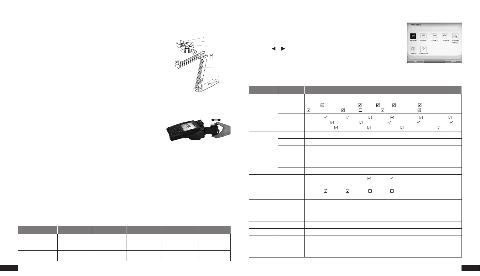
Electrode Stand
Electrode Arm
e
The electrode stand can be attached to either side of the meter and up to two stands can be attached to each meter. A
weighted base (Catalog Number STARA-HB) is also available to support the stand without a meter.
1. Open the box containing the electrode stand. The box will include a base plate,
electrode arm, pivot pin, electrode holder, ATC spacer and RDO clip.
2. Turn the meter over, with the meter display facing down, on a clean dry surface.
3. Identify the side of the meter that the stand will be installed on and remove the
RDO Clip
ATC spacer
Electrode Head
Pivot pin
screw between the circles on that side of the meter.
4. Align the base plate of the stand with the circles on the meter.
5. Replace the screw from step 3 to attach the base plate to the meter.
6. Turn the meter over, with the meter display facing up.
Base Plat
7. Insert the electrode arm into the metal post on the base plate.
8. Connect the electrode holder to the electrode arm using the pivot pin.
Meter and Module System
Versa star meters and modules can be purchased individually or as preconfigured systems with up to four modules
already connected with the channels. Modules are labeled for easy identification.
1. pH, pH/ISE, Conductivity and RDO/Dissolved Oxygen modules – each connects with one channel.
2. pH/LogR module connects with two channels.
3. Unused channels are covered with blank modules.
4. Modules can be moved among the four available channels as needed,
regardless of whether the meter is powered on or off.
Module Insertion
1. Hold the top (labeled) and bottom tabs on the module with your thumb and index finger and squeeze the tabs
towards each other.
2. Slide the module straight into an open channel grove on the back of the meter. The tabs should snap into place when
the module is fully connected to the meter.
3. Release the top and bottom tabs on the module.
4. The meter will update the channel ID display with the module ID in the corresponding channel location.
Module Removal
1. Hold the top (labeled) and bottom tabs on the module with your thumb and index finger and squeeze the tabs
towards each other.
2. Pull straight back to remove the module from channel grove on the back of the meter.
3. The meter will update the channel ID display with dashes in the previous channel location.
Module Measurement Capabilities
Module Catalog No. VSTAR-PH VSTAR-ISE VSTAR-LR VSTAR-CND VSTAR-RD
Label pH pH/ISE pH/LogR Cond RDO/DO
Measurement Modes pH, mV, RmV, ORP
Temperature Modes Automatic, Manual Automatic, Manual
2 | Versa star Meter
pH, mV, RmV,
ORP, ISE
pH, mV, RmV, ORP
Automatic,
Manual, LogR
Conductivity, TDS,
Salinity, Resistivity
Automatic, Manual Automatic
% Saturation,
mg/L
Meter Setup Menus
The Main Setup menu contains up to four channel-specific measurement menus,
instrument settings menu, calibration and data log view menu, and meter diagnostics
menu in one easy to access location.
1. In the measurement mode, press the setup key.
2. Press the or key to highlight the appropriate setup menu and press the
f3 (Select) key.
3. View and update the displayed menu options.
Instrument Settings Setup Menu
Use the Instrument Settings setup menu to update meter settings for the display, sound, date and time, language, data
transfer, stirrer speed and channel assignment, screen saver and auto-shutoff feature.
Main Menu Submenu Settings
Brightness Level 1, Level 2, Level 3, Level 4, Level 5
Display
Communication
Buzzer
Stirrer
Calendar
Language English, Spanish, German, Italian, French, Chinese, Portuguese
Data Log Off, On
Printing Off, On
Print Format CSV, Printer
Screen Saver Off, On
Auto Shut Off Off, On
Display View
Display
Format
USB
RS232 1200, 2400, 4800, 9600, 19200, 38400, 57600, 115200
USB PRINTER
Key Press Off, On
Ready Off, On
Alarm Off, O n
Stirrer 1
Stirrer 2
Time 12, 24 Hrs
Date DD-MM-YY, MM-DD-YY, DD-MMM-YY
Channel , Measurement Mode , Method , Stable , Temperature , Secondary Parameter
, Calibration Details , User ID , Sample ID , Electrode Serial No.
Channel 1 , Channel 2 , Channel 3 , Channel 4 , Channel 1 & 2 , Channel 1 & 3 ,
Channel 1 & 4 , Channel 2 & 3 , Channel 2 & 4 , Channel 3 & 4 , Channel 1, 2 & 3 ,
Channel 1, 2 & 4 , Channel 1, 3 & 4 , Channel 2, 3 & 4 , Channel 1, 2, 3 & 4
Channel 1 , Channel 2 , Channel 3 , Channel 4
Speed 1, 2, 3, 4, 5
Channel 1 , Channel 2 , Channel 3 , Channel 4
Speed 1, 2, 3, 4, 5
Versa star Meter | 3
 Loading...