

Page 1

Thermo Scientific
Orion 2111XP
Sodium Analyzer
UM-263639-005 • Revision B • January 2017
Page 2

Contents
Section 1 General Information. . . . . . . . . . . . . . . . . . . . . . . . . . . . . . . . . . . . 1
Introduction . . . . . . . . . . . . . . . . . . . . . . . . . . . . . . . . . . . . . . . . . . . . . . . . . . . . . . . . . 1
Features and Benefits . . . . . . . . . . . . . . . . . . . . . . . . . . . . . . . . . . . . . . . . . . . . . . . . 2
Application Packages . . . . . . . . . . . . . . . . . . . . . . . . . . . . . . . . . . . . . . . . . . . . . . . . . 3
Principles of Operation . . . . . . . . . . . . . . . . . . . . . . . . . . . . . . . . . . . . . . . . . . . . . . . . 4
Principles of Calibration . . . . . . . . . . . . . . . . . . . . . . . . . . . . . . . . . . . . . . . . . . . . . . . 5
Double Known Addition (DKA). . . . . . . . . . . . . . . . . . . . . . . . . . . . . . . . . . . . . . . 5
Offline Calibration. . . . . . . . . . . . . . . . . . . . . . . . . . . . . . . . . . . . . . . . . . . . . . . . . 7
Fluidics Diagram . . . . . . . . . . . . . . . . . . . . . . . . . . . . . . . . . . . . . . . . . . . . . . . . . . . . . 7
Glossary . . . . . . . . . . . . . . . . . . . . . . . . . . . . . . . . . . . . . . . . . . . . . . . . . . . . . . . . . . . 8
Two Channel Analyzer Configurations . . . . . . . . . . . . . . . . . . . . . . . . . . . . . . . . . . . . 9
Section 2 Analyzer Preparation. . . . . . . . . . . . . . . . . . . . . . . . . . . . . . . . . . 10
Unpacking the Analyzer . . . . . . . . . . . . . . . . . . . . . . . . . . . . . . . . . . . . . . . . . . . . . . 10
Mounting and Plumbing Instructions . . . . . . . . . . . . . . . . . . . . . . . . . . . . . . . . . . . . 11
Sample Requirements . . . . . . . . . . . . . . . . . . . . . . . . . . . . . . . . . . . . . . . . . . . . . . . 12
Electrical Wiring . . . . . . . . . . . . . . . . . . . . . . . . . . . . . . . . . . . . . . . . . . . . . . . . . . . . 12
Safety Requirements . . . . . . . . . . . . . . . . . . . . . . . . . . . . . . . . . . . . . . . . . . . . . 12
Warning Labels and Locations. . . . . . . . . . . . . . . . . . . . . . . . . . . . . . . . . . . . . . 13
Wiring the Analyzer . . . . . . . . . . . . . . . . . . . . . . . . . . . . . . . . . . . . . . . . . . . . . . . . . 14
Terminal Assignments . . . . . . . . . . . . . . . . . . . . . . . . . . . . . . . . . . . . . . . . . . . . . . . 15
Electrode Wiring Assignments. . . . . . . . . . . . . . . . . . . . . . . . . . . . . . . . . . . . . . 16
Installation of DIPA Reagent and Diffusion Tubing . . . . . . . . . . . . . . . . . . . . . . . . . 17
Installation of Ammonia Reagent and Diffusion Tubing . . . . . . . . . . . . . . . . . . . . . . 20
Installation of New Electrode Cables . . . . . . . . . . . . . . . . . . . . . . . . . . . . . . . . . . . . 21
Installation of the ATC Probe . . . . . . . . . . . . . . . . . . . . . . . . . . . . . . . . . . . . . . . . . . 22
Installation of a New Reference Electrode . . . . . . . . . . . . . . . . . . . . . . . . . . . . . . . . 22
Section 3 Analyzer Operation . . . . . . . . . . . . . . . . . . . . . . . . . . . . . . . . . . .24
Description of Basic Controls . . . . . . . . . . . . . . . . . . . . . . . . . . . . . . . . . . . . . . . . . . 24
Description of Keypad Icons . . . . . . . . . . . . . . . . . . . . . . . . . . . . . . . . . . . . . . . . . . . 25
Use of the Setup Mode . . . . . . . . . . . . . . . . . . . . . . . . . . . . . . . . . . . . . . . . . . . . . . . 26
Setup Mode Overview . . . . . . . . . . . . . . . . . . . . . . . . . . . . . . . . . . . . . . . . . . . . . . . 28
Shutdown and Start-Up Procedure . . . . . . . . . . . . . . . . . . . . . . . . . . . . . . . . . . . . . 53
Section 4 Calibration . . . . . . . . . . . . . . . . . . . . . . . . . . . . . . . . . . . . . . . . . .55
Calibration Setup . . . . . . . . . . . . . . . . . . . . . . . . . . . . . . . . . . . . . . . . . . . . . . . . . . . 55
Flow Cell Operation . . . . . . . . . . . . . . . . . . . . . . . . . . . . . . . . . . . . . . . . . . . . . . . . . 56
Rinsing the Flow Cell . . . . . . . . . . . . . . . . . . . . . . . . . . . . . . . . . . . . . . . . . . . . . . . . 57
Air Regulation . . . . . . . . . . . . . . . . . . . . . . . . . . . . . . . . . . . . . . . . . . . . . . . . . . . . . . 58
Before Performing a DKA Calibration . . . . . . . . . . . . . . . . . . . . . . . . . . . . . . . . . . . . 58
Performing a DKA Calibration . . . . . . . . . . . . . . . . . . . . . . . . . . . . . . . . . . . . . . . . . 60
Page 3

Calibration Abort Steps . . . . . . . . . . . . . . . . . . . . . . . . . . . . . . . . . . . . . . . . . . . . . . .62
Calibration Error Codes . . . . . . . . . . . . . . . . . . . . . . . . . . . . . . . . . . . . . . . . . . . . . . .63
Calibration At Custom Concentrations Using DKA . . . . . . . . . . . . . . . . . . . . . . . . . .64
Span Check Procedure . . . . . . . . . . . . . . . . . . . . . . . . . . . . . . . . . . . . . . . . . . . . . . .65
Offline Calibration Procedure . . . . . . . . . . . . . . . . . . . . . . . . . . . . . . . . . . . . . . . . . . .65
Section 5 Analyzer Maintenance . . . . . . . . . . . . . . . . . . . . . . . . . . . . . . . . 67
Maintenance Schedule . . . . . . . . . . . . . . . . . . . . . . . . . . . . . . . . . . . . . . . . . . . . . . .67
Weekly Maintenance . . . . . . . . . . . . . . . . . . . . . . . . . . . . . . . . . . . . . . . . . . . . . . . . .67
Monthly Maintenance . . . . . . . . . . . . . . . . . . . . . . . . . . . . . . . . . . . . . . . . . . . . . . . . .68
Yearly Preventive Maintenance . . . . . . . . . . . . . . . . . . . . . . . . . . . . . . . . . . . . . . . . .72
Section 6 Troubleshooting . . . . . . . . . . . . . . . . . . . . . . . . . . . . . . . . . . . . . 75
Diagnostics Mode . . . . . . . . . . . . . . . . . . . . . . . . . . . . . . . . . . . . . . . . . . . . . . . . . . .75
Slope Problems . . . . . . . . . . . . . . . . . . . . . . . . . . . . . . . . . . . . . . . . . . . . . . . . . . . . .80
Troubleshooting Matrix . . . . . . . . . . . . . . . . . . . . . . . . . . . . . . . . . . . . . . . . . . . . . . .82
Error/Event Codes . . . . . . . . . . . . . . . . . . . . . . . . . . . . . . . . . . . . . . . . . . . . . . . . . . .83
Resetting the Analyzer . . . . . . . . . . . . . . . . . . . . . . . . . . . . . . . . . . . . . . . . . . . . . . . .86
Serial Number and Software Revision . . . . . . . . . . . . . . . . . . . . . . . . . . . . . . . . . . . .87
Service and Repair . . . . . . . . . . . . . . . . . . . . . . . . . . . . . . . . . . . . . . . . . . . . . . . . . .87
Section 7 Customer Service . . . . . . . . . . . . . . . . . . . . . . . . . . . . . . . . . . . . 90
Notice of Compliance . . . . . . . . . . . . . . . . . . . . . . . . . . . . . . . . . . . . . . . . . . . . . . . . .90
Statement of Conformity . . . . . . . . . . . . . . . . . . . . . . . . . . . . . . . . . . . . . . . . . . . . . .91
WEEE Compliance . . . . . . . . . . . . . . . . . . . . . . . . . . . . . . . . . . . . . . . . . . . . . . . . . .92
Terms and Conditions . . . . . . . . . . . . . . . . . . . . . . . . . . . . . . . . . . . . . . . . . . . . . . . .92
Appendix . . . . . . . . . . . . . . . . . . . . . . . . . . . . . . . . . . . . . . . . . . . . . . . . . . . . . . . . . .95
Mounting Dimensions . . . . . . . . . . . . . . . . . . . . . . . . . . . . . . . . . . . . . . . . . . . . . . . .95
ISE Default Values . . . . . . . . . . . . . . . . . . . . . . . . . . . . . . . . . . . . . . . . . . . . . . . . . . .96
Specifications . . . . . . . . . . . . . . . . . . . . . . . . . . . . . . . . . . . . . . . . . . . . . . . . . . . . . . .96
Ordering Information . . . . . . . . . . . . . . . . . . . . . . . . . . . . . . . . . . . . . . . . . . . . . . . .100
Accessory Options . . . . . . . . . . . . . . . . . . . . . . . . . . . . . . . . . . . . . . . . . . . . . . . . . . 1 02
Field Replaceable Parts . . . . . . . . . . . . . . . . . . . . . . . . . . . . . . . . . . . . . . . . . . . . . .102
Recommended Consumables for Annual Operation . . . . . . . . . . . . . . . . . . . . . . . .103
Pipet Operation . . . . . . . . . . . . . . . . . . . . . . . . . . . . . . . . . . . . . . . . . . . . . . . . . . . .104
Pipet Techniques . . . . . . . . . . . . . . . . . . . . . . . . . . . . . . . . . . . . . . . . . . . . . . . . . . .105
Page 4

S E C T I O N
1 General Information
This user guide covers the operation, maintenance and troubleshooting for the Thermo
Scientific Orion 2111XP sodium analyzer, which offers unmatched reliability in monitoring
critical sample streams throughout the power/steam generation and industrial water industry.
Introduction
Monitoring the sodium ion content of steam and water circuits to produce accurate and
reproducible results requires a very well designed and maintained system. The system must
optimize the fluidic design with the sensing technology to enable low level (ppb) measurement
of the contaminants as well as measuring across the linear ran ge of the analyzer.
The 2111XP sodium analyzer meets all of the criteria for accurate and dependable sodium
monitoring and more. The 2111XP analyzer incorporates inno vative technologies that include:
Premium electrodes
Accurate and precise flow cell design
Marquee help screen
Pump-less reagent addition and DKA calibration system
Thermo Scientific Orion 2111XP Sodium Analyzer | 1
Page 5

1 | General Information
Section
Thermo Scientific Orion 2111XP Sodium Analyzer
Markets
Power
Semiconductor
Chemical and petrochemical
Pulp and paper
Applications
Feedwater / make-up water
Boiler feedwater
Drum boilers
Demineralized water
Steam condensate
Cation exchange breakthrough
High acid samples
Features and Benefits
The Thermo Scientific Orion 2111XP sodium analyzer features an expandable platform design
that incorporates over 30 years of expertise in sodium measurements combined with innovative
Thermo Scientific Orion technologies for superior performance.
Choice of application/reagent packages:
Flexible configurations for applications ranging from low-level detectio n to high acid
samples.
Accurate and precise measurements in the range of 0.30 ppb to 200 ppm:
Reliable measurements and a wide measurement range with selectable resolution.
Premium reference and sensing electrodes:
Superior accuracy and stability over a wide temperature rang e.
Advanced flow cell design with air stirring:
Automatic sample handling and contamination control with no moving parts.
Patented scrolling marquee:
Intuitive menu-driven, digital user interface.
Data log of previous measurements and calibration:
View measurement, calibration and error history.
Self diagnostics:
Ease of maintainability.
Password protection:
Security and peace of mind for your operation.
Auto-ranging electronics with an easy to read backlit LCD display:
Analyzer determines the best range.
| Orion 21 11XP Sodium Analyzer Thermo Scientific
2
Page 6
1 | General Information
Section
Application Packages
The Thermo Scientific Orion 2111XP sodium analyzer is ideally suited to meet the demanding
needs of high purity water measurements and high acid-cation exchange applications, all in one
system and all from one of the most trusted names in sodium monitoring.
The 2111XP analyzer is offered in three application packages that are uniquely designed to
accommodate the changing requirements for successful sodium monitoring. Our flexible reage nt
kits are available in prepackaged bottles for safe and convenient replacement – save your
valuable time and money!
Ammonia Application Package – for general purpose sodium measurements, provides up
to 60 days of continuous operation.
Diisopropylamine (DIPA) Application Package – for low range sodium detection,
provides up to 60 days of continuous operation.
Cation/High Acid Application Package – for cation exchange breakthrough and high acid
samples, provides up to 45 days of continuous operation.
Application Packages
Ammonia Application Package
(Cat. No. 2111XA)
DIPA Application Package
(Cat. No. 2111XD)
Cation / High Acid Application Package
(Cat. No. 2111XC)
Reagent: Ammonia
Range: 0.30 ppb to 200 ppm
Accuracy: ± 5% or 0.3 ppb (with DKA calibration)
Reagent:
Diisopropylamine (DIPA)
Range: 0.10 ppb to 10 ppm
Accuracy: ± 5% or 0.1 ppb (with DKA calibration)
Reagent:
Ammonia
Range: 1.0 ppb to 200 ppm
Accuracy: ± 5% or 2 ppb (with DKA calibration)
Thermo Scientific Orion 2111XP Sodium Analyzer | 3
Page 7
1 | General Information
Section
Safety Drain for
Reagent Overflow
Restrictor Tubing
Pressurizes Flow Cell
Calibration Mode - PUSH
to Initiate Siphoning
Valve Positions
Sample/Measure Mode - PULL
Analyzer
12345
Power
4-20mA Output
Air Pump
FFllooww MMeetteerr
Bypass / Needle
Inlet Valve
Valve and Filter
Regulator
Valve
Reference Solution
Port
Calibration
REF
TEMP
Sense
Flow Cell Block
Calibration Level
Air Filter
Reagent
Reagent Bottle
Diffusion Tube
Fluid Path
Reagent Manifold
Electric
Fluid Restrictor Tubing
Air Path
Reference Solution Path
Diffusion Tubing
KEY
Reagent Overflow Path
Main Feed
Air Inlet
Measure Level
Drain
Check
Valve
Sample
VVVaaaalllvlvveee
Cal
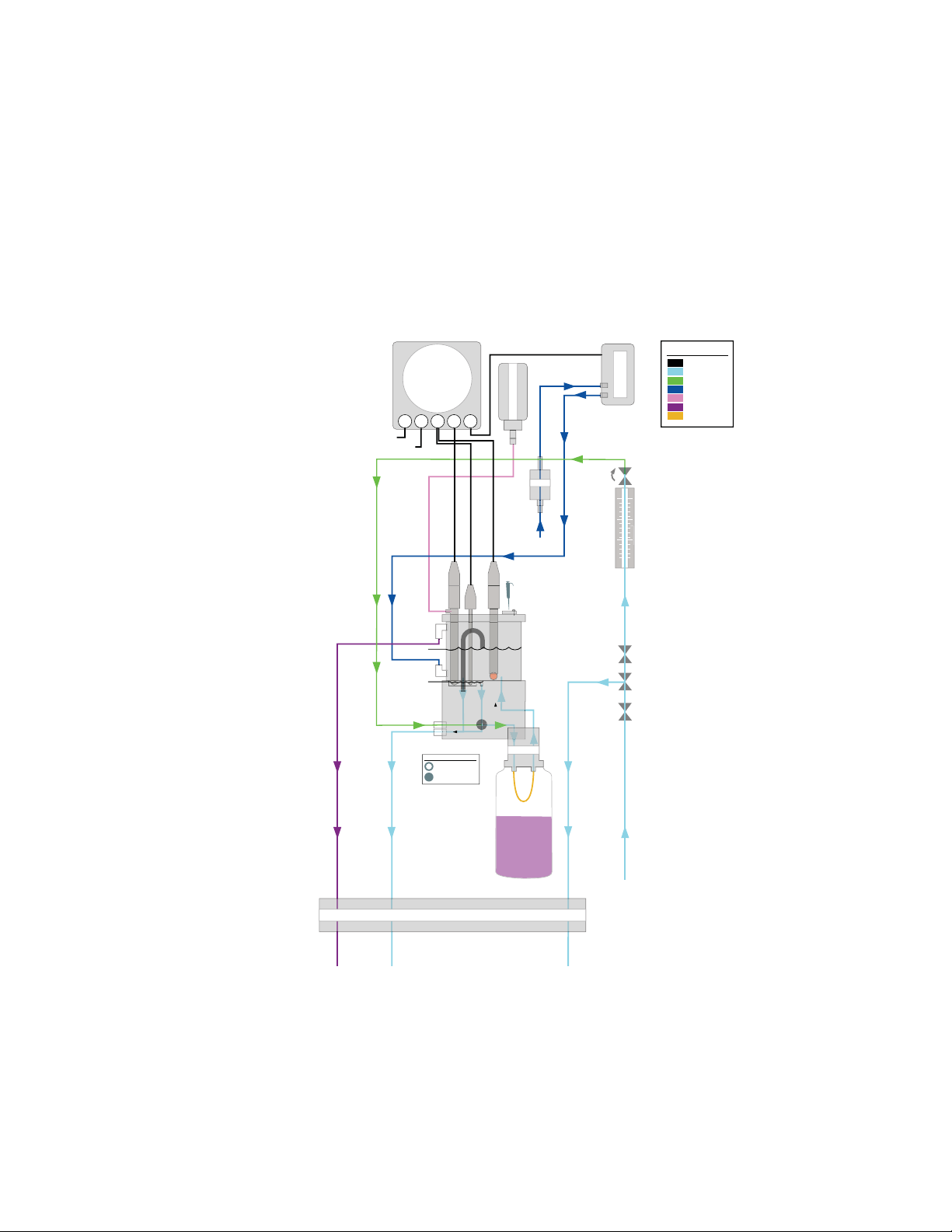
Principles of Operation
The sample enters the Thermo Scientific Orion 2111XP sodium analyzer and passes through
the inlet valve, bypass/needle valve, inlet filter, pressure regulator, flow meter and into the
restrictor tubing. The sample then passes through t he flow cell manifold into a reag ent bottle and
through a diffusion tubing assembly where pH adjustment takes place. The pH-adjusted sample
then flows back through the manifold into the flow cell as air is introd uced from the air pump to
ensure proper mixing and fast response. The sample then flows into an atmospheric drain via
the diverter valve.
Figure 1: 2111XP Schematic
The sensing electrode responds logarithmically to change s in the sodium ion concentratio n. This
response is described by the Nernst equation:
+ 2.3 (RT/nF) log (C/C
E = E
0
Where:
iso
)
E = measured electrode potential, mV
E
| Orion 21 11XP Sodium Analyzer Thermo Scientific
4
= potential, when C equals C
0
iso
, mV
Page 8

1 | General Information
Section
R = ideal gas constant
T = temperature of sample, degrees K
n = valence of ionic species (+1 for sodium ion)
F = Faraday’s constant
C = effective sodium ion concentration (activity)
C
= concentration (activity) of sodium ion where potential E is temperature
iso
independent (isopotential point)
The above equation indicates that the measured potential varies with both temperature and the
concentration of the ion of the interest. In order to eliminate error caused by fluctu ations in
sample temperature, the 2111XP microprocessor constantly updates temperature corrections
from data supplied by the ATC probe.
From the Nernst equation, the theoretical response of a sodium ion selective electrode to a
ten-fold change in concentration at 25 °C is 59.16 mV. This is referred to as the elect rode slop e
(S). Most electrodes, however, do not exhibit a theoretical slope. Therefore, the an alyzer is
calibrated to determine its actual value. Two standards ar e used to provide information
necessary for the microprocessor to compute the actual slope and E
for use during sample
0
analysis.
In order to eliminate interference from hydrogen ions, which can become significant when
measuring low levels of sodium, the 2111XP analyzer raises the samp le pH. This pH adjustment
is accomplished by the patented passive-diffusion process wherei n the sample passes through
a length of tubing contained in the reagent bottle. The reagent diffu ses through the tube wall and
mixes with the sample, which raises the sample pH.
Principles of Calibration
Calibration procedures for analytical instruments are impo rtant and must be performed carefully.
The calibration procedure used in the Thermo Scientific Orion 2111XP analyzer is a variation of
Double Known Addition (DKA) using advan ced electrode and flow cell technology in
combination with the passive diffusion system. This method has the distinct advantages of being
fast, easy, and accurate.
Double Known Addition (DKA)
Before calibration begins, the diverter valve is pushed in to divert flow from the measure drain,
allowing the flow cell to fill.
At the beginning of the DKA calibration the actual concentration in the sample is unknown. The
analyzer measures the potential (E
amount of standard 1 solution is added to the flow cell, which increases the concentration (C
with a corresponding known amount (d
) and stores this value in the microprocessor. A known
s
). During this process, air is pumped into the flow cell,
c1
)
s
Thermo Scientific Orion 2111XP Sodium Analyzer | 5
Page 9
1 | General Information
Section
thoroughly mixing sample and standard in a closed- loop system. The new potential (E1) is
measured and stored automatically when stability is reached. Adding standard 2, preferably 10
times more concentrated than standard 1, increases the concentration (d
reservoir. Again, the new potential (E
) is measured and stored when the reading is stab le. Now,
2
) in the sample
c2
we have the following three unknowns:
E
= E0 + S(Ts/298.15) log (Cs/C
s
E
=E0 + S(T1/298.15) log [(Cs + dC1)/C
1
E
=E0 + S(T2/298.15) log [(Cs+ dC1+ dC2)/C
2
iso
)
]
iso
]
iso
S is the Slope at 25 °C (298.15 K)
T is the temperature in Kelvin, measured when the potential E is measured.
E
, E1, E2 have been determined during the calibration procedure. The microprocessor solves
s
these three equations, to obtain the values of S and E
. The calibration result is stored for use
0
during online monitoring to convert the measured potential and temperature in the sample into
concentration values in either ppm or ppb.
Figure 2: Flow Cell Volume for DKA
When the calibration is complete the flow cell drains as the sample flow returns. The flow cell
volume returns to the measurement level. After allowing approximately 30 minutes for
concentrated calibration solution to be flushed from the system, the 2111XP analyzer can begin
sample measurement again.
In addition to Double Known Addition (DKA), the 2111XP analyzer also allows the operator the
ability to perform an offline calibration.
| Orion 21 11XP Sodium Analyzer Thermo Scientific
6
Page 10
1 | General Information
Section
Offline Calibration
The offline calibration feature of the 2111XP an alyzer a llo ws th e op era tor to adjust the analyzer
to values determined by alternate methods used in their lab oratory such as elemental
spectroscopy and ion chromatography.
The offline calibration is essentially a one point calibration. To perform an offline calibration, a
sample is taken from the bypass of the analyzer; the sample concentration value is stored in
memory; the sample is analyzed by an alternate method of choice; the previously stored reading
is adjusted to the lab method result; and the analyzer is then returned to the analysis mode. The
term “offline calibration” refers only to the fact that a sample from 2111XP analyzer bypass is
taken “offline” for laboratory analysis; in fact, no downtime is experienced during the procedure
and the analyzer remains online throughout.
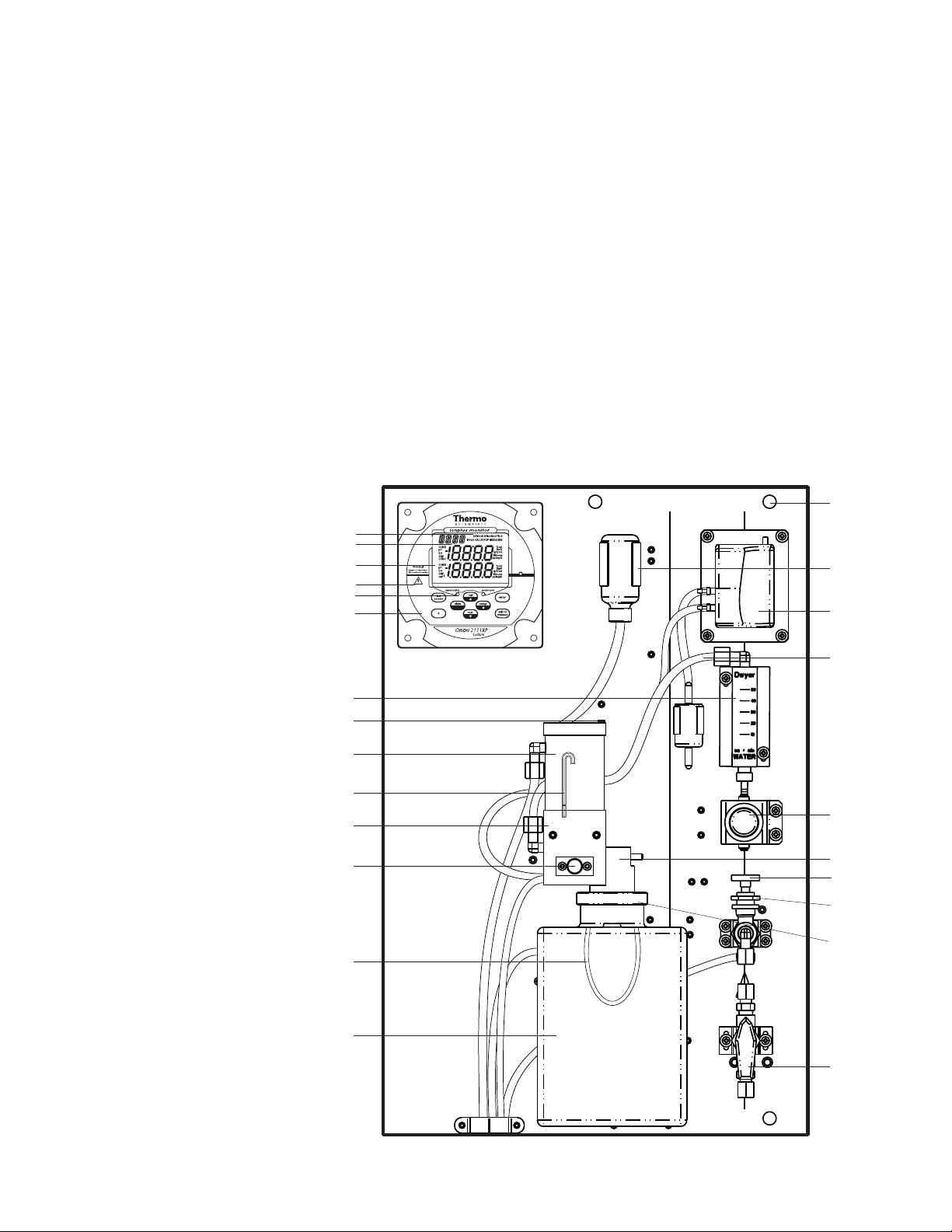
Fluidics Diagram
Figure 3: Fluidics Diagram
Mode Indicator
Scrolling Marquee
LCD Display
Warning Icon
Status Indicators
Keypad
Flow Meter
Calibration Port
Flow Cell
Reservoir
Siphon Tube
Flow Cell Block
Diverter Valve
Diffusion Tubing
Assembly
Mounting
Hole
Reference
Filling
Solution
Air Pump
Restructor
Tube
Assembly
Pressure
Regulator
Reagent
Manifold
Bypass/Needle
Valve
Inlet Filter
Reagent
Bottle
Adapter
Assembly
Reagent Bottle
Inlet Valve
Thermo Scientific Orion 2111XP Sodium Analyzer | 7
Page 11

1 | General Information
Section
Glossary
Refer to Figure 3.
Inlet Valve – Accepts the sample stream via 1/4 inch NPTF connector. The operator must
supply the sample with a pressure between 8 and 100 psig.
Inlet Filter – 60 micron stainless steel filter traps particulate matter in the sample stream.
Bypass/Needle Valve – Used to redirect flow in the bypass system.
Pressure Regulator – Adjusts flow on the incoming sample stream.
Flow Meter – Measures sample flow rate.
Restrictor Tube Assembly – Used in conjunction with the pressure regulator to lower
downstream pressure.
Reagent Manifold – Directs sample flow in and out of the reagent bottle assembly.
Reagent Bottle Adapter Assembly – Connects the reagent bottle assembly to the manifold.
Diffusion Tubing Assembly – Semi-permeable tubing through which reagent diffuses into the
sample.
Reagent Bottle – Contains water-soluble amine or ammonia reagent that raise the sa mple pH.
Flow Cell – Contains sodium sensing electrode, reference electrode and ATC probe.
Diverter Valve – Allows the flow cell reservoir to fill during calibration by forming a closed-loop
system.
Sodium Sensing Electrode – Senses sodium ions in sample stream and produce an e lectrical
potential dependent on sample concentration.
Reference Electrode – Provides a constant reference potential and completes the
measurement circuit.
Reference Electrode Filling Solution Bottle – Provides constant flow of electrolyte solution
through reference electrode for maximum stability.
ATC Probe – Measures sample temperature and inputs data to microprocessor for automatic
temperature compensation (ATC).
| Orion 21 11XP Sodium Analyzer Thermo Scientific
8
Page 12
1 | General Information
Section
Calibration Port – Allows introduction of standards to the sample reservoir during calibration.
LCD Display – Provides digital readouts of concentration, temperature, millivolts and error
codes.
Air Pump – Used to mix the sample during both measurement and calibration.
Keypad – Consists of five mode keys, four prompt indicator lights, two scroll keys and one key
for entering data. Mode and error indicators are also incorporated on the keypad.
Status Indicator – Two LED lights that illuminate according to current status of the analyzer.
Green Light: Indicates that system is in correct working condition.
Yellow Light: Indicates a warning, system in hold or that maintenance is required.
Red Light: Indicates that something is seriously wrong.
Note: When either the yellow or red LED is lit, there may be an entry in the diagnostics mode
that indicates the error. The logging feature must be initiated in the setup mode. Refer to
Section 3, Use of the Setup Mode for instructions.
Two Channel Analyzer Configurations
A pH/ORP module or conductivity module can be added by the operator to the second channel
of the Thermo Scientific Orion 2111XP sodium analyzer for the ultimate flexibility in
measurement capabilities. The 2100 series pH/ORP and conduc tivity an alyzers provide
accurate and reliable measurements in ultra pure water as well as the harshest industrial
environments. Combined with decades of superior Thermo Scientific Orion sensor technology,
our systems provide rapid results with complete stability.
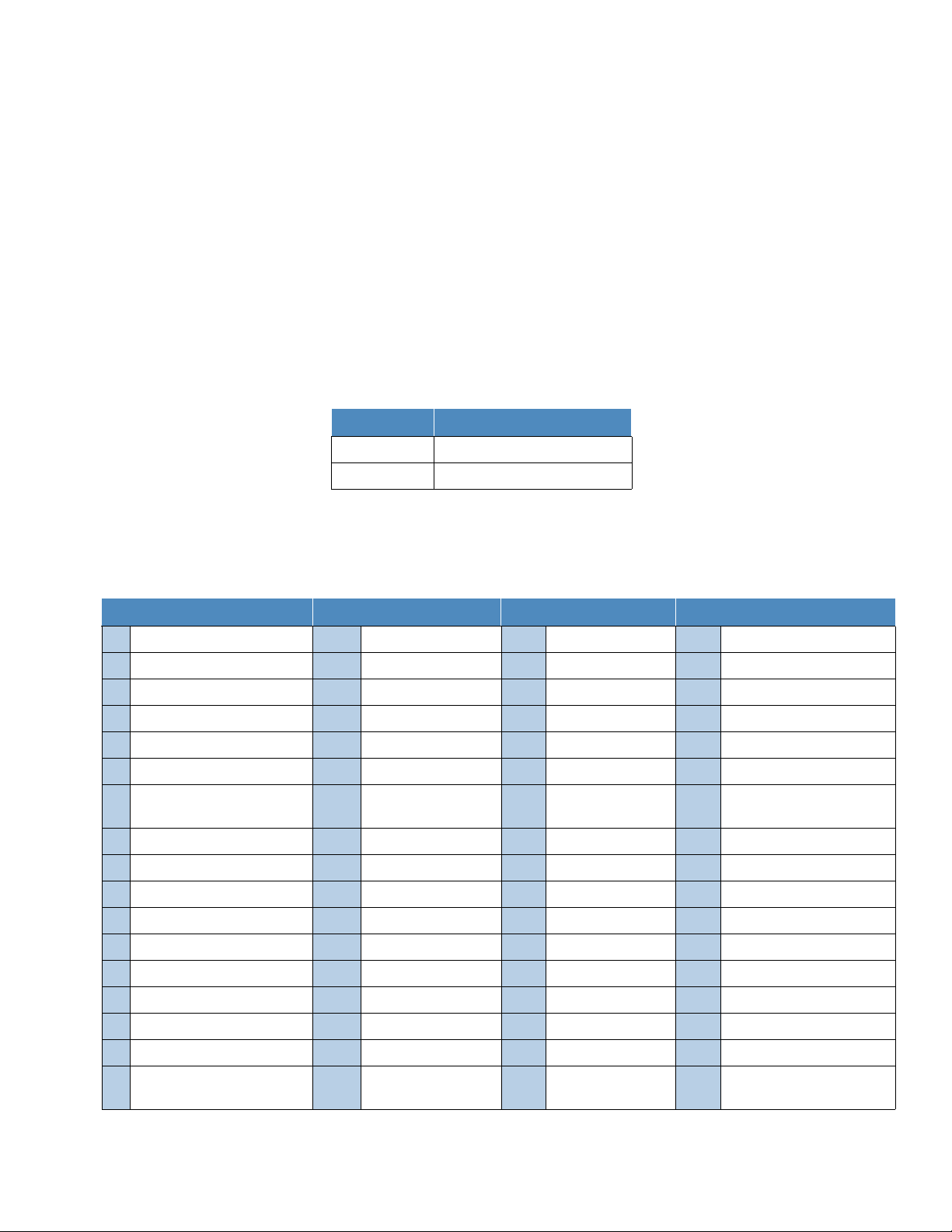
Cat.No Description
2100PH2 Second channel module for pH/ORP
2100CD2 Second channel module for conductivity
When a pH/ORP module or conductivity module is installed on the second channel of the
2111XP sodium analyzer, refer to the Thermo Scientific Orion 2100 Series pH/ORP Analyzer
and Conductivity Analyzer User Guide for detailed instructions on operating the pH/ORP or
conductivity analyzer. Visit www.thermofisher.com/water
analyzer user guides.
to download any of the 2100 series
Thermo Scientific Orion 2111XP Sodium Analyzer | 9
Page 13

S E C T I O N
2 Analyzer Preparation
WARNING: The instructions provided in this user guide are recommendations from the
manufacturer to ensure safe and correct operation of the an alyzer. If the analyzer is not used as
recommended by the manufacturer this can lead to incorrect operation or injury.
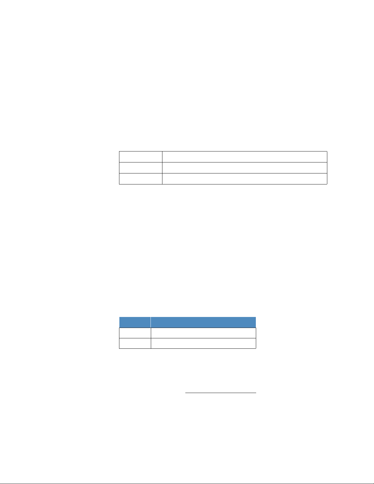
Unpacking the Analyzer
Thermo Scientific Orion analyzers are assembled, tested and packaged with great care. Refer
to Figure 4.
Report any obvious damage of shipping container to carrier and hold for inspection. The carrier
(not Thermo Fisher Scientific) is responsible for any damage incurred during shipment.
1. Open the outer box. Remove the top two foam corner support pieces.
2. Open the inner box. This box should contain the analyzer and ATC temperature probe,
sodium electrode box, reference electrode box, low level standards kit (two 2 oz. bottles of
standard 1, 19.1 ppm sodium; two 2 oz. bottles of standard 2, 192 ppm sodium; and
one 2 oz. bottle of etching solution), high level standards kit (two 2 oz. bottles of standard
1, 1910 ppm sodium; two 2 oz. bottles of standard 2, 19200 ppm sodium; and one 2 oz.
bottle of etching solution), the options kit and user guide CD.
10 | Orion 2111XP Sodium Analyzer Thermo Scientific
3. Remove the cardboard retaining shell by sliding it over the entire mounting board and the
analyzer.
4. Carefully remove the entire mounting board with analyzer from the inner box.
Note: Do not lift or pull the analyzer by the fluidics or the electronic components. Use the
back panel to lift the analyzer system.
Page 14
Section
Figure 4: Unpacking the Analyzer
2 | Analyzer Preparation
5. Unbolt the analyzer from the mounting board by removing the four mounting bolts with a
9/16'' wrench. These bolts may be discarded.
6. Carefully place the analyzer at a convenient location until proper installation can be
completed.
Mounting and Plumbing Instructions
Refer to the Appendix, Mounting Dimensions section.
WARNING: Do not connect power prior to the mounting and plumbing of the analyzer.
Recommendations
Select a site for the analyzer that allows it to be permanently bolted with ample height for
atmospheric drain operation. Be sure that there is ready access to the e lectronic controls,
calibration port and electrodes.
A clearance of 15 inch (about 40 cm) must be allowed above the flow cell calibration port.
Insert the pipet vertically (not angled) during the calibration.
The analyzer location must permit connections to a sample line, drain and AC power supply
and any connections for output devices.
The analyzer should be mounted as close to the sampling point as possible. This ensures
the fastest possible response to a changing sample condition. Refer to the Appendix,
Sample Conditions section.
For proper flow cell operation, the analyzer must be installed straight and level upon its
mounting location. Failure to level the analyzer may cause poor siphoning in the flow cell.
Thermo Scientific Orion 2111XP Sodium Analyzer | 11
Page 15

2 | Analyzer Preparation
Section
Instructions
1. Prepare the mounting holes. Carefully lift the analyzer and bolt it into place. Do not lift the
analyzer by holding on to any of the plumbing or fluid handling components.
2. Connect a waste line to the outlet of the an alyzer, which is 3⁄4'' NPT male. The waste line
should be connected to a drain of sufficient capacity, 0.5 inch (1.27 cm) OD is
recommended.
3. Connect a sample line to the inlet of the analyzer, which is 1⁄4'' NPT female. It is
recommended that a shutoff valve be installed at the sampling point.
4. The analyzer must be mounted and leveled vertically for proper operation.
Sample Requirements
Additional information is listed in the Appendix, Specifications section.
Sample inlet connection – 1/4'' NPTF. If particulate matter is present in the sample,
pre-filtration is necessary. The 60 micron stainless steel filter located after inlet valve will remove
moderate amounts of particulates.
Flow rate – 40 mL/minute (nominal) for the Ammonia and DIPA Application Packages and 25
mL/minute (nominal) for the Cation/High Acid Application Package.
Pressure – 8 to 100 psig. Consult Technical Support for details on sample ha ndling if the
pressure is outside of this range.
Temperature – Temperature must be between 5 and 45°C.
Sodium level – Sodium levels are read directly in ppb or ppm, when calibrated with Thermo
Scientific Orion sodium standards 1 and 2.
Sample alkalinity – Sample alkalinity should be less than 250 ppm CaCO
equivalent. For
3
higher sample alkalinity, contact Technical Support.
Electrical Wiring
The warning icon highlights important information that should be strictly follow ed when using the
analyzer for your own safety. Failure to follow these instructions may res ult in injuries.
WARNING: Read and observe the following safety recommendations.
Safety Requirements
Prior to wiring, a switch or circuit breaker for disconnecting the analyzer from power supply
should be installed.
The switch should be in close proximity to the analyzer and with easy reach o f the user.
The switch should be marked as the disconnecting device for the analyzer.
| Orion 2111XP Sodium Analyzer Thermo Scientific
12
Page 16
2 | Analyzer Preparation
Section
Ch 1 status
Ch 2 status
t Ch 1
t Ch 2
To reduce the risk of shock hazard, disconnect the power prior to opening the analyzer.
Before connecting the analyzer to the main, make sure that the voltage lies within either
range: 100-120V 200mA / 200-240V 100mA; 50-60 Hz AC.
Cutting off the power by disconnecting power source will not reset the analyzer. This
analyzer incorporates a non-volatile memory and will maintain calibration an d setting s after
power failure. Battery power is supplied to the display for the date and time functions.
If a repair is required, or to arrange Return Material Authorization, call Technical Sup port or
contact your local authorized dealer.
Installation and wiring of the analyzer may only be carried out in accordance wit h applicable
local and national codes per this user guide.
Be sure to observe the technical specifications and input ratings.
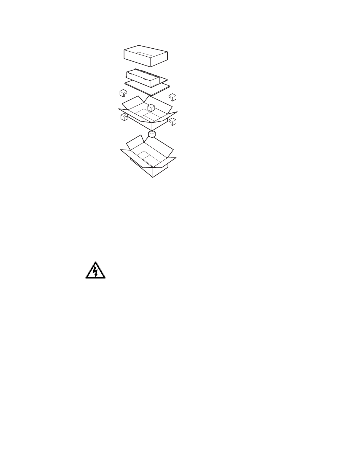
Warning Labels and Locations
WARNING: The following section provides important information that should be strictly follo wed
when using the analyzer for your own safety. Failure to fo llow these instructions may result in
injuries.
Figure 5: Faceplate
Figure 6: Power Supply
The safety warning icons are used in two locations on the analyzer.
Faceplate – Refer to Figure 5.
Power supply – Refer to Figure 6.
.
Note: Replace the fuse only with a fuse of same rating.
Thermo Scientific Orion 2111XP Sodium Analyzer | 13
Page 17
2 | Analyzer Preparation
Section
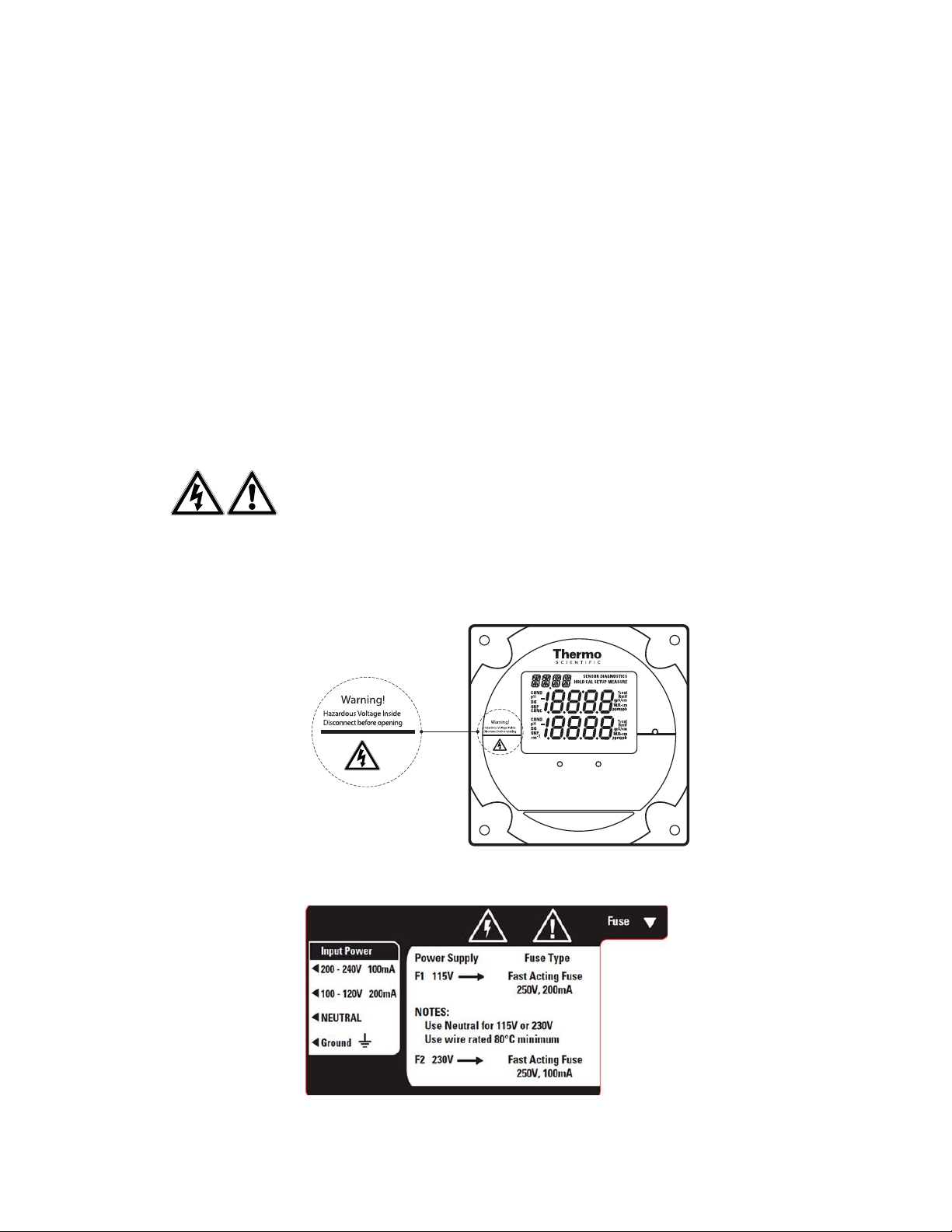
Wiring the Analyzer
WARNING: Read and observe the following requirements. If you install the wro ng fuse for your
system, you could damage the analyzer. Make sure that you select the correct fuse rating and
discard the additional fuses supplied in the fuse kit.
Required Tools
Options kit – includes fuses, cable glands, conduit fitting and gre en screw terminal.
Phillips head screwdriver.
2 mm blade flat-head screwdriver.
Figure 7: Electronic Enclosure with Cable
Glands
1. Open the faceplate – loosen the four screws using a Phillips head screwdriver. The
electronics faceplate will open via the hi nge pin connection.
2. Remove one or two of the two unused ca ble glands as required for wiring power cable or
auxiliary connections. Power cable optional hole locations are shown in Figure 7.
3. Select and install the appropriate size cable gland or conduit fitting as required.
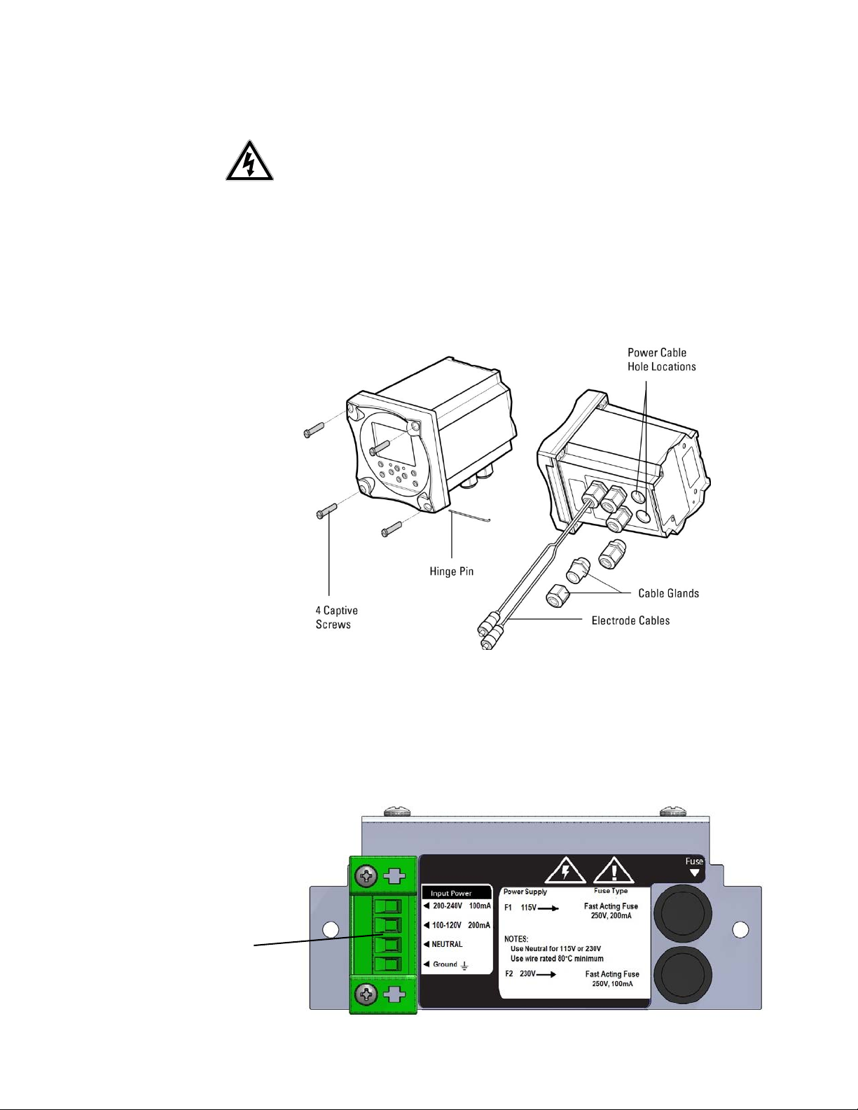
Figure 8: Terminal Connector Location
Terminal Connector
| Orion 2111XP Sodium Analyzer Thermo Scientific
14
Page 18
2 | Analyzer Preparation
Section
4. Feed the power cable throu gh the conduit or cable glands as required.
5. Wire the power cable to the green screw terminal connector from the options kit. Select
correct terminal for hot conductor depending on line voltage, insert ground wire into the
correct terminal and connect the other cable to the neutral terminal. Refer to Figure 8 for
terminal connector location.
6. Plug the terminal connector into the power supply. Refer to Figure 6.
7. The universal power supply uses both fuses in the fuse kit. Install by inserting the fuse in the
fuse holder and secure it using the twist and lock method. The fuses are clearly labeled with
the appropriate voltages for your system. Refer to Figure 6 and Figure 8 for the correct fuse
holder positions. Refer to the table below for fuses required.
AC Voltage Fuse rating
115V 200mA, 250V, Fast Acting
230V 100mA, 250V Fast Acting
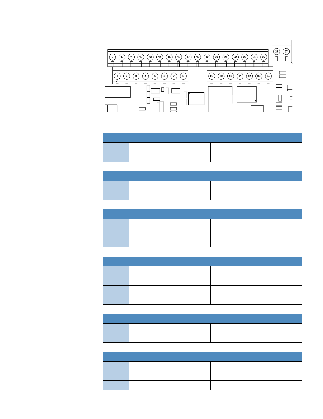
Terminal Assignments
Terminal Layout Terminal Layout Terminal Layout Terminal Layout
1 mA1 output 9 Relay 1 26 Sensing electrode 28 Do not connect
2 GND common ground 10 Relay 1 27 Do not connect 29 Do not connect
3 mA2 output 11 Relay 2 30 Preamp power
4 Air pump (ISE only) 12 Relay 2 31 Preamp ground
5 Air pump (ISE only) 13 Relay 3 32 Shield
6 Shield ground for conductivity 14 Relay 3 33 Shield
7 Do not connect 15 Do not connect 34 Jumper to pin 26 when
using preamp
8 Do not connect 16 Temperature ground
17 Temperature drive
18 Temperature sense
19 Solution ground
20 Conductivity drive +
21 Conductivity sense +
22 Conductivity sense -
23 Conductivity drive -
24 Reference electrode
25 Jumper to pin 24
when using preamp
Thermo Scientific Orion 2111XP Sodium Analyzer | 15
Page 19
2 | Analyzer Preparation
Section
Figure 9: Terminal Assignments
Electrode Wiring Assignments
Sodium Electrode
26
33
Sensing Electrode Connect clear wire
Shield Connect black wire
Reference Electrode
24
32
Reference electrode Connect clear wire
Shield Connect black wire
2100TP Temperature Probe
16
17
19
Temperature ground /thermistor Connect white wire
Temperature drive /thermistor Connect green wire
Solution ground Connect red wire
2001TM Temperature Probe
16
17
18
19
Temperature ground /thermistor Connect white wire
Temperature drive /thermistor Connect green wire, jumper 17 and 18
Temperature sense Jumper to 17
Solution ground Connect red wire
2001SC pH Electrode
24
26
Reference electrode Connect black wire
Sensing electrode Connect clear wire
110250 ORP Electrode
19
24
26
| Orion 2111XP Sodium Analyzer Thermo Scientific
16
Solution ground Connect black wire
Reference electrode Connect purple wire
Sensing electrode Connect coax center wire
Page 20
Section
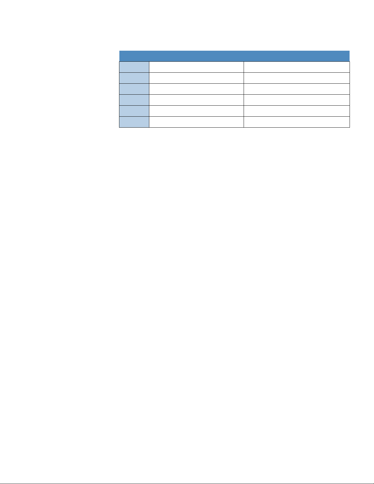
2002CC and 2002SS Conductivity Probes
2 | Analyzer Preparation
6
16
17
20
21
22
Shield ground for conductivity Connect clear wire
Temperature ground /thermistor Connect white wire
Temperature drive /thermistor Connect black wire
Conductivity drive + Connect orange wire
Conductivity sense + Connect red wire
Conductivity sense - Connect green wire
Note: Only reference the wiring configurations that are applicable to your analyzer and
electrodes.
Installation of DIPA Reagent and Diffusion
Tubing
WARNING: The diisopropylamine (DIPA) reagent is hazardous. Use pro tective glasses and
gloves. Refer to the bottle label for precautions and work in a well-ventilated area. Installation of
DIPA reagent requires a fume hood or well-ventilated area.
Recommendations
If the analyzer is offline or the sample flow is shut off from t he analyzer fo r a prolonge d period of
time, follow the steps in Section 3, Shutdown and Start-Up Procedure.
1. Unscrew the thumb nut and remove the reagent bottle from the reagent manifold.
New analyzers will ship with a rubber coated glass reagent bottle and compl ete diffusion
tubing assembly installed. Only installation of the reagent is necessary for first time
start-up.
2. Twist open the reagent bottle, separating the glass bottle, reagent bottle adapter assembly
and plastic cap to the reagent bottle.
DIPA Diffusion Tubing Assembly
Designed to maximize uptime, our new diffusion tubing assembly can be replaced in a matter of
seconds. Our method of snap and connect tubing installation combined with the easy pull off
and dispose technique will have your system back online faster than ever before. The newly
designed mechanism is precisely engineered to remain conn ected under variable temperature
conditions and pressure fluctuations. The new style diffusion tubing assemb ly is now suspended
in the headspace of the reagent bottle, which decreases the rate o f consumption of reagent and
saves you time and money.
The diffusion tubing ships fully assembled for quick and easy installation.
Do not use Teflon tape during installation.
Twisting of the clear silicone tubing will compromise tubing integrity and may cause
ruptures. Be careful to avoid kinks and twisting during installation.
Thermo Scientific Orion 2111XP Sodium Analyzer | 17
Page 21
2 | Analyzer Preparation
Section
Note: The diffusion tube assembly mounts directly to the reagent bottle adapter fittings
(2100RF). The reagent bottle adapter fittings are dedicated t o the reagent bottle adapter an d do
not require change out when installing new diffusion tubing. Be sure to hand tighten these
connectors monthly.
Diffusion Tubing Installation
Note: Turn off the air pump before beginning this procedure; otherwise, the air pump will splatter
the reagent outward as the bottle is removed.
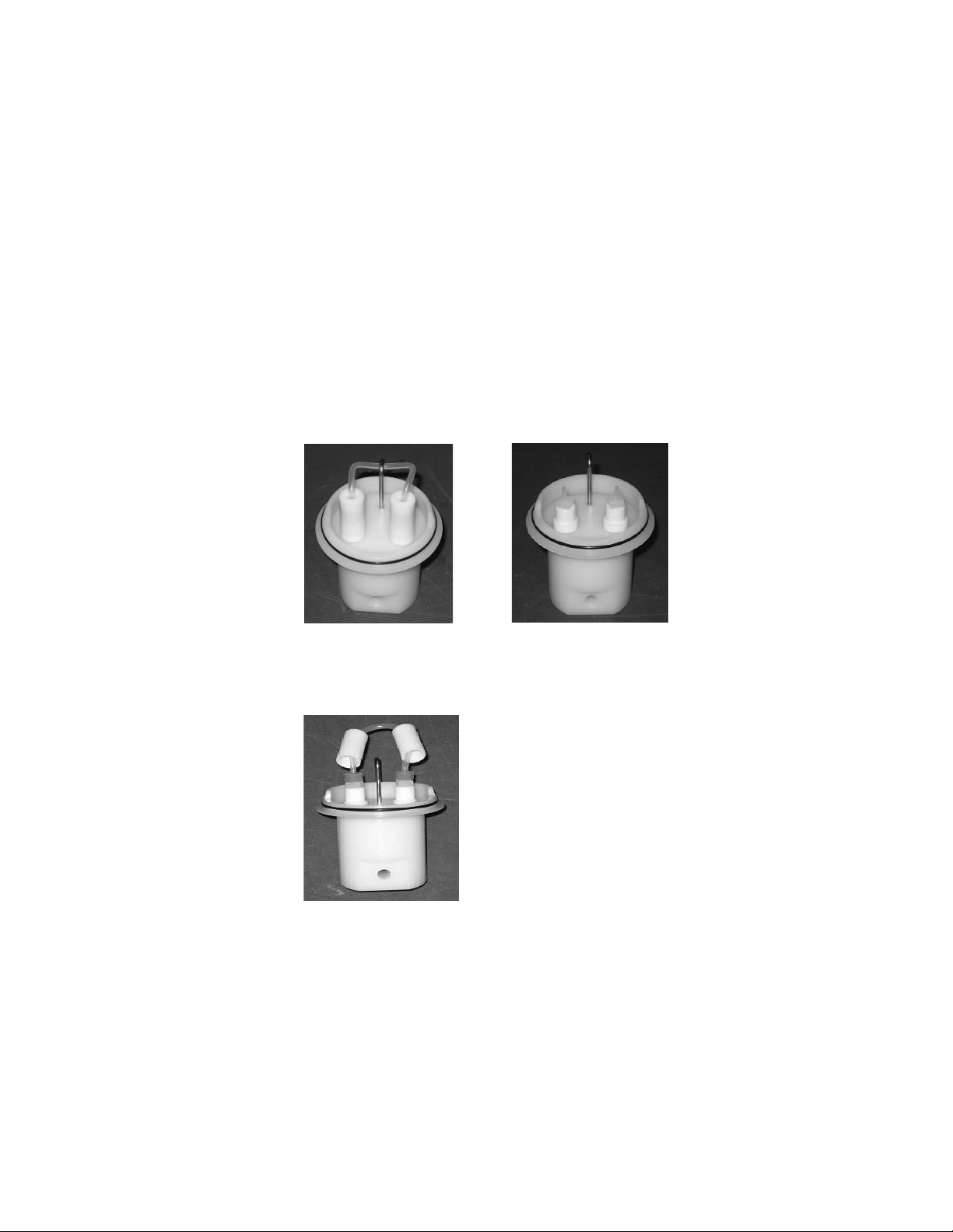
1. Remove the diffusion tubing assembly by unhooking the tubing from the hook, pulling off the
two diffusion tubing caps and pulling the tubing off of the connectors, as shown in
Figure 10.
Note: Ensure the connectors are finger tight to prevent possible leakage of sample into the
reagent.
Figure 10 : Diffusion Tubing Assembly
Figure 11
2. Check the new tubing assembly to make sure no black O-rings are caught in the caps.
Remove if required. Press the diffusion tubing onto the connector barbs, as shown in
Figure 11. The holes at the tubing ends press onto the barbs.
3. Press the diffusion tubing assembly caps onto the adaptors and loop the tubing onto the
hook, as shown in Figure 12.
Note: The length of the tubing should be equally balanced on the hooks to minimize the tubing
touching the reagent. If using the 8 inch diffusion tubing, Cat. No. 211198, ensure that the tubing
is above the DIPA reagent level. The 8 inch diffusion tu bing may need to be looped twice onto
the hook to keep the tubing above the liquid level.
| Orion 2111XP Sodium Analyzer Thermo Scientific
18
Page 22
Section
Figure 12
2 | Analyzer Preparation
DIPA Reagent Bottle Installation
1. Secure the diffusion tubing asse mbly to the base of the reagent bottle adapter assembly.
The diffusion tubing adapter connectors must be perpendicular and straight when tightened
into adapter assembly. Refer to Figure 11.
2. Place a new reagent bottle on a flat surface and remove the cap. Ventilation or a f ume hood
is recommended for this step.
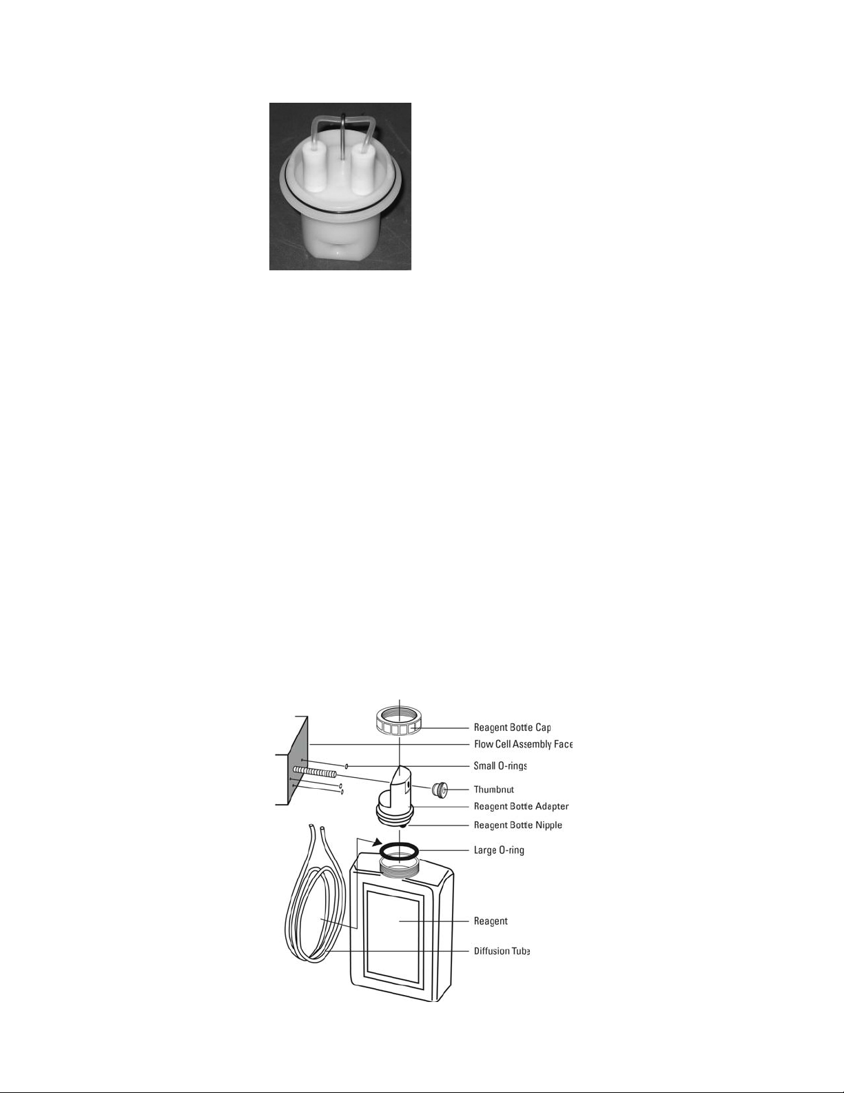
Figure 13: Reagent Bottle Assembly
3. Holding the bottle steady with one hand, install the reagent bottle adapter assembly by
tightening its cap onto the bottle. Ensure that the bottle label is oriented so that it will be
visible when the entire assembly is mounted to the instrument.
4. Replace the large single O-ring in the reagent bottle adapter assembly. Use needle nose
pliers if necessary.
5. Replace all three O-rings on the face of the reagent manifold. Refer to Figure 13.
6. Slide the reagent bottle adapter assembly over the threaded screw of the re agent ma nifold.
Refer to Figure 13.
7. Tighten the thumb nut to secure the connection.
Thermo Scientific Orion 2111XP Sodium Analyzer | 19
Page 23
2 | Analyzer Preparation
Section
Installation of Ammonia Reagent and Diffusion
Tubing
WARNING: The reagent is hazardous. Use protective glasses and gloves. Refer to the bottle
label for precautions and work in a fume hood or well-ventilated area.
Note: Turn off the air pump before beginning this procedure; otherwise, the air pump will splatter
the reagent outward as the bottle is removed.
1. Remove the thumbnut and slide the bottle adaptor from the flow cell.
2. Unscrew the cap and lift the bottle adaptor from the reagent bottle.
3. Remove both ends of the old diffusion tubing from the reagent bottle adaptor nipples.
Properly dispose of spent reagent and tubing.
4. Fit the ends of the new diffusion tubing over the bottle adaptor nipples.
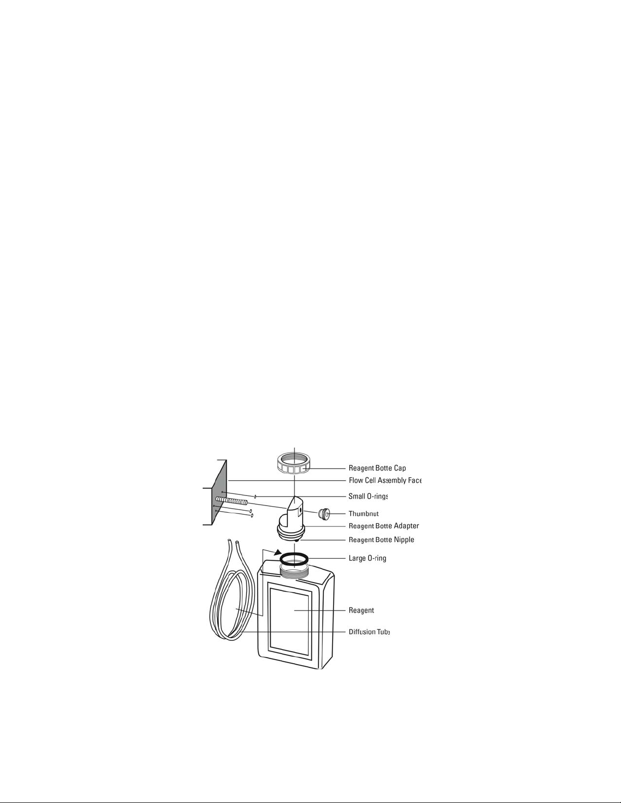
5. In a fume hood or outdoors, carefu lly remove the cap from a new reagent bottle.
6. Make sure that the large O-ring is between the reagent bottle an d bottle adaptor (ensu ring it
is not pinched). Slide the diffusion tubing loops into the reagent bottle and screw the bottle
adaptor onto the new reagent bottle.
Figure 14: Reagent Bottle Assembly
7. Ensure that the three small O-rings are in place on the flow cell.
8. Re-attach the bottle adaptor/reagent bottle assembly to the flow cell by sliding it onto the
screw and tightening the thumbnut. The bottle adaptor can be rotated to allow correct
positioning on the analyzer.
| Orion 2111XP Sodium Analyzer Thermo Scientific
20
Page 24
2 | Analyzer Preparation
Section
Installation of New Electrode Cables
1. Unpack the electrode cables.
2. Feed the tinned wires through the cable gland assemblies with the holes (2 or 1).
3. Follow the terminal assignments shown in Figure 9 for the proper electrode cable wiring
location.
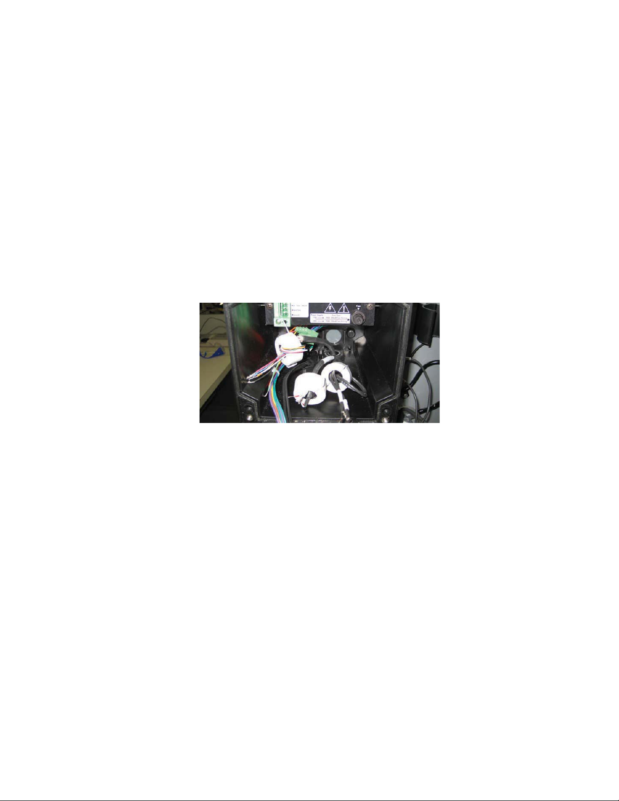
Ferrite Installation
1. Open the ferrite using a flat tip screwdriver to lift the latch of the ferrite.
2. Feed the cable wires through the cen ter of the ferrite and then loop the cable wires around
the ferrite core and through the center of the ferrite again.
3. Place the ferrite at the bottom of the analyzer chassis, near its edge. Adjust the ferrite
location on the cable so the ferrite is near the top of the cable.
Figure 15: Ferrite Installation
Conditioning and Installation of a New Sodium Electrode
The Thermo Scientific Orion sodium electrode (Cat. No. 210045) must be used in conjunction
with the Thermo Scientific Orion reference electrode (Cat. No. 210056).
WARNING: Be sure to read and observe the following requirements. On ly the sodium sensing
electrode is etched. Do not etch the reference electrode. Safety glasses must be worn during
the entire conditioning procedure. Gloves must be worn while etching the electrode.
1. Unpack the sodium electrode (Cat. No. 210045) and carefully remove the protective cap.
Save the cap for future storage of the electrode.
2. Immerse the sodium electrode in the bottle of etch solution (Cat. No.181113) for one minute.
3. Remove the sodium electrode from the bottle of etch solution and rinse it with deionized
water. Gently blot the electrode bulb with a clean lab tissue paper. Rinse the electrode
again with deionized water.
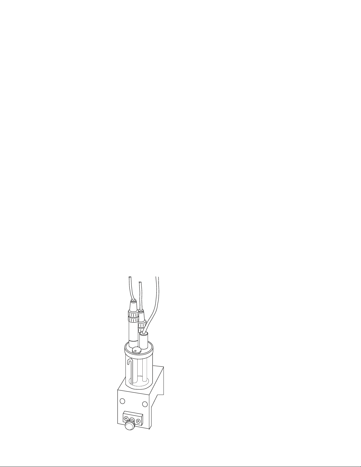
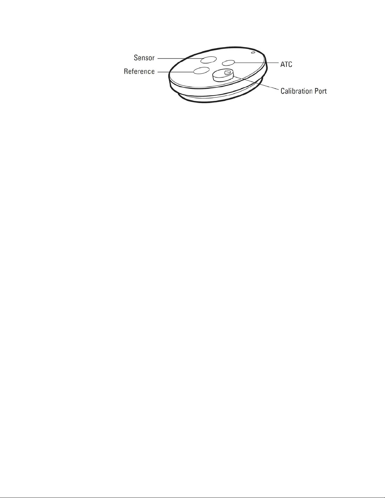
4. Insert the sodium electrode into its port in the flow cell cap. Refer to Figure 16 for the
location.
Thermo Scientific Orion 2111XP Sodium Analyzer | 21
Page 25
2 | Analyzer Preparation
Section
Figure 16: Flow Cell Cap
5. Plug the electrode cable marked “Sensing” into the top of the electrode. Be sure to push
back the black cap to verify a secure connection between the male and female pin
connection prior to tightening.
6. Tighten the screw cap connection to the cable.
Note: Do not twist the cable while tightening the connection. Twisting may cause damage
requiring premature replacement of the cable.
7. Wait at least one hour before calibrating the analyzer.
Installation of the ATC Probe
The automatic temperature compensation (ATC) probe (Cat. No. 2100TP) is already connected
to the correct terminal for temperature upon delivery.
1. Insert the ATC probe into its port in the flow cell cap. Refer to Figure 16 for the location.
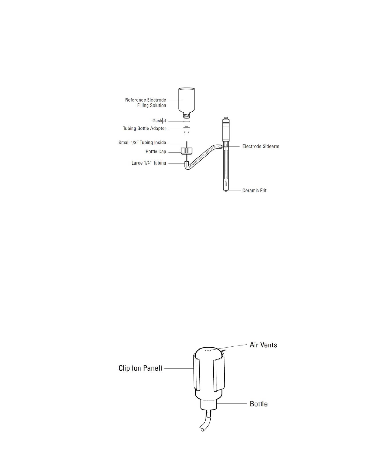
Installation of a New Reference Electrode
1. Unpack the reference electrode (Cat. No. 210056) and its instruction sheet from the
shipping box.
2. Carefully remove the protective caps from the bottom and sidearm of the reference
electrode. Save the caps for future storage of the electrode.
3. Shake out as much of the fill solution as possible through the sidearm. Drain the fill solution
through the sidearm or use a pipet or syringe.
4. While passing the 1/8 inch tubing into electrode sidearm, slide the 1/4 inch tubing over the
sidearm. The outside tubing should extend 3/8 to 1/2 inch over sidearm. Re fer to
Figure 17.
5. Remove the cap and fluid seal from reference electrode fill solution bottle (Cat. No.
181073). Hold the bottle in an upright position. Check that the rubber gasket is properly
aligned, and then connect the cap end of the tubing assembly to the bottle. The 1/8 inch
tubing should extend into the bottle.
6. Hold the reservoir bottle above the electrode with the bottle cap end down. The electrode
should be horizontal with the sidearm pointing up. Gently shake the electrode to allow any
trapped air bubbles to rise into the bottle as the electrode fills with solution.
| Orion 2111XP Sodium Analyzer Thermo Scientific
22
Page 26
Section
Figure 17: Reference Electrode with Filling
Solution
2 | Analyzer Preparation
7. Dry off the ceramic frit on the base of the electrode with a lint-free wipe. Squeeze the bot tle
for a few seconds. A small amount of filling solution should bead up on the frit surface ,
indicating good filling solution flow. If no moisture is visi ble, the electrode is clogged and
should be cleaned or replaced.
8. Invert the electrolyte bottl e and snap it into the clip. Refer to Figure 18. Use the pushpin
supplied with the reference electrode to pu ncture three air vents on the bottom of the filling
solution bottle.
CAUTION: Failure to vent the filling solution bottle will lead to noisy and drifting output
signals.
9. Plug the electrode cable marked “Ref erence” into the top of the electrode, and tighten the
screw cap. Be sure to push back the black cap to verify a secure connection between the
male and female pin connection prior to tightening.
10. Tight en the screw cap connection to the cable.
Note: Do not twist the cable while tightening the connection. Twisting ma y cause damage
requiring premature replacement of the cable.
11. Insert the reference electrode into its port in the flow cell cap. Refer Figure 16 for the
location.
Figure 18: Reference Mounting Clip
Thermo Scientific Orion 2111XP Sodium Analyzer | 23
Page 27
S E C T I O N
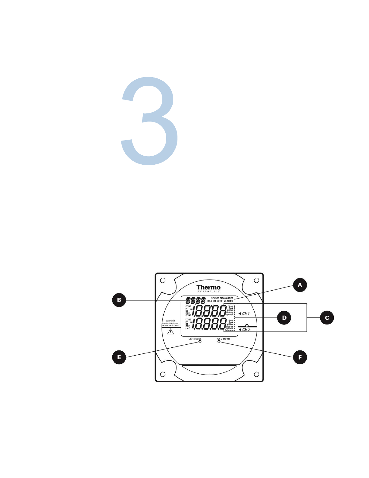
Figure 19: Faceplate
3 Analyzer Operation
Description of Basic Controls
24 | Orion 2111XP Sodium Analyzer Thermo Scientific
A
Page 28
Section
Parameter Location on Display Options Default
A
B
B
CED
F
3 | Analyzer Operation
Mode Indicator Top right corner of display
Marquee Display Top left corner of display
Temperature Display Celsius
Main Data Display
Measurement Units
Channel 1 Status
Indicator
Middle line and bottom line
of display
Left and right side of
middle and bottom display
lines
Below display screen, to
the left of
HOLD, CAL, SETUP, MEASURE,
DIAGNOSTIC
Analyzer provides prompts for operator
using the scrolling message
ISE board: concentration
pH/mV board: pH or mV
Conductivity board: conductivity, resistivity,
salinity, concentration or TDS
ISE board: ppm or ppb, auto-ranging
pH/mV board: pH or mV
Conductivity board: µS/cm or mS/cm
(conductivity), M-cm (resistivity),
SAL1 or SAL2 in the marquee (salinity),
PCT1 or PCT2 in the marquee
(concentration) and TDS1 or TDS2 in the
marquee (TDS)
Green LED indicates that channel is OK
Orange LED indicates a channel warning
Red LED indicates a channel failure
MEASURE
In the measure mode, if an ATC
probe is connected the default is the
actual measured temperature and if
no ATC probe is connected the
default is 25 °C
Depends on type of board installed
and selected measurement
parameter
Depends on type of board installed
and selected measurement
parameter
At initial installation, the red LED
indicates that the electrode or probe
needs to be installed and calibrated.
Channel 2 Status
Indicator
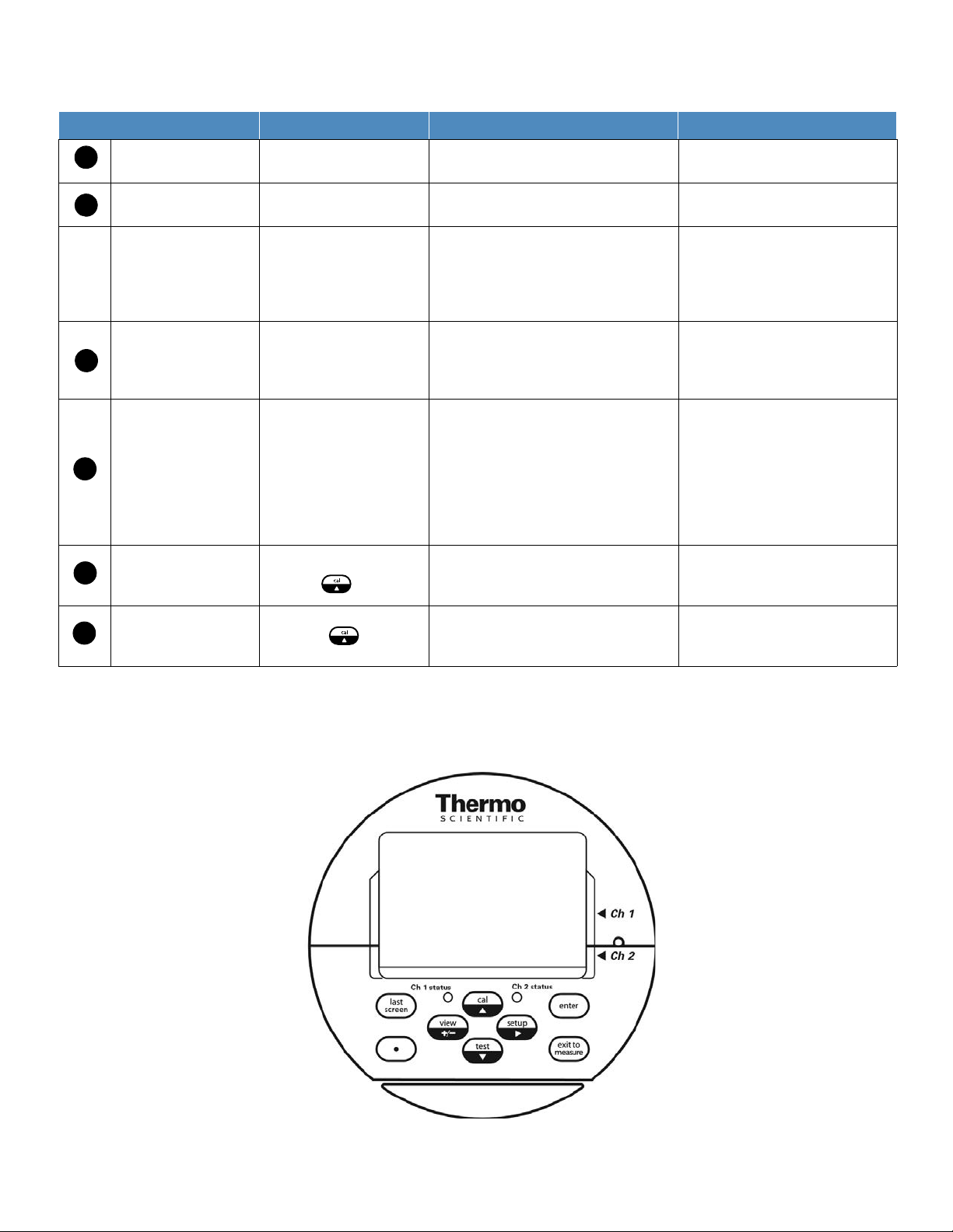
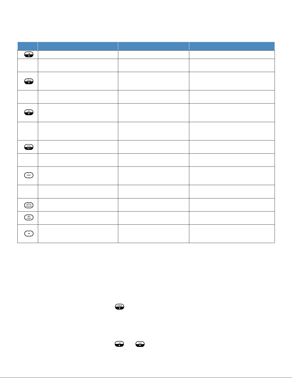
Figure 20: Keypad Icons
Below display screen, to
the right of
Green LED indicates that channel is OK
Orange LED indicates a channel warning
Red LED indicates a channel failure
Description of Keypad Icons
At initial installation, the red LED
indicates that the electrode or probe
needs to be installed and calibrated.
Thermo Scientific Orion 2111XP Sodium Analyzer | 25
Page 29

Section
Parameter Location on Display Options Default
A
B
B
CED
F
3 | Analyzer Operation
Mode Indicator Top right corner of display
Marquee Display Top left corner of display
Temperature Display Celsius
Main Data Display
Measurement Units
Channel 1 Status
Indicator
Middle line and bottom line
of display
Left and right side of
middle and bottom display
lines
Below display screen, to
the left of
HOLD, CAL, SETUP, MEASURE,
DIAGNOSTIC
Analyzer provides prompts for operator
using the scrolling message
ISE board: concentration
pH/mV board: pH or mV
Conductivity board: conductivity, resistivity,
salinity, concentration or TDS
ISE board: ppm or ppb, auto-ranging
pH/mV board: pH or mV
Conductivity board: µS/cm or mS/cm
(conductivity), M-cm (resistivity),
SAL1 or SAL2 in the marquee (salinity),
PCT1 or PCT2 in the marquee
(concentration) and TDS1 or TDS2 in the
marquee (TDS)
Green LED indicates that channel is OK
Orange LED indicates a channel warning
Red LED indicates a channel failure
MEASURE
In the measure mode, if an ATC
probe is connected the default is the
actual measured temperature and if
no ATC probe is connected the
default is 25 °C
Depends on type of board installed
and selected measurement
parameter
Depends on type of board installed
and selected measurement
parameter
At initial installation, the red LED
indicates that the electrode or probe
needs to be installed and calibrated.
Channel 2 Status
Indicator
Figure 20: Keypad Icons
Below display screen, to
the right of
Green LED indicates that channel is OK
Orange LED indicates a channel warning
Red LED indicates a channel failure
Description of Keypad Icons
At initial installation, the red LED
indicates that the electrode or probe
needs to be installed and calibrated.
Thermo Scientific Orion 2111XP Sodium Analyzer | 25
Page 30
3 | Analyzer Operation
Section
Key Parameter/Mode Action Operational Selections
Enters calibration mode Calibration mode with operator prompts Depends on type of board installed
Scrolls up digit numbers Scrolls up through a
list of options in setup and cal modes
Enters setup mode
Moves to the next digit Use to edit values
Enters test mode
Scroll down digit numbers
Scroll down through a list of options in setup
and cal modes
Enters log view mode
+/- function
Enter function
Enter function (in test mode only)
Exit to measure function
Last screen function
Decimal point function
Use to edit numeric values Use to
select available options
System setup mode at the last parameter used by the operator
Use to advance through sequence of
displays DIAGNOSTICS will appear in
top right of screen
Use to edit numeric values Use to
select available options
Use to view data in calibration,
measure and status logs
Enters negative/positive sign when
editing numbers
Use to accept value or selection
displayed on screen and store value or
selection in memory
Use in test mode to display additional
information for selected menus
Use to exit setup or cal modes and
enter the measure mode
Use in setup and test modes to return
to the previous screen or menu
Use to set the decimal point position in
certain menus with numbers that
require a decimal point
0 through 9 selectable by digit, first digit sometimes selectable 0 through 19
PASS, DATE, TIME, LOG, RSET, DISP, CH1,
CH2, MDL, MEAS, HOLD, TCMP, TADJ, ALRM,
mA1, mA2, mADJ, TEST, CAL, PH, COND, DKA
When moved to final digit, the system will wrap
around to first digit
0 through 9 selectable by digit, first digit sometimes selectable 0 through 1
Analyzer automatically enters measure mode
when first turned on and after calibration
Use of the Setup Mode
Before the first sample measurements can be taken, the setup mode should be programmed
and a successful calibration must be performed by the operator and stored in the memory of the
analyzer.
Navigating Tips for the Setup Mode
Press to enter the setup mode.
SETUP appears in the mode indicator screen.
HOLD is displayed while in the setup mode.
The analyzer will enter the setup mode at the last menu that was used by the operator.
Press and to loop through the menu options.
| Orion 2111XP Sodium Analyzer Thermo Scientific
26
Page 31

3 | Analyzer Operation
Section
Press to select the desired menu option and set the menu option parameters.
Press and to:
Scroll between On and OFF for the selected menu option.
Scroll and set the first digit value to 0 through 19.
Scroll and set the remaining digit values to 0 through 9.
Press to move to the next digit (scroll right) to set each digit value (4 digits maximum).
Press to save the entered parameter for the selected menu option.
Press to exit the current screen and return to the previous screen.
Press to exit the setup mode and return to the measure mode. If is pressed,
will not return the operator to the setup mode.The operator must reenter the setup
mode by pressing .
Channel Specific Menu Options in the Setup Mode
If a single channel analyzer is in use, all of the menu options are accessible by pressing
/ in the setup mode. The system will loop through the menu options and all of the
menu options are in the same level of the setup mode.
If a two channel analyzer is in use, only the general menu options are accessible by pressing
/ in the setup mode. The channel 1 and channel 2 specific menu options must be
accessed by selecting the CH1 or CH2 menu options in the setup mode. The channel specific
menu options are in the second level in setup mode. If a two channel analyzer is in use, make
sure to program both the channel 1 and channel 2 menu options in the setup mode.
Using Password Protection
The default password is 0000 – indicates password protection has not been activated.
System password: Management secured password protection of setup mode and calibration
process.
Calibration password: Operator secured password for protection of calibration process only.
If password(s) are activated:
System prompts operator to enter system password:
Marquee: ENTER PASSWORD
Main display top: PASS
Main display bottom: 0000 (flashing)
Correct password – Allows operator to enter setup mode for custom programming options.
Incorrect password – Password incorrect or not entered correctly.
System password:
Thermo Scientific Orion 2111XP Sodium Analyzer | 27
Page 32

3 | Analyzer Operation
Section
Marquee: SYSTEM PASS INCORRECT
Main display: E035
Calibration password:
Marquee: CAL PASS INCORRECT
Main display: E034
Verify password and re-enter it.
If password(s) are de-activated:
System enters the setup mode at the last setup menu option used by the operator.
Marquee: Flashes current menu option
Main display: SEL SCrn
Setup Mode Overview
The setup mode features programmable menu options. The order of the menu options is
dependent on the direction the operator scrolls by pressing or . The menu options
are listed below by pressing .
General Setup Mode Menu Options
The following menu options are displayed in the main setup mode of one and two channel
analyzers.
PASS
Set either of two password options:
System password – Setup settings protected, accessed by authorized operators only
Calibration password – Calibration menu data is protected, accessed by auth orized
operators only
Default password is 0000 – Disables both passwords
Forgot your password? Contact Technical Support at 1-800-225-1480
DATE
Set the date in US or Europe format:
Enter month, day and year
Default date – System will continue to keep date and time due to battery back up, operator
must set in accordance to local time zone
If the battery is removed, the system will show 01/01/2000
| Orion 2111XP Sodium Analyzer Thermo Scientific
28
Page 33

3 | Analyzer Operation
Section
TIME
Set the time:
Enter hour and minutes in 24 hour format
Default time – System will continue to keep date and time due to battery back up, operator
must set in accordance to local time zone
If the battery is removed the system will show 00:01
LOG
Set the data logging interval for measure log (calibration and error logs are accessed in the test
mode):
Set the log interval as hour:minute (HH:MM)
Default log interval is 00:00 – logging disabled
Minimum log interval is 1 minute, maximum log interval is 99 hours and 59 minutes
RSET
Reset the analyzer to factory defaults for setup parameters:
Used to troubleshoot the system (a hard reset can be performed if the keypad and software
are not responding, refer to Section 6, Resetting the Analyzer).
WARNING: Resetting the analyzer will lose all stored information including relay, logs and
calibration settings.
DISP
Set the automatic lighting options for th e backlit display:
AUtO – Brightness will change in response to ambient light source
On – Backlit display is always on
OFF – Backlit display is always off
Default display – AUtO
Channel Specific Setup Mode Menu Options
If a two channel analyzer is in use, the following setup mode menu options are specific to the
first channel of the 2111XP analyzer for sodium measurements. When a pH/ORP board or
conductivity board is installed on the second channel of the 2111XP analyzer, refer to the
Thermo Scientific Orion 2100 Series pH/ORP Analyzer and Conductivity Analyzer User Guide
for detailed instructions on the second channel setup mode menu options.
CH1 or CH2
The operator must select the channel number in the main setup mode (CH1 or CH2) and the
menu options that are relative to the measurement capability of that channel will be displayed. If
a one channel analyzer is being used, the CH1 and CH2 menus will not be shown.
Thermo Scientific Orion 2111XP Sodium Analyzer | 29
Page 34

3 | Analyzer Operation
Section
MEAS
Set the number of significant digits, mV display option and concentration units displayed when in
the measure mode:
Set the number of significant digits displayed measure mode
Scroll through 2, 3 or 4 significant digits
Default significant digits – 3
Enable mV values to be displayed on the second line
Scroll between On or OFF
Default mV setting – OFF
Set the displayed concentration units
Scroll through AUtO (automatically ranges from ppb to ppm), PPb (parts per billion, ppb),
or PP (parts per million, ppm)
Default displayed concentration units – AUtO
HOLD
Set the time that the system will remain on hold before the actual measurements are displayed
after a calibration:
Once the hold time expires, the system implements any programmed changes to settings in
the setup mode
After a calibration, the hold function allows the operator to rinse the electrodes prior to
recording actual measurement values
Default hold time – 30 minutes
TADJ
Adjust the temperature reading from the ATC probe by ± 5.0 °C:
Default adjustment – 0.0
°C
ALARM
Set up to three alarms – high, low and an error signaling contact:
Relays 1 and 2 (rLY1, rLY2) are normally open dry contacts used to set high an d low alarms
for measurement values
rLY1 and rLY2 options – OFF, HI, LO
Relay 3 (rLY3) is normally a closed contact that can be dedicated to errors (will close if
power to analyzer is lost), this alarm is influenced by calibration, errors and offline or hold
status
rLY3 options – OFF, CAL, HOLD, Err
Default setting for all alarms – OFF
| Orion 2111XP Sodium Analyzer Thermo Scientific
30
Page 35

3 | Analyzer Operation
Section
mA1
Set the mA1 analog current output:
Scroll between 4-20 mA or 0-20 mA current signals
The outputs share a common return, but are isolated from the main circuitry of the
analyzer
Default output current: 4-20 mA
Scroll between logarithmic (LOg) and linear (LIn) scale.
Set the low and high limits for the sensor output (SOUt)
Default – 1.0 ppb (low) and 100 ppb (high)
mA2
Set the mA2 analog current output:
Scroll between 4-20 mA or 0-20 mA current signals
The outputs share a common return, but are isolated from the main circuitry of the
analyzer
Default output current: 4-20 mA
Thermo Scientific Orion 2111XP Sodium Analyzer | 31
Page 36

3 | Analyzer Operation
Section
Select Sensor or Temperature for this output (SEnS and tEnP)
If Sense -
Scroll between logarithmic (LOg) and linear (LIn) scale for SOUt
Set the low and high limits for the sensor output (SOUt)
Default – 1.0 ppb (low) and 100 ppb (high)
If Temp -
Set the low and high limits for the temperature output (tOUt)
Default – 5.0 °C (low) and 45.0 °C (high)
mADJ
Set the mA offset adjustment value for the sensor mA1 and mA2 outputs:
Select OUT1 or OUT2 output
Scroll the numeric offset value and positive or negative offset value
Default mA offset – 00.0 mA
TEST
Test relays and analog output lines (DIAGNOSTICS will appear in th e mode indicator):
Method to activate/deactivate relays and outputs to be tested
Verify the accuracy of the analog outputs when used with an external loop calibrator
Provides the values and settings for the mA output and relays
mA output
4-20
The low and high values represented by mA1 and mA2
Relay status
Set RLY1, RLY2 and RLY3 status to OFF or On
CAL
Set calibration frequency in hours:
High limit is 19999 hours
Low limit is 00000 hours
Default setting – 720 hours
| Orion 2111XP Sodium Analyzer Thermo Scientific
32
Page 37

Section
DKA
Set values for customized Double Known Addition (DKA):
Programmable for volume (mL) of flow cell, concentration (ppm) and volume (mL) of
standard 1, concentration (ppm) and volume (mL) of standard 2, and whether the unit has
air values or not.
Flow cell volume: 95.0 mL
Default concentration (Std1): 19.1 ppm
Default volume addition (Std1): 0.10 mL
Default concentration (Std2): 192.0 ppm
Default volume addition (Std2): 0.10 mL
Default model is dependent on the software version.
Latest software version will have No-Air-Valves as the default.
Default Operator Action Scrolling Marquee Main Display Notes
3 | Analyzer Operation
SETUP (One Channel Analyzer)
Press to enter setup mode
SETUP appears as the mode indicator in the mode
window
HOLD is displayed while in the setup mode
The system will enter the setup mode at the last saved
menu option
Press to loop through the menu options
Press to select the desired menu option and enter
the submenu to customize setup parameters
PASS
DATE
TIME
LOG
RSET
DISP
MEAS
HOLD
TADJ
ALRM
mA1
mA2
mADJ
TEST
CAL
DKA
SEL SCrn The displayed menu options
depend on the measurement
capability of the analyzer.
Thermo Scientific Orion 2111XP Sodium Analyzer | 33
Page 38

3 | Analyzer Operation
Section
Default Operator Action Scrolling Marquee Main Display Notes
SETUP (Two Channel Analyzer)
Press to enter setup mode
SETUP appears as the mode indicator in
the mode window
HOLD is displayed while in the setup mode
The system will enter the setup mode at
the last saved menu option
PASS
DATE
TIME
LOG
RSET
DISP
CH1
MEAS
HOLD
TADJ
ALRM
mA1
mA2
mADJ
TEST
CAL
DKA
SEL SCrn
SEL SCrn
SEL SCrn
SEL SCrn
SEL SCrn
SEL SCrn
SEL SCrn
SEL CH1
SEL CH1
SEL CH1
SEL CH1
SEL CH1
SEL CH1
SEL CH1
SEL CH1
SEL CH1
SEL CH1
The list of menu options shown for CH2
are examples only. The displayed menu
options for CH2 depend on the
measurement capability of the channel.
If only one board is installed in the
analyzer, CH1 and CH2 will not be shown
in the scrolling marquee and all of the
menu options will be listed in the main
setup mode.
Press to loop through the menu
options
Press to select the desired menu
option and enter the submenu to customize
setup parameters
CH2
MDL
HOLD
TCMP
TADJ
ALRM
mA1
mA2
mADJ
TEST
CAL
PH
SEL SCrn
SEL CH2
SEL CH2
SEL CH2
SEL CH2
SEL CH2
SEL CH2
SEL CH2
SEL CH2
SEL CH2
SEL CH2
SEL CH2
| Orion 2111XP Sodium Analyzer Thermo Scientific
34
Page 39

3 | Analyzer Operation
Section
Default Operator Action Scrolling Marquee Main Display Notes
PASS PASS (flashing)
Press to set new passwords
0 0 0 0 SET-UP NEW SYSTEM
PASSWORD
Press /
Press to move to the next digit
Press /
remaining digits and press to move through
the remaining digits
Press to accept the system password and
advance to the next screen to set the calibration
password
0 0 0 0 SET-UP NEW
Press /
Press to move to the next digit
Press /
remaining digits and press to move through
the remaining digits
to set the first digit
to set the values of the
to set the first digit
to set the values of the
SET-UP NEW SYSTEM
PASSWORD
CALIBRATION PASSWORD
SET-UP NEW
CALIBRATION PASSWORD
SEL
SCrn
PASS
# # # #
(first digit flashing)
PASS
# # # #
(change flashing digit)
PASS
# # # #
(first digit flashing)
PASS
# # # #
(change flashing digit)
Do not scroll first
digit above 9
Do not scroll first
digit above 9
Press
return to the main setup mode
Press to scroll to the next menu
to accept the calibration password and
PASS (flashing) SEL
SCrn
Default Operator Action Scrolling Marquee Main Display Notes
DATE DATE (flashing) SEL
SCrn
Press to set the date
US SET USA OR EUROPEAN US (flashing)
Press
EUrO
Press
the next screen
/ to scroll between US and
to accept the setting and advance to
SET USA OR EUROPEAN US or EUrO
(flashing)
Thermo Scientific Orion 2111XP Sodium Analyzer | 35
Page 40

3 | Analyzer Operation
Section
Default Operator Action Scrolling Marquee Main Display Notes
01/01/
2000
Press /
Press to move to the next digit
Press /
remaining digits and press to move through
the remaining digits
Press
the main setup mode
Press to scroll to the next menu
to set the first digit
to set the values of the
to accept the date setting and return to
ENTER DATE MM/DD/YYYY
(US)
or
ENTER DATE DD/MM/YYYY
(EUrO)
ENTER DATE MM/DD/YYYY
(US)
or
ENTER DATE DD/MM/YYYY
(EUrO)
DATE
(flashing)
# #. # # (Month. Day)
2 0 # # (Year)
or
# #. # # (Day. Month)
2 0 # # (Year)
(first digit flashing)
# #. # # (Month. Day) 2
0 # # (Year)
or
# #. # # (Day. Month)
2 0 # # (Year)
(change flashing digit)
SEL
SCrn
Default Operator Action Scrolling Marquee Main Display Notes
TIME
TIME
(flashing)
SEL
SCrn
Press to set the time
00:01 ENTER 24HR TIME
HOUR/MINUTE
Press /
Press to move to the next digit
Press / to set the values of the
remaining digits and press to move through
the remaining digits
Press
the main setup mode
Press to scroll to the next menu
to set the first digit
to accept the time setting and return to
ENTER 24HR TIME
HOUR/ MINUTE
TIME
(flashing)
# # : # # (hour : minute)
(first digit flashing)
# # : # # (hour : minute)
(change flashing digit)
SEL
SCrn
Set in 24 hour time
format
| Orion 2111XP Sodium Analyzer Thermo Scientific
36
Page 41

Section
Default Operator Action Scrolling Marquee Main Display Notes
3 | Analyzer Operation
LOG
Press to set the log interval
00:00 SET LOG TIME IN HOUR/
Press /
Press to move to the next digit
Press /
remaining digits and press to move
through the remaining digits
Press
return to the main setup mode
Press to scroll to the next menu
to set the first digit
to set the values of the
to accept the log setting and
LOG
(flashing)
MINUTE
SET LOG TIME IN HOUR/
MINUTE
LOG
(flashing)
WARNING: The reset command will erase all operator settings, logs and calibration data. The
analyzer will need to be set up and calibrated again before it can resume operation.
SEL
SCrn
# # : # # (hour : minute)
LOg
(first digit flashing)
# # : # # (hour : minute)
LOg
(change flashing digit)
SEL
SCrn
To disable the log enter
0000 for the log interval
The minimum log interval is
1 minute and the maximum
log interval is 99 hours and
59 minutes
Default Operation Action Scrolling Marquee Main Display Notes
RSET
Press to reset the analyzer
To Reset the Analyzer:
Press
Press
Press
When the reset is complete, the system will
return to the measure mode. The operator will
need to re-enter the setup mode to continue
programming the setup parameters.
Press to return to the setup mode.
To Abort the Reset:
Press to return to the main setup mode
RSET
(flashing)
PUSH TEST VIEW ENTER
TO RESET
PUSH TEST VIEW ENTER
TO RESET
PRESS TEST VIEW
ENTER TO RESET
RSET
(flashing)
SEL
SCrn
rSEt
?
rSEt
?
rSEt
?
SEL
SCrn
This command resets all
previously set parameters to
factory default values. Use
this command only to set
the analyzer to original
factory setup values.
Press to scroll to the next menu
Thermo Scientific Orion 2111XP Sodium Analyzer | 37
Page 42

3 | Analyzer Operation
Section
WARNING: Resetting the analyzer will erase all stored information including relay, logs and
calibration settings.
Default Operation Action Scrolling Marquee Main Display Notes
DISP
Press to set the lighting option for the
backlit display
AUtO BACK LITE LItE
Press /
OFF and On settings
Press
and return to the main setup mode
Press to scroll to the next menu
to scroll through AUtO,
to accept the display setting
DISP
(flashing)
BACK LITE LItE
DISP
(flashing)
SEL
SCrn
AUtO
(flashing)
AUtO, OFF or On
(flashing)
SEL
SCrn
Note: The following menu options are for analyzers with two boards installed only. If two
channels are used, select the channel number in the main setup mode (CH1 or CH2) and
additional menu options will be displayed.
Default Operation Action Scrolling Marquee Main Display Notes
CH1 will not be shown in
scrolling marquee if only
one board is installed
CH1
Press
menus in the setup mode
Press to loop through the channel
specific menu options
Press
customize the parameter (refer to the menu
option displays that are shown on the
following pages for detailed instructions)
Press to scroll to the next menu
to set the channel 1 specific
to select a menu option and
CH1
(flashing)
MEAS
(flashing)
CH1
(flashing)
SEL
SCrn
SEL
CH1
SEL
SCrn
| Orion 2111XP Sodium Analyzer Thermo Scientific
38
Page 43

Section
Default Operation Action Scrolling Marquee Main Display Notes
3 | Analyzer Operation
CH2 will not be shown in
scrolling marquee if only
one board is installed
CH2
Press to set the channel 2 specific
menus in the setup mode
Press to loop through the channel
specific menu options
Press
customize the parameter (when a pH/ORP
or conductivity board is installed on channel
2, refer to the Thermo Scientific Orion 2100
Series pH/ORP Analyzer and Conductivity
Analyzer User Guide for detailed instructions
on the menu option displays)
Press to scroll to the next menu
to select a menu option and
CH2
(flashing)
MDL
(flashing)
CH2
(flashing)
SEL
SCrn
SEL
CH2
SEL
SCrn
Default Operation Action Scrolling Marquee Main Display Notes
MEAS
Press
3 SET NUMBER OF
Press /
and 4
Press
advance to the next screen
OFF SHOW MV ON SINGLE
Press /
OFF and On
Press to accept the setting and
advance to the next screen
AUtO SELECT ISE UNIT UnIt
to set measure parameters
to scroll through 2, 3
to accept the setting and
to scroll between
MEAS
(flashing)
SIGNIFICANT DIGITS
SET NUMBER OF
SIGNIFICANT DIGITS
CHANNEL DISPLAY
SHOW MV ON SINGLE
CHANNEL DISPLAY
SEL
SCrn
SIg
3
(flashing)
SIg
2, 3 or 4
(flashing)
OFF
(flashing)
OFF or On
(flashing)
AUtO
(flashing)
SEL CH1 or SEL CH2 on
main display of two channel
analyzer
Thermo Scientific Orion 2111XP Sodium Analyzer | 39
Page 44

3 | Analyzer Operation
Section
Default Operator Action Scrolling Marquee Main Display Notes
Press / to scroll through
AUtO, PPb and PP
Press
return to the main setup mode
Press to return to the channel
specific menu options in the setup mode
Press to scroll to the next menu
to accept the setting and
SELECT ISE UNIT UnIt
AUtO, PPb or PP
(flashing)
CH1 or CH2
(flashing)
MEAS
(flashing)
SEL
SCrn
SEL
SCrn
PP is used as an
abbreviation for ppm
Displayed for two
channel analyzer
Action required for two
channel analyzer
SEL CH1 or SEL CH2 on
main display of two
channel analyzer
Default Operation Action Scrolling Marquee Main Display Notes
SEL CH1 or SEL CH2 on
main display of two
channel analyzer
HOLD
Press to set the hold time
HOLD
(flashing)
SEL
SCrn
00:30 ENTER HOLD TIME
HOUR/MINUTE
Press /
Press to move to the next digit
Press / to set the values of
the remaining digits and press to
move through the remaining digits
Press
advance to the next screen
LASt ENTER HOLD STATE LAST
Press /
LASt and USEr
Press to accept the setting and
advance to the next screen
21.0 ENTER FIXED USER
Press /
Press to move to the next digit
Press /
the remaining digits and press to
move through the remaining digits
to set the first digit
to accept the setting and
to scroll between
to set the first digit
to set the values of
ENTER HOLD TIME
HOUR/MINUTE
OR USER VALUE
ENTER HOLD STATE LAST
OR USER VALUE
VALUE IN mA
ENTER FIXED USER
VALUE IN mA
# # : # #
(first digit flashing)
# # : # #
(change flashing digit)
LASt
(flashing
LASt or USEr (flashing)
# # . #
(first digit flashing)
# # . #
(change flashing digit)
Displayed if USEr was
selected in previous screen
Action required if USEr was
selected in previous screen
| Orion 2111XP Sodium Analyzer Thermo Scientific
40
Page 45

Section
Default Operator Action Scrolling Marquee Main Display Notes
Press / to set the first digit
Press to move to the next digit
Press /
the remaining digits and press to
move through the remaining digits
Press
advance to the next screen
OFF HOLD TO 22mA WHEN
Press /
and On
to set the values of
to accept the setting and
to scroll between OFF
ENTER FIXED USER
VALUE IN mA
ERROR
HOLD TO 22mA WHEN
ERROR
# # . #
(change flashing digit)
OFF
(flashing)
OFF or On
(flashing)
Action required if USEr was
selected in previous screen
Action required if USEr was
selected in previous screen
3 | Analyzer Operation
Press
return to the main setup mode
Press to return to the channel
specific menu options in the setup mode
Press to scroll to the next menu
to accept the setting and
CH1 or CH2
(flashing)
HOLD
(flashing)
SEL
SCrn
SEL
SCrn
Displayed for two channel
analyzer
Action required for two
channel analyzer
SEL CH1 or SEL CH2 on
main display of two
channel analyzer
Default Operation Action Scrolling Marquee Main Display Notes
TADJ
Press
adjustment value
0.0 C TEMPERATURE
Press /
Press to move to the next digit
Press / to set the value of
the next digit
Press to set a positive or negative
temperature value
to set the temperature
to set the first digit
TADJ
(flashing)
ADJUSTMENT
TEMPERATURE
ADJUSTMENT
TEMPERATURE
ADJUSTMENT
SEL
SCrn
AdJ
# . # c
(first digit flashing)
AdJ
# . # c
(change flashing digit)
AdJ
- # . # c
SEL CH1 or SEL CH2 on
main display of two
channel analyzer
The maximum
temperature adjustment is
± 5.0 °C
Press
return to the main setup mode
Thermo Scientific Orion 2111XP Sodium Analyzer | 41
to accept the setting and
Page 46

3 | Analyzer Operation
Section
Default Operator Action Scrolling Marquee Main Display Notes
CH1 or CH2
(flashing)
Press to return to the channel
specific menu options in the setup mode
TADJ
(flashing)
Press to scroll to the next menu
SEL
SCrn
SEL
SCrn
Displayed for two
channel analyzer
Action required for two
channel analyzer
SEL CH1 or SEL CH2 on
main display of two
channel analyzer
Default Operation Action Scrolling Marquee Main Display Notes
ALRM
Press
OFF SELECT ALARM 1 HIGH
Press /
OFF, HI and LO
to set the alarms
to scroll through
ALRM
(flashing)
LOW OR OFF
SELECT ALARM 1 HIGH
LOW OR OFF
SEL
SCrn
rLY1
OFF
(flashing)
rLY1
OFF, HI or LO
(flashing)
SEL CH1 or SEL CH2 on
main display of two
channel analyzer
Press
advance to the next screen
100 ppb Set the HI or LO value for rLY1:
Press to move the decimal point
Press /
Press to move to the next digit
Press /
the remaining digits and press to
move through the remaining digits
Press
advance to the next screen
OFF SELECT ALARM 2 HIGH
Press /
OFF, HI and LO
Press
advance to the next screen
to accept the setting and
to set the first digit
to set the values of
to accept the setting and
to scroll through
to accept the setting and
ENTER VALUE rLY1
LOW OR OFF
SELECT ALARM 2 HIGH
LOW OR OFF
# # . # #
(change flashing digit)
rLY2 OFF
(flashing)
rLY2
OFF, HI or LO
(flashing)
Displayed if HI or LO was
selected for rLY1 in
previous screen
Action required if HI or LO
was selected for rLY1 in
previous screen
| Orion 2111XP Sodium Analyzer Thermo Scientific
42
Page 47

Section
Default Operation Action Scrolling Marquee Main Display Notes
3 | Analyzer Operation
1 ppm Set the HI or LO value for rLY1:
Press to move the decimal point
Press /
Press to move to the next digit
Press /
the remaining digits and press to
move through the remaining digits
Press
advance to the next screen
OFF SELECT CALIBRATION
Press /
OFF, CAL, HOLd and Err
Press
return to the main setup mode
Press to return to the channel
specific menu options in the setup mode
to set the first digit
to set the values of
to accept the setting and
to scroll through
to accept the setting and
ENTER VALUE rLY2
HOLD
ERROR OR OFF
SELECT CALIBRATION
HOLD
ERROR OR OFF
CH1 or CH2
(flashing)
# # . # #
(change flashing digit
rLY3
OFF
(flashing)
rLY3
OFF, CAL, HOLd or Err
(flashing)
SEL
SCrn
Displayed if HI or LO was
selected for rLY2 in
previous screen
Action required if HI or LO
was selected for rLY2 in
previous screen
Displayed for two
channel analyzer
Action required for two
channel analyzer
ALRM
(flashing)
Press to scroll to the next menu
SEL
SCrn
SEL CH1 or SEL
CH2 on main display of two
channel analyzer
Configuring the analog output mA1
Default Operator Action Scrolling Marquee Main Display Notes
4-20
LOg
mA1
Press
Press /
4-20 and 0-20
Press
advance to the next screen
Press / to scroll between LOg
and LIn
Press
advance to the next screen
to set the analog output 1
to scroll between
to accept the setting and
to accept the setting and
mA1
(flashing)
SELECT 0-20 OR 4-20 4-20 or 0-20
SELECT LOG OR LINEAR
OUTPUT
SEL
SCrn
(flashing)
SOUt
LOg or LIn
(flashing)
SEL CH1 or SEL
CH2 on main display of two
channel analyzer
Thermo Scientific Orion 2111XP Sodium Analyzer | 43
Page 48

3 | Analyzer Operation
Section
Default Operator Action Scrolling Marquee Main Display Notes
1 ppb mA SENSOR OUTPUT
LOW VALUE
Press to move the decimal point
Press / to set the first digit
Press to move to the next digit
Press /
the remaining digits and press to
move through the remaining digits
Press to accept the setting and
advance to the next screen
100 ppb mA SENSOR OUTPUT
Press to move the decimal point
Press /
Press to move to the next digit
Press / to set the values of
the remaining digits and press to
move through the remaining digits
to set the values of
to set the first digit
mA SENSOR OUTPUT LOW
VALUE
HIGH VALUE
mA SENSOR OUTPUT
HIGH VALUE
LO
# # # . #
(first digit flashing)
LO
# # #. #
(change flashing digit)
HI
# # # . #
(first digit flashing)
HI
# # #. #
(change flashing digit)
Press
return to the main setup mode
Press to return to the channel
specific menu options in the setup mode
Press to scroll to the next menu
to accept the setting and
CH1 or CH2
(flashing)
mA1
(flashing)
SEL
SCrn
SEL
SCrn
Displayed for two
channel analyzer
Action required for two
channel analyzer
SEL CH1 or SEL CH2 on
main display of two
channel analyzer
Configuring the analog output mA2
Default Operator Action Scrolling Marquee Main Display Notes
4-20
mA2
Press
Press /
and 0-20
to set the analog output 2
to scroll between 4-20
mA2
(flashing)
SELECT 0-20 OR 4-20 4-20 or 0-20
SEL
SCrn
(flashing)
SEL CH1 or SEL CH2 on main
display of two channel analyzer
Press
advance to the next screen
| Orion 2111XP Sodium Analyzer Thermo Scientific
44
to accept the setting and
Page 49

Section
Default Operator Action Scrolling Marquee Main Display Notes
3 | Analyzer Operation
AOUT 2
SENSOR OR
TEMPERATURE
If choosing Sensor:
Press / to scroll between
SEnS or tEnP and select SEnS
Press to accept the setting and
advance to the next screen
LOg
1 ppb mA SENSOR OUTPUT
Press /
and LIn
Press
advance to the next screen
Press to move the decimal point
Press /
Press to move to the next digit
Press /
the remaining digits and press to
move through the remaining digits
to scroll between LOg
to accept the setting and
to set the first digit
to set the values of
AOUT 2
SENSOR OR
TEMPERATURE
SELECT LOG OR LINEAR
OUTPUT
LOW VALUE
mA SENSOR OUTPUT
LOW VALUE
SEnS
(flashing)
SEnS
(flashing)
LOg or LIn
(flashing)
LO
# # # . #
(first digit flashing)
LO
# # #. #
(change flashing digit)
Press
advance to the next screen
100 ppb mA SENSOR OUTPUT
Press to move the decimal point
Press /
Press to move to the next digit
Press /
the remaining digits and press to
move through the remaining digits
Press
advance to the next screen
Press to return to the channel
specific menu options in the setup mode
to accept the setting and
to set the first digit
to set the values of
to accept the setting and
HIGH VALUE
mA SENSOR OUTPUT
HIGH VALUE
CH1 or CH2
(flashing)
mA2
(flashing)
HI
# # # . #
(first digit flashing)
HI
# # #. #
(change flashing digit)
SEL
SCrn
SEL
SCrn
Displayed for two
channel analyzer
Action required for two
channel analyzer
SEL CH1 or SEL CH2 on
main display of two
channel analyzer
Thermo Scientific Orion 2111XP Sodium Analyzer | 45
Page 50

3 | Analyzer Operation
Section
Default Operator Action Scrolling Marquee Main Display Notes
Press to scroll to the next menu
If choosing temperature:
Press / to scroll between
SEnS or tEnP and select tEnP
Press to accept the setting and
advance to the next screen
05.0 C
Press /
Press to move to the next digit
Press /
the remaining digits and press to set
a positive or negative temperature value
Press
advance to the next screen
45.0 C mA TEMP
Press /
Press to move to the next digit
Press /
to set the first digit
to set the values of
to accept the setting and
to set the first digit
to set the values of
AOUT 2
SENSOR OR
TEMPERATURE
mA TEMP
OUTPUT LOW VALUE
mA TEMP
OUTPUT LOW VALUE
OUTPUT HIGH VALUE
mA TEMP
OUTPUT HIGH VALUE
tEnP
(flashing)
LO
# # . # c
(first digit flashing)
LO
# #.# C
(change flashing digit)
HI
# # . # c
(first digit flashing)
HI
#
# . # c
(change flashing digit)
the remaining digits and press to
move through the remaining digits
Press to accept the setting and
return to the main setup mode
CH1 or CH2
(flashing)
Press to return to the channel
specific menu options in the setup mode
mA2
(flashing)
Press to scroll to the next menu
| Orion 2111XP Sodium Analyzer Thermo Scientific
46
SEL
SCrn
SEL
SCrn
Displayed for two
channel analyzer
Action required for two
channel analyzer
SEL CH1 or SEL CH2 on
main display of two
channel analyzer
Page 51

Section
Default Operator Action Scrolling Marquee Main Display Notes
3 | Analyzer Operation
mADJ
Press
temperature mA offset values
Press /
OUT1 or OUT2 and select OUT1
Press to accept the setting and
advance to the next screen
0.00 mA1 OUTPUT
Press /
offset value
Press to set a positive or negative
sensor mA offset
Press
return to the main setup mode
to set the sensor and
to scroll between
to set the sensor mA
to accept the setting and
mADJ
(flashing)
SELECT mA1 OR mA2
OUTPUT
SELECT mA1 OR mA2
OUTPUT
ADJUSTMENT
mA1 OUTPUT
ADJUSTMENT
CH1 or CH2
(flashing)
SEL
SCrn
OUT1 or OUT2
(flashing)
OUT1
(flashing)
AdJ
0 . 0 #
(last flashing digit)
AdJ
0 . 0 #
(change flashing digit)
SEL
SCrn
SEL CH1 or SEL
CH2 on main display of two
channel analyzer
Displayed for two
channel analyzer
Press to return to the channel
specific menu options in the setup mode
mADJ
(flashing)
Press
temperature mA offset values
Press /
OUT1 or OUT2 and select OUT2
Press
advance to the next screen
0.00 mA2 OUTPUT
Press /
temperature mA offset value
Press to set a positive or negative
temperature mA offset
to set the sensor and
to scroll between
to accept the setting and
to set the
SELECT mA1 OR mA2
OUTPUT
SELECT mA1 OR mA2
OUTPUT
ADJUSTMENT
mA2 OUTPUT
ADJUSTMENT
SEL
SCrn
OUT1 or OUT2
(flashing)
OUT2
(flashing)
AdJ
0 . 0 #
(last flashing digit)
AdJ
0 . 0 #
(change flashing digit)
Action required for two
channel analyzer
SEL CH1 or SEL CH2 on
main display of two
channel analyzer
Thermo Scientific Orion 2111XP Sodium Analyzer | 47
Page 52

3 | Analyzer Operation
Section
Default Operator Action Scrolling Marquee Main Display Notes
Press to accept the setting and
return to the main setup mode
CH1 or CH2
(flashing)
SEL
SCrn
Displayed for two
channel analyzer
Press to return to the channel
specific menu options in the setup mode
Press to scroll to the next menu
mADJ
(flashing)
SEL
SCrn
Action required for two
channel analyzer
SEL CH1 or SEL CH2 on
main display of two
channel analyzer
Default Operator Action Scrolling Marquee Main Display Notes
SEL CH1 or SEL CH2 on
main display of two
channel analyzer
4-20
TEST
Press to test the mA outputs (4-20)
and relays (rLY)
To Test OUT2
Press / to scroll between
4-20 and rLY settings and select 4-20
Press
to test 4-20 outputs
TEST
(flashing)
SELECT mA OR RELAY tESt
SEL
SCrn
4 - 20
(flashing)
Actual
low value
displayed
Actual
high value
displayed
Press / to scroll between
OUT1 and OUT2 settings and select OUT2
Press to display the OUT2 low
value
Press to display the OUT2 high
value
Press
to the main setup mod
to accept the test and return
SELECT mA1 OR mA2
OUTPUT
SELECT mA1 OR mA2
OUTPUT
mA TEMP OUTPUT
LOW VALUE
mA TEMP OUTPUT
HIGH VALUE
CH1 or CH2
(flashing)
4 - 20
OUT1 or OUT2
(flashing)
4 - 20
OUT1 or OUT2
(flashing)
LO
# . # c
HI
# . # c
SEL
SCrn
4.0 mA are sourced at
output terminal 11
20 mA are sourced at
output terminal 11
Display for two
channel analyzer only
| Orion 2111XP Sodium Analyzer Thermo Scientific
48
Page 53

Section
Default Operator Action Scrolling Marquee Main Display Notes
3 | Analyzer Operation
4-20
Actual
low value
displayed
Press to return to the channel
specific menu options in the setup mode
Press
and relays (rLY)
To Test mA1:
Press /
4-20 and rLY settings and select 4-20
Press
Press / to scroll between
OUT1 and OUT2 settings and select OUT1
Press to display the mA1 low value
to test the mA outputs (4-20)
to scroll between
to test 4-20 outputs
TEST
(flashing)
SELECT mA OR RELAY tESt 4 - 20
SELECT mA1 OR mA2
OUTPUT
SELECT mA1 OR mA2
OUTPUT
mA SENSOR OUTPUT
LOW VALUE
SEL
SCrn
(flashing)
4 - 20
OUT1 or OUT2
(flashing)
4 - 20
OUT1
(flashing)
LO
# . #
Action required for two
channel analyzer only
SEL CH1 or SEL CH2 on
main display of two
channel analyzer
4.0 mA are sourced at
output terminal 9
Actual
high value
displayed
4-20
Press to display the mA1 high
value
Press
to the main setup mode
Press to return to the channel
specific menu options in the setup mode
Press
(4-20) and relays (rLY)
To Test rLY
Press /
4-20 and rLY settings and select rLY
to accept the test and return
to test the mA outputs
to scroll between
mA SENSOR OUTPUT
HIGH VALUE
CH1 or CH2
(flashing)
TEST
(flashing)
SELECT mA OR RELAY tESt
HI
#. #
SEL
SCrn
SEL
SCrn
rLY
(flashing)
20.0 mA are sourced at
output terminal 9
Display for two
channel analyzer only
Action required for two
channel analyzer only
SEL CH1 or SEL CH2 on
main display of two
channel analyzer
Thermo Scientific Orion 2111XP Sodium Analyzer | 49
Page 54

3 | Analyzer Operation
Section
Default Operator Action Scrolling Marquee Main Display Notes
Actual
rLY1
status
Actual
rLY2
status
Actual
rLY3
status
Press
Press / to set the rLY1
setting OFF or On
Press to accept the rLY1 test and
move to the rLY2 test
Press /
setting OFF or On
Press
move to the rLY3 test
Press /
setting OFF or On
Press
return to the main setup mode
Press to return to the channel
specific menu options in the setup mode
to test relay outputs
to set the rLY2
to accept the rLY2 test and
to set the rLY3
to accept the rLY3 test and
USE ARROWS TO
TOGGLE RELAY 1
USE ARROWS TO
TOGGLE RELAY 2
USE ARROWS TO
TOGGLE RELAY 3
CH1 or CH2
(flashing)
TEST
(flashing)
rLY1
OFF or On
rLY2
OFF or On
rLY3
OFF or On
SEL
SCrn
SEL
SCrn
Relay contact according to
screen indication
Relay contact according to
screen indication
Relay contact according to
screen indication
Display for two
channel analyzer only
Action required for two
channel analyzer only
SEL CH1 or SEL CH2 on
main display of two
channel analyzer
Press to scroll to the next menu
Default Operator Action Scrolling Marquee Main Display Notes
CAL
Press to set the required calibration
frequency
0720 ENTER CALIBRATION
Press / to set the first digit
Press to move to the next digit
Press / to set the values of
the remaining digits and press to
move through the remaining digits
Press
return to the main setup mode
to accept the setting and
CAL
(flashing)
FREQUENCY IN HOURS
ENTER CALIBRATION
FREQUENCY IN HOURS
CH1 or CH2
(flashing)
SEL
SCrn
CAL
# # # #
(first digit flashing)
CAL
# # # #
(change flashing digit)
SEL
SCrn
SEL CH1 or SEL CH2 on
main display of two
channel analyzer
To disable the calibration
alarm, set the value to 0000
Display for two
channel analyzer only
| Orion 2111XP Sodium Analyzer Thermo Scientific
50
Page 55

Section
Default Operator Action Scrolling Marquee Main Display Notes
3 | Analyzer Operation
Press to return to the channel
specific menu options in the setup mode
Press to scroll to the next menu
CAL
(flashing)
SEL
SCrn
Action required for two
channel analyzer
SEL CH1 or SEL CH2 on
main display of two
channel analyzer
Default Operator Action Scrolling Marquee Main Display Notes
DKA
Press
for the electrode calibration
95.0 mL ENTER FLOW CELL
Press /
Press to move to the next digit
Press / to set the values of
the remaining digits and press to
move through the remaining digits
to set custom DKA settings
to set the first digit
DKA
(flashing)
VOLUME IN mL
ENTER FLOW CELL
VOLUME IN mL
SEL
SCrn
FCEL
# # #. #
(flashing)
FCEL
# # #. #
(change flashing digit)
SEL CH1 or SEL CH2 on
main display of two channel
analyzer
Press to accept the setting and
advance to the next screen
19.1 ppm SET STD1
CONCENTRATION
Press / to set the first digit
Press to move to the next digit
Press /
the remaining digits and press to
move through the remaining digits
Press
advance to the next screen
0.10 mL SET STD1 VOLUME IN mL Std1
to set the values of
to accept the setting and
SET STD1
CONCENTRATION
COnC
# # # . #
(flashing)
COnC
# # #. #
(change flashing digit)
# # . # #
(flashing)
Thermo Scientific Orion 2111XP Sodium Analyzer | 51
Page 56

3 | Analyzer Operation
Section
Default Operator Action Scrolling Marquee Main Display Notes
Press / to set the first digit
Press to move to the next digit
Press /
the remaining digits and press to
move through the remaining digits
Press
advance to the next screen
192.0
ppm
Press /
Press to move to the next digit
Press / to set the values of
the remaining digits and press to
move through the remaining digits
Press
advance to the next screen
0.10 mL SET STD2 VOLUME IN mL Std2
Press /
Press to move to the next digit
Press / to set the values of
the remaining digits and press to
move through the remaining digits
to set the values of
to accept the setting and
to set the first digit
to accept the setting and
to set the first digit
SET STD1 VOLUME IN mL
Std1
SET STD2
CONCENTRATION
SET STD2
CONCENTRATION
SET STD2 VOLUME IN mL Std2
# # . # #
(change flashing digit)
COnC
# # # . #
(flashing)
COnC
# # #. #
(change flashing digit)
# # . # #
(flashing)
# # . # #
(change flashing digit)
Press
return to the main setup mode
Press to return to the channel
specific menu options in the setup mode
Press to scroll to the next menu
| Orion 2111XP Sodium Analyzer Thermo Scientific
52
to accept the setting and
CH1 or CH2
(flashing)
DKA
(flashing)
SEL
SCrn
SEL
SCrn
Displayed for two
channel analyzer
Action required for two
channel analyzer
SEL CH1 or SEL CH2 on
main display of two
channel analyzer
Page 57

3 | Analyzer Operation
Section
Shutdown and Start-Up Procedure
The following steps should be taken if a loss of sample flow is expected for more than one day.
These procedures will prevent possible build-up of caustic reagent vapo rs in the analyzer.
Shutdown
WARNING: Be sure to read and observe the following requirements.
Air Pump Shutdown
DANGER: Turn off the air pump prior to removing reagent bottle. The air pump will spatter
caustic reagent outward as bottle is removed. Wear rubber gloves and safety goggles to avoi d
possible injury from reagent residues in the system.
1. To access air pump, press .
2. Press / to scroll though parameters until TEST appears in marquee window.
3. Press to access the TEST menu.
4. Press / to scroll through the TEST menu until AIr appears in the main display.
5. Press .
6. Press / to toggle between On and OFF settings for the air pump power. Select
the OFF setting. Changing the air pump setting to On or OFF will be indicated by a click
sound.
7. Press to accept the setting and return to the TEST menu.
8. Press to return to the measure mode.
Analyzer Shutdown
1. Shut off sample flow prior to the analyzer inlet. Refer to Section 4, Flow Cell Operation.
2. Disconnect the power. Refer to Section 2, Wiring the Analyzer.
3. Drain the flow cell.
4. Remove the reagent bottle and store it in a well-ventilated area such as a laboratory fume
hood.
5. Carefully pull the sodium and reference electrodes out of the top of the flow cell and let
them hang by their connectors.
6. Locate the protective cap from reference ele c trode kit and place it on the base of the
reference electrode to prevent it from drying out.
Thermo Scientific Orion 2111XP Sodium Analyzer | 53
Page 58

3 | Analyzer Operation
Section
Start-Up
1. Replace the diffusion tubing if the sample flow was off for more than a few days. Tubing
becomes brittle with long-term exposure to the reagent. If the ag e of the reagent is not
known, replace it and note the date in the maintenance records. Re-install the reagent
bottle on the analyzer.
2. Etch the sodium electrode. Rinse the sodium electrode with deionized water and carefully
re-install the electrode on the analyzer. Refer to Section 2, Conditioning and Installation of a
New Sodium Electrode.
3. Restore sample flow to the analyzer. If necessary, adjust pressure and flow rate through the
analyzer to 40 mL/minute for the Ammonia and DIPA Application Packages and 25
mL/minute for the Cation/High Acid Application Package.
4. Remove the protective cap from the reference electrode. Re-install the electrodes on the
analyzer. Be careful not to disconnect the reservoir tubing from the reference electrode
sidearm.
5. Allow the analyzer to stabilize for app r oximately 1 hour and then recalibrate. Refer to
Section 4, Performing a DKA Calibration.
| Orion 2111XP Sodium Analyzer Thermo Scientific
54
Page 59

S E C T I O N
4 Calibration
Calibration Setup
The Thermo Scientific Orion 2111XP sodium analyzer provides simple and fast calibration
cycles using Double Known Addition (DKA) that quickly have your system back online with
security and confidence. The 2111XP analyzer is offered with three application packages that
are uniquely designed to accommodate the changing requirements for successful sodium
monitoring. Each application package requires a specific reagent to provide the most accurate
and reliable results during calibration and analysis.
Prior to performing a calibration, refer to Section 3, Use of the Setup Mode for instructions on
how to properly configure the 2111XP analyzer. The concentration values of the calibration
standards, volumes of the calibration standards and the volume of th e flow cell must be entered
in the setup mode.
Standards should be selected based on the required measurement range. Refer to the chart
below for the standard concentration and volume values based on your measurement range
and application. To calibrate the 2111XP analyzer, use the calibration kit (Cat. No. 2111XPCAL)
and sodium standard solution kit (Cat No. 181140 and/or Cat. No. 181141).
Thermo Scientific Orion 2111XP Sodium Analyzer | 55
Input the flow cell volume according to the precise factory calibration volume that is printed on
the side of each flow cell.
Page 60

4 | Calibration
Section
Application Range DKA Standard
(Setup Mode)
Feedwater/ make-up
water
Boiler feedwater
Demineralized water
Steam condensate
Cation exchange
effluent
R/O effluent
Drum boiler water
Low Range
0.1 ppb to 100
ppb
Mid Range
0.3 ppb to
1 ppm
High Range
100 ppb to 20
ppm
Std1
Std2
Std1
Std2
Std1
Std2
Flow Cell Operation
The sample reservoir in the flow cell, as shown in Figure 21, has two sample volumes: a normal
operation volume of 20 mL and a highly accurate and individually calibrated flow cell volume of
approximately 95 mL. The lower volume results in fast system response while online and the
higher volume ensures accuracy in calibration.
Standard
Concentration
19.1 ppm
192.0 ppm
192.0 ppm
1910 ppm
1910 ppm
19200 ppm
Standard
Volume
0.1 mL
0.1 mL
0.1 mL
0.1 mL
0.1 mL
1.1 mL
Standard Cat. No.
181140 (Low Level Standard 1)
181140 (Low Level Standard 2)
181140 (Low Level Standard 2)
181141 (High Level Standard 1)
181141 (High Level Standard 1)
181141 (High Level Standard 2)
Figure 21: Flow Cell Volumes
Recommendations
When the Thermo Scientific Orion 2111XP sodium analyzer is first commissioned, it is advisable
to flush out fluidics system overnight prior to initial calibration and use. The electronics need not
be turned on at this time. Refer to Section 4, Rinsing the Flow Cell.
For accurate volume displacement install the ATC probe, sodium sensing electrode and
reference electrode in their respective flo w ce l l ca p po rts . Refer to Section 2, Installation of
a New Sodium Electrode; Section 2, Installation of the ATC Probe and Section 2,
Installation of a New Reference Electrode.
Close the calibration port.
| Orion 2111XP Sodium Analyzer Thermo Scientific
56
Page 61

4 | Calibration
Section
A
B
When rinsing the flow cell before a low level standard calibration, be sure to rinse off the
inside of the reservoir lid with deionized water to prevent build up of sodium contamination
along the lid.
To ensure the analyzer achieves stability and minimize interference during calibration, the
operator should minimize activity on system during calibra tion.
Rinsing the Flow Cell
WARNING: Be sure to follow the procedure for rinsing the flow cell.
Figure 22: Fluidics Components
1. Open the sample inlet valve, see
Position the valve with the pointed end facing up for open position.
2. Open the bypass/needle valve by turning it counterclockwise, see
Check for the appropriate sample flow.
Adjust the pressure regulator if required. See step 3.
.
Thermo Scientific Orion 2111XP Sodium Analyzer | 57
Page 62

4 | Calibration
Section
C
D
50
40
30
20
10
Air Pump
3. Adjust the knob on the pressure regulator, see , so the ball in the flow meter indicates
the correct flow rate reading, see . The flow rate should be adjusted to 40 mL/minute for
the Ammonia and DIPA Application Packages and 25 mL/minute for Cation/High Acid
Application Package.
Pull out the knob to unlock the setting and allow adjustment of the flow rate.
Turn the knob clockwise to increase the flow rate.
Turn the knob counterclockwise to decrease the flow rate.
Push in the knob to lock the setting.
4. Push in the diverter valve on the flow cell.
The flow cell will begin to fill.
5. Flush the flow cell for up to 60 minutes. The sample will drain from the siphon tube into the
siphon drain to the waste.
6. Begin a DKA calibration. Refer to Section 4, Before Performing a DK A Calibration.
Figure 23: Air Pump Components
Air Regulation
The Thermo Scientific Orion 2111XP sodium analyzer utilizes pressure, gravity and fluid
dynamics as the principal force of operation for the fluidic system.
Before Performing a DKA Calibration
Maximum system accuracy is ensured through a fast, easy and accurate calibration performed
in the expected sample range. This calibration procedure uses equipment supplied in the
calibration kit (Cat. No. 2111XPCAL).
| Orion 2111XP Sodium Analyzer Thermo Scientific
58
Page 63

4 | Calibration
Section
Recommendations
Perform monthly maintenance procedures including conditioning of the electrode.
Wait at least one hour after changing the reagent or etchi ng the sodium electrode.
Calibration must be initiated within 2 to 3 hours of the sodium electrode etching to e nsu re
faster response.
Check that the present sample concentration is e qu al o r le ss th an th at of standard 1. If not,
calibration can still be performed with a loss in accuracy as long as background
concentration is not significantly larger than the concentration of standard 1.
Figure 24: Pipet Dispensing
Proper pipet technique is crucial to the calibration. If the operator is not familiar with pipet
equipment or technique, refer to the Appendix, Pipet Operation sectio n.
Do not touch the pipet tip with bare fingers. Risk of contamination is possible. Use powder
free gloves to prevent contamination.
When using a pipet to inject standards during calibration, use a fresh pipet tip for each
standard and each injection.
When a fresh tip is installed, rinse the tip with the same concentrat ion standard as the
intended injection.
Fill the tip and dispense the standard 1 to 3 times before inje cting the standa rd into the flow
cell. Be sure to discard the standard in the drain between rinses.
Wipe any excess liquid from the outside of the tip with out touching the opening.
Insert the pipet tip into calibration port on flow cell cap.
Be sure to hold the pipet completely vertical while dispensing. Do not inject the standard on
the side of the flow cell, as a film may be retained on the inside of the wall, resulting in
errors in precision of calibration. Refer to Figure 24.
Thermo Scientific Orion 2111XP Sodium Analyzer | 59
Page 64

4 | Calibration
Section
Performing a DKA Calibration
To begin a DKA calibration, the system starts from the measure mode.
The calibration port must be closed for proper flow cell pressure.
The values of the calibration standards, volumes of the calibration standards and the
volume of the flow cell must be entered in the setup mode prior to performing a calibration.
Refer to Section 3, Use of the Setup Mode and Section 3, Calibration Setup.
Step Operator Action Scrolling Marquee Main Display Notes
1 Make sure that the analyzer is in the measure
mode.
2
3 If the calibration password is active, enter the
4 CH1 or CH2
5
6 DKA or OFFL
7
Press to initiate the calibration.
calibration password by pressing /
set the first digit, to move to the next digit,
to set the values of the remaining
/
digits and to move through the remaining
digits.
Press to accept the password.
Press / to select the channel that will
be calibrated and press
calibration.
Press /
to select DKA and press
to begin the
to
Actual temperature reading Actual concentration
ENTER PASSWORD PASS
(flashing)
CH1 or CH2
(flashing)
(flashing)
DKA
(flashing)
to accept the setting.
reading
# # # #
CAL
CHnL
CAL
CHnL
CAL
tYPE
CAL
tYPE
CAL appears as mode
Displayed for two
channel analyzer
Action required for two
channel analyzer
8 Follow the sodium electrode etching procedure in
Section 2 and press
reinstalled in the flow cell.
9 Check that the calibration port on the flow cell cap is
closed.
Push the diverter valve in.Wait 60 minutes.
10
Press
11 When the liquid level in the flow cell begins to drop,
turn the inlet valve off. Open the calibration port on
the flow cell cap.
Press
| Orion 2111XP Sodium Analyzer Thermo Scientific
60
.
.
once the electrode is
ETCH SENSOR
PRESS ENTER
CHECK CAL PORT
CLOSED PUSH DIVERTER
VALVE IN WAIT 60
MINUTES
PRESS ENTER Actual concentration
WHEN LIQUID LEVEL
BEGINS TO DROP TURN
INLET VALVE OFF OPEN
CAL PORT
PRESS ENTER
EtCH SEnS
Actual concentration
reading
reading
FLO OFF
The minutes will be counted
down on marquee.
After 60 minutes the
marquee will display PRESS
ENTER.
Page 65

Section
Step Operator Action Scrolling Marquee Main Display Notes
4 | Calibration
12 Wait 2 minutes. STARTING CALIBRATION
MEASURING
BACKGROUND
WAIT 2 MINUTES
13 Wait 0 to 8 minutes. AWAITING DATA
STABILITY
14 Add standard 1 through the calibration port. ADD STD1
PRESS ENTER
15
Press
.
ADD STD1
PRESS ENTER
16 Wait 2 minutes. MEASURING STD1
CIRCULATING
WAIT 2 MINUTES
17 Wait 0 to 8 minutes. AWAITING DATA
STABILITY
18 Add standard 2 through the calibration port. ADD STD2
PRESS ENTER
19
Press
.
ADD STD2
PRESS ENTER
Actual readings
flashing
Actual readings
flashing
Add Std1
Add Std1
Actual readings
flashing
Actual readings
flashing
Add Std2
Add Std2
System circulates sampl e.
Minutes will be counted down
on the marquee.
System continuously
evaluates the data until a
stable condition is met.
If there is a calibration error,
the appropriate error
message will be displayed.
System circulates sampl e.
Minutes will be counted down
on the marquee.
System continuously
evaluates the data until a
stable condition is met.
If there is a calibration error,
the appropriate error
message will be displayed.
20 Wait 2 minutes. MEASURING STD2
CIRCULATING
WAIT 2 MINUTES
21 Wait 0 to 8 minutes. AWAITING DATA
STABILITY
Actual readings
flashing
Actual readings
flashing
System circulates sampl e.
Minutes will be counted down
on the marquee.
System continuously
evaluates the data until a
stable condition is met.
If there is a calibration error,
the appropriate error
message will be displayed.
22 No action necessary. System calculates
new E
and slope and
o
checks for errors.
If there is a calibration error,
the appropriate error
message will be displayed.
23
Press
to accept the new slope and E
or
Press
and E
to abort the calibration. The new slope
values will not be saved. The last saved
0
values
0
NEW CALIBRATION SLOPE
AND E
0
PRESS ENTER TO ACCEPT
OR PRESS EXIT TO ABORT
WITHOUT SAVING
Calculated Slope
and E
0
If is pressed, refer to
the Calibration Abort Steps
section.
calibration prior to the aborted calibration will be
used in the measure mode.
Thermo Scientific Orion 2111XP Sodium Analyzer | 61
Page 66

4 | Calibration
Section
Step Operator Action Scrolling Marquee Main Display Notes
24 Pull the diverter valve out.
Turn the inlet valve on.
Close the calibration port on
the flow cell cap.
25
Press
26 System will proceed to measure mode. Actual temperature reading Actual concentration
.
PULL DIVERTER VALVE
OUT
TURN INLET VALVE ON
CLOSE CAL PORT
PRESS ENTER
PULL DIVERTER VALVE
OUT
TURN INLET VALVE ON
CLOSE CAL PORT
PRESS ENTER
FLO On
FLO On
reading
Calibration Abort Steps
The system allows the operator to abort the calibration or return to the calibration when is
pressed at any point during the calibration.
The following table lists the calibration abort steps with their marquee display and required
operator actions.
System enters measure
mode, but will remain on hold
until the hold timer expires.
Default hold time is 30
minutes.
Step Operator Action Scrolling Marquee Main Display Notes
Calibration Abort Exit Steps – If is pressed at any point during the calibration, proceed with the following steps
Exit 1 ARE YOU SURE?
PRESS ENTER TO ABORT OR PRESS
LAST SCREEN TO BACKUP
Exit 2
Exit 3 CALIBRATION ABORTED
Exit 4
Exit 5 Pull the diverter valve out.
Exit 6
Press to abort the calibration. or
Press
the calibration sequence prior to when
was pressed. Continue to follow the calibration
steps according to the marquee and main
display directions.
Press
Turn the inlet valve on.
Close the calibration port on the flow cell cap.
Press
to return to the last screen used in
to abort the calibration.
ARE YOU SURE?
PRESS ENTER TO ABORT OR PRESS
LAST SCREEN TO BACKUP
PRESS ENTER
CALIBRATION ABORTED PRESS ENTER CAL
PULL DIVERTER VALVE OUT
TURN INLET VALVE ON CLOSE CAL PORT
PRESS ENTER
PULL DIVERTER VALVE OUT
TURN INLET VALVE ON CLOSE CAL PORT
PRESS ENTER.
SUrE
?
SUrE
?
CAL
Abrt
Abrt
FLO On
FLO On
| Orion 2111XP Sodium Analyzer Thermo Scientific
62
Page 67

4 | Calibration
Section
Step Operator Action Scrolling Marquee Main Display Notes
Exit 7 No operator action needed.
The system will enter the measure mode and
remain on hold until the hold timer expires
(default hold time is 30 minutes).
Actual temperature reading Actual concentration reading
Calibration Error Codes
At any point during a calibration, the appropriate error message will be displayed if there is a
calibration related error.
The following table lists common calibration error codes with their marquee display and required
operator actions.
Step Operator Action Scrolling Marquee Main Display Notes
Stability Time Out Error
Error
41
Calibration Errors
Press
despite the reading instability.
or
Press to abort the calibration and
refer to Exit 3. Repeat the calibration or refer
to the troubleshooting section.
to continue the calibration
READINGS WERE UNSTABLE
PRESS ENTER TO CONTINUE
CALIBRATION OR PRESS EXIT
TO ABORT
E041 The required system stability was
not reached and a time out error
occurred.
Perform electrode cleaning,
conditioning and troubleshooting.
Error
42
Error
107
Error
109
Error
110
Press to abort the calibration and
refer to Exit 3.
Verify that the correct standards were used
during the calibration, the standard values
were entered correctly and in the right order
and the electrodes are working properly and
then repeat the calibration.
Press
refer to Exit 3.
Press
despite the bad slope.
or
Press to abort the calibration and
refer to Exit 3.
Press
despite the bad slope.
or
Press to abort the calibration and
refer to Exit 3.
to abort the calibration and
to continue the calibration
to continue the calibration
INVALID SLOPE
PRESS ENTER
CALIBRATION DATA TOO
CLOSE TOGETHER
PRESS ENTER
CH1 BAD SLOPE
PRESS ENTER
CH2 BAD SLOPE
PRESS ENTER
E042 The calculated slope was invalid.
Standard values were likely entered
in the wrong sequence or wrong
standard values were entered.
E107 Use new standards.
Perform electrode cleaning,
conditioning and troubleshooting.
E109 The calculated slope was outside of
the recommended range.
Perform electrode cleaning and
conditioning, refer to the
troubleshooting section and repeat
the calibration.
E110 The calculated slope was outside of
the recommended range.
Perform electrode cleaning and
conditioning, refer to the
troubleshooting section and repeat
the calibration.
Thermo Scientific Orion 2111XP Sodium Analyzer | 63
Page 68

4 | Calibration
Section
Step Operator Action Scrolling Marquee Main Display Notes
Error
125
Error
126
Press
refer to Exit 3. Verify that the correct
standards were used during the calibration,
the standard values were entered correctly
and in the right order and the electrodes are
working properly and then repeat the
calibration.
Press to abort the calibration and
refer to Exit 3. Verify that the correct
standards were used during the calibration,
the standard values were entered correctly
and in the right order and the electrodes are
working properly and then repeat the
calibration.
to abort the calibration and
Calibration At Custom Concentrations Using
DKA
The Thermo Scientific Orion 2111XP sodium analyzer software has default values to
accommodate 0.1 mL additions of standard 1 and standard 2 and flow cell volume of
approximately 95 mL.
CH1 BAD OFFSET
PRESS ENTER
CH2 BAD OFFSET
PRESS ENTER
E125 Use new standards.Perform
electrode cleaning, conditioning and
troubleshooting.
E126 Use new buffers or standards.
Perform electrode cleaning,
conditioning and troubleshooting.
The operator has the option to use alternate standards by changing, in the setup mode, the flow
cell volume, the standard 1 and standard 2 values and the volumes to be used.
Let Vc = Flow cell volume Default: 95.0 mL
C
= Standard 1 concentration Default: 19.1 ppm
c1
= Standard 2 concentration Default: 192 ppm
C
c2
= Volume of standard 1 added Default: 0.1 mL
V
c1
V
= Volume of standard 2 added Default: 0.1 mL
c2
= Concentration change due to the first addition
d
c1
= Concentration change due to the second addition
d
c2
d
= C1 x V1 / (V1 + Vc)
c1
= C2 x V2 / (V1 + V2 + Vc)
d
c2
For Maximum Accuracy
dC
dC
should be at least twice the normal concentration in the sample
1
should be about ten times of dC
2
1
dC
| Orion 2111XP Sodium Analyzer Thermo Scientific
64
should not be less than 10 ppb
1
Page 69

4 | Calibration
Section
Span Check Procedure
The Thermo Scientific Orion 2111XP sodium analyzer remains in the sample mode du ring the
entire procedure.
1. The electrode must be etched within 2 to 3 hours of this procedure.
2. Fill the flow cell to the calibration level (V
, approximately 95 mL).
0
3. Record the concentration that is displaye d when the reading is reasonably stable (C
4. Add standard 1, volume V
5. When the reading is reasonably stable, record the concentration (C
, with concentration C1.
1
s
6. The recorded value should be within ± 10% of the calc ulated value according to:
= (C0 x V0+ C1 x V1) / (V0 + V1)
C
s
C
should be the concentration actually in the standard bottle.
1
Offline Calibration Procedure
The offline calibration feature is simply a one point calibration without slope change. The term
“offline calibration” refers only to the fact that a sample from 2111XP analyzer bypass is taken
“offline” for laboratory analysis; in fact, no downtime is experienced and the analyzer remains
online throughout the procedure.
Step Operator Action Scrolling Marquee Main Display Notes
1 Open the bypass/needle valve to redirect
the sample flow.
Actual temperature reading Actual concentration reading
).
0
).
2
Press to initiate the calibration.
3 If the calibration password is active, enter
the calibration password by pressing
to set the first digit, to move
/
to the next digit, /
values of the remaining digits and to
move through the remaining digits.
Press
4 CH1 or CH2
5
Press / to select the channel
that will be calibrated and press
begin the calibration.
6 DKA or OFFL
Thermo Scientific Orion 2111XP Sodium Analyzer | 65
to accept the password.
to set the
to
ENTER PASSWORD PASS
# # # #
CAL CHnL Displayed for two
(flashing)
CH1 or CH2
(flashing)
(flashing)
CAL CHnL Action required for two
CAL tYPE
HOLD and CAL appear as
mode.
channel analyzer
channel analyzer
Page 70

4 | Calibration
Section
Step Operator Action Scrolling Marquee Main Display Notes
7
Press /
press
8 Wait 1 to 10 minutes. MEASURING SAMPLE
9 Take a QC sample from the 2111XP
analyzer bypass for laboratory analysis.
Press .
10 Perform laboratory analysis on QC sample
and return with results.
11
Press to resume the calibration.
12 If the calibration password is active, enter
the calibration password as described in
step 3.
Press
13 CH1 or CH2
14
Press / to select the channel
that will be calibrated and press
to begin the calibration.
15
Press /
press to accept the setting.
to select OFFL and
to accept the setting
to accept the password.
to select OFFL and
OFFL
(flashing)
WAIT 1 MINUTE AWAITING
DATA STABILITY
TAKE SAMPLE FROM
BYPASS DRAIN PRESS
ENTER TO USE METER
THEN PRESS CAL TO
ENTER LAB RESULTS
Actual temperature reading Actual concentration reading System will return to
ENTER PASSWORD PASS
(flashing)
CH1 or CH2
(flashing)
OFFL
(flashing)
CAL tYPE
Actual readings flashing System continuously
evaluates the data until a
stable condition is met.
LAb
measure mode and operate
as normal.
CAL and MEASURE appear
as mode.
HOLD and CAL appear as
mode.
# # # #
CAL CHnL Displayed for two
channel analyzer.
CAL CHnL Action required for two
channel analyzer.
CAL tYPE
16 Enter the concentration value of the QC
sample obtained from laboratory analysis:
Press to move the decimal point and
set the value as ppm or ppb.
Press / to set the first digit.
Press to move to the next digit.
Press / to set the values of
the remaining digits and press to
move through the remaining digits.
Press to save the value.
17 NEW CALIBRATION E
18
Press .
| Orion 2111XP Sodium Analyzer Thermo Scientific
66
LAB ANALYSIS READY
INPUT CONC VALUE FROM
LAB PRESS ENTER TO
CONTINUE OR
PRESS EXIT TO ABORT
o
PRESS ENTER TO ACCEPT
OR PRESS EXIT TO ABORT
COnC5
# # # . #
(change flashing digit)
Actual E
value The system will display the
o
recalculated the E
The system will return to the
measure mode.
Only MEASURE should
appear as mode.
0.
Page 71

S E C T I O N
5 Analyzer Maintenance
Maintenance Schedule
The Thermo Scientific Orion 2111XP sodium analyzer is designed for simple maintenance.
Follow the instructions in this section to ensure proper operation of your analyzer.
Recommendations
To ensure proper maintenance and good analyzer performance, a service logbook should be
kept.
Record the maintenance date and the type of service work completed.
Mark the date and the fluid levels of the reagent and the date when it was replaced.
Tag each electrode cable with the installation date of the electrode.
Weekly Maintenance
1. Check that the sample flow rate is 35 to 45 mL/minute when using the Ammonia and DIPA
Application Packages and 20 to 30 mL/minute when using the Cation/High Acid
Application Package. To alter the flow rate, pull out the locking knob of the pressure
regulator, and then rotate the black knob to increase (clockwise) or decrease
(counterclockwise) sample flow. Push in the knob to lock the rate.
Thermo Scientific Orion 2111XP Sodium Analyzer | 67
2. Inspect the analyzer for leakage. Diffusion tubing leakage is indicated by a rise in the level
of reagent.
Page 72

5 | Analyzer Maintenance
Section
3. Check that there are no error indications an d that the current concentration level is
reasonable.
4. Check that the reference filling solution is adequate.
5. If required, wipe the analyzer with a damp cloth to remove dirt and dust particles.
Monthly Maintenance
WARNING: Safety glasses and gloves must be worn during the entire conditioning procedure.
Read and follow the SDS precautions. Only the sodium sensing electrode is etche d. Do not etch
the reference electrode.
Conditioning the Sodium Electrode
1. Immerse the sodium sensing electrode in the bottle of etch solution for one minute.
2. Remove the electro de and rinse it with deionized water.
3. Replace the electrode into the sensing port in the flow cell cap.
Calibration
Calibration frequency is operator dependent for the most accura te and precise measurements at
low levels.
Etching of the sodium electrode is required for effective calibration. Calibration should be
completed within 2 to 3 hours of etching the electrode for optimal results.
Replacement of the reagent requires calibration. Refer to Section 4 , Performing a DKA
Calibration.
Calibration intervals can be programmed using the setup mode. This will prompt the
operator to recalibrate after a specific amount of time has passed. Refer to
Section 3, Use of the Setup Mode.
Replacement of Reference Electrode Filling Solution
Refer to Section 2, Installation of a New Reference Electrode.
The reference electrode filling solution is meant to be a several month supply. Therefore, if the
reservoir is less than one quarter full, replace the solution. This should be checked each month
to ensure that the electrode does not run dry.
1. Remove the spent filling soluti on bottle from the clip. Unscrew the cap and discard the
bottle.
2. Remove the cap and seal from a new refe rence electrode filling solution bottle. Check that
the rubber gasket is properly aligned, and then conn ect the cap a nd tubi ng asse mbly to the
bottle. The 1/8'' tubing should extend into the bottle.
3. Invert the filling solution bottle and snap it into the clip.
4. Use the pushpin to puncture thre e air vents in the bottom of the bottle.
| Orion 2111XP Sodium Analyzer Thermo Scientific
68
Page 73

5 | Analyzer Maintenance
Section
Replacement of Sample Inlet Filter
1. If sample flow can be adjusted with the pressure regulator to 50 mL/minute or more, skip
this procedure.
2. Turn off sample flow by turning the inlet valve to the right.
3. Remove the filter hex cap usin g a 1 inch open-ended wrench.
4. Separate the filter cap with bypass/needle valve assembly from the filter body, retaining the
ring.
5. Remove the filter element and soft gasket (if necessary).
6. Replace the gasket and press a new sintered element into the filter body.
7. Replace the hex cap and bypass /needle valve assembly and reposition the bypass drain
line into the drain assembly.
8. Retighten the hex cap to approx imately 75 pound-inch in torque.
9. Turn on sample flow by turning the inlet valve left.
10. Check for leaks.
Replacement of DIPA Reagent and Diffusion Tubing Assembly
WARNING: Replacement of DIPA reagent is dependent on operating conditions and usage.
Replacement may occur as long as 60 days from installation. Be sure to monitor the DIPA levels
weekly to assess the proper replacement schedule. DIPA is ha zardous. Use protective glasses
and gloves. Refer to the bottle label and SDS for precautions. Work in a well-ventilated area or a
fume hood.
DANGER: Turn off the air pump before beginning procedure; otherwise, the air pump will spatter
caustic reagent outward as bottle is removed. Refer to Section 3, Use of the Setup Mode for
instructions on how to turn the air pump on and off.
1. Remove the thumbnut and slide the reagent bottle and adaptor from the manifold assembly.
2. Unscrew the bottle cap and lift the adaptor from the bottle.
3. Remove the diffusion tubing assembly by unhooking the tubing from the hook, pulling off the
two diffusion tubing caps and pulling the tubing off of the connectors, as shown in the
figures below.
Thermo Scientific Orion 2111XP Sodium Analyzer | 69
Page 74

5 | Analyzer Maintenance
Section
Note: Ensure the reagent bottle adapter connectors (2100RF) are finger tight to prevent
possible leakage of sample into the reagent.
4. Press the diffusion tubing assembly onto the connector barbs, as shown in the figure below.
The holes at the tubing ends press onto the barb fittings.
5. Press the diffusion tubing assembly caps onto the adaptors and loop the tubing onto
thehook, as shown in the figure below.
Note: If using the 8 inch diffusion tubing, Cat. No. 211198, ensure that the tubing is above
the DIPA reagent level. The 8 inch diffusion tubing may need to be looped twice onto the
hook to keep the tubing above the liquid level.
6. Properly dispose of the spent reagent and tubing.
7. Replace the reagent bottle cap adapter O-ring.
8. Follow the instructions in Section 2, Ins tallation of DIPA Reagent and Diffusion Tubing.
Figure 25: Exploded View
| Orion 2111XP Sodium Analyzer Thermo Scientific
70
Page 75

5 | Analyzer Maintenance
Section
Notes on DIPA
DIPA reagent will last 2 months if the temperature is less than 25 °C. Higher temperatures will
require bottle change out sooner, about 6 weeks. Generally, change reagents when the level is
less than 1 inch remaining. The reagent bottle can be used almost to dryness, less than 50 mL
remaining, if readings are not extremely low, less than 0.5 ppb. It is imperative that th e bottle
doesn’t go completely dry or the system will be compromised.
Replacement of Reagent Manifold Face O-rings
Refer to Figure 26 for the replacement of reagent manifold face O-rings.
1. Remove the reagent bottle a dapter assembly.
2. Remove all three O-rings from the face of the manifold.
3. Insert the new O-rings.
Figure 26: Reagent Manifold O-ring Location
Replacement of Ammonia Reagent and Diffusion
Tubing Assembly
WARNING: The reagent is hazardous. Use protective glasses and gloves. Refer to the bottle
label for precautions and work in a well-ventilated area.
Note: Turn off the air pump before beginning this procedure; otherwise, the air pump will splatter
the reagent outward as the bottle is removed.
1. Remove the thumbnut and slide the bottle adaptor from the flow cell.
2. Unscrew the cap and lift the bottle adaptor from the reagent bottle.
3. Remove both ends of the old diffusion tubing from the reagent bottle adaptor nipples.
Properly dispose of spent reagent and tubing.
4. Fit the ends of the new diffusion tubing over the bottle adaptor nipples.
5. In a hood or outdoors, carefully remove the cap from a new reagent bottle.
Thermo Scientific Orion 2111XP Sodium Analyzer | 71
Page 76

5 | Analyzer Maintenance
Section
6. Make sure that the large O-ring is between the reagent bottle and bottle adaptor. Slide the
diffusion tubing loops into the reagent bottle and screw the bottle adaptor onto the new
reagent bottle.
7. Ensure that the three small O-rings are in place on the flow cell.
8. Re-attach the bottle adaptor/reagent bottle assembly to the flow cell by sliding it onto the
screw and tightening the thumbnut. The bottle adaptor can be rotated to allow correct
positioning on the analyzer.
Figure 27: Reagent Bottle Assembly
Yearly Preventive Maintenance
Electrodes
1. Replace the Thermo Scientific Orion reference electrode (Cat. No. 210056). Refer to
Section 2, Installation of a New Reference Electrode for step-by-step instructions.
2. Replace the Thermo Scientific Orion sensing electrode (Cat. No. 210045). Refer to
Section 2, Conditioning and Installation of a New Sodium Electrode for step -by-step
instructions.
3. Replace all of the calibration an d etching solutions (Cat. No. 181140 and/or
Cat. No. 181141).
Dispose of all old solutions according to the SDS instruction. The SDS files can be downloaded
at www.thermofisher.com/water
| Orion 2111XP Sodium Analyzer Thermo Scientific
72
.
Page 77

Section
Figure 28: Flow Cell Assembly
5 | Analyzer Maintenance
Diverter Valve O-rings
Valve Stem O-rings
1. Remove the two screws that hold the valv e stem assembly in place.
2. Gently pull on the valve stem to remove.
3. Slide off the two old O-rings and replace them. It is not necessary to remove the retaining
ring.
4. Place the assembly back into the manifold b lock and tighten screws.
Note: Do not use O-ring grease.
Manifold Face O-rings
1. Remove the reagent bottle a ssembly.
2. Remove the three O-rings from the face of the flow cell manifold.
3. Insert the new O-rings.
Thermo Scientific Orion 2111XP Sodium Analyzer | 73
Page 78

5 | Analyzer Maintenance
Section
clamp
Figure 29: Restrictor Tubing
Reagent Bottle Assembly O-ring
1. When the reagent bottle is removed, replace the O-ring between the bottle and adaptor.
Replacement of the Restrictor Tubing
Use the restrictor tube assembly (Cat. No. 2100RT). Refer to Figure 29 for restrictor tubing
connections.
1. Close the inlet valve to stop sample flow through analyzer.
2. Loosen the restrictor tube fitting connection from the top of the flow meter.
3. Loosen the restrictor tube fitting from the left side of the flow cell block.
4. Pull out the restrictor tube asse mbly at each end.
5. Unscrew the clip behind fl ow cell that holds the restrictor tube to panel.
6. Replace with new restrictor tubing assembly.
7. Be sure all fittings are secure, to prevent leaks.
8. Open the inlet valve to start sample flow through analyzer.
| Orion 2111XP Sodium Analyzer Thermo Scientific
74
Page 79

S E C T I O N
6
Troubleshooting
Diagnostics Mode
From the measure mode, press to enter the diagnostics mode. The key allows
access to menus used for system diagnostics.
Each menu is sequential. Press to scroll through the diagnostics menu selections.
can be pressed at any time to return to the measure mode.
Thermo Scientific Orion 2111XP Sodium Analyzer | 75
Page 80

6 | Troubleshooting
Section
Default Operator Action Scrolling Marquee Main Display Notes
Diagnostics
Press while in the
measure mode to enter the
diagnostics mode.
The system will enter the
diagnostics mode at the
calibration log menu.
Press
the menu items.
to step through
CH1 CALIBRATION SLOPE AND E
CH2 CALIBRATION CELL CONSTANT
CH1 ERROR LIST PRESS VIEW
CH2 ERROR LIST PRESS VIEW
CH1 – SELECT TIME/DATE TO VIEW MEASUREMENT LOG
CH2 – SELECT TIME/DATE TO VIEW MEASUREMENT LOG
SELECT TIME/ DATE TO VIEW STATUS LOG
SOFTWARE REV NUMBER
CH1 SERIAL NUMBER
CH2 SERIAL NUMBER
CH1 MODEL NUMBER
CH2 MODEL NUMBER
CH1 MEASURE mV AND NOISE
CH2 MEASURE mV AND NOISE
CH1 mA1 and mA2 OUTPUT VALUES SENSOR/TEMP
CH2 mA1 and mA2 OUTPUT VALUES
PRESS ENTER FOR THE DISPLAY TEST
PRESS ENTER TO CONTINUE
PRESS ENTER TO CONTINUE
KEYPAD TEST PRESS ALL KEYS ONE AT A TIME
0
The display
will change
with each
menu.
If only one board is
installed in the
analyzer, only one
menu option will be
shown in the scrolling
marquee instead of
CH1 and CH2 menu
options.
Calibration Log
Displays up to the last twelve calibrations us ing three screens:
1. Slope and E
with an ORP board installed) or cell constant (analyzers with a conductivity board
installed)
2. Date and Time
3. Temperature
Press to scroll between the three information screens for each calibration
Press / to view the last twelve calibrations
Default Operator Action Scrolling Marquee Main Display Notes
Calibration Log
Press
enter the diagnostics mode
while in the measure mode to
CALIBRATION SLOPE AND E
or
CALIBRATION OFFSET # # # . # (mV offset)
or
CALIBRATION CELL
CONSTANT
(analyzers with a pH board or ISE board installed), mV offset (analyzers
0
# # . # (Slope)
0
# # . # (E0)
# . # # # (Cell Constant)
Press to display the calibration time
and date
| Orion 2111XP Sodium Analyzer Thermo Scientific
76
CALIBRATION TIME/DATE HH:MM
MM/DD or DD/MM
Press /
scroll through the last 12
calibrations
to
Page 81

Section
Default Operator Action Scrolling Marquee Main Display Notes
6 | Troubleshooting
Press to display the calibration
temperature and electrode response
CALIBRATION TEMP # # . # c (Temperature)
Press /
scroll through the last 12
calibrations
Press
to proceed to the next menu
Error List
Displays a list of system events, warnings, and error codes that cause the yellow or red
LED to light.
The top line of the main display shows the error code and t he bottom line shows the number
of error codes (1-5 indicates that one of five error codes is being displayed).
Press / to scroll through the error list.
Press to display a description of each error code on the marquee.
Default Operator Action Scrolling Marquee Main Display Notes
Error List
Press to display the description of the
error code on the marquee
ERROR LIST
PRESS VIEW
Actual description of error code
E###
# - #
E###
# - #
to
Press / to scroll through the
error list
Press
to proceed to the next menu
Actual description of error code
E###
# - #
Measurement Log
Displays logged measurements according to log interval entered in setup mode .
Press to toggle between the measurement value and the data and time.
Press / to scroll through the log entries.
Default Operator Action Scrolling Marquee Main Display Notes
Measurement Log
Press /
to scroll through the
log entries
Press to scroll between the
measurement log and the data and time
display
SELECT TIME/DATE TO VIEW
MEASUREMENT LOG
SELECT TIME/DATE TO VIEW
MEASUREMENT LOG
Actual temperature value for
logged measurement
HH:MM
MM/DD or DD/MM
HH:MM
MM/DD or DD/MM
Concentration and mV
values for logged
measurement
Press to proceed to the next menu
Thermo Scientific Orion 2111XP Sodium Analyzer | 77
Page 82

6 | Troubleshooting
Section
Status Log
Displays a list of system events.
Press / to scroll through the log entries.
Press to toggle between the log code and the data and time.
Software Revision
Displays the software revision numbers of the two processors.
Default Operator Action Scrolling Marquee Main Display Notes
Status Log
Press /
log entries
to scroll through the
SELECT TIME/DATE TO VIEW
STATUS LOG
SELECT TIME/DATE TO VIEW
STATUS LOG
HH:MM
MM/DD or DD/MM
HH:MM
MM/DD or DD/MM
Press to scroll between the log code
and the data and time
Press to proceed to the next menu
Software Revision
Press to proceed to the next menu
Electronics Serial Number
Displays the serial number of the electronics assembly.
Model Number
Displays the model number of the system.
mV and Noise Measurements
Displays the current mV measurement value and the noise associated with the
PRESS UP/DOWN KEY TO
VIEW STATUS LOG
SOFTWARE REV NUMBER r # . # #
measurement.
Event Code
r # . # #
mA Output Values
Displays current mA values for mA1 and mA2 outputs.
| Orion 2111XP Sodium Analyzer Thermo Scientific
78
Page 83

Section
Default Operator Action Scrolling Marquee Main Display Notes
Electronics Serial Number
SERIAL NUMBER # # #
# # #
6 | Troubleshooting
Press
to proceed to the next menu
Model Number
Press
to proceed to the next menu
mV and Noise Measurements
Press
to proceed to the next menu
mA Output Values
Press to proceed to the next menu
Display Test
Press to start display test.
1. All the display segments will light up and the system will cycle through the LED colors.
MODEL NUMBER # # # #
# # # #
MEASURE mV AND NOISE Current mV measurement
and noise
mA OUTPUT VALUES
mA1/ mA2
Current mA output values for
mA1 and mA2
2. Verify that all the display segments are on and that the LED colors are functional and press
.
3. All the display segments will turn off except for the marquee display, which should show
PRESS ENTER TO CONTINUE.
4. Verify that all the display segments are off and press .
5. The system will show a counting number pattern on both lines of the main display.
6. Verify that the display segments are functional and press to proceed to the keypad
test.
Default Operator Action Scrolling Marquee Main Display Notes
Display Test
Press
Verify that all of the display segments are
on and that the LED colors are functional
to start the test
PRESS ENTER FOR THE
DISPLAY TEST
All segments on All segments on System will cycle
dISP
tESt
through the LED colors
Thermo Scientific Orion 2111XP Sodium Analyzer | 79
Page 84

6 | Troubleshooting
Section
Default Operator Action Scrolling Marquee Main Display Notes
Press to proceed to the next part
of the test
Verify that all of the display segments are
off
PRESS ENTER TO CONTINUE All segments off
Press
of the test
Verify that all of the numeric display
segments are functional
Press to proceed to the next
menu
to proceed to the next part
PRESS ENTER TO CONTINUE Count pattern
Count pattern
Keypad Test
The main display will show 0 and the marquee will display KEYPAD TEST PRESS ALL
KEYS ONE AT A TIME.
Press all eight keys one at a time in any order.
* After the first key is pressed Error E033 will be displayed if a new key is not pressed within
10 seconds.
Default Operator Action Scrolling Marquee Main Display Notes
Keypad Test
KEYPAD TEST
PRESS ALL KEYS ONE AT A
TIME
0
Press all keys one at a time in any order KEYPAD TEST
PRESS ALL KEYS ONE AT A
TIME
No operator action needed
The system will enter the measure mode
if the keypad test is passed
Display will show numbers 1
through 8 as keys are
pressed
After the first key is
pressed error E033
will be displayed if a
new key is not pressed
within 10 seconds
Slope Problems
Low Slope
Slope less than 45 mV/decade
Check the electrode function, etch the electrode, recalibrate the analyzer, and if the
analyzer continues to read low, replace the electrode.
Check electronics to read mV input correctly. Use electronic test kit (Cat. No. 180029)
procedure for checking electronics function.
| Orion 2111XP Sodium Analyzer Thermo Scientific
80
Page 85

6 | Troubleshooting
Section
Ion-selective electrodes (ISE) can be shown as DC-voltage sources with 50 to 1000 Megohm;
a very high output impedance. ISEs respond to ion concentration changes with a voltage
change of approximately 59 mV/decade for monovalent cations such as sodium. Knowing
electrode and analyzers parameters like offset potential, slope, etc allows testing of variou s
instruments by applying a known mV voltage.
Input Signal Expected Reading: ± (0.5 mV + 0.1%)
0 mV - 0.5 mV to + 0.5 mV
- 1000 mV -1001.5 mV to – 998.5 mV
+ 1000 mV + 998.5 mV to + 1001.5 mV
Background concentration too high for the standards used.
Standards contaminated or incorrectly made – verify calibration with fresh standards.
Standard 1 and standard 2 interchanged – check the values on the standards and repeat
the calibration. If using custom standards, verify the values for each standard.
Standard 1 and standard 2 added in wrong sequence – check the sequ ence of the
standards and repeat the calibration.
pH adjustment is not correct – check the level and flow of the reage nt. Re place the re agen t
if it is contaminated or the level is less than 50 mL. Refer to Section 2, Installation of DIPA
Reagent and Diffusion Tubing or Section 2, Installation of Ammonia Reagent and Diffusion
Tubing.
High Slope
Slope greater than 63 mV/decade
Improper calibration technique – refer to Section 4, Performing a DKA Calibration.
Calibration standards contaminated – repeat the calibration using fresh standards.
Electronics failure – reset the analyzer. Refer to Section 6, Resetting the Analyze r.
Improper pipet technique – refer to the Appendix, Pipet Operation and Pipet Techniques.
Background concentration too high for the standards used.
Cables interchanged – verify wiring of cable connections to terminal strip. Refer to
Section 2, Wiring the Analyzer.
Check the connection of the cable markers for the corresponding electrode. Cable markers
are the white tape at the cap connector on the cable.
“Ref” for the reference electrode.
“Sensing” for the sodium electrode.
Sensing electrode coated – etch or replace the sensing electrode.
Thermo Scientific Orion 2111XP Sodium Analyzer | 81
Page 86

6 | Troubleshooting
Section
Troubleshooting Matrix
Malfunction Possible Cause Remedy
Noisy Blocked junction on reference electrode Make sure electrolyte is flowing properly.
Sodium or reference electrode failure Check the cable connections and location of wiring to terminal
strip. Refer to Section 2, Analyzer Preparation.
Temperature probe failure Disconnect ATC. Temperature should read 25 °C (E101).
Replace if necessary.
Air pump failure Check the air flow for a steady stream of bubbles and replace if
necessary.
Calibration standard carryover Disconnect the air pump intake tube. Rinse the flow cell and
electrodes with deionized water by lifting the flow cell cap.
Reconnect the air pump.
Faulty electrode cables Replace electrode cables.
Excessive Drift Sample concentration varying Check sample status. Perform a span check and if span check
passes, the analyzer is okay.
Blocked junction on reference electrode Make sure the electrolyte is flowing properly and the bottle is
vented.
Sodium or reference electrode failure Check the cable connections and location of wiring to terminal
strip. Refer to Section 2, Analyzer Preparation.
Slow sodium electrode response Etch the sodium electrode. Replace if necessary.
Reference electrode filling solution empty
or incorrect solution used
Diffusion tubing burst Observe the liquid level in the reagent bottle.
Temperature probe failure Disconnect ATC. Temperature should read 25 °C (E101).
Low Flow Rate Sample pressure below 8 psi Check the sample pressure. If it is less than 8 psi, increase the
Pressure regulator set too low Increase the pressure by pulling on the red locking ring and
Inlet filter clogged Replace or clean the filter.
Restrictor tubing crimped or clogged Replace the restrictor tubing. Refer to Section 2, Analyzer
No Air Bubbles Air line crimped or disconnected Check the air line and repair as required.
Air pump failure Replace if necessary.
Use Cat. No. 181073 reference electrode filling solution.
If the liquid level rises, replace the reagent and diffusion tub-
ing. The tubing connector may need replacement. Refer to
Section 2, Analyzer Preparation.
Replace if necessary.
pressure. Refer to Section 2, Analyzer Preparation
turning the black knob clockwise. Refer to Section 2, Analyzer
Preparation.
Preparation.
Does Not Calibrate Properly Contaminated standards, pipet or pipet
tips
Standards interchanged Repeat calibration using standards in the correct sequence.
Temperature probe failure Disconnect ATC. Temperature should read 25 °C (E101).
Background concentration too high for
standards
| Orion 2111XP Sodium Analyzer Thermo Scientific
82
Use new standard solutions. Replace the pipet tips.
Replace if necessary.
Repeat calibration using custom, higher concentration
standards. Refer to Section 4, Calibration.
Page 87

6 | Troubleshooting
Section
Malfunction Possible Cause Remedy
Pipet technique error Use the correct pipet techniques. Refer to the Appendix
section.
Reagent diluted or contaminated Replace the reagent. Refer to Section 2, Analyzer Preparation.
Flow cell contaminated Rinse the flow cell with deionized water. Flush the flow cell
overnight at calibration liquid level. Refer to Section 4,
Calibration.
Electronics failure or bad setup Reset the analyzer. Refer to Section 6, Troubleshooting.
High Readings Analyzer out of calibration Recalibrate the analyzer. Refer to Section 4, Calibration.
Flow cell contaminated Rinse the flow cell with deionized water. Flush the flow cell
overnight at calibration liquid level. Refer to Section 4,
Calibration.
Inlet filter just replace Flush the analyzer for one hour. Refer to Section 4,
Calibration. If an offline calibration was performed, verify
accuracy of alternate method value. Refer to Section 4,
Calibration.
Reagent spent or diluted Replace the reagent. Refer to Section 2, Analyzer Preparation.
Over-Range Readings Electrode connections loose or bad Verify the electrode connections to the electrode cables.
Electrode wiring Electrodes not properly wired to terminal strip. Refer to
Section 2, Analyzer Preparation.
Blocked junction on reference electrode Make sure electrolyte is flowing properly.
Sodium or reference electrode failure Electrode is shorted, cracked or damaged. Install a new
electrode. Refer to Section 2, Analyzer Preparation.
Electronics failure or bad setup Reset the analyzer. Refer to Section 6, Troubleshooting.
Analyzer out of calibration Recalibrate the analyzer. Refer to Section 4, Calibration.
Low Readings Analyzer out of calibration Recalibrate the analyzer. Refer to Section 4, Calibration.
Sample is very pure Check sample status. Perform a span check and if span check
passes, the analyzer is okay.
Electronics failure Try resetting the analyzer. Refer to Section 6, Troubleshooting
or consult Technical Support.
Default Battery failure Consult Technical Support.
Electronics failure Reset the analyzer. Refer to Section 6, Troubleshooting.
Error/Event Codes
Error/event codes will be in the format “E###”. Some of these are errors, some are warnings,
and some are purely informational. The first digits identify the type of error or event as identified
in the table below.
Displayed
Event Code
System Status Codes
A711 ALARM1 CH1 ON Alarm 1 channel 1 engaged (closed)
A712 ALARM2 CH1 ON Alarm 2 channel 1 engaged (closed)
A713 ALARM3 CH1 ON Alarm 3 channel 1 engaged (open)
Thermo Scientific Orion 2111XP Sodium Analyzer | 83
Description Cause Troubleshooting
Page 88

6 | Troubleshooting
Section
Displayed
Event Code
A714 AIR PUMP ON Air pump engaged
A721 ALARM1 CH2 ON Alarm 1 channel 2 engaged (closed)
A722 ALARM2 CH2 ON Alarm 2 channel 2 engaged (closed)
A723 ALARM3 CH2 ON Alarm 3 channel 2 engaged (open)
A811 ALARM1 CH1 OFF Alarm 1 channel 1 disengaged (open)
A812 ALARM2 CH1 OFF Alarm 2 channel 1 disengaged (open)
A813 ALARM3 CH1 OFF Alarm 3 channel 1 disengaged (closed)
A814 AIR PUMP OFF Air pump disengaged
A821 ALARM1 CH2 OFF Alarm 1 channel 2 disengaged (open)
A822 ALARM2 CH2 OFF Alarm 2 channel 2 disengaged (open)
A823 ALARM3 CH2 OFF Alarm 3 channel 2 disengaged (closed)
C500 CAL MODE Calibration mode entered
R400 MEAS MODE Measure mode entered
S600 SETUP MODE Setup mode entered
E028 POWER FAIL Brown out or power failure and system has
E033 KEYPAD FAILURE User did not press the keys during a diagnostic
E034 CAL PASS INCORRECT User entered incorrect calibration password Verify password
E035 SYSTEM PASS INCORRECT User entered incorrect system password Verify password
E036 USER VALUE INCORRECT U ser entered a value that is out of range Verify value and re-enter
E037 POWER RETURN System started processing after brown out or
E040 BLANK INCORRECT Blank greater than 1ppb Verify scrolled blank value is correct and less
E041 CALIBRATION TIMEOUT The electrode has not reach stability within the
E042 INVALID SLOPE Invalid slope obtained during calibration Check electrodes, electrode cables and
Description Cause Troubleshooting
Verify custom settings
stopped processing
Repeat diagnostic mode keypad test
mode keypad test or keypad broken
Verify custom settings
power failure
than 1ppb. Repeat DKA if needed.
The system code may be due to out of range
specified time
measurements or an invalid previous
calibration.
connectors for defects or shorts. Replace
electrodes, if necessary. Recalibrate using new
standards in the correct calibration sequence.
Displayed
Event Code
System Event/Error Codes - Yellow LED
E004 DEFAULT VALUES Analyzer has been reset or is new out of box Calibrate the analyzer.
E021 HARDWARE FAULT System error Contact Technical Support 1-800-225-1480.
E101 CH1 TEMP OUT OF RANGE Temperature sensor on channel 1 out of range
E102 CH2 TEMP OUT OF RANGE Temperature sensor on channel 2 out of range
| Orion 2111XP Sodium Analyzer Thermo Scientific
84
Description Cause Troubleshooting
Check ATC cable and probe connections.
(5 °C to 45 °C) for ISE
(5 °C to 45 °C) for ISE
Replace if needed.
Check ATC cable and probe connections.
Replace if needed.
Page 89

6 | Troubleshooting
Section
Displayed
Event Code
Description Cause Troubleshooting
E111 CH1 CAL DUE User calibration required on channel 1. No calibration
has been performed in user specified time interval.
E112 CH2 CAL DUE User calibration required on channel 2. No calibration
has been performed in user specified time interval.
E127
CH1 mA1 OVER RANGE Measured sensor value above mA1 high limit value
on channel 1
E128
CH1 mA1 UNDER RANGE Measured sensor value below mA1 low limit value on
channel 1
E129
CH1 mA2 OVER RANGE Measured temperature value above mA2 high limit
value on channel 1
E130
CH1 mA2 UNDER RANGE Measured temperature value below mA2 low limit
value on channel 1
E131
CH2 mA1 OVER RANGE Measured sensor value above mA1 high limit value
on channel 2
E132
CH2 mA1 UNDER RANGE Measured sensor value below mA1 low limit value on
channel 2
E133
CH2 mA2 OVER RANGE Measured temperature value above mA2 high limit
value on channel 2
E134
CH2 mA2 UNDER RANGE Measured temperature value below mA2 low limit
value on channel 2
Recalibrate the analyzer.
Recalibrate the analyzer.
Verify user selectable Sout high limit value in
setup mode
Verify user selectable Sout low limit value in
setup mode
Verify user selectable Tout high limit value in
setup mode
Verify user selectable Tout low limit value in
setup mode
Verify user selectable Sout high limit value in
setup mode
Verify user selectable Sout low limit value in
setup mode
Verify user selectable Tout high limit value in
setup mode
Verify user selectable Tout low limit value in
setup mode
Displayed
Event Code
Description Cause Troubleshooting
System Error Codes - Red LED
E001 HARDWARE FAULT System error Contact Technical Support 1-800-225-1480
E002 HARDWARE FAULT System error Contact Technical Support 1-800-225-1480
E018 HARDWARE FAULT System error Contact Technical Support 1-800-225-1480
E019 HARDWARE FAULT System error Contact Technical Support 1-800-225-1480
E020 HARDWARE FAULT System error Contact Technical Support 1-800-225-1480
E024 HARDWARE FAULT System error Contact Technical Support 1-800-225-1480
E026 HARDWARE FAULT System error Contact Technical Support 1-800-225-1480
E027 HARDWARE FAULT System error Contact Technical Support 1-800-225-1480
E029 HARDWARE FAULT System error Contact Technical Support 1-800-225-1480
E030 HARDWARE FAULT System error Contact Technical Support 1-800-225-1480
E038 HARDWARE FAULT System error Contact Technical Support 1-800-225-1480
E103 CH1 MEAS OVER RANGE Measurement is over range on channel 1, the display
should also be flashing ‘9999’
E104 CH2 MEAS OVER RANGE Measurement is over range on channel 2, the display
should also be flashing ‘9999’
Check if electrode is not connected, electrode
cables are faulty or electrode junction is fouled
Check if electrode is not connected,electrode
cables are faulty or electrode junction is fouled
Thermo Scientific Orion 2111XP Sodium Analyzer | 85
Page 90

6 | Troubleshooting
Section
Displayed
Event Code
E109 CH1 BAD SLOPE Last calibration produced a bad slope on channel 1.
E110 CH2 BAD SLOPE Last calibration produced a bad slope on channel 2.
E113 CH1 CAL OVERDUE Calibration is overdue on channel 1 by more than
E113 CH2 CAL OVERDUE Calibration is overdue on channel 2 by more than
E121 CH1 TEMP BROKEN Temperature sensor on channel 1 broken or out of
E122 CH2 TEMP BROKEN Temperature sensor on channel 2 broken or out of
E125 CH1 BAD OFFSET Last calibration produced a bad Eo offset on
E126 CH2 BAD OFFSET Last calibration produced a bad E
Description Cause Troubleshooting
Slope is less than 43 mV/decade or more than 63
mV/decade or the calibration standards may have
been interchanged.
Slope is less than 43 mV/decade or more than 63
mV/decade or the calibration standards may have
been interchanged.
50% of the user specified time interval.
50% of the user specified time interval
range
range
channel 1
offset on
o
channel 2
Recalibrate the analyzer using fresh
standards. Recalibrate using the correct
sequence of standards.
Recalibrate the analyzer using fresh
standards. Recalibrate using the correct
sequence of standards.
Recalibrate the analyzer.
Recalibrate the analyzer.
Check ATC cable connections and probe for
damage. Replace if needed.
Check ATC cable connections and probe for
damage. Replace if needed.
Recalibrate the analyzer using fresh
standards. Check electrode connections.
Replace electrode, if needed.
Recalibrate the analyzer using fresh
standards. Check electrode connections.
Replace electrode, if needed.
Resetting the Analyzer
The Thermo Scientific Orion 2111XP sodium analyzer allows the user to reset the analyzer
through the setup mode or by a hard reset. Resetting the analyzer will restore all settings in the
setup mode to factory default values.
WARNING: Resetting the analyzer will erase all data logs including calib ration, and password
protection settings for setup and calibration. The analyzer will reset setup parameters to factory
default settings.
Operator Action Scrolling Marquee Main Display Notes
Press in the measure mode to enter the setup mode
Press / until RSET appears in the marquee
Press
to reset the analyzer
Last menu used in setup mode SEL
SCrn
RSET
(flashing)
PRESS TEST VIEW ENTER
TO RESET
SEL
SCrn
rSEt
?
SETUP appears as mode
| Orion 2111XP Sodium Analyzer Thermo Scientific
86
Page 91

Section
Operator Action Scrolling Marquee Main Display Notes
6 | Troubleshooting
Press
Press
Press
When the reset is complete, the system will return to the
measure mode. The operator will need to re-enter the
setup mode to continue programming the setup
parameters. Press to return to the setup mode.
Hard Reset
A hard reset should be performed if the analyzer becomes unrespon sive or th e status indica tors
are flashing. Perform the following sequence:
Carefully open the front cover of the electronics case (loosen the four corner screws).
Press the small button located on the raised portion of the PCB to reset the electronics.
Close the front cover of the electronics case and tighten the screws.
System settings and calibrations are preserve d and a nal yzer re tu rns to t he mea sure mode . The
actual value for concentration and temperature will be displayed if the electrodes are properly
installed. If the system does not reset, contact Technical Support at 1-800-225-1480 for
assistance.
PRESS TEST VIEW ENTER
TO RESET
rSEt
?
This command resets all previously
set parameters to factory default values. Use this command only to set
the analyzer to original factory setup
values.
Serial Number and Software Revision
In the event you require technical assistance, please have the serial number availabl e wh en
calling for assistance along with the software version.
The analyzer serial number is located on the underside of the electronics enclosure or if
panel mounted then on the backside of the electronics enclosure.
The software revision is accessed through the diagnostics mode.
Service and Repair
Extended Warranty
The Thermo Scientific Orion 2111XP sodium analyzer provides measurements thro ugh a
combination of our premium electrode technology and user friendly scrollin g marquee to set a
new industry standard for reliability. Similarly, Thermo Fisher Scientific now offers multiple levels
of service programs to meet your needs beyond the One-Year Product Warranty period.
A cost effective way to blend your in-house expertise with our service and support experts, to
get the support you need at a specified annual contracted price. This warranty plan must be
purchased within ninety days of the initial product purchase date.
Thermo Scientific Orion 2111XP Sodium Analyzer | 87
Page 92

6 | Troubleshooting
Section
Extends the features of the standard One-Year Product Warranty for a second or third year.
Provides access to the manufacturer’s technical experts at Thermo Scientific O rion Support
Call Center, 1-800-225-1480, Monday through Friday, 8:00 AM to 5:00 PM EST.
After telephone consultation, we will send you required parts for installation by your on-site
technician.
Service Kit to Expand Standard Warranty
With in-house resources at a premium, many organizations require immediate access to
manufacturer expertise. Purchase a service kit within ninety days of the initial product purchase
date to eliminate the costly effects of down time.
Provides a contracted, cost-effective means to enhance level of support offered during the
product warranty period.
Provides priority access to the manufacturer’s technical experts at Thermo Scientific Orion
Support Call Center.
Provides a service kit to expedite on-site repairs in conjunction with telephone consultation
with Thermo Scientific Orion product experts.
The service kit includes:
Power supply
Front panel display
Air pump
Electrode cables
Advanced Replacement
When down-time is a cost factor to be strictly controlled, the advanced replacement service plan
is often times the best choice.
Enhances level of support offered during the standard One-Year Product Warranty.
Provides access to the manufacturer’s technical experts at Thermo Scientific O rion Support
Call Center and repair facilities.
If, after reasonable remote diagnostics and trouble-shooti ng attempts, we determine the
analyzer to be non-functioning, we will make all reasonable effort to get required parts or
equipment out to your facility by the following day for installation by your on-site technician.
Offers predictable expenditure through fixed annual contract price.
Not sure which plan is best for you?
Ask your Thermo Scientific Orion products sales representative to put you in touch with the
service plan manager. We have additional service options that are sure to address your
concerns.
| Orion 2111XP Sodium Analyzer Thermo Scientific
88
Page 93

6 | Troubleshooting
Section
Installation and Start-Up
To help you achieve optimum performance, rely on us to provide you with an efficient and quality
installation and the start-up support you need to be up and running quickly. Our service
representatives are highly trained, experienced, and certified for your product and will be there
to make sure that your instrumentation delivers to specifications.
Remedial Service
This is a one-day service engineer on-site visit to your facility for remedial service events at
standard response time. Consider this plan an excellent uplift to one of the aforementioned
programs.
Preventive Maintenance Programs
All precision-made scientific equipment requires preventive maintenance and calibration checks
to perform at their maximum effectiveness. Consider a fixed-fee preventive maintenance
contract to have one of our experts perform the following tasks:
Sampling check
Full validation test
Visual check for worn, loose or damaged parts
Replacement of consumables (additional charge for consumables)
Diagnostic check to verify all operating parameters are with in the factory specifications
Check analyzer electrodes, flows and pressures
Clean and replace any wearable items
Thermo Scientific Orion 2111XP Sodium Analyzer | 89
Page 94

S E C T I O N
7 Customer Service
Notice of Compliance
This equipment generates, uses and can radiate radio fre quency energy and if not installe d and
used in accordance with the user guide, may cause interference to radio communications. It
has been tested and found to comply with the limits for a Class A computing device pursuant to
Subpart J of Part 15 of FCC Rules, which are designed to provide reasonable protection
against such interference when operated in a commercial environmen t. Operation of this
equipment in a residential area is likely to cause interference in which case the user, at his own
expense, will be required to take whatever measure may be required to correct the
interference.
“This digital apparatus does not exceed the (Class A) limits for radio noise emissions from
digital apparatus set out in the Radio Interference Regulations of the Canadian Department of
Communications.”
90 | Orion 2111XP Sodium Analyzer Thermo Scientific
Page 95

Section
Statement of Conformity
STATEMENT OF CONFORMITY
[1]
Manufacturer
Thermo Fisher Scientific
22 Alpha Road
Chelmsford, MA 01824
USA
[2]
Authorized Representative
Thermo Electron LED GmbH
Robert-Bosch-Str. 1
63505 Langenselbold
Germany
[3]
Product Type
Thermo Scientific Orion 2100 Series Analyzers
[4]
Model Name(s)
2102PH – pH/ORP Monitor
2117HL – High Level Chloride monitor
2104CD – Conductivity Monitor
2117LL – Low Level Chloride Monitor
2109XP – Fluoride Monitor
2117XP – Chloride Monitor
2110XP – Ammonia Monitor
2118XP – Oxygen Scavenger Monitor
2111LL – Low Level Sodium Monitor
2120XP – Calcium Hardness Monitor
2111XP – Sodium Monitor
[5]
Rated Voltage, Rated Frequency
100-120V and 200-240V, 50/60 Hz
[6]
We herewith declare under our sole responsibility that the above mentioned products meet the provisions
of the following EC Directives and harmonized standards:
[7]
EC Directives
2014/30/EU Electromagnetic Compatibility Directive
2014/35/EU Low Voltage Directive
2011/65/EU RoHS Directive
[8]
Standards
EN 61326-1:2013
EN 61010-1:2010
EN 50581:2012
[9]
This declaration is valid for the product(s) manufactured after the date listed below.
Chelmsford, MA
15, December 2016
Shervin Ghorab
Compliance Manager
Thermo Fisher Scientific
271818-000 Rev. A
7 | Customer Service
Thermo Scientific Orion 2111XP Sodium Analyzer | 91
Page 96

7 | Customer Service
Section
WEEE Compliance
This product is required to comply with the European Union’s Waste Electrical & Electronic
Equipment (WEEE) Directive 2012/19/EU effective February 2014. It is marked with the
following symbol:
Thermo Fisher Scientific has contracted with one or more recycling/disposal companies in each
EU Member State and this product should be disposed of or recycled through them. Further
information on compliance with these directives, the recyclers in your country, and information
on Thermo Scientific Orion products that may assist the detection of substances sub ject to the
RoHS Directive are available at www.thermo.com/WEEERoHS
.
Terms and Conditions
For products not listed in this warranty statement, please visit our website at
www.thermofisher.com/water
.
Contact Information
For updated contact information, visit www.thermofisher.com/water.
Thermo Fisher Scientific Inc.
22 Alpha Road, Chelmsford,
MA 01824, USA
Toll Free: 800-225-1480
Tel: 978-232-6000
Dom. Fax: 978-232-6015
Int’l Fax: 978-232-6031
Minimum Order
The minimum order requirement is $100 for Thermo Scientific Orion process pr oducts. An order
is considered to be a purchase order for products to be shipped to a single location. International
minimum order requirements may vary. Contact your international coordinator for detail s.
Rush Orders
For customers in the U.S., rush orders received before 12 pm Eastern Time will be shipped the
same day. Rush orders received after 12 noon Eastern Time will be shipped the next business
day.
For customers and dealers in Canada, rush orders will be shipped within 2 business days. For
customers and dealers outside the U.S. and Canada, contact your international coordinator for
rush order scheduling. All rush orders carry a $50 incremental charge per order. FOB: Beve rly.
Freight charges are prepaid and added or freight collect. All rush order processing is subject to
stock availability.
| Orion 2111XP Sodium Analyzer Thermo Scientific
92
Page 97

7 | Customer Service
Section
Returning Goods
Permission to return Thermo Scientific Orion products must be obtained prior to return. Co nt act
us within 30 days of receipt of goods for a return authorization number.
Hazardous Materials
Some materials are designated corrosive/oxidizer by DOT and IATA. Some materials may
require special labeling and handling. Carriers may ad d additional freight charges for
handling/transporting these materials. Consolidatin g such material with other products may be
prohibited. Additional freight charges are billed to you per FOB terms. Advise manufacturer of
shipping instructions for these hazardous materials to reduce your freight costs.
Restocking Charge
Permission to return new, excess inventory must be obtained prior to return. If any item is
authorized to be returned for credit as a result of an incorrect purchase wit hout a reorder, a 25%
restocking charge of the price paid for the product will be made. International customer’s
restocking fee of 25% will be off the international price.
Only new (in the box) goods may be returned within 30 days of shipment from manufacturer.
Older items, 9 digit parts and discontinued items cannot be returned for credit.
Short Shipments
Manufacturer must be notified within 30 days of receipt of invoice of any item or billing
discrepancies. All substantiated claims will be remedied by a credit memo and a new order
placed for short shipment. Any shipment discrepancy claimed after 30 days of invoice da te will
not be honored and credit will not be issued by manufacturer.
Force Majeure
Manufacturer shall not be liable for failure to perform or for delay in performance due to fire,
flood, strike, or other labor difficulty, act of God, act of any governmental authority or of the
purchaser, riot, embargo, fuel or energy shortage, wrecks or delays in transportation, inability to
obtain necessary labor, materials, or manufacturing facilities from usual sources, or due to any
cause beyond its reasonable control. In the event of a delay in performanc e due to any such
cause, the date of delivery or time for completio n of performa nce will be extended by a period of
time reasonably necessary to overcome the effect of such delay.
Thermo Scientific Orion 2111XP Sodium Analyzer | 93
Page 98

7 | Customer Service
Section
Warranty
Thermo Scientific Orion process products are warranted to be free from defects in material and
workmanship for a period of 12 months from date of installation or 18 months from date of
shipment, whichever is earlier, when used under normal operating conditions and in accordance
with the operating limitations and maintenance pro cedures given in the u ser guide and when no t
having been subjected to accident, alteration, misuse or abuse. This warranty is also
conditioned upon expendable and consumable items (diffusion tubing, electrodes and all
solutions) being stored at temperatures between 5 °C and 45 °C (40 °F and 110 °F) in a
non-corrosive atmosphere and within the shelf life printed on the product.
In the event of failure within the warranty period, the manufactur er or its authorized dealer will, at
the option of manufacturer, repair or replace the product nonconforming to the above warranty
or will refund the purchase price of the product.
The warranty described is exclusive and in lieu of all other warranties whether statutory,
express, or implied including, but not limited to, any implie d warranty of merchantability or
fitness for a particular purpose and all warranties arising from the course of dealing or usage of
trade. The buyer’s sole and exclusive remedy is for repair or replacement of the non-conforming
part thereof, or refund of the purchase price, but in no event shall the manufacturer (its
contractors and suppliers of any tier) be liable to the buyer or any person for any special indirect,
incidental, or consequential damages whether the claims are used in contract, in tort (including
negligence), or otherwise with respect to or arising out of the product furni s hed hereunder.
Process products used at overseas nuclear facilities are also subject to the manufacturer’s
nuclear terms and conditions. Contact the manufacturer if you do not have a copy.
Representations and warranties made by any person, including its autho riz ed dealers,
distributors, representatives, and employees of the manufacturer, which are inconsistent or in
addition to the terms of this warranty shall not be binding upon manufacturer unless in writing
and signed by one of its officers.
| Orion 2111XP Sodium Analyzer Thermo Scientific
94
Page 99

Appendix
Mounting Dimensions
Appendix
Thermo Scientific Orion 2111XP Sodium Analyzer | 95
Page 100

Appendix
ISE Default Values
E0 default: 0.0 mV
Low limit of E
High limit of E
: - 60 mV
0
: + 60 mV
0
Slope default: 59.15 mV/decade
Slope range: 45.0 mV/decade to 62.0 mV/decade
: 169 ppb
C
ISO
Volume of flow cell: 95 mL
Concentration of standard 1 added during calibration = 19.1 ppm
Volume of standard 1 added during calibration = 0.1 mL
Concentration of standard 2 added during calibration = 192 ppm
Volume of standard 2 added during calibration = 0.1 mL
Specifications
Sodium Measurement
Ammonia Application Package
Range 0.30 ppb to 200 ppm
Accuracy (with DKA calibration) ± 5% or 0.3 ppb, whichever is greater
DIPA Application Package
Range 0.10 ppb to 10 ppm
Accuracy (with DKA calibration) ± 5% or 0.1 ppb, whichever is greater
Cation/High Acid Application Package
Range 1.0 ppb to 200 ppm
Accuracy (with DKA calibration) ± 5% or 2 ppb, whichever is greater
Resolution 1, 2, or 3 significant digits
Response Time 90% within 5 minutes after calibration with freshly
etched sodium sensing electrode
• 90% of final reading within 5 minutes of injecting a
standard solution
or
• 5 minutes maximum for time from 5% to 90% of
measured change following dynamic addition of a
standard solution
Units Displayed ppb, ppm (auto ranging)
Temperature Compensation Automatic
| Orion 2111XP Sodium Analyzer Thermo Scientific
96
 Loading...