

Page 1

Xcalibur
Ion Trap Series
Hardware Manual
120425-00HW Revision B November 30, 2009
Page 2

© 2009 Thermo Fisher Scientific Inc. All rights reserved. Xcalibur™, DSQ, DSQ II, TRACE DSQ, TRACE
GC, TRACE GC Ultra, FOCUS GC, PolarisQ, and ITQ are trademarks and/or product names of Thermo
Fisher Scientific. Microsoft® is a registered trademark of Microsoft. Adobe® is a registered trademark of Adobe
Systems Incorporated in the United States and/or other countries. Septum BTO® is a registered trademark of
Chromatography Research Supplies, Inc. Swagelok® is a registered trademark of Swagelok Company. ETP is an
SGE product. All other trademarks are the property of Thermo Fisher Scientific and its subsidiaries.
Ion Trap series refers to ITQ and PolarisQ instruments. DSQ series refers to all DSQ and DSQ II instruments.
Information about the TRACE GC and FOCUS GC instruments is included in this document.
NSTRUMENT USAGE: Thermo Scientific systems operate safely and reliably under carefully controlled
I
environmental conditions. If the equipment is used in a manner not specified by the manufacturer, the
protections provided by the equipment may be impaired. If you maintain a system outside the specifications
listed in this guide, failures of many types may occur. The repair of such failures is specifically excluded from
the standard Warranty and service contract coverage.
Thermo Fisher Scientific Inc. provides this document to its customers with a product purchase to use in the
product operation. This document is copyright protected and any reproduction of the whole or any part of this
document is strictly prohibited, except with the written authorization of Thermo Fisher Scientific Inc.
The contents of this document are subject to change without notice. All technical information in this
document is for reference purposes only. System configurations and specifications in this document supersede
all previous information received by the purchaser.
Thermo Fisher Scientific Inc. makes no representations that this document is complete, accurate or errorfree and assumes no responsibility and will not be liable for any errors, omissions, damage or loss that might
result from any use of this document, even if the information in the document is followed properly.
This document is not part of any sales contract between Thermo Fisher Scientific Inc. and a purchaser. This
document shall in no way govern or modify any Terms and Conditions of Sale, which Terms and Conditions of
Sale shall govern all conflicting information between the two documents.
Release history: Rev A, April 29, 2008, Rev B, November 30, 2009.
For Research Use Only. Not regulated for medical or veterinary diagnostic use by U.S. Federal Drug
Administration or other competent authorities.
Page 3
Reader’s Survey
Ion Trap Series Hardware Manual, 120425-00HW, Revision B
Free gift for your returned Reader’s Survey. Please help us improve the quality of our documentation by completing
and returning this survey. Circle one number for each statement:
fold
fold
Strongly
Agree
Agree Neutral Disagree
Strongly
Disagree
The manual is well organized. 12345
The manual is clearly written. 12345
The manual contains all the information I need.12345
The instructions are easy to follow. 12345
The instructions are complete. 12345
The technical information is easy to
understand.
12345
Examples of operation are clear and useful.12345
The figures are helpful. 12345
I was able to operate the system using this
manual.
12345
If not, please comment below. Attach additional sheets if necessary.
__________________________________________________________ __________________________________________________________________
__________________________________________________________ __________________________________________________________________
__________________________________________________________ __________________________________________________________________
__________________________________________________________ __________________________________________________________________
__________________________________________________________ __________________________________________________________________
__________________________________________________________ __________________________________________________________________
__________________________________________________________ __________________________________________________________________
__________________________________________________________ __________________________________________________________________
__________________________________________________________ __________________________________________________________________
__________________________________________________________ __________________________________________________________________
Customer Registration Card
Register now…and receive all the privileges associated with being a Thermo Fisher Scientific product user including customer
support, application reports, and technical reports.
MY ORGANIZATION IS: (Check only one) MY PRIMARY APPLICATION IS: (Check only one)
❏ Commercial (for profit) lab ❏ Analytical
❏ Government lab ❏ Biomedical
❏ Hospital/Clinic ❏ Clinical/Toxicology
❏ Industrial lab ❏ Energy
❏ Research Institute ❏ Environmental
❏ University/College ❏ Food/Agricultural
❏ Veterinary ❏ Forensic/Toxicology
❏ Other______________________ ❏ Pharmaceutical
❏ Research/Education
MY PRIMARY JOB FUNCTION IS: (Check only one)
❏ Administration
❏ Lab management
❏ Operator
❏ Other______________________
❏ Other______________________
Name __________________________________________________Title__________________________________________________________________
Company __________________________________________________ __________________________________________________________________
Address ___________________________________________________ __________________________________________________________________
City/State _________________ ________________________Postal Code____ ______________________________________________________________
Country ___________________________________________________ __________________________________________________________________
Telephone_______________________________________________ Ext. __________________________________________________________________
Serial Number __________________________________ Date purchased __________________________________________________________________
Fold and mail or email to: techpubsaustin@thermofisher.com
Page 4
Page 5

Regulatory Compliance
Thermo Fisher Scientific performs complete testing and evaluation of its products to ensure full compliance with
applicable domestic and international regulations. When the system is delivered to you, it meets all pertinent
electromagnetic compatibility (EMC) and safety standards as described below.
EMC Directive 89/336/EEC
EMC compliance has been evaluated by Professional Testing.
• PolarisQ, ITQ, and Ion Trap Series standards: EMC EN 55011:1998 + EN 50082-1:1998,
Safety EN 61010-1:1990 + A1:1992 + A2:1995
• DSQ standards: EMC EN 61326-1:1998 + A1:1998. Safety EN 61010-1:1990 + A1:1992 + A2:1995
• DSQ II standards: EMC EN 61326-1:1997 + A1:1998 + A2:2001. Safety EN 61010-1:2001
• Direct Probe Controller (DPC) standards: EMC EN 55011:1991 + EN 50082-1:1992. Safety EN 61010-1:1994
Low Voltage Safety Compliance
This device complies with Low Voltage Directive 73/23/EEC and harmonized standard EN 61010-1:2001. Changes
that you make to your system may void compliance with one or more of these EMC and safety standards. Changes to
your system include replacing a part or adding components, options, or peripherals not specifically authorized and
qualified by Thermo Fisher Scientific. To ensure continued compliance with EMC and safety standards, replacement
parts and additional components, options, and peripherals must be ordered from Thermo Fisher Scientific or one of its
authorized representatives.
FCC Compliance Statement
Certifications, FCC part 15, Class A
This equipment has been tested and found to comply with the limits for a Class A digital device, pursuant
to part 15 of the FCC rules. These limits are designed to provide reasonable protection against harmful
interference when the equipment is operated in a commercial environment. This equipment generates, uses,
and can radiate radio frequency energy. If it is not installed and used in accordance with the instruction
manual, it may cause harmful interference to radio communication. Operation of this equipment in a
residential area is likely to cause harmful interference. In this case, users will be required to correct the
interference at their own expense. Detailed installation requirements are in the respective instrument’s
preinstallation guide.
Page 6

WARNING Read and understand the various precautionary notes, signs, and symbols
contained inside this manual pertaining to the safe use and operation of this product
before using the device.
Notice on Lifting and Handling of Thermo Scientific Instruments
For your safety, and in compliance with international regulations, the physical handling of this Thermo Fisher Scientific
instrument requires a team effort to lift and/or move the instrument. This instrument is too heavy and/or bulky for one
person alone to handle safely.
Notice on the Proper Use of Thermo Scientific Instruments
In compliance with international regulations: Use of this instrument in a manner not specified by Thermo Fisher
Scientific could impair any protection provided by the instrument.
Notice on the Susceptibility to Electromagnetic Transmissions
Your instrument is designed to work in a controlled electromagnetic environment. Do not use radio frequency
transmitters, such as mobile phones, in close proximity to the instrument.
For manufacturing location, see the label on the instrument.
WEEE Compliance
This product is required to comply with the European Union’s Waste Electrical & Electronic Equipment (WEEE)
Directive 2002/96/EC. It is marked with the following symbol:
Thermo Fisher Scientific has contracted with one or more recycling or disposal companies in each European Union
(EU) Member State, and these companies should dispose of or recycle this product. See www.thermo.com/
Page 7

WEEERoHS for further information on Thermo Fisher Scientific’s compliance with these Directives and the recyclers
in your country.
WEEE Konformität
Dieses Produkt muss die EU Waste Electrical & Electronic Equipment (WEEE) Richtlinie 2002/96/EC erfüllen. Das
Produkt ist durch folgendes Symbol gekennzeichnet:
Thermo Fisher Scientific hat Vereinbarungen mit Verwertungs-/Entsorgungsfirmen in allen EU-Mitgliedsstaaten
getroffen, damit dieses Produkt durch diese Firmen wiederverwertet oder entsorgt werden kann. Mehr Information
über die Einhaltung dieser Anweisungen durch Thermo Fisher Scientific, über die Verwerter, und weitere Hinweise, die
nützlich sind, um die Produkte zu identifizieren, die unter diese RoHS Anweisung fallen, finden sie unter
www.thermo.com/WEEERoHS
.
Conformité DEEE
Ce produit doit être conforme à la directive européenne (2002/96/EC) des Déchets d'Equipements Electriques et
Electroniques (DEEE). Il est marqué par le symbole suivant:
Thermo Fisher Scientific s'est associé avec une ou plusieurs compagnies de recyclage dans chaque état membre de
l’union européenne et ce produit devrait être collecté ou recyclé par celles-ci. Davantage d'informations sur la
conformité de Thermo Fisher Scientific à ces directives, les recycleurs dans votre pays et les informations sur les produits
Thermo Fisher Scientific qui peuvent aider la détection des substances sujettes à la directive RoHS sont disponibles sur
www.thermo.com/WEEERoHS
.
Page 8

Page 9

Contents
C
Reader’s Survey . . . . . . . . . . . . . . . . . . . . . . . . . . . . . . . . . . . . . . . . . . . . . . . . iii
Customer Registration Card . . . . . . . . . . . . . . . . . . . . . . . . . . . . . . . . . . . . . . iii
Preface . . . . . . . . . . . . . . . . . . . . . . . . . . . . . . . . . . . . . . . . . . . . . . . . . . . . . . . . . . . . .xiii
About Your System. . . . . . . . . . . . . . . . . . . . . . . . . . . . . . . . . . . . . . . . . . . . . .xiii
Power Ratings. . . . . . . . . . . . . . . . . . . . . . . . . . . . . . . . . . . . . . . . . . . . . . . . . .xiv
Safety Alerts and Special Notices. . . . . . . . . . . . . . . . . . . . . . . . . . . . . . . . . . . .xiv
Safety Symbols and Signal Words . . . . . . . . . . . . . . . . . . . . . . . . . . . . . . . . . xv
Contacting Us . . . . . . . . . . . . . . . . . . . . . . . . . . . . . . . . . . . . . . . . . . . . . . . . .xvi
To contact Technical Support . . . . . . . . . . . . . . . . . . . . . . . . . . . . . . . . . . .xvi
To contact Customer Service for ordering information . . . . . . . . . . . . . . . . .xvi
To suggest changes to documentation or to Instrument Help . . . . . . . . . . . .xvi
Related Documentation . . . . . . . . . . . . . . . . . . . . . . . . . . . . . . . . . . . . . . . . . . xvi
Chapter 1 Routine Operations . . . . . . . . . . . . . . . . . . . . . . . . . . . . . . . . . . . . . . . . . . . . . . . . . . . . .1
Installing a GC Column . . . . . . . . . . . . . . . . . . . . . . . . . . . . . . . . . . . . . . . . . . . 2
Removing a GC Column . . . . . . . . . . . . . . . . . . . . . . . . . . . . . . . . . . . . . . . . . 13
Starting Up . . . . . . . . . . . . . . . . . . . . . . . . . . . . . . . . . . . . . . . . . . . . . . . . . . . . 14
Shutting Down . . . . . . . . . . . . . . . . . . . . . . . . . . . . . . . . . . . . . . . . . . . . . . . . . 16
Chapter 2 Maintenance . . . . . . . . . . . . . . . . . . . . . . . . . . . . . . . . . . . . . . . . . . . . . . . . . . . . . . . . .19
Main Components . . . . . . . . . . . . . . . . . . . . . . . . . . . . . . . . . . . . . . . . . . . . . . 20
Recommended Maintenance Schedule . . . . . . . . . . . . . . . . . . . . . . . . . . . . . . . 21
Removing the Covers . . . . . . . . . . . . . . . . . . . . . . . . . . . . . . . . . . . . . . . . . . . . 24
Assembling the Ion Source and Ion Trap. . . . . . . . . . . . . . . . . . . . . . . . . . . . . . 30
Cleaning Parts . . . . . . . . . . . . . . . . . . . . . . . . . . . . . . . . . . . . . . . . . . . . . . . . . . 32
Cleaning the Ion Source Components. . . . . . . . . . . . . . . . . . . . . . . . . . . . . . . . 37
Cleaning the Ion Trap. . . . . . . . . . . . . . . . . . . . . . . . . . . . . . . . . . . . . . . . . . . . 61
Maintaining the Ion Detector System . . . . . . . . . . . . . . . . . . . . . . . . . . . . . . . . 65
Maintaining a High-Vacuum Pump . . . . . . . . . . . . . . . . . . . . . . . . . . . . . . . . . 70
Maintaining a Rotary-Vane Pump. . . . . . . . . . . . . . . . . . . . . . . . . . . . . . . . . . . 71
Finding Components and Assemblies . . . . . . . . . . . . . . . . . . . . . . . . . . . . . . . . 75
Replacing the Analog PCB . . . . . . . . . . . . . . . . . . . . . . . . . . . . . . . . . . . . . . . . 79
Replacing a Fuse on the Analog PCB. . . . . . . . . . . . . . . . . . . . . . . . . . . . . . . . . 81
Balun PCB . . . . . . . . . . . . . . . . . . . . . . . . . . . . . . . . . . . . . . . . . . . . . . . . . . . . 82
Replacing the Calibration Gas Flow Module. . . . . . . . . . . . . . . . . . . . . . . . . . . 83
Thermo Scientific Ion Trap Series Hardware Manual ix
Page 10

Contents
Adding Calibration Compound. . . . . . . . . . . . . . . . . . . . . . . . . . . . . . . . . . . . . 85
Replacing the CI Reagent Gas Flow Module . . . . . . . . . . . . . . . . . . . . . . . . . . . 87
Replacing the Conversion Dynode/Electron Multiplier Power Supply . . . . . . . 88
Replacing the Convectron Gauge and Foreline Adapter . . . . . . . . . . . . . . . . . . 90
Replacing the Digital PCB . . . . . . . . . . . . . . . . . . . . . . . . . . . . . . . . . . . . . . . . 92
Replacing the Electrometer PCB . . . . . . . . . . . . . . . . . . . . . . . . . . . . . . . . . . . . 93
Replacing the Variable Damping Gas Regulator . . . . . . . . . . . . . . . . . . . . . . . . 95
Replacing the Damping Gas Flow Module . . . . . . . . . . . . . . . . . . . . . . . . . . . . 97
Replacing the Ion Gauge . . . . . . . . . . . . . . . . . . . . . . . . . . . . . . . . . . . . . . . . . . 99
Replacing the Lens Interface PCB . . . . . . . . . . . . . . . . . . . . . . . . . . . . . . . . . . 101
Replacing the Low Pass Filter PCB . . . . . . . . . . . . . . . . . . . . . . . . . . . . . . . . . 102
Replacing the Power Module. . . . . . . . . . . . . . . . . . . . . . . . . . . . . . . . . . . . . . 106
Replacing the Rear Cooling Fans. . . . . . . . . . . . . . . . . . . . . . . . . . . . . . . . . . . 108
Replacing the RF Detector PCB . . . . . . . . . . . . . . . . . . . . . . . . . . . . . . . . . . . 111
Replacing the RF Generator PCB . . . . . . . . . . . . . . . . . . . . . . . . . . . . . . . . . . 113
Replacing a Fuse on the RF Generator PCB . . . . . . . . . . . . . . . . . . . . . . . . . . 114
Replacing the Transfer Line. . . . . . . . . . . . . . . . . . . . . . . . . . . . . . . . . . . . . . . 115
Replacing the Turbomolecular Pump Power Supply . . . . . . . . . . . . . . . . . . . . 117
Replacing the Vacuum Control PCB. . . . . . . . . . . . . . . . . . . . . . . . . . . . . . . . 119
Replacing the Vent Valve Solenoid . . . . . . . . . . . . . . . . . . . . . . . . . . . . . . . . . 120
Chapter 3 Troubleshooting. . . . . . . . . . . . . . . . . . . . . . . . . . . . . . . . . . . . . . . . . . . . . . . . . . . . . .123
Diagnostics . . . . . . . . . . . . . . . . . . . . . . . . . . . . . . . . . . . . . . . . . . . . . . . . . . . 123
Running Diagnostics. . . . . . . . . . . . . . . . . . . . . . . . . . . . . . . . . . . . . . . . . . . . 124
Communication Symptoms. . . . . . . . . . . . . . . . . . . . . . . . . . . . . . . . . . . . . . . 125
Contamination Symptoms . . . . . . . . . . . . . . . . . . . . . . . . . . . . . . . . . . . . . . . 129
Filament and Lens Control Symptoms . . . . . . . . . . . . . . . . . . . . . . . . . . . . . . 132
Heated Zone Symptoms . . . . . . . . . . . . . . . . . . . . . . . . . . . . . . . . . . . . . . . . . 133
High Vacuum Symptoms . . . . . . . . . . . . . . . . . . . . . . . . . . . . . . . . . . . . . . . . 135
Linearity Symptoms . . . . . . . . . . . . . . . . . . . . . . . . . . . . . . . . . . . . . . . . . . . . 137
Power Supply Symptoms. . . . . . . . . . . . . . . . . . . . . . . . . . . . . . . . . . . . . . . . . 138
RF Control Symptoms . . . . . . . . . . . . . . . . . . . . . . . . . . . . . . . . . . . . . . . . . . 140
Sensitivity Symptoms . . . . . . . . . . . . . . . . . . . . . . . . . . . . . . . . . . . . . . . . . . . 142
Stability Symptoms . . . . . . . . . . . . . . . . . . . . . . . . . . . . . . . . . . . . . . . . . . . . . 145
Tuning Symptoms. . . . . . . . . . . . . . . . . . . . . . . . . . . . . . . . . . . . . . . . . . . . . . 146
Chapter 4 Vacuum System and Gas Inlets . . . . . . . . . . . . . . . . . . . . . . . . . . . . . . . . . . . . . . . .153
Vacuum System Components . . . . . . . . . . . . . . . . . . . . . . . . . . . . . . . . . . . . . 153
Convectron Gauge and Foreline Adapter. . . . . . . . . . . . . . . . . . . . . . . . . . . . . 155
High Vacuum Pump. . . . . . . . . . . . . . . . . . . . . . . . . . . . . . . . . . . . . . . . . . . . 156
Turbomolecular Pumps . . . . . . . . . . . . . . . . . . . . . . . . . . . . . . . . . . . . . . . . . 156
Ion Gauge (Upgrade Option) . . . . . . . . . . . . . . . . . . . . . . . . . . . . . . . . . . . . . 158
Rotary-Vane Pump . . . . . . . . . . . . . . . . . . . . . . . . . . . . . . . . . . . . . . . . . . . . . 159
Expansion Volume (Upgrade Option) . . . . . . . . . . . . . . . . . . . . . . . . . . . . . .160
Vacuum Manifold . . . . . . . . . . . . . . . . . . . . . . . . . . . . . . . . . . . . . . . . . . . . . . 161
x Ion Trap Series Hardware Manual Thermo Scientific
Page 11

Contents
Gas Inlets . . . . . . . . . . . . . . . . . . . . . . . . . . . . . . . . . . . . . . . . . . . . . . . . . . . . 162
Calibration Gas Flow Module . . . . . . . . . . . . . . . . . . . . . . . . . . . . . . . . . . . . . 163
CI Reagent Gas Flow Module (Upgrade Option) . . . . . . . . . . . . . . . . . . . . . . 164
Damping Gas Flow Module . . . . . . . . . . . . . . . . . . . . . . . . . . . . . . . . . . . . . . 165
Vent Valve Solenoid . . . . . . . . . . . . . . . . . . . . . . . . . . . . . . . . . . . . . . . . . . . . 166
Chapter 5 Ion Source Components and Inlet Valve . . . . . . . . . . . . . . . . . . . . . . . . . . . . . . . . .167
Ion Source Components . . . . . . . . . . . . . . . . . . . . . . . . . . . . . . . . . . . . . . . . . 168
Filament Assembly . . . . . . . . . . . . . . . . . . . . . . . . . . . . . . . . . . . . . . . . . . . . . 169
Ion Source Block Assembly . . . . . . . . . . . . . . . . . . . . . . . . . . . . . . . . . . . . . . . 170
Ion Volume Assembly . . . . . . . . . . . . . . . . . . . . . . . . . . . . . . . . . . . . . . . . . . . 171
Ion Source Lenses . . . . . . . . . . . . . . . . . . . . . . . . . . . . . . . . . . . . . . . . . . . . . . 172
Magnets and Magnet Support . . . . . . . . . . . . . . . . . . . . . . . . . . . . . . . . . . . . . 173
Inlet Valve (Upgrade Option) . . . . . . . . . . . . . . . . . . . . . . . . . . . . . . . . . . . . . 174
Ball Valve . . . . . . . . . . . . . . . . . . . . . . . . . . . . . . . . . . . . . . . . . . . . . . . . . . . . 177
Guide Bar Housing . . . . . . . . . . . . . . . . . . . . . . . . . . . . . . . . . . . . . . . . . . . . . 178
I/R Tool and Guide Bar . . . . . . . . . . . . . . . . . . . . . . . . . . . . . . . . . . . . . . . . . 179
Inlet Valve Plug. . . . . . . . . . . . . . . . . . . . . . . . . . . . . . . . . . . . . . . . . . . . . . . . 180
Inlet Valve Seal . . . . . . . . . . . . . . . . . . . . . . . . . . . . . . . . . . . . . . . . . . . . . . . . 181
Chapter 6 Ion Trap System . . . . . . . . . . . . . . . . . . . . . . . . . . . . . . . . . . . . . . . . . . . . . . . . . . . . . .183
Components . . . . . . . . . . . . . . . . . . . . . . . . . . . . . . . . . . . . . . . . . . . . . . . . . . 184
Chapter 7 Ion Detector Systems . . . . . . . . . . . . . . . . . . . . . . . . . . . . . . . . . . . . . . . . . . . . . . . . .187
Electron Multiplier . . . . . . . . . . . . . . . . . . . . . . . . . . . . . . . . . . . . . . . . . . . . . 188
Appendix A Replaceable Parts. . . . . . . . . . . . . . . . . . . . . . . . . . . . . . . . . . . . . . . . . . . . . . . . . . . .191
Vacuum Manifold . . . . . . . . . . . . . . . . . . . . . . . . . . . . . . . . . . . . . . . . . . . . . . 192
Analyzer Assembly. . . . . . . . . . . . . . . . . . . . . . . . . . . . . . . . . . . . . . . . . . . . . . 194
Ion Source. . . . . . . . . . . . . . . . . . . . . . . . . . . . . . . . . . . . . . . . . . . . . . . . . . . . 196
Ion Source Lenses . . . . . . . . . . . . . . . . . . . . . . . . . . . . . . . . . . . . . . . . . . . . . . 198
Ion Trap . . . . . . . . . . . . . . . . . . . . . . . . . . . . . . . . . . . . . . . . . . . . . . . . . . . . . 200
Gas Inlets and Gauges . . . . . . . . . . . . . . . . . . . . . . . . . . . . . . . . . . . . . . . . . . . 202
PCBs and Cables . . . . . . . . . . . . . . . . . . . . . . . . . . . . . . . . . . . . . . . . . . . . . . . 206
Turbomolecular Pump . . . . . . . . . . . . . . . . . . . . . . . . . . . . . . . . . . . . . . . . . . 214
Inlet Valve (Upgrade Option) . . . . . . . . . . . . . . . . . . . . . . . . . . . . . . . . . . . . . 216
Installation Kit . . . . . . . . . . . . . . . . . . . . . . . . . . . . . . . . . . . . . . . . . . . . . . . . 218
Miscellaneous Items . . . . . . . . . . . . . . . . . . . . . . . . . . . . . . . . . . . . . . . . . . . . 219
Appendix B Functional Block Diagrams. . . . . . . . . . . . . . . . . . . . . . . . . . . . . . . . . . . . . . . . . . . .221
Vacuum System and Gas Inlets . . . . . . . . . . . . . . . . . . . . . . . . . . . . . . . . . . . . 222
Electronic Assemblies . . . . . . . . . . . . . . . . . . . . . . . . . . . . . . . . . . . . . . . . . . . 223
Power Distribution . . . . . . . . . . . . . . . . . . . . . . . . . . . . . . . . . . . . . . . . . . . . . 224
Cable Connections . . . . . . . . . . . . . . . . . . . . . . . . . . . . . . . . . . . . . . . . . . . . . 225
Thermo Scientific Ion Trap Series Hardware Manual xi
Page 12

Contents
Abbreviations. . . . . . . . . . . . . . . . . . . . . . . . . . . . . . . . . . . . . . . . . . . . . . . . . . . . . . . .227
Index . . . . . . . . . . . . . . . . . . . . . . . . . . . . . . . . . . . . . . . . . . . . . . . . . . . . . . . . . . . . . . .231
xii Ion Trap Series Hardware Manual Thermo Scientific
Page 13

Preface
This guide contains instructions to operate and maintain the instrument. It is also designed to
increase understanding and knowledge of the mass spectrometer assembly and theory of
operations.
About Your System
Thermo Fisher Scientific systems provide the highest caliber gas chromatography/mass
spectrometry (GC/MS) instrumentation available on today’s market.
P
GC/MS represents a combination of two powerful analytical techniques: GC, which acts as a
separation technique and MS, which acts as a detection technique. Complex mixtures of
individual compounds can be injected into the GC, either manually or through the use of an
optional autosampler, and then separated for presentation to the MS. The MS will then
generate a mass spectrum of the GC eluent and its components, which can be used for
qualitative identification as well as accurate and precise quantification of the individual
compounds present in the sample.
IMPORTANT Thermo Fisher Scientific systems are designed to optimize both the
separation and detection capabilities of GC/MS techniques and combine them in a
synergistic fashion to provide high performance analytical capabilities for both research
and routine applications. More information on the use of this system can be found in
related documentation sources and through the provided contact information.
WARNING Thermo Fisher Scientific systems operate safely and reliably under carefully
controlled environmental conditions. If the equipment is used in manner not specified by
the manufacturer, the protections provided by the equipment may be impaired. If you
maintain a system outside the specifications listed in this guide, failures of many types,
including personal injury or death, may occur. The repair of instrument failures caused by
operation in a manner not specified by the manufacturer is specifically excluded from the
Standard Warranty and service contract coverage.
Thermo Scientific Ion Trap Series Hardware Manual xiii
Page 14

Preface
Power Ratings
Power Ratings
Mass Spectrometer (MS)
• 120 V ac +6/-10%, 50/60 Hz, 15 A max
• 230 V ac ±10%, 50/60 Hz, 10 A max
Gas Chromatograph (GC)
• 120 V ac +6%/-10%, 50/60 Hz, 16 A max
• 230 V ac ±10%, 50/60 Hz, 16 A max
Detailed instrument specifications are in the Product Specification or Product Brochure.
Safety Alerts and Special Notices
Make sure you follow the precautionary notices presented in this guide. Safety and other
special notices appear in boxes and include the following:
WARNING A warning safety alert is used to prevent actions that could cause personal
injury. It highlights hazards to humans or the environment. When you see a safety alert on
your instrument or in the documentation, carefully follow the safety instructions before
proceeding.
CAUTION A cautionary safety alert is used to prevent actions that may cause personal
injury or instrument damage. We use it to highlight information necessary to prevent
personal injury or damage to software, loss of data, or invalid test results; or might contain
information that is critical for optimal system performance. When you see a safety alert on
your instrument or in the documentation, carefully follow the safety instructions before
proceeding.
IMPORTANT Highlights information necessary to prevent damage to software, loss of
data, or invalid test results; or might contain information that is critical for optimal
performance of the system.
Note Emphaizes important information about a task.
Tip Helpful information that can make a task easier.
xiv Ion Trap Series Hardware Manual Thermo Scientific
Page 15
Safety Symbols and Signal Words
All safety symbols are followed by WARNING or CAUTION, which indicates the degree of risk
for personal injury and/or instrument damage. Cautions and warnings are following by a
descriptor, such as BURN HAZARD. A WARNING is intended to prevent improper actions that
could cause personal injury. Whereas, a CAUTION in intended to prevent improper actions
that may cause personal injury and/or instrument damage. The following safety symbols may
be found on your instrument and/or in this guide:
BURN HAZARD. This symbol indicates a hot surface that could or may cause
burn injuries.
ELECTRICAL SHOCK HAZARD. This symbol indicates that an electrical shock
could or may occur.
FIRE HAZARD. This symbol indicates a risk of fire or flammability, or that
fire/flammability damage could or may occur.
FLAMMABLE GAS HAZARD. This symbol alerts you to gases that are
compressed, liquefied or dissolved under pressure and can ignite on contact
with an ignition source. This symbol indicates this risk could or may cause
physical injury.
GLOVES REQUIRED. This symbol indicates that you must wear gloves when
performing a task or else physical injury could or may occur.
HAND AND CHEMICAL HAZARD. This symbol indicates that chemical
damage or physical injury could or may occur.
INSTRUMENT DAMAGE. This symbol indicates that damage to the
instrument or module may occur. This damage may not be covered under the
standard warranty.
LIFTING HAZARD. This symbol indicates two or more people are required to
lift the object to prevent a physical injury that could or may occur.
MATERIAL AND EYE HAZARD. This symbol indicates that eye damage could
or may occur.
RADIOACTIVE. This symbol indicates the presence of radioactive material
could or may occur.
READ MANUAL. This symbol alerts you to carefully read your instrument’s
operational instructions before usage to ensure your safety and the
instrument’s operational ability. Failing to carefully read the instructions could
or may put you at risk for a physical injury.
Preface
Safety Alerts and Special Notices
TOXIC SUBSTANCES HAZARD. This symbol indicates that exposure to a
toxic substance will, could, or may cause personal injury or death.
This is the general warning symbol that the ISO 3864-2 standard refers to as
the general warning signal to prevent personal injury. It is a triangle with an
exclamation mark that precedes the WARNING safety alert word. In the
vocabulary of ANSI Z535 signage, this symbol indicates a possible personal
injury hazard exists if the instrument is improperly used or if unsafe actions
occur. We use this symbol and another appropriate safety symbol to alert to
an imminent or potential hazard that could cause personal injury.
Thermo Scientific Ion Trap Series Hardware Manual xv
Page 16

Preface
Contacting Us
Contacting Us
There are several ways to contact Thermo Fisher Scientific.
Y To contact Technical Support
Phone 800-532-4752
Fax 561-688-8736
E-mail US.Techsupport.Analyzer@thermofisher.com
Find software updates and utilities to download at http://mssupport.thermo.com.
Y To contact Customer Service for ordering information
Phone 800-532-4752
Fax 561-688-8731
Web site http://www.thermo.com/com/cda/resources/resources_
detail/1,,12512,00.html
Y To suggest changes to documentation or to Instrument Help
• Fill out a reader survey online at www.thermo.com/lcms-techpubs.
• Send an e-mail message to the Technical Publications Editor at
techpubsaustin@thermofisher.com.
Related Documentation
In addition to this guide, Thermo Scientific provides the following documents for the ITQ
Series. These documents are also available on a “Print-By-Request” basis.
Ion Trap Series Document Set, PN 120425-0ALL
• ITQ Preinstallation Guide, PN 120425-00PI
• Ion Trap Series Hardware Manual, PN 120425-00HW
• Ion Trap Series User’s Guide, PN 120425-USER
Instrument Help is available from within the software.
xvi Ion Trap Series Hardware Manual Thermo Scientific
Page 17

Routine Operations
This chapter describes how to use the Ion Trap Series mass spectrometer. This mass
spectrometer uses ion trap technology that gives analysts, technicians, and technical directors
a powerful tool for mass spectrometry and complete control when using the Xcalibur
software.
Contents
• “Installing a GC Column” on page 2
• “Removing a GC Column” on page 13
• “Starting Up” on page 14
1
• “Shutting Down” on page 16
Thermo Scientific Ion Trap Series Hardware Manual 1
Page 18
1
Routine Operations
Installing a GC Column
Installing a GC Column
To install a column, you will need:
• Capillary column, 5MS, 30 m, 0.25 mm i.d., 0.25 μm (PN A0012-08143), or similar
• Column measuring tool (PN 119640-0550), optional
• Gloves, clean, lint- and powder-free
• Injector ferrule, for 0.25 mm column (PN 290 134 88)
• Leak detector (Thermo Scientific GLD Pro PN 66002-001 or equivalent)
• Lint-free tissue
• Magnifying glass
• Methanol or other suitable solvent
• Scoring wafer (or sapphire scribe) to cut capillary column
• Transfer Line ferrule, 0.4 mm i.d. (PN A0101-18100)
• Wrench, open-ended, 5/16-in.
• Wrench, two, open-ended, 7/16-in.
• Wrench, open-ended, 6 mm
Refer to the documentation supplied with your GC for additional setup information.
WARNING - BURN HAZARD. The injector, oven, and transfer line may be hot. Allow
them to cool to room temperature before touching them.
1. Connect the column to the injector, as shown in Figure 1.
Figure 1. GC Injector (Front)
6
1
5
4
Distance
2
3
4
1Injector 4Column
2Injector Ferrule 5Column Outlet
3 Injector Nut 6 Transfer Line
Note Wear clean, lint- and powder-free gloves when you handle the column and
injector ferrule.
2 Ion Trap Series Hardware Manual Thermo Scientific
Page 19

1
Routine Operations
Installing a GC Column
a. Unwind about half a turn of the column.
b. Wipe about 100 mm (4 in). of the column with a tissue soaked in methanol.
c. Insert the column through the injector nut and ferrule (open end up).
Note Sliding a septum on the column before the injector nut will help you
measure the proper distance between the nut and the end of the column.
d. Wipe the column again with a tissue soaked in methanol.
e. Score and then break the column about 2.5 cm (1 in). from the end with a scoring
wafer. With the magnifying glass, check for an even, flat cut. Repeat if necessary.
f. Insert the column into the injector so that the end of the column is the proper
distance from the back of the injector nut. Proper distances are as follows:
splitless = 64 mm, split = 40 mm, PTV = 30 mm.
g. Tighten the injector nut by hand and then turn it an additional quarter turn with the
wrench.
h. Turn on the gas chromatograph.
2. Set up the gas chromatograph.
a. Set the oven and injector temperatures to 40 °C.
b. Set the injector flow to 1.0 mL/min.
c. Turn off vacuum compensation (under the right or left carrier menu).
d. Dip the column outlet in a small vial of methanol. Bubbles indicate there is flow
through the column.
e. Allow the column
to purge for at least 10 minutes.
3. Perform column characterization.
a. Raise the oven and injector temperatures to 50 °C and allow them to stabilize. Then
confirm that the carrier gas is on.
CAUTION - INSTRUMENT DAMAGE. Do not allow the clear plastic component to
exceed 80 °C. Otherwise, it will melt and damage the instrument.
Thermo Scientific Ion Trap Series Hardware Manual 3
Page 20
1
Routine Operations
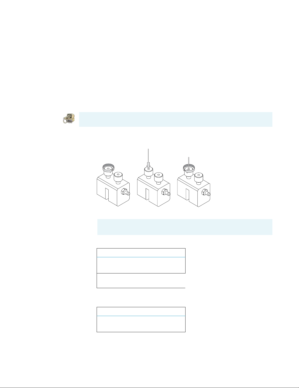
Installing a GC Column
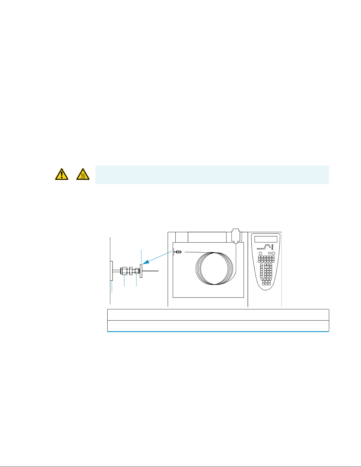
b. Carefully push the capillary column end into the flowmeter section of the
column-flow meter connector, as shown in Figure 2.
Figure 2. Flow Measure
c. Connect the flowmeter to the dedicated fitting on the column flow meter connector.
Note The available options (Right column or Left column) will differ depending
on the configuration of your GC.
d. Press Column Eval to open the following menu:
COLUMN INFORMATION
Right column
Left column <
Note Make sure the Vacuum Compensation parameter is set to OFF in the
Carrier menu, which is accessed by pressing the Left Carrier or Right Carrier
button. Otherwise an accurate column evaluation cannot be performed.
e. Scroll to the Right or Left column to evaluate and press Enter. The following menu
appears if you select the left column and and use the settings below to set the physical
characteristics of the column.
LEFT1 COLUMN INFO
Length (m) 15.00
ID (mm) 0.25
Film th. (um) 0.25
1. These settings could also apply to a right
column.
4 Ion Trap Series Hardware Manual Thermo Scientific
Page 21

1
Routine Operations
Installing a GC Column
f. Select Pre/post column? yes (Y) or no (N).
• If a pre-/post-column is not present, select N.
• If a pre-/post-column is present, select Y. You must set the length and nominal
internal diameter of the pre-/post-column in the same valid ranges for the
column. The following two lines are added to the menu.
Pre/post column? Y
P/p col. L 10.00
P/p col. ID 0.530
g. According to the physical characteristics of the column, the system calculates and
displays the relevant Column K-factor.
1
LEFT
COLUMN INFO
Column K= (0.8087)
Calc’d ID (0.0000)
Run Column eval?
1. These settings could also apply to a right
column.
h. To evaluate the column, scroll to Run column eval.? and press ENTER.
The system will set the Column K factor by pressurizing the column to obtain a
nominal carrier flow of 5 mL/min. The display shows the pressure.
i. Using the flowmeter, measure the carrier gas flow at the outlet of the column. Scroll
to Measured Flow and set the value of the flow.
EVALUATING L COLUMN
Pressure (162)
Measured Flow: 4.90
Use <STOP> to abort
Note To abort column evaluation, you can press STOP.
j. The following message will display if the operation was successful.
L. COL. EVALUATION
COMPLETED
Calc’d ID 0.242
K. 0.9020
Thermo Scientific Ion Trap Series Hardware Manual 5
Page 22
1
Routine Operations
Installing a GC Column
k. Expect a K-factor of about 0.7 – 0.9 for a 15 m, 0.25 mm i.d. column (1.3 – 2.0 for
a 30 m, 0.25 mm i.d. column). If the column does not report a K-factor within this
range or within 0.1 units of the previous stored value, check for a leak or broken
column using the leak detector. The K-factor is a measured resistance for the column.
A K-factor that is too low may indicate a leak in the system, while a K-factor that is
too high may indicate a blockage.
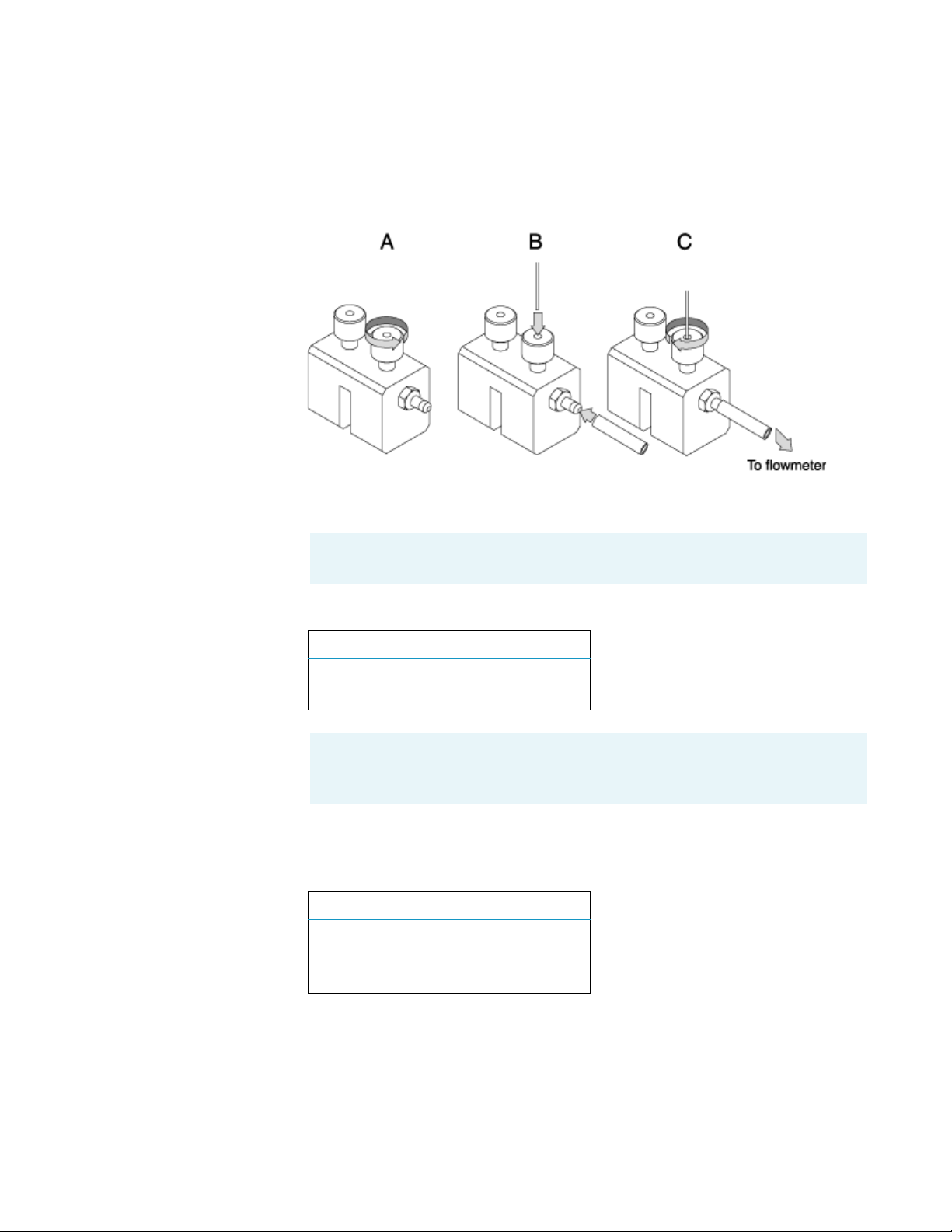
4. Perform a column leak check.
a. Carefully push the capillary column end into the column section of the column-flow
meter connector, as shown in Figure 3.
CAUTION - INSTRUMENT DAMAGE. Do not allow the clear plastic component to
exceed 80 °C. Otherwise, it will melt and damage the instrument.
Figure 3. Leak Check
A B C
b. Press Leak Check to access the Leak Check Columns menu.
Note The available options (Right column or Left column) will differ depending
on the configuration of your GC.
LEAK CHECK COLUMN
Right column
Left column <
1. This item appears if the relevant channel is
present and configured.
c. Scroll to a channel to open the left or right column’s leak check menu.
L. COL. LEAK CHECK
Start Leak Check
Leak Check Settings
6 Ion Trap Series Hardware Manual Thermo Scientific
Page 23

1
Routine Operations
Installing a GC Column
d. Scroll to Leak Check Settings.
L. COL. SETT.
Check Leak press 200
Sensitivity 5.0
e. In the Check at press line, set the pressure at which the leak check will be performed.
The value must be between 10 and 999 kPa (1.45 and 145 psi).
f. In the Sensitivity line, set the maximum pressure drop that is allowed during the test.
The value must be between 1 and 10 kPa (0.145 and 1.45 psi).
g. Press CLEAR to exit the Leak Check Settings menu and return to the previous menu.
L. COL. LEAK CHECK
Start leak check
Leak Check settings
h. Select Start leak check to begin operation. The split and purge valves of the selected
channel are automatically closed and the channel is pressurized with carrier gas to the
leak check set point.
CHECKING L COLUMN
Pressure (200)
Elapsed time 0.90
Use <STOP> to abort
Note To abort a leak check, you can press STOP.
i. The system monitors the pressure for one minute. If the pressure does not drop more
than the maximum allowed sensitivity value, then the leak check will pass.
R/L.LEAK CHECK
COMPLETED
SUCCESSFULLY
Leak check passed.
If the leak check did not pass, you should use the leak detector to find and fix the
leaks.
Tip Leaks can be caused by not tightening the fitting on the clear plastic
component. We recommend that you check that fitting before looking elsewhere.
j. Repeat the column evaluation and leak check until no leaks are indicated.
Thermo Scientific Ion Trap Series Hardware Manual 7
Page 24
1
Routine Operations
Installing a GC Column
5. Disconnect the column from the clear plastic component.
6. Remove the clear plastic component, including its fittings, from the oven and set it aside.
7. Condition the column before inserting it into the mass spectrometer.
CAUTION INSTRUMENT DAMAGE. The material released from the column during the
conditioning (column bleed) will contaminate the ion source if the column is inserted
into the transfer line. The ion source must then be cleaned.
a. Raise the injector temperature to the desired temperature (normally 250 °C).
b. Run the slow temperature program that is recommended by the manufacturer. For
example, hold the column at 40 °C for 15 minutes, then ramp it to 10 °C per minute
up to 10 °C above the maximum temperature at which you will operate the column
(normally 300+10 °C = 310 °C). Hold the column at this temperature for two hours.
CAUTION INSTRUMENT DAMAGE. Never exceed the column manufacturer’s maximum
operating temperature.
8. Connect the column to the transfer line.
a. Shut down and vent the mass spectrometer, as described in “Shutting Down” on
page 16.
b. Lower the oven temperature to 40 °C and allow it to cool before continuing.
WARNING - BURN HAZARD. The injector, oven, and transfer line may be hot. Allow
them to cool to room temperature before touching them.
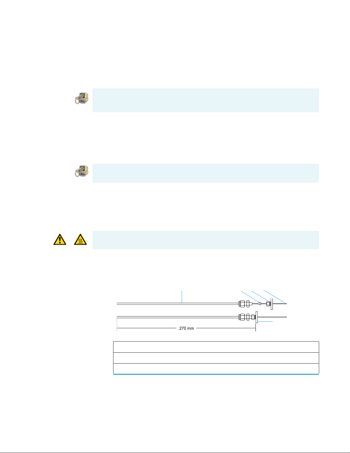
c. Unwind about one turn of the column (shown in Figure 4) from the column outlet
end.
Figure 4. Column Measuring Tool
1
3
2
4
5
1 Column Measuring Tool* 4 Column
2 Transfer Line Ferrule 5 Septum
3Transfer Line Nut
* The Column Measuring Tool is sold separately and can be purchased through
Thermo Fisher Scientific using part number 119640-0550.
8 Ion Trap Series Hardware Manual Thermo Scientific
Page 25
1
Routine Operations
Installing a GC Column
Note Wear clean, lint- and powder-free gloves when you handle the column and
transfer line ferrule.
d. Wipe about 300 mm (12 in). of the column with a tissue soaked in methanol.
e. Insert the column through the septum, transfer line nut, and ferrule. Wipe the
column again with a tissue soaked in methanol.
Note Sliding a septum on the column before the transfer line nut will help you
measure the proper distance between the nut and the end of the column. The
column should extend approximately 1–2 mm past the end of the transfer line.
f. Score and break the end of the column with a scoring wafer. With the magnifying
glass, check for an even, flat cut. Repeat, if necessary.
g. Insert the column into the transfer line using one of the following methods: Method
One, Method Two, or Method Three.
Method One
If you have a column measuring tool, follow these steps to insert the column:
1. Screw the transfer line nut onto the column measuring tool
1
.
2. Push the column past the end of the column measuring tool and score and break the end
of the column with a scoring wafer. With the magnifying glass, check for an even, flat cut.
Repeat if necessary.
3. Pull the column back so that it is flush with the end of the column measuring tool and
tighten the transfer line nut.
4. Slide the septum up to the back of the transfer line nut.
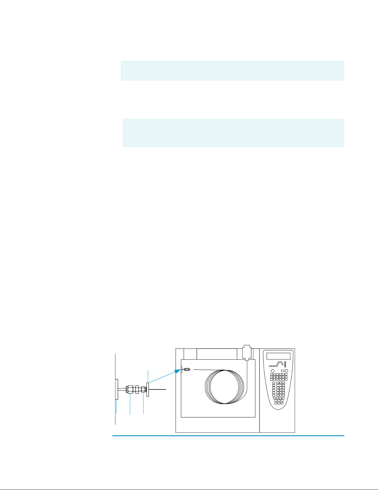
5. Remove the column, transfer line nut and ferrule from the column measuring tool, as
shown in Figure 5.
Figure 5. Transfer Line (Front)
1
2
3
4
1
Purchase the Column Measuring Tool PN 119640-0550 from Thermo Fisher Scientific.
Thermo Scientific Ion Trap Series Hardware Manual 9
Page 26

1
Routine Operations
Installing a GC Column
Figure 5. Transfer Line (Front)
1 Septum 5 Transfer Line Union
2 Transfer Line Nut 4 Transfer Line
a. Insert the column into the transfer line. Be careful not to move the septum.
b. Tighten the transfer line nut and the transfer line union.
6. Condition the transfer line ferrule. Graphite/vespel ferrules like the transfer line ferrule
require conditioning to ensure a leak-tight seal.
a. Raise the oven temperature to the maximum temperature you will operate the
column (normally 300 °C).
b. Wait 10 minutes.
c. Lower the oven temperature to 40 °C and allow it to cool before continuing.
WARNING - BURN HAZARD. The injector, oven, and transfer line may be hot. Allow
them to cool to room temperature before touching them.
Method Two
d. Re-tighten the transfer line nut and the transfer line union.
7. Set up the gas chromatograph.
a. Make sure the column does not have any sharp bends and that it does not touch any
metal objects or walls inside the oven.
b. Raise the oven temperature to the initial temperature you will use (normally 40 °C).
c. Turn on the vacuum compensation (under the right or left carrier menu).
If you have the optional inlet valve, follow these steps to insert the column:
Tip Slide a septum on the column before adding the transfer line nut to make it easier to
measure the proper distance between the nut and the end of the column. You can also use
a white marker to mark the position of the column and nut.
1. Remove the mass spectrometer front cover so you can get a better view of the column.
2. Using the I/R tool, remove the ion volume, as described in “Cleaning the Ion Source
Components” on page 37.
3. Insert the column into the transfer line and tighten the transfer line nut by hand.
4. Push the column in until you can see it through the inlet valve.
5. Pull the column back just far enough that you cannot see it.
6. Tighten the transfer line nut and transfer line union.
10 Ion Trap Series Hardware Manual Thermo Scientific
Page 27

1
Routine Operations
Installing a GC Column
7. Using the I/R tool, replace the ion volume, as described in “Cleaning the Ion Source
Components” on page 37.
8. Condition the transfer line ferrule. Graphite/vespel ferrules like the transfer line ferrule
require conditioning to ensure a leak-tight seal.
a. Raise the oven temperature to the maximum temperature you will operate the
column (normally 300 °C).
b. Wait 10 minutes.
c. Lower the oven temperature to 40 °C and allow it to cool before continuing.
WARNING - BURN HAZARD. The injector, oven, and transfer line may be hot. Allow
them to cool to room temperature before touching them.
d. Re-tighten the transfer line nut and the transfer line union.
9. Set up the gas chromatograph.
a. Make sure the column does not have any sharp bends and that it does not touch any
metal objects or walls inside the oven.
Method Three
b. Raise the oven temperature to the initial temperature you will use (normally 40 °C).
Note Turn on vacuum compensation (under the Right or Left Carrier menu).
If you do not have an inlet valve, follow these steps to insert the column:
1. Remove the front and top covers so you can get a better view of the column.
2. Remove the vacuum manifold cover, as described in “Removing the Vacuum Manifold
Cover” on page 28.
3. Remove the ion source assembly, as described in“Cleaning the Ion Source Components”
on page 37.
4. Adjust the column so that it extends 1–2 mm past the end of the transfer line.
5. Tighten the transfer line nut and transfer line union.
6. Condition the transfer line ferrule. Graphite/vespel ferrules like the transfer line ferrule
require conditioning to ensure a leak-tight seal.
a. Raise the oven temperature to the maximum temperature you will operate the
column (normally 300 °C).
b. Wait 10 minutes.
c. Lower the oven temperature to 40 °C and allow it to cool before continuing.
Thermo Scientific Ion Trap Series Hardware Manual 11
Page 28

1
Routine Operations
Installing a GC Column
WARNING - BURN HAZARD. The injector, oven, and transfer line may be hot. Allow
them to cool to room temperature before touching them.
d. Re-tighten the transfer line nut and the transfer line union.
7. Replace the ion source assembly, as described in “Cleaning the Ion Source Components”
on page 37.
8. Replace the vacuum manifold cover.
9. Replace the front and top covers.
10. Condition the transfer line ferrule. Graphite/vespel ferrules like the transfer line ferrule
require conditioning to ensure a leak-tight seal.
a. Raise the oven temperature to the maximum temperature you will operate the
column (normally 300 °C).
b. Wait 10 minutes.
c. Lower the oven temperature to 30 °C and allow it to cool before continuing.
WARNING - BURN HAZARD. The oven may be hot. Allow it to cool to room temperature
before opening it. The injector will still be hot, so do not touch it.
d. Re-tighten the transfer line nut and the transfer line union.
11. Set up the gas chromatograph.
a. Make sure the column does not have any sharp bends and that it does not touch any
metal objects or walls inside the oven.
b. Raise the oven temperature to the initial temperature you will use (normally 40 °C).
Note Turn on vacuum compensation (under the Right or Left Carrier menu).
12 Ion Trap Series Hardware Manual Thermo Scientific
Page 29
Removing a GC Column
To remove a GC column, you will need:
• Gloves, clean, lint- and powder-free
• Wrench, open-ended, 5/16-in.
• Wrench, open-ended, 7/16-in.
• Wrench, open-ended, 6 mm
1. Shut down the mass spectrometer.
a. Shut down and vent the mass spectrometer, as described in “Shutting Down” on
page 16.
b. Lower the oven, injector, and transfer line temperatures to 30 °C and allow them to
cool before continuing.
WARNING - BURN HAZARD. The injector, oven, and transfer line may be hot. Allow
them to cool to room temperature before touching them.
c. Once the oven, injector, and transfer line are cool, turn off the gas chromatograph.
1
Routine Operations
Removing a GC Column
2. Remove the column from the transfer line, as shown in Figure 6.
Figure 6. Transfer Line (Front)
1
2
3
4
1 Septum 3 Transfer Line Union
2 Transfer Line Nut 4 Transfer Line
a. Unscrew the transfer line nut.
b. Remove the column from the transfer line.
Thermo Scientific Ion Trap Series Hardware Manual 13
Page 30

1
Routine Operations
Starting Up
3. Remove the column from the injector, as shown in Figure 7.
Figure 7. Injector (Front)
6
5
1
Distance
2
3
Starting Up
4
4
1Injector 4Column
2 Injector Ferrule 5 Column Outlet
3 Injector Nut 6 Transfer Line
a. Unscrew the injector nut.
b. Remove the column from the injector.
1. Set up the mass spectrometer.
a. Install the GC column, as described in “Installing a GC Column” on page 2.
b. Verify that the gas chromatograph is on and there is carrier gas flowing through the
column into the mass spectrometer.
WARNING - INSTRUMENT DAMAGE. Damage may occur if you turn on the mass
spectrometer without column flow. This forces air to be drawn through the column. This
large air leak into the mass spectrometer may cause the ion source to require cleaning as
well as potentially damaging the column.
c. Plug in the mass spectrometer power cord.
14 Ion Trap Series Hardware Manual Thermo Scientific
Page 31

2. Turn on the mass spectrometer.
a. Switch the main circuit breaker (shown in Figure 8) to ON (I), which causes:
• The rotary-vane pump to power on
• The fore pressure to reach the proper operating pressure
• The turbomolecular pump to power on
Figure 8. Main Circuit Breaker (Rear)
1
Routine Operations
Starting Up
b. Set the transfer line to the desired operating temperature (normally 300 °C).
3. Start Xcalibur.
a. Check the heater status shown in the heater tab of the mass spectrometer status
window. If the ion source is not set to the desired temperature (normally 200 °C),
change it in Tune.
b. Check the vacuum status shown in the Vacuum tab of the mass spectrometer status
window. Within 10 minutes of powering on the detector, vacuum should read OK. If
it does not read OK, refer to “Troubleshooting” on page 123.
c. Allow the mass spectrometer to stabilize for at least 30 minutes before running
samples.
Thermo Scientific Ion Trap Series Hardware Manual 15
Page 32

1
Routine Operations
Shutting Down
Shutting Down
1. Cool the gas chromatograph.
Note If you do not plan to change the column or perform maintenance on the gas
chromatograph, you do not have to lower the injector temperature.
2. Lower the oven, injector, and transfer line temperatures to 30 °C.
3. Shut down the mass spectrometer.
a. From the Instrument Setup window, click Tune to display the Tune window.
b. Choose Instrument | Shutdown to start the automatic shutdown procedure:
• Tune Shut Down screen displays
• Calibration gas and CI reagent gas are turned off
• Voltages are turned off to the ion source, ion trap, and ion detector assembly
• Ion source heater turns off
• Turbomolecular pump turns off
• Tune waits ten minutes for the turbomolecular pump to slow down
• Tune waits for the ion source to cool to < 175
parts when they are exposed to air
4. Wait for the transfer line to cool below < 175
o
C to prevent oxidizing the hot
o
C
16 Ion Trap Series Hardware Manual Thermo Scientific
Page 33

1
Routine Operations
5. Turn off the mass spectrometer.
a. Look for a prompt indicating that it is safe to turn off the main power to the mass
spectrometer and then click OK.
b. Switch the main circuit breaker (shown in Figure 9) to OFF (0), which turns off the
rotary-vane pump. Approximately three seconds later, the vent valve opens and the
vacuum manifold vents to atmospheric pressure. This takes approximately three to
four minutes.
Figure 9. Main Circuit Breaker (Rear)
Shutting Down
c. Unplug the mass spectrometer power cord.
d. STOP HERE
if you are planning to perform system maintenance on only the mass
spectrometer (for example, to clean the ion source). You do not need to turn off the
gas chromatograph, data system and autosampler. In this case, the shutdown
procedure is complete.
6. Wait for the GC oven, injector, and transfer line to cool to room temperature.
7. Turn off all instruments.
a. Turn off the gas chromatograph using the GC main circuit breaker.
b. Turn off the GC helium supply at the tank.
c. Turn off the optional autosampler by using the main power On/Off switch.
Thermo Scientific Ion Trap Series Hardware Manual 17
Page 34

1
Routine Operations
Shutting Down
18 Ion Trap Series Hardware Manual Thermo Scientific
Page 35

Maintenance
This chapter describes how to maintain the essential components of the mass spectrometer.
Performing periodic maintenance increases laboratory productivity and helps you get the
most out of your instrument.
Contents
2
• “Main Components” on page 20
• “Recommended Maintenance Schedule” on page 21
• “Removing the Covers” on page 24
• “Removing the Vacuum Manifold Cover” on page 28
• “Assembling the Ion Source and Ion Trap” on page 30
• “Cleaning Parts” on page 32
• “Stainless Steel Parts” on page 33
• “Non-Stainless Steel or Hybrid Parts” on page 35
• “Cleaning the Ion Source Components” on page 37
• “Cleaning the Ion Trap” on page 61
• “Maintaining the Ion Detector System” on page 65
• “Maintaining a High-Vacuum Pump” on page 70
• “Maintaining a Rotary-Vane Pump” on page 71
• “Finding Components and Assemblies” on page 75
Thermo Scientific Ion Trap Series Hardware Manual 19
Page 36

2
Maintenance
Main Components
Main Components
Figure 10. Maintenance Components (Top View)
20 Ion Trap Series Hardware Manual Thermo Scientific
Page 37

Recommended Maintenance Schedule
You can perform most maintenance yourself. For your safety, be sure to read the instructions
carefully before using any procedure.
The frequency of maintenance depends on the types and amounts of sample and solvents you
use. See Ta bl e 1 for more information. To perform maintenance, you will need:
•Clean, dry gas
• Gloves, clean, lint- and powder-free
• Gloves, latex, impermeable
• Lint-free cloth or paper
• Nut driver, 5.5 mm
• Protective eyewear
• Screwdriver, Phillips #2
• Screwdriver, flat blade
• Wrench, adjustable
• Wrench, Allen, 2 mm, 2.5 mm, 3 mm, 4 mm, 5/32-in., 5/64-in., 1/16-in.
• Wrench, open-ended, 1/4-in., 5/16-in., 7/16-in. (2),
1/2-in., 9/16-in.
• Wrench, socket, 1/2-in.
2
Maintenance
Recommended Maintenance Schedule
Thermo Scientific Ion Trap Series Hardware Manual 21
Page 38

2
Maintenance
Recommended Maintenance Schedule
Ta b le 1 contains a recommended routine maintenance schedule. Time estimates are based on
running multiple samples in an 8-hour day. Adapt the schedules according to how clean your
samples are and how many analyses you plan to conduct per day. Keep a record of system
maintenance and performance to identify deviations from normal operation, which can be
used to determine how to take corrective action.
Table 1. Recommended Routine Maintenance Schedule
Item 1 Mth 4 Mth 1 Y 2 Y *As needed
Ion Source Components
“Cleaning the Ion Source Components” on page 37.
“Cleaning the Ion Volume with an Inlet Valve” on page 38.
“Cleaning the Ion Source Lenses” on page 53.
“Cleaning the Ion Source” on page 56.
“Replacing the Ion Source Filament” on page 59.
Ion Trap Components
“Cleaning the Ion Trap” on page 61.
Ion Detector System Components
“Cleaning the Ion Detector System” on page 66.
“Cleaning or Replacing the Anode” on page 67 or “Maintaining a
High-Vacuum Pump” on page 70.
Rotary Vane Pump
“Checking the Oil Level of a Rotary-Vane Pump” on page 71.
“Adding Oil to a Rotary-Vane Pump” on page 72
“Purging Gas from the Oil in a Rotary-Vane Pump” on page 73.**
Miscellaneous
“Adding Calibration Compound” on page 85.
“Replacing the Rear Cooling Fans” on page 108.
* As needed depends on how close the component is to the sample introduction point. For example, the Ion Volume is
closer to the sample introduction point than any other component and requires the most frequent cleaning.
** Perform every month if you use ammonia as a chemical ionization reagent gas.
22 Ion Trap Series Hardware Manual Thermo Scientific
Page 39

2
Maintenance
Recommended Maintenance Schedule
Figure 11 illustrates the sequence to follow when performing routine maintenance on the
mass spectrometer.
Figure 11. Sequence of Routine Maintenance (no inlet valve)
Thermo Scientific Ion Trap Series Hardware Manual 23
Page 40

2
Maintenance
Removing the Covers
Removing the Covers
Disassembling the mass spectrometer to access internal components requires removing the
necessary covers. The covers overlap each other, so you must first remove the front cover, then
the top cover, and finally the right and/or left cover. In some cases, you need only remove the
cover concealing the components you wish to service.
Removing the Front Cover
To remove the front cover:
1. Prepare the mass spectrometer for maintenance.
a. Prepare a clean work area by covering the area with lint-free cloth.
b. Shut down and vent the mass spectrometer (“Shutting Down” on page 16).
WARNING - ELECTRICAL SHOCK HAZARD. Unplug the mass spectrometer before
proceeding.
2. If your system is equipped with an inlet valve, remove the inlet valve lever by pulling it
free.
3. Grasp the cover by the left- and right-hand slots, as indicated in Figure 12. Pull the cover
toward you and it will snap out of the connectors located on the top and bottom of the
mass spectrometer.
Figure 12. Removing the Front Cover
Left-Hand Slot
Right-Hand Slot
4. Reverse these steps to reinstall the cover.
24 Ion Trap Series Hardware Manual Thermo Scientific
Page 41

Removing the Top Cover
To remove the top cover, you will need a Phillips #2 screwdriver.
1. Prepare the mass spectrometer for maintenance.
a. Prepare a clean work area by covering the area with lint-free cloth.
b. Shut down and vent the mass spectrometer (“Shutting Down” on page 16).
)
WARNING - ELECTRICAL SHOCK HAZARD. Unplug the mass spectrometer before
proceeding.
2. Remove the front cover.
3. Loosen the fastener located on the front of the mass spectrometer that attaches the top
cover to the chassis, as illustrated in Figure 13.
Figure 13. Removing the Top Cover
Top Cover Fastener
2
Maintenance
Removing the Covers
4. Slide the top cover forward about 2.5 cm (1-inch).
5. Lift the top cover up and away from the mass spectrometer.
6. Reverse these steps to reinstall the mass spectrometer top cover.
Thermo Scientific Ion Trap Series Hardware Manual 25
Page 42

2
Maintenance
Removing the Covers
Removing the Right Cover
To remove the right cover, you will need a Phillips #2 screwdriver and a 2.5 mm Allen wrench.
)
1. :Prepare the mass spectrometer for maintenance.
a. Prepare a clean work area by covering the area with lint-free cloth.
b. Shut down and vent the mass spectrometer (“Shutting Down” on page 16).
WARNING - ELECTRICAL SHOCK HAZARD. Unplug the mass spectrometer before
proceeding.
2. Remove the front and top covers.
3. Remove the capillary column, as described in“Removing a GC Column” on page 13.
4. Remove the two screws holding the top cover to the chassis (Figure 14).
Figure 14. Removing the Right Cover
Screws holding the right cover
5. Slide the cover towards the back and pull it away from the instrument.
6. Reverse these steps to reinstall the mass spectrometer right cover.
26 Ion Trap Series Hardware Manual Thermo Scientific
Page 43

Removing the Left Cover
To remove the left cover, you will need a Phillips #2 screwdriver.
1. Prepare the mass spectrometer for maintenance.
a. Prepare a clean work area by covering the area with lint-free cloth.
b. Shut down and vent the mass spectrometer (“Shutting Down” on page 16).
)
WARNING - ELECTRICAL SHOCK HAZARD. Unplug the mass spectrometer before
proceeding.
2. Remove the front and top covers.
3. Remove the single screw located at the rear of the mass spectrometer that holds the left
cover against the chassis (Figure 15).
Figure 15. Removing the Left Cover
2
Maintenance
Removing the Covers
WARN ING
HIGH VOLTAGE
AND HOT SURFACES
CAUTION
Screw holding
left cover in
place
REV
Thermo Scientific Ion Trap Series Hardware Manual 27
Page 44

2
Maintenance
Removing the Covers
4. Slide the cover toward the rear of the mass spectrometer until the tabs come to the end of
the grooved slots and then pull the cover away from the mass spectrometer.
CAUTION INSTRUMENT DAMAGE. The analog and digital PCBs are behind the left
cover, so the left cover is significantly heavier than the right cover. Also, several cables
connect the PCBs to other parts of the instrument. Do not pull the cover too far away
from the instrument or damage to cables may occur.
5. Reverse these steps to reinstall the mass spectrometer left cover.
Removing the Vacuum Manifold Cover
Located inside the vacuum manifold are the ion source, ion trap, and ion detector system. To
perform maintenance inside the vacuum manifold, you must remove the vacuum manifold
cover, ion source and ion trap assembly.
To remove the vacuum manifold cover, you will need:
•Clean, dry gas
• Gloves, clean, lint- and powder-free
• Lint-free cloth
• Screwdriver, Phillips #2
CAUTION INSTRUMENT DAMAGE. You should always put the vacuum manifold cover
back in place to prevent dust and debris from collecting in the vacuum manifold. Even
small amounts of dust on the electron multiplier and conversion dynode feedthrough can
cause excessive noise in the mass spectra.
1. Prepare the mass spectrometer for maintenance.
a. Prepare a clean work area by covering the area with lint-free cloth.
b. Shut down and vent the mass spectrometer (“Shutting Down” on page 16).
WARNING - ELECTRICAL SHOCK HAZARD. Unplug the mass spectrometer before
proceeding.
c. )Remove the front and top covers, as described in “Removing the Covers” on
page 24.
Note Completely vent the instrument to atmospheric pressure for approximately
four minutes, or the cover will be difficult to remove.
28 Ion Trap Series Hardware Manual Thermo Scientific
Page 45

d. Remove the vacuum manifold cover (Figure 16).
Figure 16. Vacuum Manifold Cover
Vacuum Manifold Cover
2
Maintenance
Removing the Covers
2. Reattach the vacuum manifold cover.
a. Check the O-ring (PN 3814-6500) for signs of wear and replace if necessary.
b. Verify that there are no particles on the O-ring. Wipe it off with a lint-free cloth, if
necessary.
c. Clean the electron multiplier and ion trap with clean, dry gas. Do not use liquids to
clean the ion detector System.
CAUTION INSTRUMENT DAMAGE. Even the smallest amount of dust or lint on the
electron multiplier, or ion trap can cause spectral noise or instrument damage.
3. Replace the vacuum manifold cover.
4. Replace the covers.
5. Restart your system.
Thermo Scientific Ion Trap Series Hardware Manual 29
Page 46

2
Maintenance
Assembling the Ion Source and Ion Trap
Assembling the Ion Source and Ion Trap
This procedure contains instructions on how to assemble and disassemble the ion source and
ion trap.
To disassemble/assemble the ion source and ion trap, you will need:
•Clean, dry gas
• Gloves, clean, lint- and powder-free
• Lint-free cloth
• Screwdriver, Phillips #2
1. Remove the ion source and ion trap assembly.
a. Shut down and vent the mass spectrometer, as described in “Shutting Down” on
page 16.
WARNING - ELECTRICAL SHOCK HAZARD. Unplug the mass spectrometer before
proceeding.
b. Remove the front and top covers, as described in“Removing the Covers” on page 24.
c. Remove the vacuum manifold cover, as described in “Removing the Vacuum
Manifold Cover” on page 28.
d. Remove the 8-pin cable from the ion source and the 3-pin lens cable. Be careful not
to pull the cable by the wires.
Note Wear clean, lint- and powder- free gloves when you handle parts inside the
vacuum manifold.
e. Use your left hand to apply pressure to the base of the magnet yoke and slide it
towards the left of the mass spectrometer. With your right hand, grasp the exit lens
mounting bracket and move it left and right as you slide the magnet yoke to the left.
2. Replace the ion source and ion trap.
30 Ion Trap Series Hardware Manual Thermo Scientific
Page 47

Figure 17. Ion Source and Ion Trap Assembly
1
5
4
2
Maintenance
Assembling the Ion Source and Ion Trap
2
3
1Helium Supply Line 43-Pin Lens Cable
2 12-Pin Cable 5 Exit and Entrance Endcap Cables
38-Pin Source Cable
a. Loosen the two thumbscrews holding the ion source and ion trap together.
b. Rotate the exit endcap so the helium supply is pointing directly to the right.
c. Place the ring electrode groove over the RF Pin and make sure the pin does not
scratch the spacers.
d. Slide the ion source into its space in the vacuum manifold by applying pressure to the
base of the magnet yoke with your left hand and sliding it towards the right of the
mass spectrometer.
e. Align the helium supply with the helium inlet on the exit endcap and the transfer line
with the ion source.
f. Tighten the two thumbscrews just enough so that the exit and entrance endcaps
cannot be easily rotated.
g. Connect the 12-pin cable to the right side of the vacuum manifold.
CAUTION INSTRUMENT DAMAGE. Overtightening the thumbscrews can cause the ion
trap spacers or the ceramic lens holders to crack when the ion source is heated. The
thumbscrews should only be tight enough to prevent the endcap electrodes from rotating.
Thermo Scientific Ion Trap Series Hardware Manual 31
Page 48

2
Maintenance
Cleaning Parts
Cleaning Parts
A large part of maintaining your mass spectrometer consists of making sure that all the
components are clean. Use the cleaning procedures listed in this section to clean stainless steel
and non-stainless steel parts. However, use caution when doing so, as some components can
be damaged by exposure to liquids.
When your mass spectrometer is clean and in good working order, perform benchmark tests
and record the results. A good benchmark test is a solution of octafluoronaphthalene (OFN)
for EI Systems or decafluorobenzophenone (DFBZ) for CI systems. Both are available from
Thermo Fisher Scientific. When the tested performance of your system decreases significantly
from your benchmark test results, clean the ion volume. If this does not restore performance,
clean the lenses.
How often you clean the mass spectrometer depends on the types and amounts of samples
and solvents you introduce into the system. In general, the closer a component is to the
sample introduction point, the more rapidly it becomes dirty. For example, you will clean the
ion volume more often than other parts. If you just want to change or clean the ion volumes
and the mass spectrometer is equipped with an inlet valve, there is no need to shut down the
system.
Many parts can be removed and disassembled by hand. Make sure you have all the tools
needed before using each procedure. You can purchase items without part numbers at a local
hardware store.
Note This section is not intended to relate strictly to the parts and components in this
chapter. These procedures can be used to clean other stainless steel, ceramic, aluminum,
and gold-plated parts within the mass spectrometer. However, use caution when doing so,
as some components can be damaged when exposed to liquids.
32 Ion Trap Series Hardware Manual Thermo Scientific
Page 49

Stainless Steel Parts
Stainless steel parts located on your mass spectrometer require special cleaning to enhance and
ensure quality performance.
To clean stainless steel parts, such as the ion volume, ion source, and lenses you will need:
• Acetone, reagent grade (or other suitable polar solvent)
• Aluminum oxide abrasive, number 600 (PN 32000-60340)
• Applicators, cotton-tipped (PN A0301-02000)
• Beaker, 450 mL
•Clean, dry gas
•De-ionized water
• Detergent (Alconox, Micro, or equivalent)
• Dremel rotary tool or equivalent (recommended)
• Foil, aluminum
•Forceps
• Gloves, clean, lint- and powder-free
• Gloves, latex, impermeable
• Glycerol, reagent grade
• Lint-free cloth
• Protective eyewear
•Tap water
• Toothbrush, soft
• Ultrasonic cleaner
2
Maintenance
Cleaning Parts
CAUTION INSTRUMENT DAMAGE. Please do NOT use this procedure to clean ceramic,
aluminum, or gold plated parts. Also, this procedure should not be used on the ion trap,
electron multiplier, conversion dynode feedthrough, or anode feedthrough.
WARNING - MATERIAL AND EYE HAZARD. Wear impermeable laboratory gloves and eye
protection when performing cleaning procedures.
1. Remove contamination from all the surfaces you are cleaning.
a. Use a slurry of number 600 aluminum oxide in glycerol and a cleaning brush or
cotton-tipped applicator. Contamination usually appears as dark or discolored areas,
but sometimes is not visible. The heaviest contamination is usually found around the
apertures, such as the electron entrance hole on an ion volume.
b. Clean each part thoroughly, even if no contamination is visible.
c. Use the wooden end of an applicator cut at an angle to clean the inside corners.
Thermo Scientific Ion Trap Series Hardware Manual 33
Page 50

2
Maintenance
Cleaning Parts
d. Use a Dremel® tool at its lowest speed with an applicator to increase cleaning
efficiency. To prevent personal injury, be sure to keep the Dremel tool away from
possible hazards, such as standing water or flammable solvents.
WARNING - BURN HAZARD. The Dremel tool uses an electric motor that may generate
sparks. These sparks can set solvents on fire. Do not use flammable solvents with the
Dremel tool.
WARNING - ELECTRICAL SHOCK HAZARD. The Dremel tools is an electrically powered
device. Do not get the Dremel tool wet. Make sure the outlet is properly grounded and in
compliance with the local electrical codes.
2. Rinse the parts with clean water. Use a clean applicator or toothbrush to remove the
aluminum oxide slurry. Do not let the slurry dry on the metal; dried aluminum oxide is
difficult to remove.
3. Sonicate the parts in a warm detergent solution.
a. Using forceps, place the parts in a beaker containing warm detergent solution.
b. Place the beaker and contents in an ultrasonic bath for five minutes.
c. Rinse the parts with tap water to remove the detergent.
4. Sonicate the parts in deionized water.
a. Using forceps, rinse the parts with deionized water.
b. Place the beaker and contents in an ultrasonic bath for five minutes.
c. If the water is cloudy after sonicating, pour off the water, add fresh water, and place
the beaker and its contents in a ultrasonic bath again for five minutes. Repeat until
the water is clear.
5. Sonicate the parts in acetone.
a. Using forceps, rinse the parts with acetone.
b. Using forceps, transfer the parts to another beaker containing fresh acetone.
c. Place the beaker and contents in an ultrasonic bath again for five minutes.
6. Using forceps remove and blow-dry the parts immediately. Use clean, dry gas to blow the
acetone off the parts.
7. Using forceps, place the parts in a clean, dry beaker, cover the beaker with aluminum foil,
and put the beaker in the GC oven.
8. Dry the parts in an oven set at 100
o
C for 30 minutes.
9. Allow the parts to cool before putting them back together.
34 Ion Trap Series Hardware Manual Thermo Scientific
Page 51

Non-Stainless Steel or Hybrid Parts
Non-stainless steel or hybrid parts also require periodic cleaning to ensure and enhance
quality performance.
CAUTION INSTRUMENT DAMAGE. Do NOT use this procedure to clean the electron
multiplier, or ion trap.
To clean non-stainless or hybrid parts, such as the lens holder and spacer, filament spacer, and
heater ring, you will need:
• Acetone, reagent grade (or other suitable polar solvent)
• Aluminum oxide abrasive, number 600 (PN 32000-60340)
• Applicators, cotton-tipped (PN A0301-02000)
• Beaker, 450 mL
•Clean, dry gas
•De-ionized water
• Detergent (Alconox, Micro, or equivalent)
• Dremel rotary tool or equivalent (recommended)
•Forceps
• Gloves, clean, lint- and powder-free
• Gloves, latex, impermeable
• Glycerol, reagent grade
• Lint-free cloth
• Protective eyewear
•Tap water
• Toothbrush, soft
2
Maintenance
Cleaning Parts
WARNING - MATERIAL AND EYE HAZARD. Wear impermeable laboratory gloves and eye
protection when performing cleaning procedures.
1. Remove contamination from stainless steel surfaces. It is only necessary to clean a surface
that comes in contact with the ion beam.
a. Use a slurry of number 600 aluminum oxide in glycerol and a cleaning brush or
cotton-tipped applicator. Contamination usually appears as dark or discolored areas,
but sometimes is not visible.
b. Clean each part thoroughly, even if no contamination is visible.
c. Use the wooden end of an applicator cut at an angle to clean the inside corners.
d. Use a Dremel tool at its lowest speed with an applicator to increase cleaning
efficiency. To prevent personal injury, be sure to keep the tool away from possible
hazards, such as standing water or flammable solvents.
WARNING - BURN HAZARD. The Dremel tool uses an electric motor that may generate
sparks. These sparks can set solvents on fire. Do not use flammable solvents with the
Dremel tool.
Thermo Scientific Ion Trap Series Hardware Manual 35
Page 52

2
Maintenance
Cleaning Parts
WARNING - ELECTRICAL SHOCK HAZARD. The Dremel tools is an electrically powered
device. Do not get the Dremel tool wet. Make sure the outlet is properly grounded and in
compliance with the local electrical codes.
2. Rinse the parts with clean water. Use a clean applicator or toothbrush to remove the
aluminum oxide slurry. Do not let the slurry dry on the metal; dried aluminum oxide is
difficult to remove.
3. Scrub all of the parts with a warm detergent solution.
a. Scrub the parts with a toothbrush or clean applicator. Do not soak or sonicate the
parts in detergent.
b. Using forceps, rinse the parts thoroughly with tap water to remove the detergent.
CAUTION INSTRUMENT DAMAGE. Do not leave aluminum parts, such as the heater
ring, in the detergent. Basic solutions, like detergent, discolor aluminum.
4. Rinse the parts in deionized water. Using forceps, dip the parts in a beaker of deionized
water. Change the water if it becomes cloudy. Do not soak or sonicate the parts.
5. Rinse the parts with acetone. Using forceps, dip the parts in a beaker of acetone. Change
the acetone if it becomes cloudy. Do not soak or sonicate the parts.
6. Blow-dry the parts immediately. Use clean, dry gas to blow the acetone off the parts.
36 Ion Trap Series Hardware Manual Thermo Scientific
Page 53

Cleaning the Ion Source Components
The ion source consists of an ion volume, filament, and ion source lenses. Because the ion
volume is exposed directly to samples introduced into the mass spectrometer, it requires the
most frequent cleaning. You can access the ion volume assembly with or without an inlet
valve. If cleaning the ion volume does not restore system performance then clean the ion
source lenses. If cleaning either of these components does not restore system performance, try
cleaning the entire ion source.
This section contains information about:
• “Cleaning the Ion Volume with an Inlet Valve” on page 38
• “Replacing the Inlet Valve Seal” on page 46
• “Replacing the Ball Valve Seal and O-Ring” on page 48
• “Cleaning the Ion Volume without an Inlet Valve” on page 49
• “Cleaning the Ion Source Lenses” on page 53
2
Maintenance
Cleaning the Ion Source Components
• “Cleaning the Ion Source” on page 56
• “Replacing the Ion Source Filament” on page 59
Figure 18 illustrates the ion source.
I
Figure 18. Ion Source Components (Left View)
2
5
1
6
3
1 Ion Source Lenses 4 Magnet Support
4
2 Filament Assembly 5 Magnets
3 Ion Source Block 6 Ion Volume (inside the Ion Source Block)
Thermo Scientific Ion Trap Series Hardware Manual 37
Page 54

2
Maintenance
Cleaning the Ion Source Components
Cleaning the Ion Volume with an Inlet Valve
The ion volume is where molecules interact with energetic electrons to form ions. Because the
ion volume is exposed directly to samples introduced into the mass spectrometer, you will
clean it more frequently than other parts. How often you clean the ion volume assembly will
depend on the types and amounts of samples.
Using an I/R tool allows you to access the ion volume by entering the vacuum manifold
through the inlet valve without venting the instrument.
To clean the ion volume with an inlet valve, you will need:
• Cleaning supplies for stainless steel parts
• Gloves, clean, lint- and powder-free
• Insert/Removal (I/R) Tool and Guide Bar
• Lint-free cloth
1. In Xcalibur, open the Insert/Remove Probe window.
a. From the Xcalibur home page, click mass spectrometer from the Status tab.
b. Click Insert/Remove Probe in the mass spectrometer Status tab.
Figure 19. I/R Tool and Guide Bar
2
1
12
10
9
3
4
11
5
8
7
1Alignment Line 7Guide Bar Track
6
2Lock Position 8First Stop
3Unlock Position 9Guide Bar
4 I/R Tool 10 Guide Ball Hole
5Bayonet Lock 11Guide Ball
6Second Stop 12Handle
38 Ion Trap Series Hardware Manual Thermo Scientific
Page 55

2
Cleaning the Ion Source Components
2. Prepare the inlet valve and I/R tool for insertion.
Make sure the inlet valve is closed (inlet valve lever is down, as shown in Figure 20) and
remove the inlet valve plug. The inlet valve plug prevents air from entering the vacuum
manifold in case the inlet valve is inadvertently opened.
Figure 20. Inlet Valve Components
1
2
3
Maintenance
5
4
1 Inlet Valve Knob 4 Inlet Valve Lever (down is closed,
up is open)
2 Inlet Valve Seal 5 Guide Bar Housing
3 Inlet Valve and Inlet Valve Plug
3. Turn the I/R tool to the unlock position , which indicates the I/R tool is in
position to accept the ion volume.
4. Insert the I/R tool and evacuate the inlet valve.
a. Insert the guide bar into the guide bar opening. With the guide ball track facing left,
insert the guide bar into the entry housing, which is shown in Figure 19. Push the
guide bar in as far as it will go, then rotate it 90-degrees counter-clockwise to lock the
guide bar in position.
Thermo Scientific Ion Trap Series Hardware Manual 39
Page 56

2
Maintenance
Cleaning the Ion Source Components
b. Insert the guide ball into the guide ball hole. Slide the I/R tool forward in the guide
bar track until the guide ball is at the guide bar’s first stop, which is shown in
Figure 21.
Figure 21. I/R Tool at Guide Bar First Stop
1
5
2
3
4
1 Inlet Valve Opening 4 Guide Bar
2 Guide Bar Housing 5 I/R Tool
3Second Stop
c. Turn the I/R tool so the guide ball is in the groove at the first stop. This prevents the
probe from being pulled forward when the inlet valve is evacuated.
d. Tighten the inlet valve knob to ensure a leak-tight seal.
e. In Xcalibur’s Insert/Remove Probe window, click the Evacuate Inlet Valve button.
Figure 22. Insert/Remove Probe Window
40 Ion Trap Series Hardware Manual Thermo Scientific
Page 57

Cleaning the Ion Source Components
f. Monitor the foreline pressure while evacuating the inlet valve. The pressure should
not remain beyond 350 mTorr. If this occurs, the inlet valve seal must be replaced, as
described in“To replace the inlet valve seal, you will need:” on page 46.
g. Once evacuation is complete, pull the inlet valve lever up to open the inlet valve.
5. Remove the ion volume.
a. Slide the I/R tool into the vacuum manifold until the tip of the I/R tool is fully
inserted into the ion volume holder, as shown in Figure 23. The guide ball will be
slightly beyond the second stop on the guide bar.
Figure 23. I/R Tool Inserted into the Inlet Valve
1
2
Maintenance
2
3
1 I/R Tool 3 Guide Bar
2 Inlet Valve Opening
b. Turn the I/R tool handle counterclockwise to put the I/R tool into lock
position . Listen for a click indicating the handle is fully engaged in the lock
position and is holding the ion volume.
c. Withdraw the I/R tool (the ion volume is attached) until the guide ball reaches the
first stop (see Figure 21).
Thermo Scientific Ion Trap Series Hardware Manual 41
Page 58

2
Maintenance
Cleaning the Ion Source Components
d. Close the inlet valve by pulling the lever down.
CAUTION INSTRUMENT DAMAGE. Do not withdraw the I/R tool beyond the point
where the guide ball reaches the first stop in the guide bar until the inlet valve is closed.
Otherwise, the system vents to the atmosphere, and cleaning may be required.
e. Loosen the inlet valve knob.
f. Continue withdrawing the I/R tool completely from the inlet valve by sliding the I/R
tool through the guide ball track in the guide bar.
WARNING - BURN HAZARD. The ion volume may be too hot to touch. Let it cool to
room temperature before handling it.
6. Clean the ion volume.
a. Remove the ion volume from the I/R tool. Using clean gloves, press the ion volume
forward into the tip of the I/R tool and rotate it to disconnect the bayonet pins from
the pin guides. Pull the ion volume out of the I/R tool, as illustrated in Figure 24.
Figure 24. I/R Tool Inserted into the Inlet Valve
1
2
3
4
5
1 Bayonet Pin 4 Spring Washer
2Bayonet Pin Guide 5Ion Volume
3Ion Volume Holder
b. Clean the ion volume by using the instructions in “Stainless Steel Parts” on page 33.
If you are cleaning a CI ion volume, be sure to clean out the small electron entrance
hole. Aluminum oxide can get trapped in this hole, which can adversely affect
sensitivity. Use a dental pick or old syringe needle to clean the hole.
42 Ion Trap Series Hardware Manual Thermo Scientific
Page 59

Cleaning the Ion Source Components
7. Place the clean ion volume on the I/R tool.
a. Place the ion volume into the bayonet lock located on the I/R tool. Make sure the
alignment arrows on the ion volume and I/R tool are facing each other.
Figure 25. Placing the Ion Volume on the I/R Tool
4
2
Maintenance
2
3
1
7
5
6
1 Ion Volume Alignment Arrow 5 Bayonet Guide
2 Bayonet Pin 6 I/R Tool
3Bayonet Lock 7Ion Volume
4 I/R Tool Alignment Arrow
Note Wear clean, lint- and powder- free gloves when you handle parts inside the
vacuum manifold.
b. Turn the I/R tool handle to the lock position .
CAUTION INSTRUMENT DAMAGE. The arrows on the I/R tool and ion volume must be
aligned to avoid damage to the ion source.
8. Insert the I/R tool and evacuate the inlet valve.
a. Insert the guide ball into the guide ball hole and slide the I/R tool forward in the
guide bar track until the guide ball is at the guide bar’s first stop (see Figure 21).
b. Turn the I/R tool so the guide ball is in the groove at the first stop. This prevents the
probe from being pulled forward when the inlet valve is evacuated.
c. Tighten the inlet valve knob to ensure a leak-tight seal.
d. In Xcalibur’s Insert/Remove Probe window, select Evacuate Inlet Valve.
Thermo Scientific Ion Trap Series Hardware Manual 43
Page 60

2
Maintenance
Cleaning the Ion Source Components
e. Monitor the foreline pressure while evacuating the inlet valve. The pressure should
not remain beyond 350 mTorr. If this occurs, the inlet valve seal must be replaced, as
described in “To replace the inlet valve seal, you will need:” on page 46.
f. Once evacuation is complete, pull the inlet valve lever up to open the inlet valve.
Figure 26. Ion Volume Connected to the Ion Source Block
1
2
1 Ion Source Block 2 Ion Volume
9. Reinsert the ion volume.
a. Slide the I/R tool into the vacuum manifold.
b. Listen for a click indicating that the ion volume has connected with the ion source
block. The guide ball will be slightly beyond the second stop on the guide bar.
c. Turn the I/R tool handle to the unlock position .
d. Verify that the ion volume is fully seated in the ion source block:
• Withdraw the I/R tool away from the ion volume about 2.5 cm (1 in). and turn
the I/R tool handle to the lock position.
• Slide the I/R tool back into the vacuum manifold until the end of the I/R tool
just touches the ion volume.
• If the I/R tool does not go back to the second stop on the guide bar completely,
the ion volume is seated properly.
e. Withdraw the I/R tool until the guide ball reaches the first stop.
f. Close the inlet valve by pulling the lever down.
CAUTION INSTRUMENT DAMAGE. Do not withdraw the I/R tool beyond the point
where the guide ball reaches the first stop in the guide bar until the inlet valve is closed.
Otherwise, the system vents to the atmosphere and cleaning may be required.
44 Ion Trap Series Hardware Manual Thermo Scientific
Page 61

Cleaning the Ion Source Components
g. Loosen the inlet valve knob.
h. Continue withdrawing the I/R tool completely from the inlet valve by sliding the I/R
tool through the guide ball track in the guide bar.
10. Remove the I/R tool and guide bar from the vacuum manifold.
a. Remove the guide bar by rotating it 90-degrees counter-clockwise and sliding it out
of the entry housing.
b. Replace the inlet valve plug.
c. In Xcalibur’s Insert/Remove Probe window, click the Close button.
Figure 27. Insert/Remove Probe Window
2
Maintenance
Thermo Scientific Ion Trap Series Hardware Manual 45
Page 62

2
Maintenance
Cleaning the Ion Source Components
Replacing the Inlet Valve Seal
To replace the inlet valve seal, you will need:
• Lint-free cloth
• Screwdriver, Phillips #2
• Wrench, open-ended, 5/16-in.
• Wrench, Allen, 4 mm
1. Close the inlet valve by pulling the inlet valve lever down, as shown in Figure 28.
Figure 28. Inlet Valve Seal
1
1 Inlet Valve Seal 2 Inlet Valve Lever
2
46 Ion Trap Series Hardware Manual Thermo Scientific
Page 63

Cleaning the Ion Source Components
2. Remove the inlet valve plug and knob, which are shown in Figure 29.
Figure 29. Inlet Valve Components (I/R Tool Not Shown)
2
1
10
2
Maintenance
9
8
7
6
3
4
5
1 Inlet Valve Solenoid 6 Guide Bar
2 Vacuum Manifold 7 Guide Bar Housing
3 Inlet Valve Knob 8 Inlet Valve Block
4 Inlet Valve Plug 9 Foreline Hose Connection
5 Ball Valve Lever 10 Ball Valve Housing
3. Remove the metal ferrule, which is located behind the inlet knob. Pay careful attention to
the way the ferrule is in the inlet. Do not put the ferrule on backwards.
4. Remove the existing inlet valve seal.
a. Insert the inlet valve removal tool (Figure 30) into the inlet valve.
Figure 30. Inlet Valve Seal Removal Tool (PN 119283-0001)
b. Press the button on the tool to engage the seal.
c. Pull out the seal and discard it.
Thermo Scientific Ion Trap Series Hardware Manual 47
Page 64

2
Maintenance
Cleaning the Ion Source Components
5. Replace the inlet valve seal with a new one.
CAUTION INSTRUMENT DAMAGE. Do not scratch the surface of the seal. Only use the
supplied tool when placing a new seal in the inlet valve.
6. Put the ferrule, knob and plug back into the inlet valve opening.
Replacing the Ball Valve Seal and O-Ring
To replace the ball valve seal and O-ring, you will need:
• Ball Valve, complete (PN A0101-02530)
• Inlet Valve Seal Kit (PN 119265-0003)
• Lint-free cloth
• Replacement Ball Valve O-ring and Seal Kit (PN 76461-2002)
• Screwdriver, Phillips #2
• Wrench, open-ended, 5/16-in.
• Wrench, Allen, 4 mm
1. Prepare the mass spectrometer for maintenance.
a. Prepare a clean work area by covering the area with lint-free cloth.
b. Shut down and vent the mass spectrometer, as described in “Shutting Down” on
page 16.
WARNING - ELECTRICAL SHOCK HAZARD. Unplug the mass spectrometer before
proceeding.
c. Remove the front and top covers, as described in “Removing the Covers” on page 24.
2. Remove the inlet valve.
a. Remove the inlet valve plug, knob, and ferrule (Figure 29).
b. Disconnect the foreline hose connection from the inlet valve.
c. Disconnect the inlet valve solenoid from the vacuum control PCB.
d. Remove the four hex-socket screws that hold the Inlet valve entry housing to the
vacuum manifold.
e. Remove the inlet valve from the vacuum manifold and place it on a clean surface.
48 Ion Trap Series Hardware Manual Thermo Scientific
Page 65

3. Replace the inlet valve.
a. Insert the new inlet valve into the vacuum manifold.
b. Verify that the entry housing, ball valve, and O-ring are intact. Check the O-ring for
wear and replace it if necessary.
c. Use the four hex-socket screws to reattach the entry housing to the vacuum manifold.
d. Reconnect the foreline hose connection to the inlet valve.
e. Reconnect the inlet valve solenoid to the vacuum control PCB.
4. Restore the mass spectrometer for operation.
a. Replace the covers.
b. Restart the system.
Cleaning the Ion Volume without an Inlet Valve
To clean the ion volume without an inlet valve, you will need:
• Cleaning supplies for stainless steel parts
• Gloves, clean, lint- and powder-free
• Ion Volume Tool (PN 119270-0001)
• Lint-free cloth
• Screwdriver, Phillips #2
2
Maintenance
Cleaning the Ion Source Components
The ion volume is where molecules interact with energetic electrons to form ions. Because the
ion volume is exposed directly to samples introduced into the mass spectrometer, you need to
clean it more frequently than other components. How often you clean the ion volume
depends on the types and amounts of samples you use with the mass spectrometer.
1. Prepare the mass spectrometer for maintenance.
a. Prepare a clean work area by covering the area with lint-free cloth.
b. Shut down and vent the mass spectrometer (“Shutting Down” on page 16).
WARNING - ELECTRICAL SHOCK HAZARD. Unplug the mass spectrometer before
proceeding.
c. )Remove the front and top covers, as described in “Removing the Covers” on
page 24.
d. Remove the vacuum manifold cover, as described in “Removing the Vacuum
Manifold Cover” on page 28.
Note Wear clean, lint- and powder- free gloves when you handle parts inside the
vacuum manifold.
Thermo Scientific Ion Trap Series Hardware Manual 49
Page 66

2
Maintenance
Cleaning the Ion Source Components
2. Remove the ion volume.
a. Insert the ion volume tool into the ion volume holder through the opening in the Ion
source PCB (Figure 31).
Figure 31. Removing the Ion Volume (Top View)
1
2
3
4
1 Ion Source Lenses 3 Transfer Line
2 Ion Source PCB 4 Ion Volume Holder (not shown)
b. Turn the ion volume tool handle 30° counter-clockwise to engage the ion volume
holder.
c. Use the ion volume tool to pull the ion volume straight back and through the
opening in the ion source PCB.
50 Ion Trap Series Hardware Manual Thermo Scientific
Page 67

2
Maintenance
Cleaning the Ion Source Components
3. Clean the ion volume.
a. Using clean, lint- and powder-free gloves, press the ion volume forward into the tip of
the ion volume tool and rotate it to disconnect the bayonet pin from the bayonet
guide.
b. Pull the ion volume out of the ion volume tool (Figure 32).
Figure 32. Ion Volume
2
1
4
3
6
5
1 Bayonet Pin 4 Ion Volume Holder
2Bayonet Guide 5Spring Washer
3Ion Volume Tool 6Ion Volume
c. Clean the ion volume using the instructions described in “Stainless Steel Parts” on
page 33. If you are cleaning a CI ion volume, be sure to clean out the small electron
entrance hole. Aluminum oxide can get trapped in this hole, which can adversely
affect sensitivity. Use a dental pick or old syringe needle to clean the hole.
4. Replace the ion volume.
a. Insert the ion volume holder onto the end of the ion volume tool, as shown in
Figure 33.
Thermo Scientific Ion Trap Series Hardware Manual 51
Page 68

2
Maintenance
Cleaning the Ion Source Components
Figure 33. Inserting the Ion Volume on the Ion Volume Tool
4
2
1
7
3
5
6
1 Ion Volume Alignment Arrow 5 Bayonet Guide
2 Bayonet Pin 6 Ion Volume Tool
3 Bayonet Lock 7 Ion Volume Holder
4 Ion Volume Tool Alignment Arrow
Note Wear clean, lint- and powder- free gloves when you handle parts inside the
vacuum manifold.
b. Use the ion volume tool to push the ion volume straight back through the opening in
the ion source PCB. Turn the ion volume tool handle 30° clockwise to disengage the
ion volume. Be sure the ion volume is oriented with the arrow up and that the ion
volume goes all the way into the ion source block and snaps into place.
CAUTION INSTRUMENT DAMAGE. Make sure the arrows on the ion volume tool and
ion volume are aligned to avoid damaging the ion source.
5. Restore the mass spectrometer for operation.
a. Replace the vacuum manifold cover.
b. Replace the covers.
c. Restart the system.
52 Ion Trap Series Hardware Manual Thermo Scientific
Page 69

Cleaning the Ion Source Lenses
If cleaning the ion volume did not restore system performance, try cleaning the ion source
lenses. The ion source lenses come in direct contact with samples introduced into the mass
spectrometer and need to be cleaned periodically (though not as often as the ion volume).
To clean the ion source lenses, you will need:
• Cleaning supplies for stainless steel parts
• Gloves, clean, lint- and powder-free
• Lint-free cloth
• Screwdriver, Phillips #2
1. Prepare the mass spectrometer for maintenance.
a. Prepare a clean work area by covering the area with lint-free cloth.
b. Shut down and vent the mass spectrometer (“Shutting Down” on page 16.
WARNING - ELECTRICAL SHOCK HAZARD. Unplug the mass spectrometer before
proceeding.
2
Maintenance
Cleaning the Ion Source Components
c. Remove the front and top covers, as described in “Removing the Covers” on page 24.
d. Remove the vacuum manifold cover (“Removing the Vacuum Manifold Cover” on
page 28).
Note Wear clean, lint- and powder- free gloves when you handle parts inside the
vacuum manifold.
2. Remove the ion source.
a. Remove the ion source and ion trap (“To disassemble/assemble the ion source and
ion trap, you will need:” on page 30).
b. Remove the two thumbscrews holding the ion trap and ion source together, as shown
in Figure 34.
Thermo Scientific Ion Trap Series Hardware Manual 53
Page 70

2
Maintenance
Cleaning the Ion Source Components
Figure 34. Removing the ion source and ion trap
1
3
2
6
5
4
1Magnet Yoke 4Ion Source
2Springs 5Ion Source Lenses
3 Two thumbscrews holding the Ion
6Ion Trap
Trap and Ion Source
c. Remove the magnet yoke and ion source.
d. Remove the lenses from the ceramic lens holder.
54 Ion Trap Series Hardware Manual Thermo Scientific
Page 71

Figure 35. Ion Source Assembly
2
Maintenance
Cleaning the Ion Source Components
3
2
Assembled
4
5
6
1
1Lens Holder 4Lens 1
2 Lens Spacer 5 Lens 2
3Lens Clip 6Lens 3
i. Remove the ion source lens assembly (Figure 35).
ii. Remove the lens clip by pinching the ends with your fingers or a pair of tweezers.
3. Clean the ion source lenses according to the procedure in“Stainless Steel Parts” on
page 33. Pay particular attention to the areas inside the tube and around the hole in each
lens.
4. Replace the ion source.
a. Insert the lenses and lens spacers into the ceramic lens holder.
b. Install the lens clip by pinching the ends or a pair of tweezers.
c. Insert the ion source lenses into the heater ring on the ion source.
d. Reassemble the ion source and ion trap.
e. Reinstall the ion source and ion trap into the vacuum manifold, as described in “To
disassemble/assemble the ion source and ion trap, you will need:” on page 30.
5. Restore the mass spectrometer for operations.
a. Replace the vacuum manifold cover.
b. Replace the covers.
c. Restart the system.
Thermo Scientific Ion Trap Series Hardware Manual 55
Page 72

2
Maintenance
Cleaning the Ion Source Components
Cleaning the Ion Source
If cleaning the ion volume and ion source lenses do not restore system performance, clean the
ion source.
To clean the ion source, you will need:
•Cleaning supplies
• Gloves, clean, lint- and powder-free
• Lint-free cloth
• Screwdriver, Phillips #2
1. Prepare the mass spectrometer for maintenance.
a. Prepare a clean work area by covering the area with lint-free cloth.
b. Shut down and vent the mass spectrometer (“Shutting Down” on page 16).
WARNING - ELECTRICAL SHOCK HAZARD. Unplug the mass spectrometer before
proceeding.
c. Remove the front and top covers, as described in “Removing the Covers” on page 24.
d. Remove the vacuum manifold cover, as described in “Removing the Vacuum
Manifold Cover” on page 28.
e. Remove the ion source and ion trap, which are shown below in Figure 36 and
described in “Removing the Vacuum Manifold Cover” on page 28.
Figure 36. Removing the ion source and ion trap
1
3
2
6
5
4
1Magnet Yoke 4 Ion Source
2 Two Springs 5 Ion Source Lenses
3 Two thumbscrews holding the
6Ion Trap
Ion Trap and Ion Source
56 Ion Trap Series Hardware Manual Thermo Scientific
Page 73

Cleaning the Ion Source Components
Note Wear clean, lint- and powder- free gloves when you handle parts inside the
vacuum manifold.
2. Disassemble the ion source.
a. Remove the two thumbscrews holding the ion trap and ion source together.
b. Remove the magnet yoke and the ion source.
c. Remove the ion source lenses.
d. Remove the spring thumbscrew (shown in Figure 37) from the ion source block.
Figure 37. Ion Source Block Assembly
2
Maintenance
12
13
14
1
9
8
11
10
2
5
6
7
4
1 Ceramic Spacer 8 Ion Volume Pin
2 Cartridge Heaters 9 Ion Volume
3Base-Studs 10Spring
4 Ion Source Block PCB 11 Spring Thumbscrew
5 Temperature Sensor 12 Heater Ring
3
6 Ion Source Block 13 Sample Inlet Aperture
7 Ion Volume Key Thumbscrew 14 Filament Spacer
e. Remove the three base-studs, but be careful not to damage the leads on the ion source
PCB.
f. Gently remove the ion source PCB from the ion source by sliding the three cartridge
heaters and temperature sensor off the ion source and pulling the filament straight
away from the three filament connectors on the ion source block PCB.
Thermo Scientific Ion Trap Series Hardware Manual 57
Page 74

2
Maintenance
Cleaning the Ion Source Components
CAUTION INSTRUMENT DAMAGE. Do not bend or twist the cartridge heaters or
temperature sensor.
g. Remove the filament and ceramic spacer (shown in Figure 37) from the ion source
block.
h. Remove the ion volume key thumbscrew.
Note It is not necessary to remove the ion volume pin. If you remove it, you
should reinsert it just far enough so the ball will keep an ion volume from falling
out. If the ball extends too far, the ion volume will be difficult to insert or
remove.
3. Clean and replace the ion source.
a. Clean each component, as described in “To clean stainless steel parts, such as the ion
volume, ion source, and lenses you will need:” on page 33 and “To clean
non-stainless or hybrid parts, such as the lens holder and spacer, filament spacer, and
heater ring, you will need:” on page 35.
b. Reassemble the ion source.
c. Insert the ion source and ion trap into the vacuum manifold, as described in “To
disassemble/assemble the ion source and ion trap, you will need:” on page 30.
4. Restore the mass spectrometer for operation.
a. Replace the vacuum manifold cover.
b. Replace the covers.
c. Restart the system.
58 Ion Trap Series Hardware Manual Thermo Scientific
Page 75

Replacing the Ion Source Filament
The number of ions produced in the ion source is approximately proportional to the filament
emission current. If you notice a lack in ion production, this might indicate that the filament
has failed and needs to be replaced. If the measured emission current is substantially less than
the value that the emission current is set to, or if the measured emission current is decreasing
over time, then the filament has failed or is failing and needs to be replaced.
To replace the ion source filament, you will need:
• Filament (PN 119701-60287)
• Gloves, clean, lint- and powder-free
• Lint-free cloth
• Screwdriver, Phillips #2
Figure 38. Ion Source Filament Assembly
2
Maintenance
Cleaning the Ion Source Components
2
1
3
4
1Ion Source Lenses 3Ion Source PCB
2Ion Source Filament 4Three Base Studs
1. Prepare the mass spectrometer for maintenance.
a. Prepare a clean work area by covering the area with lint-free cloth.
b. Shut down and vent the mass spectrometer system described in “Shutting Down” on
page 16.
WARNING - ELECTRICAL SHOCK HAZARD. Unplug the mass spectrometer before
proceeding.
c. Remove the front, and top covers as described in “Removing the Covers” on page 24.
d. Remove the vacuum manifold cover.
e. Remove the ion source and ion trap.
Note Wear clean, lint- and powder- free gloves when you handle parts inside the
vacuum manifold.
Thermo Scientific Ion Trap Series Hardware Manual 59
Page 76

2
Maintenance
Cleaning the Ion Source Components
2. Disassemble the ion source and ion trap.
a. Remove the ion source lenses.
b. Remove the three base-studs.
c. Remove the filament assembly and ion source block from the three filament
connectors and cartridge heaters on the ion source PCB.
CAUTION INSTRUMENT DAMAGE. Do not bend or twist the cartridge heaters or
temperature sensor.
Note Now is a good time to clean the ion volume and ion source lenses.
3. Inspect and install a new filament assembly.
a. Verify that the filament wire is centered in the electron lens hole. See Figure 39 for a
view of a centered wire.
Figure 39. Ion Source Filament
Centered Wire
b. Insert the filament into the spacer of the ion source block.
c. Align the filament leads with the ion source PCB connectors and gently press the
leads into the connectors. Normally, there is a small gap about 0.5 mm (0.020 in).
between the filament and the connectors. The gap allows the ceramic filament
centering ring to properly position and align the electron lens hole with the ion
volume.
d. Reinstall the three base-studs.
4. Reassemble and reinstall the ion source and ion trap.
a. Reassemble the ion source.
b. Insert the ion source and ion trap into the vacuum manifold.
5. Restore the mass spectrometer for operation.
a. Replace the vacuum manifold cover.
b. Replace the covers.
c. Restart the system.
60 Ion Trap Series Hardware Manual Thermo Scientific
Page 77

Cleaning the Ion Trap
An ion trap (also known as the mass analyzer) is an assembly composed of an entrance endcap,
ring, and exit endcap. The ions that enter the ion trap are created in an external ionization
source and are transferred into the ion trap through three lenses, and are separated according
to mass-to-charge (m/z)ratios. Figure 40 shows a detailed view of the ion trap.
Figure 40. Ion Trap (Top View)
2
Maintenance
Cleaning the Ion Trap
1
7
6
5
2
3
4
1Exit Endcap 5Ring
2 Exit Lens Spacer 6 Entrance Endcap
3Exit Lens 7Electrode Spacers
4Helium Inlet
A clean, dust-free ion trap is essential for good quality spectra. The ion trap requires less
cleaning than the ion volume and the ion source lenses. Cleaning frequency depends on the
type and quantity of the compounds that you analyze. With normal use, you do not have to
clean the ion trap more than once every two years.
Thermo Scientific Ion Trap Series Hardware Manual 61
Page 78

2
Maintenance
Cleaning the Ion Trap
To clean the ion trap, you will need:
• Acetone, reagent grade
• Beaker, 450 mL
•Clean, dry gas
• Gloves, clean, lint- and powder-free
• Gloves, latex, impermeable
• Lint-free cloth
• Protective eyewear
• Screwdriver, Phillips #2
• Ultrasonic cleaner
1. Prepare the mass spectrometer for maintenance.
a. Prepare a clean work area by covering the area with lint-free cloth.
b. Shut down and vent the mass spectrometer system described in “Shutting Down” on
page 16.
WARNING - ELECTRICAL SHOCK HAZARD. Unplug the mass spectrometer before
proceeding.
c. Remove the front cover, top cover, and vacuum manifold cover, as described in
“Removing the Covers” on page 24.
d. Remove the ion source and ion trap.
Note Wear clean, lint- and powder- free gloves when you handle parts inside the
vacuum manifold.
62 Ion Trap Series Hardware Manual Thermo Scientific
Page 79

2. Disassemble the ion source (Figure 41).
Figure 41. Removing the ion source and ion trap
7
6
2
Maintenance
Cleaning the Ion Trap
1
2
3
5
4
1Magnet Yoke 5Ion Source Lenses
2 Two Springs 6 Helium Inlet
3 Two thumbscrews holding the Ion
7Ion Trap
Trap and Ion Source
4Ion Source
a. Remove the two thumbscrews holding the ion trap and ion source together.
b. Remove the magnet yoke, ion source, and ion source lenses.
3. Disassemble the ion trap, as shown in Figure 40, by removing each component and
placing it on the lint-free cloth.
a. Remove the entrance endcap.
b. Remove the two spacers and the ring.
c. Remove the exit endcap.
4. Clean the ion trap components.
a. Place the components in a beaker and cover them with
a
acetone.
b. Place the beaker in an ultrasonic bath for about 10
minutes.
c. Pour the acetone out of the beaker.
d. Rinse the components with fresh acetone.
Thermo Scientific Ion Trap Series Hardware Manual 63
Page 80

2
Maintenance
Cleaning the Ion Trap
CAUTION INSTRUMENT DAMAGE. Do not clean the inside
e
surfaces of the ion trap with aluminum oxide. This could
damage the inside surfaces. However, if a black ion burn has
formed around the ion entrance hole in the entrance endcap
electrode, remove it using the procedure “Stainless Steel Parts”
on page 33.
e. Remove the components from the beaker. Use clean, dry
gas to blow the acetone off the components.
f. Dry the components in the GC oven set at 100 °C for 30
minutes. Allow the components to cool before
reassembling.
WARNING - BURN HAZARD. Allow the components to cool
f
before reassembling.
5. Reassemble the ion source and ion trap.
a. Reattach the exit lens spacer so that it lays flat against the
exit lens. Be careful not to put it on backwards.
b. Reattach the entrance and exit endcaps, spacers and ring. The helium inlet should be
oriented to the right.
CAUTION INSTRUMENT DAMAGE. Handle the spacers carefully and do not scrape them
against any metal surfaces. If you do, you can use acid to remove the metal deposits.
Note Use clean, dry gas to remove all dust from the ion tap. Dust, especially on
the inside of the ion trap, will cause spectral noise.
c. Reattach the ion source lenses and ion source.
d. Reattach the magnet yoke and secure it with the two thumbscrews.
6. Insert the ion source and ion trap into the vacuum manifold, as described in “To
disassemble/assemble the ion source and ion trap, you will need:” on page 30.
7. Restore the mass spectrometer for operation.
a. Replace the vacuum manifold cover.
b. Replace the covers.
c. Restart the system.
64 Ion Trap Series Hardware Manual Thermo Scientific
Page 81

Maintaining the Ion Detector System
The ion detector system consists of a conversion dynode feedthrough, and an electron
multiplier. This system must be kept clean and free of dust. Even the smallest amount of lint
on the electron multiplier can cause spectral noise or static discharge, which could lead to
power supply failure. This section describes how to replace the electron multiplier, clean the
ion detector system, and clean or replace the anode.
Replacing the Electron Multiplier
To replace the electron multiplier, you will need:
• Electron Multiplier (PN A0022-14633)
• Gloves, clean, lint- and powder-free
• Screwdriver, Phillips #2
1. Prepare the mass spectrometer for maintenance.
a. Prepare a clean work area by covering the area with lint-free cloth.
2
Maintenance
Maintaining the Ion Detector System
b. Shut down and vent the mass spectrometer (“Shutting Down” on page 16).
WARNING - ELECTRICAL SHOCK HAZARD. Unplug the mass spectrometer before
proceeding.
c. Remove the front and top covers as described in “Removing the Covers” on page 24.
d. Remove the vacuum manifold cover.
Note Wear clean, lint- and powder- free gloves when you handle parts inside the vacuum
manifold.
2. Remove old electron multiplier
a. Press spring tables on right side of multiplier
b. Pull up on right side of electron multiplier
c. Slide electron multiplier out of the clip on the left side
3. Install new electron multiplier
a. Slide electron multiplier into the clip on the left side
Thermo Scientific Ion Trap Series Hardware Manual 65
Page 82

2
Maintenance
Maintaining the Ion Detector System
b. Push down on right side of electron multiplier until it is fully seated.
Figure 42. Electron Multiplier Assembly
1
2
3
1 Electron Multiplier 3 Button-head screws
2Spring clip
4. Reinstall the ion source and ion trap.
5. Restore the mass spectrometer for operation.
a. Replace the vacuum manifold cover.
b. Replace the covers.
c. Restart the system.
Cleaning the Ion Detector System
To cl ea n the ion detector system, you will need:
•Clean, dry gas
• Gloves, clean, lint- and powder-free
• Screwdriver, Phillips #2
• Wrench, Allen, 2 mm
1. Prepare the mass spectrometer for maintenance.
a. Prepare a clean work area by covering the area with lint-free cloth.
b. Shut down and vent the mass spectrometer (“Shutting Down” on page 16).
WARNING - ELECTRICAL SHOCK HAZARD. Unplug the mass spectrometer before
proceeding.
c. Remove the front and top covers as described in “Removing the Covers” on page 24.
d. Remove the vacuum manifold cover.
66 Ion Trap Series Hardware Manual Thermo Scientific
Page 83

e. Remove the ion source and ion trap.
Note Wear clean, lint- and powder- free gloves when you handle parts inside the
vacuum manifold.
2. Spray the ion detector system with clean dry gas. This should remove any dust or particles
on the surface.
3. Reinstall the ion source and ion trap.
4. Restore the mass spectrometer for operation.
a. Replace the vacuum manifold cover.
b. Replace the covers.
c. Restart the system.
Cleaning or Replacing the Anode
2
Maintenance
Maintaining the Ion Detector System
To clean or replace the anode, which is located on the left side of the vacuum manifold under
the electron multiplier, you will need:
• Anode (PN 120252-0001)
• Gloves, clean, lint- and powder-free
• Lint-free cloth
• Screwdriver, Phillips #1
• Screwdriver, Phillips #2
• Wrench, Allen, 3 mm
• Wrench, open-ended, 17 mm
• Wrench, open-ended, 9/16-in.
1. Prepare the mass spectrometer for maintenance.
a. Prepare a clean work area by covering the area with lint-free cloth.
b. Shut down and vent the mass spectrometer (“Shutting Down” on page 16).
WARNING - ELECTRICAL SHOCK HAZARD. Unplug the mass spectrometer before
proceeding.
c. )Remove the front, top, and left covers as described in “Removing the Covers” on
page 24.
Thermo Scientific Ion Trap Series Hardware Manual 67
Page 84

2
Maintenance
Maintaining the Ion Detector System
2. Remove the electrometer PCB from the vacuum manifold, which is shown in Figure 43.
Figure 43. Electrometer PCB with Cover Attached (Left Side)
1
3
4
2
1
1 Two Hex-Socket screws holding
3Electrometer PCB Cover
the Electrometer PCB Cover
2Electrometer PCB Cable
Connector
4 Two nuts holding the Electrometer
PCB Connector
a. Disconnect the electrometer PCB cable.
b. Remove the two nuts and two hex-socket screws holding the electrometer PCB cover
in place (Figure 43) and then remove the cover.
c. Remove the screw holding the electrometer PCB wire to the anode feedthrough,
which is shown in Figure 44.
68 Ion Trap Series Hardware Manual Thermo Scientific
Page 85

Figure 44. Electrometer PCB with Cover Removed (Left Side)
1
2
3
4
2
Maintenance
Maintaining the Ion Detector System
1 Electrometer PCB 3 Nut holding the Electrometer
PCB to the Anode Feedthrough
2 Screw holding the Electrometer
4 Anode Feedthrough
PCB Wire to the Anode
Feedthrough
d. Remove the nut holding the electrometer PCB to the anode feedthrough.
3. Remove the anode feedthrough by unscrewing it from the vacuum manifold.
Note Wear clean, lint- and powder- free gloves when you handle parts inside the
vacuum manifold.
4. Attach the new anode feedthrough by screwing it into the vacuum manifold.
5. Reattach the electrometer PCB to the vacuum manifold.
a. Use the nut to reattach the electrometer PCB to the anode feedthrough.
b. Use the screw to reattach the electrometer PCB wire to the anode feedthrough.
c. Use the two nuts and two screws to reattach the electrometer PCB cover to the
vacuum manifold.
d. Reconnect the electrometer PCB cable.
6. Restore the mass spectrometer for operation.
a. Replace the vacuum manifold cover.
b. Replace the covers.
c. Restart the system.
Thermo Scientific Ion Trap Series Hardware Manual 69
Page 86

2
Maintenance
Maintaining a High-Vacuum Pump
Maintaining a High-Vacuum Pump
The high-vacuum pump is located directly under the vacuum manifold. It provides the high
vacuum that is necessary for ion detection. There are two types of high-vacuum pumps
available for the Ion Trap Series—a 250 L/s or a 70 L/s turbomolecular pump. Each contains
a lifetime supply of lubricant for the bearings. Figure 45 illustrates a 250 L/s turbomolecular
pump. The turbomolecular pump requires no maintenance.
Figure 45. 250 L/s Turbomolecular Pump (Left Side View)
1
2
1 Backing Port (Outlet Flange) 2 Electrical Supply Connector
Figure 46 illustrates a 70 L/s Turbomolecular Pump.
Figure 46. 70 L/s Turbomolecular Pump
1
2
1 Electric Supply Connector 2 Backing Port (Outlet Flange)
70 Ion Trap Series Hardware Manual Thermo Scientific
Page 87

Maintaining a Rotary-Vane Pump
The rotary-vane pump is located under the mass spectrometer work table. All that is required
to maintain the rotary-vane pump is to inspect, add, purge, and change the oil.
Checking the Oil Level of a Rotary-Vane Pump
Rotary-vane pump oil (PN A0301-15101) is a translucent light amber color and it should be
checked often. During normal operation, oil must always be visible in the oil level sight glass
between the MIN and MAX marks. If the oil level is below the MIN mark, add oil. If the oil
is cloudy or discolored, purge the oil to decontaminate dissolved solvents. If the pump oil is
still discolored, change it. You should change the pump oil every 3,000
months) of operation.
This section describes how “To add oil to the rotary-vane pump” on page 72, “Purging Gas
from the Oil in a Rotary-Vane Pump” on page 73, and “Changing the Oil in a Rotary-Vane
Pump” on page 73.
2
Maintenance
Maintaining a Rotary-Vane Pump
1
hours (about four
Figure 47. Rotary Vane Pump
1
2
3
11
3
4
5
6
7
8
9
10
13
14
12
1 Foreline Vacuum Hose 8 MAX Mark
2 Electrical Inlet Connector 9 Oil Drain Plug
3 Voltage Indicator 10 MIN Mark
4 Inlet Port 11 Oil Level Sight Glass
5 Gas Ballast Control 12 Mode Selector
6 Oil Filler Plugs 13 On/Off Switch
7 Outlet Port 14 Lifting Handle
1
Every 1,000 hours if using ammonia as a reagent gas for CI.
Thermo Scientific Ion Trap Series Hardware Manual 71
Page 88

2
Maintenance
Maintaining a Rotary-Vane Pump
Note During normal operation, the mode selector switch is set to high-vacuum mode
(turned fully clockwise) and the gas-ballast control is closed (0).
Adding Oil to a Rotary-Vane Pump
To add oil to the rotary-vane pump
Tools Needed
• Rotary-Vane Pump Oil (PN A0301-15101)
Frequency
As needed when the oil level is below the MIN mark on the oil
level sight glass.
Note The pump oil level must be between the MIN and MAX marks on the oil level sight
glass for the pump to operate properly.
Check the oil level by looking at the oil level sight glass (Figure 47). If the oil level is low, add
more oil using this procedure.
1. Shut down and vent the mass spectrometer system described in “Shutting Down” on
page 16.
WARNING - ELECTRICAL SHOCK HAZARD. Shut down and unplug the mass
spectrometer and rotary-vane pump before adding oil.
2. Remove one of the oil filler plugs from the rotary-vane pump.
WARNING - BURN HAZARD. Use only factory-approved rotary-vane pump oil. Using
unapproved rotary-vane pump oil may result in a fire or explosion.
3. Add fresh oil to the reservoir until the oil is half way between the MIN and MAX level
marks. If the oil level goes above the MAX level mark, remove the drain plug and drain
the excess oil into a suitable container.
4. Insert the oil filler plug back into the rotary-vane pump.
5. Plug in the rotary-vane pump and mass spectrometer.
6. Restart the system.
72 Ion Trap Series Hardware Manual Thermo Scientific
Page 89

Purging Gas from the Oil in a Rotary-Vane Pump
When the rotary-vane pump oil becomes cloudy or discolored, it is time to purge the oil.
Purging (or decontaminating) the oil removes dissolved gases and low boiling-point liquids.
You can purge the oil without interrupting system operation, but do not purge it during an
acquisition or while the electron multiplier or filament is powered on the system.
1. Set the gas ballast control to low flow (I).
2. Operate the pump for 10 minutes or until the oil is clear. If the oil remains cloudy or
discolored after 10 minutes, replace the oil.
3. Set the gas ballast control to closed (O), as shown in Figure 48.
Figure 48. Gas Ballast Control Positions
1
2
2
Maintenance
Maintaining a Rotary-Vane Pump
1 High Flow (Position II) 3 Closed (Position O)
2 Low Flow (Position I)
Changing the Oil in a Rotary-Vane Pump
You should change the rotary-vane pump oil every four months (about 3,000 hours of
operation). If you use ammonia as a chemical ionization reagent gas, change the oil every
month. Ammonia is highly basic and can damage seals in the rotary-vane pump. Purging the
oil with the gas ballast control can remove dissolved ammonia from the oil.
To change the rotary-vane pump oil:
Note For best results, change the oil while the rotary-vane pump is still warm after
operation. Be careful, however, as the oil can still be very hot at this time.
1. Shut down and vent the mass spectrometer system described in “Shutting Down” on
page 16.
3
WARNING - ELECTRICAL SHOCK HAZARD. Shut down and unplug the mass
spectrometer and rotary-vane pump before adding oil.
Thermo Scientific Ion Trap Series Hardware Manual 73
Page 90

2
Maintenance
Maintaining a Rotary-Vane Pump
2. Disassemble the rotary-vane pump.
a. Disconnect the foreline vacuum hose.
Figure 49. Rotary-Vane Pump
1
2
3
13
14
3
4
5
6
7
12
11
8
9
10
1 Foreline Vacuum Hose 8 MAX Mark
2 Electrical Inlet Connector 9 Oil Drain Plug
3 Voltage Indicator 10 MIN Mark
4Inlet Port 11Oil Level Sight Glass
5 Gas Ballast Control 12 Mode Selector
6 Oil Filler Plugs 13 On/Off Switch
7Outlet Port 14Lifting Handle
b. Place the rotary-vane pump on a bench.
WARNING - LIFTING HAZARD. To prevent injury use a proper lifting technique or
precaution to lift the rotary-vane pump. It weighs approximately 50 pounds (~23 kg).
c. Drain the spent oil.
i. Remove one of the oil filler plugs.
ii. Remove the oil drain plug and allow the oil to drain into a suitable container.
iii. Dispose of the spent oil according to local environmental regulations.
iv. Replace the oil drain plug.
74 Ion Trap Series Hardware Manual Thermo Scientific
Page 91

3. Add fresh oil.
a. Add fresh oil to the reservoir until the oil is half way between the MIN and MAX
level marks.
b. If the oil level goes above the MAX level mark, remove the drain plug and drain the
excess oil from the pump.
4. Reassemble the rotary-vane pump.
a. Replace the oil filler plug.
b. Return the rotary-vane pump to the floor.
c. Reconnect the foreline vacuum hose to the rotary-vane pump.
d. Plug in the rotary-vane pump and the mass spectrometer.
e. Restart the system.
Finding Components and Assemblies
2
Maintenance
Finding Components and Assemblies
Components and assemblies are located in four sections, the front cover, the left cover, the
right cover, and behind the mass spectrometer.
Note Keep the mass spectrometer packing materials in case defective parts must be
returned to Thermo Fisher Scientific.
CAUTION INSTRUMENT DAMAGE. Only use fuses specified in Tab l e 2 . Never replace a
fuse with a fuse of a different type, voltage, or current rating. Fuses protect circuits by
opening the circuits when an over-current occurs.
Table 2. Components and Current Ratings
Component Fuse Circuit Type/Voltage/Current Rating Part Number
Analog PCB F1 Ion Source Heater 2 A, very fast microfuse, 125 V 76339-0008
HV Regulator PCB F1, F2 Transformer Secondary 0.315 A, 5 x 20 mm, 250 V A0006-04550
HV Regulator PCB F3 Transformer Primary 800 mA, 5 x 20 mm, 250 V A0006-06075
Power Module F1, F2 In-line fuses +5 V, +36 V 3.15 A, SB, 5 x 20 mm, 250 V A0006-10510
RF Generator PCB F1 36 V 0.5 A, Quick Act, 5 x 20 mm, 250 V A0006-07608
RF Generator PCB F2 28 V 1.0 A, Quick Act, 5 x 20 mm, 250 V A0006-07610
Replace a fuse only when indicated by the Tune Diagnostics, Thermo Fisher Scientific
Technical Support, or a Thermo Fisher Scientific Customer Service Engineer.
CAUTION INSTRUMENT DAMAGE. Avoid damaging the PCBs with electrostatic
discharge by attaching a properly grounded electrostatic discharge (ESD) strap to your
wrist before replacing fuses.
Thermo Scientific Ion Trap Series Hardware Manual 75
Page 92

2
Maintenance
Finding Components and Assemblies
Ta b le 3 lists the replaceable parts (in alphabetical order) that do not require a routine
maintenance schedule and may be replaced as needed.
1
Table 3. Replaceable Parts List
Replaceable Parts
“Replacing the Analog PCB” on page 79.
“Balun PCB” on page 82.
“Replacing the Calibration Gas Flow Module” on page 83.
“Replacing the CI Reagent Gas Flow Module” on page 87.
“Replacing the Conversion Dynode/Electron Multiplier Power Supply” on page 88.
“Replacing the Convectron Gauge and Foreline Adapter” on page 90.
“Replacing the Digital PCB” on page 92.
“Replacing the Electrometer PCB” on page 93.
“Replacing the Variable Damping Gas Regulator” on page 95
“Replacing the Damping Gas Flow Module” on page 97
“Replacing the Ion Gauge” on page 99.
“Replacing the Lens Interface PCB” on page 101.
“Replacing the Low Pass Filter PCB” on page 102.
“Replacing the Power Module” on page 106.
“Replacing the Rear Cooling Fans” on page 108.
“Replacing the RF Detector PCB” on page 111.
“Replacing the RF Generator PCB” on page 113.
“Replacing the Transfer Line” on page 115
“Replacing the Turbomolecular Pump Power Supply” on page 117
“Replacing the Vacuum Control PCB” on page 119
“Replacing the Vent Valve Solenoid” on page 120
1
As needed means you should only replace the part when instructed by Tune Diagnostics, Thermo Fisher Scientific
Technical Support or a Thermo Fisher Scientific Customer Service Engineer.
76 Ion Trap Series Hardware Manual Thermo Scientific
Page 93

Figure 50. Replaceable Parts under the Top Cover
1
2
Maintenance
Finding Components and Assemblies
1
2
3
4
5
1CI Reagent Gas Flow Module 4Ion Gauge
2 Power Module 5 Vent Valve Solenoid
3 Calibration Gas Flow Module
Figure 51. Replaceable Parts behind the Left Cover
2
6
7
3
4
5
1 CI Reagent Gas Flow Module 5 Balun PCB
2 Calibration Gas Flow Module 6 RF Generator PCB
3 RF Detector PCB (covered) 7 Conversion Dynode and Electron Multiplier
Power Supply
4 Low Pass Filter PCB (covered)
Thermo Scientific Ion Trap Series Hardware Manual 77
Page 94

2
2
Maintenance
Finding Components and Assemblies
Figure 52. Replaceable Parts on the Left Cover
2
1
1 Digital PCB 2 Analog PCB
Figure 53. Replaceable Parts behind the Right Cover
1
6
1 Lens Interface PCB 4 High-Vacuum Pump
3
4
5
2 Transfer Line 5 Convectron Gauge and Foreline Adapter
3 Damping Gas Flow Module 6 Turbo Pump Power Supply
78 Ion Trap Series Hardware Manual Thermo Scientific
Page 95

Figure 54. Replaceable Parts behind the Front Cover
2
2
Maintenance
Replacing the Analog PCB
1 Turbomolecular Pump Power Supply
Replacing the Analog PCB
To replace the analog PCB, you will need:
• Analog PCB (PN 119590-0021)
• Nut driver, 5.5 mm
• Screwdriver, Phillips #2
1. Prepare the mass spectrometer for maintenance.
a. Prepare a clean work area by covering the area with lint-free cloth.
b. Shut down and vent the mass spectrometer (“Shutting Down” on page 16).
WARNING - ELECTRICAL SHOCK HAZARD. Unplug the mass spectrometer before
proceeding.
c. Remove the front, top and left side covers as described in “Removing the Covers” on
page 24.
1
2. Remove the analog PCB.
a. To get access to the analog PCB, you must remove the digital PCB. The removal
process is described in “Replacing the Digital PCB” on page 92.
b. Disconnect the remaining cables from the analog PCB.
Thermo Scientific Ion Trap Series Hardware Manual 79
Page 96

2
5
Maintenance
Replacing the Analog PCB
c. Remove the six nuts holding the analog PCB to the left side cover, as shown in
Figure 55.
d. Remove the analog PCB and set it aside.
Figure 55. Analog PCB (Left Side Panel, Top Down View)
12
12
12
1
14
2
6
12
13
FRONT
9
8
7
4
10
12
11
3
12
1 Digital PCB 8 Electron Multiplier/Conversion Dynode
Power Supply Cable Connector
2RF Control PCB Cable
9 RF Generator PCB Cable Connector
Connector
Connector
4Balun PCB Cable
3Balun PCB Cable
10 Power Module Cable Connector
11 Vacuum Control PCB Cable Connector
Connector
5GC Start Cable
Connector
6 Lens Interface PCB
12 Six nuts holding the Analog PCB to the left
cover
13 Fuse
Cable Connector
7CI Reagent Gas Flow
14 Digital PCB Cable Connector
Module Cable Connector
80 Ion Trap Series Hardware Manual Thermo Scientific
Page 97

3. Replace the analog PCB.
a. Position the new analog PCB so that the six nuts will fit through the board.
b. Use four of the six nuts to reattach the analog PCB to the cover. The last two nuts are
attached after the digital PCB cover is installed.
c. Reinstall the digital PCB and reconnect the digital PCB cable to the analog PCB.
d. Reconnect all the remaining cables to the analog PCB.
4. Restore the mass spectrometer for operation.
a. Replace the covers.
b. Restart the system.
5. Run Tune Diagnostics to verify that your system is operational.
Replacing a Fuse on the Analog PCB
2
Maintenance
Replacing a Fuse on the Analog PCB
To replace a fuse on the analog PCB, you will need:
• Analog PCB (PN 119590-0021)
• Nut driver, 5.5 mm
• Screwdriver, Phillips #2
1. Prepare the mass spectrometer for maintenance.
a. Prepare a clean work area by covering the area with lint-free cloth.
b. Shut down and vent the mass spectrometer (“Shutting Down” on page 16).
WARNING - ELECTRICAL SHOCK HAZARD. Unplug the mass spectrometer before
proceeding.
c. Remove the the covers, as described in “Removing the Covers” on page 24.
2. Locate and replace the defective fuse with a fuse of the same type, voltage, and current
rating, as indicated in Ta b l e 4 .
Table 4. Component and Current Rating
Component Fuse Circuit
Analog PCB F1 Ion Source
Heater
Type/Voltage/Current
Rating
2 A, very fast
microfuse, 125 V
Part Number
76339-0008
3. Restore the mass spectrometer for operation.
a. Replace the covers.
b. Restart the system.
c. Run Tune diagnostics to verify that your system is operational.
Thermo Scientific Ion Trap Series Hardware Manual 81
Page 98

2
Maintenance
Balun PCB
Balun PCB
The balun PCB requires replacement only when specified by an authorized Thermo Fisher
Scientific representative.
To replace the balun PCB, you will need:
• Balun PCB (PN 119590-0090)
• Screwdriver, Phillips #2
• Wrench, Allen, 2.5 mm
1. Prepare the mass spectrometer for maintenance.
a. Prepare a clean work area by covering the area with lint-free cloth.
b. Shut down and vent the mass spectrometer (“Shutting Down” on page 16).
WARNING - ELECTRICAL SHOCK HAZARD. Unplug the mass spectrometer before
proceeding.
c. Remove the front, top, and left covers as described in “Removing the Covers” on
page 24.
2. Remove the balun PCB.
a. Disconnect all the cables from the balun PCB.
Figure 56. Balun PCB (Side View)
4
1
1 Lens Interface PCB Cable
Connector
FRONT
2
3
3 Analog PCB Cable Connections
2 Low Pass Filter PCB Cable
Connector
82 Ion Trap Series Hardware Manual Thermo Scientific
4 Three screws holding the balun
PCB to the chassis
Page 99

b. Use a 2.5 mm Allen wrench to remove the three screws holding the balun PCB to the
chassis.
c. Remove the balun PCB from the chassis.
3. Replace the balun PCB.
a. Use the three screws to attach the new balun PCB to the chassis and ensure the P1
and P2 connectors are aligned towards the top.
b. Reconnect all the cables.
4. Restore the mass spectrometer for operation.
a. Replace the covers.
b. Restart the system.
c. Run Tune Diagnostics to verify that your system is operational.
Replacing the Calibration Gas Flow Module
2
Maintenance
Replacing the Calibration Gas Flow Module
To replace the calibration gas flow module (CGFM), you will need:
• Calibration Gas Flow Module (PN 119246-0001
• Lint-free paper
• Screwdriver, Phillips #2
•Syringe
• Wrench, Allen, 3 mm
• Wrench, open-ended, 7/16-in.
• Wrench, open-ended, 9/16-in.
1. Prepare the mass spectrometer for maintenance.
a. Prepare a clean work area by covering the area with lint-free cloth.
b. Shut down and vent the mass spectrometer (“Shutting Down” on page 16).
WARNING - ELECTRICAL SHOCK HAZARD. Unplug the mass spectrometer before
proceeding.
c. Remove the front, top, and left covers as described in “Removing the Covers” on
page 24.
2. If you have the optional CI module then turn off the CI reagent gas supply.
3. Remove the calibration gas flow module.
Thermo Scientific Ion Trap Series Hardware Manual 83
Page 100

2
Maintenance
Replacing the Calibration Gas Flow Module
a. Disconnect the gas fittings from the top of the module, as shown in Figure 57.
Figure 57. Calibration Gas Flow Module (Side View)
1
4
5
4
REAR
2
3
1 Gas Fittings 4 Two screws holding the
Calibration Gas Flow Module to
the chassis
2 Foreline Adapter Tubing 5 Four Electrical Plugs
3Calibration Compound Vial
b. Disconnect the clear tubing from the foreline adapter.
c. Disconnect the four electrical plugs.
d. Remove the two screws holding the calibration gas flow module to the chassis.
e. Remove the calibration gas flow module from the chassis.
4. Replace the calibration gas flow module.
a. Position the calibration gas flow module so that the gas fitting is on top and the
tubing and cable are positioned towards the front of the mass spectrometer.
b. Tighten the gas fittings with a 7/16-in. open-ended wrench.
c. Use the two screws to attach the calibration gas flow module to the chassis.
d. Reconnect the tubing and the cables.
e. Turn on the CI reagent gas supply (if present).
f. Add a calibration compound to the vial.
5. Restore the mass spectrometer for operation.
a. Replace the covers.
b. Restart the system.
84 Ion Trap Series Hardware Manual Thermo Scientific
 Loading...