

Thermo Scientifi? Dionex Chemically Regenerated Suppressor 500 Series, Dionex CRS 500 Series, Dionex ACRS 500, Dionex CCRS 500 Product Manual
Page 1
Part of Thermo Fisher Scientific
Thermo Scientific
Dionex CRS 500
Product Manual
P/N: 031727-07 March 2015
Page 2

Thermo Scientific
Product Manual for Dionex CRS 500 Suppressor
Page 2 of 40
Product Manual
for
Dionex Chemically Regenerated Suppressor 500
Dionex ACRS 500, 4 mm, (P/N 085090)
Dionex CCRS 500, 4 mm, (P/N 085092)
Dionex ACRS 500, 2 mm, (P/N 085091)
Dionex CCRS 500, 2 mm, (P/N 085093)
031727-07
Page 3

Thermo Scientific
Product Manual for Dionex CRS 500 Suppressor
Page 3 of 40
© 2015 Thermo Fisher Scientific Inc. All rights reserved.
Thermo Fisher Scientific Inc. provides this docu ment to its customers with a product purchase to use in the product
operation. This document is copyright protected and any reproduction of the whole or any part of this document is
ede all previous
Revision History:
All trademarks are the property of Thermo Fisher Scientific Inc. and its subsidiaries.
strictly prohibited, except with the written authorization of Thermo Fisher Scientific Inc.
The contents of this docu ment ar e subj ect to change without notice. All tech nical infor mati on in this d ocu ment is for
reference purposes only. System configurations and specifications in this document supers
information received by the purchaser.
Thermo Fisher Scientific Inc. makes no representations that this document is complete, accurate or error free and
assumes no responsibility and will not be liable for any errors, o missions, da mage or loss that might result from any
use of this document, even if the information in the document is followed properly.
This document is not part of any sales contract between Thermo Fisher Scientific Inc. and a purchaser. This
document shall in no way govern or modify any Terms and Conditions of Sale, which Terms and Conditions of Sale
shall govern all conflicting information between the two documents.
For Research Use Only. Not for Use in Diagnostic Procedures.
Revision 06, January, 2015 – Rebranded for Thermo Scientific. Product name changed from Dionex MMS 300 to
CRS 500.
Revision 07, March, 2015 – Typo and formatting corrections.
031727-07
Page 4

Thermo Scientific
Product Manual for Dionex CRS 500 Suppressor
Page 4 of 40
Indicates a potentially hazardous situation which, if not avoided, could result in death or
Indicates a potentially hazardous situation which, if not avoided, may result in minor or
!
!
!
NOTE
!
Safety and Special Notices
Make sure you follow the precautionary statements presented in this guide. The safety and
other special notices appear in boxes.
Safety and special notices include the following:
serious injury.
Indicates a potentially hazardous situation which, if not avoided, could result in damage to
equipment.
IMPORTANT
Tip
moderate injury. Also used to identify a situation or practice that may seriously damage the
instrument, but will not cause injury.
Indicates information o f general interest.
Highlights information necessary to prevent damage to software, loss of data, or invalid test
results; or might contain information that is critical for optimal performance of the system.
Highlights helpful inform ation that can make a task easier.
031727-07
Page 5

Contents
Thermo Scientific
Product Manual for Dionex CRS 500 Suppressor
Page 5 of 40
Contents
1. Introduction ......................................................................................................... 7
1.1 Chemically Regenerated Suppressor .............................................................................................. 7
1.2 Dionex Chemically Regenerated Suppressor Assembly Schematic ............................................... 9
1.3 Chemical Suppression Schematic ................................................................................................. 11
1.4 Shipment and Storage ................................................................................................................... 12
1.4.1 Shipment ............................................................................................................................................. 12
1.4.2 Storage ................................................................................................................................................ 12
1.5 Overview of Suppression Modes .................................................................................................. 13
1.6 Mode of Operation Selection ........................................................................................................ 14
1.6.1 The Displacement Chemical Regeneration (DCR) Mode ................................................................... 15
1.6.2 The External Chemical Mode ............................................................................................................. 16
1.6.3 The AutoRegen Suppres s i on Mode ..................................................................................................... 17
2. Installation .........................................................................................................18
2.1 System Requirements ................................................................................................................... 18
2.2 Back Pressure Coils for the Dionex CRS 500 .............................................................................. 19
2.3 Plumbing for Displacement Chemical Regeneration (DCR) Mode of Operation ........................ 21
2.4 Plumbing for External Chemical Mode of Operation ................................................................... 23
2.5 Peristaltic Pump installation ......................................................................................................... 24
2.6 Plumbing for AutoRegen Suppression Mode of Operation .......................................................... 25
3. Operation ...........................................................................................................27
3.1 Chemical Purity Requirements ..................................................................................................... 27
3.1.1 Inorganic Che mic a l s ............................................................................................................................ 27
3.1.2 Solvents ............................................................................................................................................... 27
3.1.3 Deionized Water.................................................................................................................................. 27
3.2 Start Up ......................................................................................................................................... 28
3.3 Optimizing Regenerant Concentration and Flowrate ................................................................... 29
3.3.1 Anion Regenerant Concentration for Optimized Operation in
External Chemical and AutoRegen Modes ......................................................................................... 29
3.3.2 Cation Regenerant Concentration for Optimized Operation for
External Chemical and AutoRegen Modes ......................................................................................... 30
3.3.3 Calculations for Regenerant Concentration......................................................................................... 32
3.3.4 Regenerant Concentrat ion for DCR Mode .......................................................................................... 33
3.4 Storage .......................................................................................................................................... 33
3.4.1 Short Term Storage (1 to 5 days) ........................................................................................................ 33
3.4.2 Long Term Storage ............................................................................................................................. 33
031727-07
Page 6

Contents
Thermo Scientific
Product Manual for Dionex CRS 500 Suppressor
Page 6 of 40
4. Troubleshooting Guide .....................................................................................34
4.1 Small Analyte Peak Areas ............................................................................................................ 34
4.2 High Background Conductivity .................................................................................................... 34
4.3 Drifting Baseline........................................................................................................................... 35
4.4 Decreased Sensitivity ................................................................................................................... 36
4.5 System Back Pressure Increases Over Time ................................................................................ 36
4.6 Liquid Leaks ................................................................................................................................. 37
5. Suppressor Cleanup ..........................................................................................38
5.1 Base-Soluble Contaminants or Precipitates with the Dionex CRS 500 ........................................ 39
5.2 Organic Contaminants with the Dionex ACRS 500 or Dionex CCRS 500 .................................. 40
031727-07
Page 7

1 – Introduction
Thermo Scientific
Product Manual for Dionex CRS 500 Suppressor
Page 7 of 40
1. Introduction
Suppressor: The role of a suppressor in Ion Chromatography is to remove the eluent and sample
counterions and replace this with regenerant ions thereby converting the eluent to a weakly
dissociated form prior to detection. Detection of analyte ions particularly with conductivity
detection is therefore feasible against a low background. The suppressor not only reduces the
background signal but also the noise associated with the signal. Furthermore, the analytes are
converted to the more conductive acid or base form, which enhances the signal, particularly for
fully dissociated species. Thus overall i mprovement in detection limits as observed from the
signal to noise ratio is achieved. When compared to single column ion chromatography, i.e.,
applications that do not use a suppressor, the improvement in noise with suppressed ion
chromatography far exceeds the noise performance of single column chromatography
applications. Hence the suppressor has become an integral part of the ion chromatography
instrument.
The suppressors from Thermo Fisher Scientific are designed for continuous operation and do
not require any switchin g or offline r egeneratio n. Furthermore , the standar ds and the s amples
are always exposed to the same suppressor device when pursuing ion analysi s, thus ensuring
that the analytical parameters are consistent between calibration and analysis. From a simplistic
perspective there are two types of suppressors offered for continuous operation, namely,
electrolytically regenerated suppressors and chemically regenerated suppressors. The
electrolytic suppressors operate continuously with a water source as a regenerant. In the recycle
mode of operation the water source is derived from the suppressed eluent, thereby making the
suppressor operation facile. The chemical suppressors operate continuously with an external
regenerant source.
The electrolytic suppressor also is a device that permits recycle of the eluent when installed in a
system with Eluent Recycle (ER) s ys t em.
1.1 Chemically Regenerated Suppressor
The T hermo Scientific™ Dionex™ Chemically Regenerated Suppressor (Dionex CRS™ 500)
replaces the Dionex MicroMembrane Suppressor (MMS 300 ) product line. The Dionex CRS
500 is a chemical suppressor with a new hardware design that allows the suppressor to be more
pressure tolerant than previous generation suppressor devices. The suppressor flow pathway has
been redesigned to optimize band dispersion, improve the flow and sealing properties. The
Dionex CRS 500 continues to use the same cleaned ion exchange components (screens and
membranes) as the Dionex MMS 300 suppressor devices; however the Dionex CRS 500 eluent
channel uses an ion exchange resin bed as opposed to a gasketed screen.
The Chemically Regenerated Suppressor (CRS 500) is available in two versions: the Anion
Chemically Regenerated Suppressor (Dionex ACRS™ 500) or Cation Chemically Regenerated
Suppressor (Dionex CCRS™ 500) to support anion and cation analysis applications.
031727-07
Page 8
1 – Introduction
Thermo Scientific
Product Manual for Dionex CRS 500 Suppressor
Page 8 of 40
Regenerant is pumped in
Regenerant is Diverted to Waste
or
Recycled to AutoRegen Module
Eluent In
From Analytical Column
Eluent Out
To Detector Cell
with Back Pressure Coils
and then to Waste
or
to DCR Reservoir
Figure 1 The Chemical Suppression System
The Dionex Chemically Regenerated Suppressors, Dionex Anion Chemically Regenerated
Suppressor (Dionex ACRS 500) and the Dionex Cation Chemically Regenerated Suppressor
(Dionex CCRS 500), provide a high performance, highly reliable, low maintenance chemical
suppression system for Ion Chromatography.
The chemical suppression system consists of the Dionex CRS 500 and a source of chemical
regenerant. Through an ion exchange based neutralization reaction in the Dionex CRS 500
Suppressor device, the eluent is converted to a weakly dissociated lower conductivity form
while the analytes are converted typically to a more conductive form.
The Dionex CRS 500 is a non-electrolytic device and therefore requires no power supply.
Installation of equipment (either the Displacement Chemical Regeneration (DCR) kit, a
pressurized bottle delivery s ystem, additional pump or the AutoRegen Accessory) is needed in
conjunction with the Dionex CRS 500. This equipment facilitates the delivery of the regenerant
to the Dionex CRS 500 suppressor. A regenerant controller Thermo Scientific™ Dionex
TM
SRD-10 Suppressor Regenerant Detector is reco mmended to monitor the chemical regenerant
flow and trigger when to replace the chemical regenerant. If the regenerant flow is restricted or
stops the SRD-10 auto matically disables the eluent pump.
The Dionex CRS 500 provides high capacity suppression while adding minimum dead volume
to the analytical system. The ability of the Dionex ACRS 500 to provide continuous suppression
of traditional eluents, and more concentrated eluents up to 100 mM NaOH, significantly
expands the capabilities and simplifies the operation of anion exchange Ion Chromatography.
The ability of the Dionex CCRS 500 to provide continuous suppression of traditional eluents,
and more concentrated eluents up to 75 mM HCl, significantly expands the capabilities and
simplifies the operation of cation exchange Ion Chromatography.
The Dionex ACRS 500 and Dionex CCRS 500 are available in both 4 mm and 2 mm formats
for use with 4 mm and 2 mm Ion Chromatography columns and systems respectively. The 4 mm
Dionex CRS 500 is designed to ensure optimum performance with 4 and 5 mm columns. The 2
mm Dionex CRS 500 is designed with reduced internal volume to ensure optimum performance
with, 2 and 3 mm columns and systems.
031727-07
Page 9

1 – Introduction
Thermo Scientific
Product Manual for Dionex CRS 500 Suppressor
Page 9 of 40
NOTE
!
For assistance, contact Technical Support for Dionex Products. In the U.S., call 1-800346-6390. Outside the U.S., call the nearest Thermo Fisher Scientific office.
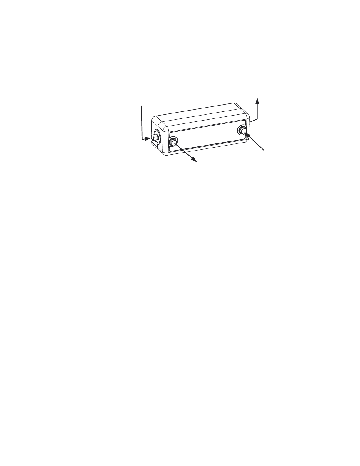
1.2 Dionex Chemicall y Regen erat ed Suppressor Assembly Schematic
The Dionex CRS 500 includes two regenerant compartments and one eluent compartment
separated by ion exchange membranes. The central channel is the eluent channel and the two
side channels are regenerant channels. Two PEEK plates form the outer walls of the regenerant
channels and have t he ¼-28 port s for co nnecti ng the r egene rant li quid li nes. T he elue nt cha nnel
is defined by a PEEK plate that seals against the ion exchange membrane and a thin elastomeric
o-ring installed on the regenerant PEEK plates. The eluent in and out ports are independent
ports that define the fluidic pa thwa y, which i s simi lar to a co lumn The regenerant flo w dir ectio n
is opposite to the elue nt flow direction. This orie ntation ensures complete regeneratio n of the
device.
The regenerant channels are flushed with a regenerant tha t supplies hydronium or hydroxide
ions that are required for the suppression reaction. For the Dionex ACRS 500, the ion e xc han ge
membranes provide the transport pathwa y for the hydronium ions into the eluent channel while
providing a transport pathway for the sodium or potassium ions out o f the eluent cha nnel. For
the Dionex CCRS 500, the ion exchange membranes provide the transport pathway for the
hydroxide ions into the eluent channel while providing a transport pathway for the sulfate or
MSA ions out of the eluent channel. In the Dionex CRS 500 the rege nerant channel is fitted
with unfunctionalized neutral regenerant screens that facilitate excellent transport of ions to and
from the ion exchange membranes without any retention in the regenerant channel. The net
result for both the Dionex ACRS 500 and t he Dionex CCRS 500 is suppression o r conversion of
the eluent from a hi ghly conduc tive for m to a wea kly cond uctive for m and conversion of most
analytes into highly conductive forms.
For example, for the Dionex ACRS 500, sodium hydroxide eluent with residual carbonate is
converted to water and a weakly conductive carbonic acid background, while sodium chloride
analyte is converted to a highly conductive hydrochloric acid form. Thus the analyte, chloride, is
detected as the highly conductive HCl form against a low conductivity water and residual
carbonic acid background. For the Dionex CCRS 500, methanesulfonic acid eluent is converted
to water and the analyte, sodium chloride, is converted to sodium hydroxide. Thus sodium is
detected as the highly conductive NaOH form against a low conductivity water bac kground. It
should be noted that the background of the suppressed eluent may be elevated due to chemical
leakage of the regenerant into the eluent; therefore optimization of the regenerant type,
concentration and flow rate may be needed to minimize this effect.
031727-07
Page 10

1 – Introduction
Thermo Scientific
Product Manual for Dionex CRS 500 Suppressor
Page 10 of 40
Regen In
Regen Out
Eluent In
Eluent Out
Figure 2 Membrane and Flow Chamber Configuration in the Dionex Chemically
Regenerated Suppressors
031727-07
Page 11
1 – Introduction
Thermo Scientific
Product Manual for Dionex CRS 500 Suppressor
Page 11 of 40
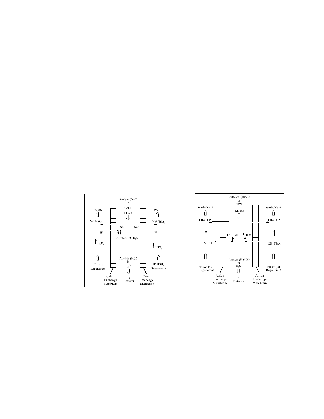
1.3 Chemical Suppression S chematic
Chemical Suppression with the Dionex ACRS 500 is a neutralization reaction and selective
desalting process carried out across a pair of cation exchange membranes. The cation exchange
membranes facilitate the selective exchange of cations in the suppressor. With sodium
hydroxide as the eluent, sodium ions are continuously exchanged for hydronium ions from the
regenerant acid and combine with the eluent hydroxide to form water. The sodium ions are
removed continuously from the suppressor by the regenerant acid stream thus effecting
continuous suppression.
Chemical Suppression with the Dionex CCRS 500 is a neutralization reaction and selective
desalting process carried out across a pair of anion exchange membrane s.. The a nion excha nge
membranes facilitate the selective exchange of anio ns in the supp ressor. Wi th methanes ulfonic
acid as the eluent, the methanesulfonate ions are continuously exchanged for hydroxide ions
from the regenerant base (TBAOH) and combine with the eluent hydronium to form water. The
methanesulfonate anions are removed continuously from the suppressor by the regenerant base
stream thus effecting continuous suppression.
Figure 3 Figure 4
Chemical Suppression with the Chemical Suppression with the
Dionex Anion Chemically Regenerated Dionex Cation Chemically Regenerated
Suppressor (Dionex ACRS 500) Suppressor (Dionex CCRS 500)
031727-07
Page 12
1 – Introduction
Thermo Scientific
Product Manual for Dionex CRS 500 Suppressor
Page 12 of 40
storage or
Ensure the suppressor is stored in a temperature controlled environment away from direct
!
!
1.4 Shipment and Storage
1.4.1 Shipment
The Dionex Chemically Regenerated Sup pressors (Dionex ACRS 500 and Dionex CCRS
500) should not be subjected to temperatures above 60°C during shipment,
operation for extended periods of time.
1.4.2 Storage
exposure to sunlight or other sources of heat. Do not store the suppressor in a nontemperature controlled environment where temperatures in excess of 40°C are commonly
experienced, such as a parked car, a tool shed, or a lab-bench in close proximity to an open
window with direct sunlight.
031727-07
Page 13

1 – Introduction
Thermo Scientific
Product Manual for Dionex CRS 500 Suppressor
Page 13 of 40
1.5 Overview of Suppressio n Modes
Three basic modes of suppression can be used with the Dionex Chemically Regenerated
Suppressor (Dionex CRS 500):
Displacement Chemical Regeneration Mode:
This mode is a se lf-co nta ined mean s of d is pens ing r ege ner ant i nto the Dionex CRS 500 without
any added pumps or delivery systems. The suppressed effluent from the suppressor is directed
from the cell outlet into a closed bottle containing the regenerant. A second line is connected
back from the bottle into the REGEN IN port of the suppressor. Thus t he ce ll e f fl ue nt d r i ves t he
regenerant out of the bottle and into the Dionex CRS 500; the difference in density of the eluent
and regenerant solutions prevent mixing of the two. In this mode, the eluent flow rate
determine s t he regenerant flow rate.
The density of the cell effluent and the regenerant determines the exact location of the line
inside the bottle. For detailed plumbing and operation instructio ns refer to the DCR Kit M anual
(Document No. 031664).
External Chemical Mode:
This mode in the simplest form uses an external regenerant reservoir that is gas pressurized and
dispenses regenerant into the suppressor. The pressure on the container, the liquid level and the
back pressure of the Dionex CRS 500 suppressor and associated tubing determines the flow rate
of the regenerant into the suppressor. An external pump could also be used to dispense the
regenerant, provided the pump is substantially pulse free or has a suitable pulse damper
installed.
AutoRegen Suppression Mode:
This mode has been discontinued by Thermo Scientific and is only included here for legacy
operators.
AutoRegen Suppression mode recycles the regenerant thus enabling continuous operation. A
pump is required in this mode to pump the expended regenerant back into an AutoRegenerant
cartridge to exchange the cations for hydronium ions (Dionex ACRS 500) or the anions for
hydroxide ions (Dionex CCRS 500). Thus, fresh regenerant is made available for the
suppression function.
The following sections explain which mode to use for an application. Once the mode of
operation is determined, more detailed plumbing configuration and operating instructions can be
found in Section 3, “Dionex Chemically Regenerated Suppressor (Dionex CRS 500)
Operation.”
031727-07
Page 14

1 – Introduction
Thermo Scientific
Product Manual for Dionex CRS 500 Suppressor
Page 14 of 40
Eluent
Displacement Chemical
External Chemical
AutoRegen
Aqueous El uents
Yes
Yes
Yes
Eluents Co ntaining
Yes
Yes
Yes
Eluents Co ntaining
Yes
Yes
Yes
1.6 Mode of Operation Selection
The Dionex ACRS 500 uses sulfuric acid as the preferred regenerant to achieve eluent
suppression. The Dionex CCRS 500 uses tetrabutylammonium hydroxide (TBAOH) as the
preferred regenerant to achieve eluent suppression. Both the Dionex ACRS 500 and Dionex
CCRS 500 mode of operation is highly dependent on the ionic strength or concentration of the
eluent used and the analysis sensitivity requirements.
Table 1 Eluent Composition and Suppression Mode Compatibility
Composition
Organic Solvents
Ion Pair Reagents
with/without Solvents
Regeneration Mode
Mode
Suppression
031727-07
Page 15

1 – Introduction
Thermo Scientific
Product Manual for Dionex CRS 500 Suppressor
Page 15 of 40
Regenerant
Regen
IN
Regen
OUT
Eluent
OUT
Eluent
IN
Injection
Valve
Guard
Column
Analytical
Column
Waste
Cell
1.6.1 The Displacement Chemical Regeneration (DCR) Mode
The DCR Mode is the easiest mode to implement and provides convenient and economical
operation in which the regenerant is displaced from the regenerant reservoir using the
conductivity cell effluent. T his mode delivers regenerant to the suppressor at a flow rate equal to
the eluent flow rate. In this mode the regenerant bottle is completely filled with regenerant upon
startup. As the cell effluent is p umped into r eservoir it displa ces the rege nerant solu tion into the
Dionex CRS regenerant chambers. No additional pump or pressure is required. Eluent and
regenerant bottles are of equivalent volumes ensuring that the regenerant solution lasts as long
as the eluent; thus new regenerant needs to be prepared only when new eluent is prepared.
The DCR Mode is recommended for low to medium suppression applications (< 50 ueq/min)
and provides adequate dynamic capacity for the majority of applications. Because regenerant
flow rate is limited to the same flow rate as the eluent, the concentration of the regenerant may
need to be adjusted to achieve full suppression; this may result in increased background
conductivity compared to other modes where the flow rate can be adjusted. As a general rule the
regenerant concentration in mN should be 2 to 5 times the eluent concentration in mN.
Figure 5 The Displacement Chemical Regeneration (DCR) Mode Diagram
031727-07
Page 16

1 – Introduction
Thermo Scientific
Product Manual for Dionex CRS 500 Suppressor
Page 16 of 40
Regenerant
Regen
IN
Regen
OUT
Eluent
OUT
Eluent
IN
Injection
Valve
Guard
Column
Analytical
Column
Waste
Cell
Gas Pressure
25 psi max
Coil #1
Coil #2
1.6.2 The External Chemical Mode
The External Chemical Mode is an easy to implement configuration that dispenses regenerant
using a pressurized regenerant reservoir directly into the suppressor. The concentration of the
regenerant dictates the leakage into the eluent stream therefore lower concentration of the
regenerant is preferred in this mode. The flow rate needs to be adjusted to provide the equivalent
concentration required for suppression. Generally higher flow rates are employed in this
mode resulting in higher waste generation. The regenerant dynamic concentration (mN x
mL/min) should be approximately 7 times the eluent dynamic concentrati on (mN x mL/ min).
The External Chemical Mode is highly recommended for high suppression applications (> 70
µeq/min) and provides the highest dynamic capacities required for these applications.
An external pump could be used for dispensing the regenerant provided the pump is
substantially pulse dampened using a suitable pulse damper. Thermo Scientific recommends the
use of a Peristaltic Pump P/N 064230 along with a Peristaltic Pump Kit (P/N 064911) for this
application.
Figure 6 The External Chemical Mode with the Dionex Chemically Regenerated
Suppressor (Dionex CRS 500)
031727-07
Page 17

1 – Introduction
Thermo Scientific
Product Manual for Dionex CRS 500 Suppressor
Page 17 of 40
1.6.3 The AutoRegen Suppression Mode
This mode has been discontinued by Thermo Scientific and is only incl uded here for legacy
operators.
The Auto Regen Suppression Mo de is another mode for implementing chemical suppression.
This mode is designed to recycle the regenerant and reduce regenerant consumption for high
suppression applications. For the Dionex ACRS 500, the AutoRe ge n Sup p re ssi o n mod e r eq ui re s
the installat io n of the Auto Re gen Acc e ssor y equip pe d with an A uto Rege n Re gener ant Car tri dge
to convert the spent regenerant back to sulfuric acid regenerant. For the Dionex CRS 500, the
AutoRegen S uppression mode r equires the installat ion of the AutoRege n Accessory equipp ed
with an AutoRegen Regenerant Cartridge to convert the spent regenerant back to TBAOH
regenerant. The AutoRegen Suppression Mode is recommended for applications that require
continuous operation without user intervention. The AutoRegen Mode however, is not
recommend ed for appl i cations requiring low no i s e or high sensi tivity.
031727-07
Page 18

2 – Installation
Thermo Scientific
Product Manual for Dionex CRS 500 Suppressor
Page 18 of 40
Required Installation Components
P/N
Description
Back pressure coils:
45877
Backpressure coil 4 mm
45878
Backpressure coil 2 mm
Also Found in:
46297
ED40 Shipkit
46298
CD20 Shipkit
45935
CDM-3 On-Line Ship Kit
50130
DX-120 Ship Kit
Tubing for 4 mm systems:
45825
Standard tubing
(containing tubing, fittings and 4 mm backpressure coils required for plumbing a
4 mm systems)
Tubing for 2 mm / 3 mm systems:
52324
Microbore tubing
(containing tubing, fittings and 2 mm backpressure coils required for plumbing a
2 mm and 3 mm systems)
Regenerant Options:
Pressurized Water Delivery System (used with the External Pressurized Bottle
Mode, the Chemical Suppression Mode, or the MPIC Suppression Mode)
38018
Dionex CRS/SRS Installation Kit
64230
Peristaltic Pump
64911
Peristaltic Pump Kit
AutoRegen Accessory (used with the Chemical Suppr ession Mode)
39594
115 V ac Version
39608
230 V ac Version
39564
Anion Regenerant Cartr idge
39563
Cation Regenerant Cartridge
Displacement Regeneration Kit
56882
Displacement Regeneration 2 Liter K it
56884
Displacement Regeneration 4 Liter K it
2. Installation
2.1 System Requirement s
The Dionex Anion or Cation Chemically Regenerated Suppressor (Dionex CRS 500) is
designed to be run on any Dionex Ion Chromatograph (IC) equipped with an ion exchange
column set and suppressed conductivity detection. The Dionex CRS 500 is installed
immediately after the analytical column and before the conductivity detector cell. The
following components are req uired for the installation o f the Dionex CRS 500 in a Dionex Ion
Chromatograph:
031727-07
Page 19

2 – Installation
Thermo Scientific
Product Manual for Dionex CRS 500 Suppressor
Page 19 of 40
, it may be necessary to
NOTE
!
!
During the course of installing and using the Dionex CRS 500
assemble 1/4-28 or 10-32 ferrule/bolt style liquid lines. See , “Dio nex Liquid Line Fittings,”
for complete details.
2.2 Back Pressure Coils for the Dionex CRS 500
All detector cells require enough back pressure to prevent eluent in the cell from out-gassing
due to abrupt volume changes between the small inner diameter of the connecting t ube and the
relatively larger volume of the cell. Out-gassing creates bubbles in the cell and disrupts detector
responsiveness. Back pressure coils help to prevent gases from out-gassing and prevents
formation of bubbles in the detector cell. For example, carbonate eluent is suppressed to
carbonic acid which is CO
if adequate pressure is not applied. The above out-gassing can trap bubbles in the cell causing
high noise. Therefore Dionex recommends addition of 30-40 psi of backpressure for most
applications.
Back pressure coil components are located in the detector Ship Kits as part of the Gas Separator
Waste Tube Assembly/Back Pressure Coils Kit, P/N 045825. For 4 mm systems, locate
assembly P/N 045877. For 2 mm systems, the backpressure coils are available in the microbore
tubing kit, P/N 052324. For 2 mm syste ms, locate assembl y P/N 04 5878. Alte rnativel y, lengt hs
and diameters of tubing necessary for proper back pressure are given in Table 2, “Coils for
Dionex CRS 500 Back Pressure Requirements.” Adjust the tubing length to achieve a
backpressure of approximately 40 psi.
gas in equilibri um with DI water; CO2 gas can come out of solution
2
If back pressure coils become damaged or plugged, they may cause irreversible damage to
the suppressor.
Assemble as fol l ows:
A. Slip PEEK liquid line bolts and ferrules onto the ends of the tubing. Refer to Table 2,
“Coils for Dionex CRS 500 Back Pressure Requirements,” and determine the correct
number of coils required for your application based on the eluent flow rate.
B. After assembly of the coils, see Figure 8, “Configuration of the External Chemical
Mode with the Dionex CRS 500 Suppressor,” for the proper placement of the
assembled coils and couplers after the detector cell and before the waste container.
031727-07
Page 20

2 – Installation
Thermo Scientific
Product Manual for Dionex CRS 500 Suppressor
Page 20 of 40
Dionex
Flow Rate
I.D. of
Appropriate
Number
4 mm
0.5–1.5 ml/min
0.010" (Black)
2.5 feet
2
4 mm
1.5–3.0 ml/min
0.010" (Black)
2.5 feet
1
2 mm
0.12–0.25 ml/min
0.005" (Red)
6.0 inches
2
2 mm
0.25–0.75 ml/min
0.005" (Red)
6.0 inches
1
!
Table 2 Coils for Dionex CRS 500 Back Pressure Requirements
CRS III
Type
The above recommended length of tubing may vary depending on the I.D. of the tubing.
The correct amount of back pressure for optimum operation is 40 psi.
Back pressure over 150 psi after the Dionex CRS 500 can cause irreversible damage!
Tubing
Length of
Each Coil
of Coils
031727-07
Page 21

2 – Installation
Thermo Scientific
Product Manual for Dionex CRS 500 Suppressor
Page 21 of 40
Regenerant
Regen
IN
Regen
OUT
Eluent
OUT
Eluent
IN
Injection
V
alve
Guard
Column
Analytical
Column
Waste
Cell
2.3 Plumbing for Displacement Chemical Regeneration (DCR) Mode of Operation
Figure 7 The Displacement Chemical Regeneration (DCR) Mode Plumbing Diagram
The Displacement Chemical Regeneration Mode is the easiest method of operation. As the
eluent passes through the suppressor, it is neutra lized to pr oduce its weakly ionized form. After
passing through the conductivity cell, this effluent can be redirected to the regenerant bottle,
thus displac ing t he regene rant (see Figure 7, “The Displacement Chemical Regeneration (DCR)
Mode Plumbing Diagram”). The main advantage of this mode is its simplicity and ease of use. It
is not necessary to use a pump or pressurized bottle.
Depending on the specific components (analytical column, conductivity cell, back pressure
coils) in the system, 1/4-28 or 10-32 ferrule/bolt liquid lines may be required. All necessary
tubing and fittings are supplied in the detector or Ship Kits. To purchase or assemble 1/4-28 or
10-32 ferrule/bolt liquid lines, refer to , “Dionex Liquid Line Fittings.” Always use 0.005" i.d.
PEEK tubing with 10-32 ferrule/bolt fitti ngs on 2 mm systems. Wherever possible use 0.010"
i.d. PEEK tubing with 10-32 ferrule/bolt fittings on 4 mm systems.
031727-07
Page 22

2 – Installation
Thermo Scientific
Product Manual for Dionex CRS 500 Suppressor
Page 22 of 40
egenerant. Refer to the DCR Kit Manual
NOTE
!
A. Install the Dionex Chemically Regenerated Suppressor (Dionex CRS 500) in the
Chromatography Module.
B. Connect the outlet of the analytical column to the ELUENT IN of the Dionex CRS
500. See Figure 7, “The Displacement Chemical Regeneration (DCR) Mode Plumbing
Diagram.” To avoid adding dead volume to the system, make the length of all eluent
lines as short as practically possible. Be sure to butt the tubing tight in the end fitting as
the fitting is tightened.
C. Connect the ELUENT OUT port of the Dionex CRS 500 to the inlet of the
conductivity cell. See Figure 7, “The Displacement Chemical Regeneration (DCR)
Mode Plumbing Diagram.” To avoid adding dead volume to the system, make the
length of all eluent lines as short as practicall y possible. Refer to the DCR Kit Manual
(P/N 031664) for DCR plumbing details.
D. Connect the back pressure line from the cell to the DCR bottle. Connect the second
line from the DCR bottle to the REGEN IN port on the suppressor
The correct tubing orientation in the DCR bottle d epe nds on the d iff erence in the d ensity of
the cell effluent versus the chemical r
(P/N 031664)
031727-07
Page 23

2 – Installation
Thermo Scientific
Product Manual for Dionex CRS 500 Suppressor
Page 23 of 40
Regenerant
Regen
IN
Regen
OU
T
Eluent
OU
T
Eluent
IN
Injection
V
alve
Guard
Column
Analytical
Column
Waste
Cell
Gas Pressure
25 psi max
Coil #1
Coil #2
2.4 Plumbing for External Chemical Mode of Operation
Figure 8 Configuration of the External Chemical Mode with the Dionex CRS 500
Suppressor
The Dionex CRS/ERS Installation Kit (P/N 038018) contains all of the components needed to
install and operate the Dionex CRS 500 with a pressurized regenerant reservoir. The kit contains
the Installat ion Part s Kit (P/N 039055), a 25 psi regulator (P/N 038201) and a 4-liter reservoir
(P/N 039164).
A. Make the following air line connections:
1. Locate the pieces of red 1/8" o.d. plastic tubing (P/N 030089) supplied in the
Installation Parts Kit.
2. Push the end of one piece of 1/8" o.d. tubing over the barbed fitting of the
regulator. Connect the other end of the tubing to the source of air pressure.
3. Push one end of the second piece of 1/8" o.d. tubing over the other barbed fitting of
the regulator. Push the other end of this tubing over the barbed fitting (P/N
030077) in the pressure inlet of the plastic reservoir. See Figure 8, “Configuration
of the External Chemical Mode with the Dionex CRS 500 Suppressor.”
031727-07
Page 24

2 – Installation
Thermo Scientific
Product Manual for Dionex CRS 500 Suppressor
Page 24 of 40
NOTE
!
B. Make the following liquid line connections. See Figure 8, “Configuration of the
External Chemical Mode with the Dionex CRS 500 Suppressor.”
1. Use a coupler (P/N 039056) to connect one end of the 30" tubing assembly (P /N
035727) that comes in the Installation Kit to t he water re servoir. Con nect the other
end of this tubing to the REGEN IN port of the D ionex Chemi cally Rege nerated
Suppressor.
2. Using a coupler (P/N 039056) and a 1/8" o.d. piece of tubing (P/N 035728) from
the Installation Kit, connect one end of this tubing to the REGEN OUT port and
direct the other end to waste.
C. Fill the regenerant reservoir with the recommended regenerant (Refer to Tables 3
or 4, “Matching the Regenerant concentration and flow rate to eluent
concentration and flow rate”). Make sure that the O-ring is inside the cap of the
reservoir before screwing the cap onto the reservoir. Screw the cap onto the reservoir
tightly and place the reservoir near the Chromatography Module.
D. Adjust the regenerant flow rate to approximately 5–10 mL/min. for the Dionex
CRS 500 4 mm and 5–8 mL /min f or the Dionex CRS 500 2 mm.
A safety relief valve on the reservoir regulator prevents pressure grea ter than 25 p si from
being applied to the reservoir.
2.5 Peristaltic Pump installation
For detailed installation i nstructions plea se refer to t he MAST ERFLEX® C/L® Peristaltic Pump
Quick Start Guide (Document No. 065203)
031727-07
Page 25

2 – Installation
Thermo Scientific
Product Manual for Dionex CRS 500 Suppressor
Page 25 of 40
Regenerant
2.6 Plumbing for AutoRegen Suppression Mode of Operation
Figure 9 Configuration of the Dionex CRS 500 Suppressor Using AutoRegen
Injection
Valve
Coil #2
Guard
Column
Waste
Coil #1
Analytical
Column
Eluent
IN
Regen
OUT
Regenerant
Slip-on
Filter
Pressure
Relief
Assembly
Pump
Regen
IN
Cell
Three-way
Manifold
Eluent
OUT
Cartridge
031727-07
Page 26

2 – Installation
Thermo Scientific
Product Manual for Dionex CRS 500 Suppressor
Page 26 of 40
This mode has been discontinued by Thermo Scientific and is only incl uded here for legacy
operators.
The AutoRegen Suppression Mode requires the use of an acid regenerant to neutralize the
eluent. Choose the appropriate sulfuric acid concentration as described in Tables 3 or 4,
"Matching R egenerant Conc entration and Flow Rate to E luent Concentr ation and Flo w Rate."
The following installation instructions assume that your system is configured with an
AutoRegen Ac ce sso r y eq uip p ed with an A nio n Aut oR e ge n Re ge ne ra nt Ca r tr id ge.
To save regenerant preparation time, consumption, and waste, it is recommended that the
AutoRegen Accessory (115 V ac version, P/N 039594; 230 V ac version P/N 039608) be
purchased. The AutoRegen Accessory is designed to be used specifically with Dionex
Chemically Regenerated Suppressors. The AutoRegen Accessory should be equipped with
either an Anio n AutoRegen Regenerant Cartridge (P/N 039564) for the Dionex ACRS 500 or
with a Cati on A uto Re gen Regener ant Ca r tr id ge ( P /N 0 39 5 64 ) for the Dionex CRS 500. Refer to
the AutoRegen Accessory Manual (Document No. 032853) for complete installation
instructions.
A. Connect the 1/8" o.d. tubing fr om the top of the Auto Regen Regenera nt Cartridge to
the REGEN IN port of the Dionex Chemically R egenerate d Suppressor.
B. Connect the 1 /8" o.d. tubing from the regener ant reservoir cap to the REGEN OUT
port of the Dionex Chemically Regenerate d Suppressor.
C. Turn ON the ON/OFF switch on the front of the pump. The unit is ready for
equilibration and operation.
031727-07
Page 27

3 – Operation
Thermo Scientific
Product Manual for Dionex CRS 500 Suppressor
Page 27 of 40
3. Operation
This section provides instructions for the start-up and operation of the Dionex Chemically
Regenerated Suppressor (Dionex CRS 500). The selection and description of each of the
suppression modes of operation are covered.
3.1 Chemical Purity Requiremen t s
Obtaining precise and accurate results requires eluents that are free of ionic impurities.
Chemicals and deionized water used to prepare eluents must have the purities described below.
Low trace impurities a nd lo w p articulate le vels i n elue nts a nd r egenera nts a lso help p rote ct your
Dionex CRS 500 a nd syste m compone nts fro m contami nation. Dionex cannot guarantee proper
Dionex CRS 500 performance when the quality of the chemicals and water used to prepare
eluents has been compromised.
3.1.1 Inorganic Chemicals
Reagent Grade inorganic chemicals should always be used to prepare ionic eluents. Whenever
possible, inorganic chemicals that meet or surpass the latest American Chemical Society
standard for purity (universally accepted standard for reagents) should be used. These inorganic
chemicals will detail the purity by having an actual lot analysis on each label.
For ease of regenerant preparation and guaranteed purity, use Dionex Anion Regenerant
Concentrat e (P/Ns 03 7164, 039601 ). Sulfuric aci d is the recomme nded regene rant for us e with
the Dionex ACRS 500. Wit h the DCR Kit, use Anion Regenera nt Concent rate 75 mL o f 2.0 N
Sulfuric Ac id (P/N 057559) or the 4-Pak (P/N 057555).
Tetrabutylammonium hydroxide (TBAOH) is the recommended regenerant for use with the
Dionex CRS 500. For ease of regenerant preparation and guaranteed purity, use Dionex Ca tion
Regenerant Concentrate ( P/N 039602 ). With the DCR Ki t, use Cation Re generant Conc entrate
100 mL of 2.06 M TBAOH (P/N 057561) or the 4-Pak (P/N 057556).
3.1.2 Solvents
Since solvents used with the Dionex CRS 500 are added to ionic eluents to modify the ion
exchange process or improve sample solubility, the solvents used must be free of ionic
impurities. However, since most manufacturers of solvents do not te st for ionic impurities, it is
important t hat the highest gr ade of solvents available be used. Currently, several manufacturers
are making ultrahigh purity solvents that are compatible for HPLC and spectrophotometric
applicati ons. These ultrahigh purity solve nts will usually ensure that your chromatography is not
affected by ionic impurities in the solvent. Currently at Thermo Fisher Scientific, we have
obtained c onsistent results using High Puri ty Solvents manufa ctured by Burd ick and Jackson
and Optima™ Solvents by Fishe r Chemical.
3.1.3 Deionized Water
The deionized water used to prepare eluents should be degassed Type I Reagent Grade Water
with a specific resistance of 18.2 megohm-cm. The deionized water should be free of ionized
impurities, organics, microorganisms and particulate matter larger than 0.2 µm. It is good
practice to filter eluents thro ugh a 0.2 µm filter whenever po ssible. Bottled HP LC-Grade Water
should not be used since most bottled water contai ns an unacceptable le vel of ionic impurities.
Finally, thoroughly degas all deionized water prior to preparing any eluents or regenerants.
031727-07
®
Page 28

3 – Operation
Thermo Scientific
Product Manual for Dionex CRS 500 Suppressor
Page 28 of 40
This requirement is achieved by
maintaining the regenerant cavities full of the appropriate regenerant solution to ensure that
e membranes remain properly hydrated. Occasionally some of the regenerant solution
long term storage. Before starting an analysis, install your new
!
!
3.2 Start Up
The Dionex CRS 500 is installed in the column compartment of the chromatography module
after the analytical column and before the conductivity detector cell. On all Dionex Ion
Chromatogr aphy Syste ms instru ments, the Dionex CRS 500 mounts o n tabs on the co mponent
panel. Orie nt the Dionex CRS 500 accord ing to the flow d iagram provided with your syste m;
align the slots on the back of the Dionex CRS 500 with the t abs on t he pa nel . Pr ess i n, a nd t hen
slide to lock t he Dionex CRS 500 in place. Slide a nd pull out to re move the Dionex CRS 500.
Make sure the Dionex CRS 500 is plumbed properly, according to the selected mode of
operation. Refer to Section 2, “Installation,” for complete installation instructions.
The membranes, resin and screens in the Dionex CRS 500 must be completely hydrated to
maintain liquid seals and chromatographic performance.
th
evaporates during mid to
Dionex CRS 500 and pump regenerant solution through the suppressor until you see no more
bubbles. Turn off the flow and let the Dionex CRS 500 sit for at least 20 minutes to ensure
that the membranes are fully hydrated before pumping eluent through the suppressor.
The correct amount of back pressure for optimum operation is 40 – 60 psi. Connect the
back pressure coil(s) appropriate for your column I.D. and flow rate. Back pres sures over
150 psi after the Dionex CRS 500 can cause poor peak shapes. Back pressure s o ve r 300 psi
after the Dionex CRS 500 can cause irreversible damage!
031727-07
Page 29

3 – Operation
Thermo Scientific
Product Manual for Dionex CRS 500 Suppressor
Page 29 of 40
Eluent Flow Rat e
Regenerant Fl o w Rate
Regenerant Co nc
Eluent
(mL/min)
(mL/min)
(mN H2SO4)
1.8 mM Na2CO3/1.7 mM NaHCO
0.5–2.0
3–5
25
9.0 mM Na2CO3 0.5–2.0
3–5
50
1.0 - 100 mM NaOH
0.5–1.5
3–10
50–100
1.0 - 100 mM KOH
0.5–1.5
3–10
50–100
20 - 50 mM Na2B4O
0.5 - 1.5
5–10
50-100
Eluent Flow Rat e
Regenerant Fl o w Rate
Regenerant Co nc
Eluent
(mL/min)
(mL/min)
(mN H2SO4)
1.8 mM Na2CO3/1.7 mM NaHCO
0.10–0.50
3–5
25
2.7 mM Na2CO3/0.3 mM NaHCO
0.10–0.50
3–5
25
9.0 mM Na2CO3 0.10–0.50
3–5
50
1.0 - 100 mM NaOH
0.10–0.50
3–8
50
100 - 150 mM NaOH
0.10–0.50
5–8
50–100
1.0 - 100 mM KOH
0.10–0.50
3–8
50
100 - 150 mM KOH
0.10–0.50
5–8
50–100
30 - 75 mM Na2B4O
0.10–0.38
5–8
50–100
3.3 Optimizing Regenerant Concentration and Flowrate
3.3.1 Anion Regenerant Concentration for Optimized Operation i n Exte r nal Chemical and AutoRegen Modes
The Dionex ACRS 500 has the ability to provide continuous suppression of eluents using
chemical regeneration with an acid such as sulfuric acid (H
Regenerant Concentration and Flow Rate to Eluent Concentration and Flow Rate”, list the
eluent concentrations and flow rates of standard eluents used in anion separations and the
regenerant concentrations and flow rates required to suppress them. Optimal operation of the
Dionex ACRS 500 requires a constant flow of the regenerant over the membrane, in a direction
that is countercurrent to the flow of the eluent. A standard regenerant flow rate of 5–10 mL/min
is recommended for the External Chemical Mode of operation.
This flow rate is adequate for most applications. For applications that require stronger than
typical eluent strengths, the regenerant flow rate may be increased. The level of chemical
leakage increases with increasing concentration hence it is critical that the concentration of
regenerant be as low as possible in order to achieve low backgrounds.
Table 3 Matching Regenerant Concentration and Flow Rate to Eluent Concentration
and Flow Rate for the 4 mm Dionex ACRS 500 in the Chemical Suppression
Mode
). Tables 3 or 4, “Matching
2SO4
3
2.7 mM Na2CO3/0.3 mM NaHCO
3.5 mM Na2CO3/1.0 mM NaHCO
1.0 - 20 mM Na2B4O
7
7
3
3
Table 4 Matching Regenerant Concentration and Flow Rate to Eluent Concentration
3
3
3.5 mM Na2CO3/1.0 mM NaHCO
1.0 - 30 mM Na2B4O
7
7
3
0.5–2.0 3–5 25
0.5–2.0 3–5 25
0.5–2.0 5–10 50
and Flow Rate for the 2 mm Dionex SCRS 500 in the Chemical Suppression
Mode
0.10–0.50 3–5 25
0.10–0.50 5–8 50
031727-07
Page 30

3 – Operation
Thermo Scientific
Product Manual for Dionex CRS 500 Suppressor
Page 30 of 40
Maximum Eluent
Regenerant
Eluent Flow Rate
Concentration
Concentration
Eluent
(mL/min)
(mM)
(mM TBAOH)
MSA
1
65
100
Hydrochloric acid 1 75
100
Sulfuric Acid 1 30
100
Nitric Acid 1 50
150
HSA
1 5 100
HSA + 10% ACN 1 7
100
OSA
1 2 100
OSA + 10% ACN 1 2
100
NOTE
!
For the lower eluent concentration in a given range, choose lower corresponding
regenerant concentration; for higher eluent concentration choose higher regenerant
concentration.
Most solve nts suc h as me than ol have l ittle or no e ffect o n the Anio n Rege nerant Solut ion when
using an AutoRegen Accessory unit.
For the best s ignal-to-noise ratio and the best overall perfo rmance when using an Aut oRegen
Cartridge to supply regenera nt, Dionex reco mmends that the A nion Regenerant So lution used
with the Dionex ACRS 500 be replaced on a regular basis. The time interval between changing
the regenerant will depend o n both the time that the instrument is in ope ration and the specific
application. As a guideline, the regenerant should be replaced whenever the background
conductivity drifts to higher levels than t hose observed in the initial chromatogra ms. See the
Installation Instructions and Troubleshooting Guide for the analytical column being used in your
application for a guideline on the expected background conductivity. Tables 3 or 4, “Matching
Regenerant Concentration and Flow Rate to Eluent Concentration and Flow Rate,” list the
appropriate regenerant concentration for selected eluents.
3.3.2 Cation Regenerant Concentration for Optimized Operation for External Chemical and AutoRegen Modes
The Dionex CCRS 500 has the ability to provide continuous suppression of eluents using
chemical regeneration with a base. Tables 5 or 6, “Practical Maximum Eluent Concentration
Suppression Guidelines,” list the practical maximum eluent concentrations and flow rates of
standard el uents used in cation separations versus the regener ant conce ntrations a nd flow rate s
required to suppress them. The operation of the Dionex CCRS 500 requires a constant flow of
the regenerant over the membrane, in a direction that is countercurrent to the flow of the eluent.
A standard regenerant flow rate of 5–10 mL/min is recommended for the External Chemical
Mode of operation.
This flow rate is adequate for most applications. For applications that require stronger than
typical eluent strengths, the regenerant flow rate may be increased. The level of leakage
increases with increasing concentration hence it is critical that the concentration of regenerant
be as low as possible in order to achieve low backgrounds.
Table 5 Dionex CCRS 500 4 mm Practical Maximum Eluent Concentration
Suppression Guidelines Regenerant Flow Rate = 10 mL/min
* For suppressing higher concentrations then listed above, the regenerant concentrations may be increased to 150 mM TBAOH
031727-07
Page 31

3 – Operation
Thermo Scientific
Product Manual for Dionex CRS 500 Suppressor
Page 31 of 40
Maximum Eluent
Regenerant
Eluent Flow Rate
Concentration
Concentration
Eluent
(mL/min)
(mM)
(mM TBAOH)
MSA
0.5
45
100
MSA
0.3
70
100
MSA
0.25
95
100
Hydrochloric acid
0.5
75
100
Hydrochloric acid
0.3
100
100
Hydrochloric acid
0.25
110
100
Sulfuric Acid
0.5
20–25
100
Sulfuric Acid
0.3
25–30
100
Sulfuric Acid
0.25
30–35
100
Nitric Acid
0.25
75
100
HSA
0.25 5 100
HSA + 10% ACN
0.25 7 100
OSA
0.25 2 100
OSA + 10% ACN
0.25 2 100
Eluent Flow Rate
Regenerant Flow Rate
Regenerant Conc
Eluent
(mL/min)
(mL/min)
(mM TBAOH)
5-25 mM HCl
1.0–3.0
3–5
50
25-50 mM HCl
0.5–1.5
5–10
100
25 mM HCl/ 0.25 mM DAP
1.0–2.0
3–5
50
40-50 mM HCl/2-8 mM DAP
0.5–1.5
5–10
100
Eluent Flow Rate
Maximum Suppressible
Regenerant Conc
Eluent
(mL/min)
(mM)
(mM TBAOH)
5-25 mM HCl
0.1–0.50
3–5
50
25-50 mM HCl
0.1–0.50
5–10
100
50-75 mM HCl
0.1–0.40
5–10
100
25 mM HCl/0.25 mM DAP
0.1–0.50
3–5
50
40-60 mM HCl/2-10 mM DAP
0.1–0.40
5–10
100
Table 6 Dionex CCRS 500 2 mm Practical Maximum Eluent Concentration
Suppression Guidelines Regenerant Flow Rate = 8 mL/min
For customers with older systems that use HCl·DAP eluents, the following tables list the practical eluent
concentrations and flow rates of standard DAP/HCL eluents versus the regenerant concentrations and flow rates
required to suppress them.
Table 7 Dionex CCRS 500 4 mm Regenerant Concentration and Flow Rate Versus
Eluent Concentration and Flow Rate for DAP/HCl Eluents
Table 8 Dionex CCRS 500 2 mm Regenerant Concentration and Flow Rate Versus
Eluent Concentration and Flow Rate for DAP/HCl Eluents
031727-07
where:
DAP = DL-2,3-Diaminopropionic acid monohydrochloride (P/N 039670)
Page 32

3 – Operation
Thermo Scientific
Product Manual for Dionex CRS 500 Suppressor
Page 32 of 40
For the lower eluent concentration in a given range, choose lower corresponding
rate arrived at by using the above equations is necessarily the
optimum flow rate. Instead, consider it a good starting point. By monitoring the suppressor
performance, background and noise and by either increasing or decreasing the flow rate as
NOTE
!
NOTE
!
regenerant concentration; for higher eluent concentration choose higher regenerant
concentration.
For the best signal-to-noise ratio and the best overall performance, when using an AutoRegen
Cartridge to supply regenera nt, Dionex reco mmends that the Cation Regenera nt Solution used
with the Dionex CRS 500 b e replaced on a regular basis. The time interval between changing
the regenerant will depend o n both the time that the instrument is in ope ration and the specific
application. As a guideline, the regenerant should be replaced whenever the background
conductivity drifts to higher levels than t hose observed in the i nitial chromatogra ms. See the
Product Manual for the analytical column being used in your application for a guideline on the
expected background conductivity.
3.3.3 Calculations for Regenerant Concentration
The regenerant dynamic concentration (mN x mL/min) should be approxi mately 7 times the
eluent dynamic concentration.
7.(eluent mN)(eluent mL/min)=(regenerant mN)(regenerant mL/min)
Therefore:
(
regenerant mL/min)=
Example #1 Eluent: 50 mN NaOH
Eluent Flow Rate: 1.5 mL/min
A. Regenerant Concentration = 50 mN H2SO4
(
regenerant mL/min)=
B. Regenerant Concentration = 100 mN H2SO4
(
regenerant mL/min)=
Example #2 Eluent: 2.8 mM NaHCO3/2.2 mM Na2CO3
Eluent Flow Rate: 2.0 mL/min
A. Regenerant Concentration = 50 mN H2SO4
Eluent Concentration = 2.8 mN + (2 x 2.2) mN = 7.2 mN
(
regenerant mL/min)=
7.(eluent mN)(eluent mL/min
(
regenerant mN
7.(50 mN)(1.5 mL/min
7.(50 mN)(1.5 mL/min
7.(7.2 mN)(2.0 mL/min
(
50 mN
(
100 mN
(
50 mN
)
)
)
)
=10 mL/min
)
)
=5 mL/min
)
)
=2 mL/min
Do not assume that the flow
required, you should be able to determine the optimum flow rate.
031727-07
Page 33

3 – Operation
Thermo Scientific
Product Manual for Dionex CRS 500 Suppressor
Page 33 of 40
NOTE
!
B. Dionex Anion Regenerant Concentrate (P/Ns 037164, 039601) should be used to make
regenerants for the Dionex Anio n Chemically Regenerated Sup pressors beca use of its
ease of use and guaranteed high purity. With the DCR Kit, use Anion Regenerant
Concentrate 75 mL of 2.0 N Sulfuric Acid (P/N 057559) or the 4-Pak (P/N 057555).
C. Solutions such as methanol and acetonitrile, have little or no effect on the Anion
Regenerant Solution using an AutoRegen System. And, most solvents such as
methanol have little or no effect on the Cation Regenerant Solution when using an
AutoRegen Ac ce sso r y uni t.
D. For the best signal to noise ratio and the best over all pe rformance, Dionex recommends
that the Anion Regenerant Solution used with the Dionex Anion Chemically
Regenerated Suppressors be replaced on a regular basis. Tables 3 or 4, “Matching
Regenerant Co ncentration a nd Flow Rate to Elue nt Concentrat io n and Fl o w Ra te,” list s
the appropriate regenerant concentrations for selected eluents.
3.3.4 Regenerant Concentration for DCR Mode
For anion analysis, X equivalents of eluent requires at least a factor of 2X equivalents of
regenerant in the DCR mode of operation. For catio n analys is, X eq uivale nts of e luent requires
at least a factor of 5X equivalents of regenerant in the DCR mode of operation. Since the flow is
constant, this mode provides improved performance. Refer to DCR Kit Manual (P/N 031664)
for detailed information on the regene rant concentrations.
3.4 Storage
The Dionex Chemically Regenerated Suppressor (Dionex CRS 500) is shipped with DI water as
the storage solution. If a suppressor will not be used for more than one week, prepare it for
storage. The screens and membranes in the Dionex CRS 500 must be completely hydrated to
maintain liquid seal and chromatographic performance.
3.4.1 Short Term Storage (1 to 5 days)
A. Plug both el uent ports. Using a plastic syringe, gently push deio nized water through the
REGEN In port until all bubbles are removed. Plug both regenerant ports.
B. To resume operation, connect the suppressor to the system. Allow the system to
equilibrate before starting you r analysis.
If the eluent last used contained organic so lvents, flush th e Dionex CRS 500 with deio nized
water for 10 minutes through both chambers before plugging the fitting ports.
3.4.2 Long Term Storage
A. Flush the Dionex CRS 500 with deionized water for 10 minutes.
B. Plug the Dionex CRS 500 eluent ports and regenerant ports.
C. To resume operation, connect the suppressor to the system. Turn on the regenerant
flow and al low regene rant to flow un til no mo re bubble s exit the regen o ut port. Turn
off the regenerant flow and allow the suppressor to hydrate for at least 20 minutes.
D. Allow the system to equilibrate befor e starting analysis.
E. If small analyte peak areas are observed when using the DCR mode, perfor m steps A–
C as outlined in APPENDIX B, “QuickStart for the Displacement Regenerant Mode.”
031727-07
Page 34

4 – Troubleshooting Guide
Thermo Scientific
Product Manual for Dionex CRS 500 Suppressor
Page 34 of 40
4. Troubleshooting Guide
The purpose of the Troubleshooting Guide is to help you solve operating problems that may
arise while using the Dionex Chemica ll y Regener ated Suppressor (Dionex CRS 500). For more
information on problems that originate with the Ion Chromatograph or the specific Anion
exchange column set in use, refer to the Troubleshooting Guide in the appropriate Installation
Manual. If you cannot solve the problem on your own, contact the Dionex Regional Office
nearest you (see, “Dionex Worldwide Offices”).
4.1 Small Analyte Peak Areas
If small peak areas are observed when working with a pressurized reservoir
A. Stop the eluent flow while flowing regenerant flow into the suppressor for 5 minutes
B. If peak respo nse has not reco vered then perfor m quick start p rocedure as outlined in
APPENDIX A, “QuickStart for the External Chemical Mode and the AutoRegen
Mode.”
C. In the DCR mode if the above problem is observed then follow instructions outlined in
APPENDIX B, “QuickStart for the Displacement Regenerant Mode.”
D. If the correct peak areas are not observed following two injections of a standard test
solution, contact the nearest Thermo Scientific Regional Office (see, “Thermo
Scientific Worldwide Offices” ).
4.2 High Background Conductivity
A. Check that the regenerant is flowing from the waste line at the proper flow rate.
1. If there is no flow from the waste line, disconnect the 0.012" i.d. tubing connected
to the waste line. If the regenerant lines and the suppressor are filled with
regenerant and there are no restrictions in the regenerant line, the regenerant shoul d
flow freely from the 1/8" o.d. waste line. If there is no flow, make sure the
reservoir cap is tight and that there are no audible air leaks. Also make sure that the
regenerant reservoir is pressurized. If it is, trace the regenerant lines backward
from the reservoir to find and remove any blockage.
2. If there is flow from the waste line, but it is less than the de sired flo w rate, increase
the flow rate b y shortening the 0.012" i .d. waste line tubi ng or by increasing t he
reservoir pressure. If the flow rate is correct, go on to the next step.
3. If the regenerant is flowing at the desired rate, either the selected regenerant flow
rate is too slow or the regenerant is too dilute to suppress the eluent concen tration
at the set eluent flow rate. Refer to Tables 3 or 4, “Matching Regenerant
Concentration and Flow Rate to Eluent Concentration and Flow Rate,” for the
Dionex ACRS 500 or to Tables 5 and 6, “Practical Maximum Eluent Concentration
Suppression Guidelines,” for the Dionex CCRS 500 and then increase the
regenerant flow rate or increase the regenerant concentration.
031727-07
Page 35

4 – Troubleshooting Guide
Thermo Scientific
Product Manual for Dionex CRS 500 Suppressor
Page 35 of 40
!
B. Check for eluent flow out of the suppre s s or ELUENT OUT port.
Do NOT attempt to disassemble the Dionex Chemically Regenerated Suppressor!
C. Remake the regenerant to be sure that the concentration is correct and that the solution
D. Remake the eluent to be sure that the concentration is correct. Be sure that chemicals of
E. If the background conductivity remains high, and you cannot solve t he problem on
4.3 Drifting Baseline
1. If there is no flow out of the Dionex CRS 500 ELUENT OUT p o rt , ma ke s ure tha t
eluent is enterin g t he s upp r es s or a t the ELU EN T IN port. If there is no flo w at this
point, trac e the e lue nt flow path back war d t hro ug h t he s ystem to find and r emo ve
the blockage.
2. If there is flow of elue nt into the Dionex CRS 500 but not out, and there are no
visible leaks from the side seams of the supp r esso r, a break in the o-ring seal or t he
membrane is probably allowing eluent to leak into the regenerant. If this is the
case, then the Dionex CRS 500 must be replaced.
3. If there is flow from the ELUENT OUT port, but no eluent suppression, the
membrane may have been contaminated. Try to restore system performance by
cleaning the membrane (see Section 5, “Suppressor Cleanup”).
has been freshly prepared. Be sure that chemicals of the required purity were used to
make the regenerant (see Section 3.1, “Chemical Purity Requirements”). If the
regenerant concentration is too high or too old, it can cause high background
conductivity.
For the Dionex ACRS 500, Dionex recommends the use of D i onex Anion Regenerant
Concentrate (P/Ns 037164, 039601) for the best performa nce. With the DCR Kit, use
Anion Regenerant Concentrate 75 mL of 2.0 N Sulfuric Acid (P/N 057559) or the 4Pak (P/N 057555).
For the Dionex CRS 500, Dionex r ecommends the use of Di onex Cation Regenerant
Concentrate (P/N 039602) for the best performance. With the DCR Kit, use Cation
Regenerant Concentrate 100 mL of 2.06 M TBAOH (P/N 057561) or the 4-Pak (P/N
057556).
the required purity were used to make the eluent (see Section 3.1, “Chemical Purity
Requirements”). If the eluent concentration is t oo high, the Dionex CRS 500 will not
be able to suppress it, resulting in high background conductivity. Refer to Tables 3 or
4, “Matching Regenera nt Concentration and Flow Rate to Eluent Concent ration and
Flow Rate,” for the Dionex ACRS 500 or to Tables 5 and 6, “Practical Maximum
Eluent Concentration Suppres sion Guidelines,” for the Dionex CCRS 500 and then
increase the regenerant flow rate or increase the regenerant concentration.
your own, contact the Thermo Scientific Regional Office nearest you (see, Thermo
Scientific Worldwide Offices).
If the baseline drifts steadily upward, increase the regenerant flow rate, or if using DCR Mode
increase the r egenerant co ncentration to r ed uce the b ac kground conductivity. As t he b a ck gr ound
conductivity decreases, the baseline usually levels.
031727-07
Page 36

4 – Troubleshooting Guide
Thermo Scientific
Product Manual for Dionex CRS 500 Suppressor
Page 36 of 40
4.4 Decreased Sensitivity
A. Chec k for leak s throughout the syste m. If a fittin g is leakin g, tighten it carefully u ntil
the leak stops. Do not overtighten. If the Dionex CRS 500 is observed to be leaking
from the center or bottom seam, see Section 4.6, “Liquid Leaks.” If you cannot cure the
problem yourself, call the nearest Dionex Regional Office (see, “Dionex Regional
Offices”) for assistance.
B. Ensure that the inj ection valve is operating correctly. Refer to the valve manuals that
accompany the chromatography module for troubleshooting assistance. Be sure to
check the slider port faces for damage.
C. If sensitivity remains low, clean the suppressor membrane (see Section 5, “Suppressor
Cleanup”).
D. Replace the Dionex CRS 500 if cleaning the suppressor membrane does not restore
sensitivity.
E. Chec k the backp ressure co ils. Verif y that they a re not exc eeding 40 p si in the c urrent
plumbing configuratio n and flow rat e.
F. Contact the nearest Thermo Scientific Regional Office (see, “Thermo Scientific
Worldwide Offices”) if you cannot solve the problem on your own.
4.5 System Back Pressure Increases Over Time
A. If the increased back pressure does not affect system performance, no maintenance is
necessary.
B. Check the inlet frits on the guard and analytical column and replace them if necessary.
The most common cause of increasing system back pressure is a contaminated frit in
the analytical or guard colu mn i nlet end fitti ng. The complete instructions for replacing
column bed support assemblies are in column Product Manuals. Recheck the system
back pressure. If it remains high, go on to the next step.
C. Check the backpressure coils. If removing the backpressure coils lowers the pressur e
by more than 40 psi, replace the coils or remove the blockage causing the increased
pressure. Backpressure over 125 psi after the suppressor can cause irreversible damage.
D. Find and eliminate any system blockage. Bypass the Dionex CRS 500 by coupling the
lines attached to the ELUENT IN and ELUENT OUT ports. If the back pressure
decreases by less than 150 psi with the Dionex ACRS 500 out o f line , a b lo c kage i n the
system rather than in the Dionex CRS 500 is causing the high pressure.
E. Remove a blockage from Dionex CRS 500 by r eversing the eluent flow. If the back
pressure decreases by more than 150 psi with the Dionex CRS 500 o ut o f line , t he hig h
pressure may be caused by a blockage in the Dionex Chemically Regenerated
Suppressor. Reverse the direction of flow of the eluent or both the eluent and the
regenerant thro ugh t he Dio nex Chemica lly R ege nerate d Suppressor. After the pressure
drops, allow eluent, or eluent and regenera nt, to flo w to waste for several mi nutes after
the pressure drops. Perform step A of Section 3.2, “Start Up,” and reinstall the Dionex
CRS 500 in the appropriate configuration.
F. Clean the suppressor membranes if reversing the flow thro ugh the Dionex CRS 500
does not decrease the pressure. (See Section 5, “Suppressor Cleanup”).
G. Replace the Dionex CRS 500 if cleaning the suppressor membrane does not reduce the
pressure.
H. Contact the nearest Thermo Scientific Regional Office (see, “Thermo Scientific
Regional Offices”) if you cannot so lve the problem on your own.
031727-07
Page 37

4 – Troubleshooting Guide
Thermo Scientific
Product Manual for Dionex CRS 500 Suppressor
Page 37 of 40
4.6 Liquid Leaks
A. If there is leakage from the ports of the Dionex CRS 500, c arefully t ighte n the fitt ings
in the ELUENT and REGEN IN and OUT ports – be careful not to over-tighten the
fittings. If tightening the fittin gs does not stop the leak, replace the fittings and ferrules.
B. If there is leakage from the side seam of the Dionex CRS 500, check the cell and
backpressure coil backpressure.
1. If the backpressure is greater than 200 psi, the leaks are caused by excessive
backpressure downstream from the Dionex CRS 500. Find and eliminate the source
of the pressure.
2. If the backp ressure i s less tha n 150 psi, the Dionex CRS 500 is the cause of high
backpressure; follow step C or go to Chapter 5, Suppressor Cleanup. Do not
disassemble the Dionex CRS 500 and attempt to repair it yourself!
C. If the Dionex CRS 500 is leaking due to excessive internal backpressure (>200 psi), the
suppressor may need to be back-flushed.
1. Turn off the pump.
2. Disconnect the Column Out line from the Suppresso r Eluent In port. Disconnect
the Suppressor Eluent O ut port.
3. Connect the Column Out line to the Suppressor Eluent Out port.
4. Connect a piece of tubing to the Suppressor Eluent In port and run this line to
waste.
5. Turn the p ump on and pump eluent through the suppressor at the standa rd flow rate
for 5 minutes; ensure the po wer to the suppressor is turned off during this step.
6. Turn off the pump.
7. Reconnect the Eluent In and Eluent Out connections in their correct orientation.
D. For issues with DCR operation, refer to the DCR Kit Man ual (P/N 031664).
E. For i ssues with AutoRe gen operatio n, refer to the Auto Regen Cartrid ge Manual (P/N
032852).
031727-07
Page 38

5 – Suppressor Cleanup
Thermo Scientific
Product Manual for Dionex CRS 500 Suppressor
Page 38 of 40
Bypassing internal pump manifolds when temporarily pumping high concentration
NOTE
!
5. Suppressor Cleanup
This section describes routine cleanup procedures for the Dionex Chemically Regenerated
Suppressors (Dionex CRS 500) in the case of contamination. Consult the Troubleshooting
Guide (see Section 4, “Troubleshooting G uide”) to first determine that the system is operating
properly. If the Dionex CRS 500 is determined to be the source of higher than normal back
pressure, higher than anticipated conductivity, decreased suppression capacity or decreased
sensitivity, cleaning the membrane may restore the performance of the system. Use the
following procedures to clean the membrane.
Metal Contaminants or Precip itates with the Dionex CRS 500 Disconnect the analytical (and
guard) column(s) from the injection valve and the Dionex CRS 500. Refer to the specific
analytical column Installation Instructions and Troubleshooting Guide for column cleanup
procedures.
A. T urn off the external regenerant and disconnect the external regenerant line from the
Dionex CRS 500 REGEN IN port.
B. Disconnect the liquid line from the Dionex CRS 500 ELUENT OUT port to the cell at
the cell fitting and reconnect it to the REGEN IN port.
C. Pump a solution of 0.2 M oxalic acid through the Dionex CRS 500 eluent chamber at
1 – 2 mL/min (4 mm) or 0.25 – 0.5 mL/ min ( 2 mm). I f us ing t he el uent pu mp, c onnect
a temporary line from the priming bloc k or the low-pressure tee of the pump to the
oxalic acid container to avoid contaminating the pump manifolds.
cleaning solutions significantly reduces the time required to re-equilibrate the system to
low concentration eluents.
D. Flush the Dionex CRS 500 with deionized water for 10 minutes.
E. Perform a QuickStart procedure as outlined in Section 3.2, “Start Up.”
F. Install the Dionex CRS 500 unit back on t he system and pump regene rant thro ugh the
regenerant chamber. Turn o n the eluent after flus hing the regenera nt chamber. In the
DCR mode, turning o n the eluent flow is needed to push the regenerant into the Dionex
CRS 500.
G. Flush the Dionex CRS 500 with eluent for 10 minutes.
H. Reinstall the analytical (and guard) column(s). Begin pumping eluent through the
system at the flow rate required for your analysis and equilibrate the system.
031727-07
Page 39

5 – Suppressor Cleanup
Thermo Scientific
Product Manual for Dionex CRS 500 Suppressor
Page 39 of 40
temporarily pumping high concentration
NOTE
!
5.1 Base-Soluble Contaminants or Precipitates with the Dionex CRS 500
A. Disconnect the analytical (and guard) column(s) from the injection valve and the
Dionex CRS 500 Refer to t he specific analytical column Product Manual for column
cleanup procedures.
B. Turn off the re generant and d isconnect t he regenerant line from the Dionex CRS 500
REGEN IN port.
C. Disconnect the liquid line fro m the Dionex CRS 500 ELUENT OUT port to the cell at
the cell and reconnect it to the REGEN IN port.
D. Pump a solution of 0.1 M NaOH through the Dionex CRS 500 eluent chamber at 1 – 2
mL/min (4 mm) or 0.25 – 0.5 mL/min (2 mm). If using the eluent pump, connect a
temporary line from the priming block or the low-pressure tee of the pump to the
sodium hydroxide container to avoid contaminating the pump manifolds.
Bypassing internal pump manifolds when
cleaning solutions significantly reduces the time required to re-equilibrate the system to
low concentration eluents.
E. Flush the columns and the Dionex CRS 500 separately with deionized water, having a
specific resistance of 18.2 megohm-cm, for 10 minutes.
F. Perform a QuickStart procedure as outlined in Section 3.2, “Start Up.”
G. Install the Dionex CRS 500 u nit back on t he system a nd pump re generant t hrough t he
regenerant chamber. Turn o n the eluent after flus hing the regenera nt chamber. In the
DCR mode, turning o n the eluent flow is needed to push the regenerant into the Dionex
CRS 500.
H. Flush the Dionex CRS 500 with eluent for 10 minutes.
I. Reinstall the analytical (and guard) column(s). Begin pumping eluent through the
system at the flow rate required for your analysis and equilibrate the system.
031727-07
Page 40

5 – Suppressor Cleanup
Thermo Scientific
Product Manual for Dionex CRS 500 Suppressor
Page 40 of 40
Bypassing internal pump manifolds (when temporarily pumping high concentration
NOTE
!
5.2 Organic Contaminants with the Dionex ACRS 500 or Dionex CCRS 500
A. Disconnect the analytical (and guard) column(s) from the injecti on valve and the
Dionex CRS 500. Refer to the specific analytical column Product Manual for column
cleanup procedures.
B. If you are running in the External Chemic al Mode, tur n off the external regenerant and
disconnect the external regenerant line from the Dionex CRS 500 REGEN IN port. If
you are running in the Displacement Chemical Regeneration Mode, proceed to D.
C. Disconnect the liquid line from the Dionex CRS 500 ELUENT OUT port to the cell at
the cell fitting and reconnect it to the REGEN IN port.
D. For the Dionex ACRS 500, connect a temporary line from the priming block or the
low-pressure tee on the isocratic or gradient pump to a container with a solution of
freshly prepared 10% 1.0 M HCl/90% a c e tonitrile or methanol. HCl/acetonitrile
solutions are not stable during long term storage so this cleanup solution must be made
immediately before each column cleanup. Alternatively, it can be proportioned from a
bottle containing 1.0 M HCl and another bottle containing 100% acetonitrile.
For the Dionex CCRS 500, connect a temporary line from the priming block or the
low-pressure tee on the isocratic or gradient pump to a container with a solution of
90% acetonitrile or methanol in water.
Pump the appropriate solution given above through the Dionex CRS 500 (4 mm) at 1-2
mL/min for 30 minutes. For 2 mm systems, pump this s olution thr ough the Dionex
CRS 500 (2 mm) at 0.25–0.50 mL/min for 30 minutes.
cleaning solutions) will significa ntly reduce the time required to re-equilibrate the system
to low concentration eluents.
E. Flush the Dionex CRS 500 with deionized water for 10 minutes.
F. Perform a QuickStart procedure as outlined in Section 3.2, “Start Up.”
G. Install the Dionex CRS 500 u nit back on t he system a nd pump re generant t hrough t he
regenerant chamber. Turn o n the eluent after flus hing the regenera nt chamber. In the
DCR mode, turning o n the eluent flow is needed to push the regenerant into the Dionex
CRS 500.
H. Flush the Dionex CRS 500 with eluent for 10 minutes.
I. Reinstall the analytical (and guard) column(s). Begin pumping eluent through the
system at the flow rate required for your analysis and equilibrate the system.
031727-07
 Loading...