

Page 1

Thermo Scientific
Dionex Aquion RFIC Ion
Chromatography System
Operator’s Manual
22176-97006 Revision 01 March 2019
Page 2

© 2019 Thermo Fisher Scientific Inc. All rights reserved.
Chromeleon, ERS, and OnGuard are registered trademarks of Thermo Fisher Scientific Inc. in the United
States. Microsoft and Windows are registered trademarks of Microsoft Corporation in the United States and
other countries.
KIMWIPES is a registered trademark of Kimberly-Clark Corporation in the United States and possibly other
countries.
PEEK is a trademark of Victrex PLC. Rheodyne is a trademark of IDEX Health & Science LLC.
All other trademarks are the property of Thermo Fisher Scientific Inc. and its subsidiaries.
Thermo Fisher Scientific Inc. provides this document to its customers with a product purchase to use in the
product operation. This document is copyright protected and any reproduction of the whole or any part of this
document is strictly prohibited, except with the written authorization of Thermo Fisher Scientific Inc.
The contents of this document are subject to change without notice. All technical information in this
document is for reference purposes only. System configurations and specifications in this document supersede
all previous information received by the purchaser.
This document is not part of any sales contract between Thermo Fisher Scientific Inc. and a purchaser. This
document shall in no way govern or modify any Terms and Conditions of Sale, which Terms and Conditions of
Sale shall govern all conflicting information between the two documents.
Release history: Revision 01 released March 2019; initial system release
Software version: Chromeleon 7.2.9 DUa and later
For Research Use Only. Not for use in diagnostic procedures.
Page 3

C
Contents
Preface . . . . . . . . . . . . . . . . . . . . . . . . . . . . . . . . . . . . . . . . . . . . . . . . . . . . . . . . . . . . . . .v
Related Documentation . . . . . . . . . . . . . . . . . . . . . . . . . . . . . . . . . . . . . . . . . . . v
Safety Information . . . . . . . . . . . . . . . . . . . . . . . . . . . . . . . . . . . . . . . . . . . . . . .vi
Safety and Special Notices . . . . . . . . . . . . . . . . . . . . . . . . . . . . . . . . . . . . . . . .vi
Safety Symbols . . . . . . . . . . . . . . . . . . . . . . . . . . . . . . . . . . . . . . . . . . . . . . . vii
Regulatory Compliance . . . . . . . . . . . . . . . . . . . . . . . . . . . . . . . . . . . . . . . . . . vii
Notice on Lifting and Handling of Thermo Scientific Instruments . . . . . . . .viii
Notice on the Proper Use of Thermo Scientific Instruments . . . . . . . . . . . . .viii
Notice on the Susceptibility to Electromagnetic Transmission. . . . . . . . . . . .viii
WEEE Compliance . . . . . . . . . . . . . . . . . . . . . . . . . . . . . . . . . . . . . . . . . . . .viii
Deionized Water Requirements for IC . . . . . . . . . . . . . . . . . . . . . . . . . . . . . . . . x
Contacting Us . . . . . . . . . . . . . . . . . . . . . . . . . . . . . . . . . . . . . . . . . . . . . . . . . . x
Chapter 1 Introduction . . . . . . . . . . . . . . . . . . . . . . . . . . . . . . . . . . . . . . . . . . . . . . . . . . . . . . . . . . .1
Introduction to Ion Chromatography (IC) . . . . . . . . . . . . . . . . . . . . . . . . . . . . . 1
Overview of the Dionex Aquion RFIC . . . . . . . . . . . . . . . . . . . . . . . . . . . . . . . . 3
Chapter 2 Description. . . . . . . . . . . . . . . . . . . . . . . . . . . . . . . . . . . . . . . . . . . . . . . . . . . . . . . . . . . .5
Operating Features . . . . . . . . . . . . . . . . . . . . . . . . . . . . . . . . . . . . . . . . . . . . . . . 6
Front Panel . . . . . . . . . . . . . . . . . . . . . . . . . . . . . . . . . . . . . . . . . . . . . . . . . . . 6
Top Cover. . . . . . . . . . . . . . . . . . . . . . . . . . . . . . . . . . . . . . . . . . . . . . . . . . . . 8
Component Panel . . . . . . . . . . . . . . . . . . . . . . . . . . . . . . . . . . . . . . . . . . . . . . 9
Rear Panel . . . . . . . . . . . . . . . . . . . . . . . . . . . . . . . . . . . . . . . . . . . . . . . . . . . 11
Flow Schematics . . . . . . . . . . . . . . . . . . . . . . . . . . . . . . . . . . . . . . . . . . . . . . . . 13
Flow Description for KOH, LiOH, NaOH, or MSA Eluent
Generation . . . . . . . . . . . . . . . . . . . . . . . . . . . . . . . . . . . . . . . . . . . . . . . . . 15
Flow Description for Carbonate Eluent Generation . . . . . . . . . . . . . . . . . . . 17
Chromeleon Chromatography Data System . . . . . . . . . . . . . . . . . . . . . . . . . . . 18
Thermo Scientific Dionex Aquion RFIC Operator’s Manual i
Page 4

Contents
System Component Details . . . . . . . . . . . . . . . . . . . . . . . . . . . . . . . . . . . . . . . . 19
Vacuum Degas Assembly (Optional) . . . . . . . . . . . . . . . . . . . . . . . . . . . . . . . 19
Eluent Valve . . . . . . . . . . . . . . . . . . . . . . . . . . . . . . . . . . . . . . . . . . . . . . . . . 21
Pump . . . . . . . . . . . . . . . . . . . . . . . . . . . . . . . . . . . . . . . . . . . . . . . . . . . . . . 21
Eluent Generator. . . . . . . . . . . . . . . . . . . . . . . . . . . . . . . . . . . . . . . . . . . . . . 23
Injection Valve . . . . . . . . . . . . . . . . . . . . . . . . . . . . . . . . . . . . . . . . . . . . . . . 25
Auxiliary Valve (Optional). . . . . . . . . . . . . . . . . . . . . . . . . . . . . . . . . . . . . . . 26
Column Heater (Optional) . . . . . . . . . . . . . . . . . . . . . . . . . . . . . . . . . . . . . . 27
Suppressor . . . . . . . . . . . . . . . . . . . . . . . . . . . . . . . . . . . . . . . . . . . . . . . . . . . 28
DS6 Heated Conductivity Cell . . . . . . . . . . . . . . . . . . . . . . . . . . . . . . . . . . . 28
Chapter 3 Operation . . . . . . . . . . . . . . . . . . . . . . . . . . . . . . . . . . . . . . . . . . . . . . . . . . . . . . . . . . . .31
Operation Overview . . . . . . . . . . . . . . . . . . . . . . . . . . . . . . . . . . . . . . . . . . . . . 32
Sample Processing Overview . . . . . . . . . . . . . . . . . . . . . . . . . . . . . . . . . . . . . 33
Turning On the System Power . . . . . . . . . . . . . . . . . . . . . . . . . . . . . . . . . . . . . 34
Connecting to Chromeleon. . . . . . . . . . . . . . . . . . . . . . . . . . . . . . . . . . . . . . . . 35
Setting Up the Eluent Reservoir . . . . . . . . . . . . . . . . . . . . . . . . . . . . . . . . . . . . 36
Checking All Connections. . . . . . . . . . . . . . . . . . . . . . . . . . . . . . . . . . . . . . . . . 37
Priming the Pump. . . . . . . . . . . . . . . . . . . . . . . . . . . . . . . . . . . . . . . . . . . . . . . 37
Setting System Operating Conditions . . . . . . . . . . . . . . . . . . . . . . . . . . . . . . . . 38
Equilibrating the System and Verifying Operational Status . . . . . . . . . . . . . . . . 39
Preparing Samples . . . . . . . . . . . . . . . . . . . . . . . . . . . . . . . . . . . . . . . . . . . . . . . 40
Collecting and Storing Samples . . . . . . . . . . . . . . . . . . . . . . . . . . . . . . . . . . . 40
Pretreating Samples . . . . . . . . . . . . . . . . . . . . . . . . . . . . . . . . . . . . . . . . . . . . 40
Diluting Samples. . . . . . . . . . . . . . . . . . . . . . . . . . . . . . . . . . . . . . . . . . . . . . 41
Loading and Injecting Samples . . . . . . . . . . . . . . . . . . . . . . . . . . . . . . . . . . . . . 41
Processing Samples . . . . . . . . . . . . . . . . . . . . . . . . . . . . . . . . . . . . . . . . . . . . . . 43
Manual Sample Processing . . . . . . . . . . . . . . . . . . . . . . . . . . . . . . . . . . . . . . 43
Automated (Batch) Sample Processing. . . . . . . . . . . . . . . . . . . . . . . . . . . . . . 44
Chapter 4 Maintenance . . . . . . . . . . . . . . . . . . . . . . . . . . . . . . . . . . . . . . . . . . . . . . . . . . . . . . . . .47
Daily Maintenance . . . . . . . . . . . . . . . . . . . . . . . . . . . . . . . . . . . . . . . . . . . . . . 47
Weekly Maintenance. . . . . . . . . . . . . . . . . . . . . . . . . . . . . . . . . . . . . . . . . . . . . 47
Semiannual Maintenance . . . . . . . . . . . . . . . . . . . . . . . . . . . . . . . . . . . . . . . . . 48
Annual Maintenance . . . . . . . . . . . . . . . . . . . . . . . . . . . . . . . . . . . . . . . . . . . . . 48
Chapter 5 Troubleshooting. . . . . . . . . . . . . . . . . . . . . . . . . . . . . . . . . . . . . . . . . . . . . . . . . . . . . . .49
Error Messages . . . . . . . . . . . . . . . . . . . . . . . . . . . . . . . . . . . . . . . . . . . . . . . . . 49
Troubleshooting Error Messages . . . . . . . . . . . . . . . . . . . . . . . . . . . . . . . . . . . . 51
ii Dionex Aquion RFIC Operator’s Manual Thermo Scientific
Page 5

Contents
Troubleshooting System Component Symptoms. . . . . . . . . . . . . . . . . . . . . . . . 59
Liquid Leaks . . . . . . . . . . . . . . . . . . . . . . . . . . . . . . . . . . . . . . . . . . . . . . . . . 60
Pump Difficult to Prime or Loses Prime . . . . . . . . . . . . . . . . . . . . . . . . . . . . 62
Pump Does Not Start . . . . . . . . . . . . . . . . . . . . . . . . . . . . . . . . . . . . . . . . . . 63
No Flow . . . . . . . . . . . . . . . . . . . . . . . . . . . . . . . . . . . . . . . . . . . . . . . . . . . . 63
Erratic Flow and/or Pressure Reading . . . . . . . . . . . . . . . . . . . . . . . . . . . . . . 64
Excessive System Backpressure. . . . . . . . . . . . . . . . . . . . . . . . . . . . . . . . . . . . 64
Peak Ghosting . . . . . . . . . . . . . . . . . . . . . . . . . . . . . . . . . . . . . . . . . . . . . . . . 65
Nonreproducible Peak Height or Retention Time. . . . . . . . . . . . . . . . . . . . . 65
Abnormal Retention Time or Selectivity . . . . . . . . . . . . . . . . . . . . . . . . . . . . 66
No Cell Response . . . . . . . . . . . . . . . . . . . . . . . . . . . . . . . . . . . . . . . . . . . . . 66
High Cell Output . . . . . . . . . . . . . . . . . . . . . . . . . . . . . . . . . . . . . . . . . . . . . 66
Baseline Noise or Drift . . . . . . . . . . . . . . . . . . . . . . . . . . . . . . . . . . . . . . . . . 67
Hardware Not Present. . . . . . . . . . . . . . . . . . . . . . . . . . . . . . . . . . . . . . . . . . 68
Leak Sensor Wet . . . . . . . . . . . . . . . . . . . . . . . . . . . . . . . . . . . . . . . . . . . . . . 68
Vacuum Degas Assembly Does Not Run. . . . . . . . . . . . . . . . . . . . . . . . . . . . 68
Chapter 6 Service . . . . . . . . . . . . . . . . . . . . . . . . . . . . . . . . . . . . . . . . . . . . . . . . . . . . . . . . . . . . . .71
Isolating a Restriction in the Liquid Lines . . . . . . . . . . . . . . . . . . . . . . . . . . . . . 72
Replacing Tubing and Fittings . . . . . . . . . . . . . . . . . . . . . . . . . . . . . . . . . . . . . 73
Rebuilding the Injection Valve or Auxiliary Valve . . . . . . . . . . . . . . . . . . . . . . . 74
Replacing the Auxiliary Valve Pod. . . . . . . . . . . . . . . . . . . . . . . . . . . . . . . . . . . 75
Cleaning and Replacing the Pump Check Valves. . . . . . . . . . . . . . . . . . . . . . . . 76
Replacing a Pump Piston Seal and Piston Rinse Seal . . . . . . . . . . . . . . . . . . . . . 78
Replacing a Pump Piston. . . . . . . . . . . . . . . . . . . . . . . . . . . . . . . . . . . . . . . . . . 83
Replacing the Waste Valve or Priming Valve O-Ring . . . . . . . . . . . . . . . . . . . . 83
Replacing the Suppressor. . . . . . . . . . . . . . . . . . . . . . . . . . . . . . . . . . . . . . . . . . 85
Replacing the Eluent Valve . . . . . . . . . . . . . . . . . . . . . . . . . . . . . . . . . . . . . . . . 86
Replacing the Leak Sensor . . . . . . . . . . . . . . . . . . . . . . . . . . . . . . . . . . . . . . . . . 88
Priming the Pump (Standard Procedure). . . . . . . . . . . . . . . . . . . . . . . . . . . . . . 90
Priming the Pump with Isopropyl Alcohol . . . . . . . . . . . . . . . . . . . . . . . . . . . . 92
Replacing the Dionex EGC. . . . . . . . . . . . . . . . . . . . . . . . . . . . . . . . . . . . . . . . 93
Replacing a KOH, LiOH, NaOH, or MSA Cartridge. . . . . . . . . . . . . . . . . . 93
Replacing a Carbonate Cartridge. . . . . . . . . . . . . . . . . . . . . . . . . . . . . . . . . 100
Replacing the Dionex CR-TC . . . . . . . . . . . . . . . . . . . . . . . . . . . . . . . . . . . . . 108
Replacing the Dionex EGC 500 Carbonate Mixer . . . . . . . . . . . . . . . . . . . . . 112
Replacing the Dionex EGC Holder and Degas Assembly . . . . . . . . . . . . . . . . 116
Changing the Main Power Fuses . . . . . . . . . . . . . . . . . . . . . . . . . . . . . . . . . . . 122
Appendix A Specifications . . . . . . . . . . . . . . . . . . . . . . . . . . . . . . . . . . . . . . . . . . . . . . . . . . . . . . .125
Appendix B TTL and Relay Control. . . . . . . . . . . . . . . . . . . . . . . . . . . . . . . . . . . . . . . . . . . . . . . . .131
TTL and Relay Connections . . . . . . . . . . . . . . . . . . . . . . . . . . . . . . . . . . . . . . 131
Controlling TTL and Relay Outputs. . . . . . . . . . . . . . . . . . . . . . . . . . . . . . . . 135
Thermo Scientific Dionex Aquion RFIC Operator’s Manual iii
Page 6

Contents
Appendix C Reordering . . . . . . . . . . . . . . . . . . . . . . . . . . . . . . . . . . . . . . . . . . . . . . . . . . . . . . . . . .137
Appendix D FAQ. . . . . . . . . . . . . . . . . . . . . . . . . . . . . . . . . . . . . . . . . . . . . . . . . . . . . . . . . . . . . . . . .141
Appendix E Glossary . . . . . . . . . . . . . . . . . . . . . . . . . . . . . . . . . . . . . . . . . . . . . . . . . . . . . . . . . . . .145
Index . . . . . . . . . . . . . . . . . . . . . . . . . . . . . . . . . . . . . . . . . . . . . . . . . . . . . . . . . . . . . . .151
iv Dionex Aquion RFIC Operator’s Manual Thermo Scientific
Page 7

P
Preface
This manual provides instructions for the operation of the Thermo Scientific™ Dionex™
Aquion™ RFIC™ Ion Chromatography System.
Contents
• Related Documentation
• Safety Information
• Regulatory Compliance
• Deionized Water Requirements for IC
• Contacting Us
Related Documentation
In addition to this manual, the following documents are available on the Thermo Fisher
Scientific website or from your local office:
• Dionex Aquion RFIC Ion Chromatography System Installation Instructions
(Document No. 22176-97005)
• Manuals for consumable products (including columns, suppressors, and eluent generator
cartridges)
• Chromeleon 7 Installation Guide (Document No. 7229.0003); also provided on the
Thermo Scientific™ Dionex™ Chromeleon™ 7 Chromatography Data System DVD
• Dionex AS-AP Autosampler Operator’s Manual (Document No. 065361)
• Dionex AS-DV Autosampler Operator’s Manual (Document No. 065259)
Thermo Scientific Dionex Aquion RFIC Operator’s Manual v
Page 8
Preface
Safety Information
The Dionex Aquion RFIC is manufactured for Thermo Fisher Scientific at the following
location:
Jabil Circuit de Chihuahua S. de R.L. de C.V.
Complejo Industrial Chihuahua
Av. Alejandro Dumas No. 11341
31109 Chihuahua, Chihuahua
Mexico
The Dionex Aquion RFIC is designed for IC (ion chromatography) applications and should
not be used for any other purpose. Operation of a Dionex Aquion RFIC in a manner not
specified by Thermo Fisher Scientific may result in personal injury.
If there is a question regarding appropriate usage, contact Technical Support for Dionex
products. In the U.S. and Canada, call 1-800-532-4752. Outside the U.S. and Canada, call
the nearest Thermo Fisher Scientific office.
Safety and Special Notices
Make sure you follow the precautionary statements presented in this manual. Safety notices
and special notices appear in boxes. These notices include the following:
DANGER Indicates an imminently hazardous situation which, if not avoided, will result in
death or serious injury. Each DANGER notice is accompanied by an appropriate
DANGER symbol.
CAUTION Highlights hazards to humans, property, or the environment. Each CAUTION
notice is accompanied by an appropriate CAUTION symbol.
IMPORTANT Highlights information necessary to prevent damage to the system or
software, loss of data, or invalid test results; or might contain information that is critical
for optimal performance of the system.
Note Highlights information of general interest.
Tip Highlights helpful information that can make a task easier.
vi Dionex Aquion RFIC Operator’s Manual Thermo Scientific
Page 9
Safety Symbols
Preface
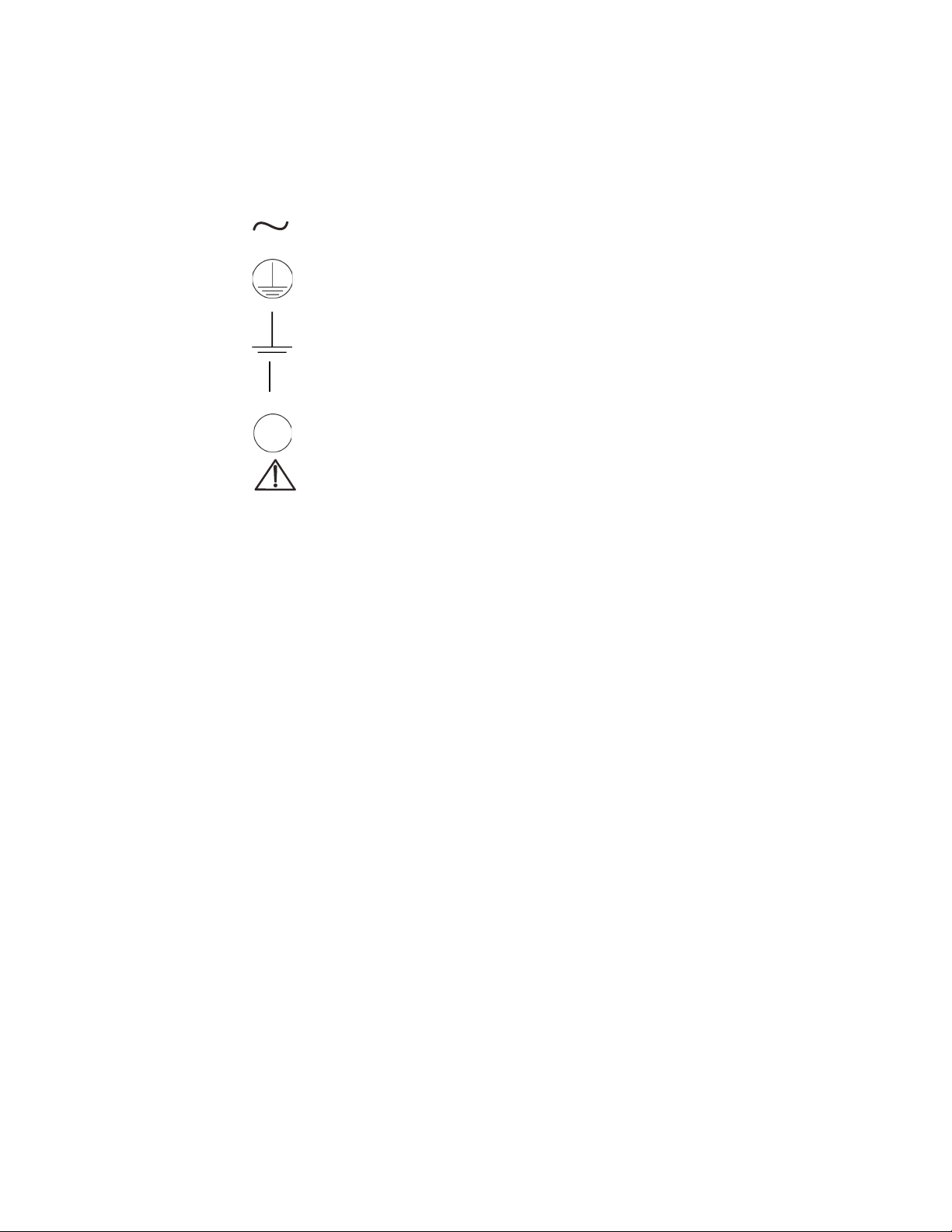
These symbols appear on the Dionex Aquion RFIC or on labels affixed to the system:
Alternating current
Primary protective conductor terminal
Secondary protective conductor terminal
Power supply is on
Power supply is off
Indicates a potential hazard. Refer to this manual for an explanation of the
hazard and how to proceed.
Regulatory Compliance
Thermo Fisher Scientific performs complete testing and evaluation of its products to ensure
full compliance with applicable domestic and international regulations. When the system is
delivered to you, it meets all pertinent electromagnetic compatibility (EMC) and safety
standards as described in this section.
Changes that you make to your system may void compliance with one or more of these EMC
and safety standards. Changes to your system include replacing a part or adding components,
options, or peripherals not specifically authorized and qualified by Thermo Fisher Scientific.
To ensure continued compliance with EMC and safety standards, replacement parts and
additional components, options, and peripherals must be ordered from Thermo Fisher
Scientific or one of its authorized representatives.
The regulatory symbols on the Dionex Aquion RFIC model/data label indicate that the
system is in compliance with the following EMC and safety standards:
• EN 61010-1:2010
• UL 61010-1:2012
• CAN/CSA-C22.2 No. 61010-1-12
• EN 61326-1:2013
The CE mark on the Dionex Aquion RFIC model/data label indicates that the system is in
compliance with the following European Community Directives as is evidenced by
compliance to the associated standard where appropriate:
• Low Voltage/Safety Directive: 2014/35/EU by conforming to EN61010-1:2013
Thermo Scientific Dionex Aquion RFIC Operator’s Manual vii
Page 10

Preface
• EMC Directive: 2014/30/EU by conforming to EN61326-1:2013
Notice on Lifting and Handling of Thermo Scientific Instruments
For your safety, and in compliance with international regulations, the physical handling of
this Thermo Fisher Scientific instrument requires a team effort to lift and/or move the
instrument. This instrument is too heavy and/or bulky for one person alone to handle safely.
Notice on the Proper Use of Thermo Scientific Instruments
In compliance with international regulations: This instrument must be used in the manner
specified by Thermo Fisher Scientific to ensure protections provided by the instrument are
not impaired. Deviations from specified instructions on the proper use of the instrument
include changes to the system and parts replacement. Accordingly, order replacement parts
from Thermo Fisher Scientific or one of its authorized representatives.
Notice on the Susceptibility to Electromagnetic Transmission
WEEE Compliance
Your instrument is designed to work in a controlled electromagnetic environment. Do not use
radio frequency transmitters, such as mobile phones, in close proximity to the instrument.
For manufacturing location, see the label on the instrument.
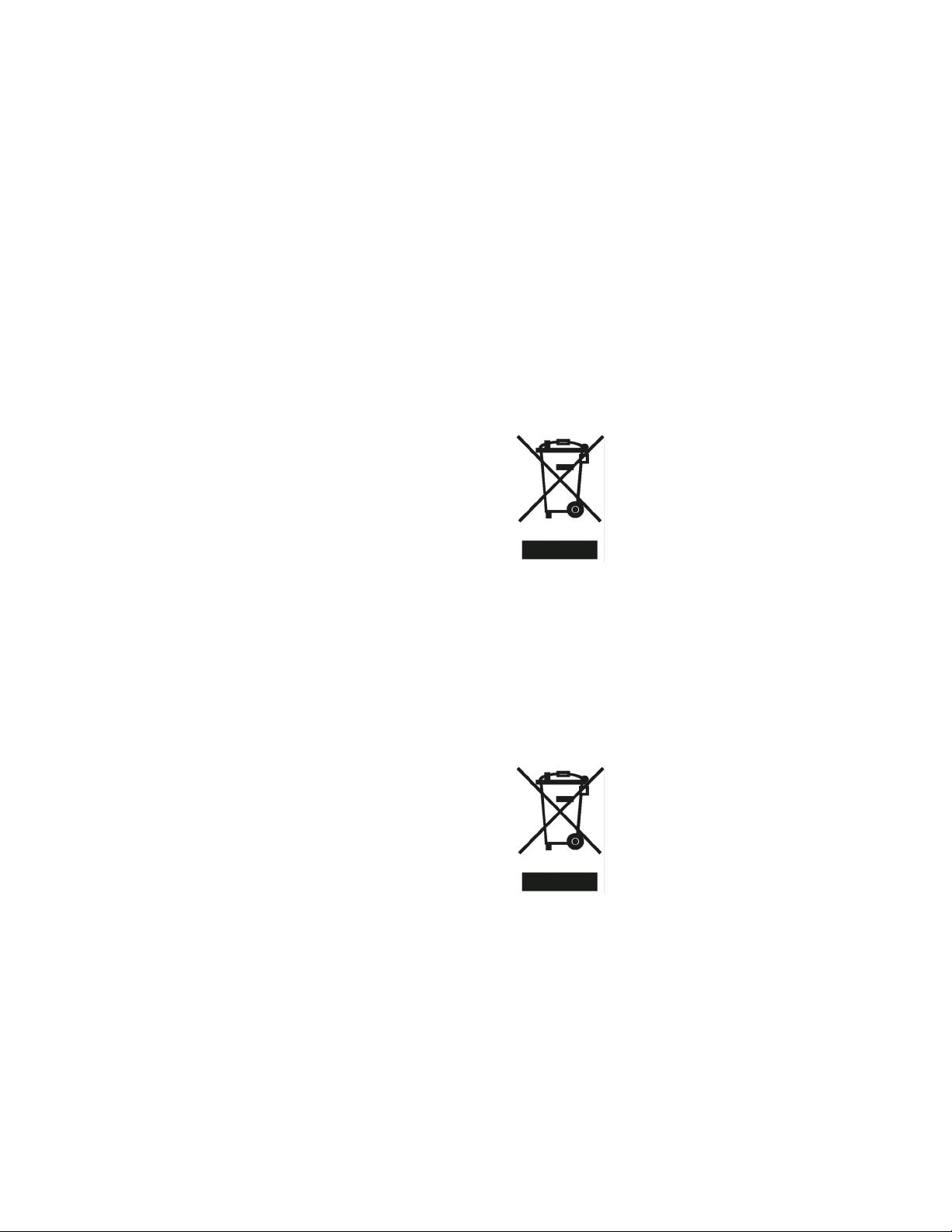
This product complies with the European Union’s Waste Electrical & Electronic Equipment
(WEEE) Directive 2002/96/EC. It is marked with the following symbol:
Thermo Fisher Scientific is registered with B2B Compliance (B2Bcompliance.org.uk) in the
UK and with the European Recycling Platform (ERP-recycling.org) in all other countries of
the European Union and in Norway.
If this product is located in Europe and you want to participate in the Thermo Fisher
Scientific B2B (Business-to-Business) Recycling Program, send an email request to
weee.recycle@thermofisher.com with the following information:
• WEEE product class
• Name of the manufacturer or distributor (where you purchased the product)
• Number of product pieces, and the estimated total weight and volume
viii Dionex Aquion RFIC Operator’s Manual Thermo Scientific
Page 11
Conformité DEEE
Preface
• Pick-up address and contact person (including contact information)
• Appropriate pick-up time
• Declaration of decontamination, stating that all hazardous fluids or material have been
removed from the product
For additional information about the Restriction on Hazardous Substances (RoHS) Directive
for the European Union, search for RoHS on the Thermo Fisher Scientific European language
websites.
Ce produit est conforme avec la directive européenne (2002/96/EC) des Déchets
d'Equipements Electriques et Electroniques (DEEE). Il est marqué par le symbole suivant:
WEEE Konformität
Thermo Fisher Scientific s'est associé avec une ou plusieurs sociétés de recyclage dans chaque
état membre de l’Union Européenne et ce produit devrait être collecté ou recyclé par
celle(s)-ci. Pour davantage d'informations, rendez-vous sur la page
www.thermoscientific.fr/rohs.
Dieses Produkt entspricht der EU Waste Electrical & Electronic Equipment (WEEE)
Richtlinie 2002/96/EC. Es ist mit dem folgenden Symbol gekennzeichnet:
Thermo Fisher Scientific hat Vereinbarungen mit Verwertungs-/Entsorgungsfirmen in allen
EU-Mitgliedsstaaten getroffen, damit dieses Produkt durch diese Firmen wiederverwertet
oder entsorgt werden kann. Weitere Informationen finden Sie unter
www.thermoscientific.de/rohs.
Thermo Scientific Dionex Aquion RFIC Operator’s Manual ix
Page 12

Preface
Deionized Water Requirements for IC
For electrolytic eluent generation, or when manually preparing eluent and regenerant, use
ASTM Type I (18 megohm-cm) filtered and deionized water that meets the specifications
listed in Ta bl e 1 .
.
Table 1. ASTM filtered, Type I deionized water specifications for ion chromatography
Contaminant Specification
Ions–Resistivity >18.0 megohm-cm
Organics–TOC <10 ppb
Iron/Transition Metals* <1 ppb
Pyrogens <0.03 (Eu/mL)
Particulates > 0.2 μm <1 (units/mL)
Colloids–Silica <10 ppb
Bacteria <1 (cfu/mL)
Contacting Us
* Iron/transition metal content not specified for ASTM Type I water
For Technical Support for Dionex products
In the U.S. and Canada, call 1-800-532-4752.
Outside the U.S. and Canada, call the nearest Thermo Fisher Scientific office.
For additional contact information
Go to www.thermofisher.com/us/en/home/technical-resources/contact-us.html.
x Dionex Aquion RFIC Operator’s Manual Thermo Scientific
Page 13

Risque de choc électrique : l’instrument utilise des
tensions susceptibles de provoquer une électrocution
et/ou des blessures corporelles. Il doit être arrêté et
Riesgo de descargas eléctricas: Este instrumento
utiliza voltajes que pueden causar descargas
eléctricas y/o lesiones personales. Antes de revisar o
débranché de la source de courant avant toute
intervention. Ne pas utiliser l’instrument sans ses
couvercles. Ne pas enlever les capots de protection des
cartes à circuit imprimé (PCBA).
reparar el instrumento, apáguelo y desconéctelo de la
red eléctrica. Mantenga colocadas las cubiertas
mientras se utiliza el instrumento. No retire las
cubiertas protectoras del circuito impreso completo
(PCBA).
Danger lié aux produits chimiques : porter des gants
et d’autres équipements de protection appropriés pour
manipuler les produits chimiques toxiques, cancérigènes,
mutagènes, corrosifs ou irritants. Utiliser des récipients
homologués et des procédures adéquates pour la mise au
Peligro por sustancias químicas: Cuando
manipule sustancias químicas, tóxicas,
carcinogénicas, mutágenas, corrosivas o irritantes,
utilice guantes y otro equipo de protección. Utilice
siempre recipientes homologados y siga los
rebut des huiles usagées et lors de la manipulation des
pièces de l’instrument en contact avec l’eau.
procedimientos adecuados cuando deseche aceite
residual o manipule partes mojadas del instrumento.
Surface chaude : laisser refroidir les composants
chauffés avant toute manipulation.
Superficies calientes: Antes de tocar los
componentes calientes, espere a que se enfríen.
Danger lié aux substances inflammables : agir avec
précaution lors de l’utilisation du système en présence de
substances inflammables.
Peligro por sustancias inflamables: Tenga mucho
cuidado cuando utilice el sistema cerca de sustancias
inflamables.
Risque de lésion oculaire : les projections chimiques,
les particules en suspension dans l’air et les objets
tranchants peuvent entraîner des lésions oculaires. (Les
objets tranchants pouvant être installés par les clients
dans l’instrument comprennent les tubes en silice fondue,
les aiguilles du passeur automatique, etc.). Porter des
lunettes de protection lors de toute manipulation de
produit chimique ou intervention sur l’instrument.
Danger d’ordre général : indique la présence d’un
Riesgo de lesiones oculares: Las salpicaduras de
sustancias químicas, las partículas flotantes en el
aire y los objetos afilados pueden causar lesiones
oculares. (Entre los objetos afilados que los clientes
pueden instalar en el instrumento se encuentran
tubos de sílice fundida, agujas del muestreador
automático, etc.). Para manipular sustancias
químicas o realizar tareas de mantenimiento, utilice
gafas de seguridad.
Peligro general: Existen peligros que no se incluyen
risque n’appartenant pas aux catégories citées plus haut.
Ce symbole figure également sur l’instrument. Pour plus
de détails sur ce danger potentiel, se reporter au manuel
de l’instrument.
Si la sûreté d’une procédure est incertaine, contacter
l’assistance technique pour les produits Thermo Scientific
Sunnyvale.
en las otras categorías. Este símbolo también
aparece en el instrumento. Si desea obtener más
información sobre estos peligros, consulte el manual
del instrumento.
En caso de duda sobre la seguridad de un procedimiento,
póngase en contacto con el personal de servicio técnico
de los productos Thermo Scientific Sunnyvale.
CAUTION Symbol CAUTION VORSICHT PRECAUCIÓN MISE EN GARDE
Stromschlaggefahr: Dieses Gerät arbeitet mit
Spannungen, die Stromschläge und/oder
Personenverletzungen verursachen können. Vor
Risk electric shock: This instrument uses
voltages that can cause electric shock and/or
personal injury. Before servicing, shut down the
Wartungsarbeiten muss das Gerät abgeschaltet
und vom Netz getrennt werden. Betreiben Sie das
Gerät nicht mit abgenommenen Abdeckungen.
Nehmen Sie die Schutzabdeckungen von
instrument and disconnect it from line power.
While operating the instrument, keep covers on.
Do not remove the protective covers from the
printed circuit board assemblies (PCBAs).
Leiterplatten nicht ab.
Gefahr durch Chemikalien: Tragen Sie beim
Chemical hazard: Wear gloves and other
Umgang mit toxischen, karzinogenen, mutagenen,
ätzenden oder reizenden Chemikalien
Schutzhandschuhe und weitere geeignete
Schutzausrüstung. Verwenden Sie bei der
Entsorgung von verbrauchtem Öl und beim Umgang
mit medienberührenden Komponenten die
vorgeschriebenen Behälter, und wenden Sie
protective equipment, as appropriate, when
handling toxic, carcinogenic, mutagenic, corrosive,
or irritant chemicals. Use approved containers and
proper procedures to dispose of waste oil and
when handling wetted parts of the instrument.
ordnungsgemäße Verfahren an.
Heiße Oberflächen: Lassen Sie heiße
Komponenten vor der Berührung abkühlen.
Hot surface: Before touching, allow any heated
components to cool.
Gefahr durch entzündbare Substanzen:
Beachten Sie die einschlägigen Vorsichtsmaßnahmen,
Flammable substances hazard: Use care when
operating the system in the presence of flammable
wenn Sie das System in Gegenwart von entzündbaren
substances.
Umgang mit Chemikalien oder bei der Wartung des
Gerätes eine Schutzbrille.
Allgemeine Gefahr: Es besteht eine weitere
Gefahr, die nicht in den vorstehenden Kategorien
beschrieben ist. Dieses Symbol wird auch auf dem
Gerät angebracht. Einzelheiten zu dieser Gefahr
finden Sie in den Gerätehandbüchern.
Wenn Sie sich über die Sicherheit eines Verfahrens
im Unklaren sind, setzen Sie sich, bevor Sie
fortfahren, mit dem technischen Support für
Thermo Scientific Sunnyvale Produkte in
Substanzen betreiben.
Augenverletzungsrisiko: Verspritzte
Chemikalien, Schwebstoffpartikel oder scharfe
Objekte können Augenverletzungen verursachen.
(Scharfe Objekte, die Kunden möglicherweise im
Gerät installieren, sind z. B. Quarzglas-Kapillaren,
die Nadel des Autosamplers, usw.) Tragen Sie beim
General hazard: A hazard is present that is not
included in the other categories. This symbol also
appears on the instrument. For details about the
hazard, refer to the instrument manual.
When the safety of a procedure is questionable,
Risk of eye injury: Eye injury could occur from
splattered chemicals, airborne particles, or sharp
objects. (Sharp objects that customers might install
in the instrument include fused-silica tubing, the
autosampler needle, and so on.) Wear safety
glasses when handling chemicals or servicing the
instrument.
contact Technical Support for Thermo Scientific
Verbindung.
Sunnyvale products.
Page 14

Danger lié au laser : l’instrument utilise un laser
Peligro por láser: Este instrumento utiliza un láser
susceptible de provoquer des blessures corporelles. Ce
que puede producir lesiones personales. Este símbolo
symbole figure également sur l’instrument. Pour plus de
también aparece en el instrumento. Si desea obtener
détails sur ce danger potentiel, se reporter au manuel de
más información sobre el peligro, consulte el manual
l’instrument.
Danger lié aux rayons ultraviolets : ne jamais
del instrumento.
Peligro por luz ultravioleta: No mire directamente
regarder directement la lumière ultraviolette (UV) ou la
source d’UV. Une exposition peut entraîner des lésions
a una luz ultravioleta (UV) ni a una fuente UV. La
exposición puede causar daños oculares. Lleve
Si la sûreté d’une procédure est incertaine, contacter
l’assistance technique pour les produits Thermo Scientific
En caso de duda sobre la seguridad de un pro cedimiento,
póngase en contacto con el personal de servicio técnico
Sunnyvale.
de los productos Thermo Scientific Sunnyvale.
oculaires. Porter des protections oculaires anti-UV.
Objet tranchant : éviter tout contact physique avec
l’objet.
protección ocular para UV.
Objeto puntiagudo: Evite el contacto físico con el
objeto.
Risque de pincement : éloigner les mains de cette zone.
Puntos de pinzamiento: Mantenga las manos
apartadas de esta área.
Objet lourd : ne jamais soulever ou déplacer l’instrument
seul sous peine de blessure corporelle ou
d’endommagement de l’instrument. Pour obtenir des
instructions de levage spécifiques, se reporter au manuel
de l’instrument.
Risque de trébuchement : faire attention aux câbles,
Objeto pesado: Nunca levante ni mueva el
instrumento por su cuenta, podría sufrir lesiones
personales o dañar el equipo. Para obtener
instrucciones específicas sobre levantamiento,
consulte el manual del instrumento.
Tropiezo con obstáculos: Tenga en cuenta los cables,
tuyaux et autres objets situés sur le sol.
mangueras u otros objetos colocados en el suelo.
CAUTION Symbol CAUTION VORSICHT PRECAUCIÓN MISE EN GARDE
Gefahr durch Laserstrahlen: Der in diesem Gerät
verwendete Laser kann zu Verletzungen führen.
Laser hazard: This instrument uses a laser that is
capable of causing personal injury. This symbol
Dieses Symbol wird auch auf dem Gerät
also appears on the instrument. For details about
angebracht. Einzelheiten zu dieser Gefahr finden
Sie in den Gerätehandbüchern.
Gefahr durch UV-Licht: Richten Sie Ihren Blick
nicht direkt auf ultraviolettes Licht (UV-Licht) oder
in die UV-Quelle. Dies kann zu Augenschäden
the hazard, refer to the instrument manual.
Ultra violet light hazard: Do not look directly at
the ultra-violet (UV) light or into the UV source.
Exposure can cause eye damage. Wear UV eye
führen. Tragen Sie eine UV-Schutzbrille.
protection.
Scharfes Objekt: Vermeiden Sie den physischen
Kontakt mit dem Objekt.
Sharp object: Avoid physical contact with the
object.
Bereich fern.
Pinch point: Keep hands away from this area. Quetschgefahr: Halten Sie Ihre Hände von diesem
Schweres Objekt: Bewegen und heben Sie das
Gerät niemals allein an; dies kann zu Verletzungen
oder zur Beschädigung des Geräts führen.
Spezifische Anweisungen zum Anheben finden Sie
im Gerätehandbuch.
Stolpergefahr: Achten Sie auf Kabel, Schläuche
und andere Objekte auf dem Fußboden.
Heavy objects: Never lift or move the instrument
by yourself; you can suffer personal injury or
damage the equipment. For specific lifting
instructions, refer to the instrument manual.
Trip obstacle: Be aware of cords, hoses, or other
objects located on the floor.
fortfahren, mit Ihrer lokalen technischen
Unterstützungsorganisation für Thermo Scientific
Wenn Sie sich über die Sicherheit eines Verfahrens
im unklaren sind, setzen Sie sich, bevor Sie
When the safety of a procedure is questionable,
contact Technical Support for Thermo Scientific
Sunnyvale Produkte in Verbindung.
Sunnyvale products.
Page 15

普通危险:未归入其他类别的危险。此符号也会在仪器上出现。有关此
危险的详细信息,参阅适当的仪器手册。若对任何步骤的安全事项有疑
触电危险:本仪器所用电压可能导致电击或人身伤害。进行维修服务
前,务必关闭仪器电源并断开其电源连接。操作此仪器时,不要卸下
顶盖。勿卸下印刷电路板组件 (PCBA)的保护盖。
化学品危险:当处理毒性、致癌性、致突变性、腐蚀性或者刺激性化学
品时,佩戴手套和其他保护性设备。当处理浸湿的仪器部件以及废油
时,使用认可的容器和合适的步骤。
易燃物危险:在有易燃物质的场地操作该系统时,务必小心谨慎。
眼睛伤害风险:眼睛受伤可能源自飞溅的化学品、空气中的颗粒,
或者锋利的物体。(安装在仪器内的锋利物体包括熔融石英管、
自动进样器的进样针等。)处理化学品或对仪器进行维修服务时,
务必戴上防护眼镜。
问,联系 Thermo Scientific Sunnyvale 产品的技术支持中心。
警告 危险警告
CAUTION Symbol CAUTION
Risk electric shock: This instrument
感電の危険性 : この機器では、感電および / または身体傷害を引き起こ
uses voltages that can cause electric
すおそれのある電圧を使用しています。整備点検の前には、機器の電
shock and/or personal injury. Before
源を切り、電源コードを抜いてください。機器の作動中は、カバーを
付けたままにしてください。プリント基板アセンブリ (PCBA) から保護
カバーを取り外さないでください。
servicing, shut down the instrument and
disconnect it from line power. While
operating the instrument, keep covers on.
Do not remove the protective covers from
the printed circuit board assemblies
(PCBAs).
化学的危険性 : 毒性、発癌性、変異原性、腐食性、または刺激性のある
化学薬品を取り扱うときは、必要に応じて手袋などの保護具を着用し
ます。廃油を処分したり、機器の接液部品を取り扱うときは、認可さ
れた容器を使用し、適切な手順に従います。
Chemical hazard: Wear gloves and
other protective equipment, as
appropriate, when handling toxic,
carcinogenic, mutagenic, corrosive, or
高温面 : 触れる前に、加熱した部品を冷ましてください。 热表面:待高温部件冷却之后再进行维修。
irritant chemicals. Use approved
containers and proper procedures to
dispose of waste oil and when handling
wetted parts of the instrument.
Hot surface: Before touching, allow any
heated components to cool.
可燃性物質の危険性 : 可燃性物質があるところでシステムを作動させる
Flammable substances hazard: Use
care when operating the system in the
場合は十分注意してください。
presence of flammable substances.
ては、機器のマニュアルを参照してください。
手順の安全性にご不明な点がある場合は、Thermo Scientific Sunnyvale 製品の
眼外傷の危険性 : 飛散した化学薬品、浮遊粒子、または鋭利な物体に
よって眼外傷を負うおそれがあります (機器に取り付けられる可能性が
ある鋭利な物体は、ヒューズドシリカ、オートサンプラーニードルな
どです )。化学薬品を取り扱ったり、機器を整備点検するときは、保護
メガネを着用します。
Risk of eye injury: Eye injury could occur
from splattered chemicals, airborne
particles, or sharp objects. (Sharp objects
that customers might install in the
instrument include fused-silica tubing, the
autosampler needle, and so on.) Wear
一般的な危険性 : それぞれのカテゴリーに当てはまらない危険がありま
safety glasses when handling chemicals
or servicing the instrument.
General hazard: A hazard is present that
テクニカルサポートまでお問い合わせください。
す。この標識記号は機器にも表示されています。この危険の詳細につい
is not included in the other categories.
This symbol also appears on the
instrument. For details about the hazard,
refer to the instrument manual.
When the safety of a procedure is
questionable, contact Technical Support
for Thermo Scientific Sunnyvale products.
Page 16

警告 危险警告
激光危险:本仪器所用激光会导致人身伤害。此符号也会在仪器上出
レーザー光線の危険性 : この機器では、身体傷害を引き起こすおそれ
现。有关此危险的详细信息,参阅适当的仪器手册。
のあるレーザーを使用しています。この標識記号は機器にも表示され
ています。この危険の詳細については、機器のマニュアルを参照して
ください。
紫外光危险:不要直视紫外 (UV)光或者紫外光源。直视可能导致眼
睛伤害。佩戴紫外线防护眼镜。
紫外光の危険性 : 紫外 (UV) 光または UV 光源を直接見ないでください。照
射によって眼損傷を引き起こすおそれがあります。UV 保護メガネを着用
重物:切勿独自提起或移动本仪器;可能遭受人身伤害或损坏仪器。
有关具体的提起说明,参阅仪器手册。
します。
鋭利な物体 : 物体との身体的接触を避けてください。 锋利物体:避免直接接触锋利的物体。
ピンチポイント : この部分には手を挟まれないようにしてください。 夹点:勿将手放在此部位。
重量物 :1 人で機器を持ち上げたり移動しないでください。身体傷害を
負ったり、機器を損傷するおそれがあります。具体的な持ち上げ方法
については、機器のマニュアルを参照してください。
绊倒危险:注意地面上的线、管或其他物品。
作業の障害物 : 床にあるコード、ホース、その他の物体に注意してく
如对安全程序有疑问,联系 Thermo Scientific Sunnyvale 产品的技术支持
中心。
ださい。
手順の安全性にご不明な点がある場合は、Thermo Scientific Sunnyvale 製品の
テクニカルサポートまでお問い合わせください。
Laser hazard: This instrument uses a
laser that is capable of causing personal
injury. This symbol also appears on the
instrument. For details about the hazard,
refer to the instrument manual.
Ultra violet light hazard: Do not look
directly at the ultra-violet (UV) light or into
the UV source. Exposure can cause eye
damage. Wear UV eye protection.
Sharp object: Avoid physical contact
with the object.
CAUTION Symbol CAUTION
Pinch point: Keep hands away from this
area.
Heavy objects: Never lift or move the
instrument by yourself; you can suffer
personal injury or damage the equipment.
For specific lifting instructions, refer to the
instrument manual.
Trip obstacle: Be aware of cords, hoses,
or other objects located on the floor.
When the safety of a procedure is
questionable, contact Technical Support
for Thermo Scientific Sunnyvale products.
Page 17
1
Introduction
Eluent
Separator
column
Waste
Guard column
(optional)
Injection valve
2. Sample injection
1. Eluent delivery
3. Separation
4. Detection
5. Data analysis
Cell
Suppressor
(optional)
Pump
Waste
Sample
P
L
S
W
C
L
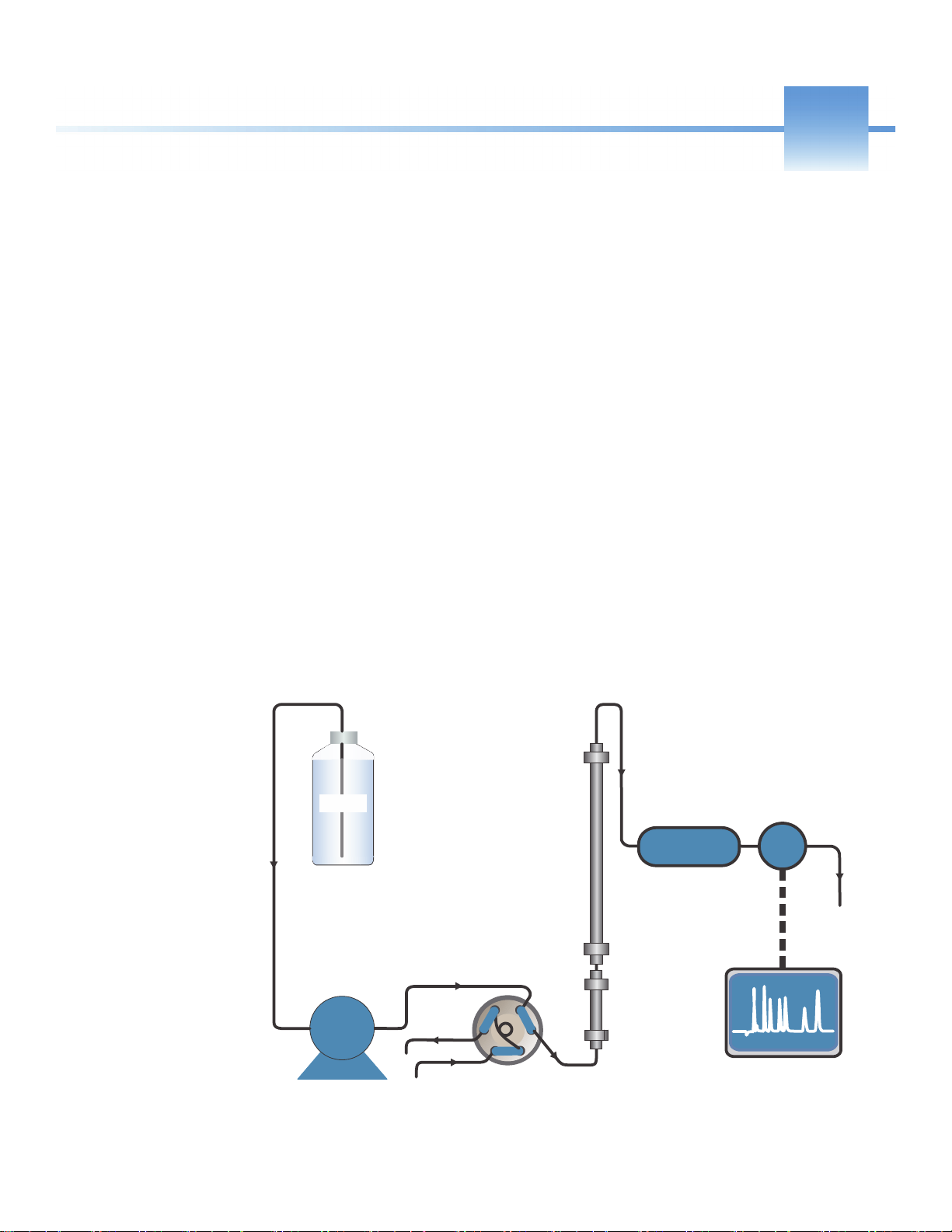
Introduction to Ion Chromatography (IC)
The Dionex Aquion RFIC performs ion analyses using suppressed or non-suppressed
conductivity detection. An ion chromatography system typically consists of a liquid eluent, a
high-pressure pump, a sample injector, a guard and separator column, a chemical suppressor, a
conductivity cell, and a data collection system.
Before running a sample, the ion chromatography system is calibrated using a standard
solution. By comparing the data obtained from a sample to that obtained from the known
standard, sample ions can be identified and quantitated. The data collection system, typically
a computer running chromatography software, produces a chromatogram (a plot of the
detector output vs. time). The chromatography software converts each peak in the
chromatogram to a sample concentration and produces a printout of the results. A typical IC
analysis consists of six stages (see Figure 1).
Figure 1. Ion process analysis
Thermo Scientific Dionex Aquion RFIC Operator’s Manual 1
Page 18

1
Introduction
Introduction to Ion Chromatography (IC)
1. Eluent Delivery
2. Sample Injection
• Eluent, a liquid that helps to separate the sample ions, carries the sample through the
ion chromatography system. The Dionex Aquion RFIC includes an eluent generator,
which generates eluent online from deionized water.
• The system can operate in two eluent delivery modes. In isocratic mode, the eluent
composition and concentration remain constant throughout the run. In the one-step
gradient mode, the eluent concentration changes over time. The delivery mode is
defined in the Chromeleon Instrument Method Wizard. For more information, refer
to the Chromeleon Help.
• The liquid sample is loaded into a sample loop manually or automatically (if an
automated sampler is installed). When triggered, the Dionex Aquion RFIC injects
the sample into the eluent stream.
• The pump pushes the eluent and sample through the guard and separator columns
(chemically-inert tubes packed with a polymeric resin). The guard column removes
contaminants that might poison the separator column.
3. Separation
• As the eluent and sample are pumped through the separator column, the sample ions
are separated. In the Dionex Aquion RFIC, the mode of separation is called ion
exchange. This is based on the premise that different sample ions migrate through the
IC column at different rates, depending upon their interactions with the ion
exchange sites.
4. Suppression
• After the eluent and sample ions leave the column, they flow through a suppressor
that selectively enhances detection of the sample ions while suppressing the
conductivity of the eluent.
5. Detection
• A conductivity cell measures the electrical conductance of the sample ions as they
emerge from the suppressor and produces a signal based on a chemical or physical
property of the analyte.
6. Data Analysis
• The conductivity cell transmits the signal to a data collection system.
• The data collection system (for the Dionex Aquion RFIC, this is the Chromeleon 7
Chromatography Data System) identifies the ions based on retention time, and
quantifies each analyte by integrating the peak area or peak height. The data is
quantitated by comparing the sample peaks in a chromatogram to those produced
from a standard solution. The results are displayed as a chromatogram and the
concentrations of ionic analytes can be automatically determined and tabulated.
2 Dionex Aquion RFIC Operator’s Manual Thermo Scientific
Page 19

Overview of the Dionex Aquion RFIC
The Dionex Aquion RFIC is an integrated ion chromatography system containing an eluent
generator, pump, injection valve, and conductivity detector. Other system components,
including a guard column, separator column, and suppressor vary, depending on the analyses
to be performed.
If necessary, the Dionex Aquion RFIC can be configured with a column heater for
temperature control of the column.
Dionex Aquion RFIC operation is controlled remotely by a personal computer running the
Microsoft® Windows® 10, Windows 8.1, or Windows 7 operating system and Chromeleon
software (version 7.2.9 DUa or later). Chromeleon also provides data acquisition and data
processing functions.
For communication with Chromeleon, the Dionex Aquion RFIC must be connected to a
USB (Universal Serial Bus) port on the computer or a USB hub. For details, refer to the
Dionex Aquion RFIC installation instructions.
1
Introduction
Overview of the Dionex Aquion RFIC
Thermo Scientific Dionex Aquion RFIC Operator’s Manual 3
Page 20

1
Introduction
Overview of the Dionex Aquion RFIC
4 Dionex Aquion RFIC Operator’s Manual Thermo Scientific
Page 21

2
Description
This chapter describes key features of the Dionex Aquion RFIC and introduces the
Chromeleon user interface.
Contents
• Operating Features
• Flow Schematics
• Chromeleon Chromatography Data System
• System Component Details
Thermo Scientific Dionex Aquion RFIC Operator’s Manual 5
Page 22
2
Status LEDs
Power LED
Injection port
Description
Operating Features
Operating Features
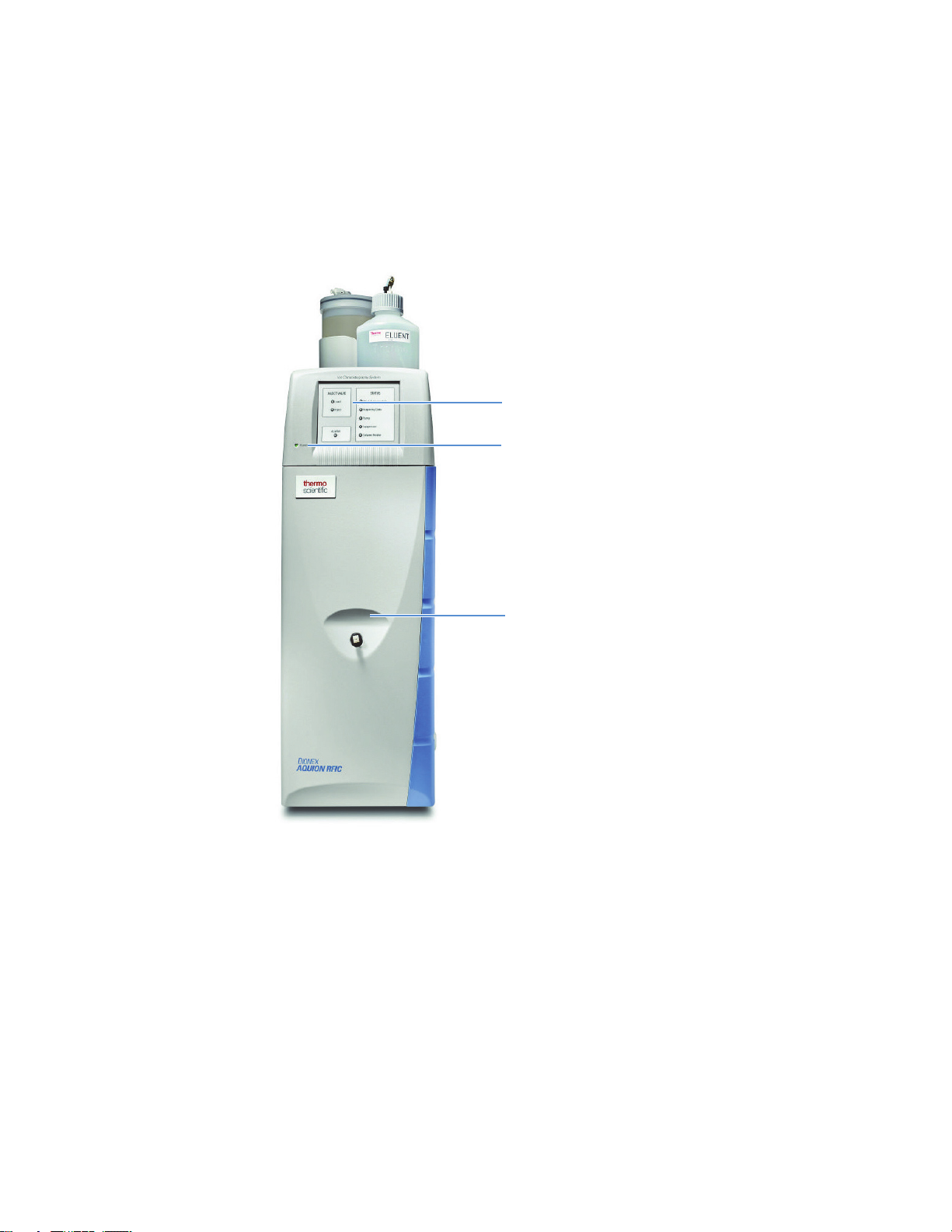
Front Panel
Figure 2. Dionex Aquion RFIC front panel
Injection Port
The sample to be analyzed can be injected manually into the injection port, using a syringe.
For automated sample injection, the Dionex Aquion RFIC must be connected to an
autosampler. For more information about sample injection, see “Operation Overview” on
page 32.
LEDs
The Power LED indicates whether the Dionex Aquion RFIC power is on. Other LEDs
indicate the status of various system functions. For details, see Tab le 2 .
6 Dionex Aquion RFIC Operator’s Manual Thermo Scientific
Page 23
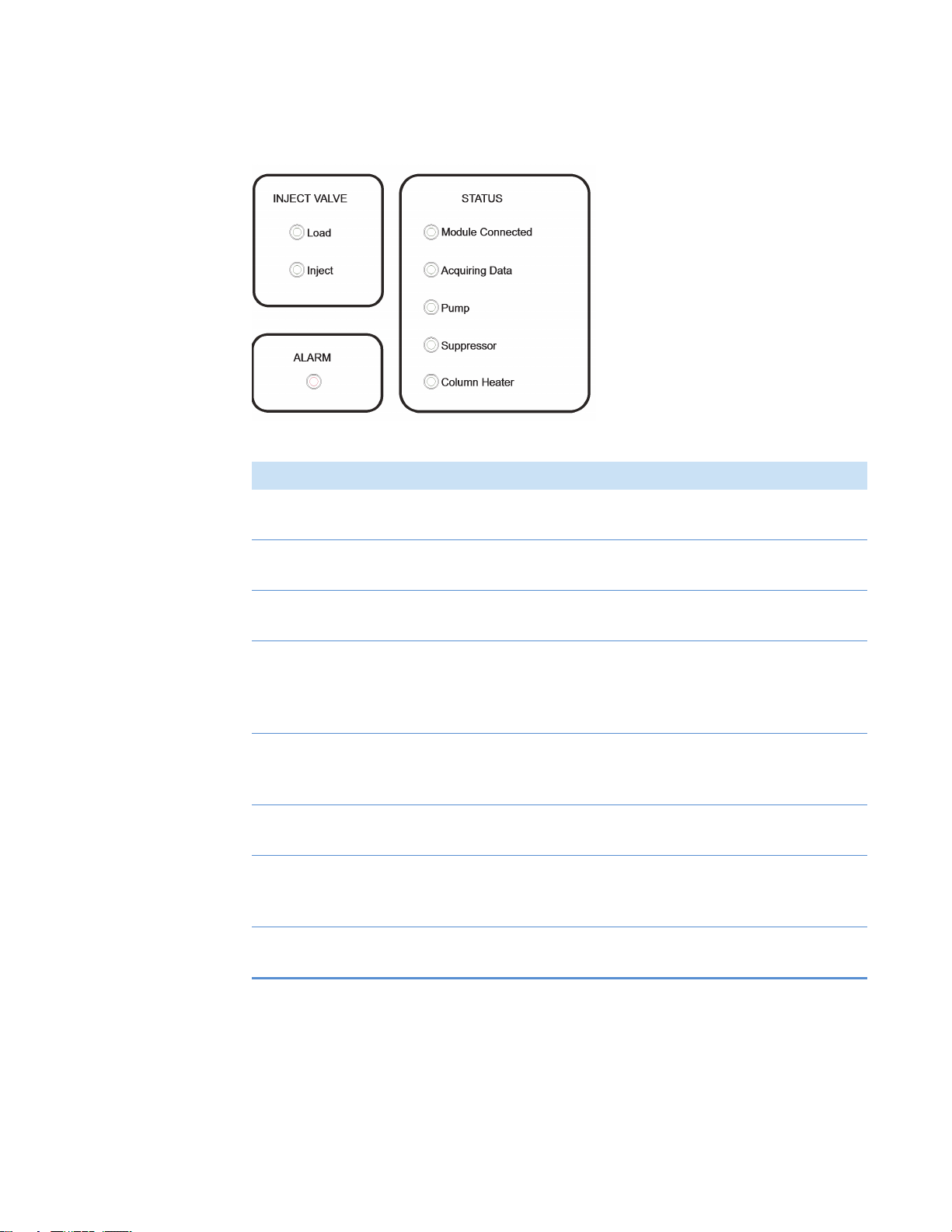
Figure 3. Dionex Aquion RFIC front panel LEDs
Table 2. Dionex Aquion RFIC front panel LED states
LED label If on (green) If flashing
2
Description
Operating Features
Load Injection valve is in
Valve error detected
Load position
Inject Injection valve is in
Valve error detected
Inject position
Alarm LED has no “on”
(green) state
Module Connected Dionex Aquion
Error detected; check the Chromeleon audit
trail for the cause
LED does not flash
RFIC is connected
to a Chromeleon
instrument
Acquiring Data Sequence or manual
data acquisition is in
Sequence stopped because an error was
detected
progress
Pump Pump is on High or low pressure limit exceeded (pump is
turned off)
Suppressor Suppressor is on and
current is being
applied to it
Column Heater Column heater is at
set temperature
Continuity check failed, or suppressor is over
the voltage, current, or power limit
(suppressor is turned off)
Column heater is transitioning to new
temperature
Thermo Scientific Dionex Aquion RFIC Operator’s Manual 7
Page 24
2
EGC service area
EGC and CR-TC power
supply connectors
EGC holder
Tubing chase
(under connectors)
Deionized
water
EGC
Description
Operating Features
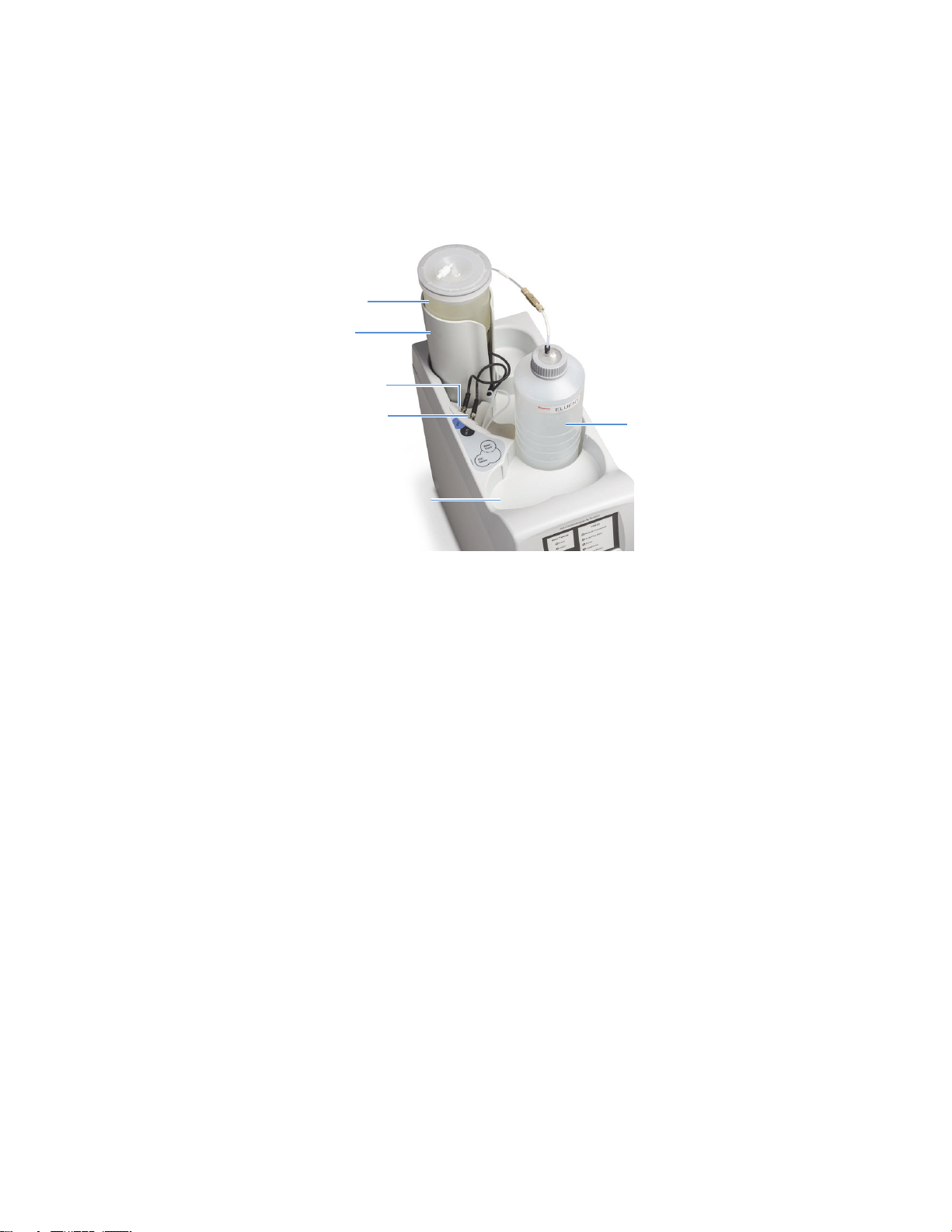
Top Cover
Figure 4 shows the top cover of the Dionex Aquion RFIC.
Figure 4. Dionex Aquion RFIC top cover
• Storage area for eluent generator cartridge and eluent reservoirs
– The Dionex EGC (eluent generator cartridge) is installed in a holder that fits into the
rear of the storage area. For more information about the Dionex EGC, see page 23.
– Up to three 2-L plastic reservoirs (P/N 046548) or one 4-L plastic reservoir
(P/N 039164) can be installed in the storage area.
• Power supply connectors
– The electrical cable from the Dionex EGC connects to the EGC connector.
– The electrical cable from the Thermo Scientific™ Dionex™
Continuously Regenerated
Trap Column connects to the CR-TC connector. For more information about the
Dionex CR-TC, see page 25.
– The tubing chase under the connectors routes tubing from the eluent reservoir and
Dionex EGC holder to the front of the Dionex Aquion RFIC.
• Dionex EGC service area
– The service area holds the Dionex EGC during installation and replacement.
8 Dionex Aquion RFIC Operator’s Manual Thermo Scientific
Page 25
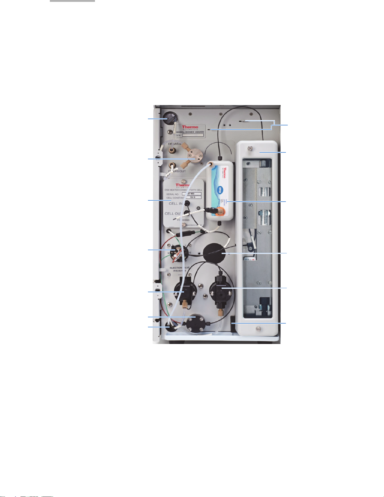
Component Panel
Mounting brackets for
second suppressor
Tubing chase
Column heater
(optional)
Eluent valve
Suppressor
DS6 conductivity cell
Injection valve
Tubing chase
Pump head
Pressure transducer
Leak sensor
Pump head
Site for auxiliary valve
(optional)
2
Description
Operating Features
Figure 5 shows the user-accessible components installed on the component panel behind the
Dionex Aquion RFIC front door.
Figure 5. Dionex Aquion RFIC component panel
Pressure Transducer
Leak Sensor
The pressure transducer measures the system backpressure.
A leak sensor is installed in the drip tray at the bottom of the component panel. If liquid
accumulates in the tray, the front panel Alarm LED flashes and an error message is logged in
the Chromeleon audit trail.
Thermo Scientific Dionex Aquion RFIC Operator’s Manual 9
Page 26

2
Description
Operating Features
Pump Heads
The Dionex Aquion RFIC includes a dual-piston serial pump. The flow rate can be set to
0.00 mL/min or to between 0.05 and 5.00 mL/min. For optimum performance, set the flow
rate to between 0.40 and 2.00 mL/min. Setting the flow rate to 0.00 mL/min turns off the
pump. For more information, see “Pump” on page 21.
Injection Valve
The injection valve is a 6-port, electrically-activated Rheodyne™ valve. A 25-μL sample loop
(P/N 042857) is installed on the valve at the factory. For more information, see “Injection
Valv e” on page 25.
Auxiliary Valve (Optional)
The auxiliary valve is a 2-position, electrically-activated Rheodyne valve. The valve is available
in 6-port and 10-port models. For more information, see “Auxiliary Valve (Optional)” on
page 26.
DS6 Heated Conductivity Cell
The flow-through conductivity cell measures the electrical conductance of analyte ions as they
pass through the cell. A heat exchanger inside the cell regulates the temperature, which can be
set to between 30 and 55 °C. For optimum performance, set the temperature to at least 7 °C
above the ambient temperature and 5 °C above the column oven temperature. For more
information, see “DS6 Heated Conductivity Cell” on page 10.
Suppressor
The suppressor reduces the eluent conductivity and enhances the conductivity of the sample
ions, thereby increasing detection sensitivity. The following suppressors can be used with the
Dionex Aquion RFIC:
• Thermo Scientific™ Dionex™ DRS™ Dynamically Regenerated Suppressor
• Thermo Scientific™ Dionex™ ERS™ 500 Electrolytically Regenerated Suppressor
For more information, see “Suppressor” on page 28.
Separator and Guard Columns
Both the separator and guard columns are packed with resin and perform the separation of the
sample ions. The main function of the guard column is to trap contaminants and remove
particulates that might damage the separator column.
10 Dionex Aquion RFIC Operator’s Manual Thermo Scientific
Page 27
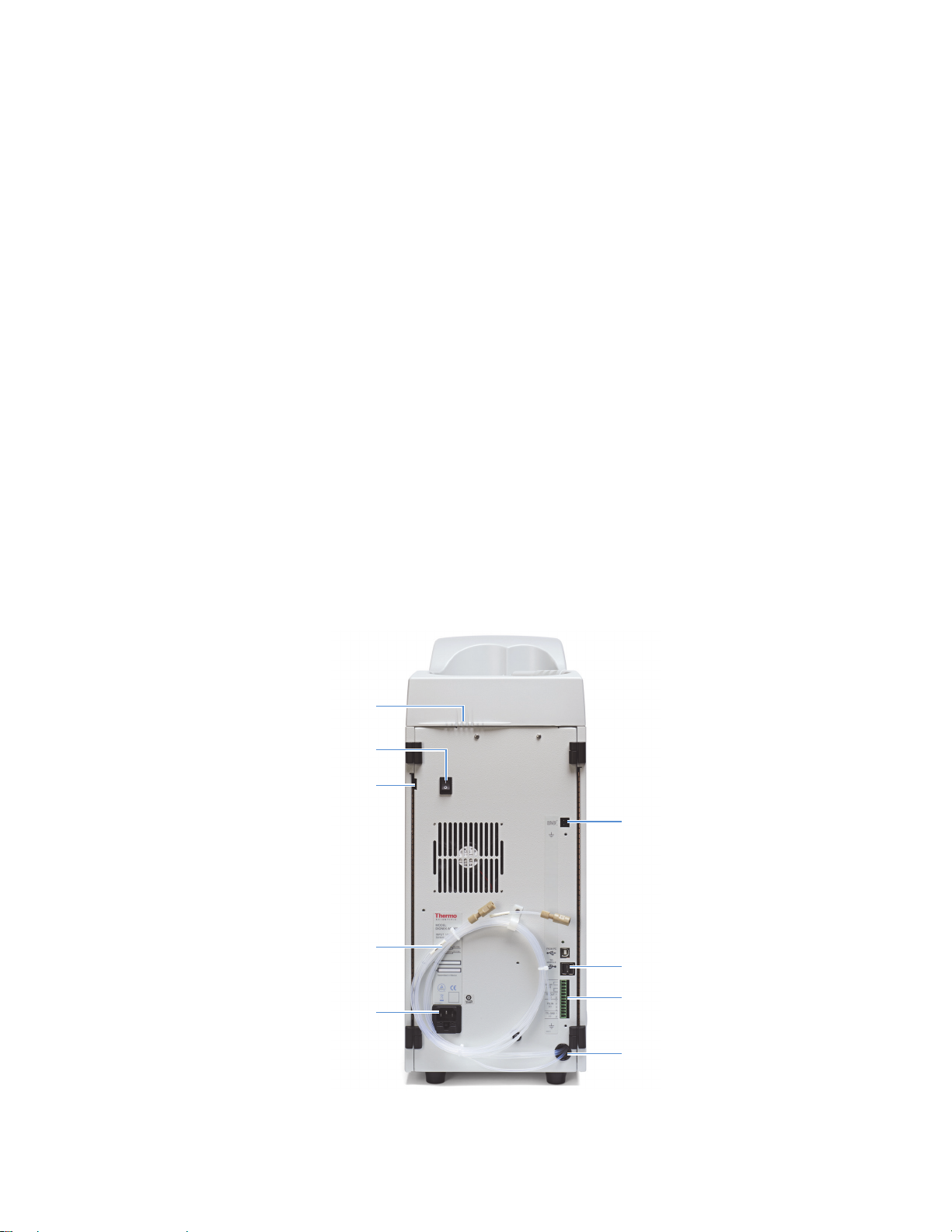
Column Heater (Optional)
Upper tubing chase
Analog output connector
Waste lines (3)
Main power receptacle
USB connectors
TTL and Relay connector strip
Lower tubing chase
Power switch
Tubing clips
The column heater controls the temperature of the separator and guard columns. The
temperature can be set to between 30 and 60 °C; however, it must be set to at least 5 °C above
the ambient temperature. For more information, see “Column Heater (Optional)” on
page 27.
Eluent Valve
The eluent valve controls the flow from the eluent reservoir. The eluent valve opens
automatically when the pump is started and closes when the pump is turned off. For more
information, see “Eluent Valve” on page 21.
Tubing Chases
The upper tubing chase routes tubing from the top cover to the component panel. The lower
tubing chase routes tubing from the component panel, through the interior of the system, to
the rear panel.
2
Description
Operating Features
Rear Panel
Figure 6 shows the Dionex Aquion RFIC rear panel.
Figure 6. Dionex Aquion RFIC rear panel
Thermo Scientific Dionex Aquion RFIC Operator’s Manual 11
Page 28
2
Description
Operating Features
Analog Output Connector
The analog output connector outputs conductivity data (as a 0 to 1 V signal) to an integrator
or recording device. For connection and setup information, refer to the Dionex Aquion RFIC
installation instructions.
USB Connectors
The USB receptacle provides a connection to the Chromeleon computer. Two USB ports are
available for connecting to other USB devices. For connection instructions, refer to the
Dionex Aquion RFIC installation instructions.
TTL and Relay Connector
The TTL and Relay connector strip provides two TTL outputs, two relay outputs, and four
TTL inputs. The outputs can be used to control functions in other TTL- or relay-controllable
devices. The inputs can be used to switch the injection valve position, turn on the pump,
perform an autozero command, and send an event mark to the analog output. For connection
instructions, see “TTL and Relay Control” on page 131.
Tubing Chase
The lower tubing chase routes tubing from the rear panel to the component panel.
Tubing Clips
The tubing clips hold tubing routed from the top cover in place.
Power Switch
The power switch provides on/off control of power to the Dionex Aquion RFIC.
Main Power Receptacle
The power supply cord plugs into the AC power receptacle.
CAUTION The power supply cord is used as the main disconnect device. Verify that the
socket-outlet is near the Dionex Aquion RFIC and is easily accessible.
MISE EN GARDE Le cordon d'alimentation principal est utilisé comme dispositif
principal de débranchement. Veillez à ce que la prise de base soit située/installée près du
module et facilement accessible.
12 Dionex Aquion RFIC Operator’s Manual Thermo Scientific
Page 29

VORSICHT Das Netzkabel ist das wichtigste Mittel zur Stromunterbrechung. Stellen Sie
sicher, daß sich die Steckdose nahe am Gerät befindet und leicht zugänglich ist.
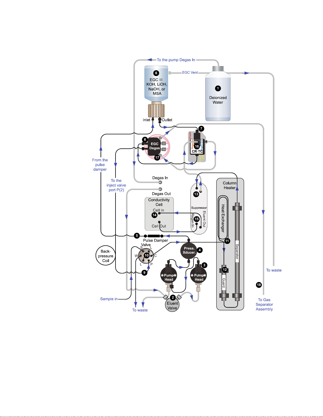
Flow Schematics
• Figure 7 illustrates the liquid flow path when the components required for producing
• Figure 8 illustrates the liquid flow path when the components required for producing
2
Description
Flow Schematics
KOH, LiOH, NaOH, or MSA eluent are installed. The required components include the
corresponding type of Dionex EGC III Eluent Generator Cartridge and a Dionex
CR-TC.
carbonate eluent are installed. The required components include a Dionex EGC 500
K
Eluent Generator Cartridge and aThermo Scientific™ Dionex™ EGC 500
2CO3
Carbonate Mixer.
Thermo Scientific Dionex Aquion RFIC Operator’s Manual 13
Page 30
2
Description
Flow Schematics
Figure 7. Dionex Aquion RFIC flow schematic: KOH, LiOH, NaOH, or MSA eluent generation
14 Dionex Aquion RFIC Operator’s Manual Thermo Scientific
Page 31

Flow Description for KOH, LiOH, NaOH, or MSA Eluent Generation
11121314151617
18
See Figure 7 for an illustration of the flow path described below.
2
Description
Flow Schematics
• Deionized water from the reservoir
then through the eluent valve
pressure transducer
through a pulse damper
, which measures the system pressure. From there, the water flows
, which smooths minor pressure variations from the pump to
flows first through the pump degas assembly, and
to the pump . The water is then pushed through the
minimize baseline noise.
• Water then flows into the eluent generator cartridge (Dionex EGC)
, which generates
the programmed concentration of eluent. Eluent exits the cartridge and flows through the
Dionex CR-TC
tubing assembly
• After sample is loaded into the sample loop
(which traps ionic contaminants), through the Dionex EGC degas
, and on to the injection valve .
and the injection valve is toggled to the
Inject position, eluent passes through the sample loop.
• The eluent/sample mixture is pumped through the heat exchanger , which heats the
mixture to the column heater temperature. The mixture then goes to the guard and
separator columns and through the suppressor .
• From the suppressor, the mixture flows through the conductivity cell , where the
analytes are detected. A digital signal is sent to Chromeleon software. Analog output can
be collected simultaneously.
• The mixture flows out of the conductivity cell and is recycled back into the suppressor ,
where it is the water source for the regenerant chamber.
• Regenerant waste from the suppressor is directed back to the Dionex CR-TC , and
then to the Dionex EGC degas tubing , where any released hydrogen or oxygen gas is
removed before it is sent to the gas separator assembly and then to waste .
Thermo Scientific Dionex Aquion RFIC Operator’s Manual 15
Page 32

2
Description
Flow Schematics
Figure 8. Dionex Aquion RFIC flow schematic: carbonate eluent generation
16 Dionex Aquion RFIC Operator’s Manual Thermo Scientific
Page 33

Flow Description for Carbonate Eluent Generation
11121314151617
See Figure 8 for an illustration of the flow path described below.
2
Description
Flow Schematics
• Deionized water from the reservoir
then through the eluent valve
pressure transducer
through a pulse damper
minimize baseline noise.
• Water then flows into the eluent generator cartridge (Dionex EGC)
the programmed concentration of carbonate eluent. Eluent exits the cartridge and flows
through the Dionex EGC degas tubing assembly
EGC 500 Carbonate Mixer
on to the injection valve
• After sample is loaded into the sample loop
Inject position, eluent passes through the sample loop.
• The eluent/sample mixture is pumped through the heat exchanger , which heats the
mixture to the column heater temperature. The mixture then goes to the guard and
separator columns and through the suppressor .
• From the suppressor, the mixture flows through the conductivity cell , where the
analytes are detected. A digital signal is sent to Chromeleon software. Analog output can
be collected simultaneously.
• The mixture flows out of the conductivity cell and is recycled back into the suppressor ,
where it is the water source for the regenerant chamber.
, which measures the system pressure. From there, the water flows
, which smooths minor pressure variations from the pump to
(to ensure a homogeneous eluent concentration), and then
.
flows first through the pump degas assembly and
to the pump. The water is then pushed through the
, which generates
. Eluent then goes to the Dionex
and the injection valve is toggled to the
• Regenerant waste from the suppressor is directed back to the Dionex EGC degas
tubing , where any released hydrogen or oxygen gas is removed before it is sent to the
gas separator assembly and then to waste .
Thermo Scientific Dionex Aquion RFIC Operator’s Manual 17
Page 34

2
Description
Chromeleon Chromatography Data System
Chromeleon Chromatography Data System
Chromeleon software is used to control the Dionex Aquion RFIC and to acquire and process
data. There are two modes of software control:
•With automated control, you create a list of control commands to be executed in
chronological order.
•With direct control, you use the controls on the Chromeleon ePanel Set (see Figure 9) to
issue commands and enter operating parameters. Direct control commands and
parameter settings are executed as soon as they are entered.
The Home ePanel of the Chromeleon ePanel Set includes system status information, a
signal plot, and controls for the most commonly used system functions. Click the tabs at
the top of the ePanel to access detailed status and control functions for each system
component (pump, detector, and so on).
For instructions on how to connect to the ePanel Set, see “Connecting to Chromeleon”
on page 35.
Figure 9. Example Chromeleon ePanel Set
If the function to be performed is not available on the ePanel Set, click the Command
icon on the Instrument toolbar above the ePanel Set (or press the F8 key) to open the
Chromeleon Command window (see Figure 10). From there, you can access all commands
available for the system.
18 Dionex Aquion RFIC Operator’s Manual Thermo Scientific
Page 35

Figure 10. Chromeleon Command window
2
Description
System Component Details
System Component Details
This section provides details about Dionex Aquion RFIC system components, including the
vacuum degas assembly (optional), pump, eluent generator, injection valve, column heater
(optional), suppressor, and conductivity cell.
Vacuum Degas Assembly (Optional)
The vacuum degas assembly provides online eluent degassing at a user-specified time and
duration. The assembly, which must be installed in the Dionex Aquion RFIC at the factory,
consists of:
• A single-channel degas chamber (with degas membranes) with internal capacity of 17 mL
• A dual-stage diaphragm vacuum pump
• A solenoid valve
• An on-board vacuum sensor
• The electronics required to operate the vacuum pump
• Tubing, fittings, and other accessories
Thermo Scientific Dionex Aquion RFIC Operator’s Manual 19
Page 36

2
Description
System Component Details
To select the degas operating mode
By default, the Dionex Aquion RFIC monitors the degas pressure reading and turns the degas
pump on and off as required. (This is the Monitor mode.) Follow the instructions here to
select a different operating mode.
1. Open the Chromeleon Instrument Configuration Manager.
2. Double-click the Aquion IC System icon under the instrument.
3. In the Properties dialog box, click the Options tab (see Figure 11).
Figure 11. Properties dialog box: Options tab page
4. Select the preferred options.
• Always Off: The degas pump is always off.
• Always On: The degas pump is always on.
IMPORTANT Never select the Always On option for routine operation. The Always
On option is intended for testing purposes only.
• Cycle: The degas pump cycles on and off. In the On field, specify for how long the
degas pump should run during a cycle. In the Off field, specify the time between
cycles.
• Monitor: (default mode) The Dionex Aquion RFIC monitors the degas pressure
reading and turns the degas pump on and off as required.
20 Dionex Aquion RFIC Operator’s Manual Thermo Scientific
Page 37

Eluent Valve
2
Description
System Component Details
The eluent valve (see Figure 12) controls the flow from the eluent reservoir. The valve opens
automatically when the pump is started and closes when the pump is turned off.
You can also open and close the valve manually, using controls on the Chromeleon ePanel (see
“Chromeleon Chromatography Data System” on page 18). This lets you perform service
procedures on pump components without eluent leaks occurring.
Figure 12. Eluent valve
Pump
Primary Pump Head
The Dionex Aquion RFIC pump is a microprocessor-based eluent delivery system. Its variable
speed, dual-piston series design ensures pulse-free pumping for the most demanding
applications.
The primary pump head pumps eluent into the secondary pump head (see Figure 13). The
check valves, which prevent reverse flow through the pump, are on the bottom (inlet) and top
(outlet) of the primary pump head. The priming valve is on the front of the pump head.
To open the priming valve, turn the knob one-quarter to one-half turn counterclockwise.
When the priming valve is open, liquid can flow into and out of the primary pump head via
the port on the front of the valve.
Note The priming valve must be open when the pump is being primed with a syringe (see
“Priming the Pump (Standard Procedure)” on page 90) or with isopropyl alcohol (see
“Priming the Pump with Isopropyl Alcohol” on page 92).
Thermo Scientific Dionex Aquion RFIC Operator’s Manual 21
Page 38

2
Secondary
pump head
Waste valve
Pressure
transducer
Outlet check valve
Primary pump head
Priming valve
Inlet check valve
Description
System Component Details
Secondary Pump Head
The secondary pump head delivers eluent to the remainder of the chromatography system
(the injection valve, column, and detector). The waste valve is on the front of the secondary
pump head (see Figure 13).
To open the waste valve, turn the knob one-quarter to one-half turn counterclockwise. When
the waste valve is in the open position, all pump flow is directed to waste.
Note The waste valve must be open when the pump is being primed using the Prime
button (see “Priming the Pump (Standard Procedure)” on page 90).
Figure 13. Secondary pump head
Pressure Transducer
Pulse Damper
Flow exiting the secondary pump head is directed to the pressure transducer (see Figure 13),
which measures the system pressure.
Pressure readings are displayed on the Chromeleon ePanel. Monitor readings periodically to
check that the pumping system is delivering smooth, accurate flow.
The system pressure should remain consistent, with no more than a 3% difference from one
pressure reading to the next. High and low pressure limits can be used to stop the pump flow
if a limit is exceeded. You can set the pressure limits from either the Chromeleon Instrument
Configuration Manager or the ePanel. For instructions on what to do if a pressure limit is
exceeded, see “Troubleshooting Error Messages” on page 51.
Flow output from the pressure transducer continues to the pulse damper, which smooths
minor pressure variations. From there, flow is directed to the injection valve and then to the
remainder of the chromatography system.
22 Dionex Aquion RFIC Operator’s Manual Thermo Scientific
Page 39

Piston Seal Wash
Eluent Generator
2
Description
System Component Details
The pump includes a piston seal wash assembly that can be set up to continuously rinse the
back of the piston seals to remove salt crystals and prolong the life of the seals. To use this
feature, an external wash solution must be connected to the system. The wash solution is
either ASTM filtered, Type I (18 megohm-cm) deionized water or a combination of deionized
water and 10% or 20% isopropyl alcohol. For connection instructions, refer to the Dionex
Aquion RFIC installation instructions.
For continued protection of the pump, replace the piston rinse seals and O-rings in the pump
housing every 6 months, or whenever you replace the main piston seals (see “Replacing a
Pump Piston Seal and Piston Rinse Seal” on page 78).
The eluent generator produces high-purity eluents online, using only deionized water as the
carrier. The eluent generator consists of an eluent generator cartridge (Dionex EGC) for
eluent generation, as well as a high-pressure degas tubing assembly for removal of the
electrolysis gases created during eluent generation.
Note The waste, gas separator tube (P/N 045460) should be connected to the system
waste line during installation. For more information, refer to the Dionex Aquion RFIC
installation instructions.
Several eluent generator cartridge types are available for use with the Dionex Aquion RFIC
(see Ta b le 3 ). Each cartridge contains 900 mL of the appropriate electrolyte concentrate
solution for eluent generation. For more information, refer to the Dionex EGC manual.
Table 3. Dionex EGC cartridges for the Dionex Aquion RFIC
Eluent generator cartridge P/N Description
Dionex EGC III KOH 074532 Generates potassium hydroxide eluent for
anion exchange separations
Dionex EGC III LiOH 074534 Generates lithium hydroxide eluent for
anion exchange separations
Dionex EGC III NaOH 074533 Generates sodium hydroxide eluent for
anion exchange separations
Dionex EGC III MSA 074535 Generates methanesulfonic acid eluent for
cation exchange separations
Dionex EGC 500 K
2CO3
088453 Generates potassium carbonate eluent for
anion exchange separations; requires
installation of a Dionex EGC 500
Carbonate Mixer
Thermo Scientific Dionex Aquion RFIC Operator’s Manual 23
Page 40

2
Description
System Component Details
Select the concentration of eluent to be generated on the Chromeleon ePanel. The allowable
eluent concentration depends on the flow rate, suppressor type, and cartridge type (see
Ta bl e 4 ).
Table 4. Eluent concentration ranges
Eluent generator cartridge Eluent concentration range
Dionex EGC III KOH 0.1 to 100 mM at 0.1 to 1.0 mL/min flow
0.1 to X mM at 1.0 to 3.0 mL/min flow
where X = 100/flow in mL/min
Dionex EGC III LiOH 0.1 to 80 mM at 0.1 to £ 1.0 mL/min flow
0.1 to X mM at 1.0 to £ 3.0 mL/min flow
where X = 80/flow in mL/min
Dionex EGC III NaOH 0.1 to 100 mM at 0.1 to 1.0 mL/min flow
0.1 to X mM at 1.0 to 3.0 mL/min flow
where X = 100/flow in mL/min
Dionex EGC III MSA 0.1 to 100 mM at 0.1 to 1.0 mL/min flow
0.1 to X mM at 1.0 to 3.0 mL/min flow
where X = 100/flow in mL/min
Dionex EGC 500 K
2CO3
Eluent Generator Cartridge (Dionex EGC) Holder
The Dionex EGC is installed in a cartridge holder mounted on the top cover of the Dionex
Aquion RFIC (see Figure 4). The cartridge holder also houses a high-pressure degas tubing
assembly. Tubing and fittings for plumbing the cartridge, degas assembly, and Dionex CR-TC
are included with the holder. For more information, refer to the Dionex Aquion RFIC
installation instructions.
Backpressure Coil (Optional)
The Dionex EGC requires at least 14 MPa (2000 psi) of system backpressure for removal of
electrolysis gas from the eluent produced by the cartridge. A system backpressure of 16 MPa
(2300 psi) is ideal.
If the system backpressure is too low, Thermo Fisher Scientific recommends connecting a
backpressure coil (P/N 053765) between the injection valve and the Dionex EGC
OUT port. For more information, refer to the Dionex Aquion RFIC installation instructions.
0.1 to 15 mM at 0.1 to 1.0 mL/min flow
0.1 to X mM at 1.0 to 2.0 mL/min flow
where X = 15/flow in mL/min
ELUENT
24 Dionex Aquion RFIC Operator’s Manual Thermo Scientific
Page 41

Continuously Regenerated Trap Column (Dionex CR-TC)
To W aste
Sample In
To Co l umn
From Pump
Sample
Loop
LOAD POSITION
To W aste
Sample In
From Pump
Sample
Loop
INJECT POSITION
To Column
The Dionex CR-TC is a high-pressure electrolytically-regenerated trap column. The column
is designed to remove anionic or cationic contaminants in the eluent or deionized water and
to reduce drift during gradient separations. The following columns can be used with the
Dionex Aquion RFIC:
• CR-ATC Continuously Regenerated Anion Trap Column (P/N 060477)
• CR-CTC II Continuously Regenerated Cation Trap Column (P/N 060262)
For more information, refer to the column manual.
Carbonate Mixer
To ensure a homogeneous eluent concentration, the carbonate eluent generated by the Dionex
EGC 500 K
to the injection valve. The mixer is included in the following kits:
• Dionex EGC 500 Carbonate Mixer Kit, 2 mm (P/N 088467)
flows through a Dionex EGC 500 Carbonate Mixer before being delivered
2CO3
2
Description
System Component Details
Injection Valve
• Dionex EGC 500 Carbonate Mixer Kit, 4 mm (P/N 088468)
The injection valve (P/N 057968) is a 6-port, electrically-activated valve. A 25-μL sample
loop (P/N 042857) is installed on the valve at the factory.
The valve has two operating positions: Load and Inject (see Figure 14).
Figure 14. Injection valve flow schematics
Thermo Scientific Dionex Aquion RFIC Operator’s Manual 25
Page 42

2
Description
System Component Details
Eluent flows through the Load or Inject path, depending on the valve position.
• Load position: Sample is loaded into the sample loop, where it is held until injection.
Eluent flows from the pump, through the valve, and to the column, bypassing the sample
loop. Sample flows from the syringe or automated sampler line (if installed), through the
valve, and into the sample loop. Excess sample flows out to waste.
• Inject position: Sample is swept to the column for analysis. Eluent flows from the pump,
through the sample loop, and on to the column, carrying the contents of the sample loop
with it. For more information, see “Loading and Injecting Samples” on page 41.
Figure 15 shows the injection valve connections. The injection valve is plumbed at the factory
with all tubing and fittings for connection to the pump, injection port, column, and waste. A
25-μL PEEK™ (polyether ether ketone) sample loop (P/N 042857) is installed between ports
L (1) and L (4). If necessary, replace the pre-installed 25-μL loop with a loop that has a
different sample injection volume. Thermo Fisher Scientific offers sample loops in various
sizes.
Figure 15. Injection valve plumbing
Auxiliary Valve (Optional)
The auxiliary valve is a 2-position, electrically-activated, high-pressure Rheodyne valve. The
PEEK valve is available in two models: a 6-port valve and a 10-port valve. The auxiliary valve
must be installed on-site by Thermo Fisher Scientific field service personnel.
When installed, the valve enables a variety of sample preparation activities, including:
• Online filtration
• Matrix elimination (for example, the removal of high backgrounds of chloride or organic
material)
• Concentrator-based techniques
• Conditional injections (large loop/small loop applications where the data system
monitors sample concentration and reinjects the sample, using the smaller loop, if the
concentration is too high)
26 Dionex Aquion RFIC Operator’s Manual Thermo Scientific
Page 43

• AutoNeutralization™
• Matrix diversion prior to MS (mass spectrometry) detection
Column Heater (Optional)
The column heater (see Figure 16) provides temperature control for the separator and guard
columns.
Figure 16. Column heater
2
Description
System Component Details
The heater temperature can be set to between 30 °C and 60 °C. The set temperature must be
at least 5 °C above the ambient temperature. Setting the temperature to 0 °C turns off the
column heater.
A thermistor mounted in the heater block monitors the temperature. If the temperature
exceeds 65 °C, the column heater is shut off and an error message is displayed in the
Chromeleon audit trail. For troubleshooting guidance, see “Column heater exceeds safe
temperature” on page 51.
The column heater can be installed at the factory or installed on-site by Thermo Fisher
Scientific field service personnel.
Thermo Scientific Dionex Aquion RFIC Operator’s Manual 27
Page 44

2
Description
System Component Details
Suppressor
The suppressor reduces the eluent conductivity and enhances the conductivity of the sample
ions, thereby increasing detection sensitivity. Ta b le 5 lists the suppressors that can be used
with the Dionex Aquion RFIC. For details about these suppressors (or guidelines for selecting
a suppressor for an application), refer to the suppressor manuals.
Table 5. Thermo Scientific suppressors for the Dionex Aquion RFIC
Part number Suppressor
088667 Dionex ADRS 600 Anion Dynamically Regenerated
Suppressor (2 mm)*
088666 Dionex ADRS 600 Anion Dynamically Regenerated
Suppressor (4 mm)*
088670 Dionex CDRS 600 Cation Dynamically Regenerated
Suppressor (2 mm)*
088668 Dionex CDRS 600 Cation Dynamically Regenerated
Suppressor (4 mm)*
085028 Dionex AERS 500 Carbonate Electrolytically Regenerated
085029 Dionex AERS 500 Carbonate Electrolytically Regenerated
*The Dionex DRS is capable of operation in two power modes: Dynamic mode, which uses
constant voltage, and Legacy mode, which uses constant current. However, when installed
in the Dionex Aquion RFIC, the Dionex DRS operates in Legacy mode only.
DS6 Heated Conductivity Cell
The flow-through conductivity cell measures the electrical conductance of analyte ions as they
pass through the cell. Two passivated 316 stainless steel electrodes are permanently sealed into
the PEEK cell body. The cell design provides efficient sweep-out, low volume (1
dispersion. Temperature control and compensation help verify good peak reproducibility and
baseline stability.
Temperature Control
Temperature directly affects the conductivity of a solution. For example, laboratory heating
and air conditioning systems can cause a regular slow cycling in the baseline. This, in turn,
can affect the reproducibility of an analysis. The higher the conductivity, the more
pronounced the effect.
Suppressor (2 mm)
Suppressor (4 mm)
μL), and low
28 Dionex Aquion RFIC Operator’s Manual Thermo Scientific
Page 45

In ion analysis, the effect of temperature variation is minimized by suppressing eluent
conductivity. To further reduce the effect of temperature variation, a heater inside the cell
regulates the temperature. The cell heater temperature can be set to between 30 °C and 55 °C.
The set temperature must be at least 7 °C above the ambient temperature. Setting the cell
temperature to 0 °C turns off the cell heater.
Temperature Compensation
Built-in preset temperature compensation of 1.7% per °C helps minimize changes in the
baseline or in peak heights when the operating temperature is different from the temperature
at which the cell was calibrated.
DS6 Heated Conductivity Cell Components
The CELL IN and CELL OUT fittings on the front cover of the cell are used to connect the cell
to the suppressor (see Figure 5). The remaining cell components are mounted behind the
component panel.
2
Description
System Component Details
The cell must be installed at the factory or ordered separately and installed on-site by Thermo
Fisher Scientific field service personnel.
Thermo Scientific Dionex Aquion RFIC Operator’s Manual 29
Page 46

2
Description
System Component Details
30 Dionex Aquion RFIC Operator’s Manual Thermo Scientific
Page 47

3
Operation
This chapter describes routine operating and maintenance procedures for the Dionex Aquion
RFIC.
Note The instructions in this chapter assume that the initial setup of the Dionex Aquion
RFIC (including configuring the system in a Chromeleon instrument) has been
completed. If this is not the case, set up the system before proceeding. For more
information, refer to the Dionex Aquion RFIC installation instructions.
Contents
• Operation Overview
• Turning On the System Power
• Connecting to Chromeleon
• Setting Up the Eluent Reservoir
• Checking All Connections
• Priming the Pump
• Setting System Operating Conditions
• Equilibrating the System and Verifying Operational Status
• Preparing Samples
• Loading and Injecting Samples
• Processing Samples
Thermo Scientific Dionex Aquion RFIC Operator’s Manual 31
Page 48

3
Power up the system
Set up the reservoir
(or RFIC-ER system)
Start Chromeleon
Check all
connections
Prime the pump
Set operating
conditions
Equilibrate the
system
Verify operating
status
Process samples
Prepare samples
Operation
Operation Overview
Operation Overview
Figure 17 shows the basic steps for routine operation of the Dionex Aquion RFIC.
Figure 17. System operation overview
32 Dionex Aquion RFIC Operator’s Manual Thermo Scientific
Page 49

Sample Processing Overview
Samples can be run manually (one at a time) or else grouped and run automatically in
batches. Figure 18 shows the typical steps for each type of sample processing.
Figure 18. Sample processing overview
3
Operation
Operation Overview
Thermo Scientific Dionex Aquion RFIC Operator’s Manual 33
Page 50

3
Power switch
Operation
Turning On the System Power
Turning On the System Power
To turn on the power
1. Press the main power switch on the Dionex Aquion RFIC rear panel (see Figure 19).
2. Turn on the power to the computer and the autosampler (if installed).
Figure 19. Dionex Aquion RFIC rear panel
Table 6. Dionex Aquion RFIC power-up conditions
Feature Power-up condition
Pump Off
Injection valve Load position
Cell Reading current value
Suppressor Off*
Cell heater Set to the last value used. When the system is turned on for the
Column oven temperature
(optional)
first time, the default is 35 °C.
Set to the last value used. When the system is turned on for the
first time, the default s 30 °C.
Eluent generator Off*
Dionex CR-TC Off
* When you start the suppressor or eluent generator, the value used last is restored.
34 Dionex Aquion RFIC Operator’s Manual Thermo Scientific
Page 51

Connecting to Chromeleon
To start the Chromeleon Instrument Controller Service
On the Windows taskbar, right-click the Chromeleon icon in the system tray and
click Start Chromeleon Instrument Controller. The icon changes to to indicate that
the Instrument Controller Service is starting. When the Instrument Controller Service is
running (idle), the icon changes to gray .
–or–
If the Chromeleon icon is not on the taskbar, click Start > All Programs > Thermo
Chromeleon 7 > Services Manager to open the Services Manager and click Start
Instrument Controller.
To start the Chromeleon client
Click Start > All Programs > Thermo Chromeleon 7 > Chromeleon 7.
3
Operation
Connecting to Chromeleon
To display the ePanel Set
1. In the Console, click the Instruments Category Bar.
2. Select the name of the instrument in which the Dionex Aquion RFIC is configured.
Chromeleon will connect to the instrument and display the ePanel Set (see Figure 20).
Figure 20. Example Chromeleon ePanel Set
Thermo Scientific Dionex Aquion RFIC Operator’s Manual 35
Page 52

3
Operation
Setting Up the Eluent Reservoir
Setting Up the Eluent Reservoir
The Dionex Aquion RFIC does not require pressurized reservoirs. However, if eluent is
manually degassed or is sensitive to contamination, Thermo Fisher Scientific recommends
pressurizing the reservoir with helium or nitrogen.
The air regulator accessory (P/N 060054) required for pressurizing the eluent reservoir must
be ordered separately. For more information, refer to the Dionex Aquion RFIC installation
instructions.
To filter the deionized water
Filtering removes small particulates in the deionized water that may contaminate the pump
check valves and cause erratic flow rates or loss of prime.
1. Locate the end-line filter (P/N 045987) provided in the Dionex Aquion RFIC Ship Kit
(P/N 064375).
2. Install the end-line filter on the end of the deionized water line, inside the reservoir.
3. Verify that the end of the filter extends to the bottom of the reservoir and that the filter is
submerged in deionized water. This prevents air from being drawn through the lines.
To fill the eluent reservoir
Fill the reservoir with ASTM filtered, Type I (18 megohm-cm) deionized water that meets the
specifications in “Deionized Water Requirements for IC” on page vi.
IMPORTANT After filling the reservoir, immediately set the eluent fill level in
Chromeleon (see below).
To set the eluent level
1. On the Chromeleon ePanel Set, click the Pump_ECD tab.
2. Under Pump_ECD, drag the Eluent Fill Level slider to the location that corresponds to
the current eluent level (see Figure 21).
During operation, Chromeleon determines the eluent usage by monitoring the flow rate and
the length of time the pump is on. The eluent fill level volume is updated as the eluent is
depleted. If the level falls below 200 mL, a warning message is displayed. The warning is
repeated if the level falls to 100 mL and to 0 mL.
IMPORTANT To ensure that the Eluent Fill Level display is accurate, always enter the
level immediately after filling the eluent reservoir. The Dionex Aquion RFIC does not
automatically detect when the reservoir is filled, nor when it is empty.
36 Dionex Aquion RFIC Operator’s Manual Thermo Scientific
Page 53

Figure 21. Eluent Fill Level display in Chromeleon
To connect the eluent reservoir
3
Operation
Checking All Connections
If it is not already connected, connect the
the
ELUENT IN line, which extends from the tubing chase on the top cover of the Dionex
Aquion RFIC.
Checking All Connections
1. Make sure the eluent reservoir is filled.
2. Make sure the
ELUENT IN line, which extends from the tubing chase on the top cover of the Dionex
Aquion RFIC.
3. Make sure the Dionex EGC electrical cable (blue) is connected to the
4. Make sure the Dionex CR-TC electrical cable (black) is connected to the
connector.
Priming the Pump
IMPORTANT If you changed the eluent—or if the eluent lines are dry—prime the eluent
lines with a syringe (see page 90) before starting this pump priming procedure.
ELUENT BOTTLE OUT line from the reservoir cap to
ELUENT BOTTLE OUT line from the reservoir cap is connected to the
EGC connector.
CR-TC
To prime the pump
1. Verify that the priming valve on the primary pump head is closed (turned all the way
clockwise) (see Figure 22).
Thermo Scientific Dionex Aquion RFIC Operator’s Manual 37
Page 54

3
Priming Valve
Waste Valve
Primary
Pump Head
Secondary
Pump Head
(open)
(close)
Operation
Setting System Operating Conditions
Figure 22. Priming the pump
2. Open the waste valve on the secondary pump head by turning the knob one-quarter to
one-half turn counterclockwise. (Opening the waste valve directs the eluent flow path to
waste and eliminates backpressure.)
3. On the Chromeleon ePanel Set, click the Pump_ECD tab.
4. Under Pump_ECD, click the Prime button. The pump will begin pumping at
approximately 3 mL/min.
5. Continue priming the pump until all air and previous eluent are purged and no air
bubbles are exiting the waste line.
6. Under Pump_ECD, click the Off
7. Close the waste valve. Do not overtighten. The pump is now ready for operation.
Setting System Operating Conditions
This section provides an overview of the steps required to start the system and select the initial
system operating parameters. Actual operating parameters (including flow rate, cell heater
temperature, and suppressor current) depend on the application you plan to run. For the
required settings for your application, refer to the column manual.
Set or verify system operating parameters from the Chromeleon ePanel. Parameters can also
be set automatically, by loading a Chromeleon sequence.
Note Clicking the On or Off button on the Chromeleon ePanel starts or stops the pump,
suppressor, Dionex EGC, and Dionex CR-TC. Clicking On restores the flow rate,
suppressor current, and eluent concentration settings that were in effect when the system
was shut down.
button to turn off the pump.
To set operating conditions
1. Verify that the pump is on and that the flow rate setting is correct.
2. Verify that the suppressor current is on and that the setting is correct.
3. Verify that the Dionex EGC is on and that the eluent concentration setting is correct.
38 Dionex Aquion RFIC Operator’s Manual Thermo Scientific
Page 55

Equilibrating the System and Verifying Operational Status
4. Verify that the Dionex CR-TC is on.
5. Verify that the cell heater temperature is set to the correct value.
6. Verify that the column heater temperature is set to the correct value.
Equilibrating the System and Verifying Operational Status
This section provides an overview of the steps needed to equilibrate the system and verify
operational readiness.
Note Equilibration time varies, and it may take some time to reach the expected values.
To equilibrate the system and verify operational readiness
After setting operating conditions, allow the system to equilibrate. During equilibration, the
Chromeleon ePanel displays the background conductivity (the conductivity of the eluent
before sample injection) and the system backpressure.
3
Operation
1. Monitor the background conductivity to be sure that it is appropriate for your
application.
2. Click Autozero
on the ePanel to offset the detector background and zero the reading.
3. Monitor the system pressure to be sure that it is at the expected pressure for the installed
column and is stable.
• If the pressure is lower than expected, gas may be trapped in the system. To
release the gas, remove the pump fitting on port
(P) 2 on the injection valve.
Allow the air to escape, and then reconnect the fitting.
• If the pressure fluctuates by more than about 0.13 MPa (20 psi), prime the pump
(see “Priming the Pump (Standard Procedure)” on page 90). If this does not
resolve the issue, see “Pump Difficult to Prime or Loses Prime” on page 62 for
additional troubleshooting guidance.
• If the pressure is higher than expected, there may be a restriction in the system
plumbing. For troubleshooting guidance, see “Pump Difficult to Prime or Loses
Prime” on page 62.
4. Verify that the baseline conductivity is at the expected reading for your application and is
stable. In general, the reading should be <30
<2
μS for a system set up for cation analyses.
μS for a system set up for anion analyses and
• If the conductivity is too high, see “High Cell Output” on page 66 for
troubleshooting guidance.
• If there is baseline drift or excessive baseline “noise” (large fluctuations in
readings), see “Baseline Noise or Drift” on page 67 for troubleshooting guidance.
Thermo Scientific Dionex Aquion RFIC Operator’s Manual 39
Page 56

3
Operation
Preparing Samples
5. Verify that the cell heater temperature is at the set point and is stable. The temperature is
at equilibrium when the Set Temperature and Current Temperature readings are the
same.
6. If a column heater is installed, verify that the temperature is at the set point and is stable.
The temperature is at equilibrium when the Set Temperature and Current Temperature
readings are the same.
The system is now ready for sample processing.
Preparing Samples
This section provides basic information about collecting, storing, and preparing samples for
analysis.
Note You can begin preparing samples while the system is equilibrating.
Collecting and Storing Samples
Collect samples in high density polyethylene containers that have been thoroughly cleaned
with deionized water. Do not clean containers with strong acids or detergents because these
can leave traces of ions on the container walls. The ions may interfere with the analysis.
If samples will not be analyzed on the day they are collected, filter them through clean
0.45 μm filters immediately after collection; otherwise, bacteria in the samples may cause the
ionic concentrations to change over time. Refrigerating the samples at 4
reduce, but not eliminate, bacterial growth.
Analyze samples containing nitrite or sulfite as soon as possible. Nitrite oxidizes to nitrate, and
sulfite to sulfate, thus increasing the measured concentrations of these ions in the sample. In
general, samples that do not contain nitrite or sulfite can be refrigerated for at least one week
with no significant changes in anion concentrations.
Pretreating Samples
Analyze rainwater, drinking water, and air particulate leach solutions directly with no sample
preparation (other than filtering and possibly diluting).
Filter groundwater and wastewater samples through 0.45 μm filters before injection, unless
samples were filtered after collection.
° C (39° F) will
Before injection, pretreat samples that may contain high concentrations of interfering
substances by putting them through Thermo Scientific™ Dionex™ OnGuard™ cartridges. For
instructions, refer to the OnGuard cartridge manual.
40 Dionex Aquion RFIC Operator’s Manual Thermo Scientific
Page 57

Diluting Samples
3
Operation
Loading and Injecting Samples
Because the concentrations of ionic species in different samples can vary widely from sample
to sample, no single dilution factor can be recommended for all samples of one type. In some
cases (for example, many water samples), concentrations are so low that dilution is not
necessary.
To dilute the sample, use either eluent or ASTM filtered, Type I (18 megohm-cm) deionized
water that meets the specifications in “Deionized Water Requirements for IC” on page vi.
When using carbonate eluents, diluting with eluent minimizes the effect of the water dip at
the beginning of the chromatogram. If you dilute the sample with eluent, also use eluent from
the same lot to prepare the calibration standards. This is most important for fluoride and
chloride, which elute near the water dip.
To improve the accuracy of early eluting peak determinations, such as fluoride, at
concentrations below 50 ppb, dilute standards in eluent or spike the samples with
concentrated eluent to minimize the water dip. For example, spike a 100 mL sample with
1.0 mL of a 100 X eluent concentrate.
Loading and Injecting Samples
There are two techniques for loading samples into the sample loop:
• With an autosampler
• With a syringe or vacuum syringe via the injection port on the Dionex Aquion RFIC
front door (see Figure 2)
For autosampler injections, the injection port tubing must be disconnected from the Dionex
Aquion RFIC injection valve and replaced by the autosampler outlet tubing. Other setup
requirements vary, depending on the autosampler model.
Samples can be injected using either the standard injection valve or the optional auxiliary
valve (see “Auxiliary Valve (Optional)” on page 26). The injection valve (or auxiliary valve)
must be specified as the injection valve and linked to the autosampler in the Chromeleon
instrument. For more information, refer to the Chromeleon Help or user’s manual.
Setup for a Dionex AS-DV Autosampler
To use a Thermo Scientific™ Dionex™ AS-DV Autosampler, the Dionex Aquion RFIC
injection valve (or auxiliary valve) must be specified as the injection valve and linked to the
Dionex AS-DV in the Chromeleon instrument. For more information, refer to the
Chromeleon Help or user’s manual.
Thermo Scientific Dionex Aquion RFIC Operator’s Manual 41
Page 58

3
Operation
Loading and Injecting Samples
Setup for a Dionex AS-AP Autosampler
For setup information for a Thermo Scientific™ Dionex™ AS-SP Autosampler, refer to the
autosampler manual.
To load samples with a syringe
1. Verify that the injection port on the Dionex Aquion RFIC front door (see Figure 2) is
connected to sample port
Figure 23. Injection valve connections
S (5) on the injection valve (see Figure 23).
2. Fill the 1-cc syringe (P/N 016388) provided in the Dionex Aquion RFIC Ship Kit
(P/N 064375) with a calibration standard or sample.
3. Insert the syringe into the injection port on the Dionex Aquion RFIC front door (see
Figure 2).
4. Verify that the injection valve is in the Load position.
5. Overfill the sample loop with several sample loop volumes. Excess sample will exit
through the injection valve waste line.
6. Leave the syringe in the port and switch the injection valve to the Inject position (see “To
inject samples” on page 43).
To load samples with a vacuum syringe
1. Disconnect the waste line from port
W (6) on the injection valve (see Figure 23) and
replace it with a piece of PEEK or PTFE (polytetrafluoroethylene) tubing that is 25 to
30 cm (10 to 12 in) long.
2. Place the free end of the PEEK or PTFE line into the sample.
3. Verify that the injection valve is in the Load position.
4. Insert the 1-cc syringe (P/N 016388) provided in the Dionex Aquion RFIC Ship Kit
(P/N 064375) into the injection port on the Dionex Aquion RFIC front door (see
Figure 2) and pull out the plunger to draw the sample into the injection valve.
5. Switch the injection valve to the Inject position (see “To inject samples” on page 43).
42 Dionex Aquion RFIC Operator’s Manual Thermo Scientific
Page 59

To load samples with an autosampler
3
Operation
Processing Samples
1. Verify that the autosampler output line is connected to sample port
S (5) on the Dionex
Aquion RFIC injection valve.
2. Prepare and fill the sample vials and place them in the autosampler tray or cassette. For
detailed instructions, refer to the autosampler manual.
3. The sample loading process depends on the autosampler model. In general, one of the
following steps is required (for details, refer to the autosampler manual):
• Include the commands for controlling sample loading in a Chromeleon method. For
details, refer to the Chromeleon Help or user manual.
• Enter the commands for loading the sample on the autosampler front panel.
4. Switch the injection valve to the Inject position (see “To inject samples” on page 43).
To inject samples
After loading the sample in the sample loop, use one of the following methods to switch the
injection valve to the Inject position.
• Manually: Click the Inject button on the Chromeleon ePanel (see “Example Chromeleon
ePanel Set” on page 35).
• Automatically: Include an Inject command in a Chromeleon method. For details, refer to
the Chromeleon Help or user manual.
Processing Samples
There are two options for processing samples:
• Run samples manually, one at a time (see “Manual Sample Processing” on page 43).
• Group samples and run them automatically, in batches (see “Automated (Batch) Sample
Processing” on page 44).
Manual Sample Processing
To process samples manually, select operating parameters and commands from the
Chromeleon ePanel. Commands are executed as soon as they are entered.
1. Complete the instructions in “Turning On the System Power” on page 34 through
“Equilibrating the System and Verifying Operational Status” on page 39 to prepare the
Dionex Aquion RFIC for operation and to prepare the sample for processing.
2. Load the sample, using a syringe, vacuum syringe, or autosampler (see“Loading and
Injecting Samples” on page 41).
3. On the Chromeleon ePanel, click the Autozero
button.
Thermo Scientific Dionex Aquion RFIC Operator’s Manual 43
Page 60

3
Operation
Processing Samples
4. Inject the sample (see “To inject samples” on page 43). The signal plot is displayed on the
ePanel.
5. Monitor the chromatogram. When sample data has been collected, click the Monitor
Baseline button on the Instrument toolbar above the ePanel Set.
To save data from a manual run
Data from manual processing is saved in the manual sequence under the instrument folder in
the local data vault.
1. Select the manual folder and click File > Save As.
2. Enter a new name for the sequence.
3. Select the Save raw data
4. Click Save.
Automated (Batch) Sample Processing
Note This section provides a brief overview of the steps required to perform sample
analyses using Chromeleon. For detailed instructions, refer to the Chromeleon Help.
To process samples automatically, first add sample injections to a Chromeleon sequence. (A
sequence determines how a group of injections will be analyzed and the order in which they
will be run.) For each injection, a sequence typically includes the following elements:
•An instrument method—A predefined list of commands and parameters for controlling
the system and acquiring sample data.
• The chromatographic data acquired.
•A processing method—A predefined set of instructions for evaluating the acquired data.
• Templates for displaying chromatographic data on the screen and for printing reports.
There are two ways to create a sequence in Chromeleon:
check box.
• eWorkflows provide predefined templates and rules for creating new sequences. If they
have been defined for your laboratory, eWorkflows are the preferred method for creating a
new sequence.
• The Sequence Wizard provides a series of dialog boxes that guide you through the process
of creating a sequence.
After creating the sequence, you are ready to start batch processing.
1. Complete the instructions in “Turning On the System Power” on page 34 through
“Equilibrating the System and Verifying Operational Status” on page 39 to prepare the
Dionex Aquion RFIC for operation and to prepare the sample for processing.
44 Dionex Aquion RFIC Operator’s Manual Thermo Scientific
Page 61

3
Operation
Processing Samples
2. If an autosampler is installed: Prepare and fill the sample vials, and then place them in the
autosampler tray or cassette. For detailed instructions, refer to the autosampler manual.
If an autosampler is not installed: Load the sample into the injection valve sample loop
through the sample port on the Dionex Aquion RFIC front door (see “To load samples
with a syringe” on page 42).
3. Load the sequence into a queue and start the run. Chromeleon performs a Ready Check
to verify that the instrument is ready for operation and that the instrument methods
specified in the sequence are error-free. If the Ready Check passes (and if another
sequence is not currently running), the sequence is started.
Thermo Scientific Dionex Aquion RFIC Operator’s Manual 45
Page 62

3
Operation
Processing Samples
46 Dionex Aquion RFIC Operator’s Manual Thermo Scientific
Page 63

4
Maintenance
This chapter describes routine maintenance procedures for the Dionex Aquion RFIC that
users can perform. All other maintenance procedures must be performed by Thermo Fisher
Scientific personnel.
Daily Maintenance
• Check the Dionex Aquion RFIC component panel (see Figure 5) for leaks or spills. Wipe
up spills. Isolate and repair leaks (see “Liquid Leaks” on page 60). Rinse off any dried
eluent with deionized water.
• Check the eluent reservoir. When necessary, refill the reservoir with ASTM filtered, Type
I (18 megohm-cm) deionized water that meets the specifications listed in “Deionized
Water Requirements for IC” on page vi.
• Check the waste container and empty when needed.
Weekly Maintenance
• Check for crimps or discoloration in the fluid lines. Replace any pinched lines. Replace
damaged lines.
• Check for evidence of liquid leaks in the junctions between the pump heads and the
pump casting. If the piston seal wash tubing is not connected, check for evidence of
moisture in the drain tubes at the rear of the pump heads. Normal friction and wear may
gradually result in small liquid leaks around the piston seal. If unchecked, these leaks can
gradually contaminate the piston housing, causing the pump to operate poorly. If leaks
occur, replace the piston seals (see “Replacing a Pump Piston Seal and Piston Rinse Seal”
on page 78).
Thermo Scientific Dionex Aquion RFIC Operator’s Manual 47
Page 64

4
Maintenance
Semiannual Maintenance
• Check the end-line filter (P/N 045987) on the deionized water line for discoloration or
bacterial buildup, and change if needed. When new, end-line filters are pure white. If the
system is in continuous operation, change the end-line filter weekly (or whenever it
becomes discolored). Replace the filter more often if bacterial buildup is visible or if the
eluent does not contain solvent.
IMPORTANT It is especially important to replace end-line filters regularly when using
aqueous eluents, which may contaminate the filter with bacteria or algae. The bacterial
buildup may not be visible.
Semiannual Maintenance
• Replace the pump piston rinse seals and piston seals (see “Replacing a Pump Piston Seal
and Piston Rinse Seal” on page 78).
Annual Maintenance
• Thermo Fisher Scientific recommends performing preventive maintenance of the Dionex
Aquion RFIC annually, as well as before any scheduled Performance Qualification tests.
The Dionex Aquion RFIC Preventive Maintenance Kit (P/N 057954) includes
replacement parts and instructions.
• Rebuild the auxiliary valve, if installed (see “Rebuilding the Injection Valve or Auxiliary
Valv e” on page 74).
• If a Dionex AS-AP Autosampler is installed, perform the recommended annual preventive
maintenance procedure. The Dionex AS-AP Preventive Maintenance Kit (P/N 075000)
includes replacement parts and instructions.
• If a Dionex AS-DV Autosampler is installed, perform the recommended annual
preventive maintenance procedure. The Dionex AS-DV Preventive Maintenance Kit
(P/N 60-065335) includes replacement parts and instructions.
48 Dionex Aquion RFIC Operator’s Manual Thermo Scientific
Page 65

5
Troubleshooting
This chapter is a guide to troubleshooting issues that may arise during operation of the
Dionex Aquion RFIC.
If you are unable to resolve a problem by following the instructions here, contact Technical
Support for Dionex products. In the U.S. and Canada, call 1-800-532-4752. Outside the
U.S. and Canada, call the nearest Thermo Fisher Scientific office.
Contents
• Error Messages
• Troubleshooting Error Messages
• Troubleshooting System Component Symptoms
Note An interactive troubleshooting guide is available in Chromeleon. To access the
guide, click Troubleshooting and Diagnostics on the Instrument toolbar above the
ePanel Set and select Pump_ECD Device Troubleshooting.
Error Messages
The instrument control firmware installed in the Dionex Aquion RFIC periodically checks
the status of certain parameters. If a problem is detected, it is reported to Chromeleon and
logged in the software audit trail. Each error message is preceded by an icon that identifies the
seriousness of the underlying problem (see Ta b le 7 ).
Thermo Scientific Dionex Aquion RFIC Operator’s Manual 49
Page 66

5
Troubleshooting
Error Messages
Table 7. Chromeleon audit trail severity levels
Severity level Icon Description
Warning A message is displayed in the audit trail. If the system is
not running, it can be started; if a run is in progress,
the run is not interrupted. Nevertheless, you should
always attempt to remedy the situation.
Error A message is displayed in the audit trail or the Ready
Check results, and the system attempts to correct the
problem (sometimes by using an alternative
parameter). If a run is in progress, the run is not
interrupted. If the Ready Check is in progress, the
queue is not started until the error is resolved.
Abort A message is displayed in the audit trail and the
running queue is aborted.
Ta bl e 8 lists the most frequently observed Dionex Aquion RFIC error message and their
default severity levels. For troubleshooting guidance, refer to the page indicated in the table.
Table 8. Chromeleon audit trail error messages
Error message
Default severity
level
Column heater exceeds safe temperature Abort
Column heater open circuit Abort
Column heater short circuit Abort
CR-TC over current Warning
CR-TC stopped for zero flow Abort
EGC board not present Warning
EGC calibration error Abort
EGC disconnected error Abort
EGC invalid concentration vs. flow rate Warning
EGC invalid flow rate Warning
EGC over current Abort
EGC over voltage Abort
Hardware not present Error
See
page 51
page 51
page 52
page 52
page 52
page 52
page 53
page 53
page 53
page 54
page 54
page 54
page 55
Leak sensor wet Warning
Load/Inject valve error Abort
Option not installed Error
50 Dionex Aquion RFIC Operator’s Manual Thermo Scientific
page 55
page 55
page 56
Page 67

Table 8. Chromeleon audit trail error messages, continued
5
Troubleshooting
Troubleshooting Error Messages
Error message
Pump motor lost control Warning
Pump over pressure Abort
Pump pressure hardware error Abort
Pump stopped due to lost USB communication error Abort
Pump under pressure Abort
Second valve error Abort
Suppressor not connected Warning
Suppressor over current Abort
Suppressor over power Abort
Suppressor over voltage Abort
Suppressor stopped for zero flow rate Warning
Troubleshooting Error Messages
Default severity
level
See
page 56
page 56
page 56
page 57
page 57
page 57
page 58
page 58
page 58
page 58
page 59
Column heater exceeds safe temperature
This error occurs when the column heater temperature is higher than the maximum
temperature allowed. This may occur, for example, if the Dionex Aquion RFIC is operating in
an environment in which the temperature exceeds 40
To troubleshoot
For environmental specifications, see “Physical specifications” on page 129.
Column heater open circuit
This error usually indicates that the column heater is unplugged from the Dionex Aquion
RFIC component panel.
To troubleshoot
1. Verify that the column heater is plugged into the component panel (see Figure 5).
2. If the error persists, the column heater must be replaced. Contact Technical Support for
Dionex products for assistance.
°C (104 °F).
Thermo Scientific Dionex Aquion RFIC Operator’s Manual 51
Page 68

5
Troubleshooting
Troubleshooting Error Messages
Column heater short circuit
CR-TC over current
This error indicates a short circuit of the thermistor input used to measure the column heater
temperature.
To troubleshoot
If the error persists, the column heater must be replaced. Contact Technical Support for
Dionex products for assistance.
This error occurs when the current applied to the Dionex CR-TC exceeds the maximum
current allowed.
To troubleshoot
1. Verify that the Dionex CR-TC cable is securely plugged in to the
Dionex Aquion RFIC top cover (see Figure 4).
2. If the error persists, it indicates a possible malfunction in the Dionex CR-TC control
electronics. Contact Technical Support for Dionex products for assistance.
Note Dionex Aquion RFIC electronics components cannot be serviced by the user.
CR-TC stopped for zero flow
This error occurs when the pump stops unexpectedly.
To troubleshoot
Follow the troubleshooting steps in “No Flow” on page 63.
Note If this message appears when you turn off the pump flow while the Dionex CR-TC
(and the Dionex EGC current) are on, it does not indicate a problem. In this situation,
the Dionex CR-TC is turned off automatically to prevent it from being damaged.
EGC board not present
This error occurs when the Dionex Aquion RFIC receives a Dionex EGC-related command
from Chromeleon but is unable to recognize the Dionex EGC controller board.
CR-TC connector on the
To troubleshoot
Contact Technical Support for Dionex products for assistance.
Note Dionex Aquion RFIC electronics components cannot be serviced by the user.
52 Dionex Aquion RFIC Operator’s Manual Thermo Scientific
Page 69

EGC calibration error
This error occurs when the measured current during the Dionex EGC calibration procedure is
outside the expected range. (Note that the calibration procedure must be performed by
Thermo Fisher Scientific personnel.)
To troubleshoot
1. Review the calibration procedure to verify that the Dionex Aquion RFIC was set up
correctly.
2. Run the calibration again.
EGC disconnected error
This error occurs if the Dionex EGC is disconnected from the Dionex Aquion RFIC at the
following times:
• When Chromeleon is attempting to send a Dionex EGC-related command to the system.
5
Troubleshooting
Troubleshooting Error Messages
• When the Dionex EGC verification test is in progress. (Note that the verification test
must be performed by Thermo Fisher Scientific personnel.)
To troubleshoot
1. Verify that the Dionex EGC cable is securely connected to the
Dionex Aquion RFIC top cover (see Figure 4).
2. If the error message appears again, it may indicate a malfunction in the Dionex EGC
control electronics. Contact Technical Support for Dionex products for assistance.
Note Dionex Aquion RFIC electronics components cannot be serviced by the user.
EGC invalid concentration vs. flow rate
This error occurs when the selected eluent concentration is too high for the current flow rate.
The maximum eluent concentration for a particular application depends on the suppressor
type, the Dionex EGC type, and the flow rate.
To troubleshoot
1. Refer to the column manual for the recommended parameters for your application.
2. Reset the eluent concentration and/or the flow rate to the recommended values.
EGC connector on the
Thermo Scientific Dionex Aquion RFIC Operator’s Manual 53
Page 70

5
Troubleshooting
Troubleshooting Error Messages
EGC invalid flow rate
EGC over current
This error occurs when the flow rate is set to a value that is not supported by the Dionex
EGC.
To troubleshoot
Set the flow rate to a value within the allowed range (see “Specifications” on page 125).
This error occurs when the current applied to the Dionex EGC exceeds the maximum
allowable current. (Under these conditions, the Dionex EGC is turned off automatically to
prevent damage.)
This error may also occur if liquid flow to the cartridge is interrupted.
To troubleshoot
EGC over voltage
1. If there is no flow from the pump, follow the troubleshooting steps in “No Flow” on
page 63.
2. If the error message appears again, it may indicate a malfunction in the Dionex EGC
control electronics. Contact Technical Support for Dionex products for assistance.
Note Dionex Aquion RFIC electronics components cannot be serviced by the user.
This error occurs when the voltage applied to the Dionex EGC exceeds the maximum
allowable voltage. (Under these conditions, the Dionex EGC is turned off automatically to
prevent damage.)
This error may also occur when liquid flow to the Dionex EGC is interrupted.
To troubleshoot
1. If there is no flow from the pump, follow the troubleshooting steps in “No Flow” on
page 63.
2. If the error message appears again, it may indicate a malfunction in the Dionex EGC
control electronics. Contact Technical Support for Dionex products for assistance.
Note Dionex Aquion RFIC electronics components cannot be serviced by the user.
54 Dionex Aquion RFIC Operator’s Manual Thermo Scientific
Page 71

Hardware not present
This error indicates a problem in the Dionex Aquion RFIC electronics.
To troubleshoot
Contact Technical Support for Dionex products for assistance.
Note Dionex Aquion RFIC electronics components cannot be serviced by the user.
Leak sensor wet
This error occurs when liquid accumulates in the drip tray at the bottom of the Dionex
Aquion RFIC component panel, where the leak sensor is located (see Figure 5).
To troubleshoot
1. Locate the source of the leak by visually inspecting the tubing, fittings, and components
5
Troubleshooting
Troubleshooting Error Messages
on the component panel. For detailed troubleshooting of various types of leaks, see
“Liquid Leaks” on page 60.
2. Tighten fittings, or replace tubing and fittings as required (see “Replacing Tubing and
3. Dry the drip tray and leak sensor thoroughly.
Load/Inject valve error
This error occurs if the injection valve fails to switch position within 1 second of being
toggled.
To troubleshoot
1. If a sequence is running, click Stop on the Chromeleon ePanel to cancel the current
2. Try to toggle the valve from LoadPosition to InjectPosition by clicking the down arrow
3. Turn off the Dionex Aquion RFIC power briefly, and then restart the system.
Fittings” on page 73).
Note After eliminating the source of a leak, always dry the drip tray and the leak
sensor thoroughly. If the leak sensor is not dry, it will remain activated and will
continue to report a leak to Chromeleon.
injection and stop the sequence.
next to Inject on the Home ePanel.
4. If the problem persists, repeat Step 2.
5. If the problem persists, contact Technical Support for Dionex products for assistance.
Thermo Scientific Dionex Aquion RFIC Operator’s Manual 55
Page 72

5
Troubleshooting
Troubleshooting Error Messages
Option not installed
Pump motor lost control
This error occurs if a command is issued to control an option that has not been installed (or if
the option has been installed, but has not been configured in Chromeleon).
To troubleshoot
1. Verify that the option is installed.
2. In the Chromeleon Instrument Configuration Manager, configure the option in the same
instrument as the Dionex Aquion RFIC.
This error indicates a problem in the pump controller electronics.
To troubleshoot
Contact Technical Support for Dionex products for assistance.
Note Dionex Aquion RFIC electronics components cannot be serviced by the user.
Pump over pressure
If the system pressure exceeds the set limit for at least 0.5 second, this error occurs and the
pump stops.
To troubleshoot
1. Check for blockages in the liquid lines by working backward from the cell to the pump
(see “Flow Schematics” on page 13).
2. Verify that the flow rate is set to the correct value.
3. Verify that the high pressure limit is set to the correct value. If necessary, reset the pressure
limit in either the Chromeleon Instrument Configuration Manager or the instrument
method.
4. Restart the pump.
Pump pressure hardware error
This error indicates a problem in the pump controller electronics.
To troubleshoot
Contact Technical Support for Dionex products for assistance.
Note Dionex Aquion RFIC electronics components cannot be serviced by the user.
56 Dionex Aquion RFIC Operator’s Manual Thermo Scientific
Page 73

Pump stopped due to lost USB communication error
This error occurs when the Dionex Aquion RFIC is unable to communicate with
Chromeleon.
To troubleshoot
Verify that the USB cable is connected correctly from the Dionex Aquion RFIC rear panel to
the computer on which Chromeleon is installed.
RFIC installation instructions.
Pump under pressure
If the system pressure falls below the low pressure limit, this error occurs and the pump stops.
To troubleshoot
1. Verify that the eluent reservoir is filled with ASTM filtered, Type I (18 megohm-cm)
deionized water that meets the specifications listed in “Deionized Water Requirements for
IC” on page vi.
5
Troubleshooting
Troubleshooting Error Messages
For details, refer to the Dionex Aquion
Second valve error
2. Check for liquid leaks (see“Liquid Leaks” on page 60).
3. Verify that the waste valve is closed (see Figure 13).
4. Prime the pump (see “Priming the Pump (Standard Procedure)” on page 90).
5. Restart the pump.
This error occurs if the auxiliary valve fails to switch position within 1 second of being
toggled.
To troubleshoot
1. If a sequence is running, click Stop on the Chromeleon ePanel to cancel the current
injection and stop the sequence.
2. Try to toggle the auxiliary valve from position A to position B by clicking the down arrow
beside the Valve 2 button on the Chromeleon ePanel.
3. Turn off the Dionex Aquion RFIC power briefly, and then restart the system.
4. If the problem persists, repeat Step 2.
5. If the problem persists, contact Technical Support for Dionex products for assistance.
Thermo Scientific Dionex Aquion RFIC Operator’s Manual 57
Page 74

5
Troubleshooting
Troubleshooting Error Messages
Suppressor not connected
Suppressor over current
This error occurs if you turn on the suppressor but the Dionex Aquion RFIC cannot establish
a connection with it.
To troubleshoot
1. Check the suppressor cable connection (see “Replacing the Suppressor” on page 85).
2. If the error persists, it may indicate a problem in the suppressor controller electronics.
Contact Technical Support for Dionex products for assistance.
Note Dionex Aquion RFIC electronics components cannot be serviced by the user.
This error indicates that the suppressor is depleted or dirty.
To troubleshoot
1. Follow the instructions in the suppressor manual to regenerate the suppressor.
2. Follow the instructions in the suppressor manual to clean the suppressor.
3. If the error persists, it may indicate a malfunction in the suppressor controller electronics.
Contact Technical Support for Dionex products for assistance.
Note Dionex Aquion RFIC electronics components cannot be serviced by the user.
Suppressor over power
This error occurs when, to maintain the selected current, the Dionex Aquion RFIC is
required to apply a higher voltage than the suppressor can support.
To troubleshoot
1. Reduce the flow rate.
2. Follow the instructions in the suppressor manual to rehydrate the suppressor.
3. If the error persists, replace the suppressor (see “Replacing the Suppressor” on page 85).
Suppressor over voltage
This error occurs if you turn on the suppressor and the system cannot establish a connection
with the suppressor.
To troubleshoot
1. Check the suppressor cable connection (see “Replacing the Suppressor” on page 85).
2. If the error persists, replace the suppressor (see “Replacing the Suppressor” on page 85).
58 Dionex Aquion RFIC Operator’s Manual Thermo Scientific
Page 75

Suppressor stopped for zero flow rate
This error occurs if the pump flow stops unexpectedly while the suppressor is on.
To troubleshoot
Follow the troubleshooting steps in “No Flow” on page 63.
Note If this message appears when you turn off the pump flow while the suppressor is on,
it does not indicate a problem. In this situation, the suppressor is turned off automatically
to prevent it from being damaged.
Troubleshooting System Component Symptoms
Ta bl e 9 lists symptoms related to problems with system components that may occur during
operation of the Dionex Aquion RFIC.
Table 9. System component symptoms
5
Troubleshooting
Troubleshooting System Component Symptoms
Symptom category Symptom See
Leaks Liquid Leaks page 60
Pump Pump Difficult to Prime or Loses Prime page 62
Pump Does Not Start page 63
Pressure No Flow page 63
Erratic Flow and/or Pressure Reading page 64
Excessive System Backpressure page 64
Ghosting Peak Ghosting page 65
Timing Insufficient Time Between Sample Injections page 65
Nonreproducible Peak Height or Retention
page 65
Time
Abnormal Retention Time or Selectivity page 66
Cell No Cell Response page 66
High Cell Output page 66
Baseline noise or drift Baseline Noise or Drift page 67
Hardware Hardware Not Present page 68
Sensor Leak Sensor Wet page 68
Degas assembly Vacuum Degas Assembly Does Not Run page 68
Thermo Scientific Dionex Aquion RFIC Operator’s Manual 59
Page 76

5
Troubleshooting
Troubleshooting System Component Symptoms
Liquid Leaks
Note After eliminating the source of a leak, always dry the drip tray and the leak sensor
thoroughly. If the leak sensor is not dry, it will remain activated and will continue to
report a leak to Chromeleon.
To troubleshoot
1. Locate the source of the leak by visually inspecting the tubing, fittings, and components.
To check for smaller leaks, use a paper towel or KIMWIPE™
to dab fittings.
2. Make sure liquid lines are not crimped or otherwise blocked. Make sure waste lines are
not elevated at any point after they exit the system. If a line is blocked, replace it (see
“Replacing Tubing and Fittings” on page 73).
3. See the sections below for specific troubleshooting information for various components.
Source of leak Solution
Fitting or broken liquid
line
Tighten the fitting, or replace tubing and fittings as required
(see “Replacing Tubing and Fittings” on page 73).
Pump check valve 1. Verify that the check valves are firmly seated in the pump
head. If necessary, tighten them carefully with an
open-end wrench just until the leak stops.
2. If the leak persists, replace the check valve (see “Cleaning
and Replacing the Pump Check Valves” on page 76).
Seal wash port Replace the piston seal (see “Replacing a Pump Piston Seal
and Piston Rinse Seal” on page 78).
Pump piston seal 1. Replace the piston seal (see “Replacing a Pump Piston Seal
and Piston Rinse Seal” on page 78).
2. If the leak persists, replace the piston (see “Replacing a
Pump Piston” on page 83).
Pump head Carefully tighten the pump head mounting nuts just until the
leak stops. Do not overtighten!
Pressure transducer 1. Verify that the liquid line connections to the pressure
transducer are tight. For tightening requirements, refer to
Installation of Dionex Liquid Line Fittings (Document No.
031432).
2. If the leak persists, contact Technical Support for Dionex
products for assistance.
Note Dionex Aquion RFIC electronics components cannot
be serviced by the user.
60 Dionex Aquion RFIC Operator’s Manual Thermo Scientific
Page 77

5
Troubleshooting
Troubleshooting System Component Symptoms
Source of leak Solution
Pump head waste valve 1. Verify that the waste valve is closed. To close the valve,
turn the knob clockwise and tighten finger-tight. Do not
overtighten! Overtightening may damage the valve and
the pump head.
2. If the leak persists, replace the waste valve O-ring (see
“Replacing the Waste Valve or Priming Valve O-Ring” on
page 83).
Suppressor Refer to the suppressor manual for troubleshooting guidance.
Injection valve or auxiliary
valve
1. Verify that the liquid line connections to the transducer
are tight. For tightening requirements, refer to Installation
of Dionex Liquid Line Fittings (Document No. 031432).
2. If the leak is from behind the valve stator, the rotor seal
may be scratched. Rebuild the valve (see “Rebuilding the
Injection Valve or Auxiliary Valve” on page 74).
Conductivity cell 1. Check for blockage in the waste line; trapped particles can
plug the lines and cause a restriction and/or leak. If
necessary, clear the waste lines by reversing the direction
of flow.
2. Verify that the plumbing downstream from the cell is
clear; a blockage may overpressurize the cell, causing a
leak.
3. If the leak persists, contact Technical Support for Dionex
products for assistance.
Thermo Scientific Dionex Aquion RFIC Operator’s Manual 61
Page 78

5
Troubleshooting
Troubleshooting System Component Symptoms
Pump Difficult to Prime or Loses Prime
Excessive pressure fluctuations (more than 3% difference from one pressure reading to the
next) indicate that the pump is out of prime.
Possible cause Solution
Empty eluent reservoir
and/or no eluent connected
1. Verify that the reservoir is filled with ASTM filtered, Type
I (18 megohm-cm) deionized water (for specifications, see
“Deionized Water Requirements for IC” on page vi).
2. Verify that all connections are secure.
Eluent improperly or
insufficiently degassed
If the optional vacuum degas assembly is installed: Check the
degas settings in the Properties dialog box (see “Vacuum
Degas Assembly Does Not Run” on page 68).
If the vacuum degas assembly is not installed: Manually degas
the eluent.
End-line filter dirty or
clogged
New end-line filters (P/N 045987) are pure white. If the
system is in continuous operation, change the end-line filter
weekly (or whenever it becomes discolored). Replace the filter
more often if bacterial buildup is visible or if the eluent does
not contain solvent.
IMPORTANT It is especially important to replace end-line
filters regularly when using aqueous eluents, which may
contaminate the filter with bacteria or algae. The bacterial
buildup may not be visible.
Blockage in inlet tubing Check for kinked or clogged tubing, which may be causing the
pump to be “starved” for eluent. If necessary, replace the
tubing and fittings (see “Replacing Tubing and Fittings” on
page 73).
Dirty pump check valve Clean or replace the check valve (see “Cleaning and Replacing
the Pump Check Valves” on page 76).
Liquid leaks at junction
between pump head and
pump casting
1. Using the open-end wrench (P/N 014605) provided in
the Dionex Aquion RFIC Ship Kit (P/N 064375), tighten
the two acorn nuts that attach the pump head to the
pump housing (see Figure 28). Tighten the nuts evenly
(12 in-lb torque).
2. If the leak persists, replace the piston seal (see “Replacing a
Pump Piston Seal and Piston Rinse Seal” on page 78).
62 Dionex Aquion RFIC Operator’s Manual Thermo Scientific
Page 79

Possible cause Solution
5
Troubleshooting
Troubleshooting System Component Symptoms
Liquid leaks from seal wash
port
Scratched pump piston Inspect the pump pistons. If a piston is scratched, replace it
Pump Does Not Start
Possible cause Solution
No power (Power LED not
lighted)
No communication
between Dionex Aquion
RFIC and Chromeleon
Pump turned off Turn on the pump from the Chromeleon ePanel.
Flow rate set to 0 Set the flow rate from the Chromeleon ePanel.
No Flow
Replace the piston seal (see “Replacing a Pump Piston Seal
and Piston Rinse Seal” on page 78).
(see “Replacing a Pump Piston” on page 83).
1. Verify that the power cord is plugged in.
2. Replace the main power fuses, if necessary (see “Replacing
the Dionex EGC” on page 93).
Verify that the USB cable is connected correctly.
For
connection and setup information, refer to the Dionex Aquion
RFIC installation instructions.
Possible cause Solution
Pump waste or priming
valve open
Close the valve by turning the valve knob clockwise until
finger-tight (see Figure 35). Do not overtighten!
Overtightening may damage the valve and the pump head.
Flow rate set to 0 Set the flow rate from the Chromeleon ePanel.
Eluent valve closed Turn on the pump from the Chromeleon ePanel. The eluent
valve opens automatically when the pump is started (and
closes when the pump is turned off).
Pump not primed Prime the pump (see “Priming the Pump (Standard
Procedure)” on page 90).
Broken pump piston Replace the piston (see “Replacing a Pump Piston” on
page 83).
Eluent generator degas
tubing assembly ruptured
Replace the Dionex EGC (see “Replacing the Dionex EGC”
on page 93).
Thermo Scientific Dionex Aquion RFIC Operator’s Manual 63
Page 80

5
Troubleshooting
Troubleshooting System Component Symptoms
Erratic Flow and/or Pressure Reading
Possible cause Solution
Pump not primed Prime the pump (see “Priming the Pump (Standard
Damaged piston seal Replace the piston seal (see “Replacing a Pump Piston Seal
Dirty pump check valve Clean or replace the check valve (see “Cleaning and Replacing
Procedure)” on page 90).
and Piston Rinse Seal” on page 78).
the Pump Check Valves” on page 76).
Leaking liquid line or
fitting
Excessive System Backpressure
Possible cause Solution
Restriction in system
plumbing
Plugged or damaged fitting To isolate the faulty fitting, loosen each fitting until the
Flow rate through columns
too high
Clogged column bed
supports
Check for small leaks in the liquid lines and fittings. Tighten
leaking fittings, or replace tubing and fittings as required (see
“Replacing Tubing and Fittings” on page 73).
Check all liquid lines for crimping or blockage. Make sure the
ferrule fittings are not overtightened onto tubing. For details,
refer to Installation of Dionex Liquid Line Fittings (Document
No. 031432).
If you have trouble isolating the restriction, see “Isolating a
Restriction in the Liquid Lines” on page 72.
pressure returns to normal. Repair or replace the fitting (see
“Replacing Tubing and Fittings” on page 73).
Set the correct flow rate for your application.
Refer to the column manual for troubleshooting guidance.
Contaminated columns Clean the columns as instructed in the column manual or
replace the guard column.
Plugged injection valve or
auxiliary valve passages
64 Dionex Aquion RFIC Operator’s Manual Thermo Scientific
Rebuild the valve (see “Rebuilding the Injection Valve or
Auxiliary Valve” on page 74).
Page 81

Peak Ghosting
5
Troubleshooting
Troubleshooting System Component Symptoms
“Ghosting” is the appearance of extraneous peaks in a chromatogram. These may be
late-eluting peaks from a previous injection, or they may be the result of an operating issue
(for example, contaminated eluent or a malfunctioning valve). These peaks may co-elute with
peaks of interest, resulting in nonreproducible peak heights and/or areas.
Possible cause Solution
Insufficient time between
sample injections
Insufficient flush between
samples
Incorrect or contaminated
Wait until the previous sample has been completely eluted
before making another injection.
Flush the sample loop with at least 10 loop volumes of
deionized water or sample between injections.
Remake standards.
standards
Incorrect or contaminated
eluent
1. Remake the eluent.
2. Verify that the correct eluent concentration is selected.
3. Install an end-line filter (P/N 045987) on the end of the
deionized water line, or replace the existing filter (see “To
filter the deionized water” on page 36).
Malfunctioning injection
valve or auxiliary valve
1. Rebuild the valve (see “Rebuilding the Injection Valve or
Auxiliary Valve” on page 74).
2. If the valve leak persists, contact Technical Support for
Dionex products for assistance.
Nonreproducible Peak Height or Retention Time
Possible cause Solution
Column overloading Dilute the sample (see “Diluting Samples” on page 41).
Liquid leak Locate and eliminate any leaks (see “Liquid Leaks” on
page 60).
Incomplete or imprecise
filling of sample loop
1. Fill the sample loop until excess sample exits the waste
line.
2. Inspect the 1-cc syringe (P/N 016388) for damage. If
necessary, replace the syringe.
Pump not primed properly Prime the pump (see “Priming the Pump (Standard
Procedure)” on page 90).
Thermo Scientific Dionex Aquion RFIC Operator’s Manual 65
Page 82

5
Troubleshooting
Troubleshooting System Component Symptoms
Abnormal Retention Time or Selectivity
Possible cause Solution
Incorrect eluent Verify that the correct eluent concentration is selected.
No Cell Response
High Cell Output
Contaminated or degraded
sample
Contaminated column 1. Clean the column as instructed in the column manual.
Possible cause Solution
Cell incorrectly installed Verify that the cell front cover is flush against the component
No flow from pump This condition has several possible causes; for more
Possible cause Solution
Take appropriate precautions when preparing and storing
samples (see “Preparing Samples” on page 40).
2. If the problem persists, replace the column.
panel. If necessary, tighten the two mounting screws. (This
ensures an electrical connection between the cell and the
connector inside the Dionex Aquion RFIC.)
information, see “Pump Does Not Start” on page 63 and “No
Flow” on page 63.
Background not suppressed
by suppressor
Sample concentration too
high
Wrong eluent Check the column manual to verify that you are using the
Background conductivity
not offset from
conductivity reading
66 Dionex Aquion RFIC Operator’s Manual Thermo Scientific
Verify that the suppressor is turned on and that the current is
set to the correct value. For additional troubleshooting
guidance, refer to the suppressor manual.
Dilute the sample (see “Diluting Samples” on page 41).
correct eluent for your application.
Before making an injection: Allow the background
conductivity to equilibrate, and then click Autozero on the
Chromeleon ePanel.
Page 83

Baseline Noise or Drift
Possible cause Solution
5
Troubleshooting
Troubleshooting System Component Symptoms
Flow system leak; erratic
baseline
Check for leaks in all fittings and liquid lines. Tighten or, if
necessary, replace all liquid line connections (see “Replacing
Tubing and Fittings” on page 73).
Trapped gases Loosen the lines to and from the cell, and then retighten them.
Next, loosen and retighten the fittings to and from the
suppressor eluent ports.
Pump not properly primed Prime the pump (see “Priming the Pump (Standard
Procedure)” on page 90).
Incorrect eluent Check the Dionex EGC concentration setting.
Inadequate system
backpressure
A system backpressure of at least 14 MPa (2000 psi) is
required to ensure removal of electrolysis gas from the eluent
produced by the Dionex EGC.
If the backpressure is too low, install backpressure tubing
(P/N 053765) between port
the Dionex EGC
ELUENT OUT port. For details, refer to the
P (2) on the injection valve and
Dionex Aquion RFIC installation instructions.
Rapid changes in ambient
temperature
1. Verify that the ambient temperature is between 4 and
40 °C (40 and 104 °F).
2. Make sure air conditioning and heating vents are directed
away from the Dionex Aquion RFIC, and that the front
door of the system is closed.
Insufficient system
equilibration after changes
Allow a longer system equilibration time (up to 2 hours)
before starting operation.
to operating parameters
(especially apparent when
operating at high
sensitivities)
Incorrect suppressor
Refer to the suppressor manual for troubleshooting guidance.
operating conditions
Cell above or below
Contact Technical Support for Dionex products for assistance.
temperature
Damaged piston seal Replace the piston seal (see “Replacing a Pump Piston Seal
and Piston Rinse Seal” on page 78).
Thermo Scientific Dionex Aquion RFIC Operator’s Manual 67
Page 84

5
Troubleshooting
Troubleshooting System Component Symptoms
Hardware Not Present
This error indicates a problem in the Dionex Aquion RFIC electronics.
To troubleshoot
Contact Technical Support for Dionex products for assistance.
Note Dionex Aquion RFIC electronics components cannot be serviced by the user.
Leak Sensor Wet
This error occurs when liquid accumulates in the drip tray at the bottom of the Dionex
Aquion RFIC component panel, where the leak sensor is located (see Figure 5).
To troubleshoot
1. Locate the source of the leak by visually inspecting the tubing, fittings, and components
on the component panel. For detailed troubleshooting of various types of leaks, see
“Liquid Leaks” on page 60.
2. Tighten fittings, or replace tubing and fittings as required (see “Replacing Tubing and
Fittings” on page 73).
3. Dry the drip tray and leak sensor thoroughly.
Note After eliminating the source of a leak, always dry the drip tray and the leak
sensor thoroughly. If the leak sensor is not dry, it will remain activated and will
continue to report a leak to Chromeleon.
Vacuum Degas Assembly Does Not Run
This error occurs if the optional vacuum degas assembly was installed in the Dionex Aquion
RFIC but was not configured in Chromeleon.
To troubleshoot
1. Open the Chromeleon Instrument Configuration Manager.
2. Double-click the Aquion IC System icon under the instrument.
3. In the Properties dialog box, click the Options tab.
4. Verify that the Degas check box is selected (see Figure 24).
68 Dionex Aquion RFIC Operator’s Manual Thermo Scientific
Page 85

Figure 24. Properties dialog box: Options tab page
5
Troubleshooting
Troubleshooting System Component Symptoms
5. Under Degas, verify that the Always Off option is not selected. If necessary, clear the
option and select one of the following settings:
• Cycle (set the On cycle to 30 seconds; set the Off cycle to 600 seconds)
• Monitor
6. If the Degas options are correct, test the assembly by selecting the Always On option.
The pump should turn on immediately. If it does not, the vacuum degas assembly may
need to be replaced. Contact Technical Support for Dionex products for assistance.
IMPORTANT Never select the Always On option for routine operation. The Always
On option should be selected only when testing the vacuum degas assembly.
Thermo Scientific Dionex Aquion RFIC Operator’s Manual 69
Page 86

5
Troubleshooting
Troubleshooting System Component Symptoms
70 Dionex Aquion RFIC Operator’s Manual Thermo Scientific
Page 87

6
Service
This chapter describes Dionex Aquion RFIC service and repair procedures that users may
perform. All procedures not included here, including electronics-related repair procedures,
must be performed by Thermo Fisher Scientific personnel. For assistance, contact Technical
Support for Dionex products. In the U.S. and Canada, call 1-800-532-4752. Outside the
U.S. and Canada, call the nearest Thermo Fisher Scientific office.
Before replacing any part, verify the cause of the problem by referring to the troubleshooting
information in Chapter 5.
IMPORTANT Substituting non-Dionex/Thermo Fisher Scientific parts may impair system
performance, thereby voiding the product warranty. Refer to the warranty statement in
the Dionex Terms and Conditions for more information.
CAUTION Before servicing the instrument, allow any heated components to cool.
MISE EN GARDE Permettre aux composants chauffés de refroidir avant tout intervention.
VORSICHT Warten Sie erhitzte Komponenten erst nachdem diese sich abgekühlt haben.
Thermo Scientific Dionex Aquion RFIC Operator’s Manual 71
Page 88

6
Service
Isolating a Restriction in the Liquid Lines
Contents
• Isolating a Restriction in the Liquid Lines
• Replacing Tubing and Fittings
• Rebuilding the Injection Valve or Auxiliary Valve
• Replacing the Auxiliary Valve Pod
• Cleaning and Replacing the Pump Check Valves
• Replacing a Pump Piston Seal and Piston Rinse Seal
• Replacing a Pump Piston
• Replacing the Waste Valve or Priming Valve O-Ring
• Replacing the Suppressor
• Replacing the Eluent Valve
• Replacing the Leak Sensor
• Priming the Pump (Standard Procedure)
• Priming the Pump with Isopropyl Alcohol
• Replacing the Dionex EGC
• Replacing the Dionex EGC 500 Carbonate Mixer
• Replacing the Dionex CR-TC
• Replacing the Dionex EGC Holder and Degas Assembly
• Changing the Main Power Fuses
Isolating a Restriction in the Liquid Lines
A restriction in the liquid plumbing causes excessive system backpressure.
To isolate a restriction
1. Begin pumping eluent through the system (including the columns).
2. Follow the flow schematic (see Figure 7 or Figure 8) to work backward through the
system, beginning at the suppressor
and observe the pressure. The connection at which the pressure drops abnormally
indicates the point of restriction.
Regen Out port. One at a time, loosen each fitting
IMPORTANT The numbers on the flow schematic indicate the order in which liquid
flows through the system components.
72 Dionex Aquion RFIC Operator’s Manual Thermo Scientific
Page 89

If the restriction has caused such high pressure that the system cannot be operated, you
must work forward through the flow schematic, adding parts one at a time until an
abnormal pressure increase (and hence, the restriction) is found.
3. If the restriction is in the tubing or fitting, remove the restriction by back flushing or by
replacing the tubing or fitting (see “Replacing Tubing and Fittings” on page 73).
Replacing Tubing and Fittings
The Dionex Aquion RFIC is plumbed with the tubing and tubing assemblies listed below.
Tubing size and type Color Used for...
6
Service
Replacing Tubing and Fittings
0.125-mm (0.005-in) ID PEEK
(P/N 044221)
0.25-mm (0.010-in) ID PEEK
(P/N 042690)
0.50-mm (0.020-in) ID PEEK
(P/N 042855)
0.75-mm (0.030-in) ID PEEK
Red Connection from pump pulse damper to
pressure transducer
Black Connections between other system
components
Orange Connection from injection port to
injection valve
Green Connection from injection valve to waste
(P/N 044777)
1.58-mm (0.062-in) ID PTFE
(P/N 014157)
Clear Connection from pump to degas or eluent
reservoir; pump waste
25-μL sample loop (P/N 042857) Orange Connection between injection valve ports
L (1) and L (4)
• 10-32 fittings (P/N 043275) and ferrules (P/N 043276) are used for most tubing
connections. For tightening requirements, refer to Installation of Dionex Liquid Line
Fittings (Document No. 031432).
• 1/8-in fittings (P/N 052267) and ferrules (P/N 048949) are used for connections to the
suppressor
REGEN OUT port and the eluent reservoir.
Thermo Scientific Dionex Aquion RFIC Operator’s Manual 73
Page 90

6
Service
Rebuilding the Injection Valve or Auxiliary Valve
Rebuilding the Injection Valve or Auxiliary Valve
Thermo Fisher Scientific recommends rebuilding the injection valve (and the auxiliary valve,
if installed) annually. The following kits are available:
• Rebuild Kit for 6-Port Valve (P/N 075973)
• Rebuild Kit for 10-Port Valve (P/N AAA-061759)
Each kit contains all required replacement parts.
Tip If preferred, you can replace the auxiliary valve “pod,” instead of rebuilding the valve.
Replacing the pod is easier and faster than rebuilding the valve. For instructions, see
page 75.
To rebuild the injection valve or auxiliary valve
1. Turn off the pump from the Chromeleon ePanel.
2. Open the Dionex Aquion RFIC front door.
3. Disconnect each liquid line connected to the valve.
4. Follow the instructions provided in the Injection Valve Rebuild Kit to replace the rotor
seal and stator face.
5. Reconnect all liquid lines to the injection valve (see Figure 25) or auxiliary valve.
Figure 25. Injection valve plumbing
6. Close the front door.
7. Turn on the pump.
74 Dionex Aquion RFIC Operator’s Manual Thermo Scientific
Page 91
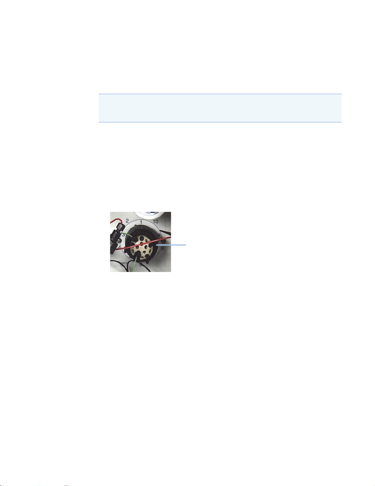
Replacing the Auxiliary Valve Pod
Black locking ring
The “pod” is the mechanical part of the auxiliary valve. Replacing the pod is easier and faster
than rebuilding the valve (see page 74).
Note If the auxiliary valve electronics require service, contact Thermo Fisher Scientific.
Electronics-related repair procedures must be performed by Thermo Fisher Scientific
personnel.
To replace the auxiliary valve pod
1. Turn off the pump flow from the Chromeleon ePanel.
2. Open the Dionex Aquion RFIC front door.
3. Disconnect each liquid line connected to the auxiliary valve.
4. Unscrew the black locking ring on the front of the valve (see Figure 26) and remove the
ring.
6
Service
Replacing the Auxiliary Valve Pod
Figure 26. Auxiliary valve locking ring
5. Grasp the front of the valve pod and pull firmly to remove it from the Dionex Aquion
RFIC.
6. Check that the new pod (6-port, P/N 061947; 10-port, P/N 061948) has the correct
number of ports for the valve being serviced.
7. Align the slots in the new pod with the runner in the valve holder on the Dionex Aquion
RFIC (see Figure 27). Valve pods are keyed to fit in one way only (one slot is narrower
than the other). Verify that the slots are aligned with their matching runners.
Thermo Scientific Dionex Aquion RFIC Operator’s Manual 75
Page 92

6
Valve pod
Slot (larger)
Runner (larger)
Splines
Valve holder
Splines
Service
Cleaning and Replacing the Pump Check Valves
Figure 27. Auxiliary valve pod and pod holder
8. Also verify that the two splines on the pod are aligned with the matching splines inside
the valve holder (see Figure 27). If necessary, twist the end of the pod to adjust the
position of the splines.
9. Push the pod into the holder until it clicks into place.
10. Replace the black locking ring on the valve.
11. Reconnect all liquid lines to the valve.
12. Turn on the pump flow. Check for leaks from the valve and tighten fittings as required
(see “Liquid Leaks” on page 60).
13. Close the front door.
Cleaning and Replacing the Pump Check Valves
A dirty check valve causes erratic flow rates and pressures. In addition, it may cause the pump
to lose prime and/or be difficult to reprime. If possible, replace check valves that are dirty. If
new check valves are not available, follow the instructions below to clean the valves.
To replace the check valves
1. Turn off the pump from the Chromeleon ePanel.
2. Turn off the Dionex Aquion RFIC main power switch.
3. To prevent contamination of pump parts, put on standard disposable laboratory rubber
gloves (powder-free, particle-free, and oil-free) before disassembling the pump head.
Note Never disassemble the pump head with bare hands. Even minute particles of
dust or dirt on the check valves or piston can contaminate the inside of the pump
head and result in poor pump performance.
4. Disconnect the tube fittings from the inlet and outlet check valve assemblies on the
primary pump head (see Figure 28).
76 Dionex Aquion RFIC Operator’s Manual Thermo Scientific
Page 93

6
Outlet check valve
Primary pump head
Secondary pump
head
Inlet check valve
Acorn nut
Inlet check valve
1/4-28 port
Inlet check valve
cartridge (double-hole
end visible)
Outlet check valve
10-32 port
Outlet check valve
cartridge (single-hole
end visible)
Flow
Flow
Service
Cleaning and Replacing the Pump Check Valves
Figure 28. Pump components
5. Using a 1/2-inch wrench, loosen both check valve assemblies. Remove the check valve
assemblies from the pump head.
Note The inlet check valve assembly housing has a 1/4-28 port. The outlet check valve
assembly housing has a 10-32 (smaller) port (see Figure 29).
Figure 29. Inlet and outlet check valve assemblies
6. If you are installing new cartridges (P/N 045994) in the existing check valve housings:
• When placing the cartridge in the inlet check valve housing, be sure the double-hole
end of the cartridge is visible (see Figure 29). If it is not, remove the cartridge from
the housing and install it correctly.
• When placing the cartridge in the outlet housing, be sure the single-hole end is visible
(see Figure 29). If it is not, remove the cartridge from the housing and install it
correctly.
IMPORTANT If you do not orient the check valve cartridges correctly, the pump will
not operate properly (and may be damaged). Liquid must enter the check valve
through the large single hole and exit through the small double holes.
Thermo Scientific Dionex Aquion RFIC Operator’s Manual 77
7. Install the inlet check valve assembly (P/N 045722) on the bottom of the primary pump
head.
8. Install the outlet check valve assembly (P/N 045721) on the top of the primary pump
head.
Page 94

6
Service
Replacing a Pump Piston Seal and Piston Rinse Seal
9. Tighten the check valves finger-tight, and then use a wrench to tighten an additional
one-quarter to one-half turn.
IMPORTANT Overtightening may damage the pump head and check valve housing
and crush the check valve seats.
10. Reconnect the liquid lines.
11. Close the front door.
12. Turn on the Dionex Aquion RFIC main power switch.
13. Prime the pump (see “Priming the Pump (Standard Procedure)” on page 90).
14. When the system is at operating pressure, check for leaks from the check valves. Tighten a
check valve a little more only if it leaks.
To clean the check valves
1. Carefully remove the check valve cartridges from the valve housings.
2. Place the check valve housings and cartridges in a beaker with methanol. Sonicate or
agitate the parts for several minutes.
3. Rinse each check valve housing and cartridge thoroughly with ASTM filtered, Type I
(18 megohm-cm) deionized water that meets the specifications listed in “Deionized
Water Requirements for IC” on page vi.
4. To reinstall the check valves and complete the procedure, see Step 6 through Step 14
above.
Replacing a Pump Piston Seal and Piston Rinse Seal
A damaged seal allows leakage past the piston, as well as leakage from the piston seal wash
housing. As a result, the pump may be difficult to prime, flow rates may be unstable, and
there may be baseline noise.
To prepare the pump for seal replacement
1. Rinse the pump flow path with ASTM filtered, Type I (18 megohm-cm) deionized water
that meets the specifications listed in “Deionized Water Requirements for IC” on page vi.
Direct the flow to waste by opening the waste valve on the secondary pump head (see
Figure 35). (To open the waste valve, turn the knob one-quarter to one-half turn
counterclockwise.)
2. After rinsing, close the waste valve.
3. Turn off the pump from the Chromeleon ePanel.
78 Dionex Aquion RFIC Operator’s Manual Thermo Scientific
Page 95

6
Service
Replacing a Pump Piston Seal and Piston Rinse Seal
To remove the pump head and piston
1. Turn off the Dionex Aquion RFIC main power switch.
2. To prevent contamination of pump parts, put on standard disposable laboratory rubber
gloves (powder-free, particle-free, and oil-free) before disassembling the pump head.
Note Never disassemble the pump head with bare hands. Even minute particles of
dust or dirt on the check valves or piston can contaminate the inside of the pump
head and result in poor pump performance.
3. Disconnect all tubing connections to the pump head.
4. Locate the open-end wrench (P/N 014605) provided in the Dionex Aquion RFIC Ship
Kit (P/N 064375). Use the wrench to remove the two acorn nuts from the pump head
(see Figure 28).
5. Slowly pull the head, allowing it to separate from the housing. Carefully disengage the
head from the piston by pulling the head straight off and away from its mounting studs.
CAUTION Lateral motion while disengaging the pump head from the
piston may break the piston.
MISE EN GARDE Un mouvement latéral pendant la séparation de la
tête et du piston peut casser le piston.
VORSICHT Vermeiden Sie Seitwärtsbewegungen, wenn Sie den Kopf
vom Kolben lösen. Andernfalls kann der Kolben brechen.
6. Place the head (front end down) on a clean work surface. Lift off the spacer to expose the
piston seal (for the primary pump head, see Figure 30; for the secondary pump head, see
Figure 31).
7. Hold the shaft of the piston (near the base), tilt the piston slightly, and pull the piston
away from the pump. The piston does not come off as part of the pump head assembly
because it is captured by a magnetic retention system.
Thermo Scientific Dionex Aquion RFIC Operator’s Manual 79
Page 96

6
Piston
(P/N 052840)
O-Ring
(P/N 055752)
Piston Seal
(P/N 055870)
Primary Pump Head
(P/N 055711)
Seal Guide
(P/N 058032)
Spacer with Drain
(P/N 057913)
Priming Valve Knob
(P/N 055709)
Inlet Check
Valve Assembly
(P/N 045722)
Outlet Check
Valve Assembly
(P/N 045721)
O-Ring
(P/N 059283)
Piston Rinse Seal
(P/N 048722)
O-Ring
(P/N 014895)
Piston
(P/N 052840)
Seal Guide
(P/N 058032)
O-Ring
(P/N 055752)
Piston Seal
(P/N 055870)
Secondary
Pump Head
(P/N 055712)
Spacer with Drain
(P/N 057913)
Waste Valve Knob
(P/N 055710)
O-Ring
(P/N 059283)
Piston Rinse Seal
(P/N 048722)
O-Ring
(P/N 014895)
Service
Replacing a Pump Piston Seal and Piston Rinse Seal
Figure 30. Primary pump head components
80 Dionex Aquion RFIC Operator’s Manual Thermo Scientific
Figure 31. Secondary pump head components
To install the new piston rinse seal
1. Remove the seal guide from the spacer to expose the piston rinse seal and O-ring. Remove
the O-ring.
2. Remove the old piston rinse seal from the seal guide:
a. Hold the seal guide with the flat side facing up.
b. To dislodge the piston rinse seal, gently insert the shaft of the piston through the
small hole in the center of the seal guide (see Figure 32).
Page 97

6
Service
Replacing a Pump Piston Seal and Piston Rinse Seal
Figure 32. Removing the piston rinse seal from the seal guide
c. Pull the seal off the end of the piston shaft and remove the piston from the seal guide.
3. Hold the new piston rinse seal (P/N 048722) with the grooved side facing up.
4. Using your fingertip, gently press the piston rinse seal into the seal guide until the edge of
the seal is below the surface of the seal guide.
IMPORTANT The piston rinse seal is made of soft plastic. Do not press on the seal
with anything hard or sharp, including your fingernail. If the seal is nicked or gouged,
it will not seal properly and may result in leaks.
5. Place the new O-ring (P/N 059283) into the groove in the seal guide.
6. Remove the O-ring from the groove in the flat side of the spacer and replace it with the
new O-ring (P/N 014895).
7. In one hand, hold the seal guide with the O-ring and piston rinse seal facing up (to
prevent the O-ring from falling out). In your other hand, hold the spacer with the cavity
facing down.
8. Gently press the seal guide into the cavity in the spacer until it is fully seated.
To remove the piston seal from the pump head
1. For the primary pump head: Install a 10-32 fitting plug (P/N 042772) in the outlet
check valve. Tighten the plug.
For the secondary pump head: Install a 10-32 fitting plug (P/N 042772) in both the
inlet and outlet ports. Tighten the plugs.
2. Close the priming valve.
3. Using a squirt bottle or a plastic syringe, fill the head cavity with deionized water through
the piston opening (see Figure 33). Use ASTM filtered, Type I (18 megohm-cm)
deionized water that meets the specifications listed in “Deionized Water Requirements for
IC” on page vi.
Thermo Scientific Dionex Aquion RFIC Operator’s Manual 81
Page 98

6
Piston
Pump head
Seal
Service
Replacing a Pump Piston Seal and Piston Rinse Seal
Figure 33. Filling the pump head cavity with deionized water
4. Reinsert the piston into the seal, and then push the piston into the head (see
Figure 34). This should hydraulically unseat the seal, causing it to pop out of the
head. When this occurs, remove the piston and pull off the seal.
5. If the seal does not pop out of the head, follow these steps:
a. Verify that the 10-32 fitting plugs in the inlet and outlet holes are tightened enough
to prevent any leaks from the pump head.
b. Fill the piston cavity with water and check for bubbles.
c. If there are no bubbles, repeat Step 4.
Figure 34. Removing the piston seal from the pump head
d
6. Remove the 10-32 fitting plug(s).
To install the new piston seal
1. Open the priming valve knob (primary pump head) or waste valve knob (secondary
pump head) by turning the knob one-quarter to one-half turn counterclockwise.
2. Push the piston through the spacer and then through the new seal. Insert the piston and
seal into the pump head until the seal makes contact with the bottom of the counterbore.
Note If necessary, lubricate the seal with a small amount of 0.2 micron filtered
82 Dionex Aquion RFIC Operator’s Manual Thermo Scientific
isopropyl alcohol to facilitate insertion.
Page 99

6
Service
Replacing a Pump Piston
3. To seat the seal, push down on the spacer until it is flush with the head. A clicking sound
indicates that the seal is correctly seated.
4. Close the priming valve knob or waste valve knob.
To reinstall the pump head and piston
Thermo Fisher Scientific recommends reinstalling the pump head and piston as a single
assembly. This allows the piston to center itself onto the magnetic follower.
1. Hold the assembled spacer and seal guide with the drain tubes aligned vertically and press
the spacer into the head until it is flush with the indented surface of the head.
2. Insert the piston so that 6 mm (1/4 inch) of the shaft is exposed. This ensures that the
magnet in the follower picks up the piston. (The follower is the cylinder that holds the
piston in place as it moves in and out of the pump head assembly.)
3. Reinstall the head and piston assembly. Use a wrench to tighten the nuts evenly (12 in-lb
torque).
To complete the procedure
1. Reconnect all liquid lines to the pump head.
2. Turn on the Dionex Aquion RFIC main power switch.
3. Prime the pump (see “Priming the Pump (Standard Procedure)” on page 90).
Replacing a Pump Piston
Continued leaking of the piston seal after installation of a new seal (assuming the pump head
is tight) indicates a dirty, scratched, or broken piston.
Follow the instructions in “Replacing a Pump Piston Seal and Piston Rinse Seal” on page 78
to install a new piston (P/N 052840) and piston seal (P/N 055870).
Replacing the Waste Valve or Priming Valve O-Ring
A damaged O-ring causes leakage around the base of the waste valve knob (on the primary
pump head) or priming valve knob (on the secondary pump head).
To replace the waste valve or priming valve O-ring
1. Turn off the pump from the Chromeleon ePanel.
2. Turn off the Dionex Aquion RFIC main power switch.
Thermo Scientific Dionex Aquion RFIC Operator’s Manual 83
Page 100

6
Waste valve
Priming valve
Valve Knob
O-Ring
(P/N 055752)
Service
Replacing the Waste Valve or Priming Valve O-Ring
3. To remove the waste valve or priming valve from the pump head: Turn the valve knob (see
Figure 35) counterclockwise until it is loose, and then pull the knob straight out of the
cavity in the pump head.
Figure 35. Pump waste valve and priming valve
4. If the O-ring is removed with the valve knob in Step 3, pull the O-ring off the end of the
knob (see Figure 36).
If the O-ring is not removed with the valve knob, carefully insert a thin object (for
example, the bent end of a paper clip) into the cavity in the pump head and pull out the
O-ring.
IMPORTANT Do not scratch the cavity. Scratches in the cavity will cause leaks
around the base of the knob while the pump is being primed.
Figure 36. Removing the waste valve or priming valve O-ring
5. Slide a new O-ring (P/N 055752) over the end of the valve.
6. To reinstall the valve, turn the knob clockwise and tighten finger-tight.
Note It is normal to encounter resistance after several rotations of the knob, as the
O-ring is being pushed into the cavity of the pump head.
7. Turn on the Dionex Aquion RFIC main power switch.
8. Prime the pump (see “Priming the Pump (Standard Procedure)” on page 90).
84 Dionex Aquion RFIC Operator’s Manual Thermo Scientific
 Loading...