

Page 1

Thermo Scientific Cryostat Microm Cryo Star HM 560
Thermo Scientific
Microtome Cryostat
Microm Cryo-Star HM 560
INSTRUCTION MANUAL
Microm International GmbH
part of Thermo Fisher Scientific
Robert-Bosch-Str. 49
69190 Walldorf / Germany
387 500 - English
1
Page 2

Thermo Scientific Cryostat Microm Cryo Star HM 560
2
Microm International GmbH
part of Thermo Fisher Scientific
Robert-Bosch-Str. 49
69190 Walldorf / Germany
387 500 - English
Page 3

Thermo Scientific Cryostat Microm Cryo Star HM 560
CERTIFICATION
Thermo Fisher Scientific Microm International GmbH certifies that this instrument
has been tested and checked carefully. Its technical data was verified before
shipment to be in accordance with the published specifications.
The instrument complies with applicable international safety regulations.
WARRANTY
This Thermo Fisher Scientific product is warranted against defects in material and
workmanship for a period of 1 year. Parts which prove to be defective during the
warranty period will be repaired or replaced free of charge by the manufacturer. No
other warranty is expressed or implied. Unauthorized modification or repair by third
party persons will void the warranty.
The warranty will expire in case of improper or wrong use of the instrument and in
case the warning and precautionary messages are not observed. Thermo Fisher
Scientific is not liable for any occurring damage.
Errors and omissions excepted. Subject to amendment and improvement without
further notice.
This instruction manual will be supplied together with each instrument. Further
copies can be ordered at the nearest Thermo Fisher Scientific sales office by giving
the serial number of the instrument, the number of the instruction manual and the
date of issue.
This instruction manual is available in the following languages:
Cat. No.
German: 387 490
English: 387 500
French: 387 510
Microm International GmbH
part of Thermo Fisher Scientific
Robert-Bosch-Str. 49
69190 Walldorf / Germany
387 500 - English
3
Page 4

Thermo Scientific Cryostat Microm Cryo Star HM 560
INTENDED USE
Dear valued Customer,
Thank you for buying this Thermo Fisher Scientific instrument.
Before putting the instrument into operation, please read these operating
instructions carefully to familiarize you with its proper operation and
functions.
Only skilled or specially trained personnel must operate the microtome
cryostat HM 560, i.e. clamping the specimen, trimming, sectioning and taking
off the sections from the instrument. The listed and marked safety measures
as well as the regulations and hygiene measures of your respective lab must
strictly be observed.
Serial No.: __________________
Please check the Serial No. on the type plate, which is placed on the rear
side of your instrument and enter this number here. This way, questions and
service can be handled faster.
Instruction Manual No. 387500
Issued on February 03rd, 2009
Microm International GmbH
part of Thermo Fisher Scientific
Robert-Bosch-Strasse 49
69190 Walldorf
Germany
Phone: +49.(0)6227.836-0
Fax: +49.(0)6227.836-111
Email: info.dxd.dewal@thermofisher.com
Internet: www.ap-walldorf.com
4
Microm International GmbH
part of Thermo Fisher Scientific
Robert-Bosch-Str. 49
69190 Walldorf / Germany
387 500 - English
Page 5

Thermo Scientific Cryostat Microm Cryo Star HM 560
Intended Use
Table of Contents
Safety Precautions
PART 1 INTRODUCTION
1-1 Description of the Cryo-Star HM 560
1-2 Technical data Cryo-Star HM 560
PART 2 OPERATING INSTRUCTIONS
2-1 Setting up the cryostat
2-2 Initial turn-on
2-3 Basic operational rules
2-4 Setting section thickness and trimming thickness
2-5 Specimen and knife cooling
2-5-1 Actual and set value of the specimen temperature
2-5-2 Actual and set value of the knife temperature
2-5-3 Function fast freezing
2-5-4 Programming temperature parameters
2-6 Cutting movement and retraction
2-7 Feed
2-7-1 Knife carrier coarse feed
2-7-2 Speed of the knife carrier coarse feed
2-7-3 Automatic approach system
2-7-4 Trimming and first cuts
2-7-5 Fine feed
2-8 Setting the cutting window
2-9 Hand wheel brake
2-10 Detaching the specimen
2-11 Indication of cutting processes
2-11-1 Section counter
2-11-2 Section thickness sum
2-11-3 Remaining travel to front end position
2-11-4 Real time
2-12 Setting the real time, WAKE time and ACTIVE time
2-12-1 Setting the real time
2-12-2 Setting the WAKE time
2-12-3 Setting the ACTIVE time
Microm International GmbH
part of Thermo Fisher Scientific
Robert-Bosch-Str. 49
69190 Walldorf / Germany
387 500 - English
5
Page 6

Thermo Scientific Cryostat Microm Cryo Star HM 560
2-13 Defrosting
2-13-1 Setting the defrost time
2-13-2 Defrosting cycle
2-13-3 Interrupting a defrosting cycle
2-14 Turning off the function retraction
2-15 Customer-specific settings
2-15-1 Setting the contrast
2-15-2 Selecting the language
2-16 Turning off the cooling function
2-17 Illumination of the cooling chamber
2-18 Adjusting the operating panel
2-19 Specimen holder, freezing-on and specimen orientation
2-19-1 Specimen holder, freezing-on
2-19-2 Specimen orientation
2-20 Knife carriers
2-20-1 Standard knife carrier SM
2-20-2 Disposable blade holder SE
2-20-3 Modification from standard knife carrier SM to disposable blade holder SE
2-21 Error code indication
2-21-1 Definition of the error codes
2-22 Accessories
2-22-1 Standard equipment
2-22-2 Additional equipment
PART 3 Theory of operation
3-1 Specimen and knife carrier cooling, defrost cycle
3-2 Cutting movement
3-3 Knife carrier coarse feed and trimming stages
3-4 Automatic approach system
PART 4 Working with the cryostat
4-1 Preparations on the microtome and inside the cooling chamber
4-2 Freezing on the specimen
4-4 Orientation and trimming of specimens
4-5 Sectioning and taking off sections
4-6 How to avoid malfunctions
6
Microm International GmbH
part of Thermo Fisher Scientific
Robert-Bosch-Str. 49
69190 Walldorf / Germany
387 500 - English
Page 7

Thermo Scientific Cryostat Microm Cryo Star HM 560
PART 5 Maintenance of the cryostat
5-1 Shutting-off for cleaning
5-2 Cleaning and care of the microtome
5-3 Changing the fluorescent lamp
5-4 Disposal of the instrument after final shutdown
Microm International GmbH
part of Thermo Fisher Scientific
Robert-Bosch-Str. 49
69190 Walldorf / Germany
387 500 - English
7
Page 8
Thermo Scientific Cryostat Microm Cryo Star HM 560
SAFETY PRECAUTIONS
WARNING SIGNALS AND SYMBOLS
The installation and routine use of the Cryo-Star HM 560 is easy and safe if the instructions in this manual are
being observed.
However, the situations which might be risky for the personnel or equipment are specially marked in this
manual with the following symbols and messages.
Note:
Special instructions regarding operation of the instrument.
Caution:
Special precautionary measures to prevent damage to equipment. For a long lifetime of the
equipment, please observe these instructions carefully.
Danger:
Special warning messages to prevent harm to persons and/or serious damage to equipment. For
your own safety, please observe these instructions carefully.
Biohazard:
Warning of biological danger.
Separate taking back of electrical and electronic instruments in the countries of the
European Union:
This is to be applied in the countries of the European Union and other European countries with a
separate collecting system within the waste management.
This product, being an electro and/or electronic instrument, must be treated separately within the
waste management process (WEEE).
8
Microm International GmbH
part of Thermo Fisher Scientific
Robert-Bosch-Str. 49
69190 Walldorf / Germany
387 500 - English
Page 9
Thermo Scientific Cryostat Microm Cryo Star HM 560
SAFETY PRECAUTIONS
A T T E N T I O N !
The operator's safety is affected, when the instrument is not operated in
accordance with this instruction manual.
Please observe the following general precautions during operation of this
instrument. Failure to comply with these precautions violates safety standards and
the intended use of the instrument. Thermo Fisher Scientific is not liable for misuse
of the instruments and failure to comply with basic safety requirements.
INSTRUMENT GROUNDING
To avoid injury from electrical current, the instrument must be connected with the safety ground. The
instrument is equipped with a three wire ground plug. The power outlet must be connected to the safety
ground and must meet the International Electrotechnical Commission (IEC) regulations.
CAUTION: MAINS VOLTAGE
Never remove instrument covers during operation. Component replacements as well as adjustments must
only be made by trained service personnel. Unplug the unit before removing or opening the covers.
DANGER IN EXPLOSIVE ENVIRONMENT
The instrument must not be operated in the presence of flammable gases.
HAZARD OF FROSTBITE
Avoid permanent touching of metal parts inside the cryostat microtome chamber as frostbite may occur at
unprotected hands and arms.
HAZARD OF RADIOACTIVE RADIATION
When working with radioactive specimens observe all applicable radiation safety procedures. When working
with radioactive contaminated material, appropriate safety and disinfection measures must be carried out.
According to the rules and regulations concerning the handling of radioactive contaminated material of the
respective laboratory, safety clothing (e.g. particle mask, gloves, protective shoe covers) must be worn.
Radioactive contaminated waste must be disposed of according to the respective regulations.
Microm International GmbH
part of Thermo Fisher Scientific
Robert-Bosch-Str. 49
69190 Walldorf / Germany
387 500 - English
9
Page 10

HAZARD OF INFECTION
Thermo Scientific Cryostat Microm Cryo Star HM 560
Use the appropriate safety and disinfection measures when working with infectious specimens.
According to the rules and regulations concerning the handling of infectious/radioactive contaminated
material of the respective laboratory, safety clothing (e.g. particle mask, gloves, protective shoe covers) must
be worn.
HAZARD OF BIOLOGICAL DANGER
Specimens used during the intended operation of the instrument might potentially be infectious. For this
reason, it is recommended to observe the general laboratory regulations concerning protection against
danger of infection.
Information on decontamination media, their use, dilution and effective range of application can be read in the
Laboratory Biosafety Manual : 1984 of the World Health Organization.
CAUTION: DANGER OF SQUEEZING
When placing the microtome cryostat HM 560 onto the height adjustable stage, it is absolutely necessary that
the stage is in its upper position or in case of a mechanical stage that the rear wall will be removed. Not
observing this leads to the risk of squeezing your hands between the rear carrying handles and the stage
housing.
HAZARD OF MALFUNCTION
To avoid the hazard of malfunction of an instrument, it must only be operated in a controlled electromagnetic
environment. This means, that transmitters such as mobile phones must not be operated in their close
vicinity.
CARE IN USING MICROTOME KNIFE
To diminish the danger of being injured by the knife or blade, use the knife guard when adjusting
specimen and knife. If possible, the specimen should be clamped in before the knife is inserted
into the knife holder. Before changing the knife holder, always remove blade or knife! Unused
knives should always be kept in a knife case. Never place the knife with the cutting edge upwards.
Never try to catch a dropping knife!! Never check the sharpness of the cutting edge with your fingers. The
cutting edge is extremely sharp!
WASTE DISPOSAL
All debris, waste as well as infectious and radioactive contaminated material from operation must be
disposed of in accordance with the respective regulations of the lab. Disinfection and cleaning liquids as well
as section waste must be disposed of according to the respective regulations for special waste!
10
Microm International GmbH
part of Thermo Fisher Scientific
Robert-Bosch-Str. 49
69190 Walldorf / Germany
387 500 - English
Page 11
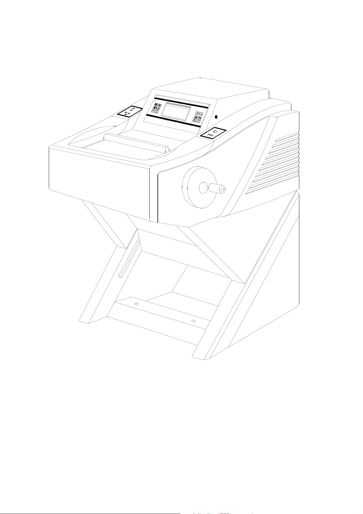
Thermo Scientific Cryostat Microm Cryo Star HM 560
Fig. 1
Microm International GmbH
part of Thermo Fisher Scientific
Robert-Bosch-Str. 49
69190 Walldorf / Germany
387 500 - English
11
Page 12

Thermo Scientific Cryostat Microm Cryo Star HM 560
1 INTRODUCTION
1-1 DESCRIPTION OF THE
CRYO-STAR HM 560
Open top cryostat. Modular design. Stainless
steel cooling chamber. Temperature regulation
variable down to -50°C for specimen holder
and down to -35°C for knife carrier. Graphic
LC-display of preset and actual temperatures,
electronic control with user-oriented touchpad
keyboard, battery-buffered memory and selfdiagnostic system. Standby and sleep status
for noise reduction and energy savings.
Automatic evaporator defrosting and in addition
a manual defrost cycle which can be activated
when needed. Defrost interrupt on keystroke
request. Integrated rapid freezing device with
controlled cooling element down to -60°C.
Freezing device temperature independent of
cryo-chamber temperature. Detach function to
remove used specimen from specimen chucks.
Sliding window with heater and integrated,
position adjustable fluorescent lamp for cryochamber. Storage space inside the cryochamber. Flat storage space on top of the
housing.
HM-Rotary Microtome with backlash and
maintenance-free cross roller bearings in
stainless steel. Electro-motorized feed system.
Section thickness setting from 0,5 to 100
microns;
up to 2 µm in 0,5 µm-increments,
up to 10 µm in 1 µm-increments,
up to 20 µm in 2 µm-increments,
up to 50 µm in 5 µm-increments and
up to 100 µm in 10 µm-increments.
Trimming thickness setting from 5 to 500
microns;
up to 10 µm in 5 µm-increments,
up to 100 µm in 10 µm-increments,
up to 200 µm in 20 µm-increments and
up to 500 µm in 50 µm-increments.
Specimen retraction during the return stroke
with optical indication. Horizontal feed range 48
mm. Vertical specimen stroke 60 mm. Max.
specimen size 75 x 55 mm.
Motorized coarse feed in two directions with
three speed selections. Limit indication and
automated switch off at front and rear limits of
horizontal travel. Automatic approach system
for exact and safe approach of specimen
towards the knife edge.
Section counter and indication of sum of
section thicknesses with reset-button.
Indication of remaining travel. Hand wheel
brake in any position. Fine orientation of
specimen on two axes. Rotatable on Z-axis,
360°.
Basic outfit with three specimen chucks, cryocompound, 100 ml cryostat oil, brush shelf and
section waste tray.
A multi-use knife carrier is available. The
standard knife carrier is designed so the knives
as well as the disposable blade holder can be
easily clamped in place and adjusted.
Depending on the version, the disposable
blade holders SE take up low or high profile
blades. The corresponding anti-roll guides
facilitate taking off sections.
12
MICROM International GmbH
Robert-Bosch-Str. 49
D- 69190 Walldorf
387 500 - English
Page 13

Thermo Scientific Cryostat Microm Cryo Star HM 560
1-2 TECHNICAL DATA CRYO-STAR HM 560
Specimen temperature control: .......................................................................... +10°C to -50°C
Knife carrier control: ................................................................................ -10°C to -35°C
Fast freezing station: ................................................................................. down to -60°C
Defrosting: automatic defrosting, adjustable with temperature control
manual immediate defrosting
Microtome: Section thickness range: ............................................. 1 - 500 µm
Fine section thickness range: .................................... 0,5 - 100 µm
Resolution: .................................................. 0,5 µm for 0,5 - 2 µm
.......................................................................... 1 µm for 2 - 10 µm
........................................................................ 2 µm for 10 - 20 µm
........................................................................ 5 µm for 20 - 50 µm
.................................................................... 10 µm for 50 - 100 µm
Trimming thickness range: ........................................... 5 - 500 µm
Resolution: ........................................................ 5 µm for 5 - 10 µm
.................................................................... 10 µm for 10 - 100 µm
.................................................................. 20 µm for 100 - 200 µm
.................................................................. 50 µm for 200 - 500 µm
Knife carrier retraction during return travel ...........................40 µm
Horizontal knife carrier range ............................................ 48 mm
Vertical specimen stroke ................................................... 60 mm
Read-outs: Graphical LC display: section thicknesses, section counter, sum of
section thicknesses, remaining travel to front end position, size of
the cutting window
Specimen approach: .......................................................................... automatic function
........................................ alternatively manual with variable speed
Temperature parameter: ............................... temperature set values can be stored in pairs
Size of chucks: .......................................................................................30, 40 mm
............................................................. special sizes upon request
Specimen orientation: x - and y - axes: ......................................................... universal 8°
z - axis: ......................................................................... up to 360°
Coarse feed: ........................................... motorized, graduated and continuous
Cooling chamber illumination: ................................................ with variable illumination position
Sliding window: ............................................................................................. heated
Cutting speed: .................................................................................. 0 - 250 mm/s
Hand wheel brake: ................................................................................. in any position
All temperatures refer to an ambient temperature of +20°C!
Cont'd on page -2-
MICROM International GmbH
Robert-Bosch-Str. 49
D- 69190 Walldorf
387 500 - English
13
Page 14

Thermo Scientific Cryostat Microm Cryo Star HM 560
1-2 TECHNICAL DATA CRYO-STAR HM 560
Storage
temperature range: ......................................................................... -20°C up to +50°C
Operating conditions: ....................... +5°C up to +35°C (at a max. rel. humidity of 60%)
........................................................... altitude up to 2000 m M.S.L.
.......................................................................... for indoor use only
Power requirements: ....................................................... 100 V 12 A +/-10% 50...60 Hz
............................................................... 115 V 12 A +/-10% 60 Hz
................................................. 220...230 V 6 A +/-10% 50...60 Hz
................................................................. 240 V 6 A +/-10% 50 Hz
Pollution degree: ...................................................................................................... 2
Overvoltage category: ...................................................................................................... II
Acoustic pressure: ......................................................................................... 45 dB(A)
............................... measured with 1 m distance to the instrument
Dimensions: .. Wide (w/o Hand wheel): 769 mm, deep: 932 mm, high: 578 mm
Weight: ............................................................................................. 141 kg
All temperatures refer to an ambient temperature of +20°C!
page -2-
14
MICROM International GmbH
Robert-Bosch-Str. 49
D- 69190 Walldorf
387 500 - English
Page 15
Thermo Scientific Cryostat Microm Cryo Star HM 560
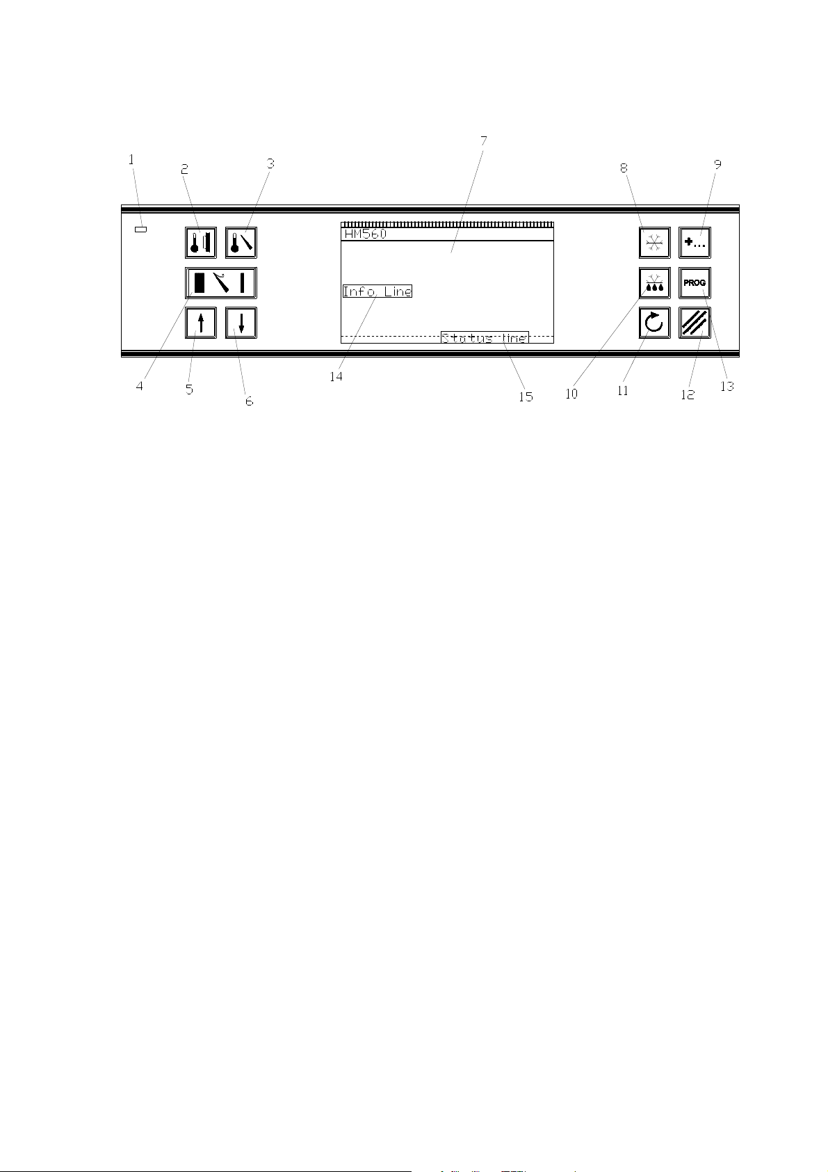
1 = On indication (sleep status)
2 = Button specimen temperature
3 = Button knife temperature
4 = Button TRIM/FEED
5 = Button UP
6 = Button DOWN
7 = LC display
8 = Button fast freezing
Fig. 2
9 = Button options
10 = Button detaching
11 = Scroll button
12 = Button RESET
13 = Button PROG
14 = Info line
15 = Status line
MICROM International GmbH
Robert-Bosch-Str. 49
D- 69190 Walldorf
387 500 - English
15
Page 16
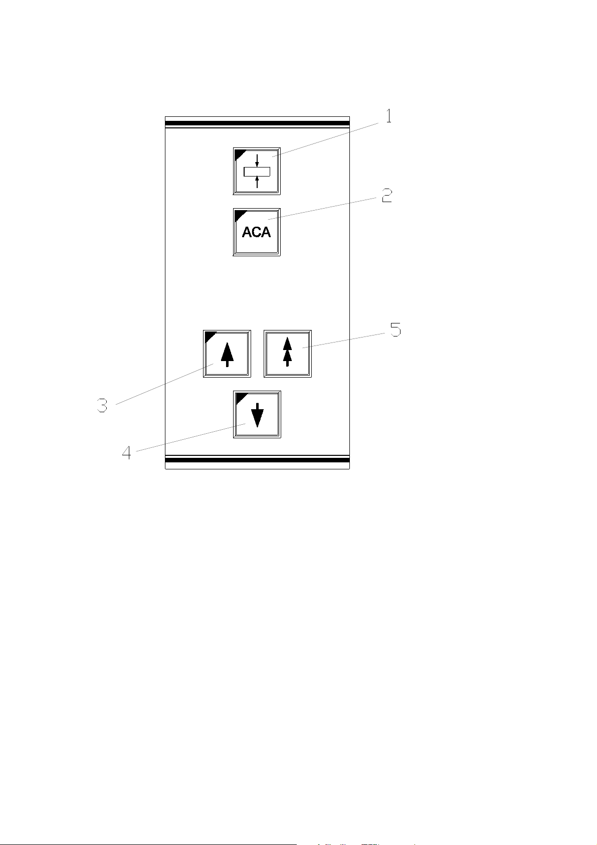
Thermo Scientific Cryostat Microm Cryo Star HM 560
1 = Button cutting window
2 = Button ACA
3 = Button coarse feed, forwards
4 = Button coarse feed, backwards
5 = Button TRIM
16
MICROM International GmbH
Robert-Bosch-Str. 49
D- 69190 Walldorf
387 500 - English
Fig. 3
Page 17
Thermo Scientific Cryostat Microm Cryo Star HM 560
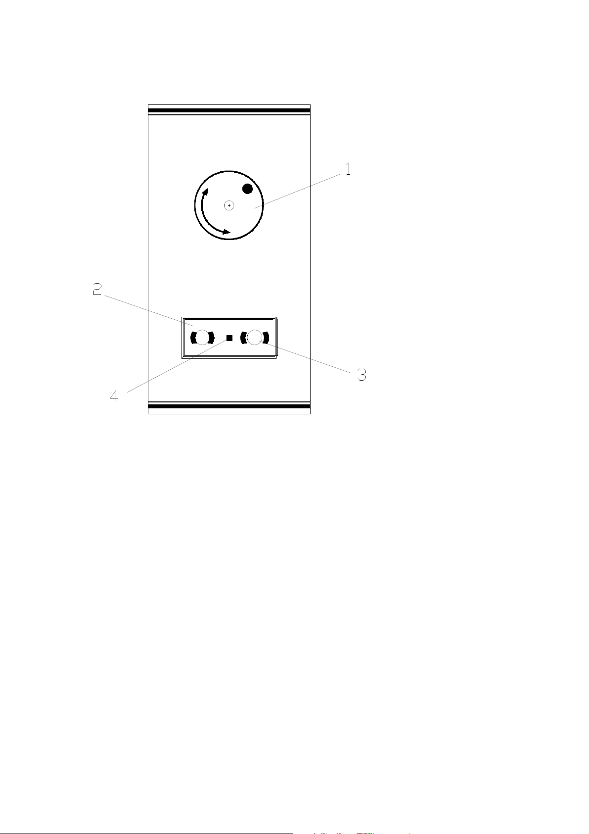
1 = Symbol Hand wheel
2 = Button to activate the Hand wheel brake
3 = Button to loosen the Hand wheel brake
4 = Brake LED
Fig. 4
MICROM International GmbH
Robert-Bosch-Str. 49
D- 69190 Walldorf
387 500 - English
17
Page 18
Thermo Scientific Cryostat Microm Cryo Star HM 560
2 OPERATING INSTRUCTIONS
2-1 SETTING UP THE CRYOSTAT
Note:
If the microtome cryostat is supplied
with an extra height-adjustable stage,
first unpack and set up this stage
according to the separate instruction manual.
Unpacking the instrument:
• Loosen and remove the four tightening
straps.
• Lift and remove the wooden top of the
packing.
• Remove the foam parts upwards.
• The four side parts of the packing, which are
connected with each other, can now be
removed upwards.
• Slightly tilt the cryostat to the side and
remove the right and left lower foam parts
one after the other.
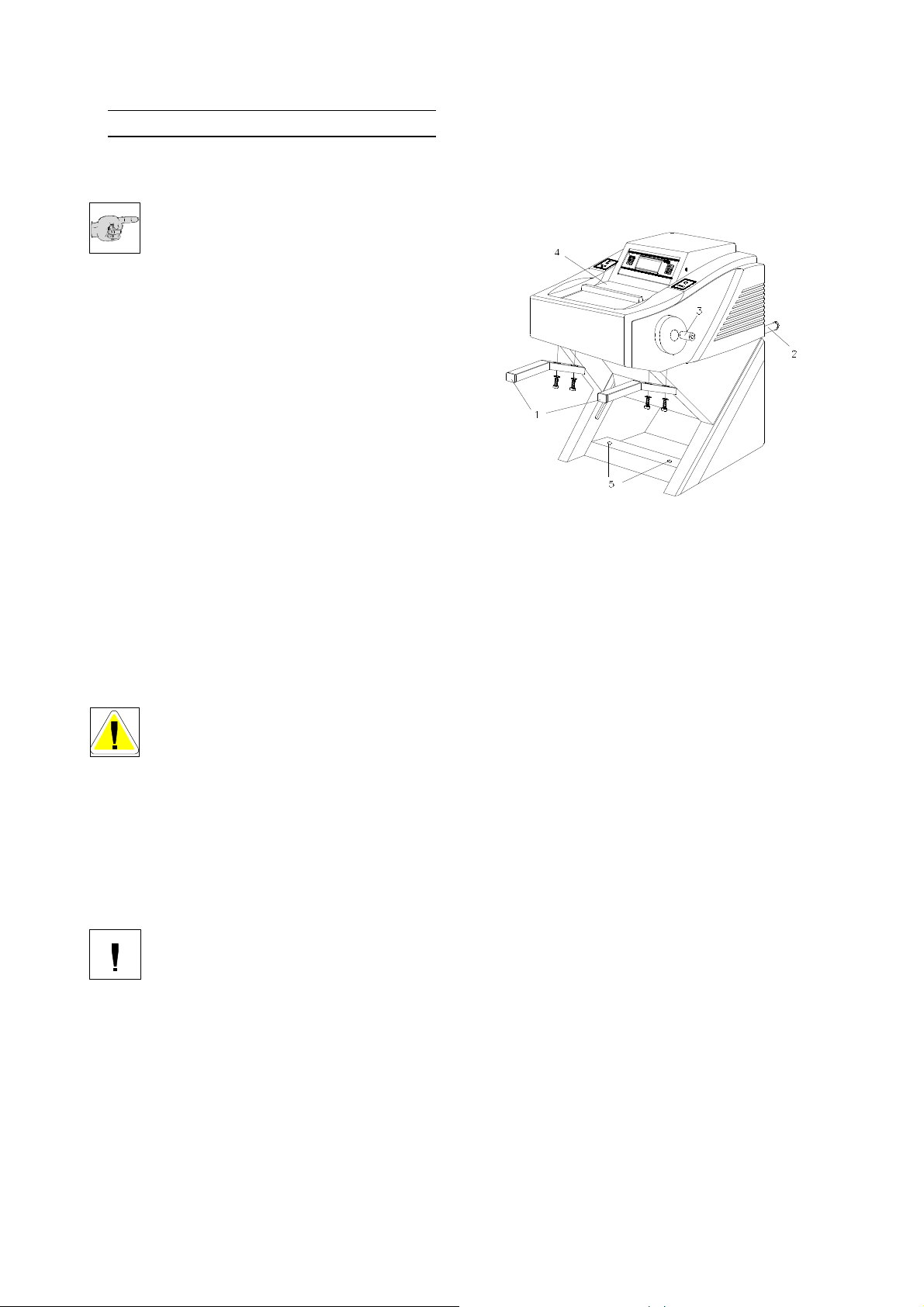
• Lift the cryostat by the carrying handles (fig.
5.1 and 5.2) from the pallet.
• In case the handles are not installed, securely
install the attached carrying handles (fig. 5.1
and 5.2) at the front and rear side of the
instrument and carry the instrument to the
site of installation (table according to the
customer's choice) or place it onto the heightadjustable stage.
Danger:
When placing the microtome cryostat
HM 560 onto the height adjustable
stage, it is absolutely necessary that
the stage is in its upper position.
Not observing this leads to the risk of
squeezing your hands between the rear
carrying handles and the stage housing.
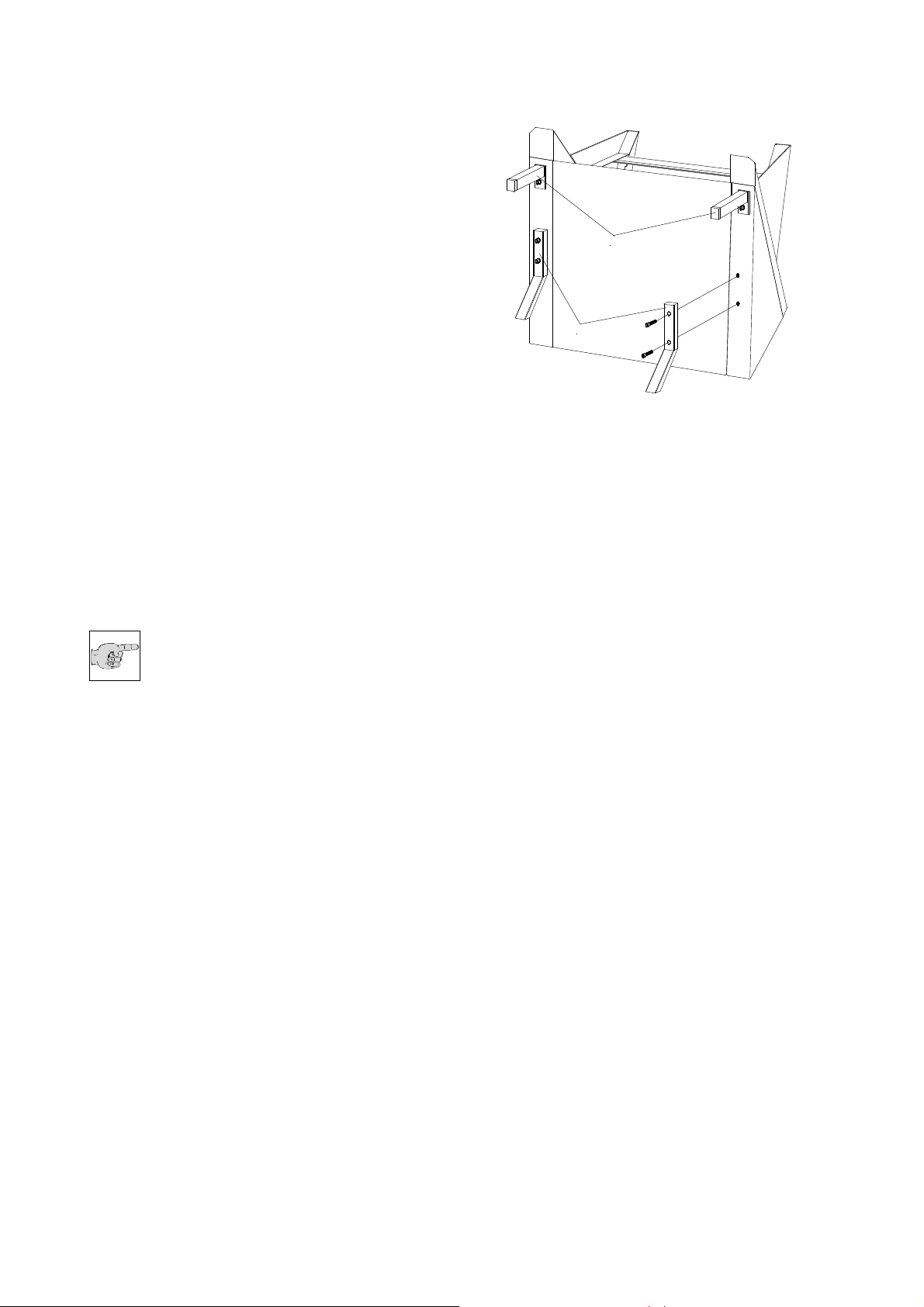
• Remove the handles (fig. 5.1 and 5.2).
cryostat, as when lowering the heightadjustable stage, the handles will hit the stage
and cause damage to the stage.
Caution:
Before the initial set-up of the height-
adjustable stage, it is absolutely
necessary to dismount the two rear
carrying handles (fig. 5.2) on the
Fig. 5
18
MICROM International GmbH
Robert-Bosch-Str. 49
D- 69190 Walldorf
387 500 - English
Page 19
Thermo Scientific Cryostat Microm Cryo Star HM 560
• Adjust the handles of the cryostat (fig. 5a.1
and 5a.2) on the rear side of the cryostat
stage.
• Carefully keep the shipping container for
possible return shipments.
Choose installation site that
• enough ventilation for the cooling system is
guaranteed.
• the distance between wall and rear panel is
approx. 10 - 15 cm.
• the suction areas on either side are kept free.
Moreover, the installation site must be free
from:
• draught by open doors or by air conditioning
systems.
• direct exposure to sunlight into the cooling
chamber.
Note:
Both measures reduce the formation of
frost and therefore result in more
favourable work conditions. A high air
moisture as well as high ambient temperatures
reduce the maximum performance of the
instrument.
In case the instrument is equipped with the
height-adjustable stage, turn the screws (fig.
5.5) on the front foot ends to fix the complete
unit.
Afterwards:
• Install the attached Hand wheel handle (fig.
5.3).
1
2
Fig. 5a
MICROM International GmbH
Robert-Bosch-Str. 49
D- 69190 Walldorf
387 500 - English
19
Page 20
Thermo Scientific Cryostat Microm Cryo Star HM 560
2-2 INITIAL TURN-ON
As already mentioned in part 2-1, the heightadjustable stage, if equipped, must be set up
according to the separate instruction manual
before the initial turn-on of the microtome
cryostat.
Caution:
Before turning on the instrument for the
first time, please check if the power
requirements indicated on the type
plate (fig. 7) correspond to the power supply
voltage being used.
• No other instruments should be connected to
the circuit used for the cryostat, as the
compressor needs high surge currents when
started.
• Do not use multi-socket power outlets and
extension lines for the supply of the stage.
• Connect the power line of the instrument to
the power outlet.
• Turn on the power switch (fig. 6.1) on the rear
side of the instrument.
• Close the heated sliding window (fig. 5.4) and
cool down the instrument.
Note:
To avoid frost built-up on the
specimen, the specimen temperature
is controlled to a temperature of +10°C
until the knife has reached a temperature
of -10°C.
The cooling phase will take approx. 1 to 2 h
depending on the set knife temperature
between -15°C and -30°C.
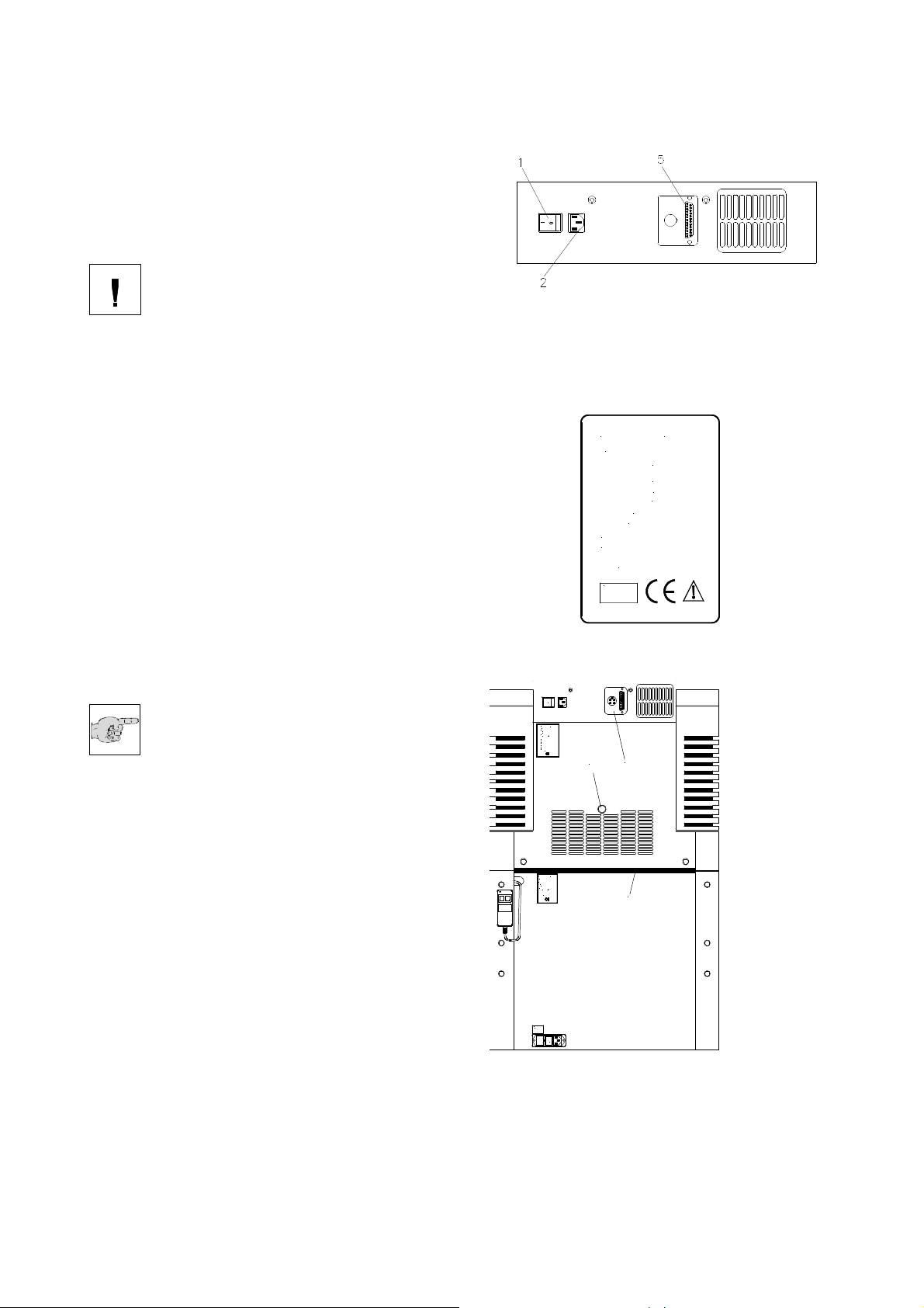
1 = Power switch
2 = Mains plug
5 = Socket for option Vacutome/Disinfection
MICROM
69190 Walldorf, Germany
GmbH
Type HM 560V
Ser. No.XXXXX
Cat. No. 956320
220...230V 6A 50...60Hz
Cooling System
Refr.: R 404a
Amount: 0,275 kg
Max. Press.: 2300 kPa
Made in Germany
I V D
I
0
GmbH
MICROM
69190 Walldorf, Germany
Type HM 560 MV
Ser. No.____
Cat. No. ______
__A / ___ V + 10% __Hz
Fuse 2 x __AT
HP Circuit
Refr.: R 134a
Amount: 0,180kg
Max. Press.: 2300kPa
LP Circuit
Refr.: R 404a
Amount: 0,270kg
Max. Press.: 2300kPa
Made in Germany
1
4
GmbH
MICROM
69190 Walldorf, Germany
Type Stage f. HM 560 HV
Ser. No. __ __
Cat. No. ______
_A /___V +10% __Hz
Fuse 2x __AT
Made in Germany
3
Fig. 6
Fig. 7
20
~___V
F1/F2
2x __AT
MICROM International GmbH
Robert-Bosch-Str. 49
D- 69190 Walldorf
387 500 - English
I
0
Fig. 8
Page 21
Thermo Scientific Cryostat Microm Cryo Star HM 560
2-3 BASIC OPERATIONAL RULES
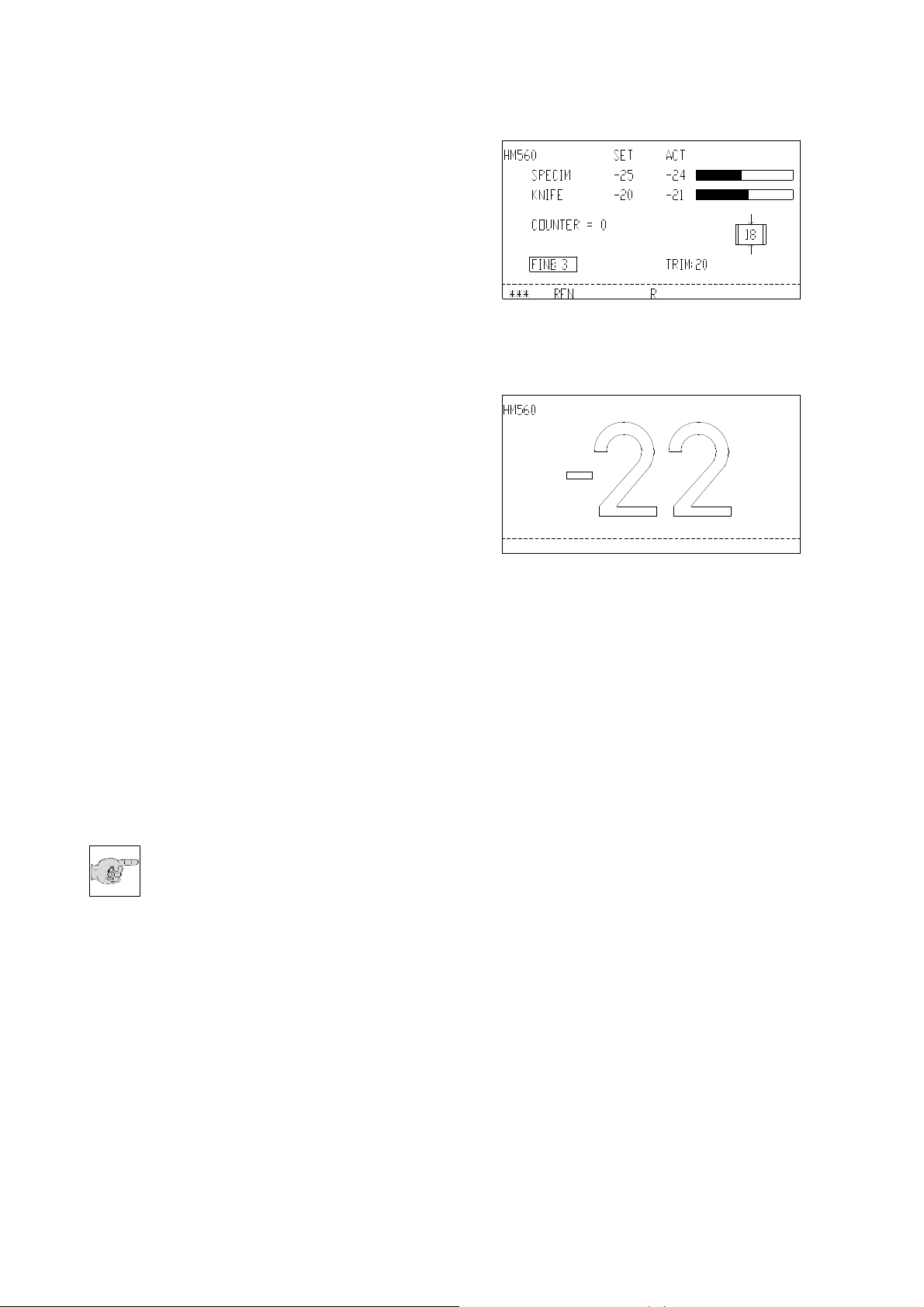
When turning on the instrument, the
display shows:
• the configuration of the instrument
• the section thickness selection
• the specimen and knife temperatures with the
corresponding set and actual values
• the symbol for the cutting window
This is the display (fig. 9) while the instrument
is in its active status.
To save energy and extend the lifetime of
some instrument components, the instrument
has two more operative status:
• Standby status
• Sleep status
The instrument switches to the standby status
when it is turned on, but not operated for more
than a pre-selected active time (see part 2-12-
3) between 1 and 9 h. The chamber
illumination goes off and the display (fig. 10)
switches to a large indication of the knife actual
temperature. This is the clear sign for the
standby status and gives the operator
information on the knife temperature, also from
a greater distance.
When the instrument is not operated for
another hour, the cryostat switches to the
sleep status. The display illumination goes off.
However, the equipment-on indicator (fig. 2.1)
then lights up and shows that the instrument is
still on.
Note:
While in the sleep status, the
temperature control of the knife
temperature features a reduced control
accuracy.
The specimen temperature in the sleep status
is always kept at -15°C. The set temperature of
the knife carrier is kept constant.
This does not only save energy, but also
reduces the formation of frost on the specimen
clamping.
Fig. 9
Fig. 10
MICROM International GmbH
Robert-Bosch-Str. 49
D- 69190 Walldorf
387 500 - English
21
Page 22
Thermo Scientific Cryostat Microm Cryo Star HM 560
• To return to the active operating state, press
any key on the control panels, move the
Hand wheel or wait until the WAKE time (see
2-12-2) has been reached.
The WAKE time is used to trigger the
instrument back into the active state.
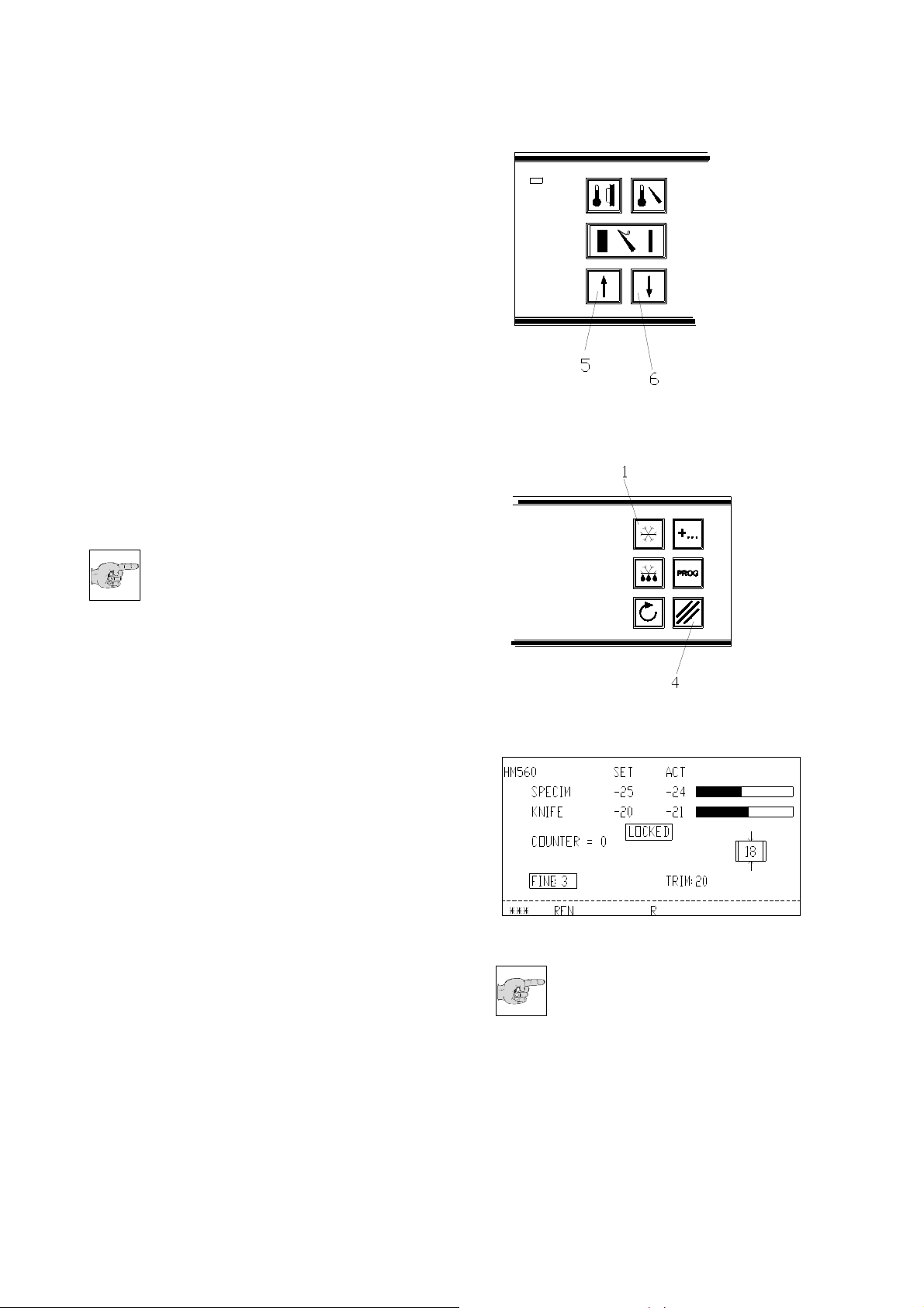
UP/DOWN buttons
These two buttons (fig. 11.5 and 11.6) are
used to change pre-selected values of different
kinds in connection with the chosen function.
• section thickness
• trimming thickness
• specimen temperature
• knife temperature
• time settings
Note:
To operate the instrument easily and
comfortably with a few buttons only,
please note the following:
After having chosen a function, its pre-selected
values can be changed via the UP or DOWN
buttons.
However, if no entry is made within 2 seconds,
the operating control switches back into its
basic status.
RESET-button
This button (fig. 12.4) is used to reset added
values (e.g. number of sections, sum of section
thicknesses) to zero. In some cases, this
button is used as additional button for doublebutton functions (see part 2-8 and
2-13-3).
Keyboard lock
To lock the keyboards and to block the feed
movement, press the buttons (fig. 12.4 and
12.1) for approx. 2 sec. The display (fig. 12a)
shows LOCKED.
To unlock the keyboards press the buttons (fig.
12.4 and 12.1) again.
Fig. 11
Fig. 12
Fig. 12a
Note:
When the keyboards have been
locked, this leads automatically
after 5 sec. to the standby status and after
another 5 sec. to the sleep status.
22
MICROM International GmbH
Robert-Bosch-Str. 49
D- 69190 Walldorf
387 500 - English
Page 23
Thermo Scientific Cryostat Microm Cryo Star HM 560
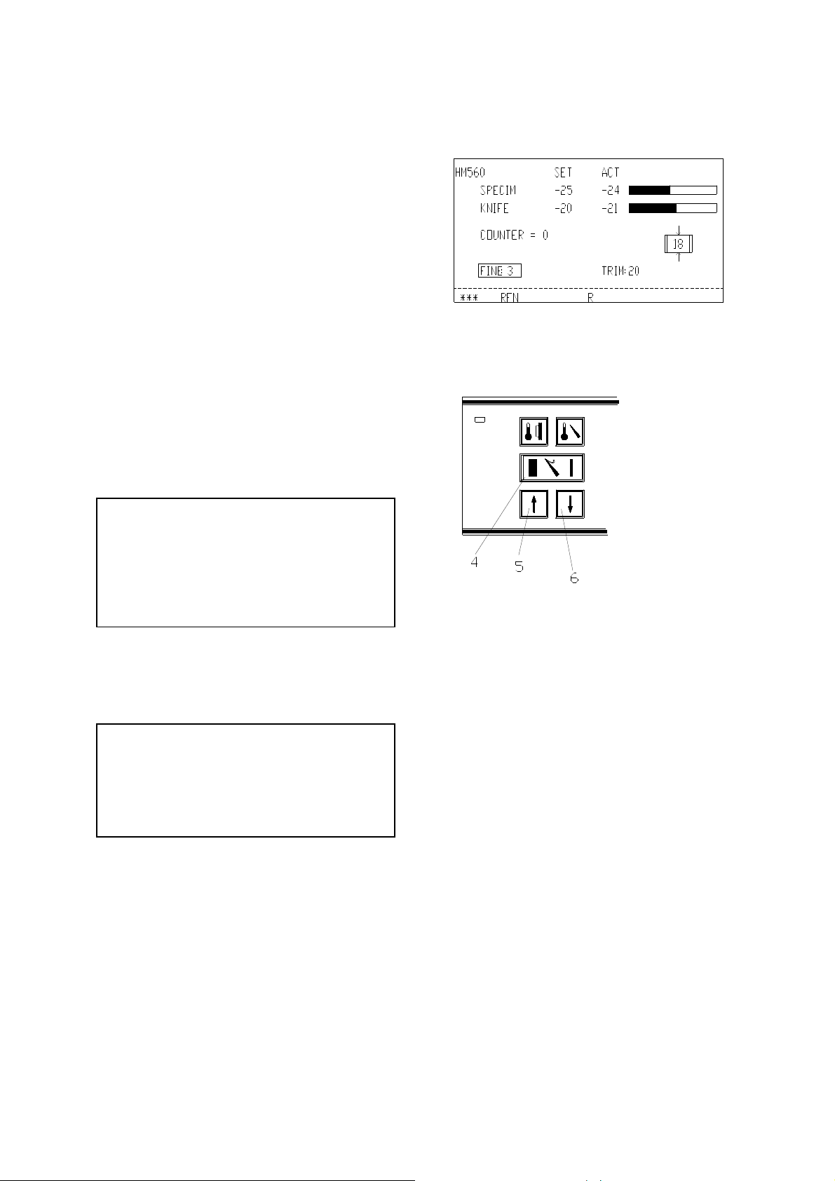
2-4 SETTING SECTION THICKNESS
AND TRIMMING THICKNESS
Basic status of the operating control:
To choose between section thickness and
trimming thickness
• press button (fig. 14.4).
• The selected setting is shown inverted on the
display.
• Then enter the desired section or trimming
thickness via button UP (fig. 14.5) or DOWN
(fig. 14.6).
• The changed values are shown on the
display.
The graduation of the section thicknesses
(which can be pre-selected) is divided into 5
ranges:
range graduation
from 0,5 µm to 2 µm 0,5 µm
from 2 µm to 10 µm 1 µm
from 10 µm to 20 µm 2 µm
from 20 µm to 50 µm 5 µm
from 50 µm to 100 µm 10 µm
The graduation of the trimming thicknesses
(which can be pre-selected) is divided into 4
ranges:
range graduation
from 5 µm to 10 µm 5 µm
from 10 µm to 100 µm 10 µm
from 100 µm to 200 µm 20 µm
from 200 µm to 500 µm 50 µm
Fig. 13
Fig. 14
MICROM International GmbH
Robert-Bosch-Str. 49
D- 69190 Walldorf
387 500 - English
23
Page 24

Thermo Scientific Cryostat Microm Cryo Star HM 560
2-5 SPECIMEN AND KNIFE COOLING
The HM 560 makes it possible to set both the
specimen and the knife temperature.
2-5-1 ACTUAL AND SET VALUE OF
THE SPECIMEN TEMPERATURE
The specimen cooling of the cryostat can be
controlled via the corresponding part of the
operating controls (fig. 16.2).
The actual and set values of the specimen
cooling are shown in °C on the display (fig. 15).
On the right side of the display, the actual
value is shown as on a thermometer.
• Press button (fig. 16.2) for specimen
temperature.
The set value settings are made via the
• UP button (fig. 16.5)
• DOWN button (fig. 16.6)
Note:
The valid range of the set value
goes from +10°C down to -50°C.
• After having chosen the requested values,
the display automatically returns to its basic
indications after three seconds.
Fig. 15
Fig. 16
24
MICROM International GmbH
Robert-Bosch-Str. 49
D- 69190 Walldorf
387 500 - English
Page 25

Thermo Scientific Cryostat Microm Cryo Star HM 560
2-5-2 ACTUAL AND SET VALUE OF
THE KNIFE TEMPERATURE
The knife cooling of the cryostat can be
controlled via the corresponding part of the
operating controls (fig. 16.3).
The actual and set values of the knife cooling
are shown in °C on the display (fig. 17). On the
right side of the display, the actual value is
shown as on a thermometer.
• Press button (fig. 16.3) for knife temperature.
The set value settings are made via the
• UP button (fig. 16.5)
• DOWN button (fig. 16.6)
Note:
The valid range of the set value
goes from -10°C down to -35°C.
• After having chosen the requested values,
the display automatically returns to its basic
indications after three seconds.
2-5-3 FUNCTION FAST FREEZING
To accelerate freezing-on of a specimen on a
specimen chuck, choose the function fast
freezing. If this function is activated in due time
before freezing-on, the fast freezing plate can
achieve a temperature of -60°C.
• For this, press button (fig. 19.1).
• The surface in the front of the fast freezing
station (fig. 59.1) will then be activated for
8 min.
• The course of the changing temperature will
then be shown on the display (fig. 18) as a
figure and as on a thermometer.
• Afterwards, the function fast freezing will
automatically be inactivated.
• If it is necessary to turn off this function within
those 8 min., press button (fig. 19.1) once
more.
Fig. 17
Fig. 18
Fig. 19
MICROM International GmbH
Robert-Bosch-Str. 49
D- 69190 Walldorf
387 500 - English
25
Page 26

Thermo Scientific Cryostat Microm Cryo Star HM 560
2-5-4 PROGRAMMING
TEMPERATURE PARAMETERS
With the cryostat HM 560 it is possible to store
four different combinations of set value
temperatures for the specimen and knife
temperatures. The stored temperatures are of
no direct importance for the respective valid set
value temperatures of knife and specimen.
Note:
The menu for the programs can
only be called when the info line
(fig. 2.14) is also called and values
are shown. To avoid an unintended operation,
see part 2-7-2.
Calling a program:
• Press button (fig. 21.3) to open the menu
for the program lines.
• The first stored program appears in the info
line of the display (fig. 20).
• To choose a program line, press button (fig.
21.5) until the desired program appears.
• To use the stored temperatures as set
values for the active cutting status, press
the UP button (fig. 22.5).
• The program line goes off and the info line
appears again.
• The new set values are now shown in the
set value column and the instrument adjusts
itself to the new temperatures.
Storing a program:
• Open the menu for the programs via the
button (fig. 21.3).
• Via button (fig. 21.5) call this program line
which the new set value temperatures are
supposed to be stored in.
• Store the actual set value temperatures into
the program via the DOWN button (fig.
22.6).
• Then, the info line is shown again on the
display.
Note:
If nothing is changed in the
programs and they are called only
for information purposes, this menu
can be closed again via the button (fig. 21.4).
Fig. 20
Fig. 21
Fig. 22
26
MICROM International GmbH
Robert-Bosch-Str. 49
D- 69190 Walldorf
387 500 - English
Page 27

Thermo Scientific Cryostat Microm Cryo Star HM 560
2-6 CUTTING MOVEMENT AND
RETRACTION
• Turn the Hand wheel in a clockwise direction
so the cutting movement is carried out.
• As the specimen moves down, sections are
produced.
• Continue turning the Hand wheel clockwise to
bring the specimen back up.
• To protect the knife and specimen during
return travel, the knife carrier is retracted
electro-mechanically.
• This is shown by the letter "R" in the status
line (fig. 2.15) on the display.
X=selected section thickness,
1=specimen,
2=cutting movement
3=knife
R=retraction
F=cutting window
Fig. 23
MICROM International GmbH
Robert-Bosch-Str. 49
D- 69190 Walldorf
387 500 - English
27
Page 28

Thermo Scientific Cryostat Microm Cryo Star HM 560
2-7 FEED
2-7-1 KNIFE CARRIER COARSE FEED
For the fast forward and backward travel
between knife and specimen, the cryostat
microtome has a motorized coarse feed
system.
The approach between knife and specimen
can also be carried out by means of an
automatic function (see part 2-7-3).
Return travel of the knife carrier
• Press button (fig. 24.4). Pressing the button
briefly leads to short return travels only.
• Press the button (fig. 24.4) for more than
approx. 2 seconds, the function is carried out
continuously. The knife carrier will entirely be
moved backwards.
Note:
The rear end position is defined as
that position which has the longest
distance to the specimen.
• To stop this function, briefly press button (fig.
24.4) once more.
• When the rear end position of the knife
carrier is reached, the coarse feed turns off.
• The LED in button (fig. 24.4) blinks, which
means that the knife carrier is in its rear end
position.
Feed travel of the knife carrier
• The continuous forward travel is only carried
out as long as the button (fig. 24.3) is being
pressed.
• Press button (fig. 24.5). Briefly press this
button, to carry out a forward travel of that
trimming section thickness which was chosen
via the control panel and shown on the
display.
Caution:
With the function coarse feed forwards
knife and specimen are adjusted very
quickly. To avoid damage to specimen
and knife, the following points are of utmost
importance!
Fig. 24
28
MICROM International GmbH
Robert-Bosch-Str. 49
D- 69190 Walldorf
387 500 - English
Page 29

Thermo Scientific Cryostat Microm Cryo Star HM 560
• Take note that the knife edge and specimen
do not come in contact with each other.
• Carefully observe the narrowing gap between
knife edge and specimen to stop the function
coarse feed forwards in time before the knife
touches the specimen.
When the instrument is just carrying out the
retraction movement and the function coarse
feed forwards is selected, the coarse feed
movement is carried out and the retraction is
annulled.
• When the front end position of the knife
carrier is reached, the coarse feed turns off.
• The LED in button (fig. 24.3) lights up and
shows that the knife carrier has reached its
front end position.
2-7-2 SPEED FOR KNIFE CARRIER
COARSE FEED
The speed for the knife carrier coarse feed can
be selected in three different settings.
The selected setting is shown in the status line
(fig. 2.15) on the display by one, two or three
little stars. Three stars means the fastest
coarse feed setting.
Setting the speed:
• Make sure that there is no information in the
info or program line. For this press the scroll
button until this line is blank.
• Press button (fig. 25.3) until the desired
speed is selected.
• The number of the shown stars determines
the speed.
Fig. 25
MICROM International GmbH
Robert-Bosch-Str. 49
D- 69190 Walldorf
387 500 - English
29
Page 30

Thermo Scientific Cryostat Microm Cryo Star HM 560
2-7-3 AUTOMATIC APPROACH
SYSTEM
The automatic approach system performs the
fast and exact approach of the specimen
towards the knife edge and can be applied
between -5°C and -35°C. Beyond these
temperature limits, the automatic approach
system is blocked (see error code 'OUT OF
TEMPERATURE').
Danger:
For your personal safety, before
activating the automatic approach
system, move the anti-roll plate onto
the blade against possible splintering of the
blade. This might be caused by an incorrect
approach.
Danger:
When using different freezing
techniques, for example by means of
the fast freezing stations, liquid
nitrogen, CO2 and the like, which generate a
freezing temperature of below -35°C, the
automatic approach system can only be
applied after the specimen will have adjusted
itself to the respective temperature of the
specimen holder which must be between the
temperature range of -5°C and -35°C.
As a safety measure, place the anti-roll plate
onto the blade, otherwise an incorrect
approach will be carried out and the blade
might splinter.
Starting the automatic approach
• Use the Hand wheel to make sure that the
most protruding point of the specimen is
opposite the knife edge. This position must
be within the selected cutting window (see
part 2-8).
Note:
If the button cutting window is
pressed twice and the cutting
window is thus inactive, the
automatic approach can be released in any
position.
• Press button (fig. 27.2) to start the automatic
approach process.
• The red LED in this button (fig. 27.2) lights up
and confirms the chosen function and
AUT.APPROACH is shown in the status line
(fig. 2.15) on the display (fig. 26).
• The knife carrier moves forwards until the
knife edge touches the specimen.
Fig. 26
Fig. 27
30
MICROM International GmbH
Robert-Bosch-Str. 49
D- 69190 Walldorf
387 500 - English
Page 31

Thermo Scientific Cryostat Microm Cryo Star HM 560
• Immediately afterwards, this forward travel of
the knife carrier is stopped and moved
backwards by a safety distance of 200 µm.
AUT.APPROACH is still shown on the display
as the process of the automatic approach
has not yet been finished.
• When passing the next upper reversal point,
the knife carrier automatically moves
forwards again by 200 µm.
• The red LED in button (fig. 27.2) goes off as
well as the term AUT.APPROACH
disappears.
• The specimen is now in position to start
sectioning.
Cancellation of the automatic approach
• Press button (fig. 27.2) or
• pass upper or lower reversal point via Hand
wheel.
When an automatic approach has been carried
out, another approach can be started
immediately, if needed.
This might become necessary, when the
specimen has been oriented again.
Error codes during an automatic approach
process
• Error code 'AMPLIFIER ERROR'
is shown on the status line (fig. 2.15) on the
display, in case the activating signal for the
automatic approach has already been
recognized before the automatic approach
movement has been started.
• Possible cause: the specimen has already
been in contact with the knife edge, e.g. by
protruding fibers.
• Press button (fig. 27.2), remove the cause
for the error and press button (fig. 27.2)
again, to start the automatic approach once
more.
• However, if there is no obvious explanation
for this error code, e.g. frost built-up, please
call a service technician.
MICROM International GmbH
Robert-Bosch-Str. 49
D- 69190 Walldorf
387 500 - English
31
Page 32

Thermo Scientific Cryostat Microm Cryo Star HM 560
• Error code 'OUT OF TEMPERATURE'
appears in the status line (fig. 2.15) on the
display, if the actual temperature for the
knife or the specimen is outside the
temperature range of -5° and -35°C, which
is valid for the automatic approach function
only.
• Press button (fig. 27.2). The error message
goes off.
Note:
In this case the function automatic
approach cannot work. The
approach between knife edge and
specimen must be carried out via the coarse
feed button (fig. 24.3) (see part 2-7-1).
32
MICROM International GmbH
Robert-Bosch-Str. 49
D- 69190 Walldorf
387 500 - English
Page 33

Thermo Scientific Cryostat Microm Cryo Star HM 560
2-7-4 TRIMMING AND FIRST CUTS
After the specimen and the knife are adjusted,
further gradual feed for trimming can be carried
out using the function trimming.
For different sectioning series, deeper layers of
the specimen can be reached with the function
trimming.
• Make sure that the trimming thickness setting
is selected via the button (fig. 28.4). Trimming
thickness is shown inverted on the display.
• Press the button UP (fig. 28.5) or DOWN (fig.
28.6) to select the desired trimming value.
• Turn the Hand wheel in a clockwise direction
to carry out the trimming feed in the upper
reversal point of the cutting movement.
2-7-5 FINE FEED
After having adjusted knife and specimen as
well as having trimmed the specimen,
sectioning can be started.
• Make sure that the section thickness setting
is selected via the button (fig. 28.4). Section
thickness is shown inverted on the display.
• Press the button UP (fig. 28.5) or DOWN (fig.
28.6) to select the desired value.
• Turn the Hand wheel in a clockwise direction
to feed the specimen at the selected section
thickness.
Fig. 28
MICROM International GmbH
Robert-Bosch-Str. 49
D- 69190 Walldorf
387 500 - English
33
Page 34

Thermo Scientific Cryostat Microm Cryo Star HM 560
2-8 SETTING THE CUTTING WINDOW
To activate an automatic approach process, it
is necessary to set a cutting window first (see
part 2-7-3).
The instrument automatically detects the
cutting window. It is shown on the display (fig.
29) in the status line with the letters "AW"
(automatic window).
The size of this window is then shown in the
symbol cutting window.
When passing the cutting window this symbol
is shown inverted on the display.
During this automatic function, the cutting
window adjusts itself to the size of the
specimen.
Note:
The automatic window is only
possible within the temperature
range of -5°C and -35°C. Beyond
these temperature limits the automatic window
turns off automatically and the manual setting
is possible only.
Manual setting:
• If necessary, the cutting window can be
determined by manual entries.
• For this, turn off the automatic cutting window
registration. As a precondition for this
process, values must be shown in the info
line (fig. 2.14).
• For this, press button (fig. 30.4) and while this
button (fig. 30.4) is still being pressed, press
button (fig. 31.1). The letters "AW" disappear
from the display.
• Turn the Hand wheel so that the lower edge
of the specimen is positioned slightly above
the knife edge.
• Press button (fig. 31.1) to set the upper limit
of the cutting window.
Fig. 29
Fig. 30
34
MICROM International GmbH
Robert-Bosch-Str. 49
D- 69190 Walldorf
387 500 - English
Page 35

Thermo Scientific Cryostat Microm Cryo Star HM 560
• Continue turning the Hand wheel clockwise to
place the upper edge of the specimen just
below the knife edge.
• Press button (fig. 31.1) to set the lower limit
of the cutting window.
• The LED in button (fig. 31.1) lights up during
each further passing through of the cutting
window. The length of the cutting window is
shown in mm within the cutting window
symbol on the display.
• To activate the automatic cutting window
again, press button (fig. 30.4) and while this
button (fig. 30.4) is still being pressed, also
press the button (fig. 31.1).
• Then the letters "AW" are shown on the
display again.
Note:
A cutting window should only be set
while the specimen is moved
downwards. If, by mistake, a cutting
window limit is set during return travel of the
specimen, the set limits are applied to the
cutting movement accordingly.
Note:
In case the cutting window limits
are set incorrectly, please repeat
above-mentioned process again.
Note:
If no cutting window is needed,
briefly press the button (fig. 31.1)
twice. The automatic approach
system can now be released in any position.
Fig. 31
MICROM International GmbH
Robert-Bosch-Str. 49
D- 69190 Walldorf
387 500 - English
35
Page 36

Thermo Scientific Cryostat Microm Cryo Star HM 560
2-9 HAND WHEEL BRAKE
Unintended movements of the specimen
holder can be avoided via the Hand wheel
brake.
This reduces the danger of being injured while
adjusting specimen clamp and knife carrier!
Caution:
When the instrument is turned off, the
Hand wheel brake is not operative.
Caution:
For your personal safety, the Hand
wheel brake should be turned on when
working on the specimen holder or
knife carrier.
Activating the brake
• Activate the function Hand wheel brake via
button (fig. 35.2).
• The red LED (fig. 35.4) lights up.
Releasing the brake
• To release the Hand wheel brake, press
button (fig. 35.3).
Fig. 35
36
MICROM International GmbH
Robert-Bosch-Str. 49
D- 69190 Walldorf
387 500 - English
Page 37

Thermo Scientific Cryostat Microm Cryo Star HM 560
2-10 DETACHING THE SPECIMEN
To detach a frozen specimen from the
specimen chuck, choose the detach function.
• For this, press button (fig. 40.6).
• The plate of the fast freezing station warms
up.
• Place the specimen chuck onto the plate.
• After a corresponding warm-up, the
specimen can be removed from the
specimen chuck.
• If the temperature is higher than +5°C, this
function is turned off automatically.
Fig. 39
Fig. 40
MICROM International GmbH
Robert-Bosch-Str. 49
D- 69190 Walldorf
387 500 - English
37
Page 38

Thermo Scientific Cryostat Microm Cryo Star HM 560
2-11 INDICATION OF CUTTING
PROCESSES
Further information on the cutting processes
can be seen on the display.
Press the scroll button (fig. 41.5), to show the
various functions one after the other.
The following information on the carried-out
cutting processes of the instrument can be
read on the info line of the display:
• number of sections
• sum of section thicknesses
• remaining travel to the front end position
• real time
• Press the scroll button (fig. 41.5) until the
required information lights up on the display.
• If no information is required in this line of the
display, press button (fig. 41.5) until this line
is blank.
2-11-1 SECTION COUNTER
• The section counter adds up the number of
sections produced.
• After each downward movement of the
specimen holder, the number on the section
counter increases by 1.
• The counter can be reset to zero via button
(fig. 41.4).
2-11-2 SUM OF SECTION THICKNESSES
• This value shows the sum in microns of the
sections already cut.
• Trimming values as well as sectioning values
are added up.
• This value can be reset to zero via button (fig.
41.4).
Fig. 41
Fig. 42
38
MICROM International GmbH
Robert-Bosch-Str. 49
D- 69190 Walldorf
387 500 - English
Fig. 43
Page 39

Thermo Scientific Cryostat Microm Cryo Star HM 560
2-11-3 REMAINING TRAVEL TO FRONT
END POSITION
• This value shows the distance in microns,
which is left for sectioning.
• When the knife carrier is in the rear end
position, the display shows 48 000 µm. This
number decreases the closer the knife carrier
moves towards the front.
Note:
If no further feed is possible
anymore, the display automatically
shows the remaining travel,
independently which information on the
sectioning processes, e.g. number of sections
or sum of section thicknesses, was chosen
before.
2-11-4 REAL TIME
The real time is shown here.
Fig. 44
Fig. 45
MICROM International GmbH
Robert-Bosch-Str. 49
D- 69190 Walldorf
387 500 - English
39
Page 40

Thermo Scientific Cryostat Microm Cryo Star HM 560
2-12 SETTING THE REAL TIME,
WAKE TIME AND ACTIVE TIME
2-12-1 SETTING THE REAL TIME
• Press button (fig. 47b.2) once.
• To change the instrument's real time at
intervals of one minute, press the UP or
DOWN button (fig. 47d.5 or 47d.6).
2-12-2 SETTING THE WAKE TIME
• Press button (fig. 47b.2) three times.
• To change the WAKE time at intervals of 15
minutes, press the UP or DOWN button (fig.
47d.5 or 47d.6).
After having reached the WAKE time, the
instrument switches over to the active status.
2-12-3 SETTING THE ACTIVE TIME
• Press button (fig. 47b.2) four times.
• To change the ACTIVE time at intervals of
1-hour-steps (1 to 9 h), press the UP or
DOWN button (fig. 47d.5 or 47d.6).
The set ACTIVE time is only valid when the
instrument has left the sleep status after having
reached the START time. Then the set
ACTIVE time will be prolonged whenever
pressing a key or turning the Hand wheel.
Note:
If the ACTIVE time has been
passed and the instrument is in the
sleep status and has been activated
afterwards by the operator, the default value of
1 h is now valid again.
Note:
Further menu steps are relevant for
service technicians only.
Fig. 46
Fig. 46a
40
MICROM International GmbH
Robert-Bosch-Str. 49
D- 69190 Walldorf
387 500 - English
Page 41

Thermo Scientific Cryostat Microm Cryo Star HM 560
2-13 DEFROSTING
2-13-1 SETTING THE DEFROSTING TIME
• Press button (fig. 47b.2) twice.
• To change the instrument's defrosting time at
intervals of 15 minutes, press the UP or
DOWN button (fig. 47d.5 or 47d.6).
Note:
Defrosting can only be carried out
at the set defrosting time, if the real
time is set correctly (see part 2-12).
2-13-2 DEFROSTING CYCLE
Every 24 hours the evaporator in the rear part
of the microtome chamber is defrosted
automatically.
• During the defrosting cycle, the display (fig.
47a) shows DEFROST in the upper line.
• It is advisable to set the time of the
defrosting cycle not during routine working
time (see part 2-13-1).
• According to the frost built-up, a defrosting
cycle normally takes approx. 40 min.
• Immediate defrosting can be carried out at
any time by pressing the RESET button (fig.
47b.4) and additionally the button (fig.
47d.2) (specimen temperature).
• Before starting the immediate defrosting, it
is absolutely necessary to remove section
waste.
Note:
When an immediate defrosting is
carried out, the instrument is
"actively heated", i.e. the heatings
of the instrument are turned on. Knife carrier,
specimen clamping as well as the fast freezing
stations are heated.
Caution:
Remove the specimen from the
chamber when defrosting is carried
out. The temperature inside the
chamber rises considerably and thus the
specimen would be damaged.
Fig. 47
Fig. 47a
MICROM International GmbH
Robert-Bosch-Str. 49
D- 69190 Walldorf
387 500 - English
41
Page 42

Thermo Scientific Cryostat Microm Cryo Star HM 560
2-13-3 INTERRUPTING A DEFROSTING
CYCLE
If needed, the daily defrosting can be
interrupted or cancelled.
• For this, press button (fig. 47d.3) (knife
temperature) together with the RESET
button (fig. 47b.4).
• The interrupted defrost cycle is indicated
with INTR. in the status line (fig. 2.15) of the
display (fig. 47c).
Note:
A cancelled or interrupted defrost
cycle must be repeated later on, as
otherwise the evaporator will cover
completely with frost and cannot cool anymore
(see immediate defrosting, part 2-13-2).
For this reason, the function INTERRUPT is
automatically reset at the end of an interrupted
defrosting (max. time approx. 1 h), i.e. the next
defrosting is carried out again at the preselected defrosting time.
While INTR. is active, neither the defrosting
time nor the real time can be changed.
When INTR.ACT appears in the status line,
this means that INTERRUPT was selected
while defrosting should otherwise be carried
out and the next defrosting is carried out again
at the next pre-selected defrosting time.
Fig. 47b
Fig. 47c
42
MICROM International GmbH
Robert-Bosch-Str. 49
D- 69190 Walldorf
387 500 - English
Fig. 47d
Page 43

Thermo Scientific Cryostat Microm Cryo Star HM 560
2-14 TURNING OFF THE
FUNCTION RETRACTION
If needed, the function retraction can be turned
off.
Turning off
To turn the function retraction off, the following
preparation is necessary:
• Via the scroll button (fig. 48.5) select the
blank status line (fig. 2.15) on the display.
• Then press the RESET-button (fig. 48.4) to
turn the retraction off.
• The letters "REN" on the display go off.
Note:
The letter "R", however, might still
be on. This function goes off only
after having passed from the return
travel again to the cutting movements via the
Hand wheel.
Activating
• Via the scroll button (fig. 48.5) select the
blank status line on the display.
• Then press the RESET-button (fig. 48.4) to
turn the retraction on.
• The letters "REN" appear on the display.
Fig. 48
Fig. 49
MICROM International GmbH
Robert-Bosch-Str. 49
D- 69190 Walldorf
387 500 - English
43
Page 44

Thermo Scientific Cryostat Microm Cryo Star HM 560
2-15 CUSTOMER-SPECIFIC SETTINGS
The information on the display can be shown in
various contrasts and in four different
languages.
2-15-1 SETTING THE CONTRAST
• To set the contrast higher or lower, press
the RESET-button (fig. 50.4). While the
RESET-button is still being pressed, also
activate button (fig. 53.4).
• Then the word CONTRAST is shown on the
display (fig. 52.).
• To set the contrast lower, press the button
DOWN (fig. 53.6).
• To set the contrast higher, press the button
UP (fig. 53.5).
• To acknowledge the desired contrast, press
the RESET-button (fig. 50.4).
• The display returns to its basic indication.
Fig. 50
Fig. 52
Fig. 53
44
MICROM International GmbH
Robert-Bosch-Str. 49
D- 69190 Walldorf
387 500 - English
Page 45

Thermo Scientific Cryostat Microm Cryo Star HM 560
2-15-2 SELECTING THE LANGUAGE
The information on the display can be shown in
four different languages.
The following languages are available:
- German
- English
- French
- Spanish
• To select or change one of these languages,
first turn off the power switch (fig. 6.1) of the
instrument.
• When turning on the instrument again, keep
the scroll button (fig. 54.5) pressed.
• The user enters the menu mentioned in part
2-15.
• Confirm the contrast setting via the RESET-
button (fig. 54.4).
Now the desired language can be selected:
• The display shows as the first suggestion:
LANGUAGE DEUTSCH (fig. 55).
• To choose another language, press the scroll
button (fig. 54.5) until the desired language is
shown in the respective national language on
the display.
• Acknowledge the desired language via the
button (fig. 54.4).
• Then the main menu for the service routine
(fig. 56) is shown as well as "Next with
SCROLL, confirm with RES." To quit the
menu, please press the button (fig. 54.4).
• The display now shows the terms in the
desired language.
Note:
If the menu has been used beyond
the a.m. settings, the user enters
service routine programs which can
be operated by trained service technicians
only.
Fig. 54
Fig. 55
Fig. 56
MICROM International GmbH
Robert-Bosch-Str. 49
D- 69190 Walldorf
387 500 - English
45
Page 46

Thermo Scientific Cryostat Microm Cryo Star HM 560
2-16 TURNING OFF THE COOLING
FUNCTION
With this OFF-function (fig. 56a), it is possible
to turn off the major electric assemblies of the
instrument (e.g. the compressors, the fast
freezing element, the temperature control)
without having to turn off the instrument on the
main switch.
Consequently, the temperature in the cooling
chamber increases. Now, the instrument can
be used with certain restrictions in the same
way as a rotary microtome under ambient
conditions.
Turning on and off the cooling function:
• First press the RESET button (fig. 56b.4).
• While the RESET button is still being
pressed, also press the button (fig. 56b.6).
• To activate the cooling function of the
instrument again, press the buttons (fig.
56b.4) and (fig. 56b.6) once more.
For further specimen processing, let the
instrument cool down accordingly.
Fig. 56a
Fig. 56b
46
MICROM International GmbH
Robert-Bosch-Str. 49
D- 69190 Walldorf
387 500 - English
Page 47

Thermo Scientific Cryostat Microm Cryo Star HM 560
2-17 ILLUMINATION OF THE
COOLING CHAMBER
To illuminate the cooling chamber, a
fluorescent lamp is located in the handle of the
sliding window.
• The fluorescent lamp is automatically turned
on when the instrument is turned on.
• The lamp remains on as long as the
instrument is in its active status (see standby
status, part 2-3).
• Used lamps can be changed by the user
himself (see part 5-3).
2-18 ADJUSTING THE
OPERATING PANEL
For better looking at the display and for the
ergonomical operation of the buttons, the user
can adjust the angle of the console up to
approx. 15°.
• Press the knob (fig. 57.1) on the right side
of the console.
• Then take the console on the right and left
side in your hands and swivel the console
forwards or backwards into the desired
position.
Fig. 57
MICROM International GmbH
Robert-Bosch-Str. 49
D- 69190 Walldorf
387 500 - English
47
Page 48

Thermo Scientific Cryostat Microm Cryo Star HM 560
2-19 SPECIMEN HOLDER, FREEZING-ON
AND SPECIMEN ORIENTATION
2-19-1 SPECIMEN HOLDER,
FREEZING-ON
There are several possibilities to freeze on
specimens.
Various specimen chucks are available. Round
specimen chucks can be supplied with a
diameter of 30 mm and 40 mm and rectangular
specimen chucks with a size of 50, 55, 60 and
70 mm. Special sizes on request. Fig. 58
shows a variety of specimen chucks and cryo
molds. (See 2-22-2).
Note:
Besides the usual method of freezing
specimens from above on the
specimen chuck, it is highly
recommendable to apply the below-described
method by using cryo-molds (fig. 58).
• Put the cryo mold (fig. 59.2) onto the
freezing station (fig. 59.1).
• Place fresh tissue into the sparing of the
cryo mold (fig. 59.2). The surface of the
tissue has direct contact with the cold fast
freezing plate (fig. 59.1).
• Fill freezing compound into the cryo mold
(fig. 59.2) so that the sparing is filled well.
• Put the chuck with the clinging grooves
downwards (fig. 59.3) onto the cryo mold
(fig. 59.2) which is filled with tissue and
freezing compound.
• To accelerate the freezing, put the heat
extractor (fig. 59.4) onto the specimen
chuck (fig. 59.3) from above.
Note:
Within approx. 40 sec. the tissue will
be frozen through.
• Remove the specimen chuck (fig. 59.3)
together with the cryo mold (fig. 59.2) from
the fast freezing plate.
• Insert the chuck with the cryo mold into the
specimen holder on the microtome and
clamp it.
• Open the cryo mold (fig. 59.2) by pressing
the two grips (fig. 59.5) and remove it from
the chuck with specimen.
Fig. 58
Fig. 59
48
MICROM International GmbH
Robert-Bosch-Str. 49
D- 69190 Walldorf
387 500 - English
Page 49

Thermo Scientific Cryostat Microm Cryo Star HM 560
• After having oriented the specimen (see
part 2-19-2), the specimen can be
sectioned.
Note:
The upper side of the freezing station
must not be covered by frost or ice. To
avoid this, use acetone, ethanol or the
like.
2-19-2 SPECIMEN ORIENTATION
In many cases, the orientation of the specimen
in relation to the cutting edge would be
advantageous.
This can easily be done by means of the
orienting specimen holder on the microtome.
• Before the specimen chuck can be inserted,
loosen the clamping lever (fig. 60.2)
upwards.
• Insert the specimen chuck and clamp it via
the clamping lever (fig. 60.2).
Note:
The clamping mechanism can be
adjusted in case the chucks cannot be
clamped properly.
• For this, turn the adjusting ring (fig. 60.5) by
means of the enclosed pin (fig. 60.6) (see
standard equipment part 2-22-1).
• For a tighter clamping, turn the ring to the
right side.
• For a looser clamping, turn the ring to the
left side.
• To orient the specimen, loosen the orienting
lever (fig. 60.1).
• Via the adjusting knobs (fig. 60.3 and 60.4),
the specimen clamping can be moved into
various directions.
Note:
When the adjusting knob (fig. 60.4) for
specimen orientation is activated a
slight lock-in position can be noticed
during each rotation. The entire adjusting
range includes four rotations in either direction.
The middle lock-in position marks the zero
position.
3
2
1
4
5
6
Fig. 60
MICROM International GmbH
Robert-Bosch-Str. 49
D- 69190 Walldorf
387 500 - English
49
Page 50

Thermo Scientific Cryostat Microm Cryo Star HM 560
• After having oriented and aligned the
specimen, press the orienting lever (fig.
60.1) upwards.
For the further specimen orientation, the
specimen chuck can be rotated by 360°.
• Slightly loosen the clamping lever (fig. 60.2)
upwards.
• Turn the specimen chuck with specimen as
needed.
• Then bring the clamping lever (fig. 60.2)
back in its clamping position.
• Pull the adjusting knob (fig. 60.3) upwards
to facilitate the taking off of sections by
means of a slide.
50
MICROM International GmbH
Robert-Bosch-Str. 49
D- 69190 Walldorf
387 500 - English
Page 51

Thermo Scientific Cryostat Microm Cryo Star HM 560
2-20 KNIFE CARRIERS
2-20-1 STANDARD KNIFE CARRIER SM
The standard knife carrier SM takes up commercially available conventional knives with c- and dprofiles as well as the disposable blade holder SE.
2
1b
8
4
8
1a
3
5
9
6
7
Fig. 61
MICROM International GmbH
Robert-Bosch-Str. 49
D- 69190 Walldorf
387 500 - English
51
Page 52

Thermo Scientific Cryostat Microm Cryo Star HM 560
Inserting the knife:
• The knife is inserted into the knife carrier
from above.
• For this, swivel both knife guards (fig. 61.1a
and 61.1b) over the knife carrier towards
the microtome.
• Via the knob (fig. 61.3), remove the anti-roll
plate (fig. 61.2) together with the finger
protecting bow adapted to the anti-roll hood
(fig. 61.4) from the knife carrier.
• Insert the knife.
Danger:
When the knife guards are open, the
fixing force for the knife is strongly
reduced. However, the knife is still
pulled towards the magnetic surfaces with
some force. Be careful, when inserting the
knife.
• Swivel the knife guards (fig. 61.1a and
61.1b) back over the knife.
Note:
With this movement, the holding
magnets, which clamp the knife in
place, are brought into their correct
position. The knife is now fixed in its position.
• Via the knob (fig. 61.3) put the anti-roll plate
(fig. 61.2) against the knife.
• Place the knife guard middle part (fig. 61.4)
over the knife blade.
If the cutting area of the knife is no longer
usable, the knife can be moved:
• Open the knife guards (fig. 61.1a and
61.1b) and move the knife to the left or right
side as required.
• Clamp and fix the knife again via the knife
guards (fig. 61.1a and 61.1b).
Danger:
To avoid the danger of injury on the
knife during adjustment of specimen,
always position the knife guards (fig.
61.1a and 61.1b as well as fig. 61.4) over the
blade edge.
52
MICROM International GmbH
Robert-Bosch-Str. 49
D- 69190 Walldorf
387 500 - English
Page 53

Thermo Scientific Cryostat Microm Cryo Star HM 560
Height adjustment of the knife:
• Open the knife guards (fig. 61.1) to loosen
the fixation of the knife.
• Via the knurled screws (fig. 61.8) adjust the
height of the knife so that the blade
corresponds with the red marking line.
Note:
Please note the parallel alignment of
knife edge and edge of the anti-roll
plate.
Putting the anti-roll device holder against
the non-cutting edge of the knife:
• Loosen the knurled screws (fig. 61.9) to put
the anti-roll device holder against the noncutting edge of the knife.
• Press the anti-roll device holder onto the
knife.
• Fasten the knurled screws (fig. 61.9) again.
Fine adjustment of the anti-roll device:
• The fine adjustment of the anti-roll device is
carried out via the knurled screw (fig. 61.5).
• The parallel positioning between knife edge
and anti-roll plate is carried out via another
knurled screw on the right side of the
knurled screw (fig. 61.5).
Selecting the clearance angle:
• Loosen the levers (fig. 61.6).
• Swivel the upper part of the knife carrier on
the base (fig. 61.7) until the desired
clearance angle is reached.
• The clearance angle can be read on the
scale on the left side on the base.
• Bring the levers (fig. 61.6) into clamping
position.
• The selected clearance angle is now fixed
in its position.
Note:
Usable cuts are only achieved at a
clearance angle of 8° to 12°!
Adjusting the flat lever handles (fig. 61.6)
The position of the flat lever handles (fig. 61.6)
can be adjusted in 30° steps.
• Slightly pull out the handles and turn them
further into a more favorable position.
• The the handles must lock into place again.
MICROM International GmbH
Robert-Bosch-Str. 49
D- 69190 Walldorf
387 500 - English
53
Page 54

Thermo Scientific Cryostat Microm Cryo Star HM 560
2-20-2 DISPOSABLE BLADE HOLDER SE
The disposable blade holder SE takes up all commercially available low profile blades with a dimension
of 80 x 8 mm and a facette angle of approx. 35° and as another version it takes also up high profile
blades.
The disposable blade holder SE is inserted into the standard knife carrier SM.
2
1b
4
1a
3
9
5
6
7
Fig. 62
54
MICROM International GmbH
Robert-Bosch-Str. 49
D- 69190 Walldorf
387 500 - English
Page 55

Thermo Scientific Cryostat Microm Cryo Star HM 560
Inserting the blade:
• Open the left and right knife guard (fig.
62.1a and 62.1b).
• Open the clamping lever (fig. 62.8)
upwards.
• Insert the blade from the left side into the
slot behind the clamping plate (fig. 62.9) as
far as possible.
• Use the attached brush or a similarly
shaped object to insert the blade in its entire
length behind the clamping plate (fig. 62.9).
• Close both knife guards (fig. 62.1a and fig.
62.1b) so that the fixation force of the
magnets are applied on the disposable
blade holder.
Danger:
When activating the clamping lever (fig.
62.8) with a strong or jerky movement,
the disposable blade holder SE might
be suddenly dislocated. For this reason, always
keep both knife guards (fig. 62.1a and 62.1b)
closed.
• Close the clamping lever (fig. 62.8)
downwards to clamp the blade.
If the cutting area of the blade is no longer
usable, the blade can be moved:
• The blade itself is clamped solidly into the
disposable blade holder. The complete
holder is moved.
• Open the knife guards (fig. 62.1a and
62.1b) and move the blade to the left or
right side as required.
• Clamp and fix the blade holder again via the
knife guards (fig. 62.1a and 62.1b).
Danger:
To avoid the danger of injury on the
blade during adjustment of specimen,
always position the knife guards (fig.
62.1a and 62.1b as well as fig. 62.4) over the
blade edge.
Fine adjustment of the anti-roll device:
• The fine adjustment of the anti-roll device is
carried out via the knurled screw (fig. 62.5).
• The parallel positioning between blade and
anti-roll plate is carried out via the knurled
screw (fig. 62.9)
MICROM International GmbH
Robert-Bosch-Str. 49
D- 69190 Walldorf
387 500 - English
55
Page 56

Thermo Scientific Cryostat Microm Cryo Star HM 560
Selecting the clearance angle:
• Loosen the levers (fig. 62.6).
• Swivel the upper part of the knife carrier on
the base (fig. 62.7) until the desired
clearance angle is reached.
• The clearance angle can be read on the
scale on the left side on the base.
• Bring the levers (fig. 62.6) into clamping
position.
• The selected clearance angle is now fixed
in its position.
Note:
Usable cuts are only achieved at a
clearance angle of 8° to 12°!
Adjusting the flat lever handles (fig. 62.6)
The position of the flat lever handles (fig. 62.6)
can be adjusted in 30° steps.
• Slightly pull out the handles and turn them
further into a more favorable position.
• Then the handles must lock into place
again.
56
MICROM International GmbH
Robert-Bosch-Str. 49
D- 69190 Walldorf
387 500 - English
Page 57

Thermo Scientific Cryostat Microm Cryo Star HM 560
2-20-3 MODIFICATION FROM STANDARD
KNIFE CARRIER SM TO
DISPOSABLE BLADE HOLDER SE
For the cryostat HM 560 series a knife carrier
system is used which is modified depending on
the application of either a standard knife or
disposable blades.
The basic part consists of a knife carrier which
is suitable for standard knives. Optionally, a
blade holder for disposable blades can be
inserted into this basic part. For this, a minor
modification becomes necessary.
• Remove the knife.
• Loosen the fastening screws (fig. 63a.11) of
the anti-roll guide (fig. 63a.10) from above.
• Remove the anti-roll guide (fig. 63a.10).
• Pull off the stands (fig. 63a.13) in an upward
direction.
• Remove the wedge rail (fig. 63a.7).
Note:
Carefully keep the two stands (fig.
63a.13) as well as the wedge rail (fig.
63a.7). These parts will be needed
again when modifying from disposable blade
holder SE to standard knife carrier SM.
• Fasten the anti-roll guide (fig. 63b.10) for
the disposable blade holder SE via the
screws (fig. 63b.11).
• Tilt the knife guards (fig. 63b.12) upwards
and place the disposable blade holder SE
(fig. 63b.9) against the holding surfaces.
Note:
A complete and secure fixation is only
achieved, when the knife guards (fig.
63b.12) are put over the disposable
blade holder SE (fig. 63b.9).
• Adjust the anti-roll guide (fig. 63b.10) onto
the disposable blade holder SE.
Danger:
Before inserting and clamping the
blade into the disposable blade holder
SE, left knife guard for the fixation (fig.
63b.12) must be placed over the disposable
blade holder SE on the left side. This way, the
disposable blade holder SE does not tilt to the
right side when clamping the blade.
11
10
11
9
7
5
12
8
2
1
3
6
4
13
Bild 63a
11
11
10
9
5
12
8
3
2
1
6
4
MICROM International GmbH
Robert-Bosch-Str. 49
D- 69190 Walldorf
387 500 - English
Fig. 63b
57
Page 58

Thermo Scientific Cryostat Microm Cryo Star HM 560
2-21 ERROR CODE INDICATION
The instrument has an error code indication to
define faster and better possible malfunctions.
The error codes describe so-called system
errors. Additionally, error messages are shown
on the display as text messages, e.g. when the
temperature sensors are faulty, when the end
position of the knife carrier has not been
reached, when there is a high pressure in the
cooling system and when the function of the
automatic approach system is faulty (see part
2-7-3).
Note:
If an error code appears on the display
of your instrument, please note it down
and contact your sales organisation
where you bought the instrument or directly
contact Thermo Scientific
2-21-1 DEFINITION OF THE
ERROR CODES
ERROR OF A TEMPERATURE SENSOR
Four different error codes, which indicate a
defect on a temperature sensor, can appear on
the display. The message is shown on the
second line from below on the display (fig. 64).
1. 'SPECIMEN SENSOR ERR'
The instrument recognizes a faulty operation
on the specimen temperature sensor, which is
placed in the specimen head.
2. 'KNIFE SENSOR ERR'
The instrument recognizes a faulty operation
on the knife carrier sensor, which is placed in
the knife carrier base.
3. 'FREEZE SENSOR ERR'
The instrument recognizes a faulty operation
on the sensor of the fast freezing station, which
is placed inside the fast freezing plate.
4. 'EVAP SENSOR ERR'
The instrument recognizes a faulty operation of
the defrost limiting sensor, which is placed
between the fins of the evaporator.
Note:
However, you can work to a certain
extent with the instrument until the
operational fault is removed by a
trained service technician.
Fig. 64
58
MICROM International GmbH
Robert-Bosch-Str. 49
D- 69190 Walldorf
387 500 - English
Page 59

Thermo Scientific Cryostat Microm Cryo Star HM 560
ERROR CODE 'NO END POSITION'
Before turning on the instrument on the main
switch, it carries out an automatic travel
calibration of the knife carrier. The knife carrier
is brought into that position which has the
longest distance to the specimen head.
If there is an operational fault during this
process, e.g. debris or frost impedes the knife
carrier movement, this is shown via the
message 'NO END POSITION' and means that
a calibration was not carried out.
A service technician must be called.
Caution:
After pressing the RESET-button (fig.
65.4), you can work with the instrument
again. However, be sure that there will
not be a collision between knife carrier and
vertically moving specimen head.
ERROR CODE 'HIGH PRESSURE'
The pressure conditions in the cooling system
are permanently monitored. If a fixed pressure
barrier is exceeded due to excessive high
ambient temperatures (see part 1-2) or due to
a malfunction of the cooling system, the
cooling system is turned off. Additionally, the
error message 'HIGH PRESSURE' is shown on
the display.
In this case, make sure that the permissible
operating conditions are adhered to.
Afterwards, acknowledge the error message by
pressing the scroll button (fig. 65.5). After the
pressure has decreased, the cooling system
turns on automatically.
In case, this error occurs repeatedly, the
cooling system must be checked by a service
technician.
Fig. 65
MICROM International GmbH
Robert-Bosch-Str. 49
D- 69190 Walldorf
387 500 - English
59
Page 60

Thermo Scientific Cryostat Microm Cryo Star HM 560
SYSTEM-ERROR
The instrument is designed to check for
internal system errors.
In case such an error is recognized, it is shown
as 'ER-10' to 'ER-16' for approx. 5 sec. in the
middle of the display.
The recognition of such an error leads to an
automatic RESET-process.
The cause for this might be a temporary fault.
Note:
In case one of these messages occur
more than once, please note down the
error code and contact a service
technician.
60
MICROM International GmbH
Robert-Bosch-Str. 49
D- 69190 Walldorf
387 500 - English
Page 61

Thermo Scientific Cryostat Microm Cryo Star HM 560
2-22 ACCESSORIES
2-22-1 STANDARD EQUIPMENT
The microtome cryostat HM 560 Cryo-Star is equipped with the following accessories:
Cat. No.
2 specimen chucks, 30 mm round 715600
1 specimen chuck, 40 mm round 715610
1 Allan key 2,5 mm 362220
1 Allan key 5 mm 362260
1 Allan key 6 mm 362120
1 magnetic brush 334000
1 cryostat oil no. 407 100 ml 350040
1 freezing compound 100 ml 350100
for low and medium temperatures
1 section waste tray 406360
1 brush shelf 449880
1 screwdriver 362270
2 carrying handles, front 570360
2 carrying handles, rear 424910
1 pin for specimen orientation 242530
1 drain hose 585030
1 instruction manual 387500
MICROM International GmbH
Robert-Bosch-Str. 49
D- 69190 Walldorf
387 500 - English
61
Page 62

Thermo Scientific Cryostat Microm Cryo Star HM 560
2-22-2 ADDITIONAL EQUIPMENT (OPTIONAL)
Cat. No.
Specimen chucks:
∅ 30 mm 715600
∅ 40 mm 715610
Cryo-Molds:
10 mm 570400
15 mm 570380
22 mm 570390
Knife carriers with anti-roll guide:
Standard knife carrier SM 705700
Disposable blade holder SE 705710
Heat extractor 524510
Cryostat Stages:
Cryostat Stage with mechanical height adjustment 956100
Cryostat Stage with motorized height adjustment
100 V/50-60 Hz 956110
115 V/60 Hz 956120
220-230 V/50-60 Hz 956130
240 V/50 Hz 956140
62
MICROM International GmbH
Robert-Bosch-Str. 49
D- 69190 Walldorf
387 500 - English
Page 63

Thermo Scientific Cryostat Microm Cryo Star HM 560
3 THEORY OF OPERATION
3-1 SPECIMEN AND KNIFE CARRIER
COOLING, DEFROSTING
The chamber, the knife carrier and the
specimen head are cooled by two refrigeration
machines. In the rear area of the microtome
chamber is an evaporator which the cold
coolant flows through as well as through the
knife carrier and the specimen head. Due to
the heat extraction from the microtome
chamber a cooling down of the knife carrier to
-35°C can be achieved.
By means of an installed thermo-electrical
element, controlled temperatures down to
-50°C can be achieved on the specimen head.
On the left side of the microtome chamber,
there are freezing stations which can be cooled
down to a temperature of -30°C.
The instrument is equipped with an active deep
freezing device.
The station can be cooled down to -60°C by
means of a Peltier cooling element.
Use the heat extractor to accelerate the
freezing of the specimen.
The temperature of the knife carrier can be
adjusted continuously down to -35°C. For this,
pre-select the desired temperature as set value
on the control panel. The actual value is
constantly measured and sent to the control
unit.
The specimen temperature control serves for a
more efficient working with the cryostat. For
various specimens, different cutting
temperatures can be achieved very quickly.
After having cut, the specimen can be
detached quickly from the chuck by using the
function detach. Another possibility to detach
the specimen is to warm it up outside the
chamber.
The specimen temperature control is supplied
via the same circuit as the evaporator and the
knife carrier. The coolant flows through the
cooling head which is designed as a small
evaporator chamber and cools it.
A thermo-electrical element is coupled with the
evaporator housing on the specimen head. Via
a set value input for the specimen head on the
control panel, the electronics control the
thermo-electrical element at any desired
temperature between +10°C and -50°C.
MICROM International GmbH
Robert-Bosch-Str. 49
D- 69190 Walldorf
387 500 - English
63
Page 64

Thermo Scientific Cryostat Microm Cryo Star HM 560
Inevitably, when working on the microtome the
dry cold air of the microtome chamber mixes
with the warm humid air outside the chamber.
Frost forms on the finned evaporator. The
increasing thickness of the frost reduces the
efficiency of the evaporator. For this reason,
the daily defrosting of the evaporator becomes
necessary. To carry out the defrosting cycle, a
heating warms the evaporator from below.
Set the time of the daily defrosting on the
control panel. The period of the defrosting
takes approx. 40 min. and varies according to
the thickness of the frost.
Possible frost built-up on the microtome or on
the knife carrier are not removed by defrosting
the instrument. However, the frost recedes
after defrosting as now the evaporator is fully
efficient again.
In addition, the instrument is equipped with an
immediate defrosting function. All areas, which
are actively cooled during normal operation,
are heated. Together with the drying process,
the immediate defrosting takes approx. 90 min.
To avoid condensation the sliding window is
heated when closed.
64
MICROM International GmbH
Robert-Bosch-Str. 49
D- 69190 Walldorf
387 500 - English
Page 65

Thermo Scientific Cryostat Microm Cryo Star HM 560
3-2 CUTTING MOVEMENT
The microtome of this cryostat is a rustproof
rotary microtome.
The cutting movement is carried out by turning
the Hand wheel.
The rotary movement results in the vertical
movement of the specimen clamp and in the
horizontal movement of the knife carrier.
Sectioning is carried out by knives or blades,
which must be adjusted and fixed on the knife
carrier.
With the downward movement of the
specimen, sectioning is carried out (cutting
movement).
The upward return travel of the specimen is
carried out by turning the Hand wheel further in
a clockwise direction. During this return travel,
the knife carrier together with the knife is drawn
back automatically to protect knife and
specimen. If required, the function retraction
can be turned off.
The selected section thickness is delivered at
the upper reversal point of the return travel.
The number of the sections made can be
shown on the section counter on the display.
After each downward movement of the
specimen holder, the number on the section
counter increases by 1.
The sum of the sections carried out can also
be seen on the display. For this, trimming
values and sectioning values are added up.
Section counter and sum of section
thicknesses can be reset to zero at any time by
means of the RESET-button.
Moreover, the remaining travel to the front end
position can also be shown on the display. The
remaining travel, which is still available for
sectioning, is shown in microns. If the knife
carrier is in the back end position, the display
shows 48.000 µm. This number decreases, the
further the knife carrier is moved towards the
front, i.e. in the direction of the specimen.
MICROM International GmbH
Robert-Bosch-Str. 49
D- 69190 Walldorf
387 500 - English
65
Page 66

Thermo Scientific Cryostat Microm Cryo Star HM 560
3-3 KNIFE CARRIER COARSE FEED
AND TRIMMING FUNCTION
After changing the specimen or moving the
knife or knife carrier, it is necessary to adjust
the knife edge to the specimen again.This can
easily be done by means of the coarse feed
and the trimming function.
After the specimen and the knife are adjusted,
further gradual feed for trimming can be carried
out by pressing the button for trimming, which
is available as pulse function. If the pulse
function is chosen, the knife carrier moves
forwards by the pre-selected trimming value
whenever pressing the button for trimming.
66
MICROM International GmbH
Robert-Bosch-Str. 49
D- 69190 Walldorf
387 500 - English
Page 67

Thermo Scientific Cryostat Microm Cryo Star HM 560
3-4 AUTOMATIC APPROACH SYSTEM
The automatic approach system is used for the
fast and exact approach of the specimen
towards the knife edge.
The function of the automatic approach system
is limited to the temperature range between 5°C and -35°C.
Beyond these temperature limits the automatic
approach system does not work (see part
2-7-3).
The automatic approach system uses the
intrinsic capacity of the specimen to notice a
first contact between specimen and knife edge.
If specimen and knife edge get in contact with
each other, a very low current is measured via
a pre-amplifier, which is placed directly behind
the specimen holder. The signal form of the
detected current is transferred via the outlet of
the pre-amplifier to the micro-processor. A
corresponding software recognizes the
threshold value causing an immediate
interruption of the horizontal drive. The
threshold value is also determined regarding
the temperature.
The optimal function of the automatic approach
system is based on the fact that the knife is
conductively connected with the knife carrier
base, whereas the specimen holder is
separated by an isolating piece.
MICROM International GmbH
Robert-Bosch-Str. 49
D- 69190 Walldorf
387 500 - English
67
Page 68

Thermo Scientific Cryostat Microm Cryo Star HM 560
4 WORKING WITH THE
CRYOSTAT
4-1 PREPARATIONS ON THE
MICROTOME AND INSIDE THE
COOLING CHAMBER
Before sectioning, the knife carrier and the
cooling chamber should be at a stable
temperature around the desired cutting
temperature.
Select a knife carrier and specimen
temperature corresponding with the
consistency of the specimen that should be
sectioned.
All tools which are necessary to take off
sections or to manipulate the specimen must
also be cooled, as the section will stick to them.
For this reason, the required working
accessories should always be stored on the
shelves or brush tray in the microtome
chamber.
The heated sliding window should be closed
during breaks and while preparing work to
avoid warm air getting into the chamber.
Consequently, more favorable work conditions
with a lower frost built-up on the microtome and
knife are achieved.
68
MICROM International GmbH
Robert-Bosch-Str. 49
D- 69190 Walldorf
387 500 - English
Page 69

Thermo Scientific Cryostat Microm Cryo Star HM 560
4-2 FREEZING-ON THE SPECIMEN
The specimen is frozen-on to the specimen
chuck with clinging groves by means of a
freezing compound.
To freeze-on specimens, use the fast freezing
device on the left side of the chamber.
Press the button Freeze Down in due time
before the freezing-on so that the active
cooling surface can adjust itself to the
corresponding temperature. It will take approx.
2 - 3 min. until the cooling surface reaches a
temperature of -60°C (see part 2-5-3).
Besides the usual method of freezing
specimens from above on the specimen chuck,
it is highly recommendable to apply the belowdescribed method by using cryo-molds (fig.
58).
The cryo-mold is placed onto the fast freezing
plate. Afterwards, fresh tissue is placed into the
sparing of the cryo-mold. The surface of the
tissue is in direct contact with the cold fast
freezing plate. Then fill freezing compound into
the cryo-mold so that the sparing is filled well.
Place the specimen chuck, with the clinging
groves downwards onto the cryo-mold which is
filled with tissue and freezing compound. For
faster freezing through, place the heat extractor
onto the specimen chuck from above.
The tissue is frozen through within approx.
40 sec.
Then remove the specimen chuck together
with the cryo-mold from the fast freezing plate.
Insert the specimen chuck with cryo-mold into
the specimen holder on the microtome.
Open the cryo-mold by pressing the handles
together and remove it from the specimen and
specimen chuck.
This method guarantees that the surface of
specimen, which is later to be sectioned, gets
in direct contact with the very cold spot of the
fast freezing station. This allows a higher
freezing speed, especially on the section
surface resulting in a reduced formation of ice
crystals in the tissue.
MICROM International GmbH
Robert-Bosch-Str. 49
D- 69190 Walldorf
387 500 - English
69
Page 70

Thermo Scientific Cryostat Microm Cryo Star HM 560
4-4 ORIENTATION AND TRIMMING
Clamp the specimen chuck together with the
frozen specimen into the specimen holder.
For this, tighten the clamping lever (fig. 60.2)
and insert the specimen chuck into the
specimen holder. Tighten the clamping lever
again.
Loosen the orienting lever (fig. 60.1) to have
the possibility to adjust the specimen parallel in
relation to the cutting edge by means of the
adjusting knobs (fig. 60.3 and 60.4).
With the motorized coarse feed (see part
2-7-1) specimen and knife can roughly be
adjusted.
The process of the first approach between
specimen and knife edge can also be carried
out via the automatic approach system (see
part 2-7-3).
Then carry out a further gradual feed by using
the function trimming. Turn the Hand wheel in a
clockwise direction resulting in the first contact
between knife and specimen. Continue this
thus achieving the desired level.
Any waste should be wiped away in an upward
direction with a brush.
A magnet is installed invisibly in the middle of
the front internal chamber wall. For fast and
ergonomical operation, the magnetic brush can
be put there in an upright way.
4-5 SECTIONING AND TAKING
OFF SECTIONS
For sectioning, pre-select the desired section
thickness by means of the buttons on the
operating controls (see part 2-4). Put the antiroll plate against the knife by means of the
knob. Turn the Hand wheel in a clockwise
direction to carry out sectioning. The section
slides into the space between the knife and the
anti-roll guide.
Then remove the anti-roll guide by means of
the knob. The section sticks to the knife
surface. Transfer the specimen now onto a
slide by using a brush or tweezers.
70
MICROM International GmbH
Robert-Bosch-Str. 49
D- 69190 Walldorf
387 500 - English
Page 71

Thermo Scientific Cryostat Microm Cryo Star HM 560
4-6 HOW TO AVOID MALFUNCTIONS
To cut usable sections, the following points are
of utmost importance:
• Condition of the knife edge, probably move
it horizontally to the left or right side.
• Check adjustment of anti-roll guide and
correct it, if necessary.
• Carefully remove frost from front and rear
part of the knife and from the anti-roll plate
(i.e. with ethanol, acetone or the like).
• Tighten all clamping screws and clamping
levers on the knife carrier and specimen
holder.
• Select the appropriate knife carrier and
specimen temperature according to the
specimen.
• Select the appropriate freezing compound.
Note:
If the specimen was frozen with
liquid nitrogen or similar freezing
techniques, the specimen must
adapt itself to the cutting temperature.
• Carefully select the required knife material
and profile.
• Adjustment of knife height.
• Adjustment of proper clearance angle.
Select a clearance angle of 8-12° according
to the facet angle of a steel knife.
• Select a proper cutting speed:
The harder the material, the slower the
cutting speed!
• Take care in bringing knife and specimen
together.
• The most protruding point of the specimen
must be recognized for the optimal
operation of the automatic approach
system.
• The specimen must not be covered at all or
too thick by freezing compound.
MICROM International GmbH
Robert-Bosch-Str. 49
D- 69190 Walldorf
387 500 - English
71
Page 72

Thermo Scientific Cryostat Microm Cryo Star HM 560
• Moreover, for the functionality of the
automatic approach system and the
automatic window, a certain conductivity
must be given via the specimen chuck as
well as from the knife edge to the
microtome base.
For this reason, the original equipment such
as knife carrier and specimen chucks
should be used only.
• The specimen holder of the microtome is
connected with a sensitive electronic
detecting device. The temperature sensor
on the left side of the microtome housing is
also connected with such a device.
Malfunctions might occur after electrostatic
discharges on one of the above-mentioned
parts.
Recommendation: Before touching the
specimen holder or temperature sensor,
touch another metallic part, e.g. knife
carrier, inner wall of chamber or waste tray
to guarantee a safe discharge.
• When working with the active deep freezing
device, sufficient time must have been
passed to allow this device reaching a
temperature of -60°C.
For optimal sectioning, knife and anti-roll guide
must be cleaned of paraffin waste. Only use a
sharp knife and exactly adjust the anti-roll
guide in relation to the knife edge.
CAUTION:
During defrosting, remove the
specimens from the cooling chamber,
as the temperature inside the chamber
will increase.
Do not leave or store tissue inside the cryostat
over a longer period. Due to a power failure or
other unexpected malfunctions of the
instrument, the specimen might be damaged.
72
MICROM International GmbH
Robert-Bosch-Str. 49
D- 69190 Walldorf
387 500 - English
Page 73

Thermo Scientific Cryostat Microm Cryo Star HM 560
5 MAINTENANCE OF THE
CRYOSTAT
5-1 SHUTTING-OFF FOR CLEANING
Cleaning of the cryostat depends on how
frequently the instrument is used. However, it is
recommended to shut the instrument off every
6 - 8 weeks.
Please proceed as follows:
• Turn off the main switch; pull the main plug
off.
• Remove the knife/blade from the knife
carrier and store it in a knife case.
• Remove or suck off cold section waste.
• Remove section waste tray, specimen
chucks and working tools. Loosen the two
clamping levers on the knife carrier and pull
them out. Then remove the knife carrier
upwards.
• Again suck off cold section waste.
• The warming up of the microtome chamber
can actively be accelerated by using a hair
dryer.
• Clean and wash the cooling chamber with
appropriate cleaning agents.
• The liquids from cleaning inside the cooling
chamber can drain off via the outlet on the
lower right side of the cooling chamber. For
this, make sure that the attached hose is
connected to the outlet and placed into an
appropriate container.
• Open the stopper inside the chamber.
Note:
After cleaning, insert the stopper
again as otherwise cold air leaks
out while in operation and the
instrument will cover with frost.
Caution:
Any shipping of the instrument requires original
packaging materials! Damages caused by
shipping with non-conform packaging are not
covered by the manufacturer warranty! Any
damage repairs resulting in non-conforming
package are fully charged to the sending party.
We reserve the right depending on seriousness
of damage NOT to repair.
To order original packaging materials, please
contact Thermo Fisher Scientific or your local,
by Thermo Scientific authorized, dealer.
Caution:
The user must care for a clean and safe
condition of the instrument when returning
it to an appropriate service provider.
Note:
If the original packaging is no longer available,
please contact your local Thermo Scientific
representation.
MICROM International GmbH
Robert-Bosch-Str. 49
D- 69190 Walldorf
387 500 - English
73
Page 74

Thermo Scientific Cryostat Microm Cryo Star HM 560
5-2 CLEANING AND CARE OF THE
MICROTOME
• Carefully clean and dry the dismounted
knife carrier.
• As there is condensated humidity inside the
microtome, dry the components inside the
cooling chamber very carefully. For this, use
a hair dryer.
Note:
For the examination and readjustment of the microtome a
routine maintenance should be
performed by trained service technician once a
year.
74
MICROM International GmbH
Robert-Bosch-Str. 49
D- 69190 Walldorf
387 500 - English
Page 75

Thermo Scientific Cryostat Microm Cryo Star HM 560
5-3 CHANGING THE
FLUORESCENT LAMP
The fluorescent lamp L8/12 of the cryostat is
integrated in the grip (fig. 66.1) of the heated
sliding window.
• Before exchanging the lamp, turn off the
main switch and unplug the instrument.
• Open the sliding window halfway.
• Turn the two red knurled screws (fig. 66.2)
which are placed on the right and left lower
side of the sliding window in a counterclockwise direction and remove them.
• Remove the grip (fig. 66.1) from the upper
side of the sliding window.
• Turn the lamp by 90° forwards or
backwards and remove it from the sockets
(fig. 66.4).
• Insert the new lamp from above into the
socket and turn it by 90°.
Note:
Only use the lamp type L8/12, cat.
no. 346190, which was installed in
the factory.
Note:
Whenever exchanging the
fluorescent lamp, please also
exchange the starter S10 Philips
(cat. no. 322710).
• Turn the starter (fig. 66.5) in a counter-
clockwise direction and remove it from the
socket.
• Insert the new starter into the socket.
• Turn the new starter clockwise until the
starter is positively locked.
• Place the grip (fig. 66.1) onto the
illumination ledge from above.
• Screw in the two red knurled screw
clockwise from below and tighten them.
• Plug in and then turn on the instrument and
check the illumination.
Fig. 66
MICROM International GmbH
Robert-Bosch-Str. 49
D- 69190 Walldorf
387 500 - English
75
Page 76

Thermo Scientific Cryostat Microm Cryo Star HM 560
5-4 DISPOSAL OF THE INSTRUMENT
AFTER FINAL SHUTDOWN
After the final shutdown of the instrument, we
recommend to contact a local recycling
company for the disposal according to the
national applicable regulations.
To be applied in the countries
of the European Union and
other European countries with
a separate collecting system
within the waste management.
The marking of the product and/or the
respective literature indicates that, after its final
shutdown, it must not be disposed of together
with ordinary domestic waste.
• Please dispose of your instrument
separately from other waste to not harm
our environment and/or human health by
uncontrolled waste disposal.
• Recycle your instrument to support the
sustainable recycling of material resources.
• Industrial users should contact their
suppliers and observe the conditions of the
contract. This product must not be
disposed of together with other commercial
waste.
• Please contact your supplier!!
76
MICROM International GmbH
Robert-Bosch-Str. 49
D- 69190 Walldorf
387 500 - English
 Loading...