

THERMOSALD UPSCR Series, UPSCR-M-V4, UPSCR-N-V5 Maintenance & Operation Manual

TEMPERATURE CONTROLLER FOR IMPULSE SEALING
THERMOSALD
UPSCR
AUTOMATIC CALIBRATION
MAINTENANCE & OPERATIONS MANUAL
Mod. UPSCR_M_V4
3E S.r.l.
-
Via del Maccabreccia 37/a - 40012 LIPPO DI CALDERARA ( BOLOGNA )
Tel. ++39 051 6466225 e-Mail : mail@3e3e3e.com
Fax ++39 051 6426252 Indirizzo internet : www
.3e3e3e.com
• MANUAL BALANCING at first start up
• AUTOMATIC BALANCING at sealing band change
• BURN IN of sealing band
• AUTOMATIC POWER FREQUENCY SWITCHING
• ENERGY CONTROL ON SEALING BAND
• 485 SERIAL INTERFACE to exchange data to supervisor

THERMOSALD UPSCR_M_V4 – USE AND MAINTENANCE MANUAL - Rev. 2001 / 05
Page N. 2 - Tot. 44
MAINTENANCE & OPERATIONS MANUAL: cod. UPSCR_M_V4_MUM_2001/05
0 WARNINGS
0.1 SAFETY PRECAUTIONS
- Never use the equipment in explosive atmospheres or with explosive materials.
- Never use the equipment with flammable material without first taking the
required safety precautions.
- Never turn on the temperature controller power circuit when the safety guards are
open.
- Do not use the temperature controller for tasks other than those it is designed for
i.e to control the temperature of bands or wires for industrial-grade sealing.
Contact our engineering department for information regarding specific
applications.
- Do not deliver electrical power to the temperature controller if the protective
cover has been removed for special servicing on the electronic system.
- Operate the equipment by following the instructions contained herein.
- Employ qualified and well-trained personnel, familiar with the technology used
to install the equipment and put it into service.
- Use bands or wires having an adequate positive temperature coefficient ( > 1 x
10E-3)
- When the machine is running under normal conditions, make sure the heat sink of
the controller does not exceed 60°C . If this happens, increase heat sink
ventilation or contact our engineering department.

THERMOSALD UPSCR_M_V4 – USE AND MAINTENANCE MANUAL - Rev. 2001 / 05
Page N. 3 - Tot. 44
0.2 COMPLIANCE WITH ELECTRO-MAGNETIC STANDARDS – CE KITE MARKS
Directives which apply :
• Low voltage electrical codes : 73/23 CEE - 9368 CEE (in force since 01/01/97)
• Elecro-magnetic compatibility : 89/336 CEE - 92/31 CEE - 93/68 CEE ( in force since 01/01/96 )
• Machine directive : 89/392 CEE - 91/368 CEE - 93/68 CEE ( in force since 01/01/95 )
NOTE - this directive does not automatically apply to the elecronic equipment; our controllers are designed to conform
with the directive if installed correctly as described in this user's manual.
Electro-magnetic compliance tests :
Test conditions :
•••• Mains supply filter Mod. Siemens B84112-B-B60 ( 115 / 250 V - 6A - 50/60 Hz )
•••• Temperature controller connecting cable and standard panel 3ESD0035E ( 5 m )
•••• Input power cables (3 m long)
• Band output cables (10 m long)
Safety tests :
•••• The criteria indicated in the EN50082-2 directive have been followed: general standards regarding safety in industry.
•••• IEC 1000-4-2 ( IEC 801-2/1991): STATIC ELECTRICITY DISCHARGE ( ESD )
•••• IEC 1000-4-3 ( CEI 801-3 ): RADIATED ELECTRO-MAGNETIC FIELD
•••• IEC 1000-4-4 ( CEI 801-4 ): FAST TRANSIENT OSCILLATIONS ( FAST TRANSIENT / BURST )
•••• ENV50141: MAINS PICKUP INTERFERENCE
Emissions tests :
•••• The criteria specified in the EN50081 -2 directive have been followed: general rules regarding emissions in industry
•••• EN55011 ( CEI 110-6 ): LIMITS AND METHODS OF MEASURING RADIO INTERFERENCE PRODUCED BY
INDUSTRIAL, SCIENTIFIC AND MEDICAL EQUIPMENT ( ISM )
Compliance certificate :
•••• The temperature controller passed the compliance tests and is considered a class B device.
•••• The manufacturer states that the temperature controller fully complies with current council directives as regards electro-
magnetic compatibility, 89/336 CEE standards and following amendments
• The manufacturer states that the temperature controller fully complies with current low voltage electrical codes 73/23
CEE and subsequent amendments.

THERMOSALD UPSCR_M_V4 – USE AND MAINTENANCE MANUAL - Rev. 2001 / 05
Page N. 4 - Tot. 44
CONTENTS
0 WARNINGS
0.1 SAFETY PRECAUTIONS
0.2 COMPLIANCE WITH ELECRO-MAGNETIC STANDARDS
1 DESCRIPTION
1.1 GENERAL DESCRIPTION
1.2 BLOCK DIAGRAM
2 WIRING DIAGRAM AND DIMENSIONS
2.1 LIST OF CHANGE-OVER SIGNALS
2.2 WIRING DIAGRAM
2.3 PANEL – BOARD CONNECTING CABLE DIAGRAM
3 INSTALLATION
3.1 ANALYSIS OF APPLICATION
3.2 CALCULATION OF SEALING BAND RESISTANCE
3.3 THERMOSALD CHOISE
3.4 POWER TRANSFORMER CHOISE
3.5 PROTECTIVE DEVICE CHOISE
3.6 ADVICES TO DEVELOP ELECTRIC CONNECTIONS
4 START UP
4.1 START UP – START UP WITH MASTER RESET
4.2 SETTING THE PRE-HEATING AND/OR SEALING TEMPERATURES
4.3 WRITING DOWN THE MACHINE DATA LISTS
4.4 SPECIAL FUNCTION ENERGY CONTROL
4.5 SPECIAL FUNCTION 485 SERIAL INTERFACE AND FIELD BUS
4.6 UP-DATE OLD MACHINES
5 MAINTENANCE
5.1 CHANGING THE SEALING BAND WITH MACHINE COLD
5.2 CHANGING THE SEALING BAND WITH MACHINE HOT
5.3 TROUBLESHOOTING
5.4 THERMOREGULATOR MAINTENANCE
5.5 GRIPPER JAWS MAINTENANCE
6 SPECIFICATIONS
6.1 SPECIFICATIONS
7 DETAILS FOR ORDER FORM
7.1 DETAILS FOR ORDER FORM
Annex A TYPICAL SEALING CYCLE
Annex B MACHINE DATA LIST
Annex C SETTING DATA LIST
Annex D FAULTS AND WARNINGS LIST ( CAUSES - REMEDIES )
Annex E DIMENSIONS
Annex F MULTIVOLTAGE TRANSFORMERS TECHNICAL FEATURES
Annex G STAR UP CARD

THERMOSALD UPSCR_M_V4 – USE AND MAINTENANCE MANUAL - Rev. 2001 / 05
Page N. 5 - Tot. 44
1 DESCRIPTION
1.1 GENERAL DESCRIPTION
• APPLICATION: Impulse heat-seal technology is used to seal, rapidly and with great accuracy, polyethylen films,
polyprophilene films, single-component plastic films, multilayer plastic films in general, that must reach their melting
temperature and a cool down immediately to avoid deformations.
• OPERATING PRINCIPLES: To execute impulse sealing, use a sealing bar with a sealing band o wire electrically
insulated from earth, supplied by an equipment specific for impulse sealing, i.e. an impulse thermoregulator. This
equipment must supply the power required to heat the band at the desired sealing temperature in an extremely short time
and maintain the desired temperature with high precision during all the sealing operations; No additional probe are
required, the equipment simpy reads the feedback signals from the bands and controls the heating current with a closedloop circuit. The termoregulator first receives a pre-heat signal from the outside so that the sealing bar can reach a
required pre-heat temperature not far from sealing temperature before starting works. The thermoregulator further
receive a sealing signal from the outside so that the sealing bars can reach the correct sealing temperature when brought
together.
• MAIN FEATURES: The thermoregulator UPSCR_M_V4 is manufactured in 3 versions, differrent only in current,
30/60/90 Ampere; it is interchangeable with all thermoregulators of our company, manufactured before.
With the last software release, the thermoregulator is very easy to use: it works as a thermometer, whose probe is the
band itself: at start up, an analog balancing is done, an automatic burn-in is possible to do, the machine is ready to
work.
At change of band, an automatic balancing is done, an automatic burn-in is possible to do, the machine is ready to
work.
The thermoregulator do many controls and locate faults referring to the display; it is also possible analise bands by
display.
It’s possible enable a special function to control power delivered to bands and increase so the safety.
It’s possible enable a special function to exchange data with a supervisor by serial interface and set temperatures from
distance.
• DIAGNOSTICS: The temperature controller comes with an efficient diagnostics system capable of identifying faults
which have occured during the production process, indicating the cause and suggesting the remedies required to restore
normal operating conditions.
THERMOSALD UPSCR_M_V4 – USE AND MAINTENANCE MANUAL - Rev. 2001 / 05
Page N. 6 - Tot. 44
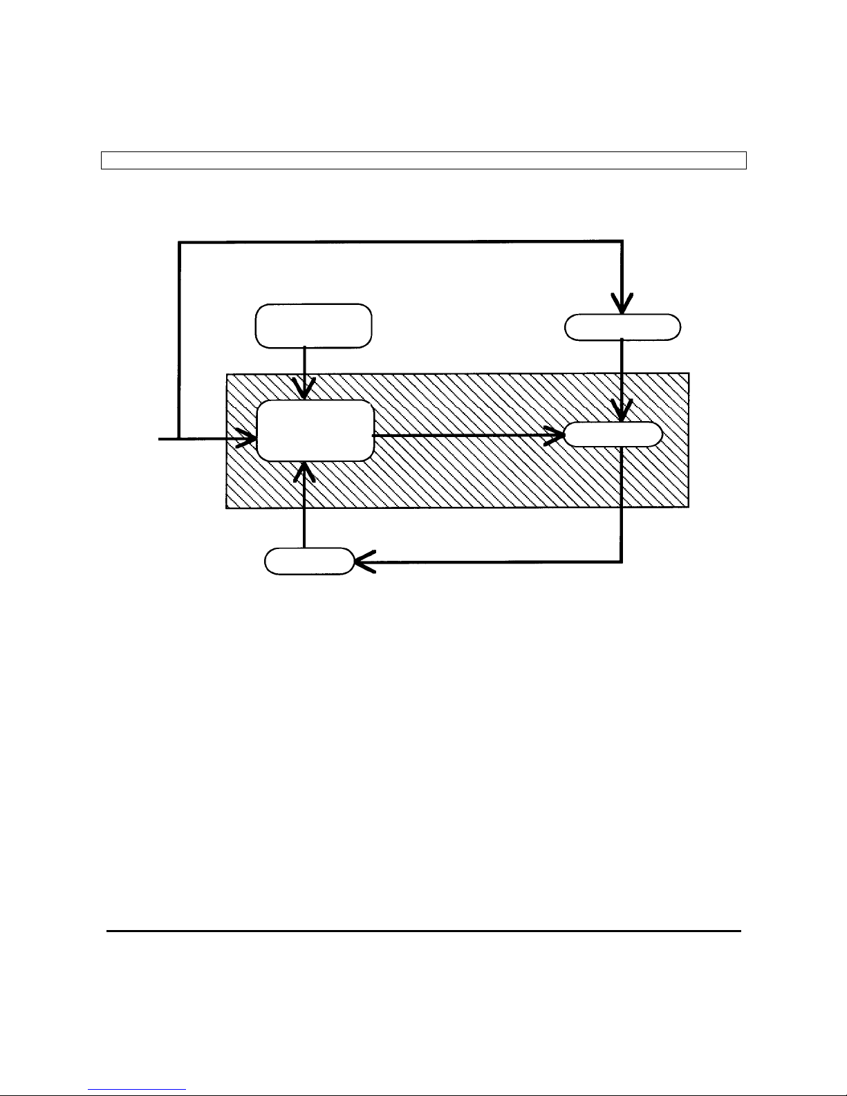
1.2 BLOCK DIAGRAM
MAINS
CONTROL
PANEL
TRANSF.
CONTROL
CIRCUIT
POWER
BAND

THERMOSALD UPSCR_M_V4 – USE AND MAINTENANCE MANUAL - Rev. 2001 / 05
Page N. 7 - Tot. 44
2 WIRING DIAGRAM AND DIMENSIONS
2.1 LIST OF CHANGE-OVER SIGNALS
CN1 POWER
(Power circuit supply synchronised with control circuit supply )
PIN1 ALTERNATING CURRENT SUPPLY (4 - 6 sq.mm)
PIN2 ALTERNATING CURRENT SUPPLY (4 - 6 sq.mm)
PIN3 BAND + (4 - 6 sq.mm)
PIN4 BAND - (4 - 6 sq.mm)
PIN5 EARTH (4 - 6 sq.mm)
CN2 CONTROL CIRCUIT SUPPLY
(Control circuit supply synchronised with power circuit supply )
PIN 1 230 Vac ( 0.1A absorption, max) (1sq.mm)
PIN 2 230 Vac ( 0.1A absorption, max) (1sq.mm)
CN3 CONTROLS
PIN1 COMMON 0 V PLC (0.5 sq.mm)
PIN2 PRE-HEAT SIGNAL FROM PLC, 24V DC ( 12 mA absorption, max) (0.5 sq.mm)
PIN3 SEALING SIGNAL FROM PLC, 24V DC ( 12 mA absorption, max) (0,5 sq.mm)
PIN4 SEALING FAULT (CONTACT N.C.) cosΦ = 1 250V 8A (0,5 sq.mm)
PIN5 SEALING FAULT (CONTACT N.C.) cosΦ = 0.4 250V 5A (0,5 sq.mm)
PIN6 BAND REFERENCE + (0,5 sq.mm)
PIN7 BAND REFERENCE - (0,5 sq.mm)
PIN8 SIGNAL LEAD SCREEN (do not connect from the machine side) (1 sq.mm)
CN4 DISPLAY CONSOLE
PIN1 Supply, +5V Screened (0,25 sq.mm)
PIN2 Supply, 0 V Screened (0,25 sq.mm)
PIN3 Data Screened (0,25 sq.mm)
PIN4 Clock Screened (0,25 sq.mm)
PIN5 Key Screened (0,25 sq.mm)
PIN6 Key Screened (0,25 sq.mm)
PIN7 Key Screened (0,25 sq.mm)
PIN8 Key Screened (0,25 sq.mm)
THERMOSALD UPSCR_M_V4 – USE AND MAINTENANCE MANUAL - Rev. 2001 / 05
Page N. 8 - Tot. 44
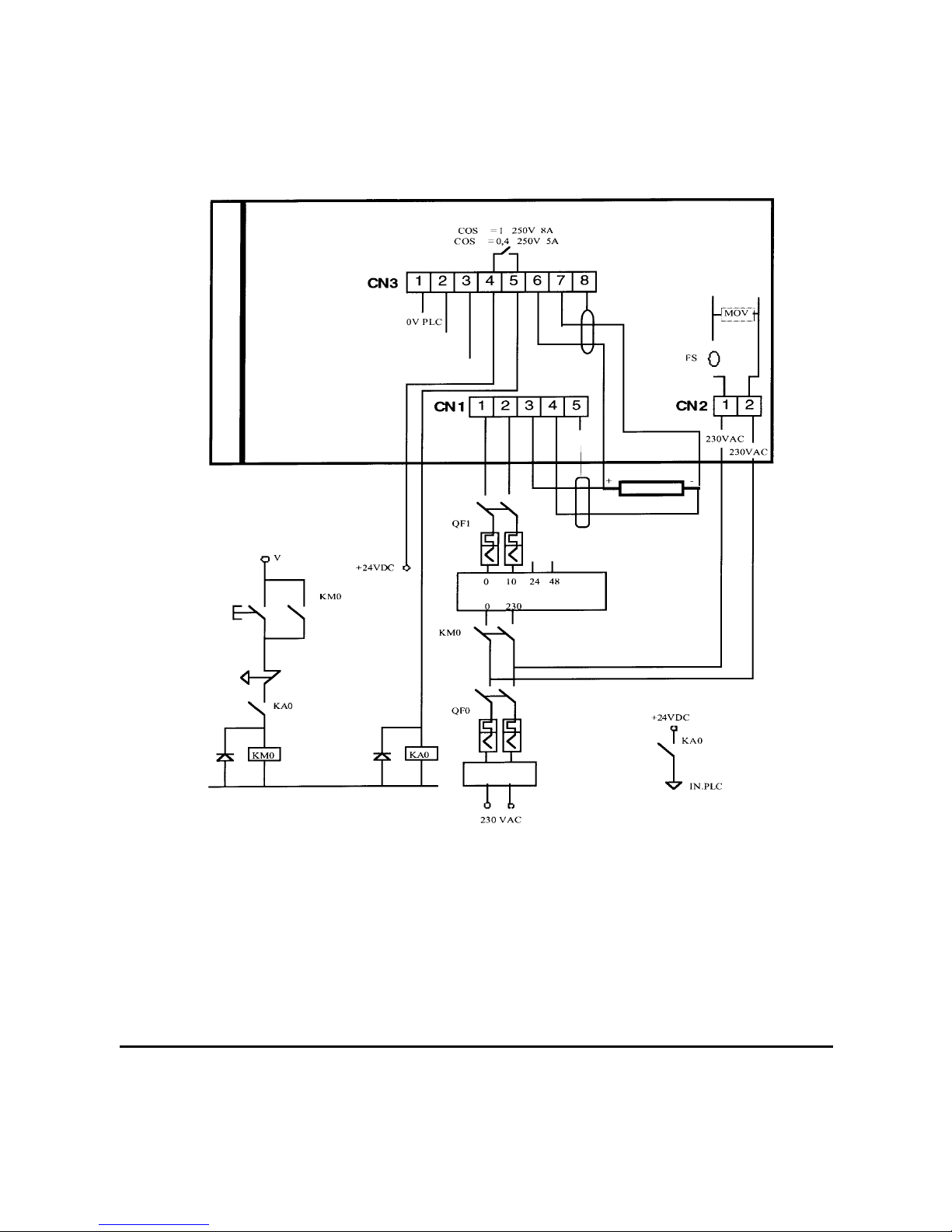
2.2 WIRING DIAGRAM
- NOTE
The power circuit supply ( CN1/1 and CN1/2 ) MUST BE synchronised with the control circuit
supply ( CN2/1 and CN2/2 ).
CN1/5 should be connected to the EARTH ELECTRODE of the machine by using a yellowgreen wire whose size should be >= that of the power leads.
SEALING FAULT
REF.+ REF.-
EARTH
PRE-HEATING SIGNAL (INPUT FROM PLC)
SEALING SIGNAL (INPUT FROM PLC)
EARTH
BAND
TRANSFORMER 1000VA
EMERGENCY
STOP BUTTON
EMC FILTER
board faulty

THERMOSALD UPSCR_M_V4 – USE AND MAINTENANCE MANUAL - Rev. 2001 / 05
Page N. 9 - Tot. 44
2.3 PANEL – BOARD CONNECTING CABLE DIAGRAM
• Use a 8 x 0,22 multi-core screened cable. The screen must be wired to both connectors. It is
advisable to run this cable away from transformer or unscreened power leads.
Canon 9-pin male connector Canon 9-pin female connector
Board side Panel side
1 + 5V ___________________________________________ 1 + 5V
2 0V ___________________________________________ 2 0V
3 Data ___________________________________________ 3 Data
4 Clock ___________________________________________ 4 Clock
5 Key ___________________________________________ 5 Key
6 Key ___________________________________________ 6 Key
7 Key ___________________________________________ 7 Key
8 Key ___________________________________________ 8 Key
GREEN
RED
WHITE
YELLOW
ORANGE
BROWN
BLACK
BLUE

THERMOSALD UPSCR_M_V4 – USE AND MAINTENANCE MANUAL - Rev. 2001 / 05
Page N. 10 - Tot. 44
3 - INSTALLATION
3.1 – ANALYSIS OF APPLICATION
BEFORE BEGINNING THE FIRST INSTALLATION, READ CAREFULLY THE
WARNINGS AT CHAPTER 0 AND PARTICULARLY THE SAFETY PRECUTIONS AT
CHAPTER 0.1 AND COMPLIANCE WITH ELECTRO-MAGNETICS STANDARDS AT
CHAPTER 0.2.
IT IS ENOUGH FOLLOW STEP TO STEP THE FOLLOWING INSTRUCTIONS TO START
UP THERMOREGULATOR WELL; FOR ANY QUESTIONS DON’T EXITATE TO
CONTACT OUR TECHNICAL OFFICE.
• WHICH BAND CAN USE TO HAVE THE MAXIMUM?
If You like You can contact our technical office to choise band
Material:
• Original bands by 3E in special alloy Good
• NiCr80/20 No good
• Altro: Contact our technical office
Profile:
• Chamfered (tapered edge) …………………….
• Flat …………………….
• Concave (grooved) …………………….
• Double …………………….
• Beaded …………………….
• T-Shape …………………….
• Cutting wire …………………….
• Endless steel bands …………………….
• Other …………………….
Geometrical Dimensions:
• Width: LARG= ……………………. [mm]
• Thickness: SP= ……………………. [mm]
• Length : L-TOT= ……………………. [mm]
• Copper/Silver Ends: L-RAM= ……………………. [2 x mm]
• Copper/Silver in the center: L-RAMC= ……………………. [mm]
• Teflon in the center: L-TEFL= ……………………. [mm]
• Other: …………………….

THERMOSALD UPSCR_M_V4 – USE AND MAINTENANCE MANUAL - Rev. 2001 / 05
Page N. 11 - Tot. 44
• CALCULATION OF THE USABLE BAND LENGTH
It’s the length of the part not coppered; it’s calculated by the following formula:
L-UTIL = LTOT – (LRAM x 2) – LRAMC)
Usable length: L-UTIL = ……………………. [mm]
• CALCULATION OF THE BAND SECTION
The band section is calculated by the following formula:
SEZ = LARG x SP in mmq
Section: SEZ = ……………………. [mmq]
3.2 - CALCULATION OF SEALING BAND RESISTANCE
If You USE AN ORIGINAL band 3E included in the underlying tables, You can calculate band resistance using the
tables and applying the following formula:
1 – single band = R-BAND = R0 x L-UTIL [ mt. ]
2 – 2 bands in series = R-BAND = R0 x L-UTIL x 2 [ mt. ]
3 – 2 bands in parallel = R-BAND = R0 x L-UTIL / 2 [ mt. ]
R0 = Specific resistance of the band [ ΩΩΩΩ / mt ]
L – UTIL = Usable length of the band [ mt. ]
If You DON’T USE AN ORIGINAL band 3E included in the underlying tables, You must measure the band resistance
directly on te contact with a precision instrument.
Resistance: R-BAND= ……………………. [ ΩΩΩΩ ]
THERMOSALD UPSCR_M_V4 – USE AND MAINTENANCE MANUAL - Rev. 2001 / 05
Page N. 12 - Tot. 44
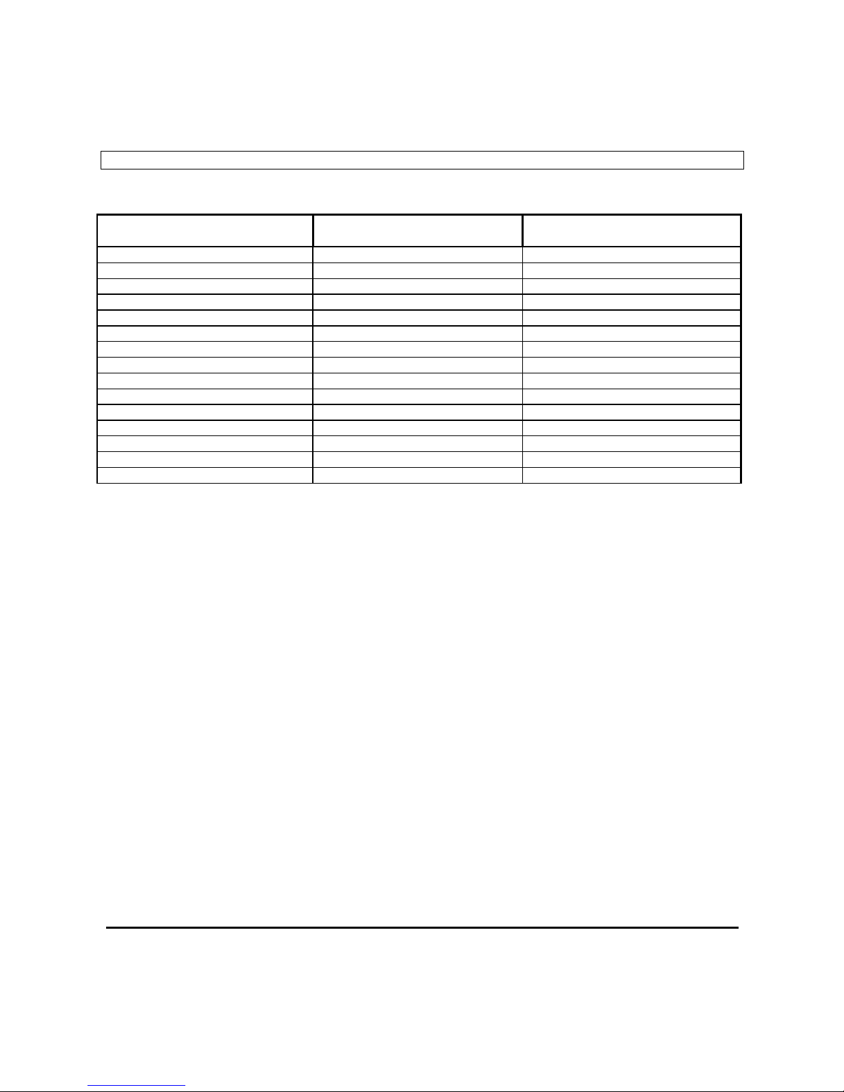
• CHAMFERED SEALING BAND RESISTANCES CHART
Band width
(mm)
Band thickness
(mm)
Specific resistance R0
ΩΩΩΩ / mt
1.5 0.3 1.91
2 0.25 1.58
3 0.1 2.81
3 0.15 1.95
3 0.2 1.50
3 0.25 1.27
4 0.1 2.37
4 0.15 1.40
4 0.2 1.12
4 0.25 0.96
5 0.2 0.8
6 0.1 1.6
6 0.2 0.72
8 0.1 1.2
8 0.2 0.51

THERMOSALD UPSCR_M_V4 – USE AND MAINTENANCE MANUAL - Rev. 2001 / 05
Page N. 13 - Tot. 44
3.3 THERMOSALD CHOISE
• WHAT TYPE OF THERMOREGULATOR YOU NEED TO CHOOSE (30 / 60 / 90 AMPERE?)
The choise depend on the band section and on the connnection in parallel or series.
In the next table, You can see some example of choosing.
For different bands You can calculate about 30 Ampere / mmq.
SECTION MODEL CONFIGURATION PARALLEL ACTIVE I SHORT C.
(SEZ.) (RATED I) MAXIMUM CURRENT
1 30A 4 x 0,25 NO 60 Amp 100 Amp
1 30A 5 x 0,2 NO 60 Amp 100 Amp
1,2 30A 6 x 0,2 NO 60 Amp 100 Amp
1,2 30A 8 x 0,15 NO 60 Amp 100 Amp
SECTION MODEL CONFIGURATION PARALLEL ACTIVE I SHORT C.
(SEZ.) (RATED I) MAXIMUM CURRENT
2 60A 4 x 0,25 x 2 SI 120 Amp 140 Amp
2 60A 5 x 0,2 x 2 SI 120 Amp 140 Amp
2,4 60A 6 x 0,2 x 2 SI 120 Amp 140 Amp
2,4 60A 8 x 0,15 x 2 SI 120 Amp 140 Amp
SECTION MODEL CONFIGURATION PARALLEL ACTIVE I SHORT C.
(SEZ.) (RATED I) MAXIMUM CURRENT
3,2 90A 8 x 0,2 x 2 SI 180 Amp 210 Amp
Thermoregulator model: UPSCR_M_V4_100……. [ 30/60/90 Ampere ]

THERMOSALD UPSCR_M_V4 – USE AND MAINTENANCE MANUAL - Rev. 2001 / 05
Page N. 14 - Tot. 44
3.4 - POWER TRANSFORMER CHOISE
• WHAT TYPE OF TRANSFORMER YOU MUST CHOOSE?
The choise depend on the rated current oh the thermoregulator choosed.
For the first start up, we recommend to use the original multi-voltage power transformers by 3E, specific for the
thermoregolators 30 / 60 / 90 Ampere.
For the following start up we can supply original single voltage power transformers by 3E, specific for the thermoregolators
30 / 60 / 90 Ampere.
If You prefer to use a different transformer from above refer to technical characteristic on this book, see ANNEX F –
MULTIVLTAGE TRANSFORMER TECHNICAL FEATURES.
• WHICH VOLTAGE ON THE SECONDARY OF POWER TRASFORMER YOU MUST CHOOSE?
The choise depend on the rated current of thermoregulator (30/60/90) and on the resistance of the bands R-BAND
Calculations:
(V SECONDARY lowest = R-BAND x I rated
V SECONDARY OPTIMUM = R-BAND x I rated x 1.5
V SECONDARY highest = R-BAND x I rated x 2
- Example:
If you must connect a band of resistance 0.4 Ohm, with a thermoregulator 60 Ampere, the V SECONDARY OPTIMUM
VOLTAGE will be 0.4 Ohm x 60 Ampere x 1.5 = 36 Volts a.c..
Trasformer: POWER = ……………………. [ VA ]
PRIMARY = ……………………. [ V ]
SECONDARY = ……………………. [ V ]
 Loading...