

THERMOSALD UPSCR10030-M-V3, UPSCR10060-M-V3, UPSCR10045-M-V3, UPSCR10090-M-V3 Maintenance & Operation Manual

THERMOSALD
UPSCR10030-M-V3
UPSCR10045-M-V3
UPSCR10060-M-V3
UPSCR10090-M-V3
(08/2000)
TEMPERATURE CONTROLLER
for
IMPULSE HEAT-SEALING
(automatic calibrating system)
MAINTENANCE & OPERATIONS MANUAL
HARDWARE MOD. M
SOFTWARE V. 3
3E S.r.l.
-
Via del Maccabreccia 37/a - 40012 LIPPO DI CALDERARA ( BOLOGNA )
Tel. ++39 051 6466225 Fax ++39 051 6426252
e-Mail : mail@3e3e Website : http://www.3e3e3e.com

Pag. 2 Tot 27.
THERMOSALD UPSCR_M_V3
08/2000
0 WARNINGS
0.1 SAFETY PRECAUTIONS
- Never use the equipment in explosive atmospheres or with explosive materials.
- Never use the equipment with flammable material without first taking the
required safety precautions.
- Never turn on the temperature controller power circuit when the safety guards are
open.
- Do not use the temperature controller for tasks other than those it is designed for
i.e to control the temperature of bands or wires for industrial-grade sealing.
Contact our engineering department for information regarding specific
applications.
- Do not deliver electrical power to the temperature controller if the protective
cover has been removed for special servicing on the electronic system.
- Operate the equipment by following the instructions contained herein.
- Employ qualified and well-trained personnel, familiar with the technology used
to install the equipment and put it into service.
- Use bands or wires having an adequate positive temperature coefficient ( > 1 x
10E-3)
- When the machine is running under normal conditions, make sure the heat sink of
the controller does not exceed 60°C . If this happens, increase heat sink
ventilation or contact our engineering department.

Pag. 3 Tot 27.
THERMOSALD UPSCR_M_V3
08/2000
0.2 COMPLIANCE WITH ELECRO-MAGNETIC STANDARDS - CE KITE MARKS
Directives which apply :
• Low voltage electrical codes : 73/23 CEE - 9368 CEE (in force since 01/01/97)
• Elecro-magnetic compatibility : 89/336 CEE - 92/31 CEE - 93/68 CEE ( in force since 01/01/96 )
• Machine directive : 89/392 CEE - 91/368 CEE - 93/68 CEE ( in force since 01/01/95 )
NOTE - this directive does not automatically apply to the elecronic equipment; our controllers are designed to conform
with the directive if installed correctly as described in this user's manual.
Electro-magnetic compliance tests :
Test conditions :
•••• Mains supply filter Mod. Siemens B84112-B-B60 ( 115 / 250 V - 6A - 50/60 Hz )
•••• Temperature controller connecting cable and standard panel 3ESD0035E ( 5 m )
•••• Input power cables (3 m long)
• Band output cables (10 m long)
Safety tests :
•••• The criteria indicated in the EN50082-2 directive have been followed: general standards regarding safety in industry.
•••• IEC 1000-4-2 ( IEC 801-2/1991): STATIC ELECTRICITY DISCHARGE ( ESD )
•••• IEC 1000-4-3 ( CEI 801-3 ): RADIATED ELECTRO-MAGNETIC FIELD
•••• IEC 1000-4-4 ( CEI 801-4 ): FAST TRANSIENT OSCILLATIONS ( FAST TRANSIENT / BURST )
•••• ENV50141: MAINS PICKUP INTERFERENCE
Emissions tests :
•••• The criteria specified in the EN50081 -2 directive have been followed: general rules regarding emissions in industry
•••• EN55011 ( CEI 110-6 ): LIMITS AND METHODS OF MEASURING RADIO INTERFERENCE PRODUCED BY
INDUSTRIAL, SCIENTIFIC AND MEDICAL EQUIPMENT ( ISM )
Compliance certificate :
•••• The temperature controller passed the compliance tests and is considered a class B device.
•••• The manufacturer states that the temperature controller fully complies with current council directives as regards electro-
magnetic compatibility, 89/336 CEE standards and following amendments
• The manufacturer states that the temperature controller fully complies with current low voltage electrical codes 73/23
CEE and subsequent amendments.

Pag. 4 Tot 27.
THERMOSALD UPSCR_M_V3
08/2000
CONTENTS
0 WARNINGS
0.1 SAFETY PRECAUTIONS
0.2 COMPLIANCE WITH ELECRO-MAGNETIC STANDARDS
1 DESCRIPTION
1.1 GENERAL DESCRIPTION
1.2 BLOCK DIAGRAM
2 WIRING DIAGRAM AND DIMENSIONS
2.1 LIST OF CHANGE-OVER SIGNALS
2.2 WIRING DIAGRAM
2.3 PANEL - BOARD CONNECTING CABLE DIAGRAM
2.4 POWER TRANSFORMER DIMENSIONS
2.5 PROTECTIVE DEVICE DIMENSIONS
2.6 BAND RESISTANCE CHART
3 COMMISSIONING
3.1 FIRST TIME START-UP
3.2 GENERAL COMMISSIONING
3.3 AUTOMATIC CALIBRATION
3.4 ENERGY CONTROL ENABLING
3.5 SETTING THE PRE-HEATING AND SEALING TEMPERATURES
3.6 CURRENT/TEMPERATURE DISPLAY
3.7 COLD SYSTEM COMPENSATION OPTION
3.8 GENERAL RESET PROCEDURE
4 MACHINE DATA
5 LIST OF FAULT MESSAGES ( CAUSES - REMEDIES )
6 DIMENSIONS
6.1 TEMPERATURE CONTROLLER DIMENSIONS
6.2 PANEL DIMENSIONS
7 SPECIFICATIONS
8 DETAILS FOR ORDER FORM
Annex A SEALING CYCLE
Annex B INSTALLING THE TEMPERATURE CONTROLLER
Annex C TROUBLE-SHOOTING
Annex D CARD REQUIRED TO PUT THE MACHINE INTO OPERATION
Pag. 5 Tot 27.
THERMOSALD UPSCR_M_V3
08/2000
1 DESCRIPTION
1.1 GENERAL DESCRIPTION
• APPLICATION: Impulse heat sealers are used to seal polyethylene film, single-component plastic material or plastic
material in general rapidly and with great accuracy. These materials should reach their melting temperature and cool
down immediately in order to avoid deformation.
• OPERATING PRINCIPLES: To impulse-seal the plastic material, use a sealing bar with bands or wires supplied by a
piece of electronic equipment designed specifically for this application and capable of delivering the power required to
maintain the band at the desired temperature during the sealing operations. No additional probes are required, the
equipment simply reads the feedback signals from the bands and controls the heating current with a closed-loop circuit.
The temperature controller first receives a pre-heat signal from the outside so that the sealing bars can reach the
required temperature before starting work . A further signal is emitted to allow the correct temperature to be attained
when the sealing bars are brought together.
• MAIN FEATURES: The temperature controller allows the user to check the band characteristics and the state of the
machine and to locate faults by referring to the display console. The system is provided with an "automatic
calibration" function so that the band can be set up simply by pressing a key.
• DIAGNOSTICS: The temperature controller comes with an efficient diagnostics system capable of identifying faults
which have occured during the production process, indicating the cause and suggesting the remedies required to restore
normal operating conditions.
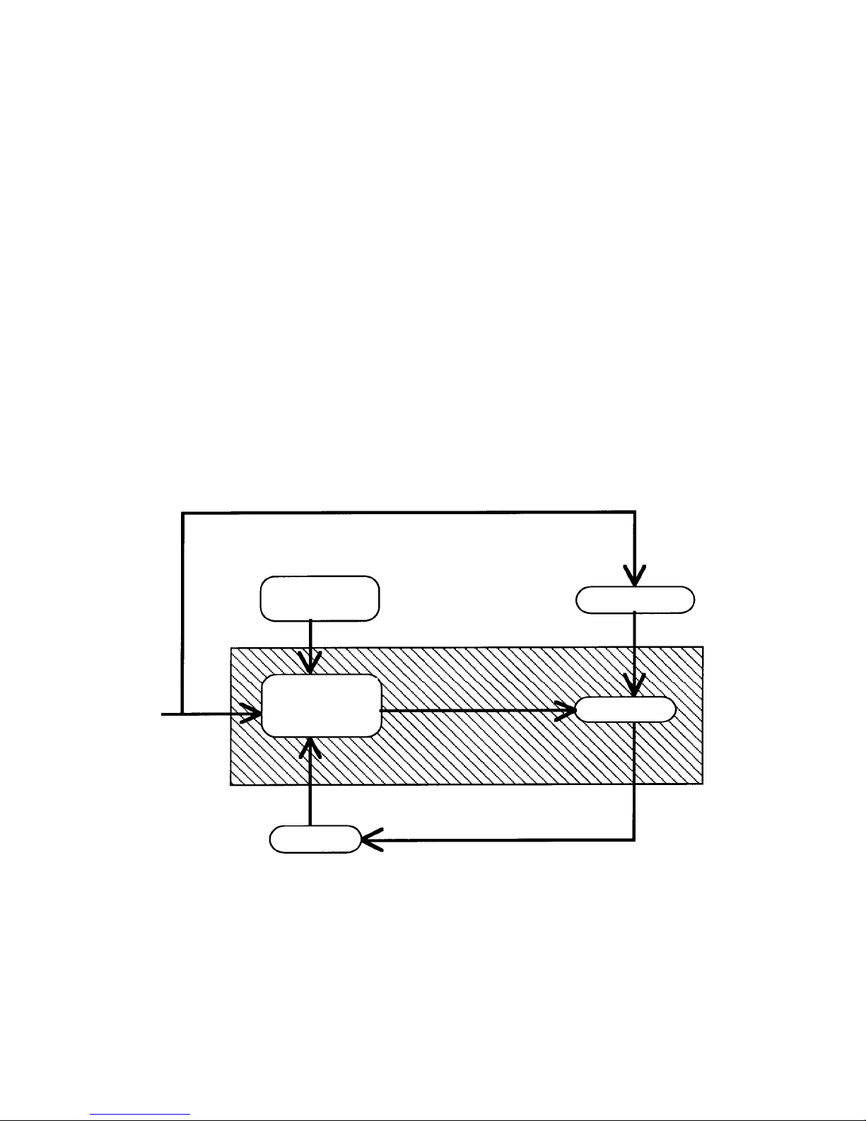
1.2 BLOCK DIAGRAM
MAINS
CONTROL
PANEL
TRANSF.
CONTROL
CIRCUIT
POWER
BAND

Pag. 6 Tot 27.
THERMOSALD UPSCR_M_V3
08/2000
2 WIRING DIAGRAM
2.1 LIST OF CHANGE-OVER SIGNALS
CN1 POWER
(Power circuit supply synchronised with control circuit supply )
PIN1 ALTERNATING CURRENT SUPPLY (4 - 6 sq.mm)
PIN2 ALTERNATING CURRENT SUPPLY (4 - 6 sq.mm)
PIN3 BAND + (4 - 6 sq.mm)
PIN4 BAND - (4 - 6 sq.mm)
PIN5 EARTH (4 - 6 sq.mm)
CN2 CONTROL CIRCUIT SUPPLY
(Control circuit supply synchronised with power circuit supply )
PIN 1 230 Vac ( 0.1A absorption, max) (1sq.mm)
PIN 2 230 Vac ( 0.1A absorption, max) (1sq.mm)
CN3 CONTROLS
PIN1 COMMON 0 V PLC (0.5 sq.mm)
PIN2 PRE-HEAT SIGNAL FROM PLC, 24V DC ( 12 mA absorption, max) (0.5 sq.mm)
PIN3 SEALING SIGNAL FROM PLC, 24V DC ( 12 mA absorption, max) (0,5 sq.mm)
PIN4 SEALING FAULT (CONTACT N.C.) cosΦ = 1 250V 8A (0,5 sq.mm)
PIN5 SEALING FAULT (CONTACT N.C.) cosΦ = 0.4 250V 5A (0,5 sq.mm)
PIN6 BAND REFERENCE + (0,5 sq.mm)
PIN7 BAND REFERENCE - (0,5 sq.mm)
PIN8 SIGNAL LEAD SCREEN (do not connect from the machine side) (1 sq.mm)
CN4 DISPLAY CONSOLE
PIN1 Supply, +5V Screened (0,25 sq.mm)
PIN2 Supply, 0 V Screened (0,25 sq.mm)
PIN3 Data Screened (0,25 sq.mm)
PIN4 Clock Screened (0,25 sq.mm)
PIN5 Key Screened (0,25 sq.mm)
PIN6 Key Screened (0,25 sq.mm)
PIN7 Key Screened (0,25 sq.mm)
PIN8 Key Screened (0,25 sq.mm)
Pag. 7 Tot 27.
THERMOSALD UPSCR_M_V3
08/2000
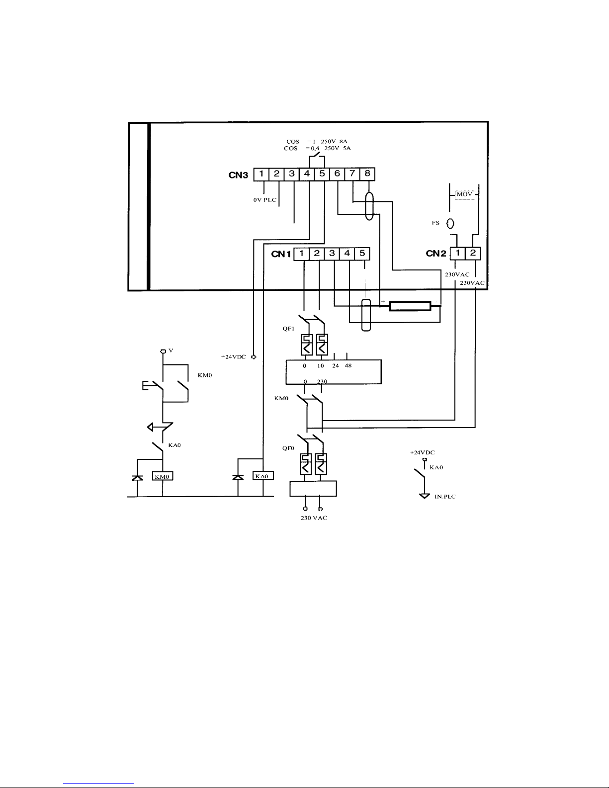
2.2 WIRING DIAGRAM
- NOTE
The power circuit supply ( CN1/1 and CN1/2 ) MUST BE synchronised with the control
circuit supply ( CN2/1 and CN2/2 ).
CN1/5 should be connected to the EARTH ELECTRODE of the machine by using a
yellow-green wire whose size should be >= that of the power leads.
SEALING FAULT
REF.+ REF.-
EARTH
PRE-HEATING SIGNAL (INPUT FROM PLC)
SEALING SIGNAL (INPUT FROM PLC)
EARTH
BAND
TRANSFORMER 1000VA
EMERGENCY
STOP BUTTON
EMC FILTER
board faulty

Pag. 8 Tot 27.
THERMOSALD UPSCR_M_V3
08/2000
2.3 BOARD-PANEL CONNECTING CABLE DIAGRAM
Board side Panel side
Canon 9-pin male connector Canon 9-pin female connector
1 + 5V ___________________________________________ 1 + 5V
2 0V ___________________________________________ 2 0V
3 Data ___________________________________________ 3 Data
4 Clock ___________________________________________ 4 Clock
5 Key ___________________________________________ 5 Key
6 Key ___________________________________________ 6 Key
7 Key ___________________________________________ 7 Key
8 Key ___________________________________________ 8 Key
2.4 POWER TRANSFORMER DIMENSIONS
2.5 PROTECTIVE DEVICE DIMENSIONS
• Use a 8 x 0.22 multi-core screened cable. The screen must be wired to both connectors. It is advisable to run this cable
away from transformers or unscreened power leads.
PRIMARY WINDING: 0/230/400 Vac
(With a 400 Vac primary winding, use a 230 Vac autotransformer
or a 400/230 external transformer to supply the synchronised logic system)
CORE: EARTHED
SECONDARY WINDING: DETERMINED BY USING THE FOLLOWING FORMULA :
TRANSFORMER RATED V = R x RATED I
( RATED I = 30 AMP. FOR TEMPERATURE CONTROLLER UPSCR10030, UPSCR10045
RATED I = 60 AMP. FOR TEMPERATURE CONTROLLER UPSCR10060, UPSCR10090
BAND RESISTANCE R = DETERMINED BY TAKING DIRECT READINGS AT THE ENDS OF THE BAND (OR
CALCULATED BY REFERRING TO THE CHART IN THE BLOCK BELOW, CHAPTER 2.6)
SUPERIMPOSED WINDINGS
ELECTRICAL SPECIFICATIONS:
THE VOLTAGE IN THE SECONDARY WINDING CAN BE STEPPED UP 1.6 TIMES (MAX.) IN ORDER TO
INCREASE THE SEALING SPEED.
GREEN
RED
WHITE
YELLOW
ORANGE
BROWN
BLACK
BLUE
Pag. 9 Tot 27.
THERMOSALD UPSCR_M_V3
08/2000
REFER TO CHAP. 3.4 - WIRING DIAGRAM
CN2 - 230 V SUPPLY : INTERNAL PROTECTION DEVICE PROVIDED
QF0 - D-TYPE, TWO-POLE CIRCUIT BREAKER OR DELAYED-ACTION FUSE
( 6A 1000 VA TRANSFORMER / 8A 1400 VA TRANSFORMER)
QF1 - C-TYPE, TWO-POLE CIRCUIT BREAKER OR FUSE
( 40A WITH BOARD 10030 SCR uP : RATED I = 30A )
( 63A WITH BOARD 10060 SCR uP :RATED I = 60A )
The recommended specifications are for indication purposes only. Take into consideration the electrical system being used
when examining these specifications.
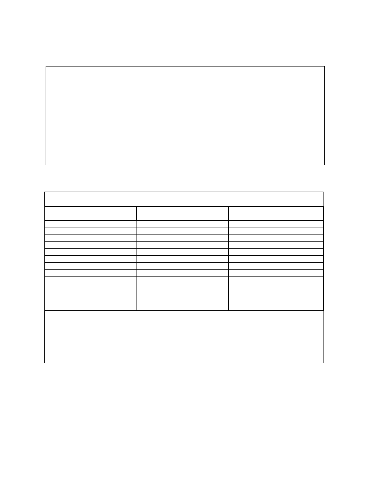
2.6 BAND RESISTANCE CHART
3 COMMISSIONING
Band length
BEVELLED
Band thickness
BEVELLED
Specific resistance R0
ΩΩΩΩ / m
3 0.1 2.81
3 0.15 1.95
3 0.2 1.50
3 0.25 1.27
4 0.1 2.37
4 0.15 1.40
4 0.2 1.12
4 0.25 0.96
5 0.2 0.8
6 0.1 1.6
6 0.2 0.72
8 0.1 1.2
8 0.2 0.51
Determining the resistance of the band on the machine ( R )
1 - Single band : R = R0 x band length [ m ]
2 - 2 series-connected bands : R = R0 x band length [ m ] x 2
3 - 2 parallel-connected bands : R = R0 x band length [ m ] / 2
NOTE : With copper-coated bands, "band length" refers to the portion which is not copper-coated
 Loading...