

Page 1

TriPlus RSH
Robotic Sample Handling
Hardware Manual
P/N 31709640 Ninth Edition December 2015
Page 2

© 2015 Thermo Fisher Scientific Inc. All rights reserved.
TriPlus RSH, TRACE 1300, TRACE 1310, TRACE GC Ultra, and FOCUS GC are trademarks of Thermo
Fisher Scientific Inc., and its subsidiaries.
Published by Thermo Fisher Scientific S.p.A., Strada Rivoltana 20090 Rodano-Milan, Italy
Tel: +39 02 95059303; Fax: +39 02 95059388
Thermo Fisher Scientific Inc. provides this document to its customers with a product purchase to use in the
product operation. This document is copyright protected and any reproduction of the whole or any part of this
document is strictly prohibited, except with the written authorization of Thermo Fisher Scientific Inc.
The contents of this document are subject to change without notice. All technical information in this
document is for reference purposes only. System configurations and specifications in this document supersede
all previous information received by the purchaser.
Thermo Fisher Scientific Inc. makes no representations that this document is complete, accurate or errorfree and assumes no responsibility and will not be liable for any errors, omissions, damage or loss that might
result from any use of this document, even if the information in the document is followed properly.
This document is not part of any sales contract between Thermo Fisher Scientific Inc. and a purchaser. This
document shall in no way govern or modify any Terms and Conditions of Sale, which Terms and Conditions of
Sale shall govern all conflicting information between the two documents.
Release history:
First edition, released September 2011 “Original Instructions”
Second edition, October 2011; Third edition, March 2012; Fourth edition, September 2012; Fifth edition,
March 2013; Sixth edition, October 2013; Seventh edition, June 2014; Eighth Edition, February 2015; Ninth
Edition, December 2015
For Research Use Only. Not for use in diagnostic procedures.
Page 3

TriPlus RSH Hardware Manual, PN 31709640, Ninth Edition
Reader’s Survey
fold
fold
Strongly
Agree
Agree Neutral Disagree
Strongly
Disagree
The manual is well organized. 1 2 3 4 5
The manual is clearly written. 1 2 3 4 5
The manual contains all the info rmation I need. 1 2 3 4 5
The instructions are easy to follow. 1 2 3 4 5
The instructions are complete. 1 2 3 4 5
The technical information is easy to understand. 1 2 3 4 5
Examples of operation are clear and useful. 1 2 3 4 5
The figures are helpful. 1 2 3 4 5
I was able to operate the system using this manual. 1 2 3 4 5
If not, please comment below. Attach additional sheets if necessary.
__________________________________________________________ __________________________________________________________________
__________________________________________________________ __________________________________________________________________
__________________________________________________________ __________________________________________________________________
__________________________________________________________ __________________________________________________________________
__________________________________________________________ __________________________________________________________________
__________________________________________________________ __________________________________________________________________
__________________________________________________________ __________________________________________________________________
__________________________________________________________ __________________________________________________________________
__________________________________________________________ __________________________________________________________________
Customer Registration Card
Register now…and receive all the privileges associated with being a Thermo Fisher Scientific product user including customer
support, application reports, and technical reports.
MY ORGANIZATION IS: (Check only one) MY PRIMARY APPLICATION IS: (Check only one)
❏ Commercial (for profit) lab ❏ Analytical
❏ Government lab ❏ Biomedical
❏ Hospital/Clinic ❏ Clinical/Toxicology
❏ Industrial lab ❏ Energy
❏ Research Institute ❏ Environmental
❏ University/College ❏ Food/Agricultural
❏ Veterinary ❏ Forensic/Toxicology
❏ Other______________________ ❏ Pharmaceutical
❏ Research/Education
MY PRIMARY JOB FUNCTION IS: (Check only one)
❏ Administration
❏ Lab management
❏ Operator
❏ Other______________________
❏ Other______________________
Name __________________________________________________Title__________________________________________________________________
Company __________________________________________________ __________________________________________________________________
Address ___________________________________________________ __________________________________________________________________
City/State _________________ ___________________ _____Postal Code____________________ ______________________________________________
Country ___________________________________________________ __________________________________________________________________
Telephone_______________________________________________ Ext. __________________________________________________________________
Serial Number __________________________________ Date purchased __________________________________________________________________
Fold and mail or e-mail to:
Editor, Technical Publications
Thermo Fisher Scientific S.p.A.
Strada Rivoltana km 4
20090 Rodano (MI)
Italy
Editor, Technical Publications
Thermo Fisher Scientific SID GC-GC/MS
2215 Grand Avenue Parkway
Austin TX 78728-3812
Unites States of America
Page 4

Page 5

Declaration
Manufacturer: Thermo Fisher Scientific
Thermo Fisher Scientific is the manufacturer of the instrument described in this manual and, as such, is responsible
for the instrument safety, reliability and performance only if:
•installation
•re-calibration
•changes and repairs
have been carried out by authorized personnel and if:
• the local installation complies with local law regulations
• the instrument is used according to the instructions provided and if its operation is only entrusted to qualified
trained personnel
Thermo Fisher Scientific is not liable for any damages derived from the non-compliance with the aforementioned
recommendations.
Thermo Fisher Scientific S.p.A.
Strada Rivoltana, 20090 Rodano - Milan - Italy — Tel: +39 02 950591 - Fax: +39 02 9505276
Regulatory Compliance
Thermo Fisher Scientific performs complete testing and evaluation of its products to ensure full compliance with
applicable domestic and international regulations.
Thermo Fisher Scientific declares, under sole responsibility, that the product as originally delivered complies with
the requirements of the following applicable European Directives and carries the CE marking accordingly:
• Low Voltage Directive:2006/95/EC
• EMC Directive:2004/108/EC
• Machinery Directive: 2006/42/EC
… and conforms with the following product standards:
Safety
This device complies with:
• IEC61010-1:2010 3rd Edition | IEC/EN 61010-1 3rd Edition
• ANSI/UL 61010-1:2004 2nd Edition | CAN/CSA C22.2 No. 61010-1:2004 2nd Edition.
• EN 61010-2-010:2003 | EN 61010-2-051:2003 | EN 61010-2-081:2001+A1:2003 | EN 61010-2 101:2003
Electromagnetic Compatibility
This device complies with:
• IEC 61326-1:2nd Edition | EN 61326-1:2013 | CISPR 11:5th Edition
• EN 61000-6-2:2005 | IEC 61000-6-2:2nd Edition| IEC 61000-6-3:2nd Edition am1 | EN 61000-6-3:2007 +
A1:2011
• Conducted Emission, Subpart B. FCC part 15, §15.107(a) and §15.109(a)
Laser Class 1
The selected Class 1 Laser for the TriPlus RSH module Barcode Reader complies with the following regulations:
Page 6

• 21 CFR1040.10 and 1040.11 except for deviations pursuant to Laser Notice No. 50, dated July 26, 2001
• EN60825-1:1994 + A1:2002 + A2:2001
• IEC60825-1:1993 + A1:1997 + A2:2001
FCC Compliance Statement
THIS DEVICE COMPLIES WITH PART 15 OF THE FCC RULES. OPERATION IS SUBJECT TO THE
FOLLOWING TWO CONDITIONS: (1) THIS DEVICE MAY NOT CAUSE HARMFUL
INTERFERENCE, AND (2) THIS DEVICE MUST ACCEPT ANY INTERFERENCE RECEIVED,
INCLUDING INTERFERENCE THAT MAY CAUSE UNDESIRED OPERATION.
CAUTION Read and understand the various precautionary notes, signs, and symbols contained
inside this manual pertaining to the safe use and operation of this product before using the device.
Notice on Lifting and Handling of
Thermo Scientific Instruments
For your safety, and in compliance with international regulations, the physical handling of this Thermo Fisher
Scientific instrument requires a team effort to lift and/or move the instrument. This instrument is too heavy and/
or bulky for one person alone to handle safely.
Notice on the Proper Use of
Thermo Scientific Instruments
In compliance with international regulations: Use of this instrument in a manner not specified by Thermo Fisher
Scientific could impair any protection provided by the instrument.
Notice on the Susceptibility
to Electromagnetic Transmissions
Do not use radio frequency transmitters, such as mobile phones, in close proximity to the instrument.
Page 7
WEEE Compliance
This product is required to comply with the European Union’s Waste Electrical & Electronic Equipment (WEEE) Directive
2012/19/EU. It is marked with the following symbol:
Thermo Fisher Scientific has contracted with one or more recycling or disposal companies in each European Union (EU)
Member State, and these companies should dispose of or recycle this product. See www.thermoscientific.com/rohsweee
further information on Thermo Fisher Scientific’s compliance with these Directives and the recyclers in your country.
for
WEEE Konformität
Dieses Produkt muss die EU Waste Electrical & Electronic Equipment (WEEE) Richtlinie 2012/19/EU erfüllen. Das Produkt
ist durch folgendes Symbol gekennzeichnet:
Thermo Fisher Scientific hat Vereinbarungen mit Verwertungs-/Entsorgungsfirmen in allen EU-Mitgliedsstaaten getroffen,
damit dieses Produkt durch diese Firmen wiederverwertet oder entsorgt werden kann. Mehr Information über die Einhaltung
dieser Anweisungen durch Thermo Fisher Scientific, über die Verwerter, und weitere Hinweise, die nützlich sind, um die
Produkte zu identifizieren, die unter diese RoHS Anweisung fallen, finden sie unter www.thermoscientific.com/rohsweee
.
Conformité DEEE
Ce produit doit être conforme à la directive européenne (2012/19/EU) des Déchets d'Equipements Electriques et
Electroniques (DEEE). Il est marqué par le symbole suivant:
Thermo Fisher Scientific s'est associé avec une ou plusieurs compagnies de recyclage dans chaque état membre de l’union
européenne et ce produit devrait être collecté ou recyclé par celles-ci. Davantage d'informations sur la conformité de Thermo
Fisher Scientific à ces directives, les recycleurs dans votre pays et les informations sur les produits Thermo Fisher Scientific qui
peuvent aider la détection des substances sujettes à la directive RoHS sont disponibles sur www.thermoscientific.com/rohsweee
.
Page 8

Conformità RAEE
Questo prodotto è marcato con il seguente simbolo in conformità alla direttiva europea 2012/19/EU (RAEE) sui rifiuti di
apparecchiature elettriche ed elettroniche:
Thermo Fisher Scientific si è accordata con una o più società di riciclaggio in ciascun Stato Membro della Unione Europea
(EU), e queste società dovranno smaltire o riciclare questo prodotto. Per maggiori informazioni vedere il sito
www.thermoscientific.com/rohsweee
.
Conformidad RAEE
Este producto es marcado con el siguiente símbolo en conformidad a la Directiva 2012/19/EU de la Unión Europea sobre los
residuos de aparatos eléctricos y electrónicos:
Thermo Fisher Scientific ha contratado una o más empresas de reciclo para tratar residuos en cada Estado Miembro de la
Unión Europea, y estas empresas deberían reciclar o eliminar este producto. Referirse a www.thermoscientific.com/rohsweee
para una mayor información sobre la conformidad de Thermo Fisher Scientific con estas Directivas y para las empresas de
reciclaje en su país.
IMPORTANT
The symbol indicates the product must not be disposed of with the normal household wastes. Correct disposal of
this product prevents any potentially negative impact on the environmental and human health that could arise
from any inappropriate handling of the product itself.
WEEE and RoHS rules, while laid down at European level, are put into national law at national level. When exporting to Europe, it is essential to comply with national law in each relevant country. The EU law simply serves
as a template for national laws, which may differ considerably.
Each EU Member State has own regulations regarding the application of these directives. Please refer to the
regulations in force in your country.
Page 9

C
Contents
Preface . . . . . . . . . . . . . . . . . . . . . . . . . . . . . . . . . . . . . . . . . . . . . . . . . . . . . . . . . . . . . xiii
About Your System. . . . . . . . . . . . . . . . . . . . . . . . . . . . . . . . . . . . . . . . . . . . . .xiv
Power Rating . . . . . . . . . . . . . . . . . . . . . . . . . . . . . . . . . . . . . . . . . . . . . . . . . .xiv
Contacting Us . . . . . . . . . . . . . . . . . . . . . . . . . . . . . . . . . . . . . . . . . . . . . . . . .xiv
Related Documentation . . . . . . . . . . . . . . . . . . . . . . . . . . . . . . . . . . . . . . . . . . xiv
Safety Alerts and Important Information . . . . . . . . . . . . . . . . . . . . . . . . . . . . . xv
Special Notices . . . . . . . . . . . . . . . . . . . . . . . . . . . . . . . . . . . . . . . . . . . . . . . xv
Safety Symbols and Signal Words . . . . . . . . . . . . . . . . . . . . . . . . . . . . . . . . . xv
Instrument Markings and Symbols . . . . . . . . . . . . . . . . . . . . . . . . . . . . . . . . . xvii
Safety Information and Warnings. . . . . . . . . . . . . . . . . . . . . . . . . . . . . . . . . .xviii
General Considerations . . . . . . . . . . . . . . . . . . . . . . . . . . . . . . . . . . . . . . . .xviii
Electrical Hazards . . . . . . . . . . . . . . . . . . . . . . . . . . . . . . . . . . . . . . . . . . . . xviii
Laser Safety Information . . . . . . . . . . . . . . . . . . . . . . . . . . . . . . . . . . . . . . . . xx
Other Hazards. . . . . . . . . . . . . . . . . . . . . . . . . . . . . . . . . . . . . . . . . . . . . . . .xxi
Working with Toxic or other Harmful Compounds . . . . . . . . . . . . . . . . . . xxii
Biological Hazards. . . . . . . . . . . . . . . . . . . . . . . . . . . . . . . . . . . . . . . . . . . .xxiii
Maintenance . . . . . . . . . . . . . . . . . . . . . . . . . . . . . . . . . . . . . . . . . . . . . . . .xxiii
Disposal. . . . . . . . . . . . . . . . . . . . . . . . . . . . . . . . . . . . . . . . . . . . . . . . . . . .xxiv
Chapter 1 Specifications . . . . . . . . . . . . . . . . . . . . . . . . . . . . . . . . . . . . . . . . . . . . . . . . . . . . . . . . .1
Electrical Specifications . . . . . . . . . . . . . . . . . . . . . . . . . . . . . . . . . . . . . . . . . . . . 2
Physical Specifications . . . . . . . . . . . . . . . . . . . . . . . . . . . . . . . . . . . . . . . . . . . . . 3
Operating and Environmental Specifications. . . . . . . . . . . . . . . . . . . . . . . . . . . . 3
Sound Pressure Level. . . . . . . . . . . . . . . . . . . . . . . . . . . . . . . . . . . . . . . . . . . . . . 4
Hardware and Software Requirements. . . . . . . . . . . . . . . . . . . . . . . . . . . . . . . . . 4
TriPlus RSH System Software Requirements. . . . . . . . . . . . . . . . . . . . . . . . . . . . 7
Chapter 2 Installation of the TriPlus RSH System . . . . . . . . . . . . . . . . . . . . . . . . . . . . . . . . . . . .9
Introduction . . . . . . . . . . . . . . . . . . . . . . . . . . . . . . . . . . . . . . . . . . . . . . . . . . . 10
Installation Quick Reference Guide. . . . . . . . . . . . . . . . . . . . . . . . . . . . . . . . . . 11
Unpacking the Components . . . . . . . . . . . . . . . . . . . . . . . . . . . . . . . . . . . . . . . 12
Installing the TriPlus RSH Supports on the GC . . . . . . . . . . . . . . . . . . . . . . . . 13
Placing the TriPlus RSH on the Supports . . . . . . . . . . . . . . . . . . . . . . . . . . . . . 19
Installation of the TriPlus RSH System . . . . . . . . . . . . . . . . . . . . . . . . . . . . . . . 20
Installing the TriPlus RSH Head. . . . . . . . . . . . . . . . . . . . . . . . . . . . . . . . . . . . 23
Thermo Scientific TriPlus RSH Hardware Manual ix
Page 10

Contents
Installing the Handheld Controller and Safety Guard . . . . . . . . . . . . . . . . . . . . 27
Installing the Purge Gas Pressure Regulator. . . . . . . . . . . . . . . . . . . . . . . . . . . . 31
Installing the Tool Stations . . . . . . . . . . . . . . . . . . . . . . . . . . . . . . . . . . . . . . . . 32
Installing the Wash Stations . . . . . . . . . . . . . . . . . . . . . . . . . . . . . . . . . . . . . . . 35
Installing a Tray Holder . . . . . . . . . . . . . . . . . . . . . . . . . . . . . . . . . . . . . . . . . . 40
Installing an Agitator. . . . . . . . . . . . . . . . . . . . . . . . . . . . . . . . . . . . . . . . . . . . . 41
Installing a Vortexer . . . . . . . . . . . . . . . . . . . . . . . . . . . . . . . . . . . . . . . . . . . . . 42
Installing a MHE Station . . . . . . . . . . . . . . . . . . . . . . . . . . . . . . . . . . . . . . . . . 43
Installing a SPME Conditioning Station . . . . . . . . . . . . . . . . . . . . . . . . . . . . . . 45
Installing a Barcode Reader . . . . . . . . . . . . . . . . . . . . . . . . . . . . . . . . . . . . . . . . 47
Installing a Liquid Cooled Tray Holder. . . . . . . . . . . . . . . . . . . . . . . . . . . . . . . 48
Installing a Temperature Controlled Drawer . . . . . . . . . . . . . . . . . . . . . . . . . . . 49
Installing an OC Injector Module . . . . . . . . . . . . . . . . . . . . . . . . . . . . . . . . . . . 51
Inserting a LS Syringe into the LS Tool. . . . . . . . . . . . . . . . . . . . . . . . . . . . . . . 53
Inserting a HS Syringe into the HS Tool. . . . . . . . . . . . . . . . . . . . . . . . . . . . . . 55
Installing the SPME Fiber Protector . . . . . . . . . . . . . . . . . . . . . . . . . . . . . . . . . 57
Inserting a SPME Fiber Holder into the SPME Tool . . . . . . . . . . . . . . . . . . . . 59
Managing an ITEX Syringe and Trap Assemble . . . . . . . . . . . . . . . . . . . . . . . . 61
Connecting the Power Module . . . . . . . . . . . . . . . . . . . . . . . . . . . . . . . . . . . . . 66
Combining the TriPlus RSH to Other Devices . . . . . . . . . . . . . . . . . . . . . . . . . 68
Establishing Communication with the Computer . . . . . . . . . . . . . . . . . . . . . . . 74
Chapter 3 TriPlus RSH Defining Object Positions . . . . . . . . . . . . . . . . . . . . . . . . . . . . . . . . . . .81
Definitions of Teaching, Referencing, and Calibration . . . . . . . . . . . . . . . . . . . 82
Slot Positions. . . . . . . . . . . . . . . . . . . . . . . . . . . . . . . . . . . . . . . . . . . . . . . . . . . 84
Definition of Row and Column . . . . . . . . . . . . . . . . . . . . . . . . . . . . . . . . . . . . 85
Definition of Vial or Well Position Pattern . . . . . . . . . . . . . . . . . . . . . . . . . . . . 86
Definition of Inclination . . . . . . . . . . . . . . . . . . . . . . . . . . . . . . . . . . . . . . . . . . 87
TriPlus RSH Modules Teaching . . . . . . . . . . . . . . . . . . . . . . . . . . . . . . . . . . . . 88
Teaching TR Station Position . . . . . . . . . . . . . . . . . . . . . . . . . . . . . . . . . . . . . . 89
Teaching ATC Station Position. . . . . . . . . . . . . . . . . . . . . . . . . . . . . . . . . . . . . 89
Teaching Standard Wash Station Position. . . . . . . . . . . . . . . . . . . . . . . . . . . . . 90
Teaching Large Volume Wash Station Position. . . . . . . . . . . . . . . . . . . . . . . . . 91
Teaching Solvents Station Position . . . . . . . . . . . . . . . . . . . . . . . . . . . . . . . . . . 91
Teaching Fast Wash Station Position . . . . . . . . . . . . . . . . . . . . . . . . . . . . . . . . 92
Teaching Tray Holder Position . . . . . . . . . . . . . . . . . . . . . . . . . . . . . . . . . . . . . 93
Teaching GC Injector Position . . . . . . . . . . . . . . . . . . . . . . . . . . . . . . . . . . . . . 94
Teaching Agitator Position . . . . . . . . . . . . . . . . . . . . . . . . . . . . . . . . . . . . . . . . 94
Teaching Vortexer Position . . . . . . . . . . . . . . . . . . . . . . . . . . . . . . . . . . . . . . . . 95
Teaching MHE Station Position . . . . . . . . . . . . . . . . . . . . . . . . . . . . . . . . . . . . 96
Teaching SPME Conditioning Station Position . . . . . . . . . . . . . . . . . . . . . . . . 97
Teaching a Barcode Reader Position . . . . . . . . . . . . . . . . . . . . . . . . . . . . . . . . . 98
Teaching Liquid Cooled Tray Holder Position . . . . . . . . . . . . . . . . . . . . . . . . . 99
Teaching Temperature Controlled Drawer Position . . . . . . . . . . . . . . . . . . . . 100
TriPlus RSH Tool Referencing and Calibration . . . . . . . . . . . . . . . . . . . . . . . 101
x TriPlus RSH Hardware Manual Thermo Scientific
Page 11

Contents
Modules Teaching Step-by-Step Procedure . . . . . . . . . . . . . . . . . . . . . . . . . . . 104
. . . . . . . . . . . . . . . . . . . . . . . . . . . . . . . . . . . . . . . . . . . . . . . . . . . . . . . . . . . . 107
Chapter 4 TriPlus RSH Firmware . . . . . . . . . . . . . . . . . . . . . . . . . . . . . . . . . . . . . . . . . . . . . . . .109
The RSH Firmware. . . . . . . . . . . . . . . . . . . . . . . . . . . . . . . . . . . . . . . . . . . . . 110
Create Diagnostic Backup File. . . . . . . . . . . . . . . . . . . . . . . . . . . . . . . . . . . . . 113
Create Configuration Backup File . . . . . . . . . . . . . . . . . . . . . . . . . . . . . . . . . . 115
Restore Backup File. . . . . . . . . . . . . . . . . . . . . . . . . . . . . . . . . . . . . . . . . . . . . 117
Update and Downgrade Functions . . . . . . . . . . . . . . . . . . . . . . . . . . . . . . . . . 120
Update the RSH Firmware . . . . . . . . . . . . . . . . . . . . . . . . . . . . . . . . . . . . . . . 121
Downgrade the RSH Firmware . . . . . . . . . . . . . . . . . . . . . . . . . . . . . . . . . . . . 123
Chapter 5 Maintenance . . . . . . . . . . . . . . . . . . . . . . . . . . . . . . . . . . . . . . . . . . . . . . . . . . . . . . . .129
Routine Maintenance . . . . . . . . . . . . . . . . . . . . . . . . . . . . . . . . . . . . . . . . . . . 130
Preventative Maintenance . . . . . . . . . . . . . . . . . . . . . . . . . . . . . . . . . . . . . . . . 131
Working with Hazardous Material and Decontamination . . . . . . . . . . . . . . . . 132
Sampler Removal from the GC . . . . . . . . . . . . . . . . . . . . . . . . . . . . . . . . . . . . 132
Emptying of the Waste Container . . . . . . . . . . . . . . . . . . . . . . . . . . . . . . . . . . 133
External Cleaning of the Sampler . . . . . . . . . . . . . . . . . . . . . . . . . . . . . . . . . . 133
Cleaning the interior of the Head . . . . . . . . . . . . . . . . . . . . . . . . . . . . . . . . . . 133
Cleaning of the LS/HS Syringe . . . . . . . . . . . . . . . . . . . . . . . . . . . . . . . . . . . . 134
Cleaning the ITEX Trap . . . . . . . . . . . . . . . . . . . . . . . . . . . . . . . . . . . . . . . . . 134
Maintaining a Fast Wash Station. . . . . . . . . . . . . . . . . . . . . . . . . . . . . . . . . . . 134
Maintaining an Agitator . . . . . . . . . . . . . . . . . . . . . . . . . . . . . . . . . . . . . . . . . 135
Maintaining a Vortexer . . . . . . . . . . . . . . . . . . . . . . . . . . . . . . . . . . . . . . . . . . 135
Maintaining a MHE Station . . . . . . . . . . . . . . . . . . . . . . . . . . . . . . . . . . . . . . 136
Maintaining a SPME Conditioning Station. . . . . . . . . . . . . . . . . . . . . . . . . . . 136
Maintaining a Barcode Reader. . . . . . . . . . . . . . . . . . . . . . . . . . . . . . . . . . . . . 136
Maintaining a Liquid Cooler Tray Holder. . . . . . . . . . . . . . . . . . . . . . . . . . . . 137
Maintaining a Temperature Controlled Drawer . . . . . . . . . . . . . . . . . . . . . . . 137
Maintaining a OC Injector Actuator . . . . . . . . . . . . . . . . . . . . . . . . . . . . . . . . 138
Chapter 6 Troubleshooting. . . . . . . . . . . . . . . . . . . . . . . . . . . . . . . . . . . . . . . . . . . . . . . . . . . . . .139
General Points Related to TriPlus RSH. . . . . . . . . . . . . . . . . . . . . . . . . . . . . . 140
RSH Firmware Related Points. . . . . . . . . . . . . . . . . . . . . . . . . . . . . . . . . . . . . 143
LAN Communication Problems using Direct Connection . . . . . . . . . . . . . . . 144
LAN Communication Problems within Corporate Network . . . . . . . . . . . . . . 145
LAN Communication Problems Related to Network Interface Card (NIC) . . 146
Troubleshooting Check for LAN Communication . . . . . . . . . . . . . . . . . . . . . 148
System Status LED at Status Bar or at X-Axis Side Cover . . . . . . . . . . . . . . . . 149
LED Status at Control Board . . . . . . . . . . . . . . . . . . . . . . . . . . . . . . . . . . . . . 150
Manually Removing a Tool from the Head . . . . . . . . . . . . . . . . . . . . . . . . . . . 151
Fast Wash Station Troubleshooting. . . . . . . . . . . . . . . . . . . . . . . . . . . . . . . . . 154
Agitator Troubleshooting . . . . . . . . . . . . . . . . . . . . . . . . . . . . . . . . . . . . . . . . 155
Vortexer Troubleshooting . . . . . . . . . . . . . . . . . . . . . . . . . . . . . . . . . . . . . . . . 155
Thermo Scientific TriPlus RSH Hardware Manual xi
Page 12

Contents
MHE Station Troubleshooting . . . . . . . . . . . . . . . . . . . . . . . . . . . . . . . . . . . . 156
SPME Conditioning Station Troubleshooting. . . . . . . . . . . . . . . . . . . . . . . . . 157
Barcode Troubleshooting . . . . . . . . . . . . . . . . . . . . . . . . . . . . . . . . . . . . . . . . 158
Liquid Cooled Tray Holder Troubleshooting . . . . . . . . . . . . . . . . . . . . . . . . . 159
Temperature Controlled Drawer Troubleshooting . . . . . . . . . . . . . . . . . . . . . 159
OC Injector Actuator Troubleshooting . . . . . . . . . . . . . . . . . . . . . . . . . . . . . . 161
xii TriPlus RSH Hardware Manual Thermo Scientific
Page 13

P
Preface
This manual details informations for installing, defining object, interfacing, maintaining, and
troubleshooting the TriPlus RSH.
This manual is organized as follows:
• Chapter 1, “Specifications,” provides general specifications of the TriPlus RSH.
• Chapter 2, “Installation of the TriPlus RSH System,” provides informations for installing
the TriPlus RSH System.
• Chapter 3, “TriPlus RSH Defining Object Positions,” provides the instructions for
defining the teaching position of he TriPlus RSH modules, the referencing position and
the calibration of the tools. The definition of these terms, and the Row and Column
sample positions, are also explained.
• Chapter 4, “TriPlus RSH Firmware,” provides instructions for creating, copying, and
restoring backup files, and for upgrading and downgrading the Control Software.
• Chapter 5, “Maintenance,” provides guidelines for maintaining the TriPlus RSH and its
modules.
• Chapter 6, “Troubleshooting,” gives a quick overview of possible causes and
recommended actions which can be taken to eliminate an erratic behavior.
Thermo Scientific TriPlus RSH Hardware Manual xiii
Page 14

Preface
About Your System
About Your System
Thermo Fisher Scientific systems operate safely and reliably under carefully controlled
environmental conditions. If the equipment is used in a manner not specified by the
manufacturer, the protections provided by the equipment may be impaired. If you maintain a
system outside the specifications listed in this guide, failures of many types, including personal
injury or death, may occur. The repair of instrument failures caused by operation in a manner
not specified by the manufacturer is specifically excluded from the Standard Warranty and
service contract coverage.
Power Rating
Tr iP l us RSH
• 100/240 Vac +/-10%; 50/60 Hz; 5 A max; 200 VA (400 VA when two Power Modules
are required).
Detailed instrument specifications are in the Product Specification or Product Brochure.
Contacting Us
Thermo Fisher Scientific provides comprehensive technical assistance worldwide and is
dedicated to the quality of our customer relationships and services.
Use http://www.thermoscientific.com address for products information.address for products
information.
Use http://www.gc-gcms-customersupport.com/WebPage/Share/Default.aspx address to
contact your local Thermo Fisher Scientific office or affiliate GC-GC/MS Customer Support.
Related Documentation
In addition to this guide, Thermo Scientific provides the following documents for the TriPlus
RSH.
• TriPlus RSH Safety Guide, PN 31709600
• TriPlus RSH Preinstallation Requirements Guide, PN 31709610
• TriPlus RSH User Guide, PN 31709620
• Tri Pl us R SH Ha rdwar e Ma nu al , PN 31709640
To suggest ways we can improve the documentation, follow this link to complete our
documentation survey.
xiv TriPlus RSH Hardware Manual Thermo Scientific
Page 15
Safety Alerts and Important Information
Make sure you follow the precautionary notices presented in this manual. The safety and
other special notices appear in boxes.
Special Notices
Notices includes the following:
IMPORTANT Highlights information necessary to prevent damage to software, loss of
data, or invalid test results; or might contain information that is critical for optimal
performance of the system.
Note Emphasizes important information about a task.
Tip Helpful information that can make a task easier.
Preface
Safety Alerts and Important Information
Safety Symbols and Signal Words
All safety symbols are followed by WARNING or CAUTION, which indicates the degree of risk
for personal injury, instrument damage, or both. Cautions and warnings are following by a
descriptor, such as BURN HAZARD. A WARNING is intended to prevent improper actions that
could cause personal injury. Whereas, a CAUTION is intended to prevent improper actions
that might cause personal injury, instrument damage, or both. You can find the following
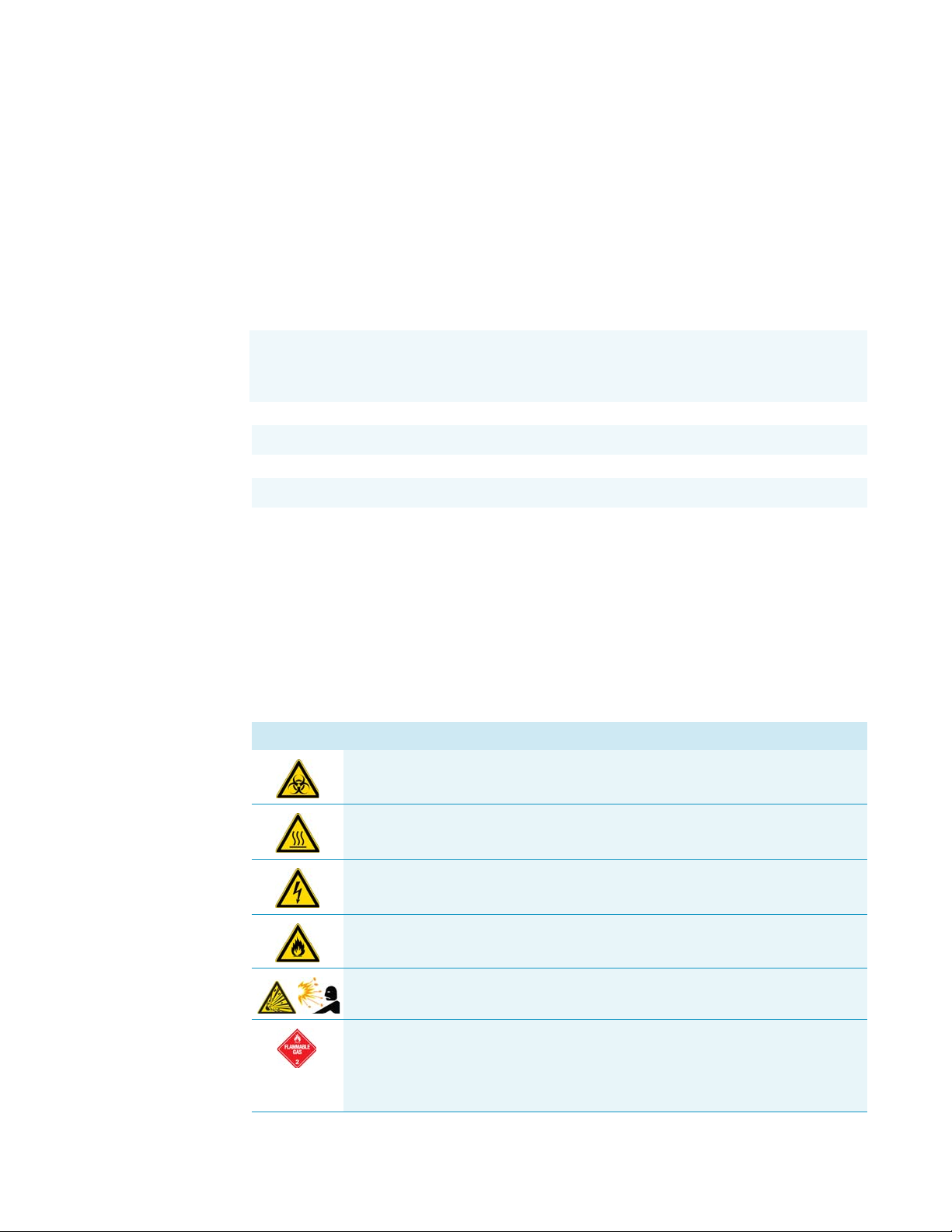
safety symbols on your instrument, or in this guide:
Symbol Descriptor
BIOHAZARD: Indicates that a biohazard will, could, or might occur.
BURN HAZARD: Alerts you to the presence of a hot surface that could or might
cause burn injuries.
ELECTRICAL SHOCK HAZARD: Indicates that an electrical shock could or
might occur.
FIRE HAZARD: Indicates a risk of fire or flammability could or might occur.
EXPLOSION HAZARD. Indicates an explosion hazard. This symbol indicates
this risk could or might cause physical injury.
FLAMMABLE GAS HAZARD. Alerts you to gases that are compressed,
liquefied or dissolved under pressure and can ignite on contact with an
ignition source. This symbol indicates this risk could or might cause physical
injury.
Thermo Scientific TriPlus RSH Hardware Manual xv
Page 16
Preface
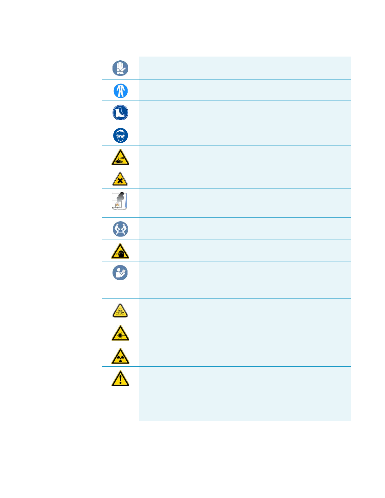
Safety Alerts and Important Information
GLOVES REQUIRED: Indicates that you must wear gloves when performing a
task or physical injury could or might occur.
CLOTHING REQUIRED. Indicates that you should wear a work clothing when
performing a task or else physical injury could or might occur.
BOOTS REQUIRED. Indicates that you must wear boots when performing a
task or else physical injury could or might occur.
MATERIAL AND EYE HAZARD. Indicates you must wear eye protection when
performing a task.
HAND AND CHEMICAL HAZARD: Indicates that chemical damage or physical
injury could or might occur.
HARMFUL. Indicates that the presence of harmful material will, could, or
might occur.
INSTRUMENT DAMAGE: Indicates that damage to the instrument or
component might occur. This damage might not be covered under the
standard warranty.
LIFTING HAZARD. Indicates that a physical injury could or might occur if two
or more people do not lift an object.
MATERIAL AND EYE HAZARD: Indicates that eye damage could or might
occur.
READ MANUAL: Alerts you to carefully read your instrument’s
documentation to ensure your safety and the instrument’s operational ability.
Failing to carefully read the documentation could or might put you at risk for a
physical injury.
TOXIC SUBSTANCES HAZARD: Indicates that exposure to a toxic substance
could occur and that exposure could or might cause personal injury or death.
LASER HAZARD. Indicates that exposure to a laser beam will, could, or might
cause personal injury.
RADIOACTIVE HAZARD. Indicates that the presence of radioactive material
could or might occur.
For the prevention of personal injury, this general warning symbol precedes
the WARNING safety alert word and meets the ISO 3864-2 standard. In the
vocabulary of ANSI Z535 signs, this symbol indicates a possible personal
injury hazard exists if the instrument is improperly used or if unsafe actions
occur. This symbol and another appropriate safety symbol alerts you to an
imminent or potential hazard that could cause personal injury.
xvi TriPlus RSH Hardware Manual Thermo Scientific
Page 17
Instrument Markings and Symbols
3
Ta b le 1 explains the symbols used on Thermo Fisher Scientific instruments. Only a few of
them are used on the TriPlus RSH. See the asterisk.
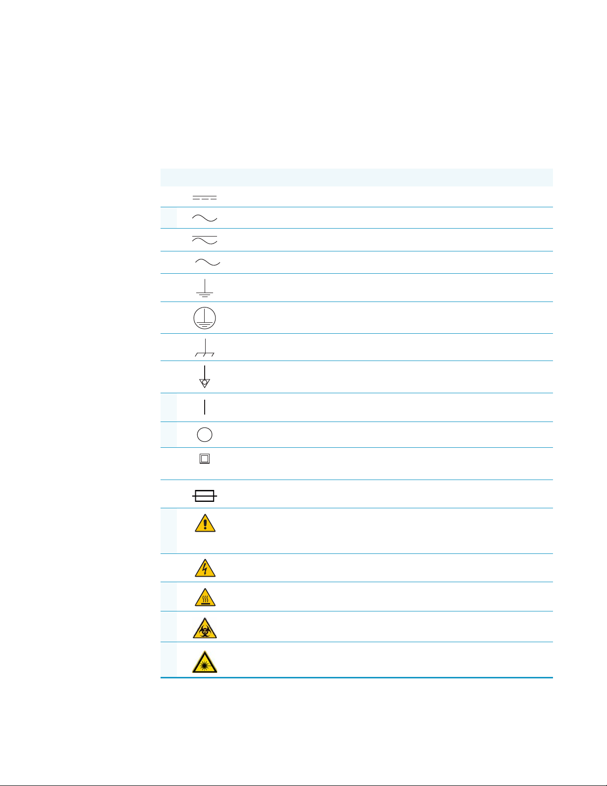
Table 1 . Instrument Marking and Symbols (Sheet 1 of 2)
Symbol Description
Direct Current
* Alternating Current
Both direct and alternating current
Three-phase alternating current
Earth (ground) terminal
Protective conductor terminal
Preface
Instrument Markings and Symbols
Frame or chassis terminal
Equipotentiality
* On (Supply)
* Off (Supply)
Equipment protected throughout by DOUBLE INSULATION or
REINFORCED INSULATION (Equivalent to Class II of IEC 536)
Fuse
* Instruction manual symbol affixed to product. Indicates that the you must
refer to the manual for specific WARNING or CAUTION information to
avoid personal injury or damage to the product.
Caution, risk of electric shock
* Caution, hot surface
* Caution, biohazard
* Caution, Laser beam
Thermo Scientific TriPlus RSH Hardware Manual xvii
Page 18
Preface
Safety Information and Warnings
Table 1 . Instrument Marking and Symbols (Sheet 2 of 2)
Symbol Description
* Symbol in compliance to the Directive 2012/19/EU on Waste Electrical
and Electronic Equipment (WEEE) placed on the European market after
August, 13, 2005.
Safety Information and Warnings
This safety guide raises awareness of potential safety issues and general points for
consideration for Thermo Fisher Scientific representatives during installation, and repair of
the TriPlus RSH, or parts of it (following the life cycle principle), as well as for the end user
TriPlus RSH in the lab during the learning phase, and in routine work.
IMPORTANT Read this section first before operating the TriPlus RSH.
General Considerations
• Before a unit is put to use, consult the TriPlus RSH User Guide and related documents
under all circumstances.
• Changes or modifications to this unit not expressly approved by the party responsible for
compliance, could void your’s authority to operate the equipment.
• Be aware that if the equipment is used in a manner not specified by the manufacturer, the
protective and safety features of the equipment might be impaired.
• The repair of instrument failures caused by operation in a manner not specified by the
manufacturer is expressly excluded from the standard warranty and service contract
coverage.
• When for technical reasons it is necessary to work on instrument parts which might
involve a potential hazard (moving parts, components under voltage, and so on.) contact
the Thermo Fisher Scientific authorized representative. In general, this type of situation
arises when access to the parts is only possible using a tool. When you perform a
maintenance operation, you must have received proper training to carry out that specific
task.
Electrical Hazards
Every analytical instrument has specific hazards. Be sure to read and comply with the
following pre-cautions. They ensure the safe and long-term use of your TriPlus RSH.
xviii TriPlus RSH Hardware Manual Thermo Scientific
Page 19
Preface
Safety Information and Warnings
The installation over-voltage category is Level II. The Level II category pertains to equipment
receiving its electrical power from the local level, such as an electrical wall outlet.
Connect the TriPlus RSH only to instruments complying with IEC 61010 safety regulations.
The power line and the connections between the TriPlus RSH and other instruments, used in
the configuration setup of the total analytical system, must maintain good electrical
grounding. Poor grounding represents a danger for the operator, and might seriously affect the
performance of the instrument.
Do not connect the TriPlus RSH to power lines that supply devices of a heavy duty nature,
such as motors, refrigerators and other devices that can generate electrical disturbances.
Use only fuses of the type and current rating specified. Do not use repaired fuses, and do not
short-circuit the fuse holder. The supplied power cord must be inserted into a power outlet
with a protective earth (ground) contact. When using an extension cord, make sure that the
cord also has an earth contact.
If the supplied power cord does not fit the local electrical socket and a replacement or adapter
has to be purchased locally, make sure that only a certified power cord is used. Any power cord
used must be certified by the appropriate local authorities.
Pay attention not to leave any cable connecting the TriPlus RSH and the chromatographic
system, or the power cord close to heated zone, such as the injector or detector heating blocks,
or the GC hot air vents.
Always replace any cable showing signs of damage with another one provided by the
manufacturer. Safety regulations must be respected.
Do not change the external or internal grounding connections. Tampering with or
disconnecting these connections could endanger you and damage the TriPlus RSH. The
instrument is properly grounded in accordance with these regulations when shipped. To
ensure safe operation, you do not must make any changes to the electrical connections or the
instrument's chassis.
Do not turn the instrument on if you suspect that it has incurred any type of electrical
damage. Instead, disconnect the power cord and contact a Thermo Fisher Scientific
representative for a product evaluation. Do not attempt to use the instrument until it has been
evaluated. Electrical damage might have occurred if the TriPlus RSH shows visible signs of
damage, exposure to any liquids or has been transported under severe stress.
Damage can also result if the instrument is stored for prolonged periods under unfavorable
conditions: for example, subjected to heat, moisture, and so on. Ensure that the power
supply/controller unit is always placed in a clean and dry position. Avoid any liquid spills in
the vicinity.
Thermo Scientific TriPlus RSH Hardware Manual xix
Page 20

Preface
Safety Information and Warnings
Before attempting any type of maintenance work, always disconnect the power cords from the
power supply(ies) if optional devices are installed. Capacitors inside the instrument might still
be charged also if the instrument is turned off.
To avoid damaging electrical parts, do not disconnect an electrical assembly while power is
applied to the TriPlus RSH. After the power is turned off, wait approximately 30 seconds
before you disconnect an assembly.
The instrument includes a number of integrated circuits. These circuits might be damaged if
exposed to excessive line voltage fluctuations, power surges or electrostatic charges, or both.
Never try to repair or replace any components of the instrument without the assistance of a
Thermo Fisher Scientific representative. There are no operator-serviceable or replaceable parts
inside the power supply(ies) or in the TriPlus RSH. If a power supply is not functioning,
contact a Thermo Fisher Scientific representative.
The power supplies for the TriPlus RSH, the Temperature Controlled Drawer have the
symbols I/O on the label for the power switch to indicate ON/OFF. If a Temperature
Controlled Drawer is installed in combination with a TriPlus RSH, a second power supply is
active in the complete system. Turning OFF the two power supplies, or pulling the two power
cords in an emergency, stop the entire TriPlus RSH.
It is important that the power supply(ies) is in a location where the power ON/OFF switch is
accessible and easy to operate, and where it is possible to unplug the AC power cord from the
power supply/wall outlet in case of emergency.
Laser Safety Information
Safety Warning for Laser Class 1 Product.
WARNING The installed Laser device is a Class 1 Laser Product.
Class 1 Laser devices are not considered to be hazardous when used for their intended
purpose. The following statement is required to comply with US and international
regulations.
CAUTION Use of controls, adjustments or performance of procedures other than those
specified herein might result in hazardous laser light exposures.
The selected Class 1 Laser for the TriPlus RSH module Barcode Reader complies with the
following regulations:
• 21 CFR1040.10 and 1040.11 except for deviations pursuant to Laser Notice No. 50,
dated July 26, 2001
xx TriPlus RSH Hardware Manual Thermo Scientific
Page 21
Other Hazards
Preface
Safety Information and Warnings
• EN60825-1:1994 + A1:2002 + A2:2001
• IEC60825-1:1993 + A1:1997 + A2:2001
The software contains a built-in safety time limit such that the laser scanning mechanism
cannot be operated in AIM mode for more than 5 continuous seconds.
To avoid injury and possible infection through contamination during TriPlus RSH operation,
keep your hands away from the syringe.
Do not operate the TriPlus RSH without the safety guard. The safety guard must be installed
for safe operation. Do not place any objects inside the area of the safety guard. Keep away
from the area around the safety guard during operation of the TriPlus RSH.
Danger of crushing to fingers and hands. To avoid injury keep your hands away from moving
parts during operation. Turn off the power to the TriPlus RSH if you must reach inside a
mechanically powered system with moving parts.
To avoid injury, observe safe laboratory practice when handling solvents, changing tubing, or
operating the TriPlus RSH. Know the physical and chemical properties of the solvents you
use. See the MSDS (Material Safety Data Sheets) from the manufacturer of the solvents being
used.
When using the TriPlus RSH, follow the generally accepted procedures for quality control
and method development.
When using the TriPlus RSH in the field of chromatographic analysis, if a change is observed
in the retention of a particular compound, in the resolution between two compounds, or in
the peak shape, immediately determine the reasons for the changes. Do not rely on the
separation results until you determine the cause of a change.
Do not operate on the instrument components that form part of the work area of the TriPlus
RSH when it is in motion.
Use caution when working with any polymer tubing under pressure:
• Always wear eye protection when near pressurized polymer tubing.
• Do not use polymer tubing that has been severely stressed or kinked.
• Do not use polymer tubing, in particular no PEEK or Tefzel tubing when using
tetrahydrofuran (THF), dimethylsulfoxide (DMSO), chlorinated organic solvents,
concentrated mineral acids such as nitric, phosphoric or sulfuric acids, or any related
compounds.
Do not use vials without a sealing cap, or microtiter or deepwell plates without a plate seal.
Vapor phase from organic solvents can be hazardous and flammable. Acidic vapor phase can
cause corrosion to critical mechanical parts.
Thermo Scientific TriPlus RSH Hardware Manual xxi
Page 22
Preface
Safety Information and Warnings
When sample vials have to undergo heating and agitation, it is important to consider the glass
quality. Use high quality glass only. Remember that depending on the application conditions,
high pressure can build up in the vial. Whenever a temperature greater than 60 °C is applied,
consider the vapor pressure of the solvent used to ensure that no excessive pressure builds up.
This is important when using a temperature above 100°C and especially at the maximum
temperature of 200 °C. Be aware that solid materials can also contain volatile compounds
such as water (humidity) which could cause build-up of excess vapor pressure.
Do not reuse headspace vials. During the process of washing the vial, micro-cracks can form
which will weaken the glass wall and increase the chances of the vial breaking.
In case of a single fault situation where the temperature control of the Agitator fails, there is
the potential danger that the device will heat up in an uncontrolled manner until it reaches
the cut-off temperature of the over temperature fuse, in this case, 240 °C. Based on this single
fault scenario, when working with flammable solvents, ensure that the solvent used has a flash
point which is 25 °C higher than the maximum potential temperature (240 °C) of the
Agitator.
When filling-up a standard reservoir or replacing a solvent such as a washing solvent, remove
the solvent reservoir bottle from the system to avoid a possible spill over the instrument.
Depending on the physical, chemical or hazardous properties of the solvent, use the
appropriate protective measures for handling.
Working with Toxic or other Harmful Compounds
WARNING Before using hazardous substances (toxic, harmful, and so on), please read the
hazard indications and information reported in the applicable Material Safety Data Sheet
(MSDS). Use personal protective equipment according to the safety requirements.
Before using dangerous substances (toxic, harmful, and so on) read the hazard indications and
information reported in the Material Safety Data Sheet (MSDS) supplied by the
manufacturer, referring to the relevant CAS (Chemical Abstract Service) number. The TriPlus
RSH requires the use of several chemical products with different hazard characteristics, which
are present in vials and syringes. Before using these substances or replacing the syringe, please
read the hazard indications and information reported in the MSDS supplied by the
manufacturer referring to the relevant CAS number.
When preparing the samples, please refer to local regulations for the ventilation conditions of
the work room.
All waste materials must be collected and eliminated in compliance with the local regulations
and directives in the country where the instrument is used.
xxii TriPlus RSH Hardware Manual Thermo Scientific
Page 23

Biological Hazards
Preface
Safety Information and Warnings
In laboratories where samples with potential biological hazards are handled, you must label
any equipment or parts thereof which might become contaminated with biohazardous
material. The appropriate warning labels are included with the shipment of the instrument.
It is your responsibility to label the relevant parts of the instrument.
When working with biohazardous materials, it is your responsibility to fulfill the following
mandatory requirements:
• Instructions on how to safely handle biohazardous material must be provided.
• Operators must be trained and made aware of the potential dangers.
• Personal protective equipment must be provided.
• Instructions must be provided on what to do in case operators are exposed to aerosols or
vapors during normal operation (within the intended use of the equipment) or in case of
single fault situations such as a broken vial.
The protective measures must consider potential contact with the skin, mouth, nose
(respiratory organs), and eyes.
Maintenance
• Instructions for decontamination and safe disposal of the relevant parts must be provided.
It is your responsibility to handle hazardous chemicals or biological compounds (including,
but not limited to, bacterial or viral samples and the associated waste), safely and in
accordance with international and local regulations.
Any external cleaning or maintenance must be performed with the TriPlus RSH turned off
and the power cord disconnected. Avoid using solvents and spraying on electrical parts. For
the removal of potentially dangerous substances (toxic, harmful, and so on) read the hazard
indications and information reported in the MSDS (Material Safety Data Sheet) supplied by
the manufacturer referring to the relevant CAS (Chemical Abstract Service) number. Use
proper protective gloves.
When working with hazardous materials such as radioactive, biologically hazardous material,
and so on, it is important to train all operators how to respond in case of spills or
contamination.
Depending on the class of hazardous material, the appropriate measures have to be taken
immediately. Therefore, the chemicals or solvents needed for decontamination have to be on
hand.
Any parts of the equipment which can potentially be contaminated, such as the sample vial
rack, syringe tool, wash module, and so on, must be cleaned regularly. The waste solvent from
cleaning and any hardware which requires to be disposed of has to be properly eliminated
with all the necessary precautions, abiding by national and international regulations.
Thermo Scientific TriPlus RSH Hardware Manual xxiii
Page 24
Preface
Safety Information and Warnings
Disposal
When preparing for decontamination, ensure that the solvent or chemical to be used will not
damage or react with the surface, dye (color) of the instrument, table or other nearby objects.
If in doubt, please contact your Thermo Fisher Scientific representative to verify the
compatibility of the type or composition of solvents with the TriPlus RSH.
Do not dispose of this equipment or parts thereof unsorted in municipal waste.
Follow local municipal waste regulations for proper disposal provisions to reduce
the environmental impact of waste electrical and electronic equipment (WEEE).
European Union customers: Call your local customer service representative responsible for the
TriPlus RSH for complimentary equipment pick-up and recycling.
WARNING The customer has to ensure that the TriPlus RSH has not been contaminated
by any hazardous chemical or biological compounds including (but not limited to)
bacteria or viruses.
Any part which had direct contact with the analytical sample must be identified and must
undergo an appropriate decontamination procedure prior to shipping for disposal.
Potentially dangerous components are: Syringes, Vials and Well Plates. Any critical parts
sent for disposal must be handled according to national laws for hazardous compounds.
The customer and the service engineer are fully responsible for enforcing these
requirements. Thermo Fisher Scientific will hold the representative, customer responsible,
or both, if these regulations are not observed.
xxiv TriPlus RSH Hardware Manual Thermo Scientific
Page 25

1
Specifications
This section provides general specifications of the TriPlus RSH.
Contents
• Electrical Specifications
• Physical Specifications
• Operating and Environmental Specifications
• Sound Pressure Level
• Hardware and Software Requirements
• TriPlus RSH System Software Requirements
Thermo Scientific TriPlus RSH Hardware Manual 1
Page 26

1
Specifications
Electrical Specifications
Electrical Specifications
The electrical specifications and the various protection classes are provided in Ta bl e 1 and
Ta b le 2 .
Table 1 . General Electrical Specifications
Parameter Requirements
Voltage 36 VDC
Current 3.2 A
Fuse T6.3 A/250 V
Table 2 . Handheld Controller Power Supply
Parameter Requirements
Input line voltage Grounded AC, 100 V to 240 V
Input line frequency 50/60 Hz
Input power 4 A
Output voltage 36 VDC
Output current 5.55 A (total for two Outlets)
• Protection Class I — Describes the insulating scheme used in the instrument to protect
the user from electrical shock. Class I identifies a single level of insulation between live
parts (wires) and exposed conductive parts (metal panels), in which the exposed
conductive parts are connected to a grounding system. In turn this grounding system is
connected to the third pin (ground pin) on the electrical power plug.
• Over Voltage Category II — Pertains to instruments that receive their electrical power
from a local level such as an electrical wall outlet.
• Pollution Degree 2 — Measure of pollution on electrical circuits that may produce a
reduction of the dielectric strength or surface resistivity. Degree 2 normally refers only to
non-conductive pollution.Occasionally, however, a temporary conductivity caused by
condensation is to be expected.
• Moisture Protection — Normal (IPXO) – PIXY means that there is NO Ingress
Protection against any type of dripping or sprayed water. The X is a place holder to
identify protection against dust, if applicable.
2 TriPlus RSH Hardware Manual Thermo Scientific
Page 27

Physical Specifications
The physical specification for the TriPlus RSH with Standard are listed in Tab l e 3.
Table 3 . Space and Load Requirements
1
Specifications
Physical Specifications
Instrument
TriPlus RSH standard X axis 46
TriPlus RSH extended X-axis 46
TriPlus RSH standard X axis
Depth (Y-axis) Width (X-axis) Height (Z-axis) Mass
cm in. cm in. cm in. kg lbs
80
1
1
1
1
18
18
1
85 33.5 54 21.3 13.3
120.5 47 54 21.3 15.3
31.5 99
2
39
2
(Working Range)
TriPlus RSH extended X-axis
80
1
31.5 135
2
53
2
(Working Range)
1
About 20 cm (about 8-in.) of the orthogonal crossrail (Y-axis) are protruding the back of the GC.
2
Dimension of the entire working range including Handheld bracket
3
Dimension including the support legs [about 22 cm (8.7 in.) height]
4
Mass without accessories.
Operating and Environmental Specifications
These specifications are listed in Ta b le 4 .
53 (74)
53 (74)
3
3
20.9 (29)
20.9 (29)
3
3
4
29.3
4
33.7
25 55
27 60
4
4
Table 4 . Operating and Environmental Specifications
Parameter Requirements
Operating temperature range 5 °C to 40 °C (41 °F to 104 °F)
Non-operating temperature range (transport or storage conditions) -25 °C to +65 °C (-13 °F to + 149 °F)
Maximum relative humidity 80%, non-condensing
Work environment Indoor use
Altitude Up to 3000 m above sea level
Mains voltage variation ±10%
Bench space At least 30 cm (12 in.) at the back.
Access to power switches and power cords. Clean, level, and smooth surface.
Clean, level and smooth surface. Solid bench plate.
Vibration Negligible
Static electricity Negligible
Thermo Scientific TriPlus RSH Hardware Manual 3
Page 28

1
Specifications
Sound Pressure Level
Sound Pressure Level
The sound pressure level is listed in Ta b le 5 .
Table 5 . Sound Pressure Level
Parameter Requirements
Sound Pressure Level Measured value:
• TriPlus RSH (basic unit): 64 dBA
• TriPlus RSH with Agitator: 66 dBA
• TriPlus RSH with Vortexer without sample vial: 67
dBA
• TriPlus RSH with Vortexer with 20 ml sample vial
inserted: 78 dBA.
One meter from the equipment in the direction of
maximum sound pressure level.
According to UL 610107A-1, 1st Edition, clause 12.5. Limit < 85 dBA
dBA = A weighted sound pressure level
Hardware and Software Requirements
This section details the hardware and software requirements.
Computer Hardware Requirements
The computer hardware minimal requirements depends on the Microsoft Windows
Operating System and, if applicable, on the MS.NET Framework software used. See
recommendations from Microsoft.
It is also important to consider the minimum requirements for the operation of the
Chromatography Data System Software (CDS).
For operation of the TriPlus RSH, both an Ethernet (TCP/IP) and a USB communication
port are required. The computer in use must be equipped accordingly: LAN or Ethernet IEEE
802.3 Industry Standard 10/100 Base-T. The network interface of the TriPlus RSH supports
the Auto-MDI(X) protocol.
The USB Device/Client Type B communication port of the TriPlus RSH is currently not
activated.
4 TriPlus RSH Hardware Manual Thermo Scientific
Page 29

USB Stick (Memory Drive)
Use a commercially available standard USB memory stick with at least 100 MB memory size.
No special formatting of the drive (stick) is necessary; on the contrary only one partition must
be defined. If two partitions are defined, subsequent errors occur, and the access to the system
is denied.
Note Commercially available USB sticks with encrypting software installed, and secure
USB drives, typically have two partitions. This type of USB drive cannot be utilized in
combination with the TriPlus RSH system.
The following software types of the USB memory drive are compatible with the TriPlus RSH:
•FAT
•FAT32
• The software NTFS is NOT supported. If a USB Stick with this software is used, the stick
will not be recognized by the RSH Firmware.
1
Specifications
Hardware and Software Requirements
• Starting with Firmware version 1.5.0 a USB Stick with software version 3.0 can be
operated. With Firmware versions lower than 1.5.0, USB sticks can be operated with
software version 2.X.X only.
• It is recommended to adjust the Allocation Unit Size as large as possible. There is a
dependency observed between the Capacity Size and the size of the Allocation Unit.
Examples: USB Stick Capacity 4 GB with 4 MB Allocation Unit, or 16 GB Capacity
with 64 MB Allocation Units. These combinations are valid; however a 16 GB Capacity
with 8 MB Allocation Units is not working. The observed effect is that the USB Stick is
not recognized within the 10 seconds time limit.
Note The Recognition Time is time used from the moment the stick is connected to
the TriPlus RSH System until the USB symbol is displayed on the handheld controller
(terminal).
Recognition Time of the USB Stick is:
• Firmware version < 1.5.0:Time-out after 10 s.
• Firmware version ≥ 1.5.0: Time-out after 30 s.
PC Software Requirements
All the software functionality such as Backup, Restore, or Update for the RSH Firmware are
performed directly via USB interface using the USB stick. For these purposes, no specific
software on a PC is required.
Thermo Scientific TriPlus RSH Hardware Manual 5
Page 30

1
Specifications
Hardware and Software Requirements
For the operation of the TriPlus RSH with a Thermo Scientific Chromatography Data System
(CDS), for example: Chromeleon, Xcalibur, ChromQuest, or Chrom-Card, a software driver
is used. The specific requirements for operation of the integrated TriPlus RSH System in the
CDS are outlined by the supplier of the CDS software.
For the operation of the TriPlus RSH in combination with Sample Control, the software from
Microsoft MS.net framework version 4.0 (or higher) is required.
Configuring Windows for Firmware and for the CDS
When configuring the Windows Operating software for the TriPlus RSH, it is important to
note that the CDS to be used in conjunction with the TriPlus RSH might require specific
settings as well. These settings have to be matched for reliable operation of the analytical
system. See the corresponding sections in the installation manual of the specific CDS.
Firewall or Virus Scanner Settings
In order to reliably operate the TriPlus RSH and the selected Chromatography Data System
(CDS), it is necessary to turn OFF any third party Firewall or Virus Scanner software.
If for any reason a firewall must be activated; the TCP Ports 80, 64000, 64001, and 8194
must be unlocked.
Screen Savers
It is highly recommended NOT to use any Screen Savers.
Disabling Power Management
Depending on the Windows Operating System version and the default settings, the computer
may enter standby mode automatically after a specified time if no mouse or keyboard activity
is detected. Using this Power Save mode in the environment with laboratory instruments
where unattended operation day and night is expected, will likely result in loss of data,
interruptions of specific functions, or whole operations.
To disable Windows power management
1. Select the Windows Control Panel
2. Select System and Security
3. Select Power Options
4. From Power Plan select the menu item Put the Computer to sleep: Never
Note Depending on the Windows version, the path or wording may differ slightly.
The example given above is based on Windows 7.
6 TriPlus RSH Hardware Manual Thermo Scientific
Page 31

TriPlus RSH System Software Requirements
The TriPlus RSH Firmware is the collective term referring to all required software and data
that complement one another and make up the complete TriPlus RSH Firmware. It consist
mainly of:
•Operating System (OS)
• TriPlus RSH Application Software
• TriPlus RSH Configuration (persisted data)
•TriPlus RSH Device Firmware
When restoring a TriPlus RSH Configuration Backup, the software packages Tri Plus R SH
Application and TriPlus RSH Configuration are saved, under the file extension *.pac.
This file is always stored as an archive file.
The Operating System and TriPlus RSH device firmware are not stored in the configuration
backup.
1
Specifications
TriPlus RSH System Software Requirements
In case of a software update for the TriPlus RSH Firmware, a single archive file with the file
extension *.cont will be supplied.
The software supplied depends on the compatibility of all the software packages. In some
cases, only the TriPlus RSH device firmware is necessary to complete the update. All other
software packages remain untouched, and are compatible. If major changes are made to the
operating systems, could also be necessary to adapt both the TriPlus RSH Application, and
the TriPlus RSH Configuration software to provide full compatibility.
Note For detailed information see the Chapter 4, “TriPlus RSH Firmware.”
Thermo Scientific TriPlus RSH Hardware Manual 7
Page 32

Page 33

2
Installation of the TriPlus RSH System
This chapter provides informations for installing the TriPlus RSH System.
Contents
• Introduction
• Installation Quick Reference Guide
• Unpacking the Components
• Installing the TriPlus RSH Supports on the GC
• Placing the TriPlus RSH on the Supports
• Installation of the TriPlus RSH System
• Installing the TriPlus RSH Head
• Installing the Handheld Controller and Safety Guard
• Installing the Purge Gas Pressure Regulator
• Installing the Tool Stations
• Installing the Wash Stations
• Installing a Tray Holder
• Installing an Agitator
• Installing a Vortexer
• Installing a MHE Station
• Installing a SPME Conditioning Station
• Installing a Barcode Reader
• Installing a Liquid Cooled Tray Holder
• Installing a Temperature Controlled Drawer
• Installing an OC Injector Module
• Inserting a LS Syringe into the LS Tool
• Inserting a HS Syringe into the HS Tool
• Installing the SPME Fiber Protector
• Inserting a SPME Fiber Holder into the SPME Tool
• Managing an ITEX Syringe and Trap Assemble
• Connecting the Power Module
• Combining the TriPlus RSH to Other Devices
• Establishing Communication with the Computer
Thermo Scientific TriPlus RSH Hardware Manual 9
Page 34

2
Installation of the TriPlus RSH System
Introduction
Introduction
This chapter describes the installation of the TriPlus RSH and its modules. Referencing of the
TriPlus RSH and teaching of the various modules are described in Chapter 3, “TriPlus RSH
Defining Object Positions.”
Who Performs the Installation
CAUTION The TriPlus RSH is installed by authorized Thermo Fisher Scientific technical
personnel, who will check its correct operation. For more details, please contact Thermo
Fisher Scientific local representatives. Should the instrument not be installed by Thermo
Fisher Scientific personnel, please strictly adhere to the following instructions.
Space Requirements
Provide enough space around the instrument on which the TriPlus RSH must be installed
making reference to the overall dimensions of the sampler described in the TriP lu s RS H
Preinstallation Requirements Guide.
WARNING Pay attention not to operate on the instrumental parts included in the work
area of the sampler when this is in movement.
Electrical Requirements
The power line and the connections between the instruments must maintain good electrical
grounding. Poor grounding represents a danger for the operator and may seriously affect the
instrument performance.
CAUTION Do not connect the TriPlus RSH to lines feeding devices of a heavy duty
nature, such as motors, UV lamps, refrigerators and other devices that can generate
disturbances.
Pay attention not to leave any cable connecting the sampling unit and the
chromatographic system or the power cord close to the GC hot air vents.
Connect the TriPlus RSH only to instruments complying with the IEC 61010 safety
regulations.
Sampler Supports
The TriPlus RSH is installed on the GC by using the two appropriate supports provided.
Every support has a bar provided with holes for the fixing on the GC, and a vertical support
leg provided with clamps for the correct hookup of the sampler.
10 TriPlus RSH Hardware Manual Thermo Scientific
Page 35

Material Required for the Installation
To install the TriPlus RSH, and its modules, the following material is required:
• T6 Torxhead screwdriver
• T10 Torxhead screwdriver
• T20 Torxhead screwdriver
• T25 Torxhead screwdriver
• Two flat wrenches
•Flat-head screwdriver
Installation Quick Reference Guide
Table 6 . Installation Quick Reference Guide (Sheet 1 of 2)
2
Installation of the TriPlus RSH System
Installation Quick Reference Guide
Step Action Reference
01 Prepare the working area and the GC System. See the relevant Preinstallation Requirements Guide for
the GC system and the TriPlus RSH.
02 Check if all components of the TriPlus RSH System are
delivered.
03 Install the TriPlus RSH supports on the GC See “Installing the TriPlus RSH Supports on the GC” on page 13
04 Install the TriPlus RSH on the GC. See “Placing the TriPlus RSH on the Supports” on page 19
05 Connect all the Active and Passive modules, to complete the
required system configuration.
06 Make all electrical connections, including for the Active
modules
07 Prepare the tool(-s). Insert the required syringe(-s). “Inserting a LS Syringe into the LS Tool” on page 53 or
08 Prepare the Computer with the required software: Follow the recommendations and specifications from Thermo
09 Connect the TriPlus RSH to the Network environment.
LAN cable provided with the system.
See “Unpacking the Components” on page 12
See “Installation of the TriPlus RSH System” on page 20
See “Installation of the TriPlus RSH System” on page 20
“Inserting a HS Syringe into the HS Tool” on page 55, or
“Inserting a SPME Fiber Holder into the SPME Tool” on page 59
“Managing an ITEX Syringe and Trap Assemble” on page 61
Fisher Scientific.
See the section Hardware and Software Requirements in
the TriPlus RSH User Guide.
See “Combining the TriPlus RSH to Other Devices” on page 68.
10 Power up the system See the section How to Start the TriPlus RSH in the Tr iP lu s
RSH User Guide.
11 When handheld controller is not part of the TriPlus RSH system:
Establish LAN Communication and Start the Virtual handheld
controller software under Xcalibur.
Thermo Scientific TriPlus RSH Hardware Manual 11
Follow the recommendations and specifications from Thermo
Fisher Scientific.
Page 36

2
Installation of the TriPlus RSH System
Unpacking the Components
Table 6 . Installation Quick Reference Guide (Sheet 2 of 2)
Step Action Reference
12 Check the RSH Firmware Version.
If the software version is lower than 1.4.0, perform an Update
procedure at the beginning of the installation. The minimum
software version should not be lower than 1.3.2.
13 Change the Access Level to Extended User See the section Access Level in the TriPlus RSH User Guide.
14 Press Options and select in the pull-up menu the item Setup |
Modules.
- Check availability of the Active modules.
- Add all required Passive modules.
- Check or add if necessary in following order:
Signal, Input/Output Interface, Chromatograph System
15 From the Start Screen select the required Tool, press Enter and
select menu item Needle Guide Type.
Note: The parameter Cap Type in the class Vial Type has to
correspond with the Tool Needle Guide Type.
Example:
Magnetic10/20 | Magnetic Cap.
Magnetic 2mL | Magnetic Cap
Foil Cutter | MTP Plates.
If Needle Guide Type is defined as Not Specified, a run is
prohibited also when the Cap Type is set No Cap or Non
Magnetic Cap.
Path from the Start Screen: Options | About. See the section
About Menu in the TriPlus RSH User Guide.
See “Update the RSH Firmware” on page 121.
See the chapter Setup Menu Item in the TriPlus RSH User
Guide.
Explanations for the different settings:
Not Specified: Prohibits the execution of a run.
Magnetic 2mL: Magnetic Transport for 2 mL vial
(large magnetic ring not installed).
Magn. 10/20 mL: Magnetic transport of 10 or 20 mL vials.
Large magnetic ring installed.
Foil Cutter: Foil Cutter for MicroTiter Plate foils installed.
16 Press Options and select in the pull-up menu the item Service |
Installation. Follow step-by-step the installation wizard.
17 Make a Backup file See the section Maintenance Menu Item- Backup in the
See the section Service Menu - Installation Item in the
TriPlus RSH User Guide.
TriPlus RSH User Guide and Chapter 4, “TriPlus RSH Firmware.”
Unpacking the Components
A TriPlus RSH is shipped into two boxes. Depending on the configuration and optional
modules, the entire system may be shipped in more than two boxes:
• The main box contains the TriPlus RSH base (X-,Y- axes assembly) and the standard
modules such as the TriPlus RSH Handheld Controller, Power Module, Tray Holders,
Trays, Wash Stations, and so on.
• The second box contains the TriPlus RSH Head (entire Z-axis). For shipping and
protective reasons, the inner mechanical part is separated from the cover.
12 TriPlus RSH Hardware Manual Thermo Scientific
Page 37

2
Installation of the TriPlus RSH System
Installing the TriPlus RSH Supports on the GC
To unpack the instrument
1. Open the boxes, remove the accessory boxes to compare the packing list, and check for
completeness of the shipment
2. Carefully lift the TriPlus RSH base and remove it from the box.
CAUTION This operation must be performed by TWO persons who must stand each on
one side of the X-axis and put their hands underneath it.
Hold the Y-axis in place while the assembly is being removed from the box. Set the
TriPlus RSH base assembly on a bench.
3. Unpack the remaining box that includes the TriPlus RSH Head. If applicable, unpack the
other boxes with any additional accessories included.
4. When placing the TriPlus RSH System onto a GC, make sure that no objects interfere
with the Y-axis, or the TriPlus RSH Head, throughout the entire potential range of
movement.
Installing the TriPlus RSH Supports on the GC
The TriPlus RSH supports are two vertical legs provided into a dedicated GC Mounting Kit.
To install the supports on your GC refer to the following procedures:
• “Installing the Supports on a Single GC” on page 14
• “Installing the Supports on a Double TRACE 1300/1310” on page 15
• “Installing the Supports on a TRACE 1300/1310 Coupled with a MS” on page 15
• “Installing the Supports on a Double TRACE GC Ultra” on page 15
• “Installing the Supports on a Double FOCUS GC” on page 16
• “Installing the Supports on a TRACE GC Ultra Coupled with a FOCUS GC” on
page 17
• “Installing the Supports on a Double TRACE GC Ultra Coupled with a MS” on page 18
• “Installing the Supports on a TRACE GC Ultra and on a FOCUS GC Coupled with a
MS” on page 18
Thermo Scientific TriPlus RSH Hardware Manual 13
Page 38

2
1
2
3
4
4
5
6
6
6
1 = Support Bar
2 = Support Leg
3 = Mounting clamps
4 = Support Leg Holes
5 = Leg Fixing Screws
6 = Support Bar Fixing Holes for the GC
Installation of the TriPlus RSH System
Installing the TriPlus RSH Supports on the GC
Sampler Supports Assembling
To assemble the sampler support
With reference to Figure 1, proceed as follows:
Figure 1. Support Assembling
.
1. Insert the provided fixing screw into each hole present on the support bar.
2. Place the support leg on the support bar paying attention that the fixing screw of the leg is
frontally turned.
3. Tighten the fixing screws.
Installing the Supports on a Single GC
To install the sampler supports on a GC
1. From the GC upper cover remove the plastic caps covering the corresponding fixing
holes.
2. Insert into each holes present on the support bar the provided fixing screw.
3. Mount each sampler support on the GC paying attention to have the support leg turned
toward the back of the GC.
4. Guide the fixing screws into the corresponding fixing holes.
5. Tighten the fixing screws.
14 TriPlus RSH Hardware Manual Thermo Scientific
Page 39

Installing the Supports on a Double TRACE 1300/1310
To install the support on a double TRACE 1300/1310 placed side by side
CAUTION Before proceeding, verify that the working area is large enough to
accommodate two GC units and possible external devices.
1. Place the two TRACE 1300/1310 side by side.
1. From the upper cover of the GC placed on the right, remove the plastic caps covering the
corresponding fixing holes.
2. Insert into each holes present on the support bar the provided fixing screw.
3. Mount each sampler support on the GC paying attention to have the support leg turned
toward the back of the GC.
4. Guide the fixing screws into the corresponding fixing holes.
2
Installation of the TriPlus RSH System
Installing the TriPlus RSH Supports on the GC
5. Tighten the fixing screws.
Installing the Supports on a TRACE 1300/1310 Coupled with a MS
To install the support on a TRACE 1300/1310 coupled with a mass spectrometer
CAUTION Before proceeding, verify that the working area is large enough to
accommodate the GC, the MS detector and possible external devices.
1. From the GC upper cover remove the plastic caps covering the corresponding fixing
holes.
2. Insert into each holes present on the support bar the provided fixing screw.
3. Mount each sampler support on the GC paying attention to have the support leg turned
toward the back of the GC.
4. Guide the fixing screws into the corresponding fixing holes. Tighten the fixing screws.
Installing the Supports on a Double TRACE GC Ultra
To install the supports on a double TRACE GC Ultra placed side by side
CAUTION Before proceeding, verify that the working area is large enough to
accommodate two GC units and possible external devices.
Thermo Scientific TriPlus RSH Hardware Manual 15
Page 40

2
Installation of the TriPlus RSH System
Installing the TriPlus RSH Supports on the GC
1. From both sides of the first GC upper cover remove the plastic caps covering the
corresponding fixing holes.
2. Insert the provided fixing screw into each hole present on the support bar.
3. Mount each sampler support on the GC paying attention to have the support leg turned
toward the back of the GC.
4. Guide the fixing screws into the corresponding fixing holes, then tighten the fixing
screws.
5. Move the second GC beside the first one leaving a distance of about 90 mm between the
two GC units.
6. From the left side of the second GC upper cover remove the plastic caps covering the
corresponding fixing holes.
7. Insert the appropriate fixing screws into each hole present on the spacer plate provided.
8. Mount the spacer plate on the two GC units.
9. Guide the fixing screws into the corresponding fixing holes, then tighten the fixing
screws.
Installing the Supports on a Double FOCUS GC
To install the sampler supports on two FOCUS GC Ultra units placed side by side,
CAUTION Before proceeding, verify that the working area is large enough to
accommodate two GC units and possible external devices.
1. Place the two FOCUS GC units side by side leaving a distance of about 130 mm between
the two GC units.
2. From the right side of each of the FOCUS GC upper cover remove the plastic caps
covering the corresponding fixing holes.
3. Insert the provided fixing screw into each hole present on the support bar.
4. Mount each sampler support on the GC units paying attention to ensure that the support
leg is turned toward the back of the GC.
5. Guide the fixing screws into the corresponding fixing holes, then tighten the fixing
screws.
6. From the left side of the second FOCUS GC upper cover remove the plastic caps
covering the corresponding fixing holes.
7. Insert the appropriate fixing screws into each hole present on the spacer plate provided.
8. Mount the spacer plate on the two GC units.
16 TriPlus RSH Hardware Manual Thermo Scientific
Page 41

2
Installation of the TriPlus RSH System
Installing the TriPlus RSH Supports on the GC
9. Guide the fixing screws into the corresponding fixing holes, then tighten the fixing
screws.
CAUTION Before proceeding, verify that the working area is large enough to
accommodate the GC units, the MS detector, and possible external devices.
For this configuration the use of the TriPlus RSH extended X-axes is required.
1. From the right side of the TRACE GC Ultra and from the left side of the TRACE GC
Ultra for MS upper cover remove the plastic caps covering the corresponding fixing holes.
2. Insert the provided fixing screw into each hole present on the support bar.
3. Mount each sampler support on the GC units paying attention to have the support leg
turned toward the back of the GC.
4. Guide the fixing screws into the corresponding fixing holes, then tighten the fixing screws
5. Place the two GC units beside the MS detector.
Installing the Supports on a TRACE GC Ultra Coupled with a FOCUS GC
To install the sampler supports on a TRACE GC Ultra alongside a FOCUS GC
CAUTION Before proceeding, verify that the working area is large enough to
accommodate two GC units and possible external devices.
1. Place the FOCUS GC on the left and the TRACE GC Ultra on the right leaving a
distance of about 57 mm between the two GC units.
2. From both sides of the TRACE GC Ultra upper cover, remove the plastic caps covering
the corresponding fixing holes.
CAUTION One of the two supports must not be assembled. If the supports have already
been assembled, one of them must be disassembled.
3. Disassemble one sampler support removing the support leg from the support bar
unscrewing the two fixing screws.
4. Mount the support leg on the spacer plate provided and fix them by using the same fixing
screws previously removed.
5. Insert the provided fixing screw into each hole present on the support bar.
6. Mount the alone support bar on the left side and the complete sampler support on the
right side of the TRACE GC Ultra paying attention to have the support leg turned
toward the back of the GC.
Thermo Scientific TriPlus RSH Hardware Manual 17
Page 42

2
Installation of the TriPlus RSH System
Installing the TriPlus RSH Supports on the GC
7. Guide the fixing screws into the corresponding fixing holes, then tighten the fixing
screws.
8. From the right side of the FOCUS GC upper cover remove the plastic caps covering the
corresponding fixing holes.
9. Insert the appropriate fixing screws into each hole present on the spacer plate assembled
with the support leg.
10. Mount the spacer plate assembling on the two GC units.
11. Guide the fixing screws into the corresponding fixing holes, then tighten the fixing
screws.
Installing the Supports on a Double TRACE GC Ultra Coupled with a MS
To install the sampler supports on two TRACE GC Ultra coupled with a mass
spectrometer
CAUTION Before proceeding, verify that the working area is large enough to
accommodate the GC units, the MS detector, and possible external devices.
For this configuration the use of the TriPlus RSH extended X-axis is required.
1. From the right side of the TRACE GC Ultra and from the left side of the TRACE GC
Ultra for MS upper cover remove the plastic caps covering the corresponding fixing holes.
2. Insert the provided fixing screw into each hole present on the support bar.
3. Mount each sampler support on the GC units. Pay attention that the support leg is
turned toward the back of the GC.
4. Guide the fixing screws into the corresponding fixing holes, then tighten the fixing
screws.
5. Place the two GC units beside the MS detector.
Installing the Supports on a TRACE GC Ultra and on a FOCUS GC Coupled with a MS
To install the sampler supports on a TRACE GC Ultra for MS and a FOCUS GC placed
on the sides of a mass spectrometer
CAUTION Before proceeding, verify that the working area is large enough to
accommodate the GC units, the MS detector, and possible external devices.
For this configuration the use of the TriPlus RSH extended X-axis is required.
1. From the TRACE GC Ultra upper cover remove the plastic caps covering the
corresponding fixing holes.
18 TriPlus RSH Hardware Manual Thermo Scientific
Page 43

2. Insert the provided fixing screw into each holes present on the support bar.
3. Mount each sampler support on the TRACE GC Ultra Pay attention that the support leg
is turned toward the back of the GC.
4. Guide the fixing screws into the corresponding fixing holes.
5. Tighten the fixing screws.
6. Place the two GC units beside the MS detector.
7. To mount the autosampler use the appropriate support and fixing it on the installation
holes provided on the top of the GC.
8. For further details please refer to the Operating Manual of the sampling system in use.
Placing the TriPlus RSH on the Supports
To place the TriPlus RSH onto the supports (vertical legs)
2
Installation of the TriPlus RSH System
Placing the TriPlus RSH on the Supports
1. Loosen the two mounting clamps Torx screws of the vertical legs.
2. Place the TriPlus RSH base assembly on top and fit the legs into the groove in the X- axis.
CAUTION This operation must be performed by TWO persons who must stand each on
one side of the X-axis and put their hands underneath it.
3. Be sure that the mounting clamps fit completely into the grooves. Alternately tighten the
two Torx screws until the legs are firmly in place.
Figure 2. Positioning and Fixing of the Mounting Clamps in the X-axis Grooves
4. Be sure that the mounting clamps fit completely into the grooves. Alternately tighten the
two Torx screws until the legs are firmly in place.
5. Double check if the leg mounting clamps are correctly hooked to the X-axis. See Figure 3.
Thermo Scientific TriPlus RSH Hardware Manual 19
Page 44

2
Correct
Wrong
Installation of the TriPlus RSH System
Installation of the TriPlus RSH System
Figure 3. Correct and Wrong Hooking of Mounting Clamps
Installation of the TriPlus RSH System
This sections details the installation of the TriPlus RSH and its modules.
Note for Field Service Engineers — Discuss with the customer the positions of the TriPlus
RSH base and the TriPlus RSH modules hooked to the X-axis considering the GC
configuration. Open zones should be easily accessible by the TriPlus RSH Head but placing
a TriPlus RSH object above a heated zone could be dangerous, or at the very least influence
the stability of the analytical sample. Consider the space availability in the lab and to
adjacent instruments as well.
WARNING Do not place a TriPlus RSH module, which might contain flammable
solvents, directly above a heated zone. Special attention has to be paid to the Wash Station
and its waste line (if applicable), and Tray Holders with sample vials inserted.
Figure 4 shows an example of TriPlus RSH system with its modules installed.
Figure 4. Example of TriPlus RSH System Modules
20 TriPlus RSH Hardware Manual Thermo Scientific
Page 45

2
Correct
Wrong
Installation of the TriPlus RSH System
Installation of the TriPlus RSH System
It is suggested to install the modules on the X-axis in the position more suitable, paying
attention not to invade the injection zone. The installed components shall not prevent the
Z-axis movements.
To Anchor the modules to the X-axis
The module to be anchored has one or two clamps. In the second case, they must be
alternately and progressively hooked. The hooking sequence is as follows:
1. Slightly tilt the component downwards in a way that the back hook of the clamp, present
on the top, enter the proper grooves.
2. Straighten the component so that also the front hook of the clamp enters the proper slot
parallel to the previous one.
3. Slightly push the component backwards in a way that the clamp hooks result perfectly
anchored. See Figure 5.
Figure 5. Correct and Wrong Hooking of Module Mounting clamps
4. Tighten the fixing screw located behind the clamp.
Thermo Scientific TriPlus RSH Hardware Manual 21
Page 46

2
Installation of the TriPlus RSH System
Installation of the TriPlus RSH System
For installing each single module refer to the following sections:
• “Installing the TriPlus RSH Head” on page 23
• “Installing the Handheld Controller and Safety Guard” on page 27
• “Installing the Purge Gas Pressure Regulator” on page 31
• “Installing the Tool Stations” on page 32
• “Installing the Wash Stations” on page 35
• “Installing the TR Station” on page 32
• “Installing the ATC Station” on page 33
• “Installing the Standard Wash Station” on page 35
• “Installing the Large Volume Wash Station” on page 36
• “Installing the Solvents Station” on page 38
• “Installing the Fast Wash Station” on page 39
• “Installing a Tray Holder” on page 40
• “Installing an Agitator” on page 41
• “Installing a Vortexer” on page 42
• “Installing a MHE Station” on page 43
• “Installing a SPME Conditioning Station” on page 45
• “Installing a Barcode Reader” on page 47
• “Installing a Liquid Cooled Tray Holder” on page 48
• “Installing a Temperature Controlled Drawer” on page 49
• “Installing an OC Injector Module” on page 51
22 TriPlus RSH Hardware Manual Thermo Scientific
Page 47

Installing the TriPlus RSH Head
Transport Locking Device
Note Installation of the TriPlus RSH Head (Z-axis) must be done carefully.
When installing it for the first time, have someone hold it in place while the mounting
screw is inserted.
IMPORTANT The head is secured with a Transport Locking Device in order to prevent
uncontrolled movement of the slider along the Z-Axis during the shipping. The locking
device must be removed before installing the head to the base.
The TriPlus RSH Head is shipped disassembled. The cover is separated from the mechanical
part.
To install the TriPlus RSH head
1. Locate the Transport Locking Device screw. Using a Torx T10 screwdriver remove the
screw and the polymer spacer. See Figure 6.
2
Installation of the TriPlus RSH System
Installing the TriPlus RSH Head
Figure 6. Transport Locking Device
Thermo Scientific TriPlus RSH Hardware Manual 23
Page 48

2
Locating Pins
Installation of the TriPlus RSH System
Installing the TriPlus RSH Head
2. Save the Transport Locking Device for future use. If for any reason the head unit has to be
returned for inspection or repair, the Transport Locking Device must be reinstalled prior
to shipping.
3. Locate the Torx mounting screw as shown in Figure 7.
Figure 7. TriPlus RSH Head Internal Mechanic Part and Cover
4. Hold the TriPlus RSH Head in place against the Y-axis. Make sure the two locating pins
on the Y-axis fit into the two guide pin holes on the TriPlus RSH Head. See Figure 8 and
Figure 9.
Figure 8. Head Mounting (1)
24 TriPlus RSH Hardware Manual Thermo Scientific
Page 49

Figure 9. Head Mounting (2)
2
Installation of the TriPlus RSH System
Installing the TriPlus RSH Head
5. Place the provided Torx mounting screw into the hole from the front and securely tighten
the screw by using the T25 Torx screwdriver provided. See Figure 10.
Figure 10. Head Mounting (3)
Note The Ribbon Cables and the Gas Purge Line within the TriPlus RSH Head are
already assembled and fixed. No installation of these parts is necessary. The Gas Purge
Line connects the Y-axis, sealed by an O-ring, to the TriPlus RSH Head.
Thermo Scientific TriPlus RSH Hardware Manual 25
Page 50

2
Installation of the TriPlus RSH System
Installing the TriPlus RSH Head
6. Locate the TriPlus RSH Head cover and put it over the mechanical construction of the
Head very carefully to avoid any damage to a ribbon cable, motor connections and other
critical parts.
7. Hold the cover in a perpendicular way and slide it over the mechanics of the Head. Avoid
angling of the cover when attaching it to the mechanics. See Figure 11.
Figure 11. Head Mounting (4)
8. Put the Head cover over the mechanical construction from the top in perpendicular path.
See Figure 12.
Figure 12. Head Mounting (5)
26 TriPlus RSH Hardware Manual Thermo Scientific
Page 51

2
Installation of the TriPlus RSH System
Installing the Handheld Controller and Safety Guard
9. Tighten the screw at the backside of the cover to fix it to its mechanical part.
See Figure 13.
Figure 13. Head Mounting (6)
Installing the Handheld Controller and Safety Guard
The Handheld Controller is an optional module for the TriPlus RSH. If it is not part of the
system configuration ordered, the TriPlus RSH can be controlled with the Virtual Handheld
Controller software. See Figure 14.
Note If the Handheld Controller is part of the configuration, it is advisable to install first
all the other modules which are connectable to the X-axis.
The Safety Guard can be installed at the end when everything else has been tested and
completed.
Thermo Scientific TriPlus RSH Hardware Manual 27
Page 52

2
Installation of the TriPlus RSH System
Installing the Handheld Controller and Safety Guard
Figure 14. Handheld Controller Installation
To install the safety guard and the handler controller
1. Install the Safety Guard brackets on the left and right side to the of the X-axis.
The brackets are installed underneath the Side Cover of the X-axis using the two holes at
back side. The two front holes are reserved for the Handheld Controller mounting
bracket. Do not completely tighten the screw to allow enough play to connect the Safety
Guard. See Figure 15.
Figure 15. Safety Guard Installation
2. Connect the Safety Guard to the brackets by using the screws provided. Keep the Safety
Guard in a square position and alternately tighten the screws from the brackets, and the
guard on either side.
28 TriPlus RSH Hardware Manual Thermo Scientific
Page 53

2
Installation of the TriPlus RSH System
Installing the Handheld Controller and Safety Guard
3. Install the Handheld Controller mounting bracket on either the right or left side of the
X-axis. See Figure 16.
Figure 16. Handheld Control Bracket Installation
By default, the Handheld Controller bracket is assembled for the right hand installation.
If the bracket is installed on the left hand side, remove the bracket from the holder,
reverse it, and install it to the backside of the holder. See Figure 17.
Figure 17. Reversing Handheld Controller Bracket for Left Side Installation
4. Connect the Handheld Controller cable to the TriPlus RSH Control Interface connector
marked Handheld Controller on the back of the X-axis. See Figure 18.
Thermo Scientific TriPlus RSH Hardware Manual 29
Page 54

2
Installation of the TriPlus RSH System
Installing the Handheld Controller and Safety Guard
Figure 18. Handheld Controller Connection
5. Place the Handheld Controller onto its mounting bracket. See Figure 19.
Figure 19. Handheld Controller Position
30 TriPlus RSH Hardware Manual Thermo Scientific
Page 55

Installing the Purge Gas Pressure Regulator
WARNING Use an inert gas, such as helium or nitrogen, as purge gas.
When working with the connections for the pressure regulator, it is mandatory to always use
two flat wrenches as shown in Figure 20. Using only one wrench increases the chances of
damaging or destroying the sealing gaskets.
Figure 20. Installation of the Purge Pressure Regulator (1)
2
Installation of the TriPlus RSH System
Installing the Purge Gas Pressure Regulator
To install the purge gas pressure regulator
1. Connect the OUT-side of the supplied pressure regulator at the back right side of the
Tr iP l us RSH . S e e Figure 21.
Figure 21. Installation of the Purge Pressure Regulator (2)
Thermo Scientific TriPlus RSH Hardware Manual 31
Page 56

2
Installation of the TriPlus RSH System
Installing the Tool Stations
2. Connect a 1/8 inch clean gas supply line to the IN-side of the pressure regulator.
Use a separate gas line to avoid any pressure drop that may affect the GC.
3. Adjust the pressure of the gas supply source to 1.0 − 1.5 bar (14.5 − 21.6 psig). If a gas
line is teed-up from an installed gas chromatograph, the preset secondary pressure will be
approximately 5 bar (72.5 psig).
4. Adjust the TriPlus RSH Autosampler gas pressure regulator to approximately 0.5 bar
(7.25 psig).
5. Check the installed purge gas pressure regulator connections for leaks. Avoid any
contamination of the pneumatic system, (gas flow), by using liquid soap or similar leak
detection aids.
Note Pressures higher than 0.5 bar (7.25 psig) will not yield higher flow rates through
the heated syringe. The syringe needle is the point of flow restriction in the gas flow
system.
The body of the pressure regulator can withstand up to 10 bar (145 psig).
Note The pressure of the purge gas should be verified during the flush period in a
Headspace Cycle.
Installing the Tool Stations
The TriPlus RSH is equipped either with a TR Station, (Passive module), containing a single
Slot, or the ATC Station, (Active module), containing three slots. The ATC Station allows the
automatic change of the TriPlus RSH tools according to the specific requests.
To install the Tool Station you want, refer to:
• “Installing the TR Station” on page 32
• “Installing the ATC Station” on page 33
Installing the TR Station
To install the TR station
Note Place the TR Station paying attention to keep enough clearance for the tool
below it to not interfere with the GC devices.
Do not place another module too close to the TR Station, keep approximately 20 mm
clearance on the left side. This space is needed for teaching the position.
1. Use the T20 Torxhead screwdriver to loosen the Torx screw on the TR Station mounting
bracket.
2. Hook the TR Station to the X-axis.
32 TriPlus RSH Hardware Manual Thermo Scientific
Page 57

Figure 22. TR Station Installation
2
Installation of the TriPlus RSH System
Installing the Tool Stations
3. Be sure that the clamp fits completely into the grooves. Tighten the Torx screw until the
mounting clamp is firmly in place. A square position of the module should be achieved.
Installing the ATC Station
To install the ATC station
Note Place the ATC Station paying attention to keep enough clearance for the tool
below it to not interfere with the GC devices.
Do not place another module too close to the ATC Station, keep approximately
20 mm clearance on the left side. This space is needed for teaching the position.
1. Use the T20 Torxhead screwdriver to loosen the two Torx screws on the ATC Station
mounting bracket.
2. Hook the ATC Station to the X-axis.
Thermo Scientific TriPlus RSH Hardware Manual 33
Page 58

2
Installation of the TriPlus RSH System
Installing the Tool Stations
Figure 23. ATC Station Installation
3. Be sure that the clamp fits completely into the grooves. Tighten alternately the two Torx
screws until the mounting clamp is firmly in place; a square position of the module must
be achieved.
4. Connect the supplied ATC Station control cable from the connector on the back side of
the ATC Station to the Control Interface connector marked BUS. If BUS connector is
already occupied, connect the cable to another Active module with an open connector.
Note It is possible to install two ATC Stations on the same TriPlus RSH to enhance
flexibility with various tools. See the following CAUTION Exceptional
Circumstances and the Chapter 3, “TriPlus RSH Defining Object Positions.”
34 TriPlus RSH Hardware Manual Thermo Scientific
Page 59

2
Installation of the TriPlus RSH System
CAUTION Exceptional Circumstances
To configure two ATC Stations follow the procedure described here:
1. Physically connect both ATC Stations at the desired position of the X-Axis.
2. Define which ATC Station shall be the ATC Station #1.
3. When the TriPlus RSH is powered off, connect the supplied control cable from the
rear side of ATC Station #1 to the connector marked Bus on the TriPlus RSH control
interface. If Bus connector is already occupied, connect the cable to another Active
module with an open connector.
4. DO NOT connect the control cable from ATC Station #2.
5. Power-up the system. The software will assign the module address to ATC station #1.
6. Turn off the system and connect the provided control cable to ATC Station #2.
7. Power-up the system again, the software will recognize the second ATC Station and
will assign the address to ATC Station2.
Installing the Wash Stations
Installing the Wash Stations
The TriPlus RSH Autosampler can be equipped with four different types of Wash Stations:
Standard, Large Volume, Solvents, and Fast. For details see the following sections:
• “Installing the Standard Wash Station” on page 35
• “Installing the Large Volume Wash Station” on page 36
• “Installing the Solvents Station” on page 38
• “Installing the Fast Wash Station” on page 39
WARNING Observe the safety measures if a Waste Line is installed in combination with a
GC. Do not position the entire Wash Station above a heated zones. Pay special attention
to the guidance of the Waste Line.
For GC, often highly flammable wash solvents are used (organic solvents such as hexane,
acetone, esters, and so on).
Installing the Standard Wash Station
To install the standard wash station
1. Use the T20 Torxhead screwdriver to loosen the screw from the Wash Station mounting
clamp.
2. Hook the Standard Wash Station assembly to the X-axis.
Thermo Scientific TriPlus RSH Hardware Manual 35
Page 60

2
Installation of the TriPlus RSH System
Installing the Wash Stations
3. Tighten the mounting screw.
4. Convert the Standard Wash Station with the Drainage Adapter.
a. Remove the Waste Vial in position 5.
b. Insert the Drainage Adapter.
The drainage adapter resembles a vial, and the material is PVDF (Polyvinylidene
fluoride). The same polymer cap (with septum inserted), used for the Wash vials, can
be used for this adapter. The drainage adapter has a stainless steel nipple connected to
the bottom. A waste tubing must be connected.
Installing the Large Volume Wash Station
To install the large volume wash station
1. Use the T20 Torxhead screwdriver to loosen the screw from the Wash Station mounting
clamp.
2. Hook the Large Volume Wash Station assembly to the X-axis.
36 TriPlus RSH Hardware Manual Thermo Scientific
Page 61

Figure 24. Large Volume Wash Station
2
Installation of the TriPlus RSH System
Installing the Wash Stations
3. Tighten the mounting screw.
4. Place the solvent reservoir bottles onto their holders.
5. Connect one end of the supplied polyethylene waste tubing to the Waste port. Place the
other end of the tubing into the waste reservoir (not supplied).
Stretch the PE tubing to make sure that no used wash solvent is trapped before the Waste
reservoir.
WARNING The Waste reservoir MUST be placed in a lower position than the Large
Volume Wash Station assembly.
Make sure that the waste liquid flows into the container without restriction.
For safety reasons, place the waste container into a collection pan.
Thermo Scientific TriPlus RSH Hardware Manual 37
Page 62

2
Installation of the TriPlus RSH System
Installing the Wash Stations
Installing the Solvents Station
To install the solvents station
1. Use the T20 Torxhead screwdriver to loosen the screw from the Wash Station mounting
clamp.
2. Hook the Solvents Station assembly to the X-axis.
Figure 25. Solvent Station
3. Tighten the mounting screw.
4. Place the solvent reservoir bottles onto their holders.
WARNING The Waste reservoir MUST be placed in a lower position than the Solvents
Station assembly.
Make sure that the waste liquid flows into the container without restriction.
For safety reasons, place the waste container into a collection pan.
38 TriPlus RSH Hardware Manual Thermo Scientific
Page 63

Installing the Fast Wash Station
The Fast Wash Station is shipped in a box separate from the system. The box also includes the
Solvent Reservoir Kit (two 1000 mL glass bottles, and a Tubing Kit).
CAUTION Do not place the station and specifically the waste line above a heated zone.
Tightly secure the waste line using a cable binder or similar item.
To install the fast wash station
1. Connect the solvent lines from the Solvent Reservoir Kit to the Inlet connectors of the
micro pump.
2. Loosen the two Torx screw on the mounting bracket for the module.
3. Hook the Fast Wash Station assembly to the X-axis.
4. Be sure that the clamp fits completely into the grooves. Alternately tighten the two Torx
screws until the mounting clamp is firmly in place.
2
Installation of the TriPlus RSH System
Installing the Wash Stations
5. Double check whether the Fast Wash Station clamp is correctly attached to the X-Axis.
Figure 26. Fast Wash Station
6. Connect the supplied control cable from the connector on the back side of the Fast Wash
Station to the Control Interface connector marked BUS. If BUS connector is already
occupied, connect the cable to another Active module with an open connector.
For details see Figure 27.
Thermo Scientific TriPlus RSH Hardware Manual 39
Page 64

2
Installation of the TriPlus RSH System
Installing a Tray Holder
Figure 27. Fast Wash Station Connections
Installing a Tray Holder
To install the tray holder
1. Use the T20 Torxhead screwdriver to loosen the two Torx screws on the two mounting
clamps.
2. Install the Tray Holder with the mounting clamp teeth fitting into the grooves on the
bottom of the X-axis.
Figure 28. Tray Holder Installation
40 TriPlus RSH Hardware Manual Thermo Scientific
Page 65

3. Alternately tighten the two Torx screws until the two mounting clamps are firmly in
place.
4. Double check if the two clamps are correctly hooked to the X-axis.
Installing an Agitator
To install the agitator
1. Loosen the two Torx screws on the two Agitator mounting clamps.
Figure 29. Installing the Agitator
2
Installation of the TriPlus RSH System
Installing an Agitator
2. Be sure that the clamps fit completely into the grooves. Alternately tighten the two Torx
screws until the two mounting clamps are firmly in place.
3. Double check if the Agitator clamps are correctly hooked to the X-axis.
4. Connect the supplied control cable (daisy chain cable) from the connector on the back
side of the Agitator to the Control Interface connector marked BUS.
If BUS connector is already occupied, connect the cable to another Active module with
an open connector. For details see Figure 30.
Thermo Scientific TriPlus RSH Hardware Manual 41
Page 66

2
Installation of the TriPlus RSH System
Installing a Vortexer
Figure 30. Agitator Electrical Connections
Installing a Vortexer
To install the vortexer
1. Loosen the two Torx screws on the two Vortex Mixer mounting clamps.
Figure 31. Installing a Vortexer Module
42 TriPlus RSH Hardware Manual Thermo Scientific
Page 67

2
Installation of the TriPlus RSH System
Installing a MHE Station
2. Be sure that the clamps fit completely into the grooves. Alternately tighten the two Torx
screws until the two mounting clamps are firmly in place.
3. Double check if the Vortexer clamps are correctly hooked to the X-axis.
4. Connect the supplied control cable (daisy chain cable) from the connector on the back
side of the module to the Control Interface connector marked BUS. If BUS connector is
already occupied, connect the cable to another Active module with an open connector.
For details see the Figure 32.
Figure 32. Vortexer Electrical Connections
Installing a MHE Station
Before starting the installation process, determine the approximate position for the MHE
Adapter Holder.
The recommended position is directly next to the Agitator keeping about 40 mm distance.
If the Agitator is located at the far right side of the X-Axis, the MHE Adapter Holder should
be placed to the left side of the Agitator, or inside the path of travel.
Likewise, if the Agitator is located at the far left, the MHE Adapter Holder should be placed
to the right of the Agitator.
Note If a venting tube is installed, the MHE Adapter Holder must be installed as close as
possible to the Agitator (or any other position where the venting of the vial is performed)
to prevent the venting tube from catching on the hardware module.
To install the MHE station
1. Loosen the Torx screw on the mounting clamps located on the top side of the Fiber
Conditioning Station.
Thermo Scientific TriPlus RSH Hardware Manual 43
Page 68

2
Installation of the TriPlus RSH System
Installing a MHE Station
2. Be sure that the clamps fit entirely into the grooves. Tighten the Torx screw until the
mounting clamps are firmly in place.
3. Double check if the MHE Adapter Holder clamp is correctly hooked to the X-axis.
Figure 33. MHE Station
4. If the application requires the waste tube, connect one end of the waste tube to the MHE
Adapter. Insert the other end into an appropriate waste container, or into an appropriate
laboratory venting system, such as a fume hood.
5. The MHE Adapter is already pre-assembled. If a venting tube is required, insert the tube
and tighten with the provided nut. A tube flange connection or a flangeless ferrule (flat
bottom) is recommended.
6. Place the MHE Adapter into the Adapter Holder, making sure that the vent outlet is
positioned within the two pins of the Adapter Holder.
7. Insert the red magnetic ring in the Injection Unit.
Figure 34. Magnet Transport Ring
44 TriPlus RSH Hardware Manual Thermo Scientific
Page 69

Installing a SPME Conditioning Station
To install the SPME Conditioning Station, proceed as follows:
Note Before starting, determine approximately where the SPME Conditioning Station
must be located.
The TriPlus RSH Head has a longer path in the Z-axis, allowing a 20 mL vial to be
completely inserted into the unit, and avoiding any collisions.
If there is not enough space between the X-axis of the TriPlus RSH and the GC top cover,
consider installing the module outside of the GC frame to the far left or far right side.
If the SPME Conditioning Station is installed with an existing TriPlus RSH, another
module might require to be shifted. Remember to re-position the modules accordingly.
To install the SPME conditioning station
1. Loosen the Torx screw on the mounting clamps located on the top side of the Fiber
Conditioning Station.
2
Installation of the TriPlus RSH System
Installing a SPME Conditioning Station
Figure 35. Installing the SPME Conditioning Station
2. Be sure that the clamps fit entirely into the grooves. Tighten the Torx screw until the
mounting clamps are firmly in place.
3. Double check if the SPME Conditioning Station clamp is correctly hooked to the X-axis.
4. Connect the supplied control cable (daisy chain cable) from the connector on the back
side of the module to the TriPlus RSH Control Interface connector marked BUS.
If BUS connector is already occupied, connect the cable to another Active module with
an open connector. For details see Figure 36.
Thermo Scientific TriPlus RSH Hardware Manual 45
Page 70

2
Installation of the TriPlus RSH System
Installing a SPME Conditioning Station
Figure 36. SPME Conditioning Station Electrical and Gas Connections
5. Connect the Gas Line
WARNING Do not use hydrogen or any other explosive gas or gas mixtures for the SPME
Conditioning Station. Recommended gases are helium or nitrogen.
a. One end of the supplied black gas tube is connected to the gas purge regulator
supplied with the TriPlus RSH. See “Installing the Purge Gas Pressure Regulator” on
page 31.
b. Remove the blind-plug at the gas purge regulator and connect the corresponding
reducing union supplied with the installation kit. The other side of the gas tube is
connected with a 1/8 inch Swagelok nut to the SPME Conditioning Station.
The installation of this second gas line is shown in Figure 37.
Figure 37. Gas Tube Connection from Pressure Regulator to SPME Conditioning Station
46 TriPlus RSH Hardware Manual Thermo Scientific
Page 71

2
Installation of the TriPlus RSH System
Installing a Barcode Reader
6. Set the Gas Flow
a. The gas flow is regulated by the Purge Gas Pressure Regulator. The setting of the
secondary regulator is approximately 0.5 bar as for Headspace analysis.
The SPME Conditioning Station has a built-in, internal flow restriction.
The typical flow rate yields about 6 mL/min if only the back position is used.
If both positions are used (front and back), the flow is divided approximately in half.
The gas flow for the two positions is pneumatically separated. Both channels can be
used independently of one other.
The restriction is a frit installed in the Swagelok union at the conditioning station
housing (connection to the gas tube). In case of blockage, clean the frit with an
intense flow of gas from the reverse side or wash it in an ultrasonic bath with an
appropriate solvent. As a good starting point, an aqueous mixture of an alcohol is
recommended for washing.
The Head needle guide, with the installed Stack Drawer Magnet and SPME Adapter,
is “sit “on the spring-loaded gas valve. At this point, the gas flow is activated.
Leaving this position will close the gas valve, minimizing gas consumption.
Installing a Barcode Reader
To install the barcode reader
1. Loosen the two Torx screws on the two Barcode Reader mounting clamps.
Figure 38. Installing the Barcode Reader
2. Be sure that the clamps fit completely into the grooves. Alternately, tighten the two Torx
screws until the two mounting clamps are firmly in place.
Thermo Scientific TriPlus RSH Hardware Manual 47
Page 72

2
Installation of the TriPlus RSH System
Installing a Liquid Cooled Tray Holder
3. Double check if the Barcode Reader clamps are correctly hooked to the X-axis.
4. Connect the supplied control cable (daisy chain cable) from the connector on the back
side of the Barcode Reader module to the TriPlus RSH Control Interface connector
marked BUS. If BUS connector is already occupied, connect the cable to another Active
module with an open connector. For details see Figure 39.
Figure 39. Barcode Reader Electrical Connections
Installing a Liquid Cooled Tray Holder
To install the liquid cooled Tray holder
1. Loosen the two Torx screws on the two module mounting clamps.
Figure 40. Installing the Liquid Cooled Tray Holder Module
48 TriPlus RSH Hardware Manual Thermo Scientific
Page 73

2. Be sure that the clamps fit completely into the grooves. Alternately tighten the two Torx
screws until the two mounting clamps are firmly in place.
3. Double check if the Liquid Cooled Tray Holder clamps are correctly hooked to the
X-axis.
4. Connect the hoses from the liquid circulation bath, tighten securely using pipe clamp.
5. Select the liquid medium for temperature control according to the application
requirements.
6. Ensure the quality of the hose, connections and consider the compatibility with the liquid
medium being circulated. Avoid any leaks or spill to prevent physical injury caused by the
coolant or possible fire.
Installing a Temperature Controlled Drawer
To install the temperature controlled drawer
2
Installation of the TriPlus RSH System
Installing a Temperature Controlled Drawer
1. Loosen the two Torx screws on the two module mounting clamps.
Figure 41. Installing the Temperature Controlled Drawer
2. Be sure that the clamps fit completely into the grooves. Alternately tighten the two Torx
screws until the two mounting clamps are firmly in place.
3. Double check if the Temperature Controlled Drawer clamps are correctly hooked to the
X-axis.
4. Power off the TriPlus RSH before making any electrical connections.
5. Connect the supplied control cable (daisy chain cable) from the connector on the back
side of the module to the TriPlus RSH Control Interface connector marked BUS.
Thermo Scientific TriPlus RSH Hardware Manual 49
Page 74

2
Installation of the TriPlus RSH System
Installing a Temperature Controlled Drawer
If BUS connector is already occupied, connect the cable to another Active module with
an open connector. For details see Figure 42.
Figure 42. Electrical Connections of Temperature Controlled Drawer
6. Connect the cable provided to the connector OUT of the Power Module (Power Supply)
marked Tri Plu s R SH .
7. Connect the other side of the cable to the Temperature Controlled Drawer at the back of
the module.
Figure 43. Correct Electrical Connections to Two Power Supply Module
50 TriPlus RSH Hardware Manual Thermo Scientific
Page 75

2
Installation of the TriPlus RSH System
Installing an OC Injector Module
WARNING It is mandatory to use the supplied Power Module to connect the
Temperature Controlled Drawer also if the second connector marked Aux of the Power
Module used for the TriPlus RSH is not occupied.
The electrical demands of the entire system are too high to be covered by a single Power
Module.
Figure 44. Forbidden Electrical Connection to a SINGLE Power Supply
8. Connect the power cable from the power connector built into the switch to the wall
outlet.
Installing an OC Injector Module
To install the OC injector module
1. Locate the OC Injector Box and the BUS daisy chain cable.
2. Locate the cable which is connected to the OC Adapter and should be ready to hand at
the backside of the GC unit.
3. Place the OC Electronic Box preferable to the backside of the GC frame. Use a cable strap
for fixation.
4. Connect the supplied control cable (daisy chain cable) from the connector of the OC
Electronic Box to the TriPlus RSH Control Interface connector marked BUS.
If BUS connector is already occupied, connect the cable to another Active module with
an open connector. For details see Figure 45.
Thermo Scientific TriPlus RSH Hardware Manual 51
Page 76

2
Installation of the TriPlus RSH System
Installing an OC Injector Module
Figure 45. Connecting the OC Electronic Box
5. Connect the cable from the OC Adapter to the OC Electronic Box.
52 TriPlus RSH Hardware Manual Thermo Scientific
Page 77

Inserting a LS Syringe into the LS Tool
To insert a LS syringe into the LS tool
1. Remove the retaining nut from the LS Tool, then insert the syringe such that the flat side
of the flange matches with the cut-out of the upper part of the holder. See Figure 46.
Figure 46. Syringe Insertion into LS Tool
2
Installation of the TriPlus RSH System
Inserting a LS Syringe into the LS Tool
2. Carefully insert the syringe body guiding the needle tip into the upper and the lower
needle guide. Press the syringe flange firmly into the tool holder.
Thermo Scientific TriPlus RSH Hardware Manual 53
Page 78

2
O-Ring
Installation of the TriPlus RSH System
Inserting a LS Syringe into the LS Tool
Figure 47. Syringe Alignment and Front View
3. Tighten the retaining nut.
4. Check for the correct installation. It is important that the needle tip is not visible outside
of the lower needle guide. See Figure 48.
Figure 48. Correct and Incorrect Position of the Syringe Needle Tip
54 TriPlus RSH Hardware Manual Thermo Scientific
Page 79

Inserting a HS Syringe into the HS Tool
To insert a HS syringe into the HS tool
1. Remove the retaining nut from the HS Tool, locate the O-ring, and put it over the syringe
glass barrel up to the flange. This is a protection for the glass flange. See Figure 49.
Figure 49. Preparing HS-Syringe for Installation
2
Installation of the TriPlus RSH System
Inserting a HS Syringe into the HS Tool
2. Insert the HS syringe into the HS Tool. Carefully insert the syringe body guiding the
needle tip into the upper and lower needle guide.
3. Press the syringe firmly into position, and tighten the syringe flange with the retaining
nut until a resistance is felt. The plunger is inserted in the syringe barrel.
Note It is not necessary to pay attention to the position of the syringe barrel side hole.
The heater design with the O-ring sealing allows a circular purge gas flow.
4. Check for correct installation. It is important that the needle tip is not visible outside of
the lower needle guide. See Figure 50.
Thermo Scientific TriPlus RSH Hardware Manual 55
Page 80

2
Installation of the TriPlus RSH System
Inserting a HS Syringe into the HS Tool
Figure 50. Correct and Incorrect Position of the Syringe Needle Tip
Purge Gas Adapter
The purge gas adapter, mounted on the HS Tool, couples with the adapter from the TriPlus
RSH Head. See Figure 51 and Figure 52. The coupling is sealed through an O-ring installed
in the HS Tool Purge Gas Adapter.
Figure 51. HS Tool Gas Adapter
56 TriPlus RSH Hardware Manual Thermo Scientific
Page 81

2
Figure 52. Purge Gas Coupling of HS Tool and TriPlus RSH Head
Installation of the TriPlus RSH System
Installing the SPME Fiber Protector
Installing the SPME Fiber Protector
The installation of the SPME fiber protector is only valid for the tool SPME and Fiber
Holder supplied by Supelco™.
Using the tool SPME 2 the fiber protector not necessary. Returning the SPME 2 Tool into
the Park Station is the SPME Fiber not exposed anymore at the moment of decoupling the
tool.
CAUTION When a ATC Station is used, it is mandatory to install the SPME Tool and the
SPME Fiber Protector in Slot position # 1.
This limitation is due to the automated return of a tool if it must exchanged.
The TriPlus RSH always searches for the first available Slot to park the connected tool.
When the SPME Tool is originally positioned in Slot position #1, this position is available
when the SPME Tool is returned.
It is important to pay attention to the installation procedure of the SPME Protector.
Any misalignment between SPME Tool and Protection Adapter can cause Fiber breaking.
To install the SPME fiber protector
Install the SPME fiber Protector as shown in Figure 53 and Figure 54.
Thermo Scientific TriPlus RSH Hardware Manual 57
Page 82

2
Installation of the TriPlus RSH System
Installing the SPME Fiber Protector
Figure 53. SPME Fiber Protector
Figure 54. Alignment of SPME Fiber Protector
IMPORTANT It is recommended to install the SPME Fiber Protector before mounting the
TR Station or the ATC Station on the TriPlus RSH.
1. Connect the upper part of the Fiber Protector to the bottom side of the TR Station or in
Slot position #1 when a ATC Station is used. Do not tighten the screw completely
allowing a play for the alignment.
2. Insert the SPME Tool into the Slot position. The magnetic ring has to collapse into the
guiding ring of the protection adapter.
3. Very carefully, tighten the screws of the adapter ensuring that the alignment is not lost.
4. Very carefully, manually check the fiber fits perfectly into the Protection Adapter.
If not, repeat step 3 and 4.
58 TriPlus RSH Hardware Manual Thermo Scientific
Page 83

SPME2
SPME 1
Inserting a SPME Fiber Holder into the SPME Tool
5. Install the TR Station or the ATC Station on the TriPlus RSH as described in the section
“Installing the Tool Stations” on page 32.
6. Manually, check again the fiber matches with the Protector.
Inserting a SPME Fiber Holder into the SPME Tool
To insert a SPME fiber holder into the SPME tool
Note The standby position of the SPME Fiber Holder is reversed compared to a syringe.
If the plunger is in the uppermost position, the fiber is pulled back into the sheet needle.
This is the protected position for the fiber.
1. Remove the retaining nut and the SPME Tool Adapter. Insert the SPME Fiber Holder,
making sure the fiber is also inserted.
2. Insert the SPME Tool Adapter such that it sits on the metallic part of the SPME Fiber
Holder. See Figure 55 and Figure 56.
2
Installation of the TriPlus RSH System
Figure 55. Inserting Fiber Holder
Thermo Scientific TriPlus RSH Hardware Manual 59
Page 84

2
SPME 1
SPME2
Installation of the TriPlus RSH System
Inserting a SPME Fiber Holder into the SPME Tool
Figure 56. SPME Fiber Holder Inserted in SPME and SPME2 Tools
3. Place the holder such that the shaft of the moving part is visible from the front. Note that
this point is for convenience only.
4. Tighten the retaining nut to the mechanical stop. Use normal force, do not overtighten
the nut.
5. Check for correct installation. It is important that the needle tip is not visible outside of
the lower needle guide. Avoid moving the SPME plunger, the fiber could become
damaged. See Figure 57.
Figure 57. Correct and Incorrect Position of the SPME Needle Tip
The holder is fixed in position by the SPME Tool Adapter and the retaining nut. No O-rings
are necessary to fix or protect the SPME holder.
60 TriPlus RSH Hardware Manual Thermo Scientific
Page 85

Managing an ITEX Syringe and Trap Assemble
Fitting Seal
ITEX Trap
ITEX Syringe
a
b
c
d
This section provides information for installing the ITEX syringe and trap into the ITEX
Tool, for removing the HS syringe from the ITEX tool, for setting the flush gas pressure.
See the related topic:
• “Installing the ITEX Syringe and Trap into the ITEX Tool” on page 61
• “Removing the HS syringe from the ITEX Tool” on page 63
• “Flush Gas Considerations” on page 63
Installing the ITEX Syringe and Trap into the ITEX Tool
To install an ITEX syringe and trap into the ITEX tool
1. Assemble the ITEX Syringe with trap/needle following the order shows in Figure 58.
Figure 58. ITEX Syringe and Trap Assembling
2
Installation of the TriPlus RSH System
Managing an ITEX Syringe and Trap Assemble
a. Slide the seal provided with the ITEX trap on the bottom of the trap up to reach the
b. Carefully insert the ITEX trap into the ITEX syringe as far as goes.
c. Slide the fitting on the ITEX trap up to reach the tip of the syringe, then secure the
d. Internal view of the assemble where the ITEX trap is coupled with the ITEX syringe.
2. Remove the retaining nut from the tool, locate the O-ring and put it over the syringe glass
barrel up to the flange. This is a protection for the glass flange. See Figure 59.
Thermo Scientific TriPlus RSH Hardware Manual 61
stopper.
assemble by screwing the manually fitting into the syringe without overtightening.
Page 86

2
Installation of the TriPlus RSH System
Managing an ITEX Syringe and Trap Assemble
Figure 59. Syringe Insertion into the ITEX Tool
3. Insert the ITEX syringe into the ITEX Tool. Lower the syringe body carefully to guide
the needle tip into the upper and lower needle guide.
4. Press the syringe firmly into position and tighten the syringe flange with the Retaining
Nut until resistance is felt. The plunger is inserted in the syringe barrel.
Note It is not necessary to pay attention to the position of the syringe barrel side
hole. The heater design with the O-ring sealing allows a circular purge gas flow.
5. Check for correct installation. It is important that the needle tip is not visible outside of
the lower needle guide. See Figure 60.
Figure 60. Correct and Incorrect Position of the ITEX Syringe Needle Tip
62 TriPlus RSH Hardware Manual Thermo Scientific
Page 87

Removing the HS syringe from the ITEX Tool
To remove the HS syringe from the ITEX tool
1. Remove the retaining nut from the tool. See Figure 61.
Figure 61. HS Syringe Removal
2
Installation of the TriPlus RSH System
Managing an ITEX Syringe and Trap Assemble
2. Carefully slide the ITEX Syringe Removal tool under the syringe flange and pull the
syringe out of the ITEX tool.
Flush Gas Considerations
A gas flow level greater than 6 mL/min can destroy the bed of the trap, which will result in
non-reproducible trapping efficiency.
Setting Flush Gas Pressure
A gas flow restrictor union for the pressure regulator is integrated within the PAL3-ITEX
Tool. This restriction allows a flow of approximately 7 mL/min helium or approximately
5 mL/min nitrogen at a pressure setting of 0.5 bar at room temperature.
Thermo Scientific TriPlus RSH Hardware Manual 63
Page 88

2
Installation of the TriPlus RSH System
Managing an ITEX Syringe and Trap Assemble
Note If you already have installed a pressure regulator in the pressure regulator body, it is
necessary to remove this and replace it with the original adapter without a built-in flow
restriction frit, otherwise the gas flow will be too low. See Figure 62.
Figure 62. Replacing Flow-restricted Adapter at the Pressure Regulator with the Original
Adjusting Gas Flow
Adapter
If your system was previously used for static headspace techniques, you must adjust the gas
flow to ITEX technique requirements. If the original adapter for Headspace (without flow
restriction) is in place, it is likely that the pressure setting of 0.5 bar needs to be lowered.
Adjust the gas flow to approximately 4 mL/min ±1 mL/min.
This flow of gas will not damage the bed of the trap, but the entire system is flushed about
three times per minute. Standard flush time is two minutes. This means that the ITEX device
is flushed six times with gas for cleaning purposes.
Gas flow adjustment without an installed restrictor can be done. See “To adjust the gas flow”
on page 64.
To adjust the gas flow
This procedure is necessary in case the ITEX Kit is installed, if the restriction frit was not
provided, or if it has been lost or is clogged.
1. Release the pressure entirely from the pressure regulator. Use a liquid (e.g. n-hexane) to
check whether any bubbles form.
2. Turn the pressure on very slowly and check for bubble formation in the liquid again.
If a good stream of bubbles is visible, measure the gas flow.
Flush Gas Type
For gas chromatographic technique, three different carrier gases are typically used: nitrogen,
helium, and hydrogen.
64 TriPlus RSH Hardware Manual Thermo Scientific
Page 89

Flush Gas Quality
2
Installation of the TriPlus RSH System
Managing an ITEX Syringe and Trap Assemble
Nitrogen and helium are inert gases and therefore can be safely used as flush gases for the
ITEX technique.
Because of a slightly lower solubility in water, the preferred gas for headspace analysis is
helium. Whenever possible, helium should be used for the ITEX technique. If helium is used
as a carrier gas, the carrier gas line can be divided and teed-up for a carrier and a flush gas.
Activating the flush gas valve should not result in irregularities in the GC detector baseline.
WARNING Hydrogen, widely used as a carrier gas for GC capillary techniques, is a
flammable, explosive gas. For safety reasons do not use hydrogen as a flush gas for the
ITEX technique.
The minimum quality level is grade 55 (99.9995% purity).
Grade 59 (99.9999% purity) or Grade 60 (99.99990% purity) are preferable.
Good laboratory practice is to install a charcoal and a moisture filter to ensure that a high
quality of gas is supplied to the GC system.
Thermo Scientific TriPlus RSH Hardware Manual 65
Page 90

2
Installation of the TriPlus RSH System
Connecting the Power Module
Connecting the Power Module
WARNING Always switch the TriPlus RSH Power Module OFF before connecting or
disconnecting any TriPlus RSH accessories cables.
To connect the power module
1. Locate the power supply module.
2. Connect the provided cable to the connector OUT of the Power Module.
Figure 63. Power Supply Connection
Note The second outlet marked AUX of the Power Module is identical to the TriPlus
RSH outlet, including connector size and pins, and outlet voltage.
3. Connect the other side of the cable to the connector marked Power at the backside of the
Tr iP l us RSH .
4. Connect the power cable from the power connector built into the switch to the wall
outlet.
5. Make sure that the cable from Handheld Controller is correctly connected to the control
board.
6. Make sure that all the active modules are linked together (daisy chaining) and that the
first module, for example the ATC Station, is connected to the connector marked BUS as
shown in Figure 64.
66 TriPlus RSH Hardware Manual Thermo Scientific
Page 91

Figure 64. Modules Electrical Connection
2
Installation of the TriPlus RSH System
Connecting the Power Module
Thermo Scientific TriPlus RSH Hardware Manual 67
Page 92

2
Installation of the TriPlus RSH System
Combining the TriPlus RSH to Other Devices
Combining the TriPlus RSH to Other Devices
Combining the TriPlus RSH with a GC requires synchronization of a Ready-Signal and a
relay contact output signal.
This section explains the available input and output signals, the pin allocations of the external
connectors, and provides information enabling you to copy the default signals and add, for
example, a second output signal if required.
Synchronization and Output Signals
Synchronization signals are inputs that inform the TriPlus RSH to wait or to proceed with a
sample-processing step.
Output signals are sent from the TriPlus RSH to the external devices, such as the GC, to
indicate the status or the completion of the processing steps.
To setup the synchronization signals
The synchronization signals from the system to the GC must be set step-by step.
1. Assign an Input and an Output signal, and establish the type of contact required to
receive or send a signal. Type of contacts are a TTL (Transistor-Transistor Logic), a relays
contact, an Opto-coupler or another type.
The required parameters such as Pulse Duration and Blocking Time must be added.
2. An output signal is required to send a start signal to the GC. Typically the Switch Out
Signal 1 (SWOut1) is used for this task.
The assigned signals must be matched with the pin allocation of the synchronization
cable.
A second output signal, named Destination Aux, can be used for cases where one
command is sent to two different GC which must be started at the same time.
A Y-shape synchronization cable is required for connecting the TriPlus RSH to the GCs.
One signal used could be SWOut1 and the second signal would be SWOut2.
The assigned signals have to be matched with the pin allocation of the synchronization
cable.
Synchronize the signal parameters with the GC System.
Refer to the section Input/Output Interface and to the section Signal in the Tri Pl us R SH
User Guide. The Ready signal is usually sent from the GC to the system; a TTL-In signal
is used to receive the Ready signal. Depending on the GC settings, the signal is set to
active high or active low.
3. Bundle the required Input Signal and Output Signals for the GC System. The bundle
can be configured and tested in the combination of the system, and the other device.
The bundling is described in the section Chromatograph System in the Tr iP lu s R SH
User Guide as the last step in setting up signals.
68 TriPlus RSH Hardware Manual Thermo Scientific
Page 93

External Connectors
The external connectors of the control interface are shown inFigure 65.
Figure 65. Control Interface Connectors
2
Installation of the TriPlus RSH System
Combining the TriPlus RSH to Other Devices
For details refer to the section TriPlus Basic Information and to the section Setup Menu
Item in the TriPlus RSH User Guide.
The connectors are the follows:
• Handheld Controller Connector
• USB Host Connector
• USB Device/Client Connector
• Ethernet Connector
• Bus Connector
• Interface Connector
• Fuse Port
• Power Connector
Thermo Scientific TriPlus RSH Hardware Manual 69
Page 94

2
Installation of the TriPlus RSH System
Combining the TriPlus RSH to Other Devices
Handheld Controller Connector
The pin-out of the Handheld Controller 20-pin display port connector, marked
HANDHELD CONTROLLER is list in Ta b l e 7 .
Table 7 . Handheld Controller Connector Pin-out
Connector Layout Pin Signal Name
1TxOut0-
2 Term_nPresent
3TxOut0+
4TxOut1-
5GND
6TxOut1+
7TxOut2-
8GND
9TxOut2+
10 TxClkOut-
11 GND
12 TxClkOut+
13 +3.3 VDC
14 GND
15 +3.3 VDC
16 GND
17 Term_RxExt
18 +3.3 VDC
19 GND
20 Not connected
70 TriPlus RSH Hardware Manual Thermo Scientific
Page 95

USB Host Connector
The pin-out of the 4-pin USB Type A connector, marked is list in Ta bl e 8 .
Table 8 . USB Host Connector Pin-out
Connector Layout Pin Signal Name
USB Device/Client Connector
The pin-out of the 4-pin USB Type B connector, marked is list in Tab l e 9 .
Table 9 . USB Device/Client Connector Pin-out
2
Installation of the TriPlus RSH System
Combining the TriPlus RSH to Other Devices
1+5VDC
2 Data-
3 Data+
4GND
Ethernet Connector
The pin-out of the 8-pin RJ45 connector, marked is list in Ta bl e 1 0. Currently this
connector is not active.
Table 1 0. Ethernet Connector Pin-out
Connector Layout Pin Signal Name
1VCC
2 Data-
3 Data+
4GND
Connector Layout Pin Signal Name
1
2
3
4
5
TX+
TX-
RX+
NC
NC
6
7
8
Thermo Scientific TriPlus RSH Hardware Manual 71
RX-
NC
NC
Page 96

2
Installation of the TriPlus RSH System
Combining the TriPlus RSH to Other Devices
Bus Connector
The pin-out of the Bus 14-pin Mini Delta Ribbon connector, marked BUS is list in Ta bl e 1 1 .
Table 1 1. BUS Connector Pin-out
Connector Layout Pin Signal Name
1TXD
2NC
3 +36VDC
4 +36VDC
5 +36VDC
6 +36VDC
7 +36VDC
8RXD
Interface Connector
The pin-out of the Interface 15-pin DSUB female connector, marked INTERFACE is list in
Ta b le 1 2 .
Table 1 2. Interface Connector Pin-out (Sheet 1 of 2)
Connector Layout Pin Signal Name
9nAlarm
10 GND
11 GND
12 GND
13 GND
14 GND
1 TTLOut1
2 TTLOut3
3Relais1A
4Relais1B
5Relais2B
6OptoIn+
7 TTLIn1
8GND
72 TriPlus RSH Hardware Manual Thermo Scientific
Page 97

Fuse Port
2
Installation of the TriPlus RSH System
Combining the TriPlus RSH to Other Devices
Table 1 2. Interface Connector Pin-out (Sheet 2 of 2)
Connector Layout Pin Signal Name
9 TTLOut2
10 GND
11 TTLIn2
12 Relais2A
13 TTLIn3
14 OptoIn-
15 +5VDC
In the control interface a T6.3A; 250 V; 5 x 20 mm fuse is installed.
Power Connector
The pin-out of the 3-pin KYcon KPJX-3S-S connector, marked POWER is list in Ta bl e 1 3.
Table 1 3. Power Connector Pin-out
Pin Signal Name
1 VCC
2 Data-
3 Data+
Thermo Scientific TriPlus RSH Hardware Manual 73
Page 98

2
Installation of the TriPlus RSH System
Establishing Communication with the Computer
Establishing Communication with the Computer
This section provides instruction for establishing communication between the TriPlus RSH
and the computer.
Connecting the TriPlus RSH with Factory Settings
In order to select the required network setup best suited for the your’s laboratory setting, the
following possibilities are available:
• Direct connection — The TriPlus RSH is directly connected to the computer via the
LAN cable. There is no corporate network or router connection.
– IP Address TriPlus RSH: 192.168.99.230
– IP Address computer: 192.168.99.210
– Subnet Mask: 255.255.255.0
– Default Gateway: not required, leave the field empty (if an address is entered, it will
not be used)
• Corporate Network with DHCP Protocol — Ask the network administrator to verify
and integrate the setup within a corporate network.
Select the DHCP Protocol, the network assignees an IP Address and a Subnet Mask to
the TriPlus RSH.
• Corporate Network with Fixed IP Address — Ask the network administrator to provide
the IP Address, the Subnet Mask, and the Default Gateway to configure the TriPlus RSH
within the corporate network.
To establish communication to the computer, please see to the following sections:
• “Setting Up the Direct Connection” on page 75
• “Setting up the Network Interface” on page 76
• “Setting up the Network Interface by using the Handheld Controller” on page 77
• “Restoring Factory Default Network Settings” on page 77
• “Setting up a Corporate Network” on page 78
74 TriPlus RSH Hardware Manual Thermo Scientific
Page 99

Setting Up the Direct Connection
CAUTION The following description assumes that an Ethernet cable is connected directly
from the TriPlus RSH to a computer and not integrated within a customer network. If
this is the case, consult your System Administrator for support. The same is true as soon as
the DHCP Mode is activated.
This description is also valid for use with the Virtual Handheld Controller.
The System is pre-configured to use a static IP Address. To set the initial Ethernet settings,
prepare a network computer in the same IP Subnet:
To setup the direct connection
1. If the computer is already part of your network, record its TCP/IP configuration settings.
Figure 66. Setting IP Properties in the Computer
2
Installation of the TriPlus RSH System
Establishing Communication with the Computer
2. Configure the computer with a static IP Address 192.168.99.230, and a Subnet Mask
255.255.255.0. Do not enter a Default Gateway address.
Note Use the proposed IP Address number as shown in Figure 66.
If a deviation is required, do not use the following numbers of the last address package:
• 192.168.99.0 is reserved for Net address
192.168.99.255 is reserved for Broadcast address
192.168.99.230 is reserved for TriPlus RSH
3. Connect the Ethernet cable from the control board of the TriPlus RSH to the computer,
and verify that the LAN control LED lights when connected to a powered-on computer.
See Figure 67.
Thermo Scientific TriPlus RSH Hardware Manual 75
Page 100

2
Installation of the TriPlus RSH System
Establishing Communication with the Computer
Figure 67. LAN Cable Connection to the PC
Note If the communication is not established, use a Cross Adapter for the LAN
cable. The adapter can be connected on either side.
Setting up the Network Interface
To configure the ethernet port of the computer for LAN access
1. Establish a LAN connection from the computer to the TriPlus RSH by opening a
browser, and entering http://192.168.99.230 in the address field.
2. Configure the IP Address settings as shown in Figure 68.
Figure 68. LAN Communication Settings
3. Click Apply to confirm the changes, and activate the new network settings.
76 TriPlus RSH Hardware Manual Thermo Scientific
 Loading...