

Page 1

Page 2

Page
2
Installation, use and maintenance guide
SlimQuadro Idra 14
INDEX
1 - INTRODUCTION .................................................................................................................................. 7
1.1 GENERAL GUIDELINES .................................................................................................................................. 7
1.2 SAFETY GUIDELINES ..................................................................................................................................... 7
1.2.2 GENERAL WARNINGS ............................................................................................................................................................ 8
1.3 TRANSPORTATION AND STORAGE .............................................................................................................. 8
2 – TECHNICAL CHARACTERISTICS* .................................................................................................... 9
3 – GENERAL DESCRIPTION .................................................................................................................11
3.1 OPERATING TECHNOLOGY ......................................................................................................................... 11
3.2 THE PELLET ................................................................................................................................................... 11
3.3 THE FEEDBOX ............................................................................................................................................... 11
3.4 MAIN COMPONENTS OF THE APPLIANCE ................................................................................................. 12
4 - INSTALLATION ..................................................................................................................................13
4.1 APPLIANCE LOCATION ................................................................................................................................. 13
4.2 UNPACKING THE APPLIANCE ..................................................................................................................... 13
4.3 GLUING THE GLASS PANES TO THE FRONT PANEL ............................................................................... 14
4.4 REMOUNTING THE FRONT PANEL ............................................................................................................. 14
4.5 HANDLE .......................................................................................................................................................... 15
4.6 WALL MOUNT INSTALLATION ...................................................................................................................... 15
5 –HYDRAULIC CONNECTION ...............................................................................................................17
5.1 HYDRAULIC DIAGRAM .................................................................................................................................. 17
5.1.1 GUIDELINES FOR PLANTS WITH ZONE VALVES ................................................................................................................ 18
5.2 HYDRAULIC DIAGRAM WITH HEATING ONLY ........................................................................................... 19
5.3 EXAMPLE OF HYDRAULIC DIAGRAM WITH INTERSPACED BOILER COILS OR BOILER COILS .......... 20
5.4 EXAMPLE OF HYDRAULIC DIAGRAM WITH BOILER COILS AND HEATING SYSTEM ........................... 21
5.5 HYDRAULIC DIAGRAM WITH THERMOCELL (OR THERMOPUFFER) + ADDITIONAL THERMOPUFFER +
HIGH TEMPERATURE HEATING AND LOW TEMPERATURE HEATING. ................................................ 22
5.6 INSTRUCTIONS FOR EXECUTING THE HYDRAULIC SYSTEM CLOSED EXPANSION TANK ................ 23
6 – USE OF THE APPLIANCE .................................................................................................................24
6.1 DESCRIPTION OF THE CONTROL PANEL .................................................................................................. 24
6.2 DESCRIPTION OF THE POWER PANEL ...................................................................................................... 26
6.3 DATE/TIME: SETTING THE DATE AND TIME .............................................................................................. 26
6.4 CHRONO: ON/OFF PROGRAMMING ............................................................................................................ 26
6.5 LEVEL: OPERATING LEVEL SETTING ......................................................................................................... 29
6.6 THERMOCONTROL: CONTROLLING A PUFFER ........................................................................................ 29
6.7 ACS SUMMER: ACTIVATION OF THE BOILER TUBE CONTROL FROM A CHRONO COMMAND .......... 31
6.8 T.AMBIENT: CONTROLLING THE ROOM TEMPERATURE ........................................................................ 32
6.9 THERMO ACS: CONTROLLING A CONFIGURED BOILER TUBE IN A SYSTEM ...................................... 33
6.10 OPERATION OF THE GENERATOR ........................................................................................................... 35
6.10.1 DESCRIPTION OF THE OPERATING STAGES ................................................................................................................... 35
6.10.2 SETTING RANGE ................................................................................................................................................................. 36
6.10.3 AUTOMATIC CYCLE ............................................................................................................................................................ 36
6.10.4 MANUAL OPERATING CYCLE ............................................................................................................................................. 37
6.11 SWITCHING ON THE APPLIANCE .............................................................................................................. 37
6.12 SWITCHING OFF THE APPLIANCE ............................................................................................................ 37
Page 3

Page
3
Installation, use and maintenance guide
SlimQuadro Idra 14
7 ADDITIONAL ROOM TEMPERATURE THERMOSTAT / ADDITIONAL CHRONOTHERMOSTAT (not
supplied) ................................................................................................................................................. 38
7.1 OPERATING WITH THE ADDITIONAL ROOM TEMPERATURE THERMOSTAT (NOT SUPPLIED ) ....... 38
7.2 OPERATING WITH THE ADDITIONAL CHRONOTHERMOSTAT (NOT SUPPLIED) .................................. 38
8 CLEANING AND MAINTENANCE ........................................................................................................ 40
9 – SMOKE DISCHARGE TUBE AND VENTILATION OF THE ROOMS ................................................ 42
9.1 FOREWORD ................................................................................................................................................... 42
9.2 ROOM VENTILATION .................................................................................................................................... 42
9.2.1 VENTILATION FROM ADJOINING ROOMS ........................................................................................................................... 42
9.2.2 SINGLE OR MULTIPLE VENTILATION DUCTING ................................................................................................................. 42
9.3 SMOKE OUTLET ............................................................................................................................................ 43
9.3.1 CHIMNEY TYPES ................................................................................................................................................................... 43
9.3.2 FLUE OUTLET / FLUE SYSTEM COMPONENTS .................................................................................................................. 43
9.3.3 CONTROLS PRIOR TO INSTALLING THE APPLIANCE ........................................................................................................ 44
10 – ALARMS .......................................................................................................................................... 46
11 - ELECTRICAL WIRING ..................................................................................................................... 47
12 - INFORMATION FOR THE SKILLED TECHNICIAN .......................................................................... 48
12.1 MAIN COMPONENTS AND THEIR POSITION ........................................................................................... 48
12.2 GUIDELINES FOR CORRECT INSTALLATION .......................................................................................... 48
12.3 TROUBLESHOOTING CAUSE / SOLUTION ................................................................................ 50
13 SPARE PARTS ................................................................................................................................... 52
13.1 SPARE PARTS (part 1/3) ............................................................................................................................. 52
13.2 SPARE PARTS (part 2/3) ............................................................................................................................. 53
13.3 SPARE PARTS (part 3/3) ............................................................................................................................. 54
13.4 KEYS ............................................................................................................................................................. 55
Page 4

Page
4
Installation, use and maintenance guide
SlimQuadro Idra 14
DICHIARAZIONE DI CONFORMITA'
DECLARATION OF CONFORMITY
La THERMOROSSI S.P.A., VIA GRUMOLO N° 4 36011 ARSIERO (VI), sotto la sua esclusiva responsabilità
DICHIARA che l’apparecchiatura descritta in appresso:
DECLARES that the product:
Descrizione
Description
Stufa a pellet
Pellet stove
Marchio
Trademark
THERMOROSSI S.P.A.
Modello
Model
SLIMQUADRO IDRA 14
è conforme alle disposizioni legislative che traspongono le seguenti Direttive:
• 2004/108/CE (Direttiva EMC)
• 2006/95/CE (Direttiva Bassa Tensione)
• 2011/65/EU (Direttiva RoHS 2)
is in accordance with the following Directives:
• 2004/108/EC Directive (EMC Directive)
• 2006/95/EC Directive (Low Voltage Directive)
• 2011/65/EU Directive (RoHS 2)
e che sono state applicate tutte le norme e/o specifiche tecniche di seguito indicate
and that all the following standards have been applied
EN 55014-1 EN 60335-1 EN 50581
EN 61000-3-2 EN 60335-2-102 EN 62233
EN 61000-3-3
Ultime due cifre dell’anno in cui è affissa la marcatura CE 14
Last two figures of the year of the CE marking
Luogo Arsiero
Place
Data 13/05/2014
Date
Firma
Sign.
Page 5

Page
5
Installation, use and maintenance guide
SlimQuadro Idra 14
DICHIARAZIONE DI PRESTAZIONE
DECLARATION OF PERFORMANCE
Dichiarazione di prestazione in accordo con il Regolamento (UE) 305/2011
Declaration of performance according to Regulation (EU) 305/2011
N° 54
1
Codice di identificazione unico del prodotto-tipo:
Unique identification code of the product type:
SLIMQUADRO IDRA 14, apparecchio per il riscaldamento domestico, con acqua, alimentato a
pellet di legno
SLIMQUADRO IDRA 14, residential space heating appliance with water fired by wood pellets
EN 14785:2006
2
Numero di tipo, lotto , serie o qualsiasi altro elemento che consenta l'identificazione del prodotto da
costruzione ai sensi dell'articolo 11, paragrafo 4:
Type, batch or serial number or any other element allowing identification of the construction
product as required under Article 11( 4):
SLIMQUADRO IDRA 14
3
Uso o usi previsti del prodotto da costruzione, conformemente alla relativa specifica tecnica
armonizzata, come previsto dal fabbricante:
Intended use or uses of the construction product, in accordance with the applicable harmonised
technical specification, as foreseen by the manufacturer:
Apparecchio per il riscaldamento domestico, con acqua, alimentato a pellet di legno
Residential space heating appliance with water fired by wood pellets
4
Nome, denominazione commerciale registrata o marchio registrato e indirizzo del fabbricante ai
sensi dell'articolo 11, paragrafo 5:
Name, registered trade name or registered trade mark and contact address of the manufacturer as
required pursuant Article 11( 5):
THERMOROSSI S.P.A. Via Grumolo, n° 4 36011 Arsiero (VI)
5
Sistema o sistemi di valutazione e verifica della costanza della prestazione del prodotto da
costruzione di cui all'allegato V:
System or systems of assessment and verification of constancy of performance of the construction
product as set out in Annex V:
Sistema 3 e 4 / System 3 and 4
6
Nel caso di una dichiarazione di prestazione relativa ad un prodotto da costruzione che rientra
nell'ambito di applicazione di una norma armonizzata:
In case of the declaration of performance concerning a construction product covered by a
harmonised standard:
L' organismo notificato TÜV Rheinland Energie und Umwelt GmbH N° 2456 ha determinato il
prodotto-tipo in base a prove di tipo secondo il sistema 3 ed ha rilasciato il rapporto di prova
K10852013T1
The notified laboratory TÜV Rheinland Energie und Umwelt GmbH N° 2456 performed the
determination of the product type on the basis of type testing under system 3 and issued test report
K10852013T1
Page 6
Page
6
Installation, use and maintenance guide
SlimQuadro Idra 14
7
Prestazione dichiarata / Declared performance
Specifica tecnica armonizzata:
Harmonized technical specification:
EN 14785:2006
Caratteristiche Essenziali
Essential characteristics
Prestazione / Performance
Sicurezza antincendio / Fire safety
Reazione al fuoco / Reaction to fire A1
Distanza da materiali combustibili
Distance to combustible materials
Minime distanze / Minimum distances (mm):
posteriore / rear = 200
lati / sides = 200
frontale / front = 800
soffitto / ceiling = pavimento / floor = -
Rischio di fuoriuscita di braci incandescenti
Risk of burning fuel falling out
Passa / Pass
Emissione di prodotti della combustione
Emission of combustion products
CO 61,5 mg/m3 Alla potenza termica nominale / Nominal heat
output
CO 143,7 mg/m3 Alla potenza termica ridotta / Reduced heat
output
Temperatura superficiale / Surface temperature
Passa / Pass
Sicurezza elettrica / Electrical safety
Passa / Pass
Pulizia / Cleanability
Passa / Pass
Pressione massima di esercizio
Maximum operating pressure
2,5 bar
Temperatura fumi a potenza termica nominale
Flue gas temperature at nominal heat output
T 124°C
Resistenza meccanica (per sopportare un camino/una
canna fumaria)
Mechanical resistance (to carry a chimney/flue)
NPD {Nessuna Prestazione Determinata}
Potenza termica nominale / Nominal heat output 13,33 kW
Potenza termica resa in ambiente / Room heating output 1,46 kW
Potenza termica ceduta all’acqua / Water heating output 11,87 kW
Rendimento
Efficiency
93,27 % Alla potenza termica nominale / Nominal heat output
95,48 % Alla potenza termica ridotta / Reduced heat output
8
La prestazione del prodotto di cui ai punti 1 e 2 è conforme alla prestazione dichiarata di cui al
punto 7. Si rilascia la presente dichiarazione di prestazione sotto la responsabilità esclusiva del
fabbricante di cui al punto 4
The performance of the product identified in points 1 and 2 is in conformity with the declared
performance in point 7. This declaration of performance is issued under the sole responsibility of
the manufacturer identified in point 4
Firmato a nome e per conto del fabbricante da
(nome e funzione)
Signed for and on behalf of the manufacturer
(name and title)
Luogo/Place Data/Date
Arsiero 13/05/2014
Page 7
Page
7
Installation, use and maintenance guide
SlimQuadro Idra 14
1 - INTRODUCTION
1.1 GENERAL GUIDELINES
This installation, use and maintenance guide is an integral and essential part of the product and must be kept by the user. Before
commencing with the installation, use and maintenance of the product, carefully read this guide. All local, national and European
regulations regarding the installation and use of the appliance must be met. The Manufacturer recommends carrying out all the
maintenance operations described in this manual.
This appliance must only be used as intended by the manufacturer. Any other use is considered incorrect and therefore hazardous;
consequently, the user shall be totally liable for the product if used improperly. Installation, maintenance and repairs must be carried
out by professionally qualified personnel, certified according to Decree no. 37 of 22 January 2008 and in compliance with current
regulations. In case of repairs only original spare parts supplied by the manufacturer must be used. Incorrect installation or poor
maintenance can injure or damage people, animals or things; in this case the manufacturer shall be relieved of all responsibility.
Before beginning any cleaning or maintenance operation switch off the appliance by means of the 0/I switch located on the power
panel and disconnect the plug from the electrical power socket. The product must be installed in locations suitable for fire-fighting
and furnished with all the services (power and outlets) which the appliance requires for a correct and safe operation. Any repairs or
actions carried out on any systems, components or internal parts of the appliance, or on any of the accessories supplied with it, that
are not specifically authorised by Thermorossi S.p.A, will automatically void the warranty and the manufacturer's responsibility,
pursuant to Italian Decree no. 224 of the President of the Republic of 24/05/1988, art. 6/b.
It is recommended to keep this manual in a safe place that is easily accessible to all users; if the manual is lost or deteriorated
contact the manufacturer for a replacement copy. If the appliance is sold or transferred to another user ensure that the manual is
handed over with it.
Thermorossi S.p.A. retains copyright on this manual. These instructions may not be reproduced or communicated to third parties or
used in any other way without the necessary authorisation.
1.2 SAFETY GUIDELINES
PERSONAL INJURY
This safet y symbol identifies important messages throughout the manual. Read the information
marked by this symbol carefully as non-observance of this message can cause serious injury to
persons using the appliance.
DAM AGE TO PROPERTY
This safety symbol identifies messages or instructions that are fundamental for the generator to
function well. To avoid serious damage to the appliance adhere strictly to these instructions.
INFORMATION
This symbol indicates important instructions for good functioning of the generator. If this information
is not correctly observed, the performance of the appliance will not be satisfactory.
1.2.1 RECOMMENDATIONS
Before using the appliance, carefully read every section of this installation, use and maintenance guide as knowledge
of the information and the regulations contained in it are essential for a correct use of the appliance.
The entire operation concerning the connection of the electric panel must be carried out by expert personnel; no
responsibility will be accepted for damages, even to third parties, if the instructions for installation, use and
maintenance of the appliance are not followed scrupulously. Modifications made to the appliance by the user or on
his behalf, must be considered to be under his complete responsibility. The user is responsible for all the operations
required for the maintenance of the appliance before and during its use.
Page 8
Page
8
Installation, use and maintenance guide
SlimQuadro Idra 14
1.2.2 GENERAL WARNINGS
Attention: the appliance must be connected to a system provided with a PE conductor (in compliance with the
specifications of 2006/95/EC, concerning low voltage equipment).Before installing the appliance check the efficiency
of the earth circuit of the power supply system.
Attention: the power supply line must have a section which is suitable for the power of the equipment. The cable section must in any
case be no less than 1.5 mm². The appliance requires powering with a voltage of 230V and 50 Hz. Voltage variations greater than
10% of the nominal value can cause irregular operation or damage the electrical device.
Position the appliance so that the electric power outlet in the room is easily accessible. Ensure that a suitable differential switch is
installed upstream from the equipment.
Your appliance has obtained the CE marking and has been made to run for 1 hour to check that it functions correctly.
The product must not be used by children, by persons with physical or mental impairments, by persons who are not familiar with the
instructions for use and maintenance of the product (the instructions are found in this booklet).
ATTENTION: Before every use make sure that the burner is clean, and check that the ash pan is clean, check that the firebox door
is closed.
ATTENTION: the door must always remain shut tight when the stove is operating. It is strictly forbidden to open the door while the
appliance is in operation. While the appliance is in operation the smoke exhaust pipes and some parts of the appliance itself can
reach extremely high temperatures: do not touch them! Do not expose your body to hot air for long, do not overheat the room in
which the appliance is installed, as these actions could cause health problems. Do not expose plants or animals directly to the hot
air flow as this could have noxious effects on them. It is strictly prohibited to use any type of fuel (liquid, solid...) to light up the
appliance: lighting must occur automatically as intended and described in this installation, use and maintenance booklet;
consequently, it is also strictly forbidden to feed pellets (or any other material) into the brazier. Do not place non-heat resistant or
inflammable or combustible objects in the vicinity of the appliance: keep them at a suitable distance. Do not place wet clothing to
dry on the appliance. When using a clothes horse, keep at a suitable distance. It is strictly prohibited to disconnect the appliance
from the electrical power mains.
Warning: do not wet the appliance and do not touch the electrical parts with wet hands. Never vacuum hot ash: this
could damage the vacuum device. All the cleaning operations described in this manual must be carried out when the
appliance is cold.
Attention! Warning for Swiss users
Refer to the local cantonal regulations imposed by the Fire Department (Mandatory signalling and safety distances )
and the Note concerning installation of heaters issued by the Association of Cantonal Fire Agencies (VKF - AEAI).
ATTENTION: it is mandatory to earth the appliance. If this instruction is not observed serious damage, which is not
covered by warranty, will result to the body of the appliance. Have an electrician check the earthing. There must be
no electric potential (Volt) between the earth of the generator and the actual earth of the plant. To avoid
electrochemical corrosion of the appliance’s body when wet it is prohibited to use galvanised pipes or fittings.
Dedicated ground wires must be used to ground all other materials.
1.3 TRANSPORTATION AND STORAGE
TRANSPORTATION AND HANDLING
The appliance body must always be in a vertical position when handled and exclusively by means of trolleys. Take special care to
protect the electric panel, the glass, and all the fragile parts from mechanical impact which could damage them and their correct
functioning.
STORAGE
The appliance must be stored in a humid-free environment and sheltered from the weather; avoid placing the appliance directly on
the ground. The Company denies all responsibility for damage caused to wood floors or floors made from any other material.
It is inadvisable to store the product for long periods of time.
Page 9

Page
9
Installation, use and maintenance guide
SlimQuadro Idra 14
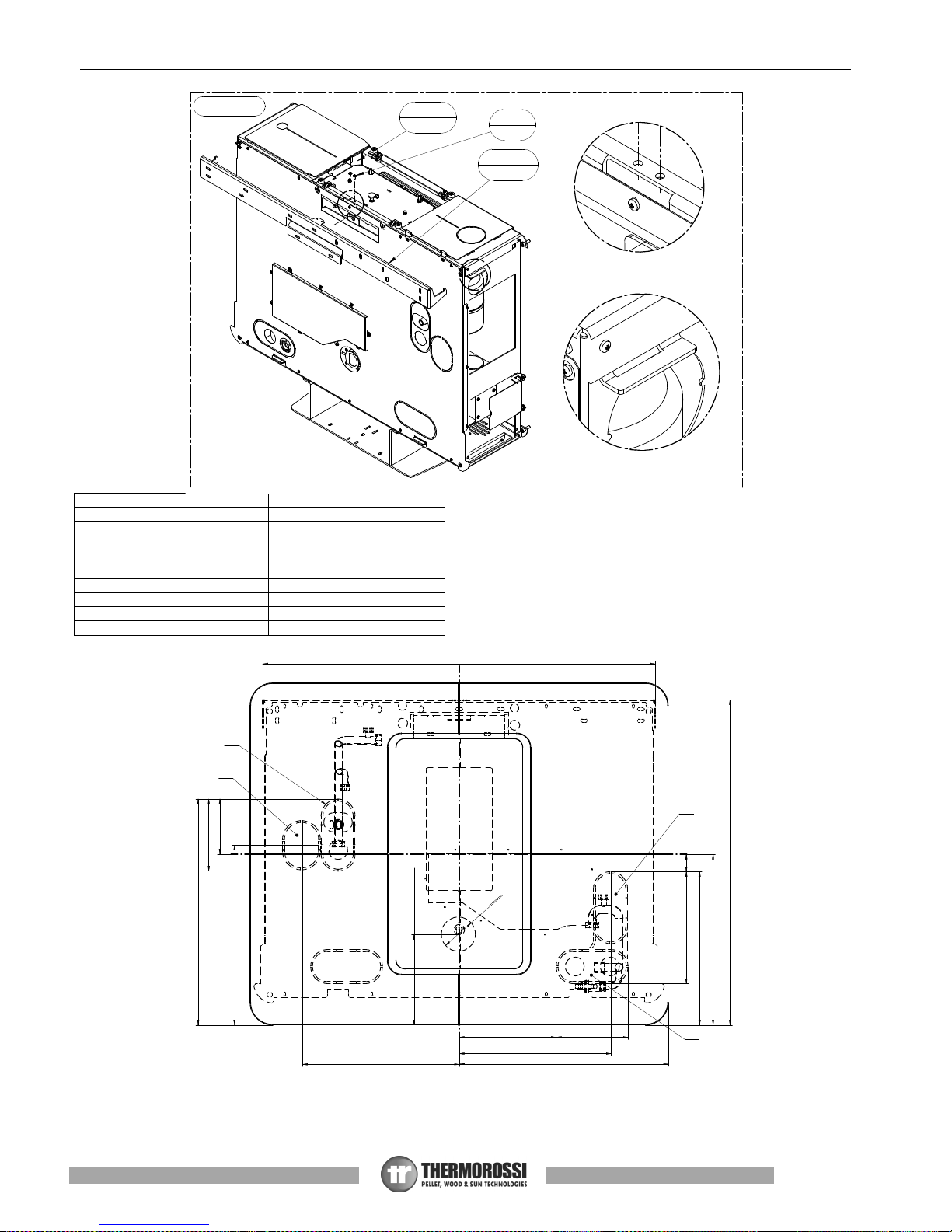
2 – TECHNICAL CHARACTERISTICS*
SLIMQUADRO IDRA 14
Height (mm) 991
Depth (mm) 315
Width (mm) 1109
Empty weight of the appliance (Kg) 164
Firebox power Min. / Max. (KW) 4.89 / 14.29
Rated power Min. / Max. (KW) 4.67 / 13.33
Power output to the room Min. / Max. (kW) 0.60 / 1.46
Min/Max consumption (Kg/ h) 1.1 / 3.1
Ø smoke exhaust pipe (mm) 80
Min. draught at rated power (Pa) 10
Min. draught at reduced power (Pa) 10
Tank capacity (Kg) 18.1
Water content (l) 21.5
Operating pressure (bar) 1.5
Max. operating pressure (bar) 2.5
Average smoke temperature at rated power (°C) 124
Average smoke temperature at reduced power (°C) 68
Max delivery water temperature (°C) 80
Min water return temperature (°C) 55
Smoke flow at rated power (Kg/sec) 9.6
Smoke flow at reduced power (Kg/sec) 5.5
Efficiency at rated power (%) 93.27
Efficiency at reduced power (%) 95.48
CO concentration in exhaust gas with 13% O2 at rated power (mg/m³) 61.5
CO concentration in exhaust gas with 13% O2 at reduced power (mg/m³) 143.7
Power supply voltage and frequency
230 V - 50
Hz
Max. electrical consumption (W) 340
Minimum electrical consumption (W) 90
Electrical consumption in standby (W) 4.8
Heatable volume (m3)** 360
* All the data are based on the appliance fuelled with EN 14961 standard type-approved pellets.
** Important: take into consideration the fact that the heatable volume is greatly influenced by the insulation of the house,
i.e. the energy class of the building and by the position of the appliance in the planimetry of the house. The indicated
values, therefore, can vary considerably.
Page 10
Page
10
Installation, use and maintenance guide
SlimQuadro Idra 14
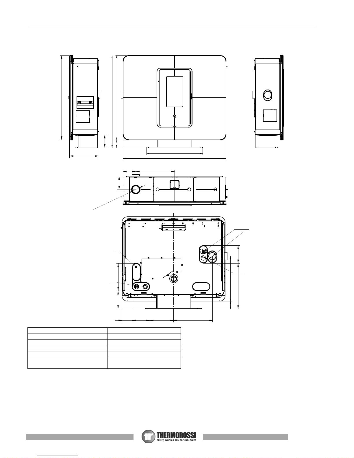
Legenda
Key
FUMI SMOKE
VALVOLA SICUREZZA 1/2'’ F. SAFETY VALVE 1/2'’ F.
RITORNO 3/4 ‘’F RETURN 3/4 ‘’F
MANDATA 3/4 ‘’F DELIVERY 3/4 ‘’F
CARICO
SCARICO 3/4” M
INLET
OUTLET 3/4” M
O
8
0
-
F
U
M
I
48484
90884
600
1109
989
416
MANDATA
3/4" F
VALVOLA
SICUREZZA
1/2" F
RITORNO
3/4" F
CARICO
SCARICO
3/4" M
295195
256189110
492 190
908
140
314
138 416
146.5
O
8
0
-
F
U
M
I
Page 11
Page
11
Installation, use and maintenance guide
SlimQuadro Idra 14
3 – GENERAL DESCRIPTION
3.1 OPERATING TECHNOLOGY
Your appliance has been built to fully satisfy all your heating and practical requirements. Top-grade components and functions
managed with microprocessor technology guarantee high reliability and optimal performance.
3.2 THE PELLET
The appliance is fuelled by pellets, that is, cylinders of compressed sawdust; it his allows you to fully enjoy the heat of the flame
without having to manually stoke the combustion.
The pellets have a 6 mm diameter and a maximum length of 15 mm. They have a maximum moisture content of 8%; thermal value
4000/4500 Kcal/Kg and density of approx. 620-630 Kg/m³.
It is strictly forbidden to use any pellet type other than that specified above. The use of fuel that does not comply with the
above specifications not only immediately invalidates the warranty for the appliance but can also create dangerous
situations. Do not use the appliance as an incinerator, at the risk of voiding the warranty.
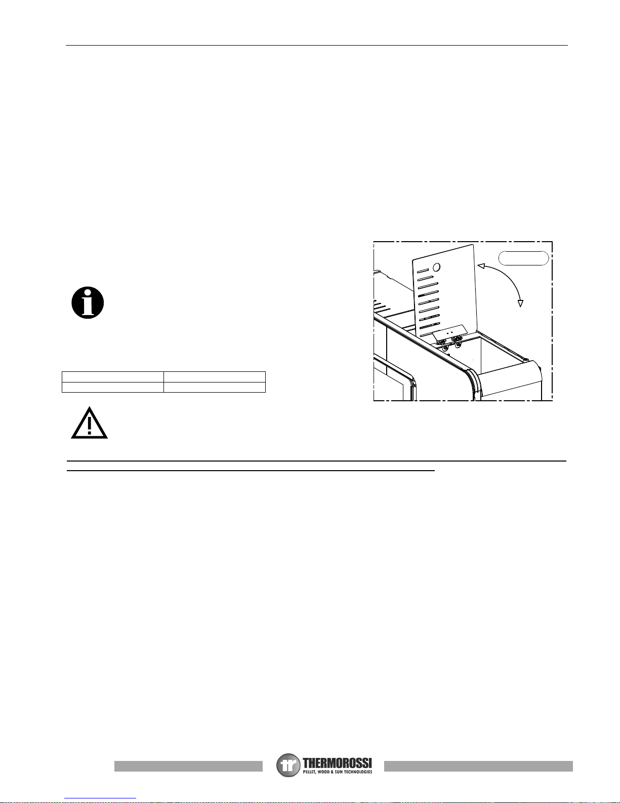
3.3 THE FEEDBOX
The feedbox is situated in the top part of the appliance (Figure
1). The load capacity specified in the technical data can vary
according to the specific weight of the pellets.
Take special care when loading the tank as the screw feeder at
its base is in motion. Take care when topping up with fuel as the
loading area can get very hot.
ATTENTION: it is normal to find some pellets remaining in the
tank even if the stove shuts off because the pellets have run
out.
Legenda
Key
Figura Figure
Attention: when filling up the tank, take care not to drop any pellets into the internal parts of the appliance, as, in
extreme cases, this could generate live flames.
The manufacturer recommends emptying the tank and vacuuming the screw feeder zone once a month and during
the summer period.
Only pellets complying with the above specifications are to be loaded into the tank; in no case whatsoever must foreign
substances or objects be introduced into the tank, the brazier or any part of the generator.
Figura 1
Page 12
Page
12
Installation, use and maintenance guide
SlimQuadro Idra 14
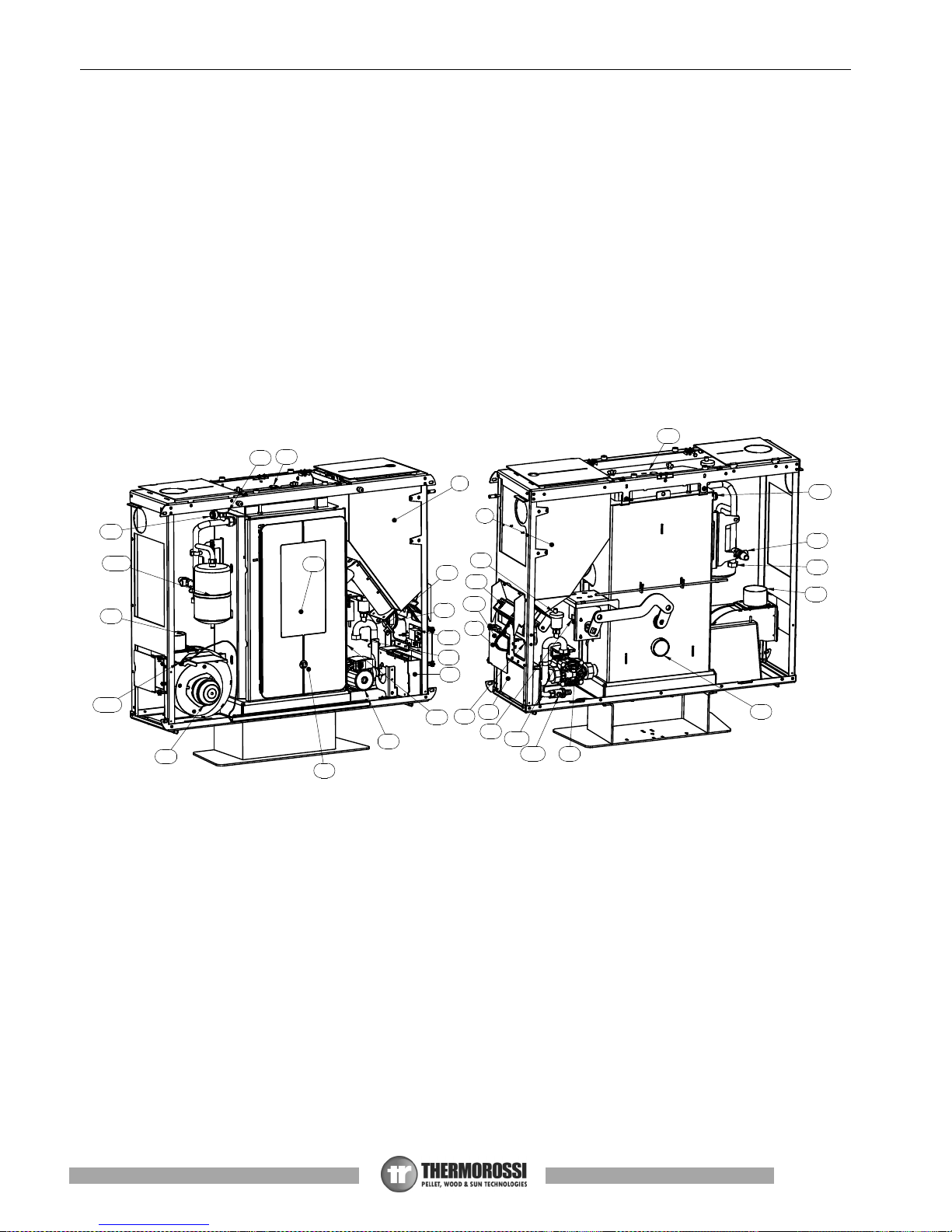
3.4 MAIN COMPONENTS OF THE APPLIANCE
A Burner cleaning motor
O
Pocket for heating system PTC sensor and
thermostat bulb 100°C reset
B System circulating pump
P Automatic relief valve
C Smoke suction unit
Q Tube bundle inspection cover
D Smoke exhaust pipe
R Control panel
E Combustion air exhaust tube
S Spiral tube scraper lever
F Smoke exhaust pressure switch
T Ash pan
G Safety thermostat 100°C
U Combustion chamber / Patented burner
H Pellet loading motor
W 3/4" fill/drain tap
I Pellet tank
X Y
Plant water return
1/2" pressure safety valve 3000 mbar
J Main switch
K Plant water delivery
AD Smoke temperature sensor
L Electronic power board
AC
Expansion tank 2 l for protection of the
appliance only
N Glow plug
A
B
B
C
D
D
E
F
F
H
G
I
I
G
J
K
L
L
N
O
O
P
P
Q
R
S
T
U
W
X
W
Y
AD
AC
Page 13
Page
13
Installation, use and maintenance guide
SlimQuadro Idra 14
4 - INSTALLATION
4.1 APPLIANCE LOCATION
Follow the general guidelines set out in paragraph 1.1 to the letter. Above all keep in mind that the flooring of the
room in which the stove is being installed must withstand the weight of the stove with the added weight of the pellet
load and the water contained in it.
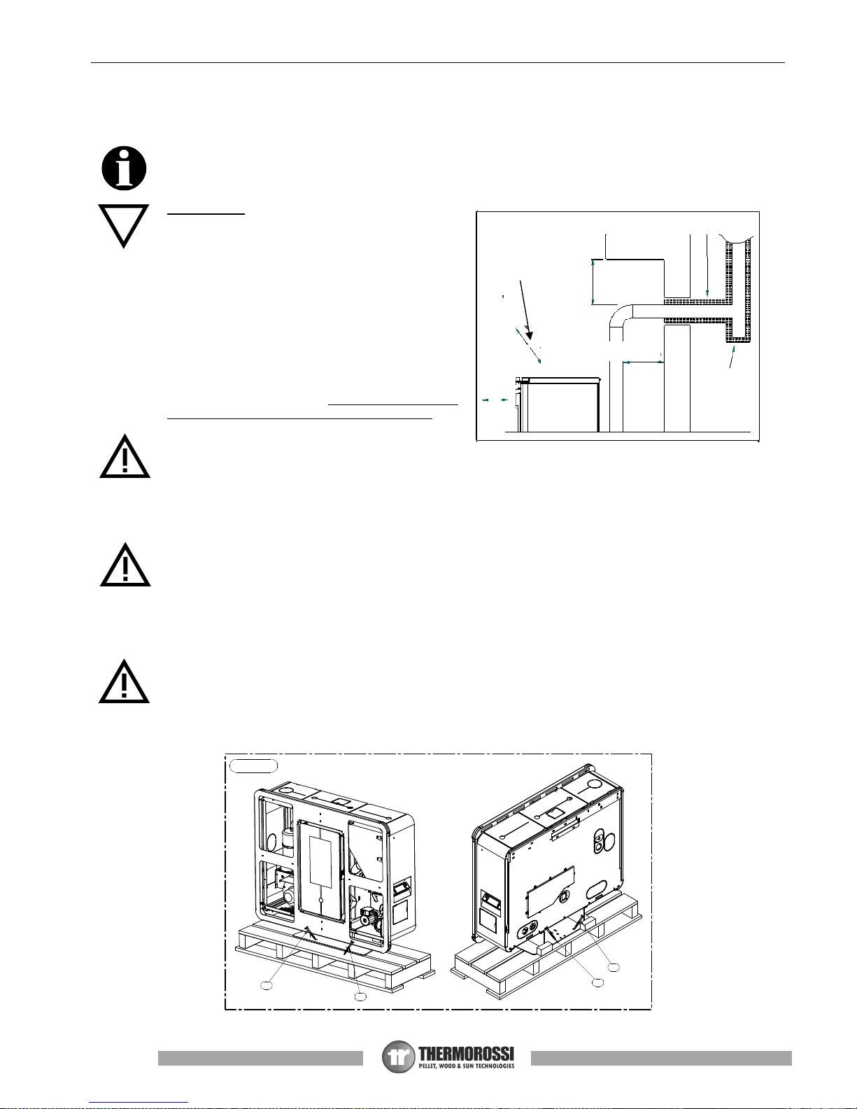
ATTENTION: The appliance must be installed in a
room with adequate ventilation. The appliance must be
positioned at a minimum safe distance from walls and
furnishings. If inflammable items are positioned near
the appliance (matchboarding, furniture, curtains, wall
hangings, sofas, etc...), this gap must be increased
considerably. The recommended minimum distances
are illustrated in the drawing below on the right. If the
flooring is made of wood or any other combustible
material, it is recommended to install a fireproof floor
protector plate between the appliance and the floor.
Installation in the vicinity of heat-sensitive materials is
only permitted if suitable insulating and fireproof
protection is placed between the object and the
appliance (ref. Uni 10683). Failure to observe this
instruction will immediately invalidate the warranty.
The installer must issue a certificate of conformity for
the installation which includes the design plans and the
following documents:
a) Report containing the type of materials utilised.
b) Project as defined in Article 5 of Ministerial Decree n° 37 22 January 2008.
d) References to existing partial or previous declarations of conformity (e.g. electrical wiring).
e) Copy of the certificate of recognition of the professional technical qualifications.
These documents must, by law, be kept together with the use and maintenance booklet. The customer is responsible
for verifying, directly or indirectly, that the installation has been carried out to perfection in accordance with relevant
regulations in force. Do not install the appliance in unsuitable rooms such as bedrooms, bathrooms, garages and/or
lock-ups. It is forbidden to place the appliance in environments with an explosive atmosphere.
ATTENTION, the stove is not simply a household appliance: if the instructions set out in this booklet are not followed and/or if
installation of the appliance is not executed perfectly and/or the provisions in force are not strictly complied with, dangerous
conditions could arise for both objects and persons. It is the user’s responsibility to verify the presence, in the room, of a vent
necessary for supplying oxygen to the generator.
The installer must provide the final user with verbal instructions on the correct use of the appliance when the
appliance is set at work for the first time.
4.2 UNPACKING THE APPLIANCE
To unpack the appliance undo the screws C that fasten the base of the appliance to the pallet (Figure 1).
C
C
C
C
Figura 1
HEAT INSULATING MATERIAL
Inspectable Tee
element
if the material is combustible
200 mm if the material is
combustible
200 mm if the
material is
combustible
Page 14

Page
14
Installation, use and maintenance guide
SlimQuadro Idra 14
4.3 GLUING THE GLASS PANES TO THE FRONT
PANEL
After unpacking the glass panes of the casing,
disassemble the front panel as described below.
Prior to beginning any operation, lay a soft sheet
on the floor where you can place the front panel
after removing it from the appliance, in order to
prevent damaging the floor or scratching the paint
on the panel.
• Undo screws A and slide out the left protective
panel B
• Undo screws C and slide out the right protective
panel D
• Undo the two screws E that fix the right side of
the front panel
• Undo the two screws F that fix the left side of the
front panel
• Remove the front panel by detaching it from the
body of the appliance.
• Lay the front panel on the sheet on the floor.
To glue the panes to the front panel, firstly apply silicone to the surface of the panel as illustrated in Figure 1. Attention: as
highlighted in Detail C, do not apply silicone to the areas where the corners of the glass cross over. If applied here the silicone
could leak out and ruin the look of the product.
Position each glass pane by placing it in an inclined position and using the locators A indicated in Figure 1. When the edges of the
glass abut the locators A, delicately place the entire surface of the pane with the applied silicone and exert uniform pressure with
your hands over the whole surface, while making sure that the pane remains aligned in position. Repeat this procedure for all the
glass panes.
After checking that the panes are aligned with each other and with the front panel secure them in position by applying strips of
paper tape along the edges.
Wait at least 24h for the silicone to cure before handling the front panel. If the room temperature drops below 18°, wait at least 48
hours for the silicone to cure completely.
ATTENTION: Use mono-component acetic-reticulation silicone suitable for high temperatures (min. 200°C, max.
300°C) .
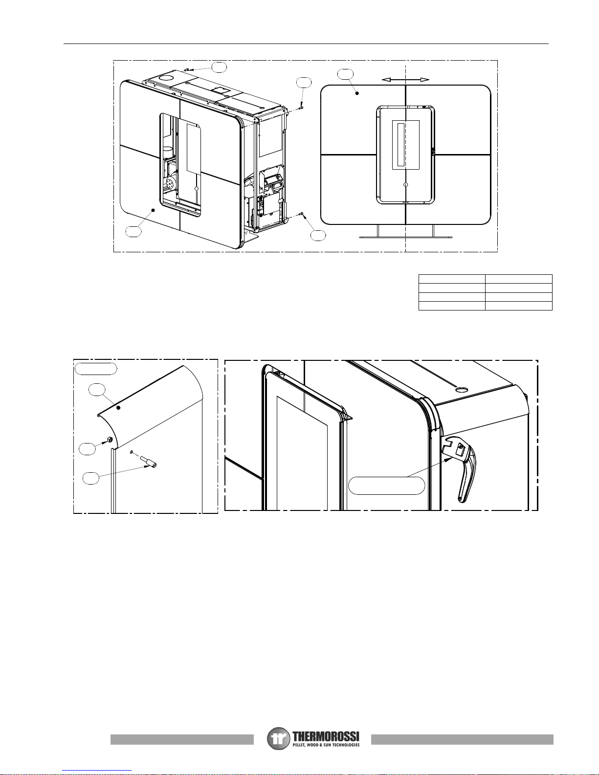
4.4 REMOUNTING THE FRONT PANEL
Once the appliance has been installed, the next step is to remount the front panel. Re-attach the front panel G to the body of the
appliance and lightly screw in the screws E (do not tighten). After checking that the front panel is aligned with the door (see the
alignment line in the drawing below) tighten the screws E. Complete the assembly of the heater.
Legenda
Key
Figura Figure
S
I
L
I
C
O
N
E
A
L
T
A
T
E
M
P
E
R
A
T
U
R
A
C
C
A
A
A
A
Figura 1
B
B
E
F
E
A
A
B
C
C
D
Page 15
Page
15
Installation, use and maintenance guide
SlimQuadro Idra 14
4.5 HANDLE
Your appliance is supplied with a handle for opening and closing the firebox door to facilitate
cleaning (see paragraph 8). The handle is also designed to be used for regulating the channelling flow rate. When not in use, the
handle can be stowed on the side of the appliance if the hook provided is attached to the stove. (see Figure 4).
4.6 WALL MOUNT INSTALLATION
The appliance is supplied standard with a wall mount bracket.
To install the appliance on the wall firstly remove the left, right and front panels (see instructions in paragraph 4.3).
Remove the bracket A by undoing the two screws B which can be accessed by releasing the central cover of the compartment C.
For instructions on how to fasten the bracket to the wall refer to the drawing in Figure 8.
ALLINEAMENTO
E
G
G
E
E
Figura 4
1
3
2
MANIGLIA
Legenda
Key
Figura Figure
MANIGLIA HANDLE
ALLINEAMENTO ALIGNMENT
Page 16
Page
16
Installation, use and maintenance guide
SlimQuadro Idra 14
Legenda
Key
Figura Figure
Vano Compartment
Viti Screws
Staffa Bracket
DETTAGLIO DETAIL
MANDATA IMPIANTO PLANT DELIVERY
USCITA FUMI SMOKE OUTLET
RITORNO IMPIANTO PLANT RETURN
CARICO SCARICO IMPIANTO SYSTEM INLET OUTLET
A
DETTAGLIO D
Figura 7
Staffa
A
Viti
B
Vano
C
B
DETTAGLIO C
401
552
452
47295
256 190
145
596
405
475
414
190
858
1037
MANDATA
IMPIANTO
USCITA
FUMI
RITORNO
IMPIANTO
CARICO
SCARICO
IMPIANTO
O
6
0
240 - Presa aria
Page 17
Page
17
Installation, use and maintenance guide
SlimQuadro Idra 14
1
6
K
4
2
2
W
X
Y
3
5 – HYDRAULIC CONNECTION
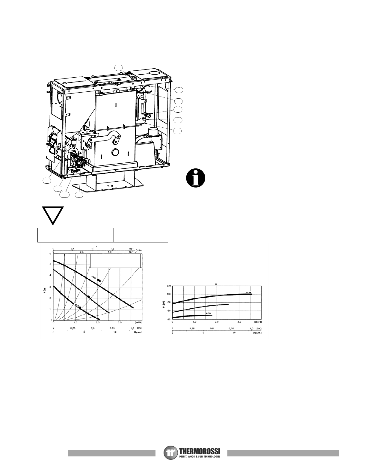
5.1 HYDRAULIC DIAGRAM
1 System circulating pump
2 Automatic relief valve
3 Sensor PTC appliance’s body
4 Thermostat bulb 100°C reset
6 Closed expansion tank
X Heating plant return
K Plant delivery
Y Safety valve 3 bar
W Plant drain and make-up gate valve
ATTENTION: FOR THE DELIVERY, RETURN, MAKEUP AND DISCHARGE CONNECTIONS USE FLEXIBLE
TUBES HAVING A LENGTH OF AT LEAST 70 CM TO
FACILITATE MOVING THE APPLIANCE FOR
MAINTENANCE.
ATTENTION: A CONNECTION MUST BE MADE BETWEEN THE SAFETY VALVE AND THE OUTLET TO
PREVENT DAMAGING MATERIALS SURROUNDING THE APPLIANCE WHEN THE VALVE IS ACTIVATED.
ATTENTION: To avoid continual startups and shut offs, the size of the plant must be such as to guarantee power
absorption that is not less than the power generated by the appliance running at minimum steady state power level.
Head loss with ∆t 20°C between
delivery and return - mbar
32.2 15.4
CHARACTERISTIC CURVES OF
SINGLE-PHASE PUMP
Page 18
Page
18
Installation, use and maintenance guide
SlimQuadro Idra 14
VNR
(z o n a c o n p iu ' a s so r b im en to )
Elettrova lvola s em p re ap e r t a
COLLETTORE
COLLETTORE
TA TA
VEC
TA
S
VM3VT
APPARECCHIO
VSP
A
R
A : andata impianto riscaldamento
R : ritorno impianto riscaldamento
S : saracinesca
VNR : valvola di non ritorno
VEC : vaso di espansione chiuso per protezione impianto
VM3VT : valvola miscelatrice 3 vie termostatica 55°c punto fisso
VSP : valvola saracinesca (da parzializzare in funzione delle
perdite
di carico dell'impianto
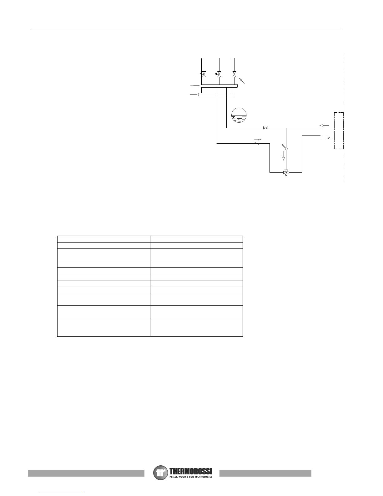
5.1.1 GUIDELINES FOR PLANTS WITH ZONE VALVES
Note: above 61°C, the generator pump is always
active as it is essential to dissipate the heat;
therefore the solenoid valve must be open for the
following reasons
:
• to prevent the generator from continually
starting up and shutting off caused by the
inevitable loss of heat to the header and/or due to
plant tubing.
• to prevent the generator from raising the water
temperature by just a few degrees each time it is
switched off then back on until it shuts down due
to exceeding the maximum threshold temperature
of 98°C (manually reset thermostat).
To adjust the ambient temperature in which the
valve opened, we recommend connecting the
room temperature thermostat to the
CHRONOTHERMOSTAT MODEM terminal (free
contact COM-NO see para. 7) that allows the
machine to be shut off via an external contact and
therefore also restarted.
This ensures that the generator only activates if
there is a real request for heat from the zone in which the chronothermostat is installed.
Several parallel-connected room temperature thermostats can be installed in the CHRONOTHERMOSTAT MODEM. This will
ensure that the zone requesting heat (contact closed) automatically activates the generator.
In the event of frequent startups and shut offs due to the heat produced by the generator not being absorbed, the manual reset
safety thermostat trips and blocks the generator.
N.B.: Use chronothermostats having at least 2°C hysterisis.
Legenda
Key
Collettore Header
Elettrovalvola sempre aperta
(zona con più assorbimento)
Solenoid valve always open
(zone with the most absorption)
Apparecchio Appliance
A: andata impianto riscaldamento A – heating plant delivery
R: ritorno impianto riscaldamento R – heating plant return
S: saracinesca S – gate valve
VNR: valvola di non ritorno VNR – nonreturn valve
VEC: vaso di espansione chiuso per
protezione impianto
VEC: closed expansion tank for
plant protection
VM3VT: valvola miscelatrice 3 vie
termostatica 55°C punto fisso
VM3VT: Three-way thermostatic
mixing valve 55°C, fixed point
VSP: valvola saracinesca (da
parzializzare in funzione delle
perdite di carico dell’impianto)
VSP: Gate valve (throttle according
to pressure drop in the system)
Page 19

Page
19
Installation, use and maintenance guide
SlimQuadro Idra 14
5.2 HYDRAULIC DIAGRAM WITH HEATING ONLY
Legenda
Key
Scarico Outlet
APPARECCHIO APPLIANCE
A: andata impianto riscaldamento A – heating plant delivery
R: ritorno impianto riscaldamento R – heating plant return
S: saracinesca S – gate valve
VNR: valvola di non ritorno VNR – nonreturn valve
VEC: vaso di espansione chiuso per protezione
impianto
VEC: closed expansion tank for plant protection
VR: valvola riduttrice di pressione VR: pressure reducing valve
VM3VT: valvola miscelatrice termostatica punto
fisso 55°C
VM3VT: thermostatic mixing valve, fixed point 55°C
VSP: valvola saracinesca (da parzializzare in
funzione delle perdite di carico dell’impianto)
VSP: Gate valve (throttle according to pressure
drop in the system)
Dall’acquedotto per reintegro From water mains for make-up
ATTENTION: it is mandatory to earth the generator. If this instruction is not observed serious damage, which
is not covered by warranty, will result to the body of the appliance. Have a skilled electrician check the
earthing. There must be no electric potential (Volt) between the generator earth and the plant’s real earth
(earth plate). To prevent electrochemical corrosion of the appliance body do not use galvanised pipes and
fittings. Other materials must be earthed with special earthing cables in order to obtain a unipotential
earthing system.
R
S
VNR
A
S
VEC
VM3 VT
per r e i n teg ro
Da ll 'a cq ue d otto
sca ric o
S
VR
VSP
APPARECCHIO
A
R
A : andata impianto riscaldamento
R : ritorno impianto riscaldamento
S : saracinesca
VNR : valvola di non ritorno
VEC : vaso di espansione chiuso per protezione impianto
VR : valvola riduttrice di pressione
VM3VT : valvola miscelatrice termostatica punto fisso
55°c.
VSP: valvola saracinesca (da parzializzare in funzione
delle perdite di carico dell'impianto)
Page 20

Page
20
Installation, use and maintenance guide
SlimQuadro Idra 14
5.3 EXAMPLE OF HYDRAULIC DIAGRAM WITH INTERSPACED BOILER COILS OR BOILER COILS
Legenda
Key
Scarico Outlet
APPARECCHIO APPLIANCE
Bollitore ad intercapedine o a serpentino Boiler tubes with interspacing or boiler coils
A: andata impianto riscaldamento A – heating plant delivery
R: ritorno impianto riscaldamento R – heating plant return
S: saracinesca S – gate valve
VNR: valvola di non ritorno VNR – nonreturn valve
VEC: vaso di espansione chiuso per protezione
impianto
VEC: closed expansion tank for plant protection
VR: valvola riduttrice di pressione VR: pressure reducing valve
VM3VT: valvola miscelatrice termostatica punto
fisso 55°C
VM3VT: thermostatic mixing valve, fixed point 55°C
VSP: valvola saracinesca (da parzializzare in
funzione delle perdite di carico dell’impianto)
VSP: Gate valve (throttle according to pressure
drop in the system)
Dall’acquedotto per reintegro From water mains for make-up
ATTENTION: The water temperature in the boiler tubes in this case is not adjustable and depends on the system's delivery
temperature, that is the temperature set in the generator. The boiler tubes can be installed on the water return circuit. It is
recommended to install a water softener in the domestic water system in order to maintain the boiler at its peak efficiency.
ATTENTION: it is mandatory to earth the generator. If this instruction is not observed serious damage, which
is not covered by warranty, will result to the body of the appliance. Have a skilled electrician check the
earthing. There must be no electric potential (Volt) between the generator earth and the plant’s real earth
(earth plate). To prevent electrochemical corrosion of the appliance body do not use galvanised pipes and
fittings. Other materials must be earthed with special earthing cables in order to obtain a unipotential
earthing system.
A : andata impianto riscaldamento
R : ritorno impianto riscaldamento
S : saracinesca
VNR : valvola di non ritorno
VEC : vaso di espansione chiuso per protezione impianto
VR : valvola riduttrice di pressione
VM3VT : valvola miscelatrice termostatica punto fisso 55°c
VSP: valvola saracinesca (da parzializzare in funzione
delle perdite di carico dell'impianto).
S
R
VNR
A
VEC
BOLLITORE AD
INTERCAPEDINE
S
S
O A SERPENTINO
per rein teg r o
Da ll' a c q u e d ott o
sca ric o
S
VR
VM3 VT
VSP
APPARECCHIO
A
R
Page 21

Page
21
Installation, use and maintenance guide
SlimQuadro Idra 14
5.4 EXAMPLE OF HYDRAULIC DIAGRAM WITH BOILER COILS AND HEATING SYSTEM
Legenda
Key
Contatto cronotermostato Chronothermostat contact
Impianto System
Contatto cronotermostato modem della caldaia Chronothermostat modem contact of the stove
SB ai pin 5 e 6 della morsettiera CN5 SB to pins 5 and 6 of the terminal block CN5
Alimentazione dalla morsettiera CN3 pin 5 (neutro), pin 7 (L1), pin 8
(L2)
Power supply from the terminal block CN3 pin 5 (neutral), pin 7 (L1),
pin 8 (L2)
Scarico Outlet
APPARECCHIO APPLIANCE
A: andata impianto riscaldamento A – heating plant delivery
R: ritorno impianto riscaldamento R – heating plant return
S: saracinesca S – gate valve
VNR: valvola di non ritorno VNR – nonreturn valve
VEC: vaso di espansione chiuso per protezione impianto VEC: closed expansion tank for plant protection
VSP: valvola saracinesca (da parzializzare in funzione delle perdite
di carico dell’impianto)
VSP: Gate valve (throttle according to pressure drop in the system)
SB: sonda acqua calda sanitaria SB: domestic hot water sensor
VR: valvola riduttrice di pressione VR: pressure reducing valve
VM3VT: valvola miscelatrice termostatica punto fisso 55°C VM3VT: thermostatic mixing valve, fixed point 55°C
VDEV3V: valvola deviatrice 3 vie alimentata in chiusura e anche in
apertura
VDEV3V: 3 way diverting valve powered at closure and also at
opening
Dall’acquedotto per reintegro From water mains for make-up
In order to guarantee correct absorption of the heat produced by the generator it is advisable to use a boiler tube with volume and
heat exchange capacity suitable for the power of the generator. The boiler tube must have a minimum capacity of 300l. In any case
the boiler tube must be capable of absorbing all the power that the generator is capable of delivering.
If this rule is not observed, the generator could raise the water temperature to such a point as to activate the safety limit thermostat
which stops the fuel from dropping into the burner and therefore forces the appliance to shut off.
The installer is required to install a valve that switches over to the system, powered by the stove’s control unit, which trips when the
boiler is thermally “satisfied ”. Consequently, the plant must be designed in such a way that the hot water produced by the generator
can reach the various rooms by acting on the zone valves.
ATTENTION: it is mandatory to earth the generator. If this instruction is not observed serious damage, which
is not covered by warranty, will result to the body of the appliance. Have a skilled electrician check the
earthing. There must be no electric potential (Volt) between the generator earth and the plant’s real earth
(earth plate). To prevent electrochemical corrosion of the appliance body do not use galvanised pipes and
fittings. Other materials must be earthed with special earthing cables in order to obtain a unipotential
earthing system.
S
R
S
VNR
S
VNR
S
A
VDEV3 V
VEC
VM3 VT
Co n t a t t o Cr o n o t e r m o s t a t o
Mo d e m d ella ca ld a ia
Co n t a t t o Cr o n oter m o st a t o
Im p i a n to
VSP
p er rein teg r o
Da l l' acq u ed otto
sca r i c o
S
VR
APPARECCHIO
A
R
A : andata impianto
riscaldamento
R : ritorno impianto riscaldamento
S : saracinesca
VNR : valvola di non ritorno
VEC : vaso di espansione chiuso per protezione
impianto
VSP : valvola saracinesca ( da parzializzare in
funzione
delle perdite di carico dell'impianto).
SB : sonda acqua calda sanitaria
VR : valvola riduttrice di pressione
VM3VT : valvola miscelatrice termostatica punto fisso 55°c.
VDEV3V : valvola deviatrice 3 vie alimentata in chiusura e anche in
apertura.
Alimentazione
dalla morsettiera CN3
pin 5 (neutro), pin 7 (L1) , pin 8 (L2)
SB ai pin 5 e 6 della
morsettiera CN5.
Page 22

Page
22
Installation, use and maintenance guide
SlimQuadro Idra 14
5.5 HYDRAULIC DIAGRAM WITH THERMOCELL (OR THERMOPUFFER) + ADDITIONAL THERMOPUFFER +
HIGH TEMPERATURE HEATING AND LOW TEMPERATURE HEATING.
Legenda
Key
Attenzione: chiudere tutti i fori non usati del puffer Note: close all the holes not used by the puffer
Radiatori Radiators
Riscaldamento pavimento Underfloor heating
Sonda PT 100 S1 ai pin 1 e 2 della morsettiera CN5 Temperature sensor PT 100 S1 to pins 1 and 2 of terminal block CN5
Sonda PT 100 S2 ai pin 3 e 4 della morsettiera CN5 Temperature sensor PT 100 S2 to pins 3 and 4 of terminal block CN5
Sonda PT 100 S2 (50°c – 55°c) Temperature sensor PT 100 S2 (50°C – 55°C)
Sonda PT 100 S1 (60°c – 65°c) Sensor PT 100 S1 (60°C – 65°C)
Tubi di collegamento accumuli Connection tubes to puffers
Thermopuffer aggiuntivo Additional Thermopuffer
Thermocell o Thermopuffer Thermocell or Thermopuffer
Apparecchio Appliance
A: andata impianto riscaldamento A – heating plant delivery
R: ritorno impianto riscaldamento R – heating plant return
S: saracinesca S – gate valve
VNR: valvola di non ritorno VNR – nonreturn valve
C: circolatore C: circulating pump
V3V: valvola a 3 vie V3V: three-way valve
V3VM: valvola 3 vie ad azionamento manuale V3VM: manual 3-way valve
VM3VT: valvola miscelatrice termostatica punto fisso 55°C VM3VT: thermostatic mixing valve, fixed point 55°C
VEC: Vaso di espansione chiuso per protezione impianto VEC: Closed expansion tank for plant protection
VSP: valvola saracinesca (da parzializzare in funzione
delle perdite di carico dell’impianto)
VSP: Gate valve (throttle according to pressure drop in the system)
ATTENTION: the preload pressure of the expansion tank must be greater than the plant pressure: for an expansion
tank preloaded to 2 bar the plant must be loaded to a pressure that does not exceed 1.5 bar.
ATTENTION: The Thermocell is only fitted with a connection to 230V - 50Hz power line; The settings of Sensor S1
and Sensor S2 must only be controlled by the appliance (See Par. 6.6) Connect the two sensors PT 100 (optional
code no. 60010695) to the terminals on the appliance’s "Sensor S1" and “Sensor S2" board. Sensor S2 must always
be positioned at the same height as the water delivery to the system.
ATTENTION: Sensor S1 must be set at a range of between 60°C and 65°C, sensor S2 must be set at a range of
between 50°C and 55°C. These settings are only approximate as the optimal setting is carried out by the Service
Centre on site during the initial testing of the stove, following the assessment of the system’s specific characteristics.
Attenzione : chiudere tutti i fori
non usati del puffer
Sonda PT100 S2
Sonda PT100 S1
non usati del puffer
Attenzione : chiudere tutti i fori
Riscaldamento pavimento
Radiatori
Thermopuffer aggiuntivo
Tubi di collegamento accumuli
Thermocell o Thermopuffer
(50°c - 55°c)
(60°c - 65°c)
Sonda PT 100 S1 ai pin 1 e 2
della morsettiera CN5
APPARECCHIO
A
R
Sonda PT 100 S2 ai pin 3 e 4
della morsettiera CN5
S
S
S
S
S
S
S
S
S
S
VSP
VM3 VT
VNR
VNR
VNR
VEC
V3 VM
V3 V
V3 V
C
C
A : andata impianto riscaldamento
R : ritorno impianto riscaldamento
S : saracinesca
VNR : valvola di non ritorno
VEC : vaso di espansione chiuso per protezione impianto
VSP : valvola saracinesca ( da parzializzare in funzione
delle perdite di carico dell'impianto).
C : circolatore
V3V : valvola 3 vie
V3VM : valvola 3 vie ad azionamento manuale
VM3VT : valvola miscelatrice termostatica punto fisso 55°c.
Page 23

Page
23
Installation, use and maintenance guide
SlimQuadro Idra 14
ATTENTION: it is mandatory to earth the generator. If this instruction is not observed serious damage, which
is not covered by warranty, will result to the body of the appliance. Have a skilled electrician check the
earthing. There must be no electric potential (Volt) between the generator earth and the plant’s real earth
(earth plate). To prevent electrochemical corrosion of the appliance body do not use galvanised pipes and
fittings. Other materials must be earthed with special earthing cables in order to obtain a unipotential
earthing system.
ATTENTION: Sensor S2 and sensor S1 must be connected to the dedicated clamps on the terminal block as indicated in the
diagram. To view the readings of Sensors S1 and S2 on the display it is necessary to activate the THERMOCONTROL function
(See. Para. 6.6).
5.6 INSTRUCTIONS FOR EXECUTING THE HYDRAULIC SYSTEM CLOSED EXPANSION TANK
To install the system with a closed expansion tank refer to the requirements laid down in EN 10412-2:2009 for appliances with
nominal heat output not exceeding 35 kW or in the Ministerial Decree Collection R edition 2009 for appliances with nominal heat
output exceeding 35kW.
The hydraulic system must be installed by qualified personnel who are familiar with the standards mentioned above and who have
the appropriate professional requirements to release the declaration of conformance in accordance with Ministerial Decree n° 37 of
22 January 2008.
The generator is already supplied with the following safety devices on board:
a) closed expansion tank for generator protection only*
b) ordinary safety valve 3 bar, not I.S.P.E.S.L. approved
c) an automatic reset temperature limiting device;
This is an automatic adjustment device that interrupts the fuel supply to the generator when the water reaches the
temperature setting. The system starts up again automatically when the water temperature drops below the preset value.
d) a manual reset temperature limiting safety device;
This is an automatic device that interrupts the fuel supply when the water reaches the maximum permissible temperature.
The fuel infeed will only restart when the water temperature drops below a preset value and after the device has been
reset manually.
e) circulation system.
The appliance is fitted with a circulating pump connected to the return pipes which is controlled directly by the
generator’s control board.
*
An additional closed expansion tank must be series-connected to the generator as protection for the system.
The nominal volume of the additional closed expansion tank must be sized in relation to the volume of expansion of the water
contained in the system. Thermorossi prescribes that the size of the additional closed expansion tank must be equal to 10% of the
water contained in the system.
The previous chapter does not replace the above standards to which it makes reference. The qualified installer must in
any case be fully aware of the above standards and their amending versions.
Page 24

Page
24
Installation, use and maintenance guide
SlimQuadro Idra 14
6 – USE OF THE APPLIANCE
The appliance, when operating, could be hot to the touch, particularly the door of the combustion chamber: take care
when handling the appliance components. Your appliance has obtained the CE marking and has been made to run for
at least one hour to check that it functions correctly. The product must not be used by children, by persons with
physical or mental impairments, by persons who are not familiar with the instructions for use and maintenance of the
product (the instructions are found in this use and maintenance booklet).
ATTENTION: Before each use make sure that the burner is clean.
ATTENTION: the door must always remain shut tight when the appliance is operating. It is strictly forbidden to open the
door while the appliance is in operation. While the appliance is in operation the smoke exhaust pipes can reach
extremely high temperatures: do not touch them! It is strictly prohibited to use any type of fuel (liquid, solid...) other than
pallet to light up the appliance: lighting must occur automatically as intended and described in this installation, use and
maintenance booklet; consequently, it is also strictly forbidden to feed pellets (or any other material) into the brazier. Do
not place non-heat resistant or inflammable or combustible objects in the vicinity of the appliance: keep them at a
suitable distance. Do not place wet clothing to dry on the appliance. When using a clothes horse, keep at a suitable
distance. It is strictly prohibited to disconnect the appliance from the electrical power mains during normal operation.
6.1 DESCRIPTION OF THE CONTROL PANEL
The control panel is managed by a microprocessor. The temperature detection system uses thermocouples. The large display
improves the appliance management by making read-outs and functions promptly available. The main feature of the panel is the allautomatic management of the appliance. The controls and the various displays are described below.
Flame button
Pressing this button when the appliance is off activates the
START
sequence (See Para. 6.10), sets the operating
power in the
WORK
mode (See Para. 6.10) or shuts off the appliance by activating the
OFF
sequence (See Para.
6.10).
Degrees Button
Press this button to set the target water temperature; the setting range is between 65 °C and 73 °C. This value is
displayed on the left side of the display next to the thermometer symbol.
Attention: the target temperature is only considered if the appliance is in AUTO mode (See Para. 6.10).
Scroll buttons (only in the Menu)
Press MINUS key to lower the value. Press PLUS key to raise the preset value.
Clock button
Press this button to activate / deactivate the programming. (See para. 6.4),
Menu button
Press this button to access the main menu. You can scroll the setting screens shown below, which will be described in
detail in the following paragraphs. To access the functions of each subwindow wait a few seconds.
DATE/TIME
This button is used to set the day of the week, the hour and minutes. (See para. 6.3)
CHRONO
This button is used to set the programmed on and off sequences. (See para. 6.4)
LEVEL
Is used to change the rotation speed of the smoke suction unit. (See para. 6.5)
THERMOCONTROL
Enables you to activate or deactivate the control of a puffer (if installed).
This screen only appears if the two optional sensors are connected to the appliance. (See para. 6.6)
ACS SUMMER
Enables you to activate or deactivate the dedicated control of a boiler (if installed) that produces
domestic hot water, thereby cutting off the system.
This screen only appears if the
optional sensor is connected to the appliance. (See para. 6.7)
T.AMBIENT
Enables you to control the ON/OFF cycles of the appliance according to the desired room temperature.
This screen only appears if the optional sensor is connected to the appliance (See para. 6.8)
Page 25

Page
25
Installation, use and maintenance guide
SlimQuadro Idra 14
THERMO ACS
Enables you to activate control of a boiler (if installed) for domestic hot water assigning absolute priority
to the boiler requirements before replenishing the system.
This screen only appears if the optional sensor is connected to the appliance (See para. 6.9)
Display
The following information can appear on the display:
The appliance is in the OFF stage (See para. 6.9).
1° MANUAL OPERATING POWER
2° MANUAL OPERATING POWER
3° MANUAL OPERATING POWER
4° MANUAL OPERATING POWER
5° MANUAL OPERATING POWER
In this mode the user can choose to run the appliance from the minimum power (therefore with the minimum pellet consumption) to
the maximum power (therefore with the maximum pellet consumption). In this case the appliance always runs at the set power
without any modulation in accordance with the target temperature.
AUTOMATIC LEVEL
The appliance modulates the the operating power automatically based on the target temperature set by the user. (See para. 6.10),
Indicates the temperature of the domestic hot water boiler, if the optional sensor is connected. (See para. 6.7 or 6.9)
Indicates the temperature of Sensor S1 for control of a puffer, if the optional sensor is connected. (See Para. 6.6)
Indicates the temperature of Sensor S2 for control of a puffer, if the optional sensor is connected. (See Para. 6.6)
Indicates that the circulation pump is activated when the water temperature in the boiler exceeds 61°C.
Indicates the boiler water temperature detected by the thermocouple.
The thermometer icon, on the left of the display, indicates the target temperature for the water in the boiler, which can be
adjusted by the user by means of the
Degrees Button.
Indicates that the appliance has been switched on by the contact of an external chronothermostat. (See para. 7.2)
Indicates that the appliance has been connected to a puffer which is requesting heat. (See para. 6.6)
Indicates that the ON/OFF programming set through CHRONO has been enabled. (See para. 6.4)
Indicates the room temperature detected by the thermocouple, if connected. (See para. 6.8)
The thermometer icon, on the right of the display, indicates the target room temperature set by the user if the optional
sensor is connected. (See para. 6.8)
Page 26

Page
26
Installation, use and maintenance guide
SlimQuadro Idra 14
6.2 DESCRIPTION OF THE POWER PANEL
The components of the power panel are described below:
1) Electrical power outlet 220V-240V 50Hz
2) Main switch 0/I.
3) Test light for pellet feed motor.
The light comes on simultaneously with the activation of the pellet
feed motor.
4) Cap for reset thermostat button.
If the reset thermostat overheats stop the pellet feeder. The appliance
must cool down before you can restart the appliance. After verifying
and eliminating the causes of the event, undo the protective cap and
press the button.
5) Safety fuse.
6.3 DATE/TIME: SETTING THE DATE AND TIME
The appliance must be energised and the I/0 switch in position “I".
The current date and time can be set using the DATE/TIME function.
To set the current time and date proceed as follows:
1) Press the
Menu Button
once to view the following screen:
2) After a few seconds the following screen will appear on the display:
3) Now press the
Scroll Buttons
to change the day of the week; each number corresponds to one day of the week (e.g. 1
corresponds to Monday, 2 corresponds to Tuesday, etc...). To confirm the selected day of the week press the
Degrees Button
.
Once confirmed, the selector shifts to the hour section while the selected day of the week remains framed:
4) Press the
Scroll Buttons
to change the hour. Once you have set the hour confirm the value by pressing the
Degrees Button.
Once confirmed, the selector shifts to the minutes section. Press the
Scroll Buttons
to set the minutes. To confirm press the
Degrees Button
.
Once confirmed, the date and time setting screen closes automatically and the initial screen returns to the display.
If you confirm the wrong value simply press the
Menu Button
several times to exit the box until the initial screen will appear, and
repeat the procedure described above.
6.4 CHRONO: ON/OFF PROGRAMMING
The appliance must be energised and the I/0 switch in position “I".
The CHRONO function allows you to set the weekly program by setting up to 3 on-off cycles at different times for every day from
Monday through to Sunday.
To set a program follow the procedure described below:
1) Press the
Menu Button
twice quickly to view the following screen:
After a few seconds the following screen will appear on the display:
2) Press the
Scroll Buttons
to select the day of the week on which you want to set the program. Each number corresponds to one
day of the week (e.g. 1 corresponds to Monday, 2 corresponds to Tuesday, etc...). To confirm the selected day of the week for
the programming press the
Degrees Button
. The following screen will appear:
Legenda
Key
RIARMO RESET
SPIA MOTORIDUTTORE RATIO MOTOR
INDICATOR
3
4
2
1
5
Page 27

Page
27
Installation, use and maintenance guide
SlimQuadro Idra 14
3) Now press the
Scroll Buttons
to select the hour at which you wish the appliance to start up automatically (ON1). Once the hour
is set confirm the value by pressing the
Degrees Button.
When scrolling the ON1 values the OFF1 values will scroll as well; this
is to avoid setting a shut off time that is earlier than the start up time.
Once confirmed, the selector shifts to the minute section of ON1. Press the
Scroll Buttons
to set the minutes for the first start
up. Confirm by pressing the
Degrees Button
.
4) Now press the
Scroll Buttons
to select the hour at which you wish the appliance to shut off automatically (OFF1). Once the
hour has been set, confirm the value by pressing the
Degrees Button.
Once confirmed, the selector shifts to the minute section of OFF1. Press the
Scroll Buttons
to set the minutes for the first shut
off. Confirm by pressing the
Degrees Button
.
At this point the first ON/OFF cycle for the selected day has been set.
The following screen will appear:
At this point if no further programming is required for that day go to point 5-A.
If, on the other hand, you wish to program a second ON/OFF cycle for that day go to point 5-B.
5-A) Press the
Menu Button
to exit the screen, in order to enable you to program the times for the ON/OFF cycles for the other
days of the week. In this case repeat the instructions from point 2 up to this paragraph.
5-B) Press the
Scroll Buttons
to select the hour at which you wish the appliance to start up automatically for the second time
(ON2). The start up time will be that set before OFF1; this is to avoid setting a second start up time that is earlier than the
preceeding shut off time. Once the hour is set confirm the value by pressing the
Degrees Button.
When scrolling the ON2
values the OFF2 values will scroll as well; this is to avoid setting a shut off time that is earlier than the start up time.
Once confirmed, the selector shifts to the minute section of ON2. Press the
Scroll Buttons
to set the minutes for the second
start up. Confirm by pressing the
Degrees Button
.
Now press the
Scroll Buttons
to select the hour at which you wish the appliance to shut off automatically (OFF2). Once the
hour has been set, confirm the value by pressing the
Degrees Button.
Once confirmed, the selector shifts to the minute section of OFF2. Press the
Scroll Buttons
to set the minutes for the
second shut off. Confirm by pressing the
Degrees Button
At this point the second ON/OFF cycle for the selected day has been set.
The following screen will appear:
At this point if no further programming is required for that day go to point 6-A.
If, on the other hand, you wish to program a third ON/OFF cycle for that day go to point 6-B.
6-A) Press the
Menu Button
to exit the screen, in order to enable you to program the times for the ON/OFF cycles for the other
days of the week. In this case repeat the instructions from point 2 up to this paragraph.
6-B) Press the
Scroll Buttons
to select the hour at which you wish the appliance to start up automatically for the third time (ON3).
The start up time will be that set before OFF2; this is to avoid setting a third start up time that is earlier than the preceeding
shut off time. Once you have set the hour confirm the value by pressing the
Degrees Button.
When scrolling the ON3
values the OFF3 values will scroll as well; this is to avoid setting a shut off time that is earlier than the start up time..
Once confirmed, the selector shifts to the minute section of ON3. Press the
Scroll Buttons
to set the minutes for the third
start up. Confirm by pressing the
Degrees Button
.
Now press the
Scroll Buttons
to select the hour at which you wish the appliance to shut off automatically (OFF3). Once the
hour has been set, confirm the value by pressing the
Degrees Button.
Once confirmed, the selector shifts to the minute section of OFF3. Press the
Scroll Buttons
to set the minutes for the third
shut off. Confirm by pressing the
Degrees Button.
At this point the third and final ON/OFF cycle for the selected day has been set.
Alternatively, if you wish to copy the exact same programming for the ON/OFF cycles set for a particular day to the next day simply
press the
Flame button
.
For example: if I want to copy all the programmed ON/OFF cycles set for Monday to Tuesday the following screen will appear:
Press the
Flame button
once again to copy all the cycles programmed for Tuesday to Wednesday. The following screen will
appear:
Page 28

Page
28
Installation, use and maintenance guide
SlimQuadro Idra 14
Using the same logic we can copy the programmed cycles to the other days.
7) To conclude the programming operations simply press the
Menu Button
several times to exit the box until the initial screen will
appear.
ATTENTION: The appliance ignores any ON or OFF command programmed with a value of 00:00
.
Consequently if you do not wish to use an ON or OFF time setting simply set a value of
00:00
. The appliance ignores
any ON or OFF command if the shut off time is set the same as or before the start up time.
ATTENTION:
In the event of a programmed cycle on always ensure that the brazier is clean. Failure to clean the brazier can reduce
and/or affect the life of the spark plug as it would be subjected to high temperatures due to poor cooling. It is
recommended to set ON/OFF cycles times lasting no less than 2 hours, in order to save energy and for the proper
operation of the appliance.
.
Enabling the programmed cycles:
Back in the initial screen, to enable the appliance to carry out the ON/OFF cycles as programmed it is necessary to press the
Clock
Button
.
The image of a clock will appear on the main screen:
The programmed cycles are now enabled.
When the programmed cycles are enabled (a clock symbol appears on the display) it will not be possible to
use an additional chronothermostat (see Para. 7.2). The appliance will strictly follow the programmed ON/OFF
times. No request for heat by the system, a puffer or a domestic hot water boiler will be considered by the
appliance if it is outside the programmed time interval.
Disabling the programmed cycles:
To disable the appliance from carrying out the programmed ON/OFF cycles press the
Clock Button
once again.
On the display the clock symbol will disappear. This operation disables the weekly program that has been set by the user but does
not delete or reset the times.
Resetting the programmed cycles:
Moreover, it is possible to reset, in other words delete, all the programmed cycles entered by the user by holding down the
Clock
Button
in the initial screen for approx. five seconds.
The words
CLEAR TIMERS
will appear momentarily on the screen.
Do not release the button until the text CLEARED appears on the screen. Only the appearance of the words CLEARED
signal that the previously entered programmed cycles have been deleted. When the programmed cycles are active the
operating level at start up, that is the combustion power, will be the same level set before the last time the machine was
shut off: that is, only if it was a programmed shut off, not if the machine was shut off by means of a manual action.
Manual shut down can only be carried out with the programming disabled. If after a manual shut off the programmed
cycle re-enables, at the next programmed start up the appliance will be on the 1st combustion power level.
Page 29

Page
29
Installation, use and maintenance guide
SlimQuadro Idra 14
When is it important to use the CHRONO function?
In systems configured like the diagram on the right, where the appliance is connected
directly to the system, without the use of external chronothermostats. In this case it is
necessary to set the hour programs to prevent the appliance from being stressed by
uncontrolled ON and OFF cycles. In addition we recommend using the generator in AUTO
mode to activate the automatic modulation based on the target temperature setting.
If the dwelling is fitted with zone valves, with this type of installation, it is mandatory to
deactivate the valves by opening them completely.
Consequently the dissipation of heat, at least equal to or greater than the quantity of heat
generated by the appliance and transmitted to the water when running at the minimum
power level must be guaranteed at all times.
6.5 LEVEL: OPERATING LEVEL SETTING
The appliance must be energised and the I/0 switch in position “I".
Your appliance is delivered with an excellent program installed that favours combustion efficiency; the program is called
LEVEL 1
.
However, if you are using pellets with a higher than normal incidence of residues after combustion in the brazier, it is possible to
select alternative levels:
LEVEL 2
is an operating program that accelerates the speed of the smoke suction unit in proportion to all the combustion
power levels. This level must be set when the user notices a weak, high and very dark flame. Attention: this
modification does not authorise the use of below-standard pellets, or no vacuum in the flue outlet.
If using loosely compressed pellets, you could select:
LEVEL 0
: is an operating program that decelerates the speed of the smoke suction unit when using loosely compressed
pellets and/or when the flue outlet has a very high vacuum, over 2 mm water column (20 Pascal).
The pellet consumption value remains unchanged regardless of the selected operating level. These variations will only change the
rotation of the smoke suction unit in the WORK stage (see Para. 6.10), all the other stages will not undergo any changes.
Select the required Level by acting as follows:
1) Press the
Menu Button
three times quickly and the following box will appear:
After a few seconds the following screen will appear on the display:
2) To change the operating level, hold down a
Scroll Button
while simultaneously pressing the other
Scroll Button.
To set the desired level simply press the
Menu Button
several times until the initial screen will appear on the display.
The level selection can be made with the appliance
OFF
or ON. If the change is made while the appliance is running
the difference in the flame will be apparent. It is mandatory to pay particular care when selecting the most appropriate
operating cycle for your installation. After the selection of the operating cycle a thorough cleaning of the brazier is
mandatory.
6.6 THERMOCONTROL: CONTROLLING A PUFFER
The appliance must be energised and the I/0 switch in position “I".
This function enables you to control the operating temperature of a stratification puffer through the use of two sensors PT 100
(optional) connected to the respective terminal blocks on the electronic board (See para. 11).
ATTENTION:
If one or both optional sensors are not connected to the appliance or are interrupted, it will not be possible to view
and therefore activate the THERMOCONTROL function.
When this function is activated the appliance automatically controls the ON/OFF cycles based on the activation temperatures set by
the user.
The puffer must have an appropriate capacity. We recommend a capacity ranging between a minimum of 20 dm3 to a
maximum of 50 dm3 for every kW of maximum power supplied to the water by the appliance.
The THERMOCONTROL function can be activated in the following way:
1) Quickly press the
Menu Button
until the following screen appears:
Page 30

Page
30
Installation, use and maintenance guide
SlimQuadro Idra 14
After a few seconds the following screen will appear on the display:
2) Press one of the two
Scroll Buttons
and the following screen will appear (Select ON to activate).
3) Confirm the selection by pressing the
Degrees Button
and the following screen will appear:
4) Press the
Scroll Buttons
to set the activation temperature for Sensor S2. Sensor S2 is installed in the top part of the puffer
and it commands the appliance to start up as it is exhausting the available heat inside it. The setting range is between 40 °C
and 65 °C.
5) Confirm the selection by pressing the
Degrees Button
and the following screen will appear.
6) Press the
Scroll Buttons
to set the activation temperature for Sensor S1. Sensor S1 is installed in the lower part of the puffer
and it commands the appliance to shut off as the puffer is satisfied. The setting range is between 60 °C and 70 °C.
The settable temperature will in any case always exceed, by at least 4°C,the temperature setting for S2.
7) Confirm the selection by pressing the
Degrees Button
then press the
Menu Button
several times to exit the screen, until the
initial screen appears.
At this point the appliance operating status will appear on the display.
To
disable
the THERMOCONTROL function simply repeat operations 1 and 2, but this time select the OFF command. The function
will be disabled immediately.
ATTENTION
: it is advisable to set the action temperature for sensors S1 and S2 as indicated in the hydraulic diagrams
in this manual. Pay special attention to the number of ON/OFF cycles that the appliance is subjected to with this
function. It is recommended not to exceed three ON/OFF cycles. If the startups are frequent and repeated it is possible
the the generator will fail to start and the following error message appear : “Failed start – Clean burner” (See Para. 10).
The appearance of this message is not attributable to a product defect but is caused by a brazier that requires cleaning
as described in this manual in chapter entitles: “Troubleshooting – Possible Causes – Solutions”.
ATTENTION
: By setting the THERMOCONTROL ON the appliance will only start up and shut off autonomously
according to the temperature settings of sensors S1 and S2.
ATTENTION: If the programmed time schedule is enabled (a clock symbol appears on the display) the appliance will
follow exclusively the preset ON and OFF times. No request for heat from the puffer will be considered by the appliance
outside the programmed time interval and the texts WAIT TIME or NO PROGRAM will appear on the display (See
Para. 6.10).
ATTENTION: If an external chronothermostat is connected to the appliance, the appliance will follow it exclusively. No
request for heat from the puffer will be considered by the appliance if the external chronothermostat does not give
consent and the text WAIT TIME appears on the display (See para. 6.10).
Page 31

Page
31
Installation, use and maintenance guide
SlimQuadro Idra 14
By setting
THERMOCONTROL ON
, when the puffer is requesting heat the temperatures detected by the sensors S1 and S2 and
the word PUF will appear on the display.
When is it important to use the THERMOCONTROL function?
In systems configured like the diagram on the right, where the appliance is connected
directly to a stratification puffer.
When you use this function the generator starts up automatically when the puffer is
running out of heat then switches off when it is satisfied. The use of a correctly-sized puffer
also enables the production of low temperature heat, such as for example for under floor
heating systems, which otherwise could not be controlled by a high temperature biomass
appliance.
6.7 ACS SUMMER: ACTIVATION OF THE BOILER TUBE CONTROL FROM A CHRONO COMMAND
The appliance must be energised and the I/0 switch in position “I".
This function enables you to manage the operating temperature of a boiler tube for the production of domestic hot water (ACS)
through the use of a sensor PT 100 (optional) connected to the terminal block on the electronic board (See para. 11).
ATTENTION:
If the optional sensor is not connected to the appliance or is interrupted, it will not be possible to view and therefore
activate this function.
When this function is activated the appliance automatically controls the ON/OFF cycles based on the set temperature of the boiler
tube, and ignores requests for heat from the system and the puffer, if installed. This function is particularly useful in summer when
only domestic hot water is required without having to supply the heating system.
When this function is activated the appliance operates only at automatic power (See para. 6.10.3).
The ACS SUMMER function can be activated in the following way:
1) Quickly press the
Menu Button
until the following screen appears:
After a few seconds the following screen will appear on the display:
2) Press one of the two
Scroll Buttons
and the following screen will appear (Select ON to activate).
3) Confirm the selection by pressing the
Degrees Button
and the following screen appears:
4) Press the
Scroll Buttons
to set the minimum activation temperature for the sensor. The sensor is installed in the central part of
the boiler and commands the appliance to start up as the boiler tube is exhausting the available heat. The setting range is from
45°C to 65°C.
5) Confirm the selection by pressing the
Degrees Button
and the following screen will appear.
6) Press the
Scroll Buttons
to set the maximum activation temperature for the sensor. The sensor commands the appliance to
shut off as the boiler tube is satisfied. The setting range is from 49°C to 75°C.
The settable temperature will in any case always exceed, by at least 4°C, the temperature setting for ACS T.MIN.
7) Confirm the selection by pressing the
Menu Button.
8) This function requires the setting of daily time bands within which the appliance manages the boiler tube. The Chrono
screen will appear so you can program the weekly schedule for managing the boiler tube:
Page 32

Page
32
Installation, use and maintenance guide
SlimQuadro Idra 14
ATTENTION: If an external chronothermostat is connected to the appliance, it is not necessary to program any operating time band
as the appliance will follow the cycles set in the external chronothermostat. Consequently simply press the
Menu Button
several
times to exit the screen, until the initial screen appears.
After a few seconds the following screen will appear on the display:
9) To program the daily ON/OFF cycles repeat all the instructions starting from point 2 in paragraph 6.
10) To conclude the programming simply press the
Menu Button
several times to exit the screen, until the initial screen
appears.
Now the operating status of the appliance appears on the screen, the shower symbol will appear and next to it the temperature
detected by the sensor.
.
To
deactivate
ACS SUMMER function simply repeat operations 1 and 2 in this paragraph, but this time select the OFF command.
The function will be disabled immediately.
ATTENTION:
If the optional sensor is not connected to the appliance or is interrupted, it will not be possible to activate this function.
ATTENTION
The boiler tube must have at least a 300 litre capacity.
Pay special attention to the number of ON/OFF cycles that the appliance is subjected to with this function. It is
recommended not to exceed three ON/OFF cycles.
ATTENTION: If the programmed time schedule is enabled (a clock symbol appears on the display) the appliance will
follow exclusively the preset ON and OFF times. No request for heat from the boiler tube will be considered by the
appliance outside the programmed time interval and the texts WAIT TIME or NO PROGRAM will appear on the display
(See Para. 6.10).
ATTENTION: If an external chronothermostat is connected to the appliance, the appliance will follow it exclusively. No
request for heat from the puffer will be considered by the appliance if the external chronothermostat does not give
consent and the text WAIT TIME appears on the display (See para. 6.10).
ATTENTION: When ACS SUMMER is set the appliance will start up and shut off autonomously and only according to
the temperature setting of the boiler tube and the actual temperature
detected.
When is it important to use the ACS SUMMER function?
In systems configured like the nearby diagram, where the appliance is connected
directly to a domestic hot water boiler tube and to the system.
Using this function the generator starts up automatically when the boiler tube is is
running out of heat and only in the programmed time bands.
Once the boiler tube is satisfied, the appliance does not supply heat to the system
and shuts OFF.
6.8 T.AMBIENT: CONTROLLING THE ROOM TEMPERATURE
The appliance must be energised and the I/0 switch in position “I".
This function enables you to control, through use of a sensor PT 100 (optional) to be connected to pins 1 and 2 of the terminal block
CN5 on the electronic board (see para. 11), the temperature of the room where the sensor will be placed.
ATTENTION:
If the optional sensor is not connected to the appliance or if it is interrupted, it will not be possible to view and
consequently activate the T.AMBIENT function.
When this function is activated the appliance will automatically control the ON/OFF cycles according to the temperature set by the
user.
The TAMBIENT function can be activated by proceeding as follows:
1) Quickly press the
Menu Button
until the following screen appears:
After a few seconds the following screen will appear on the display:
Page 33

Page
33
Installation, use and maintenance guide
SlimQuadro Idra 14
2) Press one of the two
Scroll Buttons
and the following screen will appear (Select ON to activate).
3) Press the
Menu Button
several times, to confirm and exit the screen, until the initial screen appears. .
When
TAMBIENT ON
is activated, a house symbol with the temperature detected by the sensor next to it will appear on the display
as well as, in the bottom right corner, a thermometer symbol with the target room temperature next to it, as illustrated here:
The target room temperature can be changed at any time from the initial screen by simply pressing the
Scroll Buttons
.
To
deactivate
the TAMBIENT function simply repeat operations 1 and 2 in this paragraph, but this time select the OFF command.
The function will be disabled immediately.
ATTENTION:
If the optional sensor is not connected to the appliance or if it is interrupted, it will not be possible to
activate this function.
Pay special attention to the number of ON/OFF cycles that the appliance is subjected to with this function. It is
recommended not to exceed three ON/OFF cycles. If the startups are frequent and repeated it is possible that the the
generator will fail to start and the following error message appear: “Failed start – Clean burner” (See Para. 10). The
appearance of this message is not attributable to a product defect but is caused by a brazier that requires cleaning as
described in this manual in chapter entitles: “Troubleshooting – Possible Causes – Solutions”.
ATTENTION: If the programmed time schedule is enabled (a clock symbol appears on the display) the appliance will
follow exclusively the preset ON and OFF times. No request for heat from the environment will be considered by the
appliance outside the programmed time interval and the texts WAIT TIME or NO PROGRAM will appear on the display
(See Para. 6.10).
ATTENTION: If an external chronothermostat is connected to the appliance, the appliance will follow it exclusively. No
request for heat from the room will be considered by the appliance if the external chronothermostat does not give
consent and the text WAIT TIME appears on the display (See Para. 6.10).
ATTENTION: The appliance controls the room temperature sensor with a 2°C hysteresis, so if for example the user
sets a target temperature of 22°C when it reaches this temperature the appliance takes its power to the minimum, then
switches off when the temperature reaches 24°C. It will only restart when the temperature drops below 20°C at the
power previously set by the user.
ATTENTION: Do not place the room temperature sensor near any heat or cooling sources that could at any time affect
the temperature detected by the sensor.
When is it important to use the TAMBIENT function?
In systems configured like the nearby diagram, where the appliance is connected
directly to the system.
In this case the room temperature sensor controls the activation of the ON/OFF cycle
for the appliance according to the set temperature.
If the dwelling is fitted with zone valves, with this type of installation, it is mandatory to
deactivate the valves by opening them completely.
Consequently the dissipation of heat, at least equal to or greater than the minimum
power output to the water in the appliance, must be guaranteed at all times.
6.9 THERMO ACS: CONTROLLING A CONFIGURED BOILER TUBE IN A SYSTEM
The appliance must be energised and the main switch in position [I] .
This function enables control of the operating temperature of a boiler tube for the production of domestic hot water (ACS) through
the use of a sensor PT 100 (optional) connected to the appropriate terminal block (see Para. 11).
When this function is activated the appliance automatically controls the diverting valve to give priority to the domestic hot water.
Once the boiler tube is satisfied, the appliance switches the diverting valve to the system or the puffer (if installed) if they require
heat.
Page 34

Page
34
Installation, use and maintenance guide
SlimQuadro Idra 14
ATTENTION:
If the optional sensor is not connected to the appliance or if it is interrupted, it will not be possible to view and
consequently activate the THERMO ACS function.
The THERMO ACS function can be activated by proceeding as follows:
1) Quickly press the
Menu Button
until the following screen appears:
:
After a few seconds the following screen will appear on the display:
2) Press one of the two
Scroll Buttons
and the following screen will appear (Select ON to activate).
3) Confirm the selection by pressing the
Degrees Button
and the following screen will appear:
4) Press the
Scroll Buttons
to set the minimum activation temperature for the sensor. The sensor is installed in the central
part of the boiler tube and commands the appliance to start the boiler if it is off. On the other hand if the appliance is
operating, it commands the diverting valve as the available heat inside it is coming to an end. The setting range is from
45°C to 65°C.
5) Confirm the selection by pressing the
Degrees Button
and the following screen will appear.
6) Press the
Scroll Buttons
to set the maximum activation temperature for the sensor. The sensor commands the appliance
to shut off if it is ON, whereas if the appliance is operating, it commands the diverting valve as the boiler tube is satisfied.
The setting range is from 49°C to 75°C.
Attention: The maximum temperature will always exceed, by at least 4°C, the minimum set temperature.
7) Confirm the selection by pressing the Degrees Button followed by the Menu Button.
At this point the appliance operating status will appear on the display.
To
disable
the THERMO ACS unction simply repeat operations 1 and 2 selecting the OFF command. The function will be disabled
immediately.
When this function is activated the appliance operates at the automatic power (See para. 6.10.3) when the domestic hot water
boiler tube is requesting heat, it then reverts back to the power selected by the user when the boiler is satisfied.
ATTENTION:
The boiler tube must have at least a 300 litre capacity.
If the optional sensor is not connected to the appliance or if it is interrupted, it will not be possible to activate this
function.
Pay special attention to the number of ON/OFF cycles that the appliance is subjected to with this function. It is
recommended not to exceed three ON/OFF cycles. If the startups are frequent and repeated it is possible that the the
generator will fail to start and the following error message appear: “Failed start – Clean burner” (See Para. 10). The
appearance of this message is not attributable to a product defect but is caused by a brazier that requires cleaning as
described in this manual in chapter entitles: “Troubleshooting – Possible Causes – Solutions”.
ATTENTION: If the programmed time schedule is enabled (a clock symbol appears on the display) the appliance will
follow exclusively the preset ON and OFF times. No request for heat from the boiler tube or system will be considered
by the appliance outside the programmed time interval and the texts WAIT TIME or NO PROGRAM will appear on the
display (See para. 6.10).
ATTENTION: If an external chronothermostat is connected to the appliance, the appliance will follow it exclusively. No
request for heat from the boiler tube or system will be considered by the appliance appliance if the external
chronothermostat does not give consent and the text WAIT TIME appears on the display (See para. 6.10).
When
ACS ON
is activated the shower symbol with the temperature detected by the sensor will appear on the display. The shower
symbol will flash if the boiler tube requesting heat, whereas it will remain steady if the boiler tube is satisfied.
Page 35

Page
35
Installation, use and maintenance guide
SlimQuadro Idra 14
When is it important to use the THERMO ACS function?
In systems configured like the nearby diagram, where the appliance is connected
directly to a domestic hot water boiler tube and to the system.
When using this function the generator starts up automatically when the boiler tube is
running out of heat. Once the boiler tube is satisfied, the appliance commutes the 3way valve to provide heat to the system.
We recommend installing a chronothermostat to prevent the appliance from being
stressed by uncontrolled ON and OFF cycles (See. para. 7.2)
When is it important to use the THERMO ACS function together with the
THERMOCONTROL function?
In systems configured like the nearby diagram, where the appliance is installed in a
system fitted with both a boiler tube and a puffer.
Activate the THERMOCONTROL function to control the puffer and the THERMO
ACS function to control the boiler tube. With this logic the appliance controls the
ON/OFF cycles automatically according to the heat requests from both the puffer and
the boiler tube. Precedence is always given to the boiler tube, and once satisfied, the
appliance switches the 3-way valve and diverts the heat to the puffer and when it is
satisfied it switches OFF.
When is it important to use the THERMO ACS function together with the
TAMBIENT function?
In systems configured like the nearby diagram, where the appliance is connected
directly to a domestic hot water boiler tube and to the system.
When using this function the generator starts up automatically when the boiler
tube is running out of heat.
Once the boiler tube is satisfied, the appliance gives consent for the 3-way valve
to switch over in order to supply the system with heat. When the room
temperature is satisfied the appliance turns to the OFF position, and waits for the
next request for heat from the boiler tube or the room.
6.10 OPERATION OF THE GENERATOR
6.10.1 DESCRIPTION OF THE OPERATING STAGES
START:
has a duration of approx. 20 minutes, during this phase the appliance is programmed to light the flame. The appliance will
not accept power variations in the firebox. If the appliance does not start up correctly it could be due to one of the following factors:
cleanliness of the generator, smoke exhaust particularly cold, sudden surges and drops in the electric power supply, fuel is too
moist or does not comply with the specifications (see para. 3.2) .
Legenda
Key
Temperatura acqua
generatore (°C)
Generator water
temperature (°C)
Avvio Start
Lavoro Running
Off Off
Tempo (minuti) Time (minutes)
WORK
: the duration depends on the ability of the system to receive
heat. The generator's operating status is displayed. During this stage the brazier cleaning mechanism “Pellet Power”, that is, the
device installed inside the brazier, moves in timed mode.
OFF:
has a duration of approx. 25 minutes. In this phase the appliance is switched off until a new "on" phase is initiated. The aim is
to make the pellet embers in the brazier die out. A few seconds aftet the activation of the OFF cycle the brazier cleaning
mechanism “Pellet Power”, that is, the device installed inside the brazier, moves in continuous mode. After approx. 25 minutes the
appliance goes to standby and the brazier cleaning mechanism “Pellet Power” stops.
ATTENTION:
It is recommended to verify at least once a month that when the appliance is in OFF mode in the time
interval specified above, the brazier cleaning mechanism “Pellet Power” operates in continuous mode to clean the
brazier.
STOP:
If the temperature of the appliance exceeds the 80°C threshold, the momentary shut off, identified as STOP, is activated.
ATTENTION: The STOP phase allows the generator to begin a new START phase only when the temperature drops below 58°C.
Avvio
Lavoro
Off
tempo (minuti)
Temperatura acqua generatore (°c)
Page 36

Page
36
Installation, use and maintenance guide
SlimQuadro Idra 14
ATTENTION: The STOP mode must be considered an overtemperature pre-allarm, and therefore cannot be considered a normal
operating stage.
WAIT ON
: when the appliance is restarted while hot where the water temperature is higher than 63°C the appliance does not start
immediately, but the circulating pump will still be active. The message WAIT ON appears on the display. A new startup procedure
will not begin until the temperature drops to 58°C. The text START will appear on the screen.
SUN OUT:
this function only activates automatically if the THERMOCONTROL function is turned to ON and if solar panels are
connected to the puffer. When Sensor S2 detects a temperature over 80°C and the appliance is in OFF mode, the text SUNOUT
will appear on the display accompanied by the circulating pump active indicator and activation of the smoke suction unit at the
maximum power.
When the temperature of sensor S2 drops below 75°C, the SUNOUT text deactivates and OFF appears in its place; the circulating
pump and the smoke suction unit switch off.
This guarantees the dissipation of the excess heat from the solar panels, a situation that could easily arise on the Summer days.
WAIT TIME
: The Chrono programming has been activated and the appliance is waiting for the first scheduled ON cycle to activate
itself; it is similar to the OFF cycle except that in this function the appliance waits for the time programmed by the user to reactivate.
NO PROGRAM:
The Chrono programming has been activated by pressing the clock button, but no valid programming was made.
6.10.2 SETTING RANGE
Heat transfer occurs according to the anticondensation principle, that is by activating the circulating pump at 61°C. Activating the
circulating pump at a lower temperature could lead to the formation of acid condensation which is extremely harmful for the
components of the appliance and seriously affect their duration.
6.10.3 AUTOMATIC CYCLE
In the automatic cycle the appliance expresses its maximum operating flexibility by optimising the fuel consumption. To activate the
AUTO cycle, select the power bars up to the sixth bar containing the text
AUTO
.
During the AUTO cycle the appliance self-regulates the combustion function according to the temperature of the water in the boiler
set with the
Degrees Button
. The setting range is between 65°C and 73°C.
ATTENTION:
We recommend against activating the Auto function if the THERMOCONTROL function is active in the
appliance.
Example:
If for example the temperature is set at 70°C the five speed levels will be automatically distributed between 61°C and 70°C so that
with a temperature set at 70°C the appliance is at its minimum power level.
If the temperature value is increased or reduced all the power levels will be redistributed along the new temperature range. We
therefore recommend finding the correct temperature in order to optimise the full potential of the produced heat..
If the value is set at a high temperature, let's say 73°C, the appliance will attempt to reach that level as quickly as possible by
modulating the power as it approaches the set temperature. It is not necessary to set high t max temperatures when the ambient
conditions do not require them. Time and experience in using the appliance will give you the possibility of determining which are the
most appropriate SET POINTS for your needs. If the combustion power is not absorbed by the system above a temperature of 80°
C the appliance will temporarily shut down and the word STOP will appear in the display. Reactivation will occur automatically when
the temperature drops to 58°C.
Potenza di funzionamento
Intervallo modulazione con T max 65°c
65 °c
5 4 3 2 1
80 °c
STOP
61 °c
Intervallo modulazione con T max 70°c
Potenza di funzionamento
61 °c
5 4 3
70 °c
2 1
80 °c
STOP
Legenda
Key
Potenza di funzionamento Operating power
Intervallo di modulazione
con T max
Modulation frequency with
T max
Page 37

Page
37
Installation, use and maintenance guide
SlimQuadro Idra 14
6.10.4 MANUAL OPERATING CYCLE
The manual cycle is indicated on the display by the power bars. The power expressed in this cycle remains always constant
independently from the power absorbed by the system. As always, the system's circulating pump is activated at the
anticondensation temperature, that is above 61°C.
In the manual operating mode the power remains as set until the maximum temperature of 80°C is achieved, then the generator
temporarily shuts off and displays the word STOP. Reactivation will occur automatically when the temperature drops to 58°C.
6.11 SWITCHING ON THE APPLIANCE
Before using the appliance check that all the movable parts are correctly fitted. Also remove any labels and stickers
from the glass to avoid that permanent traces remain on the surfaces. Verify that the electric and hydraulic connections
have been made perfectly. Check also (during all the operating phases) that the firebox door is always firmly closed.
Then carry out the following operations:
• Check that the hydraulic system has been correctly executed and has an adequate expansion tank to guarantee maximum safety.
The expansion must be calculated as specified in UNI 10412/2. Any damage to the plant and/or appliance will not be covered by
warranty. The presence of an expansion tank in the appliance guarantees protection against the thermal expansion of the water
only in the boiler NOT the whole system.
• Fill the system using the inlet tap.
• Power up the appliance and turn the switch installed at the back to position "1" (= ON).
• During the replenish stage it is recommended not to overdo the pressure in the appliance: max pressure 1.5 bar.
• The water fill phase must be simultaneous with the air purge.
• Connect the smoke exhaust to the appliance: we recommend against using aluminium tubes and we recommend always using
sealing gaskets. Further information is given in paragraph dedicated to the smoke discharge of this use and maintenance booklet.
• Load the pellets into the hopper.
• Press the
Flame Button
to begin the start up phase and the word
START
will appear on the display.
• Check the pressure in the appliance system once again and if necessary bleed any air bubbles from the valve.
Press the
Flame button
repeatedly to set the appliance in AUTO or manual operating mode. The mode will be activated at the end
of the start up phase.
By pressing the
Degrees Button
you can regulate the desired water temperature in the boiler. During the 20 minutes of the start up
phase any set thermal power level is ignored to deal with correct fill up and suction values preset by the Manufacturer. The
electrical heater will start to overheat and only after a few minutes the first lot of pellets will start dropping into the brazier. This
occurs because the screw feeder has to fill up because it is completely empty. At the first start up the appliance may require the
starting sequence to be performed twice for the reason explained above: before starting up the second time empty and vacuum out
the brazier.
ATTENTION: The start up phase (word START appearing on the display) takes approx. 20 minutes during which the
appliance ignores any commands transmitted to it. After this time has elapsed the word WORK appears on the display.
When the machine is in the running phase the combustion can be adjusted manually or in AUTO mode.
ATTENTION: The circulating pump only activates when the temperature in the boiler reaches 61°C.
ATTENTION: If the appliance does not start up correctly check that the brazier and electric heater are clean. It is very
important to ensure that the tube lodging of the electric heater is clean; there must be no deposits or dust. It is
recommended to use an efficient ash vacuum cleaner but only when the appliance has cooled down.
6.12 SWITCHING OFF THE APPLIANCE
To switch off the appliance press the
Flame Button
until the power bars on the display disappear and the text OFF appears.
DO NOT disconnect the generator from the electric power socket to switch it off. This operation generates smoke that
could not be evacuated because of the construction characteristics of the flue outlet.
The OFF procedure lasts for approx. 25 minutes.
Potenza di funzionamento
61 °c 80 °c
STOP
3
Page 38

Page
38
Installation, use and maintenance guide
SlimQuadro Idra 14
7 ADDITIONAL ROOM TEMPERATURE THERMOSTAT / ADDITIONAL CHRONOTHERMOSTAT (not
supplied)
Your appliance is already fitted with all the temperature adjustment and programming functions. However, the appliance can be
connected to an additional room temperature thermostat or to an additional chronothermostat:
- Additional
Room Temperature Thermostat
: connect the terminals directly to the terminal block on the circuit board, as
illustrated in the image below.
- Additional
Chronothermostat - Modem
: connect the terminals directly to the terminal block on the circuit board, as
illustrated in the image below.
The contacts of the room temperature thermostat and of the chronothermostat modem, are defined as
"potential free" contacts and they must never be supplied with 230V. If the board is powered with 230 V or
lower voltages, the control board would be irreparably damaged and the warranty voided.
When the external room temperature thermostat or the external room temperature chronothermostat, connected to the
terminal block of the Chronothermostat Modem, activate they start up the generator and the text
EXT
appears on the
display.
7.1 OPERATING WITH THE ADDITIONAL ROOM TEMPERATURE THERMOSTAT (NOT SUPPLIED )
An additional room temperature thermostat can be installed by connecting it to the inside of the electronic board compartment,
using contacts 7 and 8 on terminal block CN7 as illustrated in the figure below. It has a “potential free” contact, that is a very low
voltage contact. The operating principle is as follows:
• When the room temperature reaches the set temperature, the room thermostat
closes
the contact, the appliance will operate at
the the minimum combustion power and the 1st power bar will flash on the display, any manual power change will be disabled.
• When the room temperature drops the thermostat
opens
the contact and the appliance returns to its original position in terms of
thermal power.
ATTENTION: N.C. “
Normally Closed
” contacts must be used for the connection to the additional room temperature
thermostat. Do not power the contacts with mains voltage as this would seriously damage the control board, and is not
covered by warranty.
7.2 OPERATING WITH THE ADDITIONAL CHRONOTHERMOSTAT (NOT SUPPLIED)
An additional chronothermostat can be installed by connecting it to the inside of the electronic board compartment, using contacts 9
and 10 on terminal block CN7 as illustrated in the figure below. Using this output when the chronothermostat contact
closes
the
START cycle begins, whereas when the contact
opens
the OFF cycle begins. When the chronothermostat is active the appliance
cannot be switched off manually but only from the additional chronothermostat.
ATTENTION
: The manufacturer denies all responsibility for the life of the electrical heater if subjected to excessive start
up cycles. Consequently, it is advisable to set the chronothermostat appropriately. If an external chronothermostat is
connected to the appliance it will not be possible to use the Chrono function on the panel.
ATTENTION:
Use N.O. (
normally open
) contacts for the connection to the chronothermostat. Do not supply direct
power of 230 V or lower voltages as this would seriously damage the control board, and is not covered by warranty.
ATTENTION:
In the event of connections to the chronothermostat Thermorossi shall not be held responsible for the appliance not
starting up, smoke leaks, breakage of the lighting component. The user must make sure that the brazier is always clean.
ATTENTION:
When using the chronothermostat program
up to a maximum of 3 on-off cycles
. The chronothermostat must have
a thermal hysteresis that is not less than 2°C.
Page 39

Page
39
Installation, use and maintenance guide
SlimQuadro Idra 14
Legenda
Key
Cronotermostato Modem Chronothermostat - Modem
Contatti 9-10 della morsettiera CN7 Contacts 9-10 of the terminal block CN7
Termostato Ambiente Room Temperature Thermostat
Contatti 7-8 della morsettiera CN7 Contacts 7-8 of the terminal block CN7
When is it important to use a CHRONOTHERMOSTAT?
In systems configured like the nearby diagram, where the appliance is connected directly
to the system.
In this case the chronothermostat controls the ON/OFF cycles of the appliance according
to the programmed time bands or the temperature setting.
If the dwelling is fitted with zone valves, with this type of installation, it is mandatory to
deactivate the valves by opening them completely.
Consequently the dissipation of heat, at least equal to or greater than the minimum power
output to the water in the appliance, must be guaranteed at all times.
The chronothermostat must have a thermal hysteresis that is not less than 2°C.
Page 40

Page
40
Installation, use and maintenance guide
SlimQuadro Idra 14
8 CLEANING AND MAINTENANCE
Due to the frequent cases we have encountered of the use of poor quality pellets, users are advised that it is
mandatory to use, in this appliance, pellets certified in accordance with the regulations in force for the Italy UNI
market or for the European EN market. If this requirement is not observed the result will be unsuitable combustion,
consequently, the electrical and electronic components could be subjected to very high temperatures and will not be
covered by warranty.
Unless otherwise instructed, the operations described below are mandatory and not postponable beyond the
specified times.
EVERY DAY:
•Thoroughly clean the burner (Figure 1) with a vacuum cleaner; carefully clean the area around the spark plug. This is to ensure
that the appliance operates correctly and to avoid start up failures.
• Move the tube scraper lever up and down vigorously at least 4/5 times (Figure 2).
EVERY WEEK:
•Open the firebox door and check that the area where the Pelletpower® scraper works is sediment-free (Figure 1)
•Check that the holes of the burner and the heater lodging channel is completely sediment-free. If necessary vacuum and clean
(Figure 1)
•Remove, if present, all silica agglomerates; they indicate poor quality fuel.
•Empty the ash from the pan
C1
(Figure 3)
•Vacuum the ash from the compartment
C2
(Figure 4). When replacing the inspection cover check the condition of the gasket. If
necessary replace the gasket.
• Lift the inspection cover and thoroughly vacuum the inspection compartment C3 (Figure 5), then make sure that the cover closes
perfectly.
EVERY MONTH:
•Inspect and clean the Tee-joint of the smoke exhaust pipe.
•Vacuum, when empty, the saw dust on the bottom of the pellet tank.
•Check that the smoke exhaust pipe is free from any ash deposits, above all in the initial parts that could have a smaller section.
EVERY TWO MONTHS:
•Vacuum the ash in the top smoke circuit compartment. (Figure 6). To access the compartment pull with force the cover A to
release it, undo the wing nuts B and unscrew the turbulator shaker knob C. Remove the cover D making sure you do not damage
its insulation.
Attention: take special care when handling the cover and avoid knocking or dropping it. Accidental
breakages are not covered by warranty.
Attention: to guarantee correct and optimal combustion it is very important to correctly and hermetically
close the top cover after servicing.
AT LEAST TWICE A YEAR:
•Clean the flue outlet. If there are any horizontal sections, inspect them and clean out any ash and soot deposits before they block
the passage of the flue gases.
AT THE END OF THE WINTER SEASON
(or whenever necessary)
•Perform a thorough overall cleaning of the firebox and pans with brushes and vacuum cleaners.
A vacuum device simplifies the ash cleaning procedure. The front and side casings must be cleaned when the heater
is cold using a soft cloth and water. It is also normal to find partially or totally unburned pellets in the ash pan. The
door of the combustion chamber must only be opened when the appliance has completely cooled down: when it is
opened it is normal for some ash to spill onto the floor.
ATTENTION: after cleaning it is mandatory to carefully check that the combustion chamber door is firmly closed and
airtight.
ATTENTION: the smoke channel and flue outlet generator must be cleaned in accordance with the specifications
described above and use of inflammable products is strictly forbidden. using inflammable products can create
dangerous situations. Failure to carry out the necessary maintenance or if only partial maintenance is carried out will
affect the correct functioning of the appliance. Any problems resulting from total or partial lack of cleaning or
maintenance will immediately void the warranty.
ATTENTION: if the appliance remains inactive (and/or not used for over a month) the generator, the smoke discharge
tube and the flue outlet must be thoroughly cleaned and checked for any possible obstructions (e.g. birds nests in the
chimney cap) before restarting.
Page 41

Page
41
Installation, use and maintenance guide
SlimQuadro Idra 14
Legenda
Key
Figura Figure
PelletPower
Figura 1
Figura 2
Figura 3
C1
Figura 4
C2
Figura 5
C3
Figura 6
A
B
B
C
D
Page 42

Page
42
Installation, use and maintenance guide
SlimQuadro Idra 14
9 – SMOKE DISCHARGE TUBE AND VENTILATION OF THE ROOMS
9.1 FOREWORD
Due to the frequent accidents caused by poor functioning of flue outlets installed in private dwellings, we have
prepared the following paragraph to assist the installer in his inspection of the parts concerned with eliminating the
gases produced by combustion.
The smoke outlet must be fitted in compliance with standard UNI 7129/92, UNI 10683 and EN 14785 and it must
observe the reference values laid down in the standard, in particular, the outlet must comply with fire prevention
regulations.
It is important to carefully follow the instructions set out below: failure to observe these instructions could
cause serious damage to the product, to the system, to objects and to persons using the generator.
9.2 ROOM VENTILATION
ATTENTION: the presence of extraction fans or similar appliances, if operating in the same room or space in which
the product is installed, could cause problems for the correct operation of the product.
ATTENTION: do not obstruct the vents or the air inlets on the appliance.
The room where the appliance is installed must have a good air flow to guarantee air for the appliance for the combustion process
and for ventilation of the room. The natural air flow must take place directly through permanent openings on the outer walls or
through single or multiple ventilation ducting (paragraph 9.2.1).
The ventilating air must come from outside and if possible, away from sources of pollution. The openings in the walls must comply
with the following conditions:
• have an unobstructed section of at least 6cm² for each Kw of installed thermal power, with a minimum limit of 100cm²;
• be made in such a way that the vent openings, both on the inside and outside of the wall, cannot be obstructed;
• be protected with grills or similar systems that do not reduce the opening section indicated above;
• be situated at a height near floor level and they must not obstruct the correct operation of the combustion product discharge
devices; if this position is not possible the section of the ventilation openings must be enlarged by at least 50%.
9.2.1 VENTILATION FROM ADJOINING ROOMS
The air flow can also be obtained from an adjoining room as long as:
• the adjoining room is equipped with direct ventilation in compliance with the paragraphs described above;
• only appliances connected to the exhaust pipe are installed in the room that is ventilated;
• the adjoining room is not used as a bedroom or a common area of the building;
• the adjacent room is not a room with a fire hazard, such as storage sheds, garages, combustible material store rooms, etc...;
• the adjoining room does not become a vacuum compared to the room to be ventilated due to a reverse draught effect; (the
reverse draught can be caused by the presence in the room of either another heating appliance running on any type of fuel, a
fireplace, or any suction device, which have not been provided with an air intake);
• the air flow from the adjoining room to the room to be ventilated is unobstructed through the permanent apertures having an
overall net section of no less than that indicated above. These apertures can be obtained by enlarging the space between the door
and the floor.
9.2.2 SINGLE OR MULTIPLE VENTILATION DUCTING
If the combustion air is supplied through pipes, the available draught, produced by the installed appliance in use and by the
corresponding combustion product evacuation system, must be greater than the sum of the resistance offered by the pipes
(frictional resistance, resistance due to direction changes, cross-sectional restrictions, etc...).
The single ventilation pipes can be vertically and horizontally oriented: the length of the horizontal sections must be reduced to a
minimum.
The connectors between pipes with different orientations must not have any reduced cross-sections with sharp bends.
The angle of connection between the axes of two successive pipes must not be less than 90°.
For combustion air supplied through branched pipes, the sum of the resistance offered by the pipes (frictional resistance, resistance
due to direction changes, cross-sectional restrictions, etc....) can be a maximum of 10% of the available draught, produced by the
various appliances in use installed on the various floors and by the combustion product evacuation system.
The branched ventilation pipes must be vertically-oriented with an uphill run.
The inlet vent to the room to be ventilated must be located down low and in a position where it does not interfere with the discharge
of combustion products and must be protected by a grill or similar device.
Page 43

Page
43
Installation, use and maintenance guide
SlimQuadro Idra 14
9.3 SMOKE OUTLET
The smoke channel, the exhaust pipe, chimney and flue outlet (defined as the system for the evacuation of
combustion products), are parts of the heating system and they must comply with the legislative requirements of the
Ministerial Decree DM 37/08 (ex Italian Law 46/90) and to the applicable specific installation regulations, according to
the type of fuel. Fireplaces, stoves and barbecues must not be installed in locations where gas appliances type A and
type B are present and operating (for the classification see UNI 10642 and UNI 719). The connection between the
appliance and the flue outlet must only receive exhaust from one heat generator.
The installer must provide one or more access points on the flue outlet to check the emissions once the appliance
has been installed; these access points must be made in such a way as to be air-tight sealable to prevent exhaust
gas leaks.
The appliance is equipped with a smoke exhaust motor, it works in low pressure and with very low smoke
temperatures, consequently it is recommended to insulate it and to ensure that the flue outlet is sized appropriately in
order to avoid the possible risk of creating condensation.
9.3.1 CHIMNEY TYPES
The following types of chimneys, constructed as described, are possible:
• System: Chimney installed using a combination of compatible components (flue liner, insulation, outer casing etc…), constructed
or specified by a single manufacturer and CE certified in accordance with the applicable standard;
• Composite chimney: Chimney installed or constructed on site using a combination of compatible components such as flue liner
(wall directly in contact with the smoke), and possibly also insulation and outer casing (wall) that may be supplied by different
manufacturers or by the same manufacturer.
• Relining: operation involving the installation of a specific pipe in an existing shaft (even if newly constructed) made of noncombustible materials, free from obstructions and for single use.
9.3.2 FLUE OUTLET / FLUE SYSTEM COMPONENTS
Every chimney must have minimum number of components as laid down by standard UNI EN 1443 which are also indicated in the
figure below:
ATTENTION: Wall outlets, that is outlets installed on the outer front wall without the use of a chimney/flue outlet /flue
pipe to convey the combustion products to the roof, are strictly prohibited.
Components
and accessories of a
chimney
Key
1 Chimney
2 Flow path
3 Smoke discharge tube
4 Thermal insulation
5 External wall
6 Outer lining
7 Flue outlet section
8 Multiwall chimney
9 Connector
10 Flue pipe
11 Heat generator
Page 44

Page
44
Installation, use and maintenance guide
SlimQuadro Idra 14
9.3.3 CONTROLS PRIOR TO INSTALLING THE APPLIANCE
The user must possess a certificate of conformance
for the flue outlet (Ministerial Decree 22 January
2008, no. 37).
The flue outlet must be built in compliance with UNI
10683.
The smoke exhaust shown in the following figures is
the best solution to ensure the discharge of smoke
even when the fan is not operational, such as for
example if there is an electrical power failure. A
minimum drop of 2/3 metres is required between the
T terminal on the outside of the building and the
outlet at the back of the generator, to ensure that
residual combustion smoke is discharged in the case
described above (otherwise the residues would
stagnate inside the firebox and exhaust into the
environment with added the possibility of explosions).
The figures illustrate the best solution for discharging
the smoke out through the roof or into the flue outlet.
If you prefer to exhaust the smoke from the roof
insert a union tee with inspection cap, connecting
brackets suitable for the height of the flue outlet,
flashing that crosses the roof and chimney cap to
protect against bad weather conditions.
If you decide to use the classic masonry exhaust provide a
union tee with inspection cap and suitable supporting brackets. If the flue outlet is too big it is necessary to insert a stainless steel or
porcelain-coated steel tube with a diameter not exceeding 150mm. Seal area where the inlet and outlet part of the smoke exhaust
meets the wall. It is strictly forbidden to apply mesh to the end of the outlet tube , as it could cause the appliance to malfunction. If
LEGENDA
KEY
COMIGNOLO E CANNA FUMARIA SECONDO NORMA UNI 10683 CHIMNEY CAP AND FLUE OUTLET ACCORDING TO UNI 10683
STANDARD
Tutte le tubazioni devono essere termicamente isolate All the pipes must be thermally insulated
ISPEZIONE INSPECTION
ALTEZZA SUPERIORE A 4 metri HEIGHT MORE THAN 4 m.
Pendenza non inferiore al 5% Minimum slope 5%
2 metri MAX 2 metres MAX
2-3 metri MAX 2-3 metres MAX.
INTERNO INTERNAL
ESTERNO EXTERNAL
LASTRA DI COPERTURA COVER SLAB
LAMIERA DI ACCIAIO A TENUTA STAGNA WATERTIGHT STEEL SHEET
ISPEZIONE
COMIGNOLO E
CANNA FUMARIA
SECONDO NORMA
UNI 10683
INTERNO ESTERNO
Tutte le tubazioni devono
essere termicamente isolate.
Tutte le tubazioni devono
essere termicamente isolate.
ISPEZIONE
COMIGNOLO
E
CANNA FUMARIA
SECONDO NORMA
UNI 10683
Tutte le tubazioni devono
essere termicamente isolate.
LASTRA DI
COPERTURA
LAMIERA DI ACCIAIO
A TENUTA STAGNA
ISPEZIONE
2 - 3 metri MAX.
ISPEZIONE
ISPEZIONE
2
m
e
t
r
i
M
A
X
.
P
e
n
d
e
n
z
a
n
o
n
i
n
f
e
r
i
o
r
e
a
l
5
%
ALTEZZA SUPERIORE A 4 metri
COMIGNOLO E CANNA FUMARIA
SECONDO NORMA UNI 10683
Tutte le tubazioni devono
essere termicamente isolate.
Page 45

Page
45
Installation, use and maintenance guide
SlimQuadro Idra 14
the smoke tube is installed in a fixed position it is advisable to provide inspection openings for clean-out purposes especially in the
horizontal sections. See the diagram. These openings are essential to allow for the removal of ash and unburned products which
tend to accumulate along the discharge path. The appliance functions with the combustion chamber in a vacuum, while the
discharge of smoke to the flue outlet has a slight pressure, consequently it is imperative to ensure that the discharge system is
hermetically sealed. The smoke discharge tube must be made from suitable materials such as for example: porcelain-coated steel
tubes, and the various fittings sealed with red silicone (resistant to 350°C). The outer casing of the tube must be made with
insulating material (mineral wool, ceramic fiber) or use pre-insulated tubing.
THE FLUE OUTLET MUST BE USED ONLY FOR THE APPLIANCE .
It must be possible to inspect and remove all the smoke tube sections for clean-out purposes.
ATTENTION: if the flue outlet is not sufficiently insulated and /or if it is too long it could generate condensation. It is
advisable to provide a condensation drain near the smoke outlet of the appliance. The appliance must always and
only be installed in a single flue outlet system dedicated exclusively to the appliance.
If the generator is connected to a non-compliant flue system the appliance could rapidly deteriorate due to an
abnormal, continuous overheating: in this case the damaged parts will not be covered by warranty.
IF THE CHIMNEY CATCHES FIRE DO NOT HESITATE TO CALL THE FIRE BRIGADE IMMEDIATELY.
Page 46

Page
46
Installation, use and maintenance guide
SlimQuadro Idra 14
10 – ALARMS
The appliance is programmed to communicate 7 alarms.
ATTENTION:
The appearance of one of the alarms described below, does not necessarily imply a defect in the
product, but simply Thermorossi S.p.A.’s intention to inform the user of the need for corrective actions in order to
guarantee maximum safety, greater reliability and high performance of the appliance .
The alarms are listed below:
This meassge appears when during the
WORK
stage the temperature of the smoke drops below a preset threshold: this means
that the appliance is shutting off due to lack of pellets. To reset the alarm the power to the appliance must be switched off then on
by turning the switch 0-1 located on the power panel.
It is mandatory to empty and clean the brazier
, and then to fill the pellet
tank before repeating the START phase. It could be that the screw feeder is completely empty, so the start up sequence may have
to be carried out twice.
This appears if, after the
START
sequence, the smoke has not reached a suitable temperature. To reset the alarm the power to the
appliance must be switched off then on by turning the switch 0-1 located on the power panel.
It is mandatory to empty and clean the brazier
before repeating the START phase: pellets emptied from the brazier must not be
fed into the tank.
This occurs when the smoke outlet is partially blocked. To reset the alarm the power to the appliance must be switched off then on
by turning the switch 0-1 located on the power panel.
Before restarting the appliance check for any irregularities such as blocked flue outlet, open firebox door.
Do not start up the appliance until the problem has been identified and solved
It is mandatory to empty and clean the brazier
before repeating the START phase:
This appears when the water temperature in the appliance exceeds 95°C.
After having verified and solved
the causes for the
overtemperature, unscrew the plastic cover of the reset thermostat located on the back and press the button (the appliance can
only be reset when its temperature has dropped considerably). To
reset the alarm
the power to the appliance must be switched off
then on by turning the switch 0-1 located on the power panel.
It is mandatory to empty and clean the brazier
before repeating the START phase:
Appears when the smoke thermocouple is damaged or absent. Contact the technical assistance service
Activates when the smoke suction unit sensor detects a very slow rotation speed: check the flue pipes and the flue outlet. If the
problem persists contact the technical assistance service.
Trips when the smoke suction unit revolution sensor fails to detect any rotation. The smoke suction unit or the rotation sensor are
not working. Contact the technical assistance service.
ALLARM S1 DISCONNECTED:
The optional sensor S1 is interrupted or disconnected.
ALLARM S2 DISCONNECTED:
The optional sensor S2 is interrupted or disconnected.
ALLARM S acs DISCONNECTED:
The optional sensor of domestic hot water (ACS) is interrupted or disconnected.
ALLARM S t.a. DISCONNECTED:
The optional room sensor is interrupted or disconnected.
Page 47

Page
47
Installation, use and maintenance guide
SlimQuadro Idra 14
11 - ELECTRICAL WIRING
The electronic board is installed in the bottom right part, as indicated in the following figure:
LEGENDA KEY
Sensore Hall aspiratore fumi Hall Sensor smoke suction unit
Pannello comandi Control panel
Termocoppia fumi Smoke thermocouple
Sonda PT 100 (ACS) optional Sensor PT 100 (ACS) optional
Sonda PT 100 (Generatore) Sensor PT 100 (Generator)
Sonda PT 100 (S2) optional Sensor PT 100 (S2) optional
{Sonda PT 100 (S1) optional} oppure {Sonda TAMBIENT optional} {Sensor PT 100 (S1) optional} or {Sensor TAMBIENT optional}
Modem optional Optional model
Termostato ambiente (optional) Room thermostat (optional)
Spia – Motoriduttore caricamento LED – Feeder gearmotor
Pressostato fumi Smoke pressure switch
Valvola tre vie Three-way valve
Motoriduttore pulizia Cleaning gearmotor
Circolatore Circulating pump
Termostato riarmo Reset thermostat
Circolatore ausiliario Auxiliary circulating pump
Aspiratore fumi Smoke suction unit
Resistenza accensione Lighting heater
1
1
1
2
M
o
r
s
e
t
t
i
e
r
a
C
N
2
Morsettiera CN 7
1
2
2
3
4
5
6
7
8
9
10
1
2
3
4
5
6
7
8
2
3456
7
8
910
11
12
3
1
234
567
8
{ Sonda PT 100 (S1) optional } oppure { Sonda TAMBIENT optional }
Sonda PT 100 (S2) optional
Sonda PT 100 (ACS) optional
M
o
r
s
e
t
t
i
e
r
a
C
N
3
L2
L1
N
1
2
3
4
1
2
Morsettiera CN 5
Modem optional
Valvola 3 vie
Circolatore
ausiliario
Circolatore
Motoriduttore
pulizia
Morsettiera CN 8
Termostato
Riarmo
Aspiratore
fumi
Resistenza
accensione
230 V 50 Hz
Sensore Hall
aspiratore fumi
Sonda PT 100
(Generatore)
Termocoppia
fumi
Pannello
comandi
F
IGU
Termostato ambiente (optional)
Page 48

Page
48
Installation, use and maintenance guide
SlimQuadro Idra 14
12 - INFORMATION FOR THE SKILLED TECHNICIAN
12.1 MAIN COMPONENTS AND THEIR POSITION
SMOKE PRESSURE SWITCH
This is a safety switch that stops the screw feeder motor whenever necessary. The main cause for the pressure switch tripping is a
blocked flue outlet or smoke exhaust pipe. Note that it is strictly forbidden to apply any kind of mesh screen to the end of the pipe.
When the holes of the mesh clog up they create a plug that trips the pressure switch which stops the pellet feeder.
SCREW FEEDER MOTOR
This motor is powered at regular on/off intervals controlled by a microprocessor. The operation of this motor is affected when: The
motor's thermal cutout trips; the pressure switch trips due to blocked smoke exhaust; the generator is shut down intentionally or the
heater shuts down because it runs out of pellets; the manual reset thermostat trips.
SMOKE SUCTION UNIT
This is activated when the start up signal is given. Initially it activates at the maximum capacity, and then self adjusts to the optimal
speed. To enable the evacuation of the smoke and for greater safety of the system, the smoke suction unit continues to operate for
a preset period of time from when the appliance shuts off.
BRAZIER CLEANING MOTOR
This is a patented system that creates a continual movement of the combustion pellets inside the burner which consequently cleans
the burner.
SMOKE SENSOR
Continually detects the outgoing smoke temperature. It authorises the passage from the Start stage to the Work stage.
EXPANSION TANK
This is a safety device for the appliance used to compensate the increased water volume in the appliance due to its increasing
temperature (Attention: this tank is intended solely as protection for the appliance).
SAFETY THERMOSTAT WITH MANUAL RESET
When the temperature exceeds 98°C the pellet feed screw shuts down. After having verified and solved the causes for the
overtemperature, reactivate the appliance by unscrewing the plastic cover of the thermostat and press the button (the temperature
of the appliance must have dropped considerably).
SPARK PLUG
It is activated in the START phase. It heats the incoming air to the brazier up to 800°C, which promotes the first combustion of the
pellets in the brazier.
AUTOMATIC PURGE VALVE
The function of this valve is to eliminate air residues inside the appliance body without the need for manual intervention.
Consequently problems such as the following are eliminated:
• corrosive processes caused by the oxygen • noise generated by the passage of air in the tubes • air pockets in the heating bodies
• cavitation in the circulator pumps.
SAFETY VALVE CALIBRATED AT 3 BAR
When the calibrated pressure is reached, the valve opens and, by discharging to the atmosphere it prevents the pressure in the
system from reaching dangerous limits for the generator and for the components of the system. If it trips verify the reasons and
solve the causes for the overpressure.
It is recommended to connect this valve to an outlet to avoid damaging the material around the appliance and to prevent damage
caused by hot water under pressure.
SYSTEM CIRCULATING PUMP
This device conveys hot water produced by the appliance to the usage points. The circulating pump signal appears to indicate that
it is operating.
12.2 GUIDELINES FOR CORRECT INSTALLATION
• Read this instruction booklet.
• The appliance must always be switched off from the control panel. It is forbidden to switch off the appliance by means of the main
switch 0/I.
• The appliance must never be disconnected from the electrical power supply and the power supply must never be cut off during
normal operation. Whenever the appliance is deliberately disconnected from the electric power supply smoke could be emitted into
the room.
• Do not install the appliance with horizontal wall outlets only: Evacuation of products of combustion by natural draught must always
be guaranteed as well. Unsuitable installation of the outlets could cause a forced shut down of the appliance due to overpressure of
the exhaust smoke caused by a gust of wind.
Page 49

Page
49
Installation, use and maintenance guide
SlimQuadro Idra 14
• At the first startup, run the heater at the maximum power in a well-ventilated room, in order to dispose of the smoke generated by
the complete dryness and baking of the silicates contained in the enamel coating of the combustion chamber.
• Do not install a grill or outlet terminal that could slow down the flow of the combustion gases: this would obviously cause the
appliance to malfunction.
• Keep the appliance clean and check the burner as described in these instructions.
• Clean the smoke outlet regularly.
• Use good quality pellets: use of poor pellets can result in up to 50% less efficiency.
• The pellets must be stored in a well-ventilated, dry place.
• The generator door must always remain closed during normal operation.
• Do not touch hot outer surfaces, unless with special equipment.
• Do not pour the pellets directly into the brazier.
• Keep fuel and inflammable materials at a suitable distance.
• Use only original spare parts supplied by the manufacturer.
Page 50

Page
50
Installation, use and maintenance guide
SlimQuadro Idra 14
12.3 TROUBLESHOOTING CAUSE / SOLUTION
PROBLEM POSSIBLE CAUSE SOLUTION
PELLETS DO NOT DROP
INTO THE BRAZIER
PELLET TANK IS EMPTY
THE “NO PELLET – CLEAN BURNER” ALARM IS SHOWN ON THE DISPLAY
CLEAN THE BRAZIER AS INDICATED IN THIS USE AND
MAINTENANCE GUIDE, THEN FILL UP THE TANK WITH
PELLETS
PELLET FEEDER SCREW BLOCKED BY FOREIGN OBJECT SUCH AS NAIL, NYLON, PIECE
OF WOOD
THE “NO PELLET – CLEAN BURNER” ALARM IS SHOWN ON THE DISPLAY
CUT OFF THE POWER AND REMOVE THE FOREIGN OBJECT
FROM THE TANK.
SMOKE EXHAUST NOT FREE, OR WITH TERMINAL THAT OBSTRUCTS THE PASSAGE OF
SMOKE
THE “SMOKE NO OUT – CHECK OUTLET” ALARM IS SHOWN ON THE DISPLAY
CLEAN THE BRAZIER AS IN DICATED IN THIS USE AND
MAINTENANCE GUIDE, THEN CHECK THE SMOKE EXHAUST AS
IT COULD BE DIRTY OR BLOCKED.
OUTLET TERMINAL CLOGGED BECAUSE A GRILL OR TERMINAL HAS BEEN INSERTED
WHICH PREVENTS THE FREE PASSAGE OF SMOKE
THE “SMOKE NO OUT – CHECK OUTLET” ALARM IS SHOWN ON THE DISPLAY
CLEAN THE BRAZIER AS INDICATED IN THIS USE AND
MAINTENANCE GUIDE, THEN REMOVE THE TERMINAL AND
REPLACE IT WITH A MORE SUITABLE ONE.
A LONG GUST OF WIND HAS CAUSED THE APPLIANCE TO GO INTO SAFETY MODE.
THE “SMOKE NO OUT – CHECK OUTLET” ALARM IS SHOWN ON THE DISPLAY
CLEAN THE BRAZIER AS DESCRIBED IN THIS USE AND
MAINTENANCE GUIDE, DE-ENERGISE THE APPLIANCE THEN
POWER UP AGAIN
THE PELLET FEED MOTOR IS NOT WORKING
THE “NO PELLET – CLEAN BURNER” ALARM IS SHOWN ON THE DISPLAY
REPLACE THE PELLET FEED MOTOR
THE RESET THERMOSTAT TRIPS AND LOCKS THE GEARMOTOR
THE “ALARM T.MAX – CHECK WATER CIRCUIT/PUMP” ALARM IS SHOWN ON
THE DISPLAY
CHECK THE RECEPTIVITY OF THE SYSTEM OR THE
OPERATION OF THE CIRCULATING PUMP, WAIT FOR THE
APPLIANCE TO COOL DOWN AND RESET THE THERMOSTAT
APPLIANCE DOOR OPEN
THE “SMOKE NO OUT – CHECK OUTLET” ALARM IS SHOWN ON THE DISPLAY
CLOSE THE DOOR
THE APPLIANCE
ACCUMULATES
PELLETS IN THE
BRAZIER WHILE
OPERATING
SMOKE EXHAUST NOT FREE, OR WITH TERMINAL THAT OBSTRUCTS THE PASSAGE OF
SMOKE
CLEAN THE BRAZIER AS IN DICATED IN THIS USE AND
MAINTENANCE GUIDE, THEN CHECK THE SMOKE EXHAUST AS
IT COULD BE DIRTY OR BLOCKED OR REMOVE THE TERMINAL
AND REPLACE IT WITH A MORE SUITABLE ONE.
THE BRAZIER IS VERY DIRTY.
CLEAN THE BRAZIER AS INDICATED IN THIS USE AND
MAINTENANCE GUIDE
THE DOOR IS NOT TIGHT, THE GASKET IS WORN CLOSE THE DOOR FIRMLY / REPLACE THE GASKET
PELLET WITH ASH DEPOSIT GREATER THAN STANDARD OR OF DUBIOUS QUALITY
CLEAN THE BRAZIER AND SET OPERATING PROGRAM LEVEL
2, AS INSTRUCTED IN THIS USE AND MAINTENANCE GUIDE.
IF THIS DOES NOT SUFFICE, CHANGE TO A BETTER QUALITY
OF PELLETS
THE APPLIANCE LEAKS
SMOKE INTO THE
ROOM
OCCURS THE FIRST TIME THE APPLIANCE IS SWITCHED ON AS THE SILICONE PAINT
IS BEING BAKED
RUN THE APPLIANCE AT HIGH POWER LEVELS FOR A FEW
DAYS
THE SMOKE EXHAUST IS NOT SEALED CORRECTLY
CHECK THE TIGHTNESS OF THE FLUE OUTLET, PARTICULARLY
THE CONDITION OF THE EXHASUT PIPES AND THE
TIGHTNESS OF THE SEALS
IF THE APPLIANCE STARTS TO SMOKE AFTER 25 MINUTES: DIRTY BURNER, VERY
DELAYED START
CLEAN THE BRAZIER AS INDICATED IN THIS USE AND
MAINTENANCE GUIDE
IF THE APPLIANCE STARTS TO SMOKE AFTER 25 MINUTES: DELAYED START BECAUSE
THE SCREW FEEDER WAS EMPTY
CLEAN THE BRAZIER AS INDICATED IN THIS USE AND
MAINTENANCE GUIDE, THEN FILL UP THE TANK WITH
PELLETS
OVERPRESSURE RELIEF VALVE TRIPPING
MAKE SURE THAT ALL THE CLEANING, ROUTINE AND
EXTRAORDINARY MAINTENANCE INSTRUCTIONS SET OUT IN
THIS USE AND MAINTENANCE GUIDE ARE STRICTLY ADHERED
TO
THE APPLIANCE
ENTERS ALARM MODE
A FEW MINUTES AFTER
THE START SEQUENCE
HAS ENDED
DELAYED START BECAUSE THE SCREW FEEDER IS EMPTY
THE “FAILED START – CLEAN BURNER” ALARM IS SHOWN ON THE DISPLAY
CLEAN THE BRAZIER AS INDICATED IN THIS USE AND
MAINTENANCE GUIDE, THEN FILL UP THE TANK WITH
PELLETS
START UP HAS BEEN GREATLY DELAYED BECAUSE THE BRAZIER IS DIRTY
THE “FAILED START – CLEAN BURNER” ALARM IS SHOWN ON THE DISPLAY
CLEAN THE BRAZIER AS INDICATED IN THIS USE AND
MAINTENANCE GUIDE, THEN FILL UP THE TANK WITH
PELLETS
THE APPLIANCE DOES
NOT START UP
THE SPARK PLUG IS NOT WORKING
THE “FAILED START – CLEAN BURNER” ALARM IS SHOWN ON THE DISPLAY
CLEAN THE BRAZIER AS INDICATED IN THIS USE AND
MAINTENANCE GUIDE, THEN REPLACE THE SPARK PLUG
THE PELLET TANK OR SCREW FEEDER IS EMPTY
THE “FAILED START – CLEAN BURNER” ALARM IS SHOWN ON THE DISPLAY
CLEAN THE BRAZIER AS INDICATED IN THIS USE AND
MAINTENANCE GUIDE, THEN FILL UP THE TANK WITH
PELLETS
EXCESSIVE DRAUGHT IN THE FLUE OUTLET
THE “FAILED START – CLEAN BURNER” ALARM IS SHOWN ON THE DISPLAY
HAVE THE FLUE OUTLET DRAUGHT CHECKED
THE HOLE OF THE SPARK PLUG SEAT IS CLOGGED WITH COMBUSTION RESIDUES
CLEAN THE BRAZIER AS INDICATED IN THIS USE AND
MAINTENANCE GUIDE
THE GLASS IS
COVERED IN BLACK
SOOT
THE APPLIANCE ACCUMULATES PELLETS IN THE BRAZIER
CLEAN THE BRAZIER AND SET OPERATING PROGRAM LEVEL
2, AS INSTRUCTED IN THIS USE AND MAINTENANCE GUIDE.
IF THIS DOES NOT SUFFICE, CHANGE TO A BETTER QUALITY
OF PELLETS
THE APPLIANCE OPERATES WITH FREQUENT ON-OFF CYCLES
THE APPLIANCE SHOULD RUN FOR LONGER PERIODS OF TIME
TO REDUCE THE ON/OFF EVENTS
THE FLUE OUTLET HAS POOR DRAUGHT
HAVE THE FLUE OUTLET DRAUGHT CHECKED AND IF
NECESSARY MAKE THE APPROPRIATE MODIFICATIONS
PELLETS OF DUBIOUS QUALITY
CLEAN THE BRAZIER AND SET OPERATING PROGRAM LEVEL
2, AS INSTRUCTED IN THIS USE AND MAINTENANCE GUIDE.
IF THIS DOES NOT SUFFICE, CHANGE TO A BETTER QUALITY
OF PELLETS
Page 51

Page
51
Installation, use and maintenance guide
SlimQuadro Idra 14
PROBLEM POSSIBLE CAUSE SOLUTION
THE TEMPERATURE OF
THE APPLIANCE DOES
NOT RISE
ROOM TEMPERATURE THERMOSTAT SET TOO LOW, APPLIANCE OPERATES
INTERMITTENTLY
THE APPLIANCE MUST OPERATE FOR MORE HOURS WITH
MORE POWER: SET A HIGHER ROOM TEMPERATURE
THE ROOM IS TOO LARGE, THE WALLS ARE COLD.
THE APPLIANCE SHOULD OPERATE FOR MORE TIME AND
WITH MORE POWER
PELLETS OF DUBIOUS QUALITY
CHANGE TO AN APPROVED TYPE OF PELLET AS INDICATED
IN THIS USE AND MAINTENANCE GUIDE
CEILINGS TOO HIGH OR PRESENCE OF STAIRS THAT DISPERSE THE HEAT
ELSEWHERE.
SEPARATE THE SPACES OR OPERATE THE APPLIANCE FOR
MORE TIME AND WITH MORE POWER.
THE APPLIANCE IS OFF
BUT THERE ARE
UNBURNT PELLETS IN
THE BRAZIER
PELLETS HAVE RUN OUT IN THE TANK WHILE THE APPLIANCE IS RUNNING
THE “NO PELLET – CLEAN BURNER” ALARM IS SHOWN ON THE DISPLAY
CLEAN THE BRAZIER AS INDICATED IN THIS USE AND
MAINTENANCE GUIDE, THEN FILL UP THE TANK WITH
PELLETS
EXCESSIVE DRAUGHT IN THE FLUE OUTLET
THE “NO PELLET – CLEAN BURNER” ALARM IS SHOWN ON THE DISPLAY
HAVE THE FLUE OUTLET DRAUGHT CHECKED AND IF
NECESSARY MAKE THE APPROPRIATE MODIFICATIONS
THE TIME DOES NOT
REMAIN IN THE
MEMORY
THE BUFFER BATTERY INSTALLED IN THE CONTROL PANEL IS EXHAUSTED. REPLACE THE BATTERY
THE HOURLY PROGRAM
IS NOT COMPLIED
WITH
THE USER HAS NOT ENABLED IT
PRESS THE CLOCK BUTTON TO ENABLE IT AS INSTRUCTED
IN THIS USE AND MAINTENANCE GUIDE
THE BUFFER BATTERY INSTALLED IN THE CONTROL PANEL IS EXHAUSTED REPLACE THE BATTERY
AN ERROR HAS BEEN MADE WITHIN THE PROGRAMMED CYCLE: A SHUT OFF
TIME HAS BEEN SET BEFORE THE START TIME
VERIFY THE TIMES SET IN THE CHRONO SCREEN
AFTER A FEW HOURS OF
OPERATION A DEPOSIT
APPEARS ON THE
GLASS
THIS PROBLEM OCCURS IN NEW PRODUCTS AND IS CAUSED BY THE
EVAPORATION OF SOLVENTS PRESENT IN THE SILICONE
CLEAN THE GLASS WITH NITRO THINNER.
THE BRAZIER
CLEANING MECHANISM
IS WORN
POOR QUALITY PELLETS CONTAINING CHEMICAL BINDERS
CHANGE TO AN APPROVED TYPE OF PELLET AS INDICATED
IN THIS USE AND MAINTENANCE GUIDE
THE BRAZIER
CLEANING MECHANISM
DOES NOT WORK
THE MOTOR OF THE RIDDLING MECHANISM IS FAULTY REPLACE THE RIDDLING TOOL MECHANISM
THE APPLIANCE IS IN
STOP MODE
ZONE VALVES ARE PRESENT IN THE SYSTEM AND THEY ARE ALL CLOSED
OPEN AT LEAST ONE ZONE IN ORDER TO ENSURE
ADEQUATE DISSIPATION OF THE HEAT PRODUCED
THE CIRCULATING PUMP DOES NOT WORK REPLACE THE CIRCULATING PUMP
THE APPLIANCE IS SET AT A POWER LEVEL THAT IS TOO HIGH AND THE
SYSTEM CANNOT ABSORB THE HEAT THAT IS PRODUCED
SET THE APPLIANCE IN AUTO MODE
IF THE REMEDIES SUPPLIED HERE DO NOT SOLVE THE PROBLEM YOU HAVE ENCOUNTERED OR IF YOU REQWUIRE SPARE PARTS
CONTACT AN AUTHORISED TECHNICAL SUPPORT CENTRE
Page 52

Page
52
Installation, use and maintenance guide
SlimQuadro Idra 14
13 SPARE PARTS
13.1 SPARE PARTS (part 1/3)
See key in para. 13.4
70018083
FIANCO SINISTRO
70018084
FIANCO DESTRO
60013860
Vetro DX basso SX alto bianco
60013861
Vetro DX basso SX alto rosso
60013862
Vetro DX basso SX alto nero
60013863
Vetro SX basso DX alto bianco
60013864
Vetro SX basso DX alto rosso
60013865
Vetro SX basso DX alto nero
70018107
Pannello frontale senza vetri
70018087
70018088
70018086
70018114
Sportellino completo
Page 53

Page
53
Installation, use and maintenance guide SlimQuadro Idra 14
13.2 SPARE PARTS (part 2/3)
See key in para. 13.4
70015135
MANIGLIA
60010185 Boccola
70010402 Gruppo alimentazione pellet
60011428 Guarnizione
70011497 Flangia
70010234 Bussola fissaggio motore
60014109 Motoriduttore
70016799
SERRATURA
60013559
Pressostato
70018806
60011656 Interruttore 0-1
60007462 Termostato riarmo
60004921
Pozzetto
70015296
BASAMENTO
60013639
Res. accensione
70016450
CASSETTO
70018881
VASO
60012595
60012583
70015962
70016443
COMPLETA
70016445
GUARNIZIONE
70016276
70016474
60012594
60012583
60011693
70016441
70016453
70016473
70016463
70016344
Aspiratore
70016436
Isolazione
70015966
Coperchio completo
70016250
Guarniz.
70018115
Sportellino completo
70018119
Circuitazione completa
70019200
Scheda potenza
70019194
Pannello comandi
Page 54

Page
54
Installation, use and maintenance guide
SlimQuadro Idra 14
13.3 SPARE PARTS (part 3/3)
See key in para. 13.4
70016459
70016195
70016476
70016263
60011644
70015955
60013891
70015947
70015221
Vetro
70015873
Protezione chiusura
70016046
Vite
70015872
Chiusura
70015894
Porta completa
70014154F
Porta in ghisa
70014780
Profilo laterale
60013919
Treccia D.8
60010336
Treccia D.5
70015112
Cerniera
60011215
Dado ribassato
60014016
60013635
70017793
70017794
70018770
70015952
70016477
Leverismo completo
70017798
70018245
Braciere completo
Page 55

Page
55
Installation, use and maintenance guide
SlimQuadro Idra 14
13.4 KEYS
Legenda
Key
FIANCO SINISTRO LEFT PANEL
Pannello frontale senza vetri Front panel without glass pane
Vetro DX basso SX alto bianco Glass RH bottom LH top white
Vetro DX basso SX alto rosso Glass RH bottom LH top red
Vetro DX basso SX alto nero Glass RH bottom LH top black
Vetro SX basso DX alto bianco Glass LH bottom RH top white
Vetro SX basso DX alto rosso Glass LH bottom RH top red
Vetro SX basso DX alto nero Glass LH bottom RH top black
FIANCO DESTRO RIGHT PANEL
Sportellino completo Complete door
GUARNIZIONE GASKET
COMPLETA COMPLETE
Pozzetto Pocket
Sportellino completo Complete door
Coperchio completo Complete cover
Insolazione Insulation
MANIGLIA HANDLE
Pannello comandi Control panel
Motoriduttore Gearmotor
Bussola fissaggio motore Motor fixing bush
Frangia Flange
Guarnizione Gasket
Gruppo alimentazione pellet Pellet feeder unit
Boccola Bush
Pressostato Pressure switch
Circuitazione completa
Complete circuits
Scheda potenza Power board
Interruttore 0-1 Switch 0-1
Termostato riarmo Reset thermostat
Res. acensione ON heater
BASAMENTO BASE
SERRATURA LOCK
CASSETTO DRAWER
Guarnizione Gasket
Aspiratore Suction unit
VASO TANK
Treccia D.5 Braided gasket D.5
Porta in ghisa Cast door
Treccia D.8 Braided gasket D.8
Cerniera Hinge
Dado ribassato Low nut
Porta completa
Complete door
Vetro Glass
Vite Screw
Protezione chiusura Lock protection
Chiusura Lock
Profilo laterale Side profile
Braciere completo
Complete brazier
Leverismo completo
Complete lever assembly
Page 56

Page
56
Installation, use and maintenance guide
SlimQuadro Idra 14
NOTES
Page 57

Page
57
Installation, use and maintenance guide
SlimQuadro Idra 14
NOTES
Page 58

Page
58
Installation, use and maintenance guide
SlimQuadro Idra 14
NOTES
 Loading...