

THERMOROSSI ECOTHERM H20 14, ECOTHERM H2O 25, ECOTHERM COMPACT 25 Installation, Use And Maintenance Manual
Page 1

pg. I
INSTALLATION, USE AND MAINTENANCE GUIDE
ECOTHERM H20 14 - COMPACT 14
HEATING TECHNOLOGY AND INNOVATION
Page 2

pg. II
C O N T E N T SC O N T E N T S
C O N T E N T SC O N T E N T S
C O N T E N T S
1. INTRODUCTION ...........................................................................................................................................................................................................
1.1 General guidelines ........................................................................................................................................................................................
1.2 Safety guidelines..........................................................................................................................................................................................
1.3 Standards and recommendations ..................................................................................................................................................................
1.4 Transportation and storage...........................................................................................................................................................................
2. TECHNICAL CHARACTERISTICS ............................................................................................................................................................................
2.1 Technical dat a ..............................................................................................................................................................................................
3. GENERAL DESCRIPTION...........................................................................................................................................................................................
3.1 Operating technology ...................................................................................................................................................................................
3.2 Pellets ..........................................................................................................................................................................................................
3.3 The feedbox .................................................................................................................................................................................................
3.4 Main components of heater mod. h2o and boiler mod. Compact ...................................................................................................................
4. INSTALLA TION ..............................................................................................................................................................................................................
4.1 Heater / boiler location .................................................................................................................................................................................
4.2 Mounting boiler / heater casing...................................................................................................................................................................
4.2.1 How to mount H2O 14 heater casing............................................................................................................................................................
4.2.3 How to mount Compact boiler casing............................................................................................................................................................
4.2.4 How to install the additional hopper (optional) with Compact boiler..............................................................................................................
4.2.5 Fastening additional hopper (optional) to Compact boiler .............................................................................................................................
4.3 Hydraulic drawing for heater H2O / Compact ...............................................................................................................................................
4.4 Example of hydraulic drawing for H2O / Compact only heating ....................................................................................................................
4.5 Example of hydraulic drawing H2O / Compact with interspaced boiler coils or boiler coils. ........................................................................
4.6 Example of hydraulic drawing H2O / Compact with boiler coils and use of Thermocontrol (optional) ...........................................................
4.7 Example of hydraulic drawing for H2O / Compact with "Kit for the production of instant domestic hot water " (optional)............................
4.8 Example of hydraulic drawing H2O / Compact + Thermocell (or Thermopuffer) + additional Thermopuffer + High temperature heating and
low temperature heating ...............................................................................................................................................................................
4.9 Instructions for executing the hydraulic system closed expansion tank.
5. USE OF THE HEATER / BOILER ...............................................................................................................................................................................
5.1 Description of control panel
5.2 Description of rear panel ..............................................................................................................................................................................
5.3 Day and time setting.....................................................................................................................................................................................
5.4 Chronothermostat: ON/OFF programming .....................................................................................................................................................
5.5 Language selection ......................................................................................................................................................................................
5.6 Operating level setting .................................................................................................................................................................................
5.7 Water pressure in the generator...................................................................................................................................................................
5.8 Action temperature setting "Sensor 1 Thermocell" and " Sensor 2 Thermocell " as indicated in the hydraulic drawing para. 4.8 .................
5.9 Domestic hot water production .....................................................................................................................................................................
5.10 Information about how the generator works .................................................................................................................................................
5.11 Boiler water pressure control. ......................................................................................................................................................................
5.12 Switching on the heater H2O / boiler Compact.............................................................................................................................................
5.13 Adjusting the combustion of the heater H2O / boiler Compact. ....................................................................................................................
5.14 Switching off the heater H2O / boiler Compact. ...........................................................................................................................................
6. ADDITIONAL ROOM TEMPERA TURE THERMOST A T AND ADDITIONAL CHRONOTHERMOST AT (NOT SUPPLIED)
6.1 Operating with the additional room temperature thermostat (not supplied )
6.2 Operating with the additional chronothermostat (not supplied) ....................................................................................................................
7. CLEANING AND MAINTENANCE..................................................................................................................................................................................
7.1 Foreword ......................................................................................................................................................................................................
7.2 Cleaning and maintenance of heater H2O / boiler Compact ..........................................................................................................................
8. SMOKE DISCHARGE TUBE AND COMBUSTION AIR INT AKE...................................................................................................................................
8.1 Ventilation of the rooms ................................................................................................................................................................................
8.2 Combustion air intake ...................................................................................................................................................................................
8.3 Smoke outlet .................................................................................................................................................................................................
9. ALARMS .....................................................................................................................................................................................................................
10. ELECTRICAL WIRING .................................................................................................................................................................................................
11. INFORMATION FOR THE SKILLED TECHNICIAN......................................................................................................................................................
11.1 Main components and their operation...........................................................................................................................................................
11.2 Useful advice for installation and operation .................................................................................................................................................
11.3 Troubleshooting cause - solution..................................................................................................................................................................
12. SPARE P ARTS ................................................................................................................................................................................................................
Page 3

pg. III
THERMOROSSI S.p.A.
Via Grumolo. 4
36011 ARSIERO
tel. 0445.741310
fax 0445.741657
"CE" DECLARATION OF CONFORMITY
In accordance with the following directives:
European Directive 73/23/EEC and its amending directive 93/68/EEC
89/336/EEC and its amending directives 93/68/EEC
92/31/EEC
93/97/EEC
EN 14785 : 2006
EN 303-5 : 1999
Thermorossi S.p.A., Via Grumolo 4 - ARSIERO (VI), declares that the heater H2O and the boiler Compact have been designed and manufactured
in compliance with the safety requirements of the standards for EC marking.
This declaration refers to the entire range of the specified series.
The reference standard for the H2O 14 IS EN 14785 :2006
The reference standard for the Compact 14 is EN 303-5
ARSIERO , 3 June 2010
THERMOROSSI S.p.A.
Page 4

pg. IV
11
11
1
INTRODUCTIONINTRODUCTION
INTRODUCTIONINTRODUCTION
INTRODUCTION
1.11.1
1.11.1
1.1
GENERAL GUIDELINESGENERAL GUIDELINES
GENERAL GUIDELINESGENERAL GUIDELINES
GENERAL GUIDELINES
This installation, use and maintenance guide is an integral and essential part of the product and must be kept by the user . Before commencing with
the installation, use and maintenance of the product, carefully read all the instructions contained in this booklet. At the time of installation of the
appliance all local regulations, including those that refer to national and European regulations, must be observed. The Manufacturer recommends
carrying out all the maintenance operations described in this manual.
This appliance must only be used as intended by the manufacturer. Any other use is considered incorrect and therefore hazardous; consequently,
the user shall be totally liable for the product if used improperly. Installation, maintenance and repairs must be carried out by personnel with
professional qualifications and in compliance with current regulatory standards and in accordance with the instructions of the manufacturer of
the appliance. Use only original spare parts.
Incorrect installation or poor maintenance could injure or damage people, animals or things; in this case the manufacturer shall be relieved of all
responsibility. Before commencing any cleaning or maintenance operation ensure that the appliance has been disconnected from the mains
power supply by means of the main system switch or some other disconnecting device installed upstream from the appliance. The product must
be installed in locations suitable for fire-fighting and furnished with all the services (power and outlets) which the appliance requires for a correct
and safe operation. Any repairs or actions carried out on any systems, components or internal parts of the appliance, or on any of the
accessories supplied with it, that are not specifically authorised by Thermorossi s.p.a, will automatically void the warranty and the manufacturer's
responsibility, pursuant to D.P.R.Use only original Thermorossi spare parts. If the appliance is sold or transferred to another user ensure that the
guide is handed over with it.
Thermorossi S.p.A. maintains the author’s rights on these service instructions.
The information in this booklet may not be reproduced or given to third parties or used for competitive purposes without the appropriate
authorization.
1.2 SAFETY GUIDELINES1.2 SAFETY GUIDELINES
1.2 SAFETY GUIDELINES1.2 SAFETY GUIDELINES
1.2 SAFETY GUIDELINES
PERSONAL INJURY
This safety symbol identifies important messages throughout the manual. Read the information marked by this symbol carefully as nonobservance of this message can cause serious injury to persons using the heater/boiler.
DAMAGE TO PROPERTY
This safety symbol identifies messages or instructions that are fundamental for the heater/boiler and system to function well. Failure
to observe these symbols could result in serious damage to the heater/boiler and system.
INFORMATION
This safety symbol signals instructions that are important for the good operation of the heater / boiler or heating system. The appliances
will not function correctly if the instructions are not observed correctly.
1.31.3
1.31.3
1.3
STST
STST
ST
ANDAND
ANDAND
AND
ARDS ARDS
ARDS ARDS
ARDS
AND RECOMMENDAND RECOMMEND
AND RECOMMENDAND RECOMMEND
AND RECOMMEND
AA
AA
A
TIONSTIONS
TIONSTIONS
TIONS
NORMATIVE REFERENCES :national and international standards used as reference guides in the following manual for the design,
industrialization and production of the products:
- European directive 73/23/EEC- Standard CEI 61/50 EN 303-5 : 1999
- European directive 93/68/EEC- Standard CEI EN 60204 EN 14785 : 2006
- European Directive 89/336/EEC- Standard CEI 64-8 (IEC 364)
RECOMMENDATIONS
Before using the appliance, carefully read every section of this instruction manual as knowledge of the information and the regulations
contained in it are essential for a correct use of the appliance.
The entire operation concerning the connection of the electric panel must be carried out by expert personnel; no responsibility will be
accepted for damages, even to third parties, if the instructions for installation, use and maintenance of the appliance are not followed
scrupulously. Modifications made to the appliance by the user or on his behalf, must be considered to be under his complete
responsibility. The user is responsible for all the operations required for the installation and maintenance of the appliance before and
during its use.
GENERAL WARNINGS
Caution: the appliance must be connected to a system provided with a PE conductor (in compliance with the specifications of 73/23/
EEC, 93/98/EEC, concerning low voltage equipment).
Before installing the appliance check the efficiency of the earth circuit of the power supply system.
Caution: the power supply line must have a section which is suitable for the power of the equipment. The cable section must in any
case be no less than 1.5 mm². The appliance must be powered with a voltage of 220/240 V and 50 Hz. Voltage variations which exceed
10% of the nominal value can cause poor functioning or damage the electrical device. Position the appliance so that the electric power
plug is easily accessible. Voltage variations less than 10% of the nominal value can cause lighting and use problems. Apply a current
regulator.
Ensure that a suitable differential switch is installed upstream from the equipment.
1.41.4
1.41.4
1.4
TRANSPORTRANSPOR
TRANSPORTRANSPOR
TRANSPOR
TT
TT
T
AA
AA
A
TION TION
TION TION
TION
AND STAND ST
AND STAND ST
AND ST
ORAORA
ORAORA
ORA
GEGE
GEGE
GE
TRANSPORTATION AND HANDLING The boiler body must always be in a vertical position when handled and exclusively by means of
trolleys. Take special care to protect the electric panel, the glass, the ceramics and all the fragile parts from mechanical impact which could
damage them and their correct functioning.
STORAGE : The heater / boiler must be stored in a humid-free environment and sheltered from the weather; do not place the heater / boiler
directly on the floor. The Company denies all responsibility for damage caused to wood floors or floors made from any other material. It is
inadvisable to store the heater / boiler for long periods of time.
Caution: it is mandatory to earth the heater / boiler. If this instruction is not observed serious damage, which is not
covered by warranty, will result to the body of the heater / boiler. Have an electrician check the earthing. there
must be no electric potential (volts) between the earth of the generator and the actual earth of the plant. To prevent
electrochemical corrosion of the boiler body do not use galvanised pipes and fittings.Dedicated ground wires must
be used to ground all other materials.
Page 5
pg. V
22
22
2
TECHNICAL CHARACTERISTICS *TECHNICAL CHARACTERISTICS *
TECHNICAL CHARACTERISTICS *TECHNICAL CHARACTERISTICS *
TECHNICAL CHARACTERISTICS *
2.12.1
2.12.1
2.1
TECHNICAL DTECHNICAL D
TECHNICAL DTECHNICAL D
TECHNICAL D
AA
AA
A
TT
TT
T
AA
AA
A
CHARACTERISTIC CURVES OF SINGLE-PHASE PUMP
41O2H 41O2H
41O2H
41O2H 41O2H 41tcapmoC 41tcapmoC
41tcapmoC
41tcapmoC 41tcapmoC
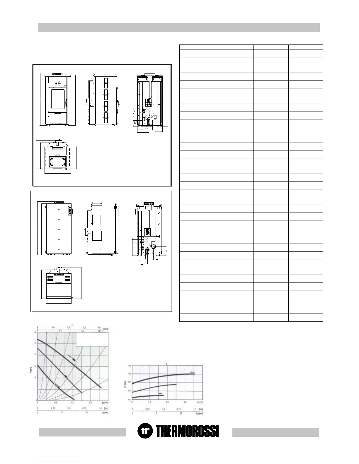
)mm(thgieH 2421
6621
)mm(htpeD 866
137
)mm(htgneL 765
065
)gK(thgieW 112
602
)wK(rewopdetarlatoT 6,21
6,01
)wK(rewopdetardecuderlatoT 7,4
5,4
)wK()retaw(rewopdetarlatoT 1,01
1,01
)wK()moor(rewopdetarlatoT 5,2
5,0
)retaw(rewopdetardecuderlatoT
)wK(
8,3
3,4
)wK()moor(rewopdetardecuderlatoT 9,0
2,0
ssalcrelioB 3
3
)h/gK(xam/nimnoitpmusnoC 8,2/9,0
5,2/9,0
)C°(erutarepmetgnitarepoxaM 37
37
)C°(erutarepmetnruter.niM 55
55
)mm(.DebutteltuoekomS 08
08
)aP(rewopdetartathguard.niM 01
01
)gK(yticapacreppoH 34
34
)l(tnetnocretaW 63
63
)rab(erusserpgnitarepO 1
1
)rab(erusserpgnitarepo.xaM 3
3
rewopdetarta.pmetekomsegarevA
)C°(
531
041
rewopdecuderta.pmetekomsegarevA
)C°(
18
68
detartaetarwolfekomS
)ces/gK(rewop
700,0
600,0
rewopdecudertaetarwolfekomS
)ces/gK(
8400,0
7400,0
)rabm(edisretaw-daolfossoL 3,0
3,0
yticirtcelE ZH05V022
ZH05V022
noitpmusnoclacirtcelexaM W253-A6,1
W253-A6,1
noitpmusnoclacirtceleegarevA W051-A7,0
W051-A7,0
nrutertnalpgnitaehA "4/3
"4/3
teltuo/telnireliobF "4/3
"4/3
evlavytefasE "2/1
"2/1
ebutyreviledtnalpgnitaehD "4/3
"4/3
)lanoitpo(telniretawdloccitsemodB "2/1
"2/1
)lanoitpo(teltuoretawtohcitsemodC "2/1
"2/1
emulovxamretawtohcitsemod
)lanoitpo(
*3.4.xorppa
nim/l
*3.4.xorppa
nim/l
CHARACTERISTIC
CURVES OF SINGLEPHASE PUMP
C
D
E
F
A- ritorno riscaldamento 3/4"
B- entrata acqua fredda sanitaria 1/2"
C- Uscita acqua calda sanitaria 1/2"
D- Mandata riscaldamento 3/4"
E- Valvola di sicurezza 1/2"
F - Carico -Scarico caldaia 3/4"
A
B
1214
1266
731
678
560
222
162
O 80
9460
142
259
148
65 116 65
A - Heating plant return 3/4''
B - Domestic cold water inlet 1/2''
C - Domestic hot water outlet 1/2''
D - Heating plant delivery tube 3/4''
E - Safety valve 1/2''
F - Boiler inlet/outlet 3/4''
F - Carico -Scarico caldaia 3/4"
E- Valvola di sicurezza 1/2"
D- Mandata riscaldamento 3/4"
C- Uscita acqua calda sanitaria 1/2"
B- entrata acqua fredda sanitaria 1/2"
A- ritorno riscaldamento 3/4"
1191
1242
567
521
616
668
148
249
142
42
162
222
F
H2O 14
65
11665
D
O
8
0
C
94
E
B
A
A - Heating plant return 3/4''
B - Domestic cold water inlet 1/2''
C - Domestic hot water outlet 1/2''
D - Heating plant delivery tube 3/4''
E - Safety valve 1/2''
F - Boiler inlet/outlet 3/4''
* The volume of domestic hot water refers to max
combustion power and temperature of water
flowing into the heat exchanger at 20 °C and water
flowing out of the heat exchanger at 60 °C.
* All the data are based on the appliance fuelled with Austrian standard ÖNORM M 7135 type-approved pellets.
Page 6
pg. VI
M
F
G
E
N
C
D
B
A
I
H
AD
O
Q
P
AD
33
33
3
GENERAL DESCRIPTIONGENERAL DESCRIPTION
GENERAL DESCRIPTIONGENERAL DESCRIPTION
GENERAL DESCRIPTION
3.13.1
3.13.1
3.1
OPERAOPERA
OPERAOPERA
OPERA
TING TING
TING TING
TING
TECHNOLTECHNOL
TECHNOLTECHNOL
TECHNOL
OGYOGY
OGYOGY
OGY
•Your heater / boiler has been constructed to satisfy in full all your heating and practical needs. Top-grade components and functions
managed with microprocessor technology guarantee high reliability and optimal performance.
3.23.2
3.23.2
3.2
PELLETSPELLETS
PELLETSPELLETS
PELLETS
•The appliance is fuelled by pellets, that is, cylinders of compressed sawdust; this will make it possible for you to enjoy to the full the flame without
having to manually stoke the combustion.
•The pellets are cylinders of compressed sawdust having a 6 mm diameter and a maximum length of 15 mm.
They have a maximum moisture content of 8%, a thermal value of 4000/4500 Kcal/Kg and a density of approx. 620-630 Kg/m³.
The use of fuel which does not comply with the description given above immediately voids the heater / boiler
warranty. Do not use the appliance as an incinerator, at the risk of voiding the warranty.
3.43.4
3.43.4
3.4
MAIN COMPONENTS OF HEAMAIN COMPONENTS OF HEA
MAIN COMPONENTS OF HEAMAIN COMPONENTS OF HEA
MAIN COMPONENTS OF HEA
TER MODTER MOD
TER MODTER MOD
TER MOD
..
..
.
H2O H2O
H2O H2O
H2O
AND BOILER MODAND BOILER MOD
AND BOILER MODAND BOILER MOD
AND BOILER MOD
..
..
.
COMP COMP
COMP COMP
COMP
AA
AA
A
CTCT
CTCT
CT
3.33.3
3.33.3
3.3
THE FEEDBOTHE FEEDBO
THE FEEDBOTHE FEEDBO
THE FEEDBO
XX
XX
X
The feedbox is situated in the top part of the heater / boiler.
The maximum load capacity of the tank is approximately 43 Kg, but varies
according to the specific weight of the pellets.
The manufacturer recommends emptying the hopper and vacuuming
the screw feeder zone once a month and during the summer period.
Take special care when loading the hopper as the screw feeder at its
base is in motion.
Page 7
pg. VII
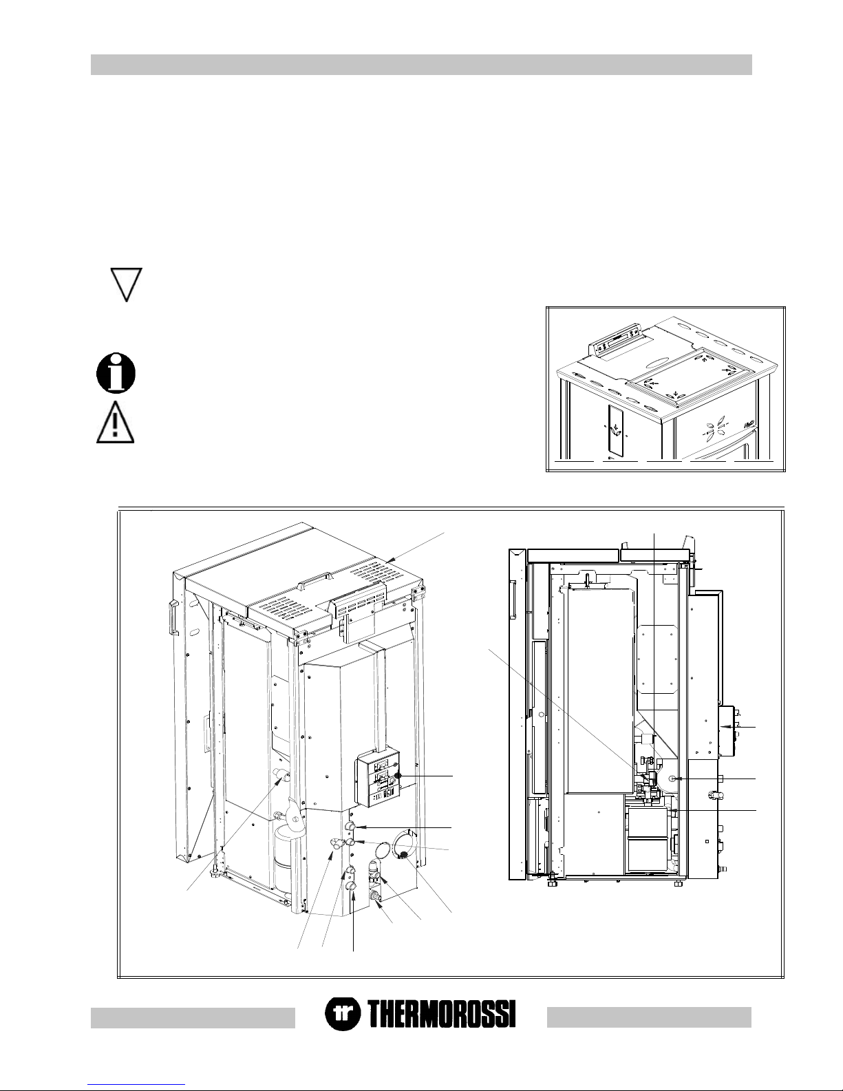
Z
U
AA
AC
R
V
T
S
X
Y
AF
W
AB
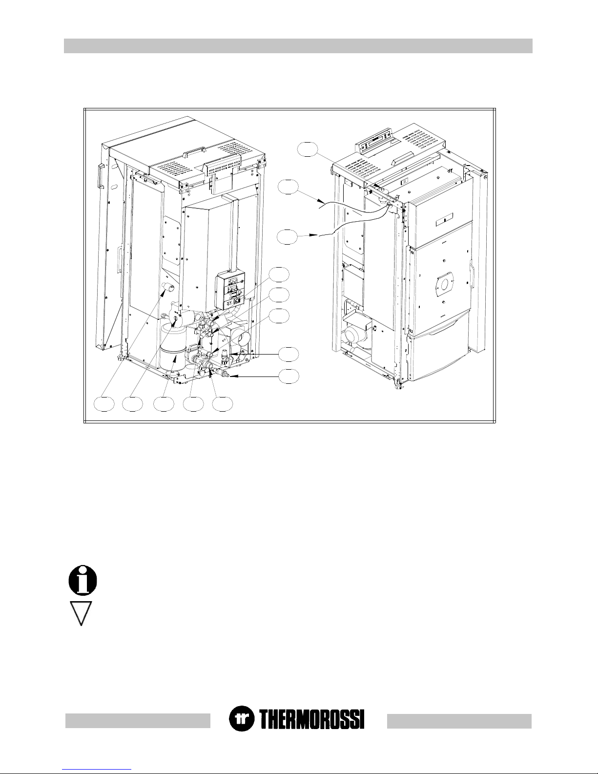
A : Heating plant return
B : Domestic cold water inlet 1/2''. (only with
Domestic Water Kit - optional -)
C : Domestic hot water outlet 1/2''. (only with
Domestic Water Kit - optional -)
D : Heating plant delivery tube 3/4".
E : Safety valve 3 bar 1/2".
F : Boiler Inlet - Outlet 3/4".
G : Smoke exhaust pipe
H : Safety thermostat 100° C.
I : Pellet hopper.
M : Pressure transducer.
N : System inlet (only with Domestic Water
Kit - optional - )
O : Expansion tank 2.5 l for protection of the
boiler only.
P : System circulating pump.
Q : Back panel of heater.
R : Thermostat 42°C.
S : Smoke suction unit
T : Electronic power board.
U : Cleaning brush
V : Pellet loading motor.
W : Tube bundle inspection cover.
X : Automatic relief valve.
Y : Pocket for heating system PTC sensor
and thermostat bulb 100°C reset.
Z : Burner.
AA: Ash pan.
AB: Control panel.
AC: Riddling tool.
AD: Spark plug.
AF: Smoke side pressure switch.
Page 8
pg. VIII
44
44
4
INSTINST
INSTINST
INST
ALLAALLA
ALLAALLA
ALLA
TIONTION
TIONTION
TION
4.14.1
4.14.1
4.1
HEAHEA
HEAHEA
HEA
TER / BOILER LTER / BOILER L
TER / BOILER LTER / BOILER L
TER / BOILER L
OCAOCA
OCAOCA
OCA
TIONTION
TIONTION
TION
CAUTION: Always use trolleys to move the appliance and the appliance
must always be in a vertical position. The casing for the H2O is packed
separately . On the contrary, to unpack the Compact, once the wood
crate has been removed, remove the casing (in reverse order as set
out in par.4.2.3). Remove the screw at the base of the heater / boiler
and remove the base from the bottom pallet.
Follow the general guidelines set out in paragraph 1.1 to the letter.
Above all ensure that the flooring of the room where the heater / boiler
will be installed is capable of bearing the weight of the appliance plus
the weight of the water contained in it and the weight of the pellets in
the hopper.
CAUTION: The room in which the appliance will operate must be
adequately ventilated (minimum air intake for an air flow of 1300 m3/h).
The heater / boiler must be positioned at a minimum safe distance
from walls and furnishings. This distance will have to be increased
considerably if the objects surrounding the appliance are
inflammable (matchboarding, furniture, curtains, picture frames,
sofas, etc...). The recommended minimum distances are illustrated
in the drawing below on the right. Installation in the vicinity of heatsensitive materials is only permitted if suitable insulating protection is
provided for ( ref. Uni 10683).
4.2.14.2.1
4.2.14.2.1
4.2.1
HOHO
HOHO
HO
W W
W W
W
TT
TT
T
O MOUNT H2O 14 HEAO MOUNT H2O 14 HEA
O MOUNT H2O 14 HEAO MOUNT H2O 14 HEA
O MOUNT H2O 14 HEA
TER CASINGTER CASING
TER CASINGTER CASING
TER CASING
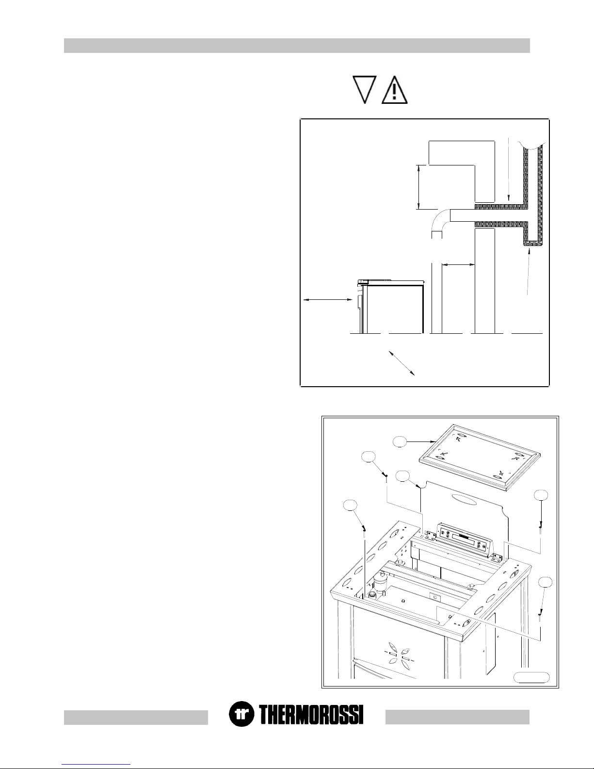
200 mm SE MATERIALE COMBUSTIBILE
200 mm SE MATERIALE
COMBUSTIBILE
450 mm SE MATERIALE COMBUSTIBILE
450 mm SE MATERIALE COMBUSTIBILE
Tee ispezionabile
ISOLANTE TERMICO
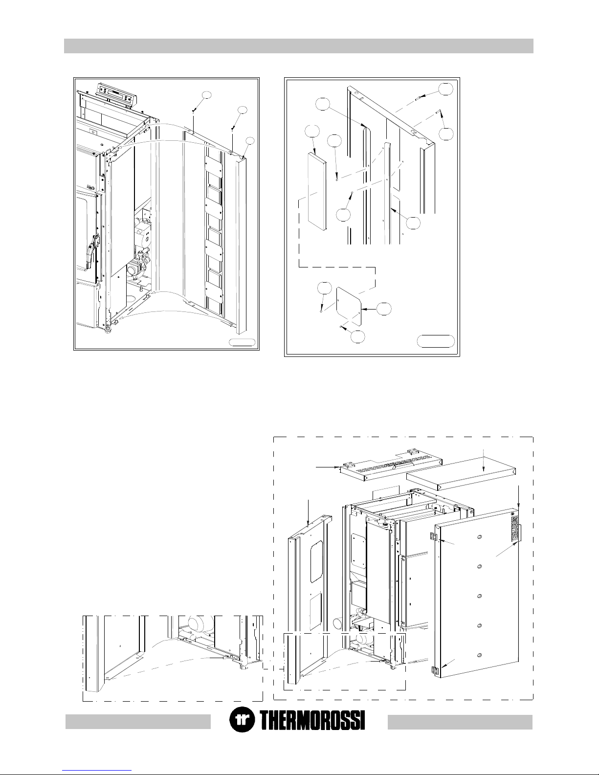
After positioning and levelling the heater by raising or lowering the mounting
feet, connecting it to the heating system and to the electrical system, the next
step is to mount the casing as shown in the image:
Carry out the steps described below as illustrated in figures 1,2,3:
- Open the pellets feed cover and remove the screws (C) (Figure 1).
- Remove the complete cover (B) (Figure 1).
- Next undo the first 2 screws (L) then remove the side panels (I) (Figure 2).
- Next fix the ceramic tiles on the side (G) as shown in Figure 3.
Take care not to over-tighten the nuts (F) as this could cause the tile to
break<>; this type of damage is not covered by warranty.
- After fixing the 4 ceramics proceed to mount the side panel (I) (Figure 2).
-Reassemble the complete cover (B) by fixing it with the screws (C) then
place the ceramics (A).
4.24.2
4.24.2
4.2
MOUNTING HEAMOUNTING HEA
MOUNTING HEAMOUNTING HEA
MOUNTING HEA
TERTER
TERTER
TER
/ BOILER/ BOILER
/ BOILER/ BOILER
/ BOILER
CASINGCASING
CASINGCASING
CASING
..
..
.
C
C
A
B
C
Figura 1
C
Key
200 / 450 mm if
combustible material
Heat insulating material
Inspectable Tee
element
Figure
LEGENDA
200 / 450 mm se materiale
combustibile
Isolante termico
Tee ispezionabile
Figura
Page 9
pg. IX
Figura 2
L
I
L
Figura 3
H
F
F
F
E
G
F
E
D
D
CP
F
T
P
M
C
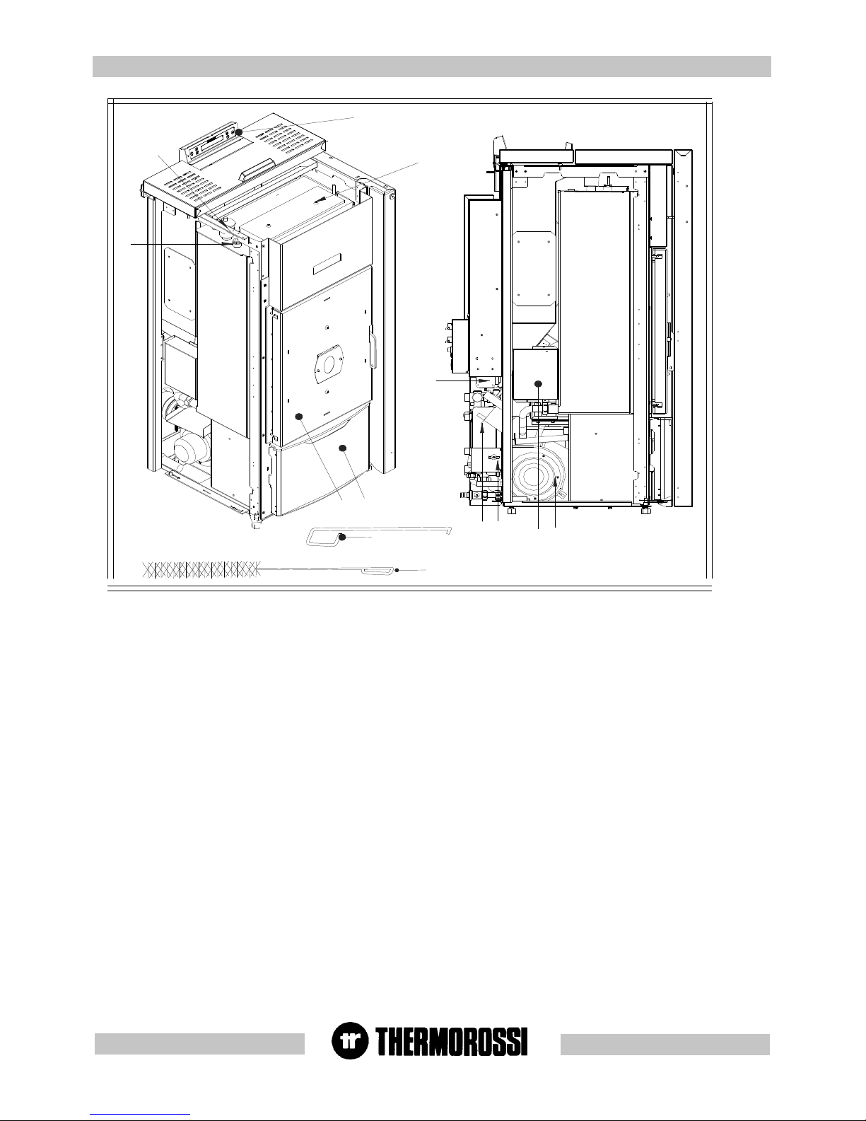
- Firstly remove the protective film from the casing.
- Next mount the 2 side panels (F) by inserting the 2 holes of the
bottom fold on the pins of the base and fastening the 2 top
screws with a screwdriver.
- Fasten the front cover (C) by fitting it onto the side panels.
- Fasten the door (P) to the left side with the special hinges and
screws provided.
- Lastly fit the back cover (CP) on the front cover (C) and
fasten the hinges with the screws provided.
If you prefer the door (P) can be mounted with the handle on the
left and the hinges on the right. Simply remove the handle (M)
from the door and fix it to the holes on the left side of the door,
remove the hinges (T) and fix them to the right side of the door.
Similarly, remove the magnet from the right side of the door and
mount it on the left side of the door.
After positioning and levelling the boiler by raising or lowering the mounting feet, connecting it to the heating system and to the electrical system
(see para. 4.4, 4.5, 4.6, 4.7, 4.8 and 4.9 ),proceed to mount the casing as illustrated:
4.2.34.2.3
4.2.34.2.3
4.2.3
HO HO
HO HO
HO
W W
W W
W
TT
TT
T
O MOUNT O MOUNT
O MOUNT O MOUNT
O MOUNT
THE COMPTHE COMP
THE COMPTHE COMP
THE COMP
AA
AA
A
CT BOILER CASINGCT BOILER CASING
CT BOILER CASINGCT BOILER CASING
CT BOILER CASING
Page 10
pg. X
VITE TC+ 4,8X13 (2 pz.)
G
VITE TC+ 4 ,8X 13 (2 pz.)
F
H
VITE TC+ 4,8X13
(2 pz.)
E
VITE TC+ 4,8X13 (2 pz.)
D
VITE TC+ 4,8X13 (4 pz.)
A
B
VITE TC+ 4,8X13 (4 pz.)
VITE TC+ 4,8X13 (2 pz.)
VITE TSP+ 8X50
+ DADO (4 pz.)
C
B1
H
F
I
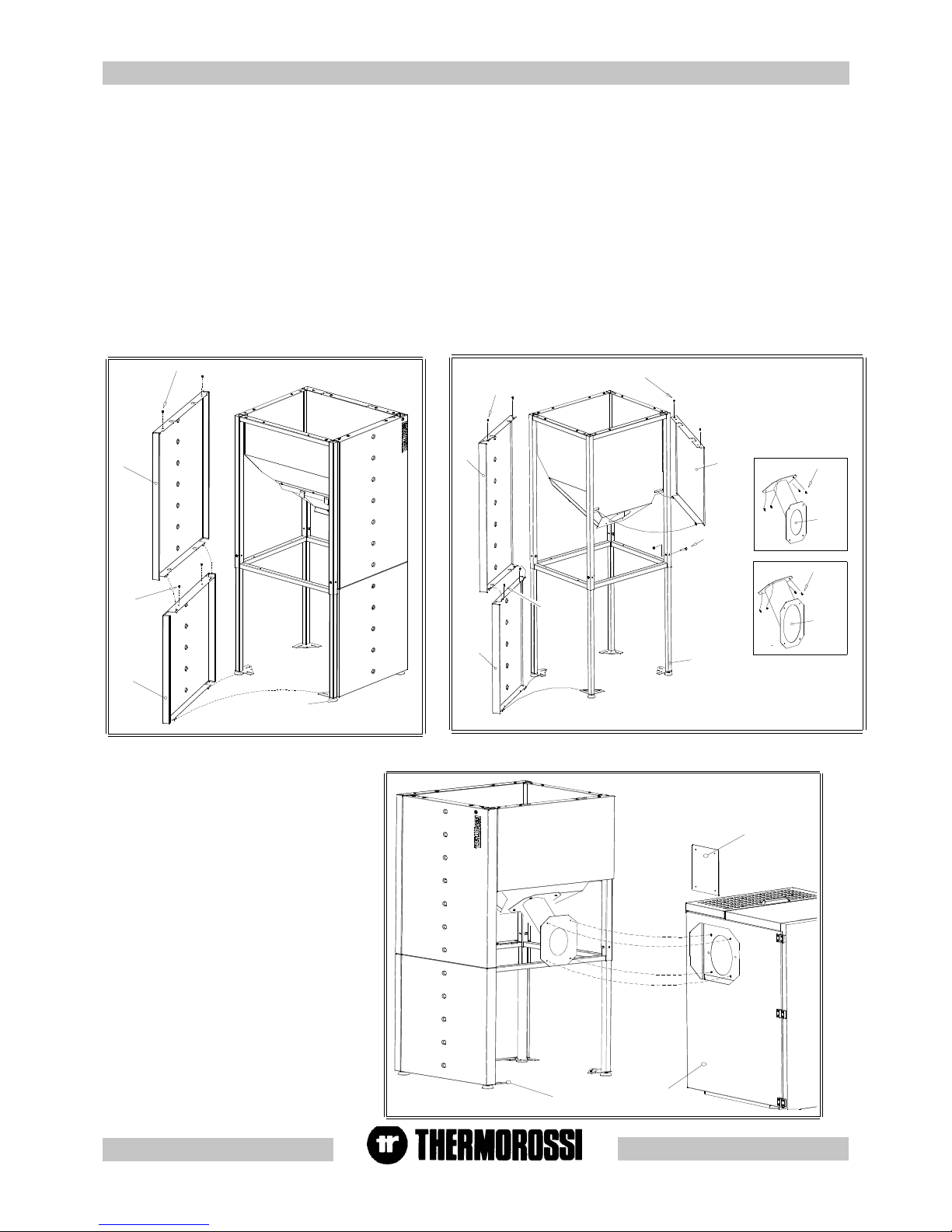
After having mounted the additional hopper
fasten the hopper to the boiler:
- Remove the octagonal portion of precut
sheet metal from the side (F) of the boiler
- Remove the cap (I) from the hopper by
undoing the screws fastened to it.
- Move the additional tank up against the
boiler by adjusting the mounting feet (H)
until the assembly is satisfactory.
- Fasten the assembly using the screws
previously removed from the cap (I).
4.2.54.2.5
4.2.54.2.5
4.2.5
HO HO
HO HO
HO
W W
W W
W
TT
TT
T
O FO F
O FO F
O F
ASTEN ASTEN
ASTEN ASTEN
ASTEN
THE THE
THE THE
THE
ADDITIONADDITION
ADDITIONADDITION
ADDITION
AL HOPPER (OPTIONAL HOPPER (OPTION
AL HOPPER (OPTIONAL HOPPER (OPTION
AL HOPPER (OPTION
AL) AL)
AL) AL)
AL)
TT
TT
T
O COMPO COMP
O COMPO COMP
O COMP
AA
AA
A
CT BOILER.CT BOILER.
CT BOILER.CT BOILER.
CT BOILER.
To increase the boiler's autonomy of operation it is possible to install one or two additional hoppers at the sides of the boiler. Each additional hopper
can hold up to 100 Kg of pellets.
Firstly unpack the hopper then assemble it as follows:
- Fasten the 4 telescopic legs (A) using the screws provided (screws TSP+ 8x50).
- Fasten the pellet chute (attention: use chute B1) to the hopper using the screws provided (screws TC+4.8x13).
- Mount the panel (C) by inserting the bottom folds on the holes of the hopper, and then securing it using the screws provided (screws
TC+4.8x13).
- Similarly fasten the panel (E) using the screws provided (screws TC+4.8x13).
- Then mount the panel (D) by lining up the lower rectangular holes on the panel folds (E) and fastening them using the screws provided (screws
TC+4.8x13).
- The panels (D) and (E) can be mounted either to the right or to the left of the pellet chute (B1); if mounted on the right the additional hopper will
have to be mounted to the right of the boiler. .
- Fix the panel (G) by firstly inserting the holes on the bottom on the mounting feet then securing them with the screws provided (screws
TC+4.8x13).
- Next mount the panel (F) by inserting the bottom folds on the holes in the panel (G).
4.2.44.2.4
4.2.44.2.4
4.2.4
HO HO
HO HO
HO
W W
W W
W
TT
TT
T
O INSTO INST
O INSTO INST
O INST
ALL ALL
ALL ALL
ALL
ADDITIONADDITION
ADDITIONADDITION
ADDITION
AL HOPPER (OPTIONAL HOPPER (OPTION
AL HOPPER (OPTIONAL HOPPER (OPTION
AL HOPPER (OPTION
AL) AL)
AL) AL)
AL)
WITH COMPWITH COMP
WITH COMPWITH COMP
WITH COMP
AA
AA
A
CT BOILER.CT BOILER.
CT BOILER.CT BOILER.
CT BOILER.
Key
SCREW
NUT
LEGENDA
Vite
Dado
Page 11
pg. XI
A : Heating plant return
C : Domestic hot water outlet 1/2''. (only
with Domestic Water Kit - optional -)
E : Safety valve 3 bar 1/2".
H : Safety thermostat 100° C.
M : Pressure transducer.
O : Expansion tank 2.5 l for protection of
the boiler only.
X : Automatic relief valve.
4.34.3
4.34.3
4.3
HYDRA HYDRA
HYDRA HYDRA
HYDRA
ULIC DRAULIC DRA
ULIC DRAULIC DRA
ULIC DRA
WING FOR HEAWING FOR HEA
WING FOR HEAWING FOR HEA
WING FOR HEA
TER HTER H
TER HTER H
TER H
22
22
2
O / COMPO / COMP
O / COMPO / COMP
O / COMP
AA
AA
A
CTCT
CTCT
CT
CAUTION: FOR THE DELIVERY , RETURN, MAKE-UP AND DISCHARGE CONNECTIONS USE FLEXIBLE TUBES HA VING A LENGTH
OF AT LEAST 70 CM TO FACILITATE MOVING THE APPLIANCE FOR MAINTENANCE.
CAUTION: A CONNECTION MUST BE MADE BETWEEN THE SAFETY V AL VE AND THE OUTLET TO PREVENT DAMAGING
MATERIALS SURROUNDING THE BOILER/HEA TER WHEN THE V AL VE IS ACTIVA TED.
(SEE PAR. 4.4 - 4.5 - 4.6 - 4.7 - 4.8 - 4.9).
F
PM O N D
B
E
C
1
A
X
H
B : Domestic cold water inlet 1/2''. (only with
Domestic Water Kit - optional -)
D : Heating plant delivery tube 3/4".
F : Boiler Inlet - Outlet 3/4". (only with
Domestic Water Kit - optional -)
N : System Inlet
P : System circulating pump.
1 : Boiler sensor
Page 12
pg. XII
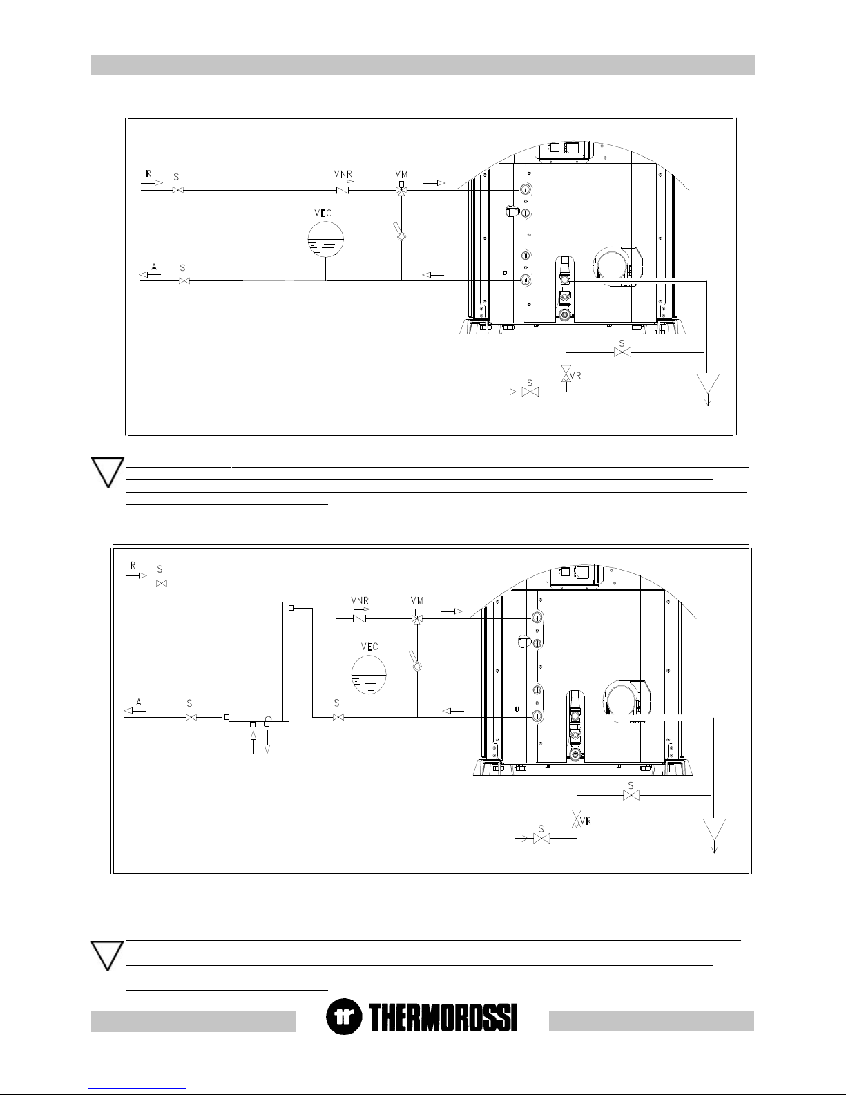
4.4 EXAMPLE OF HYDRA4.4 EXAMPLE OF HYDRA
4.4 EXAMPLE OF HYDRA4.4 EXAMPLE OF HYDRA
4.4 EXAMPLE OF HYDRA
ULIC DRAULIC DRA
ULIC DRAULIC DRA
ULIC DRA
WING FOR HWING FOR H
WING FOR HWING FOR H
WING FOR H
22
22
2
O / COMPO / COMP
O / COMPO / COMP
O / COMP
AA
AA
A
CT ONLCT ONL
CT ONLCT ONL
CT ONL
Y HEAY HEA
Y HEAY HEA
Y HEA
TINGTING
TINGTING
TING
4.5 EXAMPLE OF HYDRA4.5 EXAMPLE OF HYDRA
4.5 EXAMPLE OF HYDRA4.5 EXAMPLE OF HYDRA
4.5 EXAMPLE OF HYDRA
ULIC DRAULIC DRA
ULIC DRAULIC DRA
ULIC DRA
WING HWING H
WING HWING H
WING H
22
22
2
0 / COMPACT WITH INTERSPACED BOILER COILS OR BOILER COILS
Caution: it is mandatory to earth the heater / boiler. If this instruction is not observed serious damage, which is not
covered by warranty, will result to the body of the heater / boiler.Have an electrician check the earthing. There must
be no electric potential (volts) between the earth of the generator and the actual earth of the plant. To prevent
electrochemical corrosion of the boiler body do not use galvanised pipes and fittings. Dedicated ground wires must
be used to ground all other materials.
Caution: it is mandatory to earth the heater / boiler. If this instruction is not observed serious damage, which is not
covered by warranty, will result to the body of the heater / boiler. Have an electrician check the earthing. There must
be no electric potential (volts) between the earth of the generator and the actual earth of the plant. To prevent
electrochemical corrosion of the boiler body do not use galvanised pipes and fittings. Dedicated ground wires must
be used to ground all other materials.
A : andata impianto riscaldamento
R : ritorno impianto riscaldamento
S : saracinesca
VNR : valvola di non ritorno
VEC : vaso di espansione chiuso per protezione impianto
VR : valvola riduttrice di pressione
VM : valvola miscelatrice termostatica punto fisso 55°c
VSP: valvola saracinesca (da parzializzare in funzione
delle perdite di carico dell'impianto).
CAUTION : The water temperature in the boiler tubes in this case is not adjustable and depends on the systems's delivery temperature, that
is the boiler temperature setting. The boiler tubes can be installed on the water return circuit. Moreover, the Manufacturer recommends
installing a water softener in the domestic hot water system in order to prevent the formation of limescale deposits in the boiler tubes which
could compromise their functionality.
A : andata impianto riscaldamento
R : ritorno impianto riscaldamento
S : saracinesca
VNR : valvola di non ritorno
VEC : vaso di espansione chiuso per protezione impianto
VR : valvola riduttrice di pressione
VM : valvola miscelatrice termostatica punto fisso 55°c.
VSP: valvola saracinesca (da parzializzare in funzione
delle perdite di carico dell'impianto)
A: heating plant delivery
R: heating plant return
S: gate valve
VNR: nonreturn valve
VEC: closed expansion tank for plant protection
VR: reducing valve
VM: thermostatic mixing valve, fixed point 55°C
VSP: gate valve (throttle according to pressure drop in the system)
DAR: From water mains for make-up
SC: discharge
DAR
SC
A: heating plant delivery
R: heating plant return
S: gate valve
VNR: nonreturn valve
VEC: closed expansion tank for plant protection
VR: reducing valve
VM: thermostatic mixing valve, fixed point 55°C
VSP: gate valve (throttle according to pressure drop in the system)
DAR: From water mains for make-up
SC: discharge
BAI: Interspaced boiler coils or boiler coils
DAR
SC
BAI
Page 13

pg. XIII
4.6.14.6.1
4.6.14.6.1
4.6.1
TT
TT
T
herher
herher
her
mocontrmocontr
mocontrmocontr
mocontr
ol electrical connection wol electrical connection w
ol electrical connection wol electrical connection w
ol electrical connection w
herher
herher
her
e the H2O 14 / COMPe the H2O 14 / COMP
e the H2O 14 / COMPe the H2O 14 / COMP
e the H2O 14 / COMP
AA
AA
A
CT 14 boiler is inteCT 14 boiler is inte
CT 14 boiler is inteCT 14 boiler is inte
CT 14 boiler is inte
gg
gg
g
rr
rr
r
aa
aa
a
tedted
tedted
ted
in a plumbing system with boiler coils.in a plumbing system with boiler coils.
in a plumbing system with boiler coils.in a plumbing system with boiler coils.
in a plumbing system with boiler coils.
The following is a description of the electric wiring for Thermocontrol and H2O 14 / Compact 14: through this electrical
connection, the shut off action by Thermocontrol automatically switches the diverter valve and also switches off the boiler: if the
system Chronothermostat requires more heat the boiler does not switch off until it has satisfied the heating requirements of the
room. The connections to the diverter valve and system chronothermostat are shown in the diagram and in the following photos.
CAUTION: in order to prevent too many boiler start ups, with consequent reduction in the electrical heater lifetime, the
manufacturer highly recommends using a chronothermostat with a thermal hysteresis of at least 2°C.
" CRONOTERMOSTATO - MODEM " sul pannello posteriore
ON / OFF ECOTHERM (da collegare al connettore
termica minima di 2°C).
Cronotermostato (con isteresi
posteriore
Pannello
Valvola deviatrice
220 V 50 Hz
N F
220 V 50 Hz
Alimentazione
N F
Thermocontrol
Caution: it is mandatory to earth the heater / boiler. If this instruction is not observed serious damage, which is not
covered by warranty, will result to the body of the heater / boiler. Have an electrician check the earthing. There
must be no electric potential (volts) between the earth of the generator and the actual earth of the plant. To prevent
electrochemical corrosion of the boiler body do not use galvanised pipes and fittings. Dedicated ground wires
must be used to ground all other materials.
In order to guarantee correct absorption of the heat produced by the generator is it is advisable to use a boiler tube with volume and heat
exchange capacity suitable for the power of the generator.
See key page XLIV
TB : termostato bollitore
VR : valvola riduttrice di pressione
VM : valvola miscelatrice termostatica punto fisso 55°c.
VDEV3V : valvola deviatrice 3 vie
THER : thermocontrol
A : andata impianto riscaldamento
R : ritorno impianto riscaldamento
S : saracinesca
VNR : valvola di non ritorno
VEC : vaso di espansione chiuso per protezione impianto
VSP : valvola saracinesca ( da parzializzare in funzione
delle perdite di carico dell'impianto).
DAR
SC
CCI
CCT
A: heating plant delivery
R: heating plant return
S: gate valve
VNR: nonreturn valve
VEC: closed expansion tank for plant protection
VSP: gate valve (throttle according to pressure drop in
the system)
VR: reducing valve
TB: reducing valve
VM: thermostatic mixing valve, fixed point
55°C
VDEV3V: Three-way diverting valve
THER: Thermocontrol
CCI: system chronothermostat contact
CCT: Chronothermostat modem contact
DAR: From water mains for make-up
SC: discharge
4.64.6
4.64.6
4.6
EXAMPLE OF HYDRAEXAMPLE OF HYDRA
EXAMPLE OF HYDRAEXAMPLE OF HYDRA
EXAMPLE OF HYDRA
ULIC DRAULIC DRA
ULIC DRAULIC DRA
ULIC DRA
WING HWING H
WING HWING H
WING H
22
22
2
0/COMP0/COMP
0/COMP0/COMP
0/COMP
AA
AA
A
CT CT
CT CT
CT
WITH BOILER COILS WITH BOILER COILS
WITH BOILER COILS WITH BOILER COILS
WITH BOILER COILS
AND USE OF AND USE OF
AND USE OF AND USE OF
AND USE OF
THERMOCONTRTHERMOCONTR
THERMOCONTRTHERMOCONTR
THERMOCONTR
OLOL
OLOL
OL
(OPTIONAL)(OPTIONAL)
(OPTIONAL)(OPTIONAL)
(OPTIONAL)
Page 14

pg. XIV
4.74.7
4.74.7
4.7
EXAMPLE OF HYDRAEXAMPLE OF HYDRA
EXAMPLE OF HYDRAEXAMPLE OF HYDRA
EXAMPLE OF HYDRA
ULIC DRAULIC DRA
ULIC DRAULIC DRA
ULIC DRA
WING FOR H20 /COMPWING FOR H20 /COMP
WING FOR H20 /COMPWING FOR H20 /COMP
WING FOR H20 /COMP
AA
AA
A
CT CT
CT CT
CT
WITH "KIT FOR WITH "KIT FOR
WITH "KIT FOR WITH "KIT FOR
WITH "KIT FOR
THE PRTHE PR
THE PRTHE PR
THE PR
ODUCTIONODUCTION
ODUCTIONODUCTION
ODUCTION
OF INSTOF INST
OF INSTOF INST
OF INST
ANT DOMESTIC HOANT DOMESTIC HO
ANT DOMESTIC HOANT DOMESTIC HO
ANT DOMESTIC HO
T T
T T
T
WW
WW
W
AA
AA
A
TER TER
TER TER
TER
" (OPTIONAL).
The diverting valve switches the water to the plate heat exchanger of the "Domestic hot water production kit " when the flow switch detects
the passage of water towards the usage point and when the boiler temperature exceeds 61° C. When there is a request for hot water the
boiler operates at maximum steady state power level. See also paragraph 5.9.
Ecotherm
ON - OFF
CAUTION: it is mandatory to earth the heater / boiler. If this instruction is not observed serious damage, which is not
covered by warranty, will result to the body of the heater / boiler. Have an electrician check the earthing. There must
be no electric potential (volts) between the earth of the generator and the actual earth of the plant. To prevent
electrochemical corrosion of the boiler body do not use galvanised pipes and fittings. Dedicated ground wires must
be used to ground all other materials.
Rubinetto di carico impianto riscaldamento
A : andata impianto riscaldamento VNR : valvola di non ritorno
R : ritorno impianto riscaldamento VEC : vaso di espansione
S : saracinesca chiuso per protezione impianto
VR : valvola riduttrice di pressione VM : valvola miscelatrice termostatica punto fisso 55°c.
VSP : valvola saracinesca (da parzializzare in funzione delle perdite di carico dell'impianto).
A: heating plant delivery
R: heating plant return
S: gate valve
VR: reducing valve
VSP: gate valve (throttle according to pressure drop in
the system)
VNR: nonreturn valve
VEC: closed expansion tank for plant
protection
VM: thermostatic mixing valve, fixed point
55°C
See key page XLIV
Page 15

pg. XV
CAUTION: CONNECT , AS INDICATED, THE CONNECT ORS SUPPLIED WITH THE KIT FOR THE PRODUCTION OF
INSTANT DOMESTIC HOT WATER . THIS OPERATION MUST BE CARRIED OUT WITH THE ' " MAIN SWITCH 0-1
" INSTALLED AT THE BACK IN POSITION " 0 ".
FLUSSOSTATO
TUBO MANDATA
RISCALDAMENTO
COLLARE FERMATUBO
COMPLETO DI VITE
VALVOLA DEVIATRICE
GUARNIZIONE
CAVO VALVOLA
DEVIATRICE
CORPO RITORNO
I
M
P
I
A
N
T
O
R
I
S
C
A
L
D
A
M
E
N
T
O
SCAMBIATORE
A PIASTRE
GUARNIZIONE
CORPO MANDATA
R
U
B
I
N
E
T
T
O
C
A
R
I
C
O
VITE
VITE
CAVO FLUSSOSTATO
The heater H2O / boiler Compact can be supplied with a
" Kit for the production of instant domestic hot water" (see par. 4.7) . When
a tap is turned on, the " flow switch" commands the " diverting valve" to
convey the hot water from the boiler to the plate heat exchanger . The
temperature of the domestic hot water obtained in this way is roughly 10° 15° lower than the temperature in the boiler as indicated on the handheld
radio control and in any case within the limits indicated in par. 2.
Hot water is not available when the boiler is switched off. When
the boiler switched on, upon a request for hot water, it operates at
the maximum steady state level of combustion: the diverting valve
only conveys the water to the plate heat exchanger if the temperature in the boiler is above 61°.
The manufacturer recommends installing a water softener to ensure an
optimal life of the plate heat exchanger (see par. 4.7). It is also advisable to
regularly clean and check the plate heat exchanger.
The Kit for the production of instant domestic hot water comprises:
4.7.1 MOUNTING 4.7.1 MOUNTING
4.7.1 MOUNTING 4.7.1 MOUNTING
4.7.1 MOUNTING
THE KIT FOR THE KIT FOR
THE KIT FOR THE KIT FOR
THE KIT FOR
THE PRTHE PR
THE PRTHE PR
THE PR
ODUCTION OF INSTODUCTION OF INST
ODUCTION OF INSTODUCTION OF INST
ODUCTION OF INST
ANT DOMESTIC HOANT DOMESTIC HO
ANT DOMESTIC HOANT DOMESTIC HO
ANT DOMESTIC HO
T T
T T
T
WW
WW
W
AA
AA
A
TER (OPTIONTER (OPTION
TER (OPTIONTER (OPTION
TER (OPTION
AL)AL)
AL)AL)
AL)
RETRO INFERIORE
RISCALDAMENTO ( TIPO 1 )
FERMATUBO
VITI DI MONTAGGIO
GRUPPO COMPLETO
GUARNIZIONE
PREMONTATO.
VITE
VITE
VITE
COLLARE
DI SCARICO
RUBINETTO
RISCALDAMENTO ( TIPO 2 )
GRUPPO COMPLETO
PREMONTATO
TUBO MANDATA
COMPLETO PREMONTATO
SUPPORTO GRUPPO
GHIERA
TUBO MANDATA
GUARNIZIONE
VITE
VITE
VITE
VITE
VITE
VITE
Installation of the " Kit for the production of instant domestic hot water"
must be made as indicated below:
- Empty the boiler completely by acting on the "drain tap" and empty or shut
off the system.
-Remove the ring nut from the "delivery tube to heating system (type 1)".
-Remove, by acting on the indicated screws, the "bottom back plate" and
the "complete preassembled unit support".
-Next remove the "delivery tube to heating system (type 1) " fastened to the
boiler.
-Fasten the " locking band " as indicated.
-Fasten the " delivery tube to heating system (type 2) " with the
corresponding gasket.
-Connect the " complete preassembled unit" to the " delivery tube to heating
system and to the circulating pump of the boiler with the corresponding
gaskets.
-Next fasten the "preassembled unit support" with the corresponding
screws.
-Firmly fasten the "complete preassembled unit" with the "screws for
mounting the complete preassembled unit " to the "complete preassembled
unit support".
-Lastly fasten the "bottom back plate".
-Then make the hydraulic connections between the heater / boiler and the
system and fill up with water.
4.7.24.7.2
4.7.24.7.2
4.7.2
HYDRAHYDRA
HYDRAHYDRA
HYDRA
ULIC INSTULIC INST
ULIC INSTULIC INST
ULIC INST
ALLAALLA
ALLAALLA
ALLA
TION FOR " KIT FOR TION FOR " KIT FOR
TION FOR " KIT FOR TION FOR " KIT FOR
TION FOR " KIT FOR
THETHE
THETHE
THE
PRPR
PRPR
PR
ODUCTION OF INSTODUCTION OF INST
ODUCTION OF INSTODUCTION OF INST
ODUCTION OF INST
ANT DOMESTIC HOANT DOMESTIC HO
ANT DOMESTIC HOANT DOMESTIC HO
ANT DOMESTIC HO
T T
T T
T
WW
WW
W
AA
AA
A
TER TER
TER TER
TER
"
CAUTION: CHECK CAREFULL Y THA T THE "HEA TING SYSTEM WA TER INLET TAP" IS CLOSED BEFORE MAKING THE
HYDRAULIC CONNECTIONS BETWEEN THE BOILER AND SYSTEM.
- 1 Complete Unit, preassembled,
consisting of a plate heat
exchanger, heating system inlet
tap, diverting valve, flow switch,
brass delivery body, brass return
body.
-1 complete locking band .
4.7.3 ELECTRICAL INST4.7.3 ELECTRICAL INST
4.7.3 ELECTRICAL INST4.7.3 ELECTRICAL INST
4.7.3 ELECTRICAL INST
ALLAALLA
ALLAALLA
ALLA
TION FOR " KIT FOR TION FOR " KIT FOR
TION FOR " KIT FOR TION FOR " KIT FOR
TION FOR " KIT FOR
THE PRTHE PR
THE PRTHE PR
THE PR
ODUCTION OF INSTODUCTION OF INST
ODUCTION OF INSTODUCTION OF INST
ODUCTION OF INST
ANT DOMESTIC HOANT DOMESTIC HO
ANT DOMESTIC HOANT DOMESTIC HO
ANT DOMESTIC HO
TT
TT
T
WW
WW
W
AA
AA
A
TER TER
TER TER
TER
"
- 2 Gaskets.
- 1 Hot water delivery tube to the
heating system.
- 1 Flow switch cable.
- 1 Diverting valve cable.
-2 screws for fastening the unit.
See key page XLIV
Page 16

pg. XVI
FLUSSOSTATO
CONNESSIONE
VALVOLA DEVIATRICE
CONNESSIONE
CAUTION: CONNECT THE FLOW SWITCH CABLE TAKING CARE TO ASSEMBLE IT AS ILLUSTRATED IN THE IMAGE:
CONNECTIONS THAT ARE DIFFERENT TO THOSE INDICATED WILL LEAD TO BREAKAGE OF THE FLOW SWITCH
BOARD (DAMAGE NOT COVERED BY THE WARRANTY).
See key page XLIV
See key page XLIV
Page 17

pg. XVII
Valvola miscelatrice 3 vie termostatica 55°c
Valvola saracinesca (da parzializzare in
funzione delle perdite di carico dell'impianto
Tubi di collegamento accumuli
Vaso di espansione chiuso
Attenzione : chiudere tutti i fori
non usati del puffer
Sonda 2
Sonda 1
Thermopuffer aggiuntivo
punto fisso.
Mandata caldaia
non usati del puffer
Attenzione : chiudere tutti i fori
Riscaldamento pavimento
Radiatori
Ritorno caldaia
Valvola a 3 vie
Thermocell o Thermopuffer
Circolatore
Valvola di non ritorno
Valvola 3 vie manuale
Saracinesca
4.84.8
4.84.8
4.8
SCHEMASCHEMA
SCHEMASCHEMA
SCHEMA
TIC DRATIC DRA
TIC DRATIC DRA
TIC DRA
WING OF WING OF
WING OF WING OF
WING OF
TYPICAL HYDRATYPICAL HYDRA
TYPICAL HYDRATYPICAL HYDRA
TYPICAL HYDRA
ULIC CIRULIC CIR
ULIC CIRULIC CIR
ULIC CIR
CUIT FOR H20 / COMPCUIT FOR H20 / COMP
CUIT FOR H20 / COMPCUIT FOR H20 / COMP
CUIT FOR H20 / COMP
AA
AA
A
CT +CT +
CT +CT +
CT +
THERMOCELL (OR THERMOCELL (OR
THERMOCELL (OR THERMOCELL (OR
THERMOCELL (OR
THERMOPUFFER) + THERMOPUFFER) +
THERMOPUFFER) + THERMOPUFFER) +
THERMOPUFFER) +
ADDITIONADDITION
ADDITIONADDITION
ADDITION
AL AL
AL AL
AL
THERMOPUFFER + HIGH THERMOPUFFER + HIGH
THERMOPUFFER + HIGH THERMOPUFFER + HIGH
THERMOPUFFER + HIGH
TEMPERATEMPERA
TEMPERATEMPERA
TEMPERA
TU-TU-
TU-TU-
TU-
RE HEARE HEA
RE HEARE HEA
RE HEA
TING TING
TING TING
TING
AND LAND L
AND LAND L
AND L
OO
OO
O
W W
W W
W
TEMPERATEMPERA
TEMPERATEMPERA
TEMPERA
TURE HEATURE HEA
TURE HEATURE HEA
TURE HEA
TINGTING
TINGTING
TING
CAUTION: The system operating pressure must always be above the expansion tank preload: If the operating pressure of the system is
2 bar, the expansion tank must be preloaded to 1.5 bar.
CAUTION: The Thermocell must also be connected only to 220V - 50Hz power supply"; the adjustments of Sensor 1 and Sensor 2 must
be controlled by the heater / boiler and not by the Thermocell electric panel.
For this purpose connect 2 thermocouples (optional code no. 60010695) to the cable clamps of Sensor 1 and Sensor 2" of
the heater / boiler.
CAUTION: Sensor S1 must be set at 65°C (over 65°C it switches off the boiler ). Sensor S2 must be set at 4045°C (under 40 - 45°C it
switches on the boiler).
CAUTION: it is mandatory to earth the heater / boiler. If this instruction is not observed serious damage, which is
not covered by warranty, will result to the body of the heater / boiler. Have an electrician check the earthing.
There must be no electric potential (volts) between the earth of the generator and the actual earth of the plant. To
prevent electrochemical corrosion of the boiler body do not use galvanised pipes and fittings. Dedicated ground
wires must be used to ground all other materials.
See key page
XLIV
Page 18

pg. XVIII
The safety valve must be connected to the highest part of the heat generator or the outlet tube, next to the generator. The length of the section
of tube between the generator fitting and the safety valve must not be more than one metre. There must be no cocks that can cut off the tube
connecting the safety valve to the heat generator and the section must not be less than the inlet section of the safety valve or the sum of the inlet
sections if there are several valves that head a single tube, at any point whatsoever along its length. The outlet tube of the safety valve must be
installed in such a way that it does not prevent the normal functioning of the valves and will not cause injury to persons ; the outlet must be located
as close as possible to the safety valve and be accessible and visible. The diameter of the outlet tube must not in any case be less than the
diameter of the safety valve outlet fitting. The outlet fitting diameter is the minimum internal diameter of the valve outlet upstream from any existing
internal threading. The valve discharge pressure, equal to the calibration pressure and increased by the overpressure, must not exceed the
maximum working pressure of the heat generator. The designer must ensure that the maximum pressure existing at every point of the system
does not exceed the maximum working pressure of each of its components. The discharge capacity of the safety valve must be calculated
according to the prescriptions set out in UNI 10412/2. The diameter of the minimum net cross section of the valve inlet must in any case be not
less than 15 mm. The maximum working pressure of the closed expansion tank must not be less than the calibration pressure of the
safety valve, plus the specific overpressure of the valve itself, with any difference in height between the tank and the valve taken into
account,and the pressure generated by the functioning of the pump. The capacity of the expansion tank or tanks is evaluated according to the
overall capacity of the plant as per the design. The closed expansion tanks must comply with current regulations governing pressure appliances
in terms of design, construction, conformity assessment and utilization.
The rated volume of the closed expansion tank must be sized in relation to the expansion volume of the water in the
system.
The heat generator must be connected directly to the plant's expansion tank or group of expansion tanks with a tube having an internal
diameter no less than 18 mm. The connecting tube, which may consist of plant parts, must not be fitted with any shutoff cocks or have reduced
sections. One three-way on-off valve may be installed for connecting the tank to the atmosphere for maintenance operations. This device must
be protected against accidental manoeuvres. The connecting tube must be fitted in such a way that no scaling or deposit points are created. If
several heat generators power a single system or secondary circuit, each heat generator must be connected directly to the system's expansion
tank or group of expansion tanks sized overall for the total volume of water contained in the same plant or independent circuit. When it is
necessary to separate the single heat generator from the expansion tank or group of expansion tanks, then a three-way tap having the same
characteristics as those listed above must be installed on the tube that connects the generator to the expansion tank, in order to ensure that the
generator is in any case connected either with the expansion tank or with the atmosphere in every position. The expansion tanks, connecting
tubes, the vent and smoke exhaust pipes must be protected against freezing in areas where this could occur. The solution adopted for this
purpose must be described in the project. Given that the circulation of the water in the heat generator must be maintained in any system and in
all operating conditions within the limits prescribed by the supplier of the generator, in closed expansion tank heating systems, in which the
circulation of the water is assured by means of an electric pump, the pump stopping must not cause, in any operating condition, the temperature
to rise above the limit prescribed in these instructions.
The previous chapter does not replace UNI 10412/2 to which it makes reference . The qualified installer must in any case be
fully aware of this standard and its amending versions.
4.9 INSTR4.9 INSTR
4.9 INSTR4.9 INSTR
4.9 INSTR
UCTIONS FOR EXECUTING UCTIONS FOR EXECUTING
UCTIONS FOR EXECUTING UCTIONS FOR EXECUTING
UCTIONS FOR EXECUTING
THE HYDRATHE HYDRA
THE HYDRATHE HYDRA
THE HYDRA
ULIC SYULIC SY
ULIC SYULIC SY
ULIC SY
STEM CLSTEM CL
STEM CLSTEM CL
STEM CL
OSED EXPOSED EXP
OSED EXPOSED EXP
OSED EXP
ANSION ANSION
ANSION ANSION
ANSION
TT
TT
T
ANK.ANK.
ANK.ANK.
ANK.
Systems with closed expansion tank, must be provided with :
a) safety valve b) thermal relief valve or thermal safety outlet (positive safety )
c) closed expansion tank d) circulating pump activation thermostat (included in the panel of the central heating cooker).
e) acoustic alarm activation thermostat f) acoustic alarm
g) pressure gauge thermometer h) circulation system
These devices must be installed on the generator's delivery tube, within not more than 1 metre from the machine.
4.8.1 CONNECTION OF SENSORS S1 4.8.1 CONNECTION OF SENSORS S1
4.8.1 CONNECTION OF SENSORS S1 4.8.1 CONNECTION OF SENSORS S1
4.8.1 CONNECTION OF SENSORS S1
AND S2 AND S2
AND S2 AND S2
AND S2
TT
TT
T
O O
O O
O
THE REAR PTHE REAR P
THE REAR PTHE REAR P
THE REAR P
ANEL OF ANEL OF
ANEL OF ANEL OF
ANEL OF
THE HEATHE HEA
THE HEATHE HEA
THE HEA
TER / BOILER.TER / BOILER.
TER / BOILER.TER / BOILER.
TER / BOILER.
Sensor S2 and sensor S1 must be connected to the dedicated clamps on the rear panel (see para. 5.2). To activate the detections of
Sensors S1 and S2 set THERMOCONTROL ON (see para. 5.8).
Page 19

pg. XIX
(1) Insert on/off and flame adjustment button . When you press this button the appliance (7) switches to START / OFF. Press
repeatedly to activate up to 5 bars and the AUTO indicator is activated (automatic).
START - start up phase: during this phase (lasts approx. 20 minutes ) the appliance is self-adjusted independently from the settings.
OFF - shut down phase. As soon as the OFF symbol appears the smoke suction unit operates for a certain amount of time before
placing the heater / boiler in stand-by mode.
The circulator pump begins operating as soon as the temperature in the boiler reaches 61°C.(symbol displayed)
The other boiler operating statuses appear in the display, that is, WORK..... STOP..... WAIT ON.... SUN OUT (para. 5.10)
(2) Button for setting water temperature in boiler. Press this button to set the temperature for the appliance to reach; The setting
range is between 65 °C and 73°C. This value is displayed in the area of the display next to the drop symbol. Press this button
repeatedly and the following numbers will appear on the display (7) 65 ..... 66 ............... 73 ...... 65.
The temperature detected by the thermocouple in the boiler is indicated after the symbol .
(3) (4) Auxiliary buttons for setting values (only useable within the Menus).
Press button (3) to lower the value. Press button (4) to raise the preset value.
(5) Programming Enable / Disable keys. Press this button to activate/deactivate the programming (presence/absence of the symbol on
the display (7)).
(6) “MENU” selection button To access the main menu press the indicated button. Press button 6 repeatedly to scroll the adjustment,
setting and programming windows (see next paragraphs).To return to the operating status simply continue to press the button (6)
repeatedly.
55
55
5
USE OF USE OF
USE OF USE OF
USE OF
THE HEATHE HEA
THE HEATHE HEA
THE HEA
TER / BOILERTER / BOILER
TER / BOILERTER / BOILER
TER / BOILER
The appliance, when operating, is hot to the touch and the glass in particular is extremely hot: take care not to touch hot parts.
4
5
1
3
17 : 15
7
WORK
Auto
68
62
6
2
5.15.1
5.15.1
5.1
DESCRIPTION OF DESCRIPTION OF
DESCRIPTION OF DESCRIPTION OF
DESCRIPTION OF
THE CONTRTHE CONTR
THE CONTRTHE CONTR
THE CONTR
OL POL P
OL POL P
OL P
ANELANEL
ANELANEL
ANEL
The control panel is managed by a microprocessor. The temperature detection system is controlled by a thermocouple. The large display
improves the appliance management by making read-outs and functions promptly available. The main feature of the panel is the all-automatic
management of the boiler. The controls and displays are described below.
Page 20

pg. XX
(7) Display various information are displayed here.
HEATER OFF
1 POWER LEVEL (The appliance remains always at this power level)
2 POWER LEVELS (The appliance remains always at ?????this power level)
3 POWER LEVEL (The appliance remains always at this power level)
4 POWER LEVELS (The appliance remains always at this power level)
5 POWER LEVELS (The appliance remains always at this power level)
AUTOMATIC (The appliance modulates the thermal power according to system demands)
(For further details see the following paragraph)
- Time
- indicates that the circulation pump is activated when the temperature exceeds 61°C.
- indicates the maximum boiler water temperature adjustable by means of button (2).
- indicates the boiler water temperature detected by the thermocouple.
When the button is pressed repeatedly the following words appear in sequence :
DATE .. to set the day of the week the hour and minutes.
CHRONO .. to set the chronothermostat.
LEVEL .. to vary the rotating speed of the smoke suction unit, the fuel consumption does not change.
THERMOCONTROL .. the operating temperature for Sensor S1 and Sensor S2 can be activated and set if the plumbing system is
fitted with Thermocell.
ITALIANO .. to select the language ( ITALIAN ... ENGLISH....)
To access the functions of each subwindow wait a few seconds then act as described in the following paragraphs.
Page 21

pg. XXI
5.25.2
5.25.2
5.2
DESCRIPTION OF DESCRIPTION OF
DESCRIPTION OF DESCRIPTION OF
DESCRIPTION OF
THE REAR PTHE REAR P
THE REAR PTHE REAR P
THE REAR P
ANELANEL
ANELANEL
ANEL
11
12
13
14
15
10
9
8
17
16
(8) Power outlet for additional room temperature connection.(see para.
6.1)
(additional room temperature thermostat not supplied ))
(9) Power outlet for additional chronothermostat connection.(see para.
6.2)
(additional chronothermostat not supplied )
(10) Loading motor test LED. The light must come on when the pellet screw
feeder starts.
(11) Reset thermostat tripped indicator light. This LED comes on when the
reset thermostat is activated.
(12) Main switch 0-1
(13) Electrical power outlet for heater / boiler 220-240V 50Hz.
(14) General fuse 3,15 A.
(15) Clamp for connecting Sensor 1 (see hydraulic drawing 4.8)
(16) Clamp for connecting Sensor 2 (see hydraulic drawing 4.8 )
(17) Overtemperature thermostat button cap.
In the event of overtemperature this safety thermostat stops the loading of pellets. When it is activated LED 11 comes on. To restart
the heater you have to wait until the water inside it cools down, then verify the cause for the overheating, remove the cause,
unscrew the protective cap and press the button.
5.3 D5.3 D
5.3 D5.3 D
5.3 D
AA
AA
A
Y Y
Y Y
Y
AND AND
AND AND
AND
TIME SETTINGTIME SETTING
TIME SETTINGTIME SETTING
TIME SETTING
The heater / boiler must be energised and the switch at the back turned to position "1".
To set the clock and the day of the week carry out the procedures described below. Press button (6) repeatedly until the word DATE
appears on the Display (7); wait a few seconds for the following indications to appear on the Display (7):
4
1
5
3
7
2
6
DAYS MON
00:
MON
00:00
MON
the figures relating to the minutes on the clock begin to blink. Press button (3) and/or (4) to
change the minutes. Press the button (2) to confirm. The day and time setting is now
completed : the operating status of the heater/boiler will now appear on the display.
The dot/s begins/begin to blink. Press button (3) and/or (4) to change the day of the week (
... TUE o o ... WED o o o ... THU o o o o ... FRI o o o o o ... SAT o o o o o o .. SUN o o
o o o o o ..). Press the button (2) to confirm. The following indications appear next on the
display:
the figures relating to the hours on the clock begin to blink. Press button (3) and/or (4) to
change the hours. P
ress the button (2) to confirm. The following indications appear next on the display:
Page 22

pg. XXII
5.4 CHR5.4 CHR
5.4 CHR5.4 CHR
5.4 CHR
ONOONO
ONOONO
ONO
THERMOSTTHERMOST
THERMOSTTHERMOST
THERMOST
AA
AA
A
TT
TT
T
::
::
:
ON/OFF PR ON/OFF PR
ON/OFF PR ON/OFF PR
ON/OFF PR
OGRAMMINGOGRAMMING
OGRAMMINGOGRAMMING
OGRAMMING
4
1
5
3
7
2
6
DAYS MON 00 : 00
ON 1
Press button (1) repeatedly to display the desired day in which to enter or change the programming.
Press the button (2) to confirm.The following indications appear next on the display:
DAYS MON
ON 1
00 : 00
the figures relating to the hours programming for the first startup (ON 1) begin to blink.
Press button (3) and/or (4) to change the hours. P
ress the button (2) to confirm.
The following indications appear next on the display:
DAYS MON
00 : 00
ON 1
the figures relating to the minutes programming for the first startup begin to blink (ON 1).
Press button (3) and/or (4) to change the minutes. P
ress the button (2) to confirm the value.
The following indications appear next on the display:
DAYS MON
00 : 00
OFF 1
now press button (2) once again and the figures relating to the hours programming for the first
shut off (OFF 1) begin to blink. Similarly, as described above, proceed to enter the hours and
minutes for the first shut off (OFF 1). Next proceed to program the other on - off cycles for
Monday and for the remaining days of the week .
In the event of a programmed cycle on always ensure that the brazier is clean:
failure to keep the brazier clean can reduce the life of the spark plug.
To exit programming simply press button (6): the operating status of the heater/boiler will now appear on the display. Press button (5), while
the heater/boiler is running, to enable or disable the programming function.
(when you press button (5) the words ON CHRONO or OFF CHRONO will appear on the display accompanied by the fixed presence or the
absence of the symbol).
The heater / boiler must be energised and the switch at the back turned to position "1".
It is possible to execute the weekly programming by setting up to 3 on-off cycles for each day from Monday to Sunday. To access the
programming mode press the button (6) repeatedly until the word CRONO appears: wait a few seconds for the following indications to
appear on the Display (7):
17 : 15
Simbolo presente : programmazione abilitata
WORK
60
65
WORK
17 : 15
60
65
Simbolo presente : programmazione disabilitata
Symbol displayed: programming enabled
No symbol: programming disabled
Page 23

pg. XXIII
5.6 OPERA5.6 OPERA
5.6 OPERA5.6 OPERA
5.6 OPERA
TING LEVEL SETTINGTING LEVEL SETTING
TING LEVEL SETTINGTING LEVEL SETTING
TING LEVEL SETTING
The heater / boiler must be energised and the switch at the back turned to position "1".
Your appliance is delivered with an excellent program installed that favours combustion yield; the program is called LEVEL 1.
If you are using pellets with a higher than normal incidence of residues after combustion in the brazier, alternative levels may be selected:
LEVEL 2 : this program increases the smoke suction unit speed acceleration.
LEVEL 0 : when using lightly-compressed pellets and/or flue outlets with very high vacuum, over 2 mm water column.
The pellet consumption value is not affected by the operating level settings.
Select the required level by acting as follows:
Press button (6) repeatedly until the word LEVEL appears on the display then after a few seconds the word LEVEL followed by the value
set on the heater / boiler (LEVEL 01 or LEVEL 02 or LEVEL 00). In order to change the operating level as key (4) is kept pressed, press
the key (3). Hold down button (4) once again and press button (3) to change the level.
To return to the boiler operating status simply press button (6) repeatedly until the operating status appears
The level selection can be made with the heater / boiler OFF or ON. If the change is made while the insert is running the
difference in the flame will be apparent. It is mandatory to pay particular care when selecting the most appropriate
operating cycle for your installation. After the selection of the operating cycle a thorough cleaning of the brazier is
mandatory.
5.7 5.7
5.7 5.7
5.7
WW
WW
W
AA
AA
A
TER PRESSURE IN TER PRESSURE IN
TER PRESSURE IN TER PRESSURE IN
TER PRESSURE IN
THE GENERATHE GENERA
THE GENERATHE GENERA
THE GENERA
TT
TT
T
OROR
OROR
OR
The water pressure in the generator can be viewed on the display, see paragraph 5.11.
5.85.8
5.85.8
5.8
AA
AA
A
CTION CTION
CTION CTION
CTION
TEMPERATEMPERA
TEMPERATEMPERA
TEMPERA
TURE SETTING "SENSOR 1 " TURE SETTING "SENSOR 1 "
TURE SETTING "SENSOR 1 " TURE SETTING "SENSOR 1 "
TURE SETTING "SENSOR 1 "
THERMOCELL THERMOCELL
THERMOCELL THERMOCELL
THERMOCELL
AND "SENSOR 2" AND "SENSOR 2"
AND "SENSOR 2" AND "SENSOR 2"
AND "SENSOR 2"
THERMOCELL" THERMOCELL"
THERMOCELL" THERMOCELL"
THERMOCELL"
ASAS
ASAS
AS
INDICAINDICA
INDICAINDICA
INDICA
TED IN TED IN
TED IN TED IN
TED IN
THE HYDRATHE HYDRA
THE HYDRATHE HYDRA
THE HYDRA
ULIC DRAULIC DRA
ULIC DRAULIC DRA
ULIC DRA
WING parWING par
WING parWING par
WING par
a.a.
a.a.
a.
4.8. 4.8.
4.8. 4.8.
4.8.
The heater / boiler must be energised and the switch at the back turned to position "1".
Press the button (6) repeatedly until the word THERMOCONTROL appears on the display (7). After a few seconds the inscription
THERMOCONTROL ON or THERMOCONTROL OFF will appear . Press button (4) and/or (3) to activate or deactivate the THERMOCONTROL
function (ON or OFF). Press the button (2) to confirm. If the selection is THERMOCONTROL OFF, when you confirm by pressing button (2),
the operating status of the heater / boiler will appear next on the display.
If the selection is THERMOCONTROL ON, when you confirm by pressing button (2), the following indications will appear on the display:
5.5 LANGUAGE SELECTION5.5 LANGUAGE SELECTION
5.5 LANGUAGE SELECTION5.5 LANGUAGE SELECTION
5.5 LANGUAGE SELECTION
The heater / boiler must be energised and the switch at the
back turned to position "1". Press the button (6) repeatedly
until the word ITALIANO / Italian appears on the display (7).
To change the display language proceed as follows. Press
button (4) repeatedly and the words ENGLISH.......
DEUTSCH..... FRANÇAIS..... ESPAÑOL.... IT ALIANO.....appear
on the display. Select the desired language and press the
button (2): the operating status of the heater/boiler will now
appear on the display.
The operating alarms will be displayed in the selected language.
4
1
5
3
7
2
6
T H E RM OC O NT R O L
O N
00 00
45
Te m peratu ra rilev ata d alla Sonda S1 nel T herm ocell
Te m peratu ra rilevata d alla Son da S2 nel T herm ocell
Te m peratu ra impostata per la Son da S1 del Therm ocell
Te m peratu ra impostata per la Son da S2 del T herm ocell
65
The figures relating to the Sensor S1 setting begin to blink.
Press button (4) and/or (3) to set the action temperature
for Sensor S1.
Press button (2) to confirm. Next the figures relating to the
setting of Sensor S2 begin to blink. Press button (4) and/or
(3) to set the action temperature for Sensor S2. Press
button (2) to confirm. the operating status of the heater/
boiler will now appear on the display.
KEY
Temperature detected by sensors S1 /
S2 in the Thermocell
Temperature set by the sensors S1 / S2
in the Thermocell
LEGENDA
Temperatura rilevata dalla sonda S1
/ S2 nel Thermocell
Temperatura impostata dalla sonda
S1 / S2 nel Thermocell
Page 24

pg. XXIV
WORK
60
65
45
55
17 : 15
PUF
CAUTION : it is advisable to set the action temperature for sensors S1 and S2 as indicated in the hydraulic drawing in
para. 4.8.
CAUTION : when THERMOCONTROL ON is set on the heater / boiler, it starts up and shuts off autonomously only
depending on the S1 and S2 temperatures that are detected and set in the Thermocell. In this case manual
or programmed start ups and shut offs or those triggered by an external room temperature thermostat or
by an external chronothermostat
are completely ignored .
When THERMOCONTROL ON is selected the word
PUF and the detected S1 and S2 temperatures are
displayed during the operating phases; see the
image.
5.10 INFORMA5.10 INFORMA
5.10 INFORMA5.10 INFORMA
5.10 INFORMA
TION TION
TION TION
TION
ABOUT HOABOUT HO
ABOUT HOABOUT HO
ABOUT HO
W W
W W
W
THE GENERATHE GENERA
THE GENERATHE GENERA
THE GENERA
TT
TT
T
OR OR
OR OR
OR
WW
WW
W
ORKSORKS
ORKSORKS
ORKS
5.10.1 DESCRIPTION OF 5.10.1 DESCRIPTION OF
5.10.1 DESCRIPTION OF 5.10.1 DESCRIPTION OF
5.10.1 DESCRIPTION OF
THE OPERATHE OPERA
THE OPERATHE OPERA
THE OPERA
TING FUNCTIONSTING FUNCTIONS
TING FUNCTIONSTING FUNCTIONS
TING FUNCTIONS
The main operating phases are the following:
START ----> identifies the start up phase
WORK ----> identifies the operating phase
OFF ----> identifies the shut down phase
STOP ----> identifies the phase in which the boiler / heater exceeds a temperature of 80°C.
WAIT ON ----> identifies the phase preceding start up when the temperature in the boiler is over 63°C.
SUN OUT ----> identifies the excess heat dissipation phase (function only present when Thermocontrol is set on ON;
see para. 5.8).
START----> : has a duration of approx. 20 minutes, during this time the generator is programmed to light the flame. For this reason the
generator will not accept power variations in the firebox. The possibility of the generator not executing the lighting correctly can be attributed
to the following factors: cleanliness of the generator, smoke exhaust particularly cold, sudden surges and drops in the electric power supply,
fuel is moist or does not comply with the specifications (see par. 3.2) .
WORK : the duration depends on the ability of the system to receive heat. The generator's operating status is displayed.
OFF : has a duration of approx. 20 minutes, in this phase the generator is switched off until a new "on" phase is initiated. The aim is to make
the pellet embers in the burner die out completely. The temperature of the generator will drop until the system is completely cooled down.
STOP : If the temperature of the generator exceeds the 80°C threshold, the momentary shut off, identified as STOP, is activated. In this
situation the generator is reactivated by means of a new START phase, as soon as the temperature drops below 58°C.
The STOP phase indicates that in the following time the generator will execute a new START phase: the generator shut down is only
temporary.
WAIT ON : In the event of a hot restart (where the boiler temperature is above 63°C) the heater / boiler does not start up immediately but the
message WAIT ON appears on the display. When the boiler temperature reaches 58°C the lighting phase will begin, the message WAIT ON
disappears and the word START appears.
Temperatura acqua generatore (°c)
Lavoro
Avvio
Off
tempo (minuti)
5.9 DOMESTIC HO5.9 DOMESTIC HO
5.9 DOMESTIC HO5.9 DOMESTIC HO
5.9 DOMESTIC HO
T T
T T
T
WW
WW
W
AA
AA
A
TER PRTER PR
TER PRTER PR
TER PR
ODUCTIONODUCTION
ODUCTIONODUCTION
ODUCTION
With this function, within the limits specified in para. 2.1, it is possible to use the heat produced by the generator for domestic hot water.
Follow the relevant installation instructions given in para. 4.7 ).
KEY
generator water temperature (°C)
Start
Running
Off
Time (minutes)
LEGENDA
Temperatura acqua generatore (°C)
Avvio
Lavoro
Off
Tempo (minuti)
Page 25

pg. XXV
Intervallo modulazione con T max 65°c
61 °c
5 34 2
65 °c
1
Potenza di funzionamento
WORK
80 °c
STOP
Auto
62
65
17 : 15
Potenza di funzionamento
Intervallo modulazione con T max 70°c
61 °c
5 4 3 2 1
70 °c 80 °c
STOP
WORK
Auto
63
70
17 : 15
5.10.2 SETTING RANGE5.10.2 SETTING RANGE
5.10.2 SETTING RANGE5.10.2 SETTING RANGE
5.10.2 SETTING RANGE
The heat transfer takes place according to the principle of anticondensation, that is by activating the pump at a threshold that, in this specific
case, is 61°C. Activating the pump at a lower threshold would lead to the formation of acid condensation which is harmful for the life of the
generator. The lowest temperature value in the setting range is 61° C.
The maximum temperature possible for selection is 73°C; once this value is exceeded the machine runs at the minimum steady state level.
The STOP phase trips if the 80 °C limit is exceeded.
The maximum temperature can be selected by means of the °C button (2) (see para. 5.1) on the control panel. This temperature can be set
between 65 °C and 73°C. Every time you press the button you will notice the symbol appear on the screen folowed by the value in figures.
5.10.3 5.10.3
5.10.3 5.10.3
5.10.3
AA
AA
A
UTUT
UTUT
UT
OMAOMA
OMAOMA
OMA
TIC OPERATIC OPERA
TIC OPERATIC OPERA
TIC OPERA
TING CYTING CY
TING CYTING CY
TING CY
CLECLE
CLECLE
CLE
In the automatic operating cycle the generator expresses its maximum flexibility of operation while optimising fuel consumption. To activate
the AUTO cycle, select the power bars until the word AUTO appears. During the AUTO cycle the heater / boiler self-regulates
the combustion according to the water temperature in the boiler set with button (2) . If for example the temperature is set at 70°C the five
speed levels will be automatically distributed between 61°C and 70°C so that with a temperature set at 70°C the heater / boiler is at its
minimum power level. The minimum level can be adjusted by means of button (2). If the value ( ) is increased or reduced by means of
button (2) all the power levels will be redistributed along the full temperature range. We therefore recommend finding the best ( ) in order
to optimise the full potential of the produced heat..
If for example the value is set at a high temperature, let's say 73°C, the appliance will attempt to reach that level as quickly as possible by
modulating the power as it approaches the set temperature. It is not necessary to set high t max temperatures when the ambient conditions
do not require them. Time and experience in using the appliance will give you the possibility of determining which are the most appropriate
SET POINTS for your needs. If the combustion power is not absorbed by the system above a temperature of 80° C the appliance will
temporarily shut down and the word STOP will appear in the display. Reactivation will occur automatically when the temperature drops to
58°C.
13 : 15
SUNOUT
62
65
78
83
SUNOUT: this function only activates automatically if the
THERMOCONTROL setting is set on ON and if Thermosole solar panels
are connected to the Thermocell. If Sensor S2 in the Thermocell detects
a temperature exceeding 85°C in the OFF phase the word SUNOUT
appears on the display accompanied by the pump active indicator and
by the activation of ' smoke suction unit at the maximum power. When
sensor S2 temperature drops to 65°C the word SUNOUT disappears
and is replaced by the word OFF and at the same time the circulator
pump and the smoke suction unit switch off. This guarantees the
dissipation of the excess heat input from the solar panels: situation
occurring during the summer period.
Key
Operating power
Modulation frequency with T max 70/65°C
LEGENDA
Potenza di funzionamento
Intervallo di modulazione con T max 70/65°C
Page 26

pg. XXVI
The manual cycle is indicated on the display by the power bars. The power expressed in this cycle r mains always constant independently
from the power absorbed by the system. As always, the system's circulating pump is activated at the anticondensation temperature, that is
above 61° C.
In this case as well, a temperature ( ) can be set, above which the heater / boiler will operate at the minimum steady state power level. If an
excessive power level is set for the absorption of the system above the temperature of 80° C the heater / boiler will temporarily shut off and
the word STOP will appear on the display (6). Reactivation will occur automatically when the temperature drops to 68°C.
5.10.4 MANU5.10.4 MANU
5.10.4 MANU5.10.4 MANU
5.10.4 MANU
AL OPERAAL OPERA
AL OPERAAL OPERA
AL OPERA
TING CYTING CY
TING CYTING CY
TING CY
CLECLE
CLECLE
CLE
61 °c
3
Potenza di funzionamento
80 °c
WORK
STOP
61
73
17 : 15
The appliance is equipped with a pressure transducer that allows you to check the water content level and pressure in the hydraulic circuit.
To view the boiler pressure press and hold down button (2) for 3 seconds until PH20 followed by the detected value appears on the display
for a few seconds.
If the circuit pressure drops to values that are too low, caused for example by a loss of fluid through tubes or other areas, the pressure
transducer detects a too-low pressure and communicates the fact through the PH20 alarm. In this case the appliance stops feeding pellets
and the smoke exhaust operates for a few minutes to discharge any combustion products. The alarm resets automatically if the pressure
returns to a value above 0.3 bar. The recommended pressure inside the boiler must be 0.8-1 bar. The pressure level must remain below 3 bar
because above this limit a safety valve calibrated at 3 bar trips and discharges the water under pressure (see hydraulic installation diagram).
5.115.11
5.115.11
5.11
BOILER BOILER
BOILER BOILER
BOILER
WW
WW
W
AA
AA
A
TER PRESSURE CONTRTER PRESSURE CONTR
TER PRESSURE CONTRTER PRESSURE CONTR
TER PRESSURE CONTR
OLOL
OLOL
OL
2
WORK
65
60
17 : 15
P.H2O 2,2
5.125.12
5.125.12
5.12
SWITSWIT
SWITSWIT
SWIT
CHING ON CHING ON
CHING ON CHING ON
CHING ON
THE HEATHE HEA
THE HEATHE HEA
THE HEA
TER H2O / BOILER COMPTER H2O / BOILER COMP
TER H2O / BOILER COMPTER H2O / BOILER COMP
TER H2O / BOILER COMP
AA
AA
A
CTCT
CTCT
CT
Before using the heater / boiler check that all the movable parts are in place; also remove any labels and stickers from the glass to
avoid having permanent traces remain on the surfaces. Verify that the electric and hydraulic connections have been made
perfectly. Check also (during all the operating phases) that the firebox door and the ash pans are always firmly closed.
Then carry out the following operations:
- Check that the hydraulic system has been correctly executed and has an adequate closed expansion tank to guarantee maximum safety.
The expansion must be calculated as specified in UNI 10412/2. Any damage to the plant and/or appliance will not be covered by warranty.
The presence of the expansion tank in the heater / boiler guarantees protection against thermal expansion only and
exclusively of the heater / boiler.
- Power up the appliance and turn the switch installed at the back of the heater / boiler to position "1" (= ON).
- Fill the system using the inlet tap.
- Do not overdo the pressure in the appliance during the make-up phase : max pressure 1 bar. The reading of the pressure is executed as
explained in para. 5.10.
- The water fill phase must be simultaneous with the air purge. The purge operation is carried out using a screwdriver or a punch on the
purge valve (to accelerate the system filling times).
- Connect the smoke exhaust to the appliance : we recommend against using aluminium tubes and we recommend always using sealing
gaskets. Further information is given in paragraph 8 of this use and maintenance booklet.
- Load the pellets into the hopper .
CAUTION : a connection must be made
between the safety valve and the outlet to
prevent damaging materials surrounding the
boiler/heater when the valve is activated
(see hydraulic drawings).
Key
Operating power
LEGENDA
Potenza di funzionamento
Page 27

pg. XXVII
5.14 SHUTTING OFF 5.14 SHUTTING OFF
5.14 SHUTTING OFF 5.14 SHUTTING OFF
5.14 SHUTTING OFF
THE HEATHE HEA
THE HEATHE HEA
THE HEA
TER H2O / BOILER COMPTER H2O / BOILER COMP
TER H2O / BOILER COMPTER H2O / BOILER COMP
TER H2O / BOILER COMP
AA
AA
A
CTCT
CTCT
CT
T o shut off the heater / boiler simply zero the power bars on the display.
DO NOT shut off the heater by disconnecting the generator from the electric power outlet. This operation could generate smoke that may not
be evacuated due to the construction characteristics of your system's smoke discharge tube and chimney.
The shut down time for the smoke exhaust is roughly 25 minutes.
5.135.13
5.135.13
5.13
ADJUSTING ADJUSTING
ADJUSTING ADJUSTING
ADJUSTING
THE COMBTHE COMB
THE COMBTHE COMB
THE COMB
USTION OF USTION OF
USTION OF USTION OF
USTION OF
THE HEATHE HEA
THE HEATHE HEA
THE HEA
TER H2O / BOILER COMPTER H2O / BOILER COMP
TER H2O / BOILER COMPTER H2O / BOILER COMP
TER H2O / BOILER COMP
AA
AA
A
CTCT
CTCT
CT
The thermal value is adjusted through 2 buttons (1) and (2) described in para. 5.1.
5.13.1 COMBUSTION ADJUSTMENT IN MANUAL MODE (see para. 5.10.3 ).
5.13.2 COMBUSTION ADJUSTMENT IN AUTOMATIC MODE (see para. 5.10.4).
CAUTION : The manufacturer denies all responsibility for the life of the electrical heater if subjected to excessive start ups. It is
advisable, therefore, to set the correct power level to avoid this danger.
- Press the button (1) to begin the start up phase and the word START will appear on the display. Press the button (1) repeatedly to set the
appliance in AUTO or manual operating mode. The mode will be activated at the end of the start up phase. Press button (2) to adjust the
water temperature in the boiler that you wish to reach.During the 20 minutes of the start up phase any set thermal power level is ignored to
deal with correct fill up and suction values preset by the Manufacturer. The electrical heater will start to heat and after a few minutes the
first lot of pellets will start dropping into the brazier. This occurs because the screw feeder has to fill up because it is completely empty. The
first time the heater / boiler is started up the start up phase will have to be carried out twice for this very reason. Before beginning the
second start up phase empty and vacuum the brazier.
- Once again check the pressure inside the appliance and if necessary purge any existing air bubbles from the valve provided for this
purpose.
CAUTION : The start up phase (word START appearing on the display) takes approx. 20 minutes during which the heater / boiler
ignores any commands transmitted to it. After this time has elapsed the word RUNNING appears on the display.
When the machine is in the running phase the combustion can be adjusted manually or in AUTO mode.
CAUTION : The circulator pump begins operating as soon as the temperature in the boiler reaches 61°C.
CAUTION : If the appliance does not start up correctly check that the brazier and electric heater are clean. It is very important to
ensure that the tube lodging of the electric heater is clean; there must be no deposits or dust. This operation must be carried out
with a good vacuum cleaner.
WORK
65
60
EXT
17 : 15
6 ADDITIONAL ROOM TEMPERATURE THERMOSTAT / ADDITIONAL CHRONOTHERMOSTAT
(not supplied)
The control panel ensures that your heater / boiler is provided with all the required programming and
temperature adjustment functions:
Two pairs of cable clamps are installed at the back of the heater / boiler near the power inlet.
They refer to two operating modes:
à With the room temperature thermostat.
à With the chronothermostat or modem.
Contacts 1-2 are defined as "CLEAN" contacts and they must never
be fed with 220 V. If the board is energised with 220V or with
voltages exceeding 6 V the control board will be permanently
damaged and will not be covered by the GUARANTEE.
When the external room temperature thermostat or the external room
temperature chronothermostat trips and switches on the generator,
the word EXT appears on the display (see figure on the right).
6.1 OPERATING WITH THE ADDITIONAL ROOM TEMPERATURE THERMOSTAT (NOT SUPPLIED )
An additional room temperature thermostat can be installed by connecting it to the back of the heater / boiler, through a cable clamp inserted
in the socket labelled “THERMOSTAT” (see drawing in para. 5.2). It has a clean contact, that is a low voltage contact. The operating principle
is as follows:
-When the environment reaches the set temperature the thermostat closes the contact and the heater / boiler runs at the minimum combustion
power: the situation is described by the appearance of the 1st power bar on the display. Simultaneously, the circulator pump is shut off and
a few minutes later the symbol disappears from the display.
-When the room temperature drops the thermostat opens the contact and the heater / boiler returns to its original position in terms of thermal
power.
Page 28

pg. XXVIII
CAUTION: N.C. (normally closed) contacts must be used for the connection to the additional room temperature thermostat. Do not
use 220V power supply as this will irreparably damage the control board.
6.2 OPERATING WITH THE ADDITIONAL CHRONOTHERMOSTAT (NOT SUPPLIED )
As an alternative to the room temperature thermostat you can install a chronothermostat that must be connected to the back of the heater /
boiler in the cable clamp labelled “CHRONOTHERMOSTAT” (see drawing in para. 5.2). Using this output when the chronothermostat contact
closes the START cycle begins, whereas when the contact opens the OFF cycle begins. When the chronothermostat is active, the appliance
can not be shut off except from the additional chronothermostat.
CAUTION: The manufacturer denies all responsibility for the life of the electrical heater if subjected to excessive start ups.
Consequently, it is advisable to set the chronothermostat appropriately to avoid this danger.
CAUTION: Use N.O. (normally open) contacts for the connection to the chronothermostat.
Do not use 220V power supply as this will irreparably damage the control board.
CAUTION: In the event of connections to the chronothermostat Thermorossi shall not be held responsible for the heater not
starting up, smoke leaks, breakage of the lighting component. In the event of a programmed cycle on always ensure that the
brazier is clean:
77
77
7
CLEANING AND MAINTENANCECLEANING AND MAINTENANCE
CLEANING AND MAINTENANCECLEANING AND MAINTENANCE
CLEANING AND MAINTENANCE
7.17.1
7.17.1
7.1
FOREWORDFOREWORD
FOREWORDFOREWORD
FOREWORD
Before beginning any maintenance operation ensure that the appliance is in the OFF phase and disconnect it from the electric power
outlet.
Your pellet heater / boiler ECOTHERM is a solid fuel generator : it requires frequent controls and general cleaning operations. This will
guarantee regular operation and optimal output at all times. If the product is unused for a prolonged period of time it is mandatory to
inspect the smoke channel and outlet to ensure that there are no obstructions before use. It is necessary to accurately follow the
directions given below: Otherwise severe damages may occur for the product, the installation, objects and the people who use the
generator.
7.2 CLEANING 7.2 CLEANING
7.2 CLEANING 7.2 CLEANING
7.2 CLEANING
AND MAINTENAND MAINTEN
AND MAINTENAND MAINTEN
AND MAINTEN
ANCE OF HEAANCE OF HEA
ANCE OF HEAANCE OF HEA
ANCE OF HEA
TER H20 / BOILER COMPTER H20 / BOILER COMP
TER H20 / BOILER COMPTER H20 / BOILER COMP
TER H20 / BOILER COMP
AA
AA
A
CTCT
CTCT
CT
• EVERY day and whenever necessary clean the burner.
CAUTION : Clean the burner regularly and thoroughly using a vacuum cleaner, and particularly in the area around the spark
plugs: this will guarantee correct functioning of the appliance. (see a clean burner in Figure 1).
CAUTION : When carrying out this operation avoid knocking or bumping the insulation on the door of the Compact as it could
break and this damage is not covered by warranty.
• EVERY day and whenever necessary clean the glass (only for H2O).
• EVERY week and whenever necessary clean the tube bundle chamber (using the tube brush provided) by removing the inspection cover as
shown in fig. 7,8,10.
Caution: Take special care when handling the cover and avoid knocking or dropping it;
accidental breakage of the insulation is not covered by warranty.
• EVERY week and whenever necessary vacuum the ash from the compartment C1 (fig. 3).
• EVERY week and whenever necessary empty the ash from the pan C2 (fig. 5).
• EVERY 2 weeks and whenever necessary clean out the smoke exhaust tee at the mouthpiece of the appliance.
• EVERY 15 weeks and whenever necessary vacuum the ash from the compartment C3 (fig. 6).
To access the compartments C1 , C2 , C3 , you must firstly remove the bottom door F (fig. 4.) by firstly pressing the handle downwards, rotating
the cover outwards and sliding it upwards:
now yo can access compartments C1 , C2.
To access compartment C3 firstly remove compartment C2 (fig.5. and fig.6) : to access the boiler ash pans you must firstly open the external
door.
Caution: to guarantee correct and optimal combustion it is very important to correctly and hermetically close ash
pans C1, C2, C3 after maintenance operations to avoid various situations while it is operating, such as: " P GAS " ,
" Start up failed clean the burner ".
• EVERY month and whenever necessary vacuum the dust deposited at the bottom of the empty hopper.
• AT THE END OF THE WINTER SEASON OR WHENEVER NECESSARY we recommend thoroughly cleaning the firebox and drawers of the
appliance using brushes and vacuum cleaner.
•AT LEAST ONCE A MONTH and whenever necessary check the smoke exhaust to ensure that it is free from ash deposits, particularly in the
initial sections that could have a smaller section.
Page 29

pg. XXIX
•AT LEAST TWICE A YEAR clean the flue outlet. If there are any horizontal sections, inspect them and clean out any ash and soot deposits
before they block the passage of the flue gases. Also clean behind the combustion chamber shell: to access this area remove the bolts and shift
the back wall forward (see fig. 9).
A vacuum device simplifies the cleaning procedure.
Use a damp cloth or a scrunched up piece of
newspaper, dampened and rolled in the ash, to wipe
the glass until it is perfectly clean. Do not clean the
glass while the heater H2O is operating. Remember
that the heater must be completely cooled down before
the side panel can be cleaned with a soft cloth and
water.
Caution: A daily deposit of soot and combustion
residues on the glass is quite normal.
It is also normal to find partially or totally
unburned pellets in the ash pan. When the
combustion chamber door is opened it is
normal for the ash to drop to the floor.
KEY
Figure 1 / 3
LEGENDA
Figura 1 / 3
Page 30

pg. XXX
KE
Y
Fi
gu
re
4 /
5 /
6 /
7
KE
Y
Fi
gu
re
4 /
5 /
6 /
7
Page 31

pg. XXXI
Page 32

pg. XXXII
Page 33

pg. XXXIII
88
88
8
SMOKE EXHAUST TUBESMOKE EXHAUST TUBE
SMOKE EXHAUST TUBESMOKE EXHAUST TUBE
SMOKE EXHAUST TUBE
Due to the frequent accidents caused by poor functioning of flue outlets installed in private dwellings, we have prepared the
following paragraph to assist the installer in his inspection of the parts concerned with eliminating the gases produced by
combustion.
The smoke exhaust must be installed in compliance with UNI7129/92, UNI 10683 and EN14785 and must respect the following
reference values: The instructions provided in the regulations mentioned above must be accurately followed: Otherwise severe
damages may occur for the product, the installation, objects and the people who use the generator.
8.18.1
8.18.1
8.1
VENTILAVENTILA
VENTILAVENTILA
VENTILA
TION OF TION OF
TION OF TION OF
TION OF
THE RTHE R
THE RTHE R
THE R
OOMSOOMS
OOMSOOMS
OOMS
• It is essential for the room in which the appliance is installed to be well-ventilated, also to guarantee air for combustion in the heater / boiler. The
natural air flow occurs directly through permanent apertures to the outside made in the walls of the room, or by means of single or multiple
ventilation ducting.
The ventilating air must come from outside and if possible, away from sources of pollution. Indirect ventilation is also allowed by taking in air from
rooms adjacent the one where the insert eater is installed taking into account all the warnings and limitations specified below.
•The apertures in the walls must comply with the following requirements:
- -have an unobstructed section of at least 6cm² for each Kw of installed thermal power, with a minimum limit of 100cm²;
- be made in such a way that the vent openings, both on the inside and outside of the wall, cannot be obstructed;
- be protected with grills or similar systems in order not to reduce the section described above;
- be situated at floor-level.
•The air flow can also be obtained from an adjacent room as long as:
- the adjacent room is equipped with direct ventilation in compliance with the points described above;
- in the room to be ventilated the installed appliances are only connected to one flue outlet;
- the adjacent room is not used as a bedroom or a common area of the building;
- the adjacent room is not a room with a fire hazard, such as storage sheds, garages, combustible material store rooms, etc...;
- the adjacent room does not become a vacuum compared to the room to be ventilated due to an opposite draught effect;
- the air flow from the adjacent room to the room to be ventilated is unobstructed through the permanent apertures having an overall net section
of no less than that indicated above. These apertures can be obtained by enlarging the space between the door and the floor.
This chapter is not intended to replace UNI 7129/92, UNI 10683 and EN 14785 standards to which it refers. The qualified
installer must in any case be fully aware of this standard and its amending versions.
Figura 10
Coperchio
Dado
Coperchio
completo
Vite
Ceramica
KEY
Figure 8 / 9 / 10
Nut
Ceramic element
Screw
Cover
Complete cover
LEGENDA
Figura 8 / 9 / 10
Dado
Ceramica
Vite
Coperchio
Coperchio
completo
Page 34

pg. XXXIV
8.28.2
8.28.2
8.2
COMBCOMB
COMBCOMB
COMB
USTION USTION
USTION USTION
USTION
AIR INTAIR INT
AIR INTAIR INT
AIR INT
AKEAKE
AKEAKE
AKE
The air required for combustion can be taken in from the environment in which the heater H2O / boiler Compact is installed. The room where it
is installed must always be adequately ventilated (1300 m3/h) .
CAUTION: The presence of extraction fans or similar appliances, if operating in the same room or space in which the heater
H20 / boiler Compact is installed, could cause problems for the correct operation of the heater / boiler.
8.38.3
8.38.3
8.3
SMOKE OUTLETSMOKE OUTLET
SMOKE OUTLETSMOKE OUTLET
SMOKE OUTLET
•The smoke exhaust shown in the following figures is the best solution to ensure the discharge of smoke even when the fan is not operational,
such as for example if there is an electrical power failure. A minimum drop of 1.5 metres is required between the T terminal on the outside of the
building and the outlet at the back of the appliance, to ensure that residual combustion smoke is discharged in the case described above
(Otherwise the residues would stagnate inside the firebox and be discharged out to the free atmosphere).
The figures below illustrate the best solution for discharging the smoke out through the roof or into the flue outlet. If you opt to discharge the
smoke out through the roof it is important to operate as shown in the figure below on the left. Insert a union tee with inspection cap, connecting
brackets suitable for the height of the flue outlet, flashing that crosses the roof and chimney cap to protect against bad weather conditions. If you
decide to use a classic masonry outlet see the diagram below on the right. A union tee with inspection cap and suitable supporting brackets are
required. If the flue outlet is too big we recommend inserting a stainless steel or porcelain-coated steel tube with a diameter not exceeding
150mm. Seal area where the inlet and outlet part of the smoke exhaust meets the wall. It is strictly forbidden to apply mesh to the end of
the outlet tube , as it could cause the heater / boiler to malfunction If the smoke tube is installed in a fixed position it is advisable to
provide inspection openings for clean-out purposes especially in the horizontal sections. See the diagram. These openings are essential to allow
for the removal of ash and unburned products which tend to accumulate along the discharge path. The appliance operates with the
pressure in the combustion chamber lower than atmospheric pressure, whereas the discharge of smoke to the chimney is
slightly pressured, consequently the discharge system must be hermetically sealed. The smoke discharge tube must be made from
suitable materials such as for example: porcelain-coated steel tubes, and the various fittings sealed with red silicone (resistant to 350°C). The
outer casing of the tube must be made with insulating material (mineral wool, ceramic fibre) or use pre-insulated tubing.
The flue outlet must be able to withstand the action of a fire (in case of fire call the fire brigade immediately).
All the sections of the smoke discharge tubes and the
flue outlet must be easy to inspect and remove for
internal cleaning. CAUTION: if the flue outlet is not
sufficiently insulated and /or if it is too long it could
generate condensation. It is advisable to provide a
condensation drain near the smoke outlet of the
appliance. The appliance must always and only be
installed in a single flue outlet system dedicated
exclusively to the appliance. If the appliance is
connected to a flue system that is non-compliant with
the standards the appliance could show signs of early
damage due to an anomalous continual overheating of
the heater itself : in this case the damaged parts will
not be replaced under warranty.
IF THE CHIMNEY CATCHES FIRE DO NOT HESITATE TO CALL THE
FIRE BRIGADE IMMEDIATEL Y.
KEY
Inspection
Slope 3-5%
Height more than 4 m.
LEGENDA
Ispezione
Pendenza 3-5%
Altezza superiore a 4 m.
Page 35

pg. XXXV
9 ALARMS9 ALARMS
9 ALARMS9 ALARMS
9 ALARMS
The heater / boiler is programmed to communicate 4 fundamental alarms.
The alarms are listed below:
Pellets finished clean the burner : is communicated when the temperature during the RUNNING mode drops below 42 °C. This
indicates that the appliance is switching off due to lack of pellets.
Start up failed clean the burner : is communicated if after the start up phase the temperature does not rise above 42°C.
P GAS : this occurs when the smoke outlet is partially blocked.
P H2O : the pressure in the boiler has dropped below 0.3 bar.
To reset the alarm the fire must be out, disconnect the electric power supply, wait 2 seconds and power up the generator once again.
KEY
Internal
External
Inspection
Rain protection
Cover slab
Watertight steel sheet
LEGENDA
Interno
Esterno
Ispezione
Protezione dalla pioggia
Lastra di copertura
Lamiera di acciaio a tenuta stagna
Page 36

pg. XXXVI
6
Morsetto 2 Accumulo
DEVIATRICE
( OPTIONAL )
VALVOLA
CIRCOLATORE
AGGIUNTIVO
CIRCOLATORE
MOTORE CARICAMENTO
RESISTENZA
PELLETS
Cronoterm. modem ( 3 - 6 )
Termostato ambiente ( 2 - 6 )
3
2
1
( OPTIONAL )
1
2 3
FLUSSOSTATO
21 3
54 6
2
5
6
7
3
4
9
1
10
8
7
1
1
2
2
Fusibile 3,15 A
TERMOSTATO SICUR.
RIARMO 100°C
MOTORE PULIZIA
BRUCIATORE
ASPIRATORE
FUMI
220-240V
50 Hz
Fusibile 3,15
3
5
4
2
1
1
3
2
Fusibile 3,15
Morsetto 1 Accumulo
Pressostato lato fumi ( 1 - 4 )
Termostato 42°C ( 3 - 6 )
Termocoppia
2
1 2 3
1
4 5 6
LATO ACQUA
1
3
2
PRESSOSTATO
Fusibile 1A
1111
1111
11
INFORMAINFORMA
INFORMAINFORMA
INFORMA
TION FOR TION FOR
TION FOR TION FOR
TION FOR
THE SKILLED THE SKILLED
THE SKILLED THE SKILLED
THE SKILLED
TECHNICIANTECHNICIAN
TECHNICIANTECHNICIAN
TECHNICIAN
11.1 Main components and their operation
SMOKE PRESSURE SWITCH
This is a safety switch that stops the screw feeder motor whenever necessary. The main cause for the pressure switch tripping is a blocked
flue outlet or smoke exhaust pipe. Note that it is strictly forbidden to apply any kind of mesh screen to the end of the pipe. When the holes of the
mesh clog up they create a plug that trips the pressure switch which stops the pellet feeder.
SCREW FEEDER MOTOR
This motor is powered at regular on/off intervals controlled by a microprocessor. The operation of this motor is affected when:
-The motor's thermal cutout trips. -The pressure switch trips due to blocked smoke exhaust.
-Pellets finished. -Intentional shut down of the heater / boiler.
-Safety thermostat with manual reset trips.
SMOKE SUCTION UNIT
This is activated when the start up signal is given. In the first two minutes it «washes» the smoke discharge tube, that is, it functions at maximum
working rate. Once this time has elapsed it self-adjusts to the optimal speed. The exhaust continues to operate for approximately one hour from
the time the heater / boiler is switched off to allow for the evacuation of all the smoke and for safety purposes. It stops about half an hour after
the thermostat at 42°C opens.
1010
1010
10
ELECTRICAL WIRINGELECTRICAL WIRING
ELECTRICAL WIRINGELECTRICAL WIRING
ELECTRICAL WIRING
KEY
Fuse 3.15 A
Smoke suction unit
Burner cleaning
motor
Resettable safety
thermostat 100°C
Pellet loading motor
Heater
Additional
ricirculating pump
Circulating pump
Diverting valve
(optional)
Terminal 1/2: puffer
Flow switch (optional)
Room them.
thermostat (2-6)
Chronotherm. modem
(3-6)
Smoke side pressure
switch (1-4)
Thermostat 42°C (3-
6)
Thermocouple
Water side pressure
switch
LEGENDA
Fusibile 3,15 A
Aspiratore fumi
Motore pulizia
bruciatore
Termostato sicur
riarmo 100°C
Motore caricamento
pellets
Resistenza
Circolatore aggiuntivo
Circolatore
Valvola deviatrice
(optional)
Morsetto 1/2:
accumulo
Flussostato (optional)
Termostato ambiente
(2-6)
Cronoterm. modem
(3-6)
Pressostato lato fumi
(1-4)
Termostato 42°C (3-6)
Termocoppia
Pressostato lato
acqua
Page 37

pg. XXXVII
THERMOSTAT AT 42°C
Its function is critical for the following reasons: When the contact closes the heater / boiler powers up and the working cycle starts. Similarly,
when the contact opens the smoke exhaust stops.
EXPANSION TANK 2,5 l
This is a safety device intended to compensate for the increased volume of the water in the boiler caused by the increase in the water
temperature ( Note: this tank is a protection for the boiler only).
SAFETY THERMOSTAT WITH MANUAL RESET
When the temperature exceeds 98°C the pellet feed screw shuts down. A red light at the back of the appliance remains lit. Once the causes for
the overtemperature have been identified and remedied the appliance can be reactivated by unscrewing the plastic cover of the thermostat
located at the back of the appliance and pressing the button (the heater / boiler temperature must be below 73 °C ).
GLOW PLUG
It is activated in the START phase. Heats the air to 800°C, which assist the first combustion of the pellets present in the brazier.
PRESSURE TRANSDUCER
Detects the water pressure in the system. It is possible to verify the value by acting on the control panel as indicated in para. 5.7 and 5.11.
AUTOMATIC PURGE VALVE
The function of this valve is to eliminate air residues inside the heater/boiler without the need for manual intervention. Consequently problems
such as the following are eliminated:
-corrosive processes caused by the oxygen. - noise generated by the passage of air in the tubes.
-air pockets in the heating bodies. - cavitation in the circulator pumps .
SAFETY VALVE CALIBRATED AT 3 BAR
When the calibrated pressure is reached, the valve opens and, by discharging to the atmosphere (the manufacturer recommends connecting this
valve to a single outlet to avoid damaging the material surrounding the heater / boiler if it is activated ) it prevents the pressure in the system from
reaching dangerous limits for the generator and for the components of the system . If it trips verify the reasons and solve the causes for the
overpressure.
SYSTEM CIRCULATOR PUMP
This device conveys hot water produced by the appliance to the usage point. The pump signal described in 5.1 appears to indicate that it is
operating.
11.2 USEFUL ADVICE FOR INSTALLATION AND OPERATION
1 The appliance must never be deliberately disconnected from the electric power supply. Whenever the appliance is deliberately disconnected
from the electric power supply smoke could be emitted into the room and be a hazard. Similarly never switch off the appliance by suddenly
cutting off the electric power supply.
2 Do not install the appliance with horizontal wall outlets only: evacuation of the combustion products must be guaranteed in a natural manner.
3 Do not install the appliance with horizontal sections only: the wall could be exposed to high wind conditions and the appliance could shut
down due to back draft.
4 Operate the appliance at maximum for 10 hours for a complete drying and baking of the silicates contained in the enamel which covers the
body of the heater.
5 Do not install a grill or outlet terminal which could restrain the flow of the combustion gases: this could affect the dynamic gas to the point
where it would not allow the pellets to burn correctly.
6 Read this instruction booklet.
7 Keep the appliance clean and check the burner as described in this manual.
8 Clean the smoke outlet regularly.
9 Use top quality pellets: by saving 20 cents a bag you heat up to 50% less.
10 Maximum useable lengths of smoke exhaust tubes:
Painted aluminized steel tubes (1.5 mm minimum thickness), Aisi 316 stainless steel tubes or 0.5 mm enamelled tubes may be used.
Minimum vertical length 4 m
Maximum vertical length 8 m
Length with min slope .5% 0.5 m
Maximum number of elbows at least 0.5 m apart 2
Page 38

pg. XXXVIII
11.3 TROUBLESHOOTING CAUSE-SOLUTION
PROBLEM CAUSE SOLUTION
PELLET TANK IS EMPTY FILL UP THE TANK
FOREIGN BODY SUCH AS NAIL,
NYLON, PIECE OF WOOD ON THE
FEEDER SCREW ON THE BOTTOM OF
THE TANK
REMOVE THE FOREIGN BODY
SMOKE EXHAUST NOT FREE, OR
WITH TERMINAL THAT OBSTRUCTS
THE PASSAGE OF SMOKE
CHECK THE SMOKE EXHAUST AS IT
COULD BE DIRTY OR CLOGGED
OUTLET TERMINAL CLOGGED
BECAUSE A GRILL OR TERMINAL HAS
BEEN INSERTED WHICH PREVENTS
THE FREE PASSAGE OF SMOKE
REMOVE THE TERMINAL AND REPLACE IT
WITH A MORE SUITABLE ONE.
PELLETS DO NOT DROP
INTO THE BURNER
SUDDEN GUST OF WIND WHICH HAS
MADE THE APPLIANCE GO INTO
SAFETY MODE
SWITCH THE POWER SUPPLY TO THE
APPLIANCE OFF THEN BACK ON AGAIN
SMOKE EXHAUST NOT FREE, OR
WITH TERMINAL THAT OBSTRUCTS
THE PASSAGE OF SMOKE
REMOVE THE TERMINAL AND REPLACE IT
WITH A MORE SUITABLE ONE. CHECK THE
SMOKE EXHAUST AS IT COULD BE DIRTY
OR CLOGGED
BURNER IS DIRTY
CLEAN THE BURNER ON A MORE
FREQUENT BASIS
THE APPLIANCE
ACCUMULATES PELLETS IN
THE BRAZIER WHILE
OPERATING
PELLETS WITH DEPOSIT ABOVE
PERMISSBILE LIMITS
CLEAN THE BURNER MORE OFTEN.
SET THE OPERATING PROGRAM P2
OCCURS THE FIRST TIME THE
APPLIANCE IS SWITCHED ON AS THE
SILICONE PAINT IS BEING BAKED
RUN THE APPLIANCE AT FULL POWER FOR
10 HOURS TO COMPLETE THE BAKING.
THE SMOKE EXHAUST IS NOT SEALED
CORRECTLY
MAKE SURE THAT THE GASKETS HAVE
BEEN FITTED TO THE SMOKE EXHAUST
PIPES
IF THE APPLIANCE STARTS TO
SMOKE AFTER 25 MINUTES: DIRTY
BURNER, VERY DELAYED START.
CLEAN THE BURNER
THE APPLIANCE SMOKES
IF THE APPLIANCE STARTS TO
SMOKE AFTER 25 MINUTES: DELAYED
START BECAUSE THE SCREW FEEDER
IS EMPTY
FILL UP THE TANK
DELAYED START BECAUSE THE
SCREW FEEDER IS EMPTY
FILL UP THE TANK
THE APPLIANCE SHUTS OFF
5 MINUTES AFTER THE END
OF THE START UP CYCLE
DIRTY BURNER, VERY DELAYED
START.
CLEAN THE BURNER
THE APPLIANCE ACCUMULATES
PELLETS IN THE BRAZIER
SEE POINT “PROBLEM-CAUSE-SOLUTION”
“THE APPLIANCE ACCUMULATES PELLETS
IN THE BRAZIER WHILE OPERATING“
THE GLASS IS COVERED IN
BLACK SOOT (H20)
NO CAUSE CLEAN THE GLASS MORE OFTEN
THE APPLIANCE IS OFF BUT
THERE ARE UNBURNT
PELLETS IN THE BRAZIER
THE TANK IS EMPTY
EMPTY THE BURNER AND FILL UP THE
TANK.
 Loading...