

Page 1
T E C N O L O G I E E D I N N O V A Z I O N I P E R I L R I S C A L D A M E N T O
INSTALLATION, USE AND MAINTENANCE GUIDE
Ecotherm H2O pellet heater
Ecotherm Compact pellet-fired boiler
Page 2

Page 3

pag. 3
CONTENTS
CONTENTS
DECLARATION OF CONFORMITY ....................................................................................................................................
1. INTRODUCTION ..............................................................................................................................................................
1.1 General guidelines .......................................................................................................................................................
1.2 Safety guidelines ..........................................................................................................................................................
1.3 Standards and recommendations .................................................................................................................................
1.4 Transportation and storage ...........................................................................................................................................
2. TECHNICAL CHARACTERISTICS ................................................................................................................................
2.1 Technical data
3. GENERAL DESCRIPTION
3.1 Operating technology ...................................................................................................................................................
3.2 Pellets ...........................................................................................................................................................................
3.3 The feedbox .................................................................................................................................................................
3.3 Il vano di riempimento .................................................................................................................................................
3.4 Main components of the H2O heater and Compact boiler ..........................................................................................
4. INSTALLATION ................................................................................................................................................................
4.1 Heater/boiler location ..................................................................................................................................................
4.2.1 How to mount the H2O heater casing .......................................................................................................................
4.2.2 How to mount the Compact boiler casing ................................................................................................................
4.2.3 How to install an additional Compact boiler tank (optional) ..................................................................................
4.2.4 How to fit the additional tank (optional) with the Compact boiler ...........................................................................
4.3 Heating functions of the H2O/Compact control panel ................................................................................................
4.3.1 Description of the automatic mode cycle .................................................................................................................
4.3.2 Description of the manual mode cycle .....................................................................................................................
4.4 Control, adjustment and programming functions of the H2O/Compact control panel ................................................
4.4.1 Setting the operating programs P1 and P2 ................................................................................................................
4.4.2 Setting the time and date ...........................................................................................................................................
4.4.3 Controlling the pressure of the water in the boiler ...................................................................................................
4.4.4 Weekly programming ................................................................................................................................................
4.5 H2O/Compact power board diagram ...........................................................................................................................
4.6 H2O/Compact room temperature thermostat ...............................................................................................................
4.7 H2O heater/Compact hydraulic diagram .....................................................................................................................
4.8 Example of hydraulic diagram for H2O heater/Compact only heating
4.9 Example of hydraulic diagram for H2O heater/Compact with boiler tube with interspacing .....................................
4.10 Example of hydraulic diagram for H2O heater/Compact with boiler tube coils .......................................................
4.11 Example of hydraulic diagram for H2O heater/Compact with instant hot water for domestic use ...........................
5 USE OF THE HEATER /BOILER
5.1 Accensione della termostufa H2O ...............................................................................................................................
5.1 Switching on the H2O heater / Compact boiler
5.2 Adjusting the combustion of the H2O heater/Compact boiler .....................................................................................
5.3 Adjusting the room thermostat H2O /Compact ...........................................................................................................
6. ADDITIONAL ROOM TEMPERATURE THERMOSTAT AND CHRONOTHERMOSTAT
6.1 Additional room temperature thermostat (not supplied) ..............................................................................................
6.2 Additional chronothermostat (not supplied) ................................................................................................................
7. CLEANING AND MAINTENANCE ................................................................................................................................
7.1 Foreword ......................................................................................................................................................................
7.2 Cleaning and maintaining the heater/boiler ................................................................................................................
7.3 Patented self-cleaning burner
8. SMOKE VENT AND COMBUSTION AIR SUCTION
8.1 Ventilation of the room ................................................................................................................................................
8.1.1 Combustion air suction .............................................................................................................................................
8.2 Smoke outlet ................................................................................................................................................................
9. INFORMATION FOR THE SKILLED TECHNICIAN
9.1 Main components and their operation
9.2 Troubleshooting
9.3 Useful advice for installation and operation
Page 4
pag. 4
CE DECLARATION OF CONFORMITY
In accordance with the following directives:
European Directive 73/23/EEC and its amending directive 93/68/EEC
89/336/EEC and its amending directives 93/68/EEC
92/31/EEC
93/97/EEC
Thermorossi S.p.A., Via Grumolo 4 - ARSIERO (VI), declares that the H2O appliance and the Compact
boiler have been designed and manufactured in compliance with the safety requirements of the standards
for EC marking.
This declaration refers to the entire range of the specified series.
ARSIERO, Novembe r 2004 THERMOROSSI S.p.A.
INTRODUCTION
Page 5

pag. 5
1. INTRODUCTION
1.1 GENERAL GUIDELINES
• This installation, use and maintenance guide is an integral and essential part of the product and must be kept by the
user.
• Before commencing with the installation, use and maintenance of the product, carefully read all the instructions contained
in this booklet.
• This appliance must only be used as intended by the manufacturer. Any other use is considered incorrect and therefore
hazardous; consequently, the user shall be totally liable for the product if used improperly.
• Installation, maintenance and repairs must be carried out by personnel with professional qualifications and in compliance
with current regulatory standards and in accordance with the instructions of the manufacturer of the appliance.
Use only original spare parts.
• Incorrect installation or poor maintenance could injure or damage people, animals or things; in this case the manufacturer
shall be relieved of all responsibility.
• Before commencing any cleaning or maintenance operation ensure that the appliance has been disconnected from the
mains power supply by means of the main system switch or some other disconnecting device installed upstream from
the appliance.
• The product must be installed in locations suitable for fire-fighting and furnished with all the services (power and
outlets) which the appliance requires for a correct and safe operation.
• If the appliance is sold or transferred to another user ensure that the guide is handed over with it.
Thermorossi S.p.A. maintains the authorʼs rights on these service instructions.
The information in this booklet may not be reproduced or given to third parties or used for competitive purposes without
the appropriate authorization.
1.2 SAFETY GUIDELINES
Personal injury
This safety symbol identifies important messages throughout the manual. Read the information marked by
this symbol carefully as non-observance of this message can cause serious injury to persons using the heater/
boiler.
Damage to property
This safety symbol identifies messages or instructions that are fundamental for the heater/boiler and system
to function well. To avoid serious damage to the heater/boiler and/or heating system adhere strictly to these
instructions.
Information
This symbol indicates important instructions for good functioning of the heater/boiler or system.
If this information is not correctly observed, the performance of the heater and/or system will not be
satisfactory.
INTRODUCTION
Page 6

pag. 6
INTRODUCTION
1.3 STANDARDS AND RECOMMENDATIONS
Normative references: national and international standards used for the design, industrialization and manufacture of the
products described in this manual:
– European Directive 73/23/EEC – CEI 61/50
– European Directive 93/68/EEC – CEI EN 60204
– European Directive 89/336/EEC – CEI 64-8 (IEC 364)
- EN 303-5
- DIN 18891
RECOMMENDATIONS:
Before using the appliance, carefully read every section of this instruction manual as knowledge of the
information and the regulations contained in it are essential for a correct use of the appliance.
The connection of the electric panel must be made by skilled personnel; the manufacturer denies all
responsibility for damage, even to third parties, if the instructions for the installation, use and maintenance of
the appliance are not strictly observed.
The user is entirely liable for any changes made to the appliance by the user or by third parties on his behalf.
All the operations required for the installation and maintenance of the appliance before and during its use are
the responsibility of the user.
GENERAL WARNINGS
Caution: the appliance must be connected to a system provided with a PE conductor (in compliance with the
specifications of 73/23/EEC, 93/98/EEC, concerning low voltage equipment). Before installing the equipment
check the efficiency of the earth circuit of the power supply system.
Caution: the power supply line must have a section which is suitable for the power of the equipment. In
any case, the section of the cables must not be less than 1.5 mm2. The appliance must be powered with
a voltage of 230 V and 50 Hz. Voltage variations which exceed 10% of the nominal value can cause poor
functioning or damage the electrical device. Ensure that a suitable differential switch is installed upstream
from the appliance.
1.4 TRANSPORTATION
Transportation and handling
The boiler body must always be in a vertical position when handled and exclusively by means of trolleys.
Take special care to protect the electric panel, the glass, the ceramics and all the fragile parts from mechanical impact which
could damage them and their correct functioning.
Storage
The heater/boiler must be stored in dry, sheltered areas; it is inadvisable to store the heater/boiler directly on the floor. It is
inadvisable to store the heater/boiler for long periods of time.
Page 7
pag. 7
TECHNICAL CHARACTERISTICS
2. TECHNICAL CHARACTERISTICS
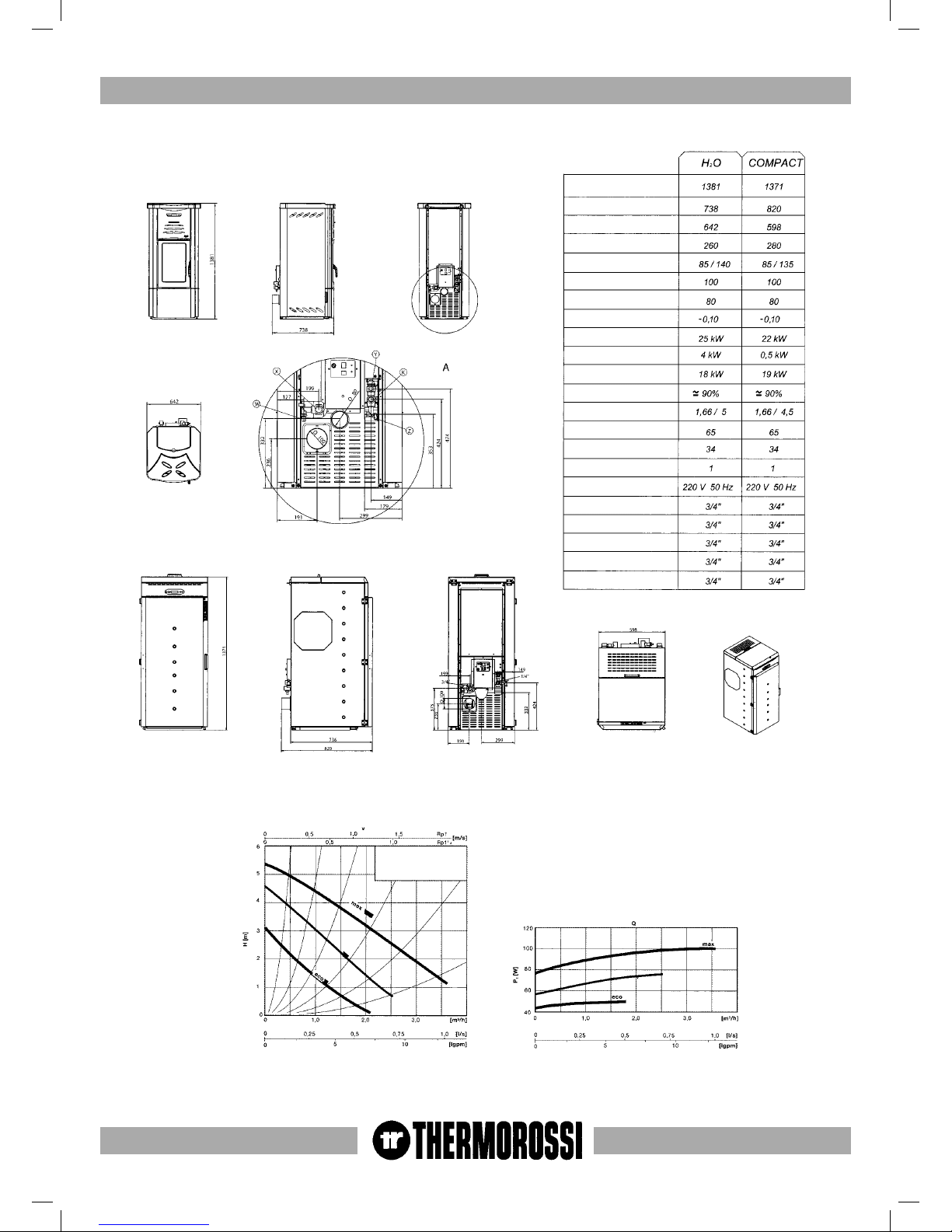
2.1 TECHNICAL DATA
CHARACTERISTIC CURVE OF SINGLE-PHASE PUMP
Height (mm)
Depth (mm)
Width (mm)
Weight (kg)
Smoke Temp. min – max (C)
ø smoke outlet tube (mm)
ø combustion air tube (mm)
Minimum draft (mbar)
Heat efficiency (kW)
Air output power (kW)
Water output power (kW)
Efficiency
Min/max consumption (kg/h)
Tank capacity (kg)
Water content (l)
Working pressure (bar)
Electricity
X water return to plant
W boiler drain
K water delivery to plant
Y safety valve 3 bar
Z water replenish to plant
CHARACTERISTIC
CURVE OF
SINGLE-PHASE PUMP
Page 8

pag. 8
3. GENERAL DESCRIPTION
3.1 OPERATING TECHNOLOGY
Your heater/boiler has been built to fully satisfy all your heating and practical requirements. Top-grade components and
functions managed with microprocessor technology guarantee high reliability and optimal performance.
3.2 PELLETS
• The heater is fuelled by pellets, that is, cylinders of compressed sawdust; this allows you to fully enjoy the heat of the
flame without having to manually stoke the combustion.
• The pellets are cylinders of compressed sawdust having a 6 mm diameter and a maximum length of 20 mm.
They have a max moisture content of 8%; a thermal value of 4000/4500 Kcal/Kg and a density of 620-630 Kg/m
3
.
• Ordinary wood with a moisture content of 10-20% has a Lower Heating Value of 2500-3500 Kcal/Kg.
3.3 FEEDBOX
The feedbox is situated in the top part of the heater/boiler. The maximum load capacity is 65 kg.
We recommend emptying the container once a month and vacuuming the accumulated sawdust
The manufacturer recommends emptying the feed screw assembly and cleaning it with a vacuum
cleaner during the summer months and regularly once a month.
The use of fuel which does not comply with the description given above immediately voids the heater/
boiler warranty.
GENERAL DESCRIPTION
Page 9
pag. 9
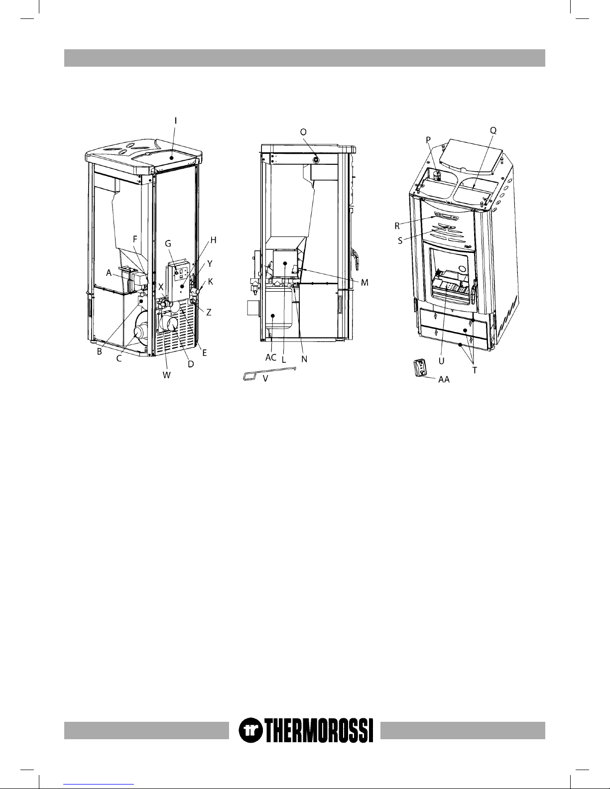
3.4 MAIN COMPONENTS OF THE H2O HEATER AND COMPACT BOILER
GENERAL DESCRIPTION
A: BRAZIER CLEANER MOTOR
B: SYSTEM CIRCULATING PUMP
C: SMOKE SUCTION UNIT
D: SMOKE OUTLET TUBE
E: COMBUSTION AIR EXHAUST TUBE
F: SMOKE SIDE PRESSURE SWITCH
G: SAFETY THERMOSTAT CALIBRATED AT 100°C
H: PELLET FEED MOTOR
I: PELLET TANK
L: ELECTRONIC POWER BOARD
M: PRESSURE TRANSDUCER
N: SPARK PLUG
O: SUMP FOR PTC HEATING SENSOR AND
THERMOSTAT BULB WITH RESET AT 100°C
P: AUTOMATIC RELIEF VALVE
Q: INSPECTION COVER FOR TUBE BUNDLE
R: CONTROL PANEL
S: SPIRAL TUBE SCRAPER LEVER
T: ASH PANS
U: PATENTED BURNER
V: RIDDLING TOOL
W: PLANT DRAIN GATE VALVE
X: WATER RETURN
K: WATER DELIVERY
Z: GATE VALVE FOR PLANT REFILL
Y: SAFETY VALVE 3 BAR
AA: ROOM TEMPERATURE THERMOSTAT
AC: 8 L EXPANSION TANK TO PROTECT BOILER
Page 10
pag. 1
INSTALLAZIONE
pag. 10
4. INSTALLATION
4.1 HEATER/BOILER LOCATION
CAUTION: Use trolleys to move the appliance and always keep it in a vertical position.
To unpack it, after having removed the wooden crate, remove the casing (in the reverse order than described
in par. 4.2)
Remove the screws from the base of the heater/boiler and shift the heater from the pallet.
Observe the general guidelines in paragraph 1.1 carefully. Above all, keep in mind that the floor in the room
where the appliance is to be installed will have to bear the weight of the heater. CAUTION: The room in
which the appliance is installed must be adequately ventilated (1300m3/h)
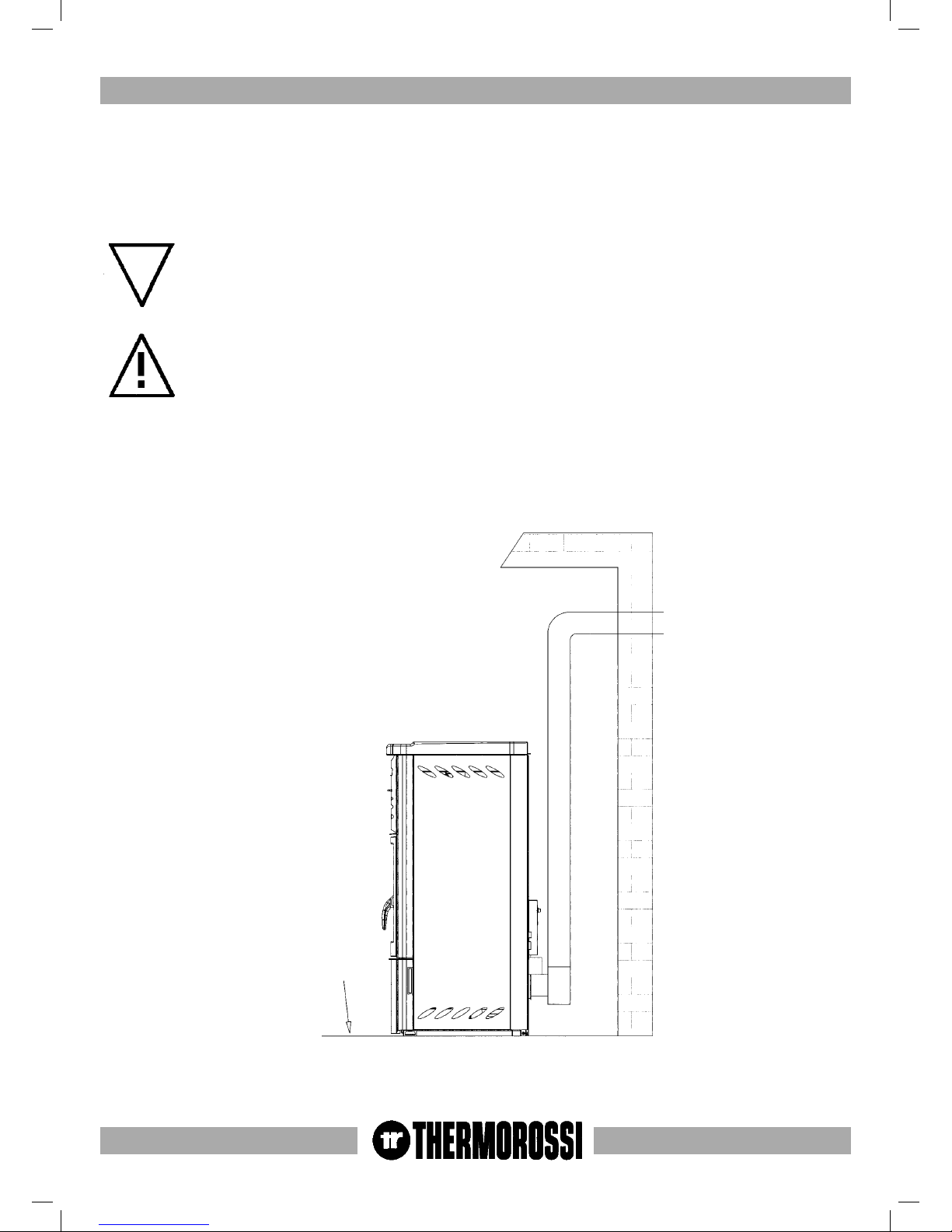
The appliance must be positioned at a minimum safe distance from walls and furnishings. This distance will
have to be increased considerably if the objects surrounding the appliance are inflammable (matchboarding,
furniture, curtains, picture frames, sofas, etc...). The recommended minimum distances are indicated in the
drawing below. In Italy there are no specific standards concerning this matter, consequently these indications
are simply recommendations which are non-binding as far as the manufacturer is concerned. The appliance
will have to stand on the mounting feet installed at its base, particularly on delicate floors.
450 mm if wood ceiling
250 mm if masonry ceiling
If installed on wood floor, use
a protective hearth pad
450 mm if wood wall
INSTALLATION
Page 11
pag. 1
INSTALLAZIONE
pag. 11
INSTALLATION
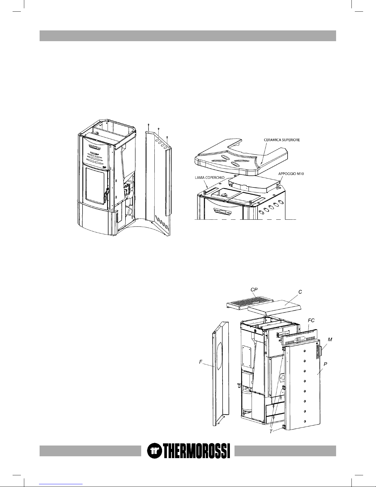
4.2.1 HOW TO MOUNT THE H2O HEATER CASING
Once the heater has been positioned and levelled by raising or lowering the mounting feet, and connected to the heating
system and the electrical system (see par. 4.5, 4.7, 4.8, 4.9, 4.10, 4.11), the next step is to mount the casing as illustrated in
the figure below:
- Firstly mount the 2 side panels by centring the bottom folds on the holes of the base and tightening the 2 top screws with
a screwdriver.
- Place the cover plate on the top and fasten using the M8 screws. Adjust the height of the M10 mounting elements then
place the ceramic top on top of them.
4.2.2 HOW TO MOUNT THE COMPACT BOILER CASING
Once the heater has been positioned and levelled by raising or lowering the mounting feet, and connected to the heating
system and the electrical system (see par. 4.5, 4.7, 4.8, 4.9, 4.10, 4.11), the next step is to mount the casing as illustrated in
the figure below:
- Firstly mount the 2 side panels (F) by centring the bottom folds on the holes of the base and tightening the 2 top screws
with a screwdriver.
- Then fix the forward top cover (C) to the sides.
- Then fix the front control panel (FC) to the sides.
- Then fix the door (P) to the left side with the hinges and
screws provided.
- Lastly fix the back top cover (CP) to the sides by fastening
the hinges of the cover with the screws provided.
If you prefer the door (P) can be mounted with the handle on
the left and the hinges on the right. Simply remove the handle
(M) from the door and fix it to the holes on the left side of the
door, remove the 3 hinges (T) and fix them to the right side
of the door. Similarly, remove the magnets with their lodgings
from the right side of the door and mount them on the left side
of the door.
Page 12

pag. 12
4.2.3 HOW TO INSTALL AN ADDITIONAL COMPACT BOILER TANK (OPTIONAL)
To increase the boilerʼs autonomy of operation it is possible to install one or two additional tanks at the sides of the boiler.
Each tank can hold up to 100 Kg of pellets.
Firstly unpack the tank then assemble it:
- Fasten the 4 telescopic legs (A) using the screws provided (screws TSP+ 8x50).
- Fasten the pellet chute (B) to the tank using the screws provided (screws TC+4.8x13).
- Mount the panel (C) by inserting the bottom folds on the holes of the tank, and then securing it using the screws
provided (screws TC+4.8x13).
- Similarly fasten the panel (E) using the screws provided (screws TC+4.8x13).
- Then mount the panel (D) by lining up the lower rectangular holes on the panel folds (E) and fastening them using the
screws provided (screws TC+4.8x13).
- The panels (D) and (E) can be mounted to the right or to the left of the pellet chute (B); if mounted on the right the
additional tank will have to be mounted to the right of the boiler.
- Fix the panel (G) by inserting the bottom folds on the mounting feet and securing them with the screws provided (screws
TC+4.8x13).
SCREW TC+4.8x13 (2pcs)
SCREW
TC+4.8x13
(2pcs)
SCREW TC+4.8x13 (4pcs)
SCREW TC+4.8x13 (2pcs)
SCREW TC+4.8x13 (2pcs)
SCREW TC+4.8x13 (2pcs)
SCREW
TSP+8x50+NUT (4pcs)
INSTALLATION
Page 13

pag. 13
4.2.2 HOW TO FIT THE ADDITIONAL TANK (OPTIONAL) WITH THE COMPACT BOILER
After having mounted the additional tank assemble the tank and boiler:
- Remove the octagonal portion of precut sheet metal from the side (F) of the boiler .
- Remove the cap (I) from the tank by undoing the 4 screws.
- Move the additional tank up against the boiler by adjusting the mounting feet (H) until the assembly is satisfactory.
- Proceed to fix the assembly using the screws previously removed from the cap (I).
4.3 HEATING FUNCTIONS OF H2O/COMPACT CONTROL PANEL
The control panel is managed by a microprocessor. The temperature detection system is controlled by a thermocouple.
The large display improves appliance management by making read-outs and functions promptly available. The main feature
of the panel is the all-automatic management of the boiler. The controls and displays are described below.
INSTALLATION
Page 14

pag. 14
INSTALLATION
1 - Appliance start up and shut down button. Press this button to position the appliance (6) on START or OFF. When it is
pressed repeatedly up to 5 LEDs (4) come on and the indicator A (4; automatic) is activated. The following texts could
appear on the display:
“ STOP” when the heater shuts off temporarily because it has reached the set temperature.
“ WORK “ when the work phase is active.
2 - Temperature setting button. Press this button to set the set point temperature for the appliance: the setting range is
between 65°C and 73°C settable by means of the adjusting button (2).
3 - Programming buttons. The + button is used to view the pressure inside the boiler body. A transducer detects the pressure
which is displayed for a few seconds after the + button is pressed once.
Press the - button when the machine is OFF to activate or deactivate the programming (see par. 4.4.3.)
4 - Combustion power indicator. The combustion power is indicated in this area of the display. These levels are activated
by pressing button
HEATER OFF
1 POWER LEVEL(The heater always remains at this power level)
2 POWER LEVELS (The heater always remains at this power level)
3 POWER LEVELS (The heater always remains at this power level)
4 POWER LEVELS (The heater always remains at this power level)
5 POWER LEVELS (The heater always remains at this power level)
AUTOMATIC ( The heater modulates the thermal value according to plant requirement)
(For further details see the next paragraph)
5 - Date and time
6 - This area of the display indicates the boiler operating phases:
WORK - work phase: the appliance displays the power by means of the indicator (4).
START - start up phase: during this phase (lasts approx. 20 minutes) the appliance is self-adjusted independently from
the preset power (4).
STOP - temporary shut off phase: if the cycle is in automatic or manual mode the temporary shut off temperature is 75
°C. The restart phase occurs at a temperature of 74°C
OFF - shut down phase. As soon as the OFF symbol appears the smoke suction unit functions for approx. 30 minutes
before the appliance goes into stand-by mode.
7 - This temperature value is set by means of button 2. If the appliance exceeds this value it automatically turns to the
minimum power in standby mode until the plant requires greater absorption.
8 - This symbol indicates that the plant circulating pump is operating. If it is displayed it indicates that the circulating pump
is operating (it is activated when the temperature in the boiler exceeds 61 °C, and if it is not displayed this indicates that
the plant circulating pump is not operating.
9 - This value is the temperature detected by the thermocouple.
Page 15

pag. 15
INSTALLATION
4.3.1 DESCRIPTION OF THE AUTOMATIC MODE CYCLE
When the letter A appears on the display it indicates that the Automatic cycle has been selected. In the Automatic cycle the
appliance expresses its maximum operating flexibility by optimizing the fuel consumption. If, for example, the temperature
is set (7) at 70 °C the five speed ratios will be automatically distributed between 61 and 70°C so that when the temperature
reaches 70°C the appliance will be running at the minimum power. The level at which the minimum is reached can be
changed by means of button (2). If the value of the button (2) is increased or reduced all the power steps will be redistributed
in the temperature scale.
Consequently, we recommend you find the appropriate level at which the SET POINT minimum is reached in order to
optimize the heat produced by your heater.
If, for example, the SET POINT is set at a high temperature such as 73°C the appliance will attempt to go to that level in
the shortest time possible by modulating the power as it approaches the set temperature. There is no point in setting high set
point temperatures when the conditions of the environment do not require them. With time and experience you will learn
which set points are best for your particular needs.
If the combustion power is not absorbed by the plant above 76 °C, the appliance will shut off temporarily and STOP appears
on the display (6). The heater starts up again at 74 °C.
4.3.2 DESCRIPTION OF THE MANUAL MODE CYCLE
When the plant is operating in manual mode the letter A disappears from the display. The power expressed in this cycle
remains constant independently from the power absorbed by the plant. The plant pump is always activated at anticondensation
temperatures, that is above 61 °C. In this case as well, it is possible to set a set point temperature above which the appliance
will run at minimum power. If an overly-high power level for plant absorption is set, above 75 °C the appliance will shut off
temporarily and the word STOP appears on the display (6). The heater will automatically restart at a temperature of 74°C.
Page 16

pag. 16
INSTALLATION
4.4 CONTROL, ADJUSTMENT AND PROGRAMMING FUNCTIONS OF THE H20/COMPACT
CONTROL PANEL
4.4.1 SETTING THE OPERATING PROGRAMS P1 AND P2
Your appliance is provided with an excellent operating program to enhance combustion efficiency. The particular
configuration of the burner keeps the area where the pellets drop and burn clean for many hours. However, if you wish to
keep the burner even cleaner simply select the P2 operating cycle which emits a larger quantity of air into the brazier. This
operating program accelerates the smoke exhaust even further and consequently when you select it you know there will be
a loss in combustion efficiency. The fuel consumption is not affected. Use the following procedure to select the P2 operating
cycle:
Switch off the appliance by turning the rear selector switch to “0”.
Press and hold down the button ( 2 )( see par 4.3), then re-power the appliance by turning the selector switch to 1.
The text P2 appears on the display to indicate that the cycle has been selected; at that point release the button (2).
The appliance will retain the P2 setting even if the electrical power supply is cut off.
To return to the P1 setting carry out the above operations, that is:
Switch off the appliance by turning the rear selector switch to “0”.
Press and hold down the button ( 2 ), then re-power the appliance by turning the selector switch to 1.
The text P1 appears on the display to indicate that the cycle has been selected; at that point release the button (2).
The appliance will retain the P1 setting even if the electrical power supply is cut off.
The consumption of the appliance remains the same for the two power levels P1 and P2.
4.4.2 SETTING THE TIME AND DATE
To access the current time and date setting menu the appliance must be in OFF mode. See the drawing below.
Hold down the button and press the button until the graphic image shown below appears on the display.
Press the button to set the current day (e.g. Monday). Then press the button to confirm. The following
graphic image will appear on the display:
Page 17

pag. 17
INSTALLATION
Press the button to set the current hour (e.g. 10). Then press the button to confirm.
The following graphic image will appear on the display:
Press the button to set the minutes (e.g. 10:35). Then press the button to confirm and quit the current time
and day setting menu. The following graphic image will appear on the display.
4.4.3 CONTROLLING THE PRESSURE OF THE WATER IN THE BOILER
The appliance is equipped with a pressure transducer for controlling the amount of water and pressure in the hydraulic
circuit.
To view the pressure inside the boiler press the button . The value of the steam pressure (expressed in bars) detected
by the sensor appears on the display for a few moments; see the figure illustrated below.
If the circuit pressure drops to values which are too low caused, for example, by fluid leaks from tubing or other areas the
pressure transducer detects that the pressure is too low and P H2O appears on the display. In this situation the appliance does
not feed pellets and the smoke exhaust works for a few minutes to discharge any remaining combustion products.
The alarm resets automatically if the pressure returns to a value above 0.3 bar.
The recommended pressure inside the boiler is 0.8 - 1 bar.
The pressure level must remain under 3 bar because if it goes higher than this threshold a safety valve calibrated at 3 bar is
activated and the water is drained out of the circuit (see hydraulic installation diagrams).
Page 18

pag. 18
INSTALLATION
4.4.4 WEEKLY PROGRAMMING
The H20 appliance and Compact boiler can be programmed for a week with up to 2 on-off cycles for each day from
Monday to Sunday. When the appliance is running in programmed mode ( symbol active) the appliance self-adjusts its
combustion power according to the automatic cycle (see par. 4.3.1) and according to the room temperature thermostat (see
par. 4.6).
To access the programming mode the appliance must be in OFF mode (see drawing below ).
Press and hold down the button and press the button until the following graphic image appears on the
display:
Press the button and/or the button to set the hour for the appliance to start up for the first time during the
day on Monday (e.g. 8.00 am). Then press the button to confirm. The following graphic image will appear on the
display:
Press and hold down the button and/or the button to set the minutes for the hour at which the appliance
should start up for the first time on Monday (e.g. 8:30). Now press the button to activate the programming mode
(symbol active).
Then press the button to confirm. The following graphic image appears on the display:
Page 19

pag. 19
INSTALLATION
Press the button and/or the button to set the hour for the appliance to stop for the first time during the day
on Monday (e.g. 11.00 am). Then press the button to confirm. The following graphic image will appear on the
display:
Press the button and/or the button to set the minutes next to the hour for the appliance to stop for the first
time during the day on Monday (e.g. 11.30 am). Then press the button to confirm. The following graphic image
will appear on the display:
Now press the button and activate the programming mode ( symbol indicates programming mode is active) for
the first on-off phase for Monday.
CAUTION: for the programming to be active the 2 symbols must appear. Then press the button to quit the
menu relevant to the first programming for Monday.
The following graphic image will appear on the display:
If you do not enter a value next to OFF1 11.30, the OFF value from another subsequent day will be adopted and the
symbol activated.
The second on-off programming for Monday must be made in the same way as the first on-off programming for Monday.
Program the appliance on-off settings for each day of the week following this procedure.
If you do not want to program the appliance for a particular day, such as for example Thursday, then the display for the two
programmings for Thursday should appear as shown below; that is the symbols should not appear on the display.
Page 20

pag. 20
It is possible to activate or deactivate the programming for the entire week by pressing the button when the heater
is in OFF mode. Press this button to activate ( symbol appears) or deactivate ( symbol does not appear) the
programming. If the programming is activated the display in OFF mode indicates:
INSTALLATION
Page 21

pag. 21
4.5 H2O/COMPACT POWER BOARD DIAGRAM
Receiver
board
Smoke exhaust
Code selector for room
temperature thermostat
managed by radio waves
Control panel
Burner motor
Thermostat
100°C reset
Pellet feed motor
Heating element
Common
n.o. (normally open)
Motorised boiler tube SV
valve circulating pump
Plant circulating
pump
Additional circulating
pump
220-240 V
50 Hz
Boiler PTC
sensor
Smoke side
pressure switch
Radio receiver
antenna
Pressure
transducer
Fuse 3.15 A
Fuse 3.15 A
Fuse 1A
3 way motorised valve
must have spring return
4.6 H20/COMPACT ROOM TEMPERATURE THERMOSTAT
The room temperature thermostat is supplied with the appliance. The display A indicates
the temperature set by the user. This value can be changed by means of the controls B and
C. The display D indicates the room temperature detected by the thermostat. The signal is
transmitted by radio waves. The unit is powered by the 220-12V transformer supplied with
the heater. The thermostat may be affixed to a wall (see drawing on the right) or in any
other area as long as it is installed approximately 1.5 metres from the floor, away from heat
sources, windows and any other object which could affect the correct room temperature
value. The thermostat should be installed no further than 10 metres from the appliance
for normal operation. Clean the surfaces thoroughly before fixing the velcro to the them.
The room temperature thermostat detects the temperature and updates it roughly every 30
seconds.
When the room temperature reaches the temperature
set on the thermostat the appliance displays a
blinking black bar indicating the minimum power
level. At that point the power increase operations are disabled. In this phase the
appliance shuts off (according to the manual or automatic cycle previously selected)
if the set point temperature of 76°C is reached in the boiler.
If the power supply to the thermostat or the transmission is cut off, normal operation
restarts from the control panel after 5 minutes.
INSTALLATION
Page 22

pag. 22
INSTALLATION
It is furthermore necessary to place the room temperature thermostat at a
maximum of 10 metres from the appliance as if the distance is too great and
there are too many walls located between the room temperature thermostat
and the appliance, this can affect the functioning of the thermostat.
In order for the room temperature thermostat to function correctly it is
important for the “code system” of both the thermostat and the power board
to be set with the same combination. To access the boardʼs “code selection
system” firstly disconnect the power supply, then remove the applianceʼs left
side panel and remove the 2 screws from the power board cover (par. 3.4).
To access the “code selection system” of the room temperature thermostat,
firstly disconnect the power supply, then undo the only 2 screws present on
the thermostat and open the 2 half bearings (see figure above). Our products
are set with a standard code. To change the transmission code simply act on
the selector switch indicated on the top left to change the combination on both
panels, that is the control board and the room temperature thermostat.
4.7 H2O HEATER/COMPACT HYDRAULIC DIAGRAM
1 Circulating pump
2 Smoke pressure switch
3 Smoke exhaust
4 Automatic air relief valve
5 Boiler PTC sensor
6 Thermostat bulb 100 °C reset
7 Water pressure transducer
8 Expansion tank closed
W Plant drain gate valve
X Water return to plant
K Water delivery to plant
Z Plant replenish gate valve
Y Safety valve 3 bar
CAUTION: FOR THE DELIVERY, RETURN, REFILL AND DRAIN CONNECTIONS USE FLEXIBLE
TUBES WHICH ARE AT LEAST 70 CENTIMETRES LONG, IN ORDER TO FACILITATE MOVING
THE HEATER FOR MAINTENANCE.
CAUTION: IT IS ADVISABLE TO FILL THE SEAT (5 AND 6) WITH LUBRICATING OIL. THIS
WILL GUARANTEE OPTIMAL, FAST DETECTION OF THE TEMPERATURE IN THE BOILER BY
MEANS OF THE BOILER PTC SENSOR AND THE THERMOSTAT BULB WITH 100°C RESET.
Page 23

pag. 23
INSTALLATION
4.8 EXAMPLE OF HYDRAULIC DIAGRAM FOR H2O HEATER/COMPACT ONLY HEATING
4.8 EXAMPLE OF HYDRAULIC DIAGRAM FOR H2O HEATER/COMPACT ONLY HEATING
A: Heating system delivery
R: Heating system return
S: gate valve
VNR: non-return valve
VEC: expansion tank closed to protect system
VR: pressure reduction valve
Drain
From water supply
system for replenishment
A: Heating system delivery
R: Heating system return
S: gate valve
VNR: non-return valve
VEC: expansion tank closed to protect system
VR: pressure reduction valve
From water supply
system for replenishment
Drain
CAUTION: The temperature of the water in the boiler tube is not adjustable in this case and it depends on the temperature
of the water delivery to the plant, that is the SET POINT temperature.
Boiler tube with
interspace
Page 24

pag. 24
INSTALLATION
4.10 EXAMPLE OF HYDRAULIC DIAGRAM FOR H
2
0 HEATER/COMPACT WITH BOILER TUBE COILS
4.11 EXAMPLE OF HYDRAULIC DIAGRAM OF H20/COMPACT WITH INSTANT HOT WATER
FOR DOMESTIC USE.
The temperature of the boiler tube depends on the temperature set on the boiler tube thermostat.
The contacts to be used to connect the thermostat are terminals 14,15 described in paragraph 4.5. The 3 way motorised valve
must be powered by terminals 16-17 described in paragraph 4.5.
A: Heating system delivery
R: Heating system return
S: gate valve
VNR: non-return valve
VEC: expansion tank closed to protect system
VM3V: 3-way motor-operated valve with spring return
VR: pressure reduction valve
From water supply
system for replenishment
Drain
A: Heating system delivery
R: Heating system return
S: gate valve
VNR: non-return valve
VEC: expansion tank closed to protect system
PCB: boiler tube circulating pump
VM3V: 3-way motor-operated valve
TB: boiler tube thermostat
VR: pressure reduction valve
F: flow switch
VM: mixing valve
SF: automatic relief
Drain
Salts for
resins
Filter
From water
supply system
Softener
METERING DEVICE FOR
POLYPHOSPHATES
If a flow switch is installed, the three way valve can be connected to either terminal 16 or 17 described in paragraph 4.5. or
powered independently. The valve is activated by the detection of the water flow caused by the release of hot water.
Page 25

pag. 25
5. USE OF THE HEATER/BOILER
5.1 SWITCHING ON THE H20 HEATER/COMPACT BOILER
Before using the appliance check that all the movable parts are in place; also remove any labels and
stickers from the glass to avoid having permanent traces remain on the surfaces.
Ensure that the electrical and hydraulic connections have been made perfectly.
Then carry out the following operations:
- Check that the hydraulic plant has been made correctly, and that the expansion
tank is sufficiently large to guarantee maximum safety. Remember that expansion
is calculated as 6 % of the total volume contained in the plant. Any damage to the
plant and/or the appliance shall not be considered as covered by the warranty. The
installation of the expansion tank in the appliance does not guarantee adequate
protection from the thermal expansion of the water in the plant.
- Connect the electrical power supply to the appliance and turn the rear switch to “1”.
- Fill up the plant by opening the cock Z (figure on right).
- During the replenishment phase do not apply over-pressure to the appliance: max
pressure 1 bar. Read the pressure as explained in paragraph 4.4.3.
- The water filling phase must take place simultaneously with the discharge of air.
Perform the bleeding operation by means of a screwdriver (to accelerate the plant
fill-up times) or a punch on valve 4 (figure on right)
- Connect the smoke outlet to the appliance: we recommend against using aluminium
tubes. Always use sealing gaskets. More details are given in paragraph 8.2 of this
use and maintenance booklet.
- Load the pellets into the tank.
- Press the “A” button to start the start up cycle, which is confirmed by the word
START appearing on the display. Press the same button once again to set the
combustion power level. Press the “B” button to adjust the set point temperature
for the water in the boiler (see par. 4.3). In the 20 minutes required for start up any
thermal power level set by the user is ignored in order to meet the correct loading
and suction values which have been preset by the Manufacturer. The pellets do
not drop into the burner the first time the appliance is switched on during the initial phase because the screw feeder is
empty.. As soon as the first few pellets drop into the brazier it could turn off and reset all the black bars. The word OFF
must appear on the display. At this point you can restart the start up phase knowing that it will be successful.
- Check the pressure inside the appliance once again and if required, bleed air bubbles from the special valve.
CAUTION: The start up phase lasts 20 minutes.
CAUTION: The system circulating pump starts as soon as the temperature in the boiler reaches 61°C.
CAUTION: If the appliance does not start up correctly check that the brazier and heating element are clean.
It is extremely important to ensure that the conduit for the heating element is clean; there must be
no scale or dust accumulations. Clean using a strong vacuum cleaner.
USE OF THE HEATER/BOILER
Page 26

pag. 26
USE OF THE HEATER/BOILER
5.2 ADJUSTING THE COMBUSTION OF THE H2O HEATER/ COMPACT BOILER
The thermal value is adjusted by means of the 2 buttons “A” and “B” indicated in the figure in the previous paragraph.
5.2.1 Manual adjustment of the combustion (see par. 4.3.2)
5.2.2 Automatic adjustment of the combustion (see par. 4.3.1)
CAUTION: The manufacturer declines all responsibility for the life of the electrical heating element
if subjected to an excessive number of start ups.
Consequently, it is advisable to set the correct power level to avoid such a hazard.
5.3 ADJUSTING THE ROOM THERMOSTAT H2O/COMPACT
See paragraph 4.6 for details on using the thermostat.
6. ADDITIONAL ROOM TEMPERATURE THERMOSTAT
AND CHRONOTHERMOSTAT
Two connectors are installed at the back of the heater near the power socket. These refer to two operating modes which can
also function simultaneously:
- With the additional room temperature thermostat
- With the chronothermostat.
CAUTION DANGER: the contacts on the jacks must
never be powered with 220 V power contacts
6.1 ADDITIONAL ROOM TEMPERATURE THERMOSTAT (NOT SUPPLIED)
An additional room temperature thermostat may be installed, connected to the back of the appliance by means of a jack
inserted into the socket marked «TERMOSTATO/THERMOSTAT». This is a stereo-type jack, and it is supplied with
the heater; the thermostat must be connected to the “X” and “Y” contacts (see figure). The two tin-coated wires must be
connected on the room temperature thermostats to the N.C. terminals (contact normally closed).
The operating principle is as follows: if during operation the thermostat contact closes, the combustion power turns
automatically to the minimum power level. The situation is indicated by the blinking of the 1st power bar on the display.
It is possible to install it together with the room temperature thermostat supplied with the appliance.
CAUTION: The contacts to be used for the connection to the additional room temperature thermostat
must be the N.C. type mod. “Perry “ contacts 1-2
6.2 ADDITIONAL CHRONOTHERMOSTAT (NOT SUPPLIED)
As an alternative to the additional room temperature thermostat it is possible to install an additional chronothermostat, by
connecting it to the back of the appliance, by means of a jack inserted into the socket marked «CRONOTERMOSTATO/
CHRONOTHERMOSTAT». This is a stereo-type jack, and it is supplied with the heater. The chronothermostat must be
connected to the “X” and “Y” contacts (see figure above). The operating principle is as follows: when the contact closes the
appliance starts up in automatic mode whereas when the contact is opened the appliance shuts off. An N.O. contact must
be used, that is normally open. When the chronothermostat is active, the appliance cannot be switched off except by means
of the additional chronothermostat.
CAUTION: N.O. type contacts must be used for the connection to the additional chronothermostat.
Contact 1 - 3 mod. “Perry “.
Page 27

pag. 27
7. CLEANING AND MAINTENANCE
CLEANING AND MAINTENANCE
7.1 FOREWORD
Before beginning any operation ensure that the appliance is in the “OFF” mode, by disconnecting the electrical
power plug. Your appliance does not require any special maintenance; keep to the simple, basic but frequent
general control and cleaning operations. This will guarantee good operation and optimal performance of your
appliance.
7.2 CLEANING AND MAINTAINING OF THE HEATER/BOILER
• EVERY week and more often if necessary empty
ash pan C1.
• EVERY week and more often if necessary empty
ash pan C2.
• EVERY 2 weeks clean the smoke outlet “T” at the
appliance mouthpiece
• EVERY month and more often if necessary empty
ash pan C3. To access the ash pans remove the cover
“F” by means of the two black fold-away handles
and pull outwards (for the H20). To access the boiler
ash pans simply open the door
• EVERY 2 - 3 days use the poker provided to push
and pull the tube scraper 4-5 times (fig. following
page; to access the riddling tool in the boiler simply
open the door).
• EVERY 1 - 2 days and more often if necessary clean
the burner.
• EVERY 1 - 2 days and more often if necessary
clean the glass.
• EVERY month vacuum clean, with the tank empty,
the dust deposits on the bottom of the tank.
CAUTION: To guarantee correct and optimal combustion it is very important to ensure
that ash pans C1, C2, and C3 are closed correctly and hermetically after maintenance. Do
not open compartments C1, C2, C3 during operation to avoid tripping the smoke exhaust
pressure switch, alarm PGAS
• WHEN THE WINTER PERIOD IS OVER AND WHENEVER IT IS NECESSARY we recommend cleaning the
bottom of the firebox and ash pans of the H2O appliance, using brushes and vacuum cleaner. At the end of each season also
clean out the tube bundle chamber by removing the inspection cover as shown in the figure on the next page.
• AT LEAST ONCE A MONTH we recommend checking the smoke outlet to ensure that it is free from fly ash, especially
in the initial sections which could have a smaller section.
• AT LEAST TWICE A YEAR clean the flue outlet. If there are any horizontal sections, check for ash and soot deposits
and remove them before they clog the tube.
Page 28

pag. 28
CLEANING AND MAINTENANCE
A vacuum cleaner simplifies the ash
removal process. Clean the glass with a
damp cloth or a damp ball of newspaper
dipped in ash and wipe the glass until it
is perfectly clean. Do not clean the glass
while the appliance is in operation.
CAUTION: a daily deposit of soot and
combustion residues on the glass is quite
normal.
To clean the H2O heat exchanger tubes:
- remove ceramic 1
- remove cover 2
- remove wing nuts 3
- remove cover 4
To clean the boiler exchanger tubes:
- remove cover 1
- remove wing nuts 3
- remove cover 2
Page 29

pag. 29
CLEANING AND MAINTENANCE
7.3 PATENDED SELF-CLEANING BURNER (NR. VI2004A000014)
The H2O heater/Compact boiler is fitted with a
state of the art patented burner which manages
to guarantee high performance with optimal
automatic cleanliness of the burner due to the
special applied technology. The combustion
generates the division of the flame into 2 fronts:
this guarantees optimal use of the firebox walls,
which have never been used to advantage in other
pellet appliances. Manual cleaning of the heater
is reduced to a minimum.
Disassemble procedure:
- Remove blade 1 .
- Open the closure springs 6.
- Move away chutes 2 and 3 .
- Remove the arm 4 and bearing 5.
- Remove the screws (8) and pull out the brazier
To reassemble, reverse the above process.
In the OFF mode the left-right movement of
the cast iron blade 4 for cleaning the brazier
is set at roughly 10 mins.
It is normal to find partially burned embers on
the sides of the burner.
1 - flame deflector blade
2 - cast iron rear burner chute
3 - cast iron front burner chute
4 - catalyst paddle
5 - bearing for catalyst paddle
6 - closure spring
7 - cast iron burner
8 - screw TCEI M8
8. SMOKE VENT AND COMBUSTION AIR SUCTION
Because of frequent accidents caused by poor functioning of the smoke outlets in normal houses, we have prepared the
following paragraph to assist the installer in checking all the parts related to eliminating smoke produced by the combustion
process. The smoke outlet must comply with UNI 7129/92 in observance of the following reference values.
8.1 VENTILATION OF THE ROOMS
• The room where the heater is installed must have a good air flow to guarantee secondary air for the appliance for the
combustion process and for ventilation of the room. The natural air flow occurs directly through permanent apertures to
the outside made in the walls of the room, or by means of single or multiple ventilation ducting.
The ventilating air must come from outside and if possible, away from sources of pollution. Indirect ventilation is also
allowed by taking in air from rooms adjacent the one where the heater is installed taking into account all the warnings and
limitations specified below.
• The apertures in the walls must comply with the following requirements:
- have an unobstructed section of at least 6 cm2 for each Kw of installed thermal power, with a minimum limit
of 100cm2;
- be made in such a way that the vent openings, both on the inside and outside of the wall, cannot be obstructed;
- be protected with grills or similar systems in order not to reduce the section described above;
- be situated at floor-level.
Page 30

pag. 30
SMOKE VENT AND COMBUSTION AIR SUCTION
• Air used for combustion is sucked in through a tube installed at the back of the appliance. It has a diameter of 80 mm.
• The air flow can also be obtained from an adjacent room as long as:
- the adjacent room is equipped with direct ventilation in compliance with the points described above;
- in the room to be ventilated the installed appliances are only connected to one flue outlet;
- the adjacent room is not used as a bedroom or a common area of the building;
- the adjacent room is not a room with a fire hazard, such as storage sheds, garages, combustible material store rooms, etc...;
- the adjacent room does not become a vacuum compared to the room to be ventilated due to an opposite draught effect;
- the air flow from the adjacent room to the room to be ventilated is unobstructed through the permanent apertures having
an overall net section of no less than that indicated above. These apertures can be obtained by enlarging the space between
the door and the floor.
This chapter is not intended to replace UNI 7129/92 to which it refers. The qualified installer must
in any case be fully aware of this standard and its amending versions.
8.1.1 COMBUSTION AIR SUCTION
The air required for combustion can be taken from the room
in which the heater is installed. However, the room in which
it is installed must be sufficiently ventilated (1300 m3/h) (see
par. 4.1).
If you prefer to use air directly from outside simply follow the
diagram illustrated on the right.
- Remove the 2 self-tapping screws
- Remove the cover
- Move the suction tube to the limits given on the right.
- Be protected with grills or similar systems in order not to
reduce the section described above;
- Be situated at floor-level.
Back
Tube Ø 80
Max. 1 mt.
Wall
Install a 90° elbow externally as
protection against the wind
Cap
Page 31

page 31
SMOKE VENT AND COMBUSTION AIR SUCTION
8.2 SMOKE OUTLET
The smoke outlet shown in the following figures is the best solution to ensure the discharge of smoke even when the fan
is not operational, such as for example if there is an electrical power failure. A minimum drop of 1.5 metres is required
between the T terminal on the outside of the building and the outlet at the back of the appliance, to ensure that residual
combustion smoke is discharged in the case described above (Otherwise the residues would stagnate inside the firebox and
be discharged out to the free atmosphere).
The figures below illustrate the best solution for discharging the smoke out through the roof or into the flue outlet. If you
opt to discharge the smoke out through the roof it is important to operate as shown in the figure below on the left. The
smoke outlet tubes, given the low temperature of the gases, must be insulated. We recommend installing a “T” condensation
collector. Insert a union tee with inspection cap, connecting brackets suitable for the height of the flue outlet, flashing that
crosses the roof and chimney cap to protect against bad weather conditions. If you decide to use a classic masonry outlet
see the diagram below on the right. A union tee with inspection cap and suitable supporting brackets are required. If the
flue outlet is too big we recommend inserting a stainless steel or porcelain-coated steel tube with a diameter not exceeding
150mm. Seal area where the inlet and outlet part of the smoke exhaust meets the wall.
It is strictly forbidden to apply mesh to the end of the outlet tube , as it
could cause the appliance to malfunction. If the smoke tube is installed
in a fixed position it is advisable to provide inspection openings for
clean-out purposes especially in the horizontal sections. See the
diagram. These openings are essential to allow for the removal
of ash and unburned products which tend to accumulate along the
discharge path. The appliance functions with the firebox in a vacuum,
while the discharge of smoke to the flue outlet has a slight pressure,
consequently it is imperative to ensure that the discharge system is
hermetically sealed. The smoke discharge tube must be made from
suitable materials such as for example:
porcelain-coated steel tubes, and the various fittings sealed with red
silicone (resistant to 350°C). The outer casing of the tube must be
made with insulating material (mineral wool, ceramic fiber) or use
pre-insulated tubing.
It must be possible to inspect and remove all the smoke tube sections for clean-out purposes.
CAUTION: IF THE SMOKE FLUE IS NOT SUFFICIENTLY INSULATED AND/OR IT IS TOO LONG
IT COULD GENERATE CONDENSATION: IT IS ADVISABLE TO INSTALL A CONDENSATION
OUTLET NEAR THE APPLIANCE OUTLET.
Rain protection
Cover slab
Hermetic sheet
steel
Inspection
Inspection
External
Internal
Page 32

page 32
INFORMATION FOR THE SKILLED TECHNICIAN
9. INFORMATION FOR THE SKILLED TECHNICIAN
9.1 MAIN COMPONENTS AND THEIR OPERATION
SAFETY THERMOSTAT WITH MANUAL RESET: if the temperature exceeds 100°C the pellet feed screw is shut off.
A red light at the back of the appliance comes on. Once the reasons for the appliance exceeding the upper temperature limit
have been discovered and solved the heater can be reactivated by unscrewing the plastic cover of the thermostat installed
on the back and pressing the button (the temperature of the boiler must be below 73°C).
SAFETY VALVE 3/4” CALIBRATED AT 3 BAR: once the calibrated pressure is reached, the valve opens and discharges
to the free atmosphere (we recommend connecting this valve to an outlet to prevent damage to the material around the
appliance if it is activated) to prevent the pressure in the system from reaching dangerous levels for the generator and the
components of the system. If the valve is activated check and solve the problems which led to the overpressure.
EXPANSION TANK 8 LITRES: This is a safety device installed in the appliance which is used to compensate for the
increased volume of the water in the boiler due to the increase in temperature in the boiler .
SMOKE PRESSURE SWITCH: This is a safety device which, if necessary, shuts down the feed screw motor. The
main reason for the tripping of the pressure switch is the obstruction of the smoke flue or the smoke discharge tube. For
this reason it is strictly prohibited to install a mesh at the end of the tube. When the mesh clogs up it creates a plug which
activates the pressure switch which in turn, shuts off the fuel feed.
SMOKE EXHAUST: This is activated when the start up signal is given. In the first two minutes it «washes» the smoke
discharge tube, that is, it functions at maximum working rate. Once this time has elapsed it self-adjusts to the optimal
speed. To allow for the evacuation of the smoke and for greater safety of the system, the exhaust continues to operate for
approximately 20 minutes from the time the appliance is switched off.
SYSTEM CIRCULATING PLANT: This is a device which makes it possible to convey the hot water produced by the
appliance to the radiators, boiler tubes .....
When it is activated the symbol indicated in paragraph 4.3 appears on the display.
BURNER CLEANING MOTOR: This device makes it possible to create, inside the burner, a continual movement of the
pellets in combustion and a subsequent self-cleaning of the burner.
GLOW PLUG: is activated in the START phase. Heats the air to 800°C, which assist the first combustion of the pellets
present in the brazier.
LOADING MOTOR: This is activated at regular on/off intervals controlled by a microprocessor. The functionality of this
motor is reduced if:
-the motorʼs overload relay is tripped.
-the pressure switch is activated due to obstruction of the smoke discharge tube .
-end of pellet load.
-appliance switched off intentionally
PRESSURE TRANSDUCER: This device detects the water pressure in the system. The value can be checked by acting
on the control panel as indicated in paragraph 4.4.2.
AUTOMATIC RELIEF VALVE: This valve eliminates, without the need for manual action, the residues from the air
inside the appliance thereby preventing:
-corrosive processes due to presence of oxygen.
- noise generated by the flow of air in the tubes.
-air pockets located in the heating bodies.
-cavitation in the circulating pumps.
Page 33

page 33
9.2 TROUBLESHOOTING
9.3 USEFUL ADVICE FOR INSTALLATION AND OPERATION
Useful advice:
1 - The appliance must never be deliberately disconnected from the electric power supply. Whenever the appliance is
deliberately disconnected from the electric power supply smoke could be emitted into the room and be a hazard.
Similarly never switch off the heater by suddenly cutting off the electric power supply.
2 - Do not install the appliance with horizontal wall outlets only: evacuation of the combustion products must be guaranteed
in a natural manner.
3 - Do not install the appliance with horizontal sections only: the wall could be exposed to high wind conditions and the
heater could shut down due to back draft.
4 - Operate the appliance at maximum for 3 hours for a complete drying and baking of the silicates contained in the
enamel which covers the body of the heater.
5 - Do not install a grill or outlet terminal which could restrain the flow of the combustion gases: this could affect the
dynamic gas to the point where it would not allow the pellets to burn correctly.
6 - Read this instruction booklet.
7 - Keep the appliance clean and check the burner as described in this manual.
8 - Clean the smoke outlet regularly.
9 - Use top quality pellets: by saving 20 cents a bag you heat up to 50% less.
10 - Maximum useable lengths of smoke exhaust tubes:
Painted aluminized steel tubes (1.5 mm minimum thickness), Aisi 316 stainless steel tubes or 0.5 mm enamelled tubes
may be used.
Legally compliant smooth internal double-walled flexible stainless steel tubing with male-female collar couplings can
also be used. – Minimum vertical length 2 m – Maximum vertical length 8 m
Length with minimum slope of 5 % 0.5 m – Maximum number of elbows at least 0.5 m apart: 3
Pellet tank is empty
Foreign body such as nail, nylon, piece
of wood on the feeder screw on the
bottom of the tank
Outlet terminal clogged because a grill or
terminal has been inserted which prevents
the free passage of smoke
Smoke exhaust not free, or with terminal that
obstructs the passage of smoke
Sudden gust of wind which has made the
appliance go into safety mode
“PGAS” appears on the front control panel
Occurs at the first start up as the silicone
paint of the appliance is baking
Delayed ignition feed screw is empty
and in the ignition phase the boiler
temperature did not reach 30°C
Burner is dirty
The smoke exhaust is not sealed correctly
No cause
The tank is empty
Fill up the tank
Remove the foreign body
Remove the terminal and replace it with a
more suitable one
Remove the terminal and replace it with a
suitable terminal. Check the smoke exhaust
as it could be dirty or clogged
Switch the power supply to the appliance
off then back on again
Check the smoke exhaust as it could be
dirty or clogged
Run the appliance at full capacity for 10
hours to complete the baking process
Fill up the tank
Clean the burner on a more frequent basis
Check that gaskets have been installed
on the exhaust tubes
Clean the glass more often
Empty the burner and fill up the tank
The appliance accumulates pellets
in the brazier during operation
Pellets do not drop into the burner
The appliance smokes
“no temp resist” appears
on the display
The glass is covered in black soot
“Pellets finished clean the burner”
appears on the display
problem cause solution
INSTALLATION
Page 34

page 34
NOTES
Page 35

page 35
NOTES
Page 36

36011 Arsiero (VI) - Via Grumolo, 4 Z.I. - Tel. 0445.741310 (5 l.r.a.) - Fax 0445.741657
Web Site: www.thermorossi.com
Print: Peruzzo Industrie Grafiche S.p.A. - Padovacod. 06.011 - 04/2006
 Loading...