

Page 1

HEATING TECHNOLOGY AND INNOVATION
36011 Arsiero (VI) ITALY - V ia Grumolo, 4 - www .thermorossi.com
INST ALLATION, USE AND MAINTENANCE GUIDE
ECOTHERM 5000
Page 2

pg. 2
C O N T E N T SC O N T E N T S
C O N T E N T SC O N T E N T S
C O N T E N T S
DECLARATION OF CONFORMITY
1. INTRODUCTION .................................................................................................................................................................................
1.1 General guidelines .............................................................................................................................................................
1.2 Safety guidelines ................................................................................................................................................................
1.3 Standards and recommendations .....................................................................................................................................
1.4 Transportation and storage................................................................................................................................................
2. TECHNICAL CHARACTERISTICS ....................................................................................................................................................
3. GENERAL DESCRIPTION..................................................................................................................................................................
3.1 Operating technology .........................................................................................................................................................
3.2 Pellets .................................................................................................................................................................................
3.3 The feedbox ........................................................................................................................................................................
4. INSTALLATION ..................................................................................................................................................................................
4.1 Heater location ...................................................................................................................................................................
4.1.1 Installation of metalcolor casing .......................................................................................................................................
4.1.2 Installation of ceramic casing ...........................................................................................................................................
5 . DESCRIPTION OF CONTROLS .....................................................................................................................................................
5.1 Description of control panel and heater rear panel..............................................................................................................
5.2 Day and time setting .............................................................................................................................................................
5.3 ON/OFF Programming. ........................................................................................................................................................
5.4 Operating level setting .........................................................................................................................................................
6 . USE OF THE HEATER ...........................................................................................................................................................................
6.1 Switching on the heater ......................................................................................................................................................
6.2 Adjusting the heater’s combustion ...................................................................................................................................
6.3 Infrared remote control. .....................................................................................................................................................
6.4 Operation of white thermocomfort handheld radio control (optional) ..............................................................................
6.5 Filter ....................................................................................................................................................................................
6.6 Channelling .........................................................................................................................................................................
7 . ADDITIONAL ROOM TEMPERATURE THERMOSTAT (not supplied) ADDITIONAL CHRONOTHERMOSTAT (not supplied)
7.1 Operating with the additional room temperature thermostat (not supplied ) ..................................................................
7.2 Operating with the additional chronothermostat (not supplied) ......................................................................................
8. CLEANING AND MAINTENANCE ..................................................................................................................................................
8.1 Foreword .............................................................................................................................................................................
8.2 Cleaning and maintaining the heater ................................................................................................................................
8.3 Charging the battery of the handheld radio control. .........................................................................................................
8.4 Replacing the battery in the remote control .....................................................................................................................
8.5 Replacing the buffer battery of the control panel .............................................................................................................
9. SMOKE EXHAUST PIPE.....................................................................................................................................................................
9.1 Ventilation of the rooms .....................................................................................................................................................
9.2 Smoke outlet .......................................................................................................................................................................
10. ALARMS ............................................................................................................................................................................................
11. ELECTRICAL WIRING .....................................................................................................................................................................
12. INFORMATION FOR THE SKILLED TECHNICIAN.............................................................................................................................
12.1 Main components and their operation ...............................................................................................................................
12.2 Useful advice for installation and operation .....................................................................................................................
12.3 Troubleshooting cause-solution ........................................................................................................................................
13 SPARE PARTS ..................................................................................................................................................................................
Page 3
pg. 3
THERMOROSSI S.p.A.
Via Grumolo. 4
36011 ARSIERO
tel. 0445.741310
fax 0445.741657
"CE" DECLARA TION OF CONFORMITY
In accordance with the following directives:
European Directive 73/23/EEC and its amending directive 93/68/EEC
89/336/EEC and its amending directives 93/68/EEC
92/31/EEC
93/97/EEC
Thermorossi S.p.A., Via Grumolo 4 - ARSIERO (VI), declares that the heaters of the ECOTHERM series have been designed and manufactured
in compliance with the safety requirements of the standards for EC marking.
This declaration refers to the entire range of the specified series.
Ecotherm 5000 complies with EN 14785: 2006.
ARSIERO, 3 May 2010 THERMOROSSI S.p.A.
11
11
1
INTRODUCTIONINTRODUCTION
INTRODUCTIONINTRODUCTION
INTRODUCTION
1.11.1
1.11.1
1.1
GENERAL GUIDELINESGENERAL GUIDELINES
GENERAL GUIDELINESGENERAL GUIDELINES
GENERAL GUIDELINES
This installation, use and maintenance guide is an integral and essential part of the product and must be kept by the user . Before commencing with
the installation, use and maintenance of the product, carefully read all the instructions contained in this booklet. At the time of installation of the
appliance all local regulations, including those that refer to national and European regulations, must be observed. The Manufacturer recommends
carrying out all the maintenance operations described in this manual.
This appliance must only be used as intended by the manufacturer. Any other use is considered incorrect and therefore hazardous; consequently,
the user shall be totally liable for the product if used improperly. Installation, maintenance and repairs must be carried out by personnel with
professional qualifications and in compliance with current regulatory standards and in accordance with the instructions of the manufacturer of
the appliance. Use only original spare parts.
Incorrect installation or poor maintenance could injure or damage people, animals or things; in this case the manufacturer shall be relieved of all
responsibility. Before commencing any cleaning or maintenance operation ensure that the appliance has been disconnected from the mains
power supply by means of the main system switch or some other disconnecting device installed upstream from the appliance. The product must
be installed in locations suitable for fire-fighting and furnished with all the services (power and outlets) which the appliance requires for a correct
and safe operation. Any repairs or actions carried out on any systems, components or internal parts of the appliance, or on any of the
accessories supplied with it, that are not specifically authorised by Thermorossi s.p.a, will automatically void the warranty and the manufacturer's
responsibility, pursuant to D.P.R. 224 of 24/05/1988, art. 6/b.Use only original Thermorossi spare parts. If the appliance is sold or transferred to
another user ensure that the guide is handed over with it.
Thermorossi S.p.A. maintains the author’s rights on these service instructions.
The information in this booklet may not be reproduced or given to third parties or used for competitive purposes without the appropriate
authorization.
1.2 SAFETY GUIDELINES1.2 SAFETY GUIDELINES
1.2 SAFETY GUIDELINES1.2 SAFETY GUIDELINES
1.2 SAFETY GUIDELINES
PERSONAL INJURY
This safety symbol identifies important messages throughout the manual. Read the information marked by this symbol
carefully as non-observance of this message can cause serious injury to persons using the heater.
DAMAGE TO PROPERTY
This safety symbol identifies messages or instructions that are fundamental for the heater and system to function well. To
avoid serious damage to the heater adhere strictly to these instructions.
INFORMATION
This symbol indicates important instructions for good functioning of the heater. If this information is not correctly observed, the
performance of the heater and/or system will not be satisfactory.
Page 4
pg. 4
22
22
2
TECHNICAL CHARATECHNICAL CHARA
TECHNICAL CHARATECHNICAL CHARA
TECHNICAL CHARA
CTERISTICS *CTERISTICS *
CTERISTICS *CTERISTICS *
CTERISTICS *
1.41.4
1.41.4
1.4
TRANSPORTRANSPOR
TRANSPORTRANSPOR
TRANSPOR
TT
TT
T
AA
AA
A
TION TION
TION TION
TION
AND STAND ST
AND STAND ST
AND ST
ORAORA
ORAORA
ORA
GEGE
GEGE
GE
TRANSPORTATION AND HANDLING
The heater body must always be in a vertical position when handled and exclusively by means of trolleys. Take special care to protect the
electric panel, the glass, the ceramics and all the fragile parts from mechanical impact which could damage them and their correct
functioning.
STORAGE
The heater must be stored in a humid-free environment and sheltered from the weather; do not place the heater directly on the floor. The
Company denies all responsibility for damage caused to wood floors or floors made from any other material. It is inadvisable to store the
heater for long periods of time.
* All the data are based on the appliance fuelled with Austrian standard ÖNORM M 7135 typeapproved pellets.
1.31.3
1.31.3
1.3
STST
STST
ST
ANDAND
ANDAND
AND
ARDS ARDS
ARDS ARDS
ARDS
AND RECOMMENDAND RECOMMEND
AND RECOMMENDAND RECOMMEND
AND RECOMMEND
AA
AA
A
TIONSTIONS
TIONSTIONS
TIONS
NORMATIVE REFERENCES :national and international standards used as reference guides in the following manual for the design, industrialization
and production of the products:
- European directive 73/23/EEC - Standard CEI 61/50 - European directive 93/68/EEC
- Standard CEI EN 60204 - European directive 89/336/EEC - Standard CEI 64-8 (IEC 364)
- European directive EN 14785: 2006
RECOMMENDATIONS
Before using the appliance, carefully read every section of this instruction manual as knowledge of the information and the regulations contained
in it are essential for a correct use of the appliance.
The entire operation concerning the connection of the electric panel must be carried out by expert personnel; no responsibility will be accepted
for damages, even to third parties, if the instructions for installation, use and maintenance of the appliance are not followed scrupulously.
Modifications made to the appliance by the user or on his behalf, must be considered to be under his complete responsibility. The user is
responsible for all the operations required for the installation and maintenance of the appliance before and during its use.
GENERAL WARNINGS
Caution: the appliance must be connected to a system provided with a PE conductor (in compliance with the specifications of 73/23/EEC, 93/
98/EEC, concerning low voltage equipment).
Before installing the appliance check the efficiency of the earth circuit of the power supply system. Caution: the power supply line must have
a section which is suitable for the power of the equipment. The cable section must in any case be no less than 1.5 mm². The appliance must be
powered with a voltage of 220/240 V and 50 Hz. Voltage variations which exceed 10% of the nominal value can cause poor functioning or
damage the electrical device. Position the appliance so that the electric power plug is easily accessible. Voltage variations less than 10% of the
nominal value can cause lighting and use problems. Apply a current regulator. Ensure that a suitable differential switch is installed upstream from
the equipment.
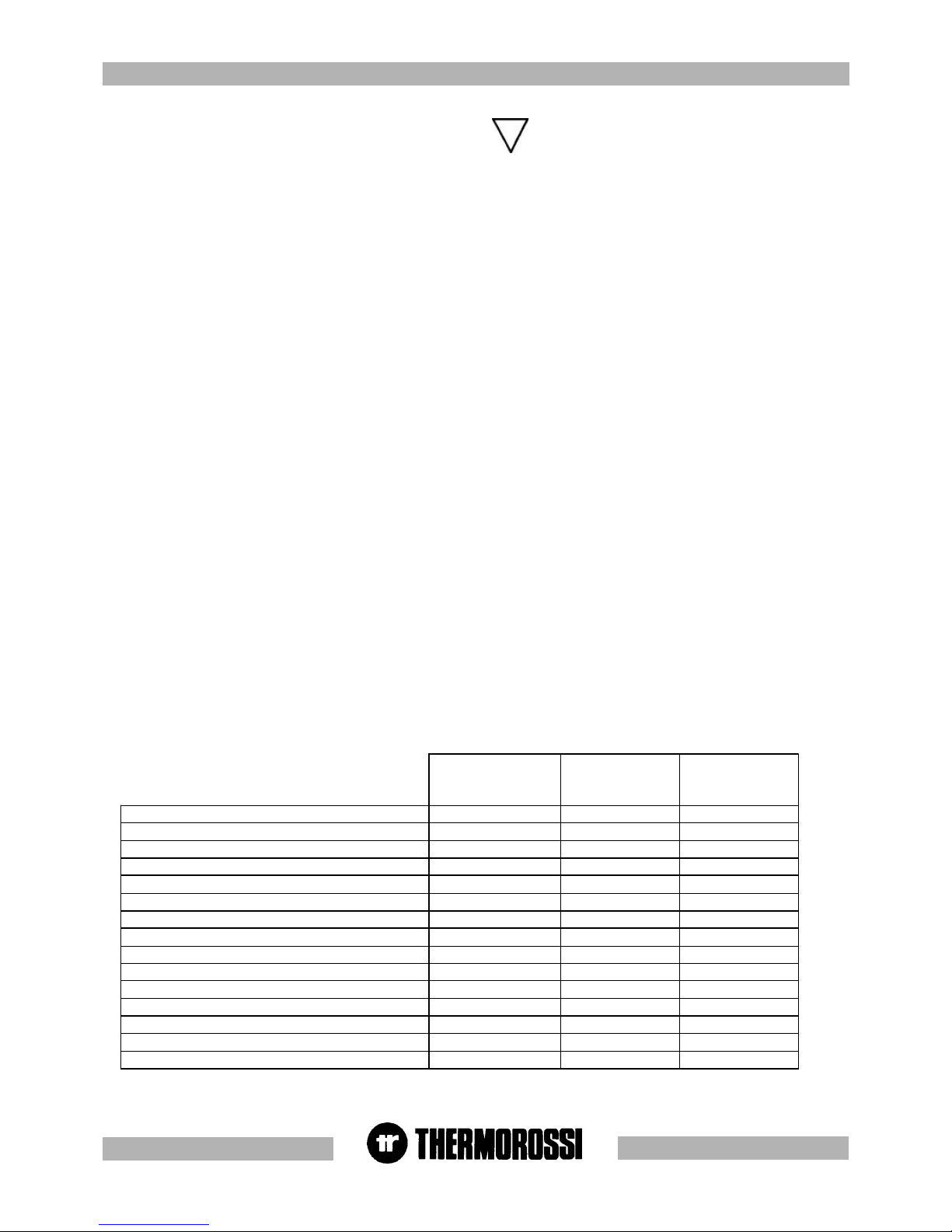
Ecotherm 5000
Easy
Ecotherm 5000
Metalcolor
Ecotherm 5000
Ceramic
element
Height (mm) 973 973 973
Depth (mm) 529 529 529
Length (mm) 460 460 460
Weight (Kg) 128 132 153
Rated power (Kw) 9,2 9,2 9,2
Reduced rated power (Kw) 2,5 2,5 2,5
Consumption min/max (Kg/h) 0,7 – 2,3 0,7 – 2,3 0,7 – 2,3
Smoke outlet tube D. (mm) 80 80 80
Min. draught at rated power (Pa) 12 12 12
Hopper capacity (Kg) ~ 14,5 ~ 14,5 ~ 14,5
Average smoke temp. at rated power (° C) 180 180 180
Smoke flow at rated power (g/sec) 5,5 5,5 5,5
Electricity 220 V 50 HZ 220 V 50 HZ 220 V 50 HZ
Max electrical consumption 1,17 A – 270 W 1,17 A – 270 W 1,17 A – 270 W
Min electrical consumption 0,34 A – 70 W ,34 A – 70 W ,34 A – 70 W
Page 5
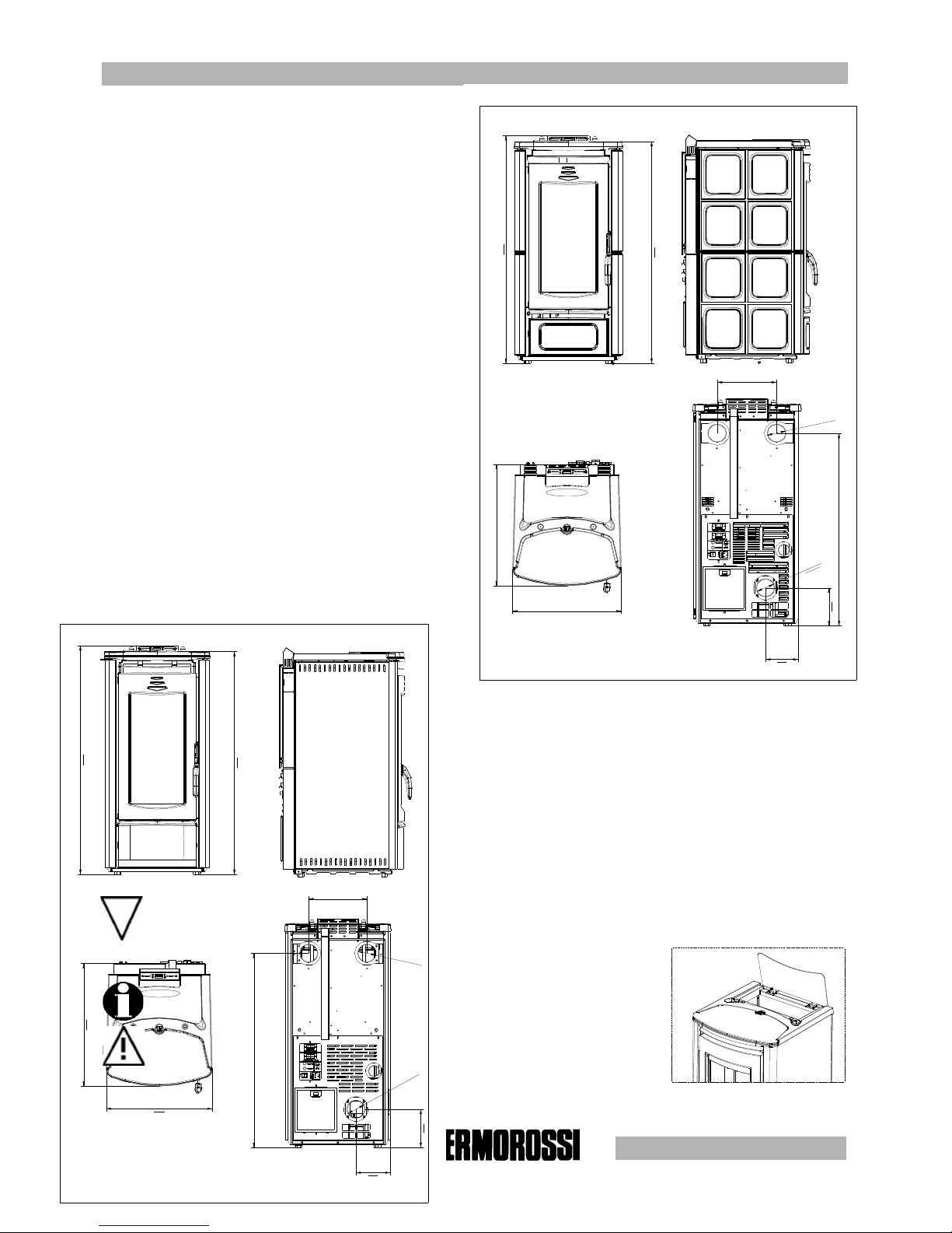
pg. 5
251
460
ECOTHERM 5000 EASY (in questo modello non è presente
la ceramica inferiore)
ECOTHERM 5000 METALCOLOR
529
165
152
838
O
8
0
O
8
0
973
955
460
ECOTHERM 5000 CERAMICA
529
152
O
8
0
165
838
O
8
0
973
955
251
33
33
3
GENERAL DESCRIPTIONGENERAL DESCRIPTION
GENERAL DESCRIPTIONGENERAL DESCRIPTION
GENERAL DESCRIPTION
3.13.1
3.13.1
3.1
OPERAOPERA
OPERAOPERA
OPERA
TING TING
TING TING
TING
TECHNOLTECHNOL
TECHNOLTECHNOL
TECHNOL
OGYOGY
OGYOGY
OGY
•Your heater has been built to fully satisfy all your heating and practical requirements. Top-grade components and functions managed with
microprocessor technology guarantee high reliability and optimal performance.
3.23.2
3.23.2
3.2
PELLETSPELLETS
PELLETSPELLETS
PELLETS
•The appliance is fuelled by pellets, that is, cylinders of compressed sawdust; this will make it possible for you to enjoy to the full the heat of the
flame without having to manually stoke the combustion.
The pellets are cylinders of compressed sawdust having a 6 mm diameter and a maximum length of 15 mm.
They have a maximum moisture content of 8%; a thermal value 4000/4500 Kcal/Kg and a density of approx. 620-630 Kg/m³.
The use of fuel which does not comply with the description given above immediately voids the heater warranty. Do
not use the appliance as an incinerator, at the risk of voiding the warranty.
3.33.3
3.33.3
3.3
THE FEEDBOTHE FEEDBO
THE FEEDBOTHE FEEDBO
THE FEEDBO
XX
XX
X
The feedbox is situated in the top part of the heater. The maximum load capacity of the tank is
approximately 14,5 Kg, but varies according to the specific weight of the pellets. The
manufacturer recommends emptying the hopper and vacuuming the screw feeder
zone once a month and during the summer period. Take special care when loading
the hopper as the screw feeder at its base is in motion.
Key
Ecotherm 5000 Easy The lower ceramic panel
is not included in this model
Ecotherm 5000 Ceramic
LEGENDA
Ecotherm 5000 Easy (In questo modello non è
presente la ceramica inferiore)
Ecotherm 5000 Ceramica
Page 6
pg. 6
44
44
4
INSTINST
INSTINST
INST
ALLAALLA
ALLAALLA
ALLA
TIONTION
TIONTION
TION
4.14.1
4.14.1
4.1
HEAHEA
HEAHEA
HEA
TER LTER L
TER LTER L
TER L
OCAOCA
OCAOCA
OCA
TIONTION
TIONTION
TION
CAUTION : Always use trolleys to move the appliance and the appliance must
always be in a vertical position. Follow the general guidelines set out in paragraph
1.1 to the letter. Keep in mind that the flooring of the room in which the heater is to
be installed must withstand the combined weight of the appliance and the pellets
contained in the tank.
CAUTION: The room in which the appliance will operate must be adequately ventilated
(minimum air intake 1300 m3/h). The appliance must be positioned at a minimum
safe distance from walls and furnishings. This distance will have to be increased
considerably if the objects surrounding the appliance are inflammable
(matchboarding, furniture, curtains, picture frames, sofas, etc...). The recommended
minimum distances are illustrated in the drawing below on the right. Installation in
the vicinity of heat-sensitive materials is only permitted if suitable insulating protection
is placed between the object and the appliance (ref. Uni 10683). Adjust the mounting
feet to obtain a slight gap between heater and flooring to ensure that the heater is
not resting directly on the floor. It is advisable to interpose a floor protector plate
between the heater and the floor if the latter is made of wood or other combustible
material.
4.1.14.1.1
4.1.14.1.1
4.1.1
INST INST
INST INST
INST
ALLAALLA
ALLAALLA
ALLA
TION OF METTION OF MET
TION OF METTION OF MET
TION OF MET
ALAL
ALAL
AL
COLCOL
COLCOL
COL
OR CASINGOR CASING
OR CASINGOR CASING
OR CASING
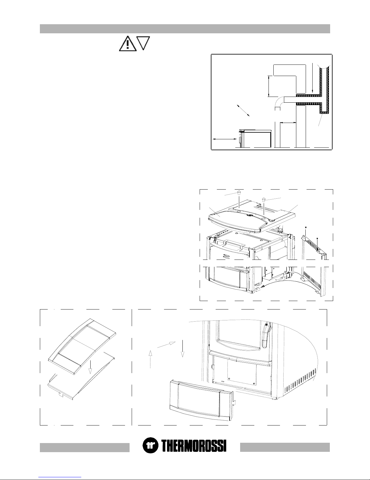
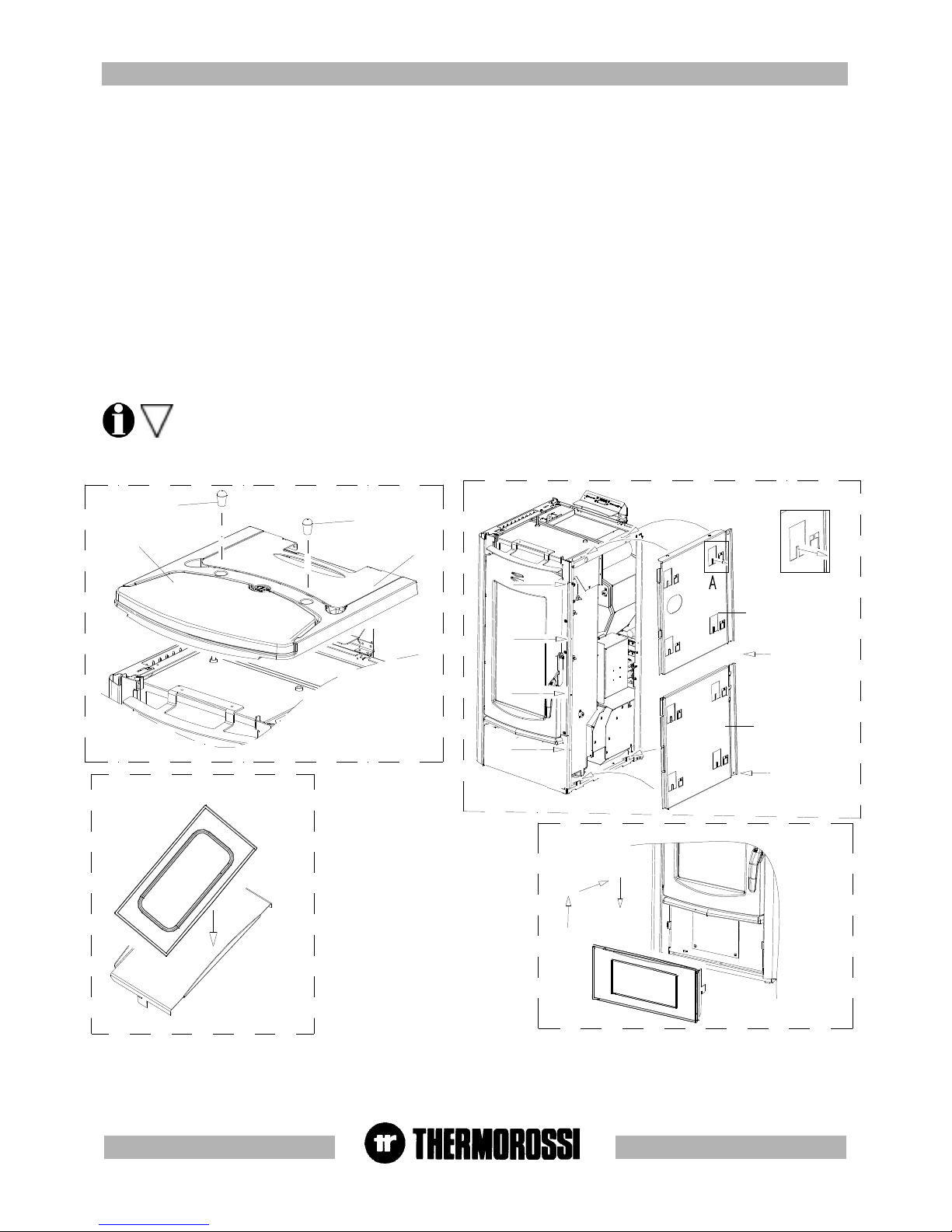
Once the heater has been positioned the next step is to install the side panels
and the top ceramic panel as shown in the image below on the left. Carry out
the following operations:
- Unscrew and remove the 2 knobs (H).
- Remove the cover (I).
- Now insert the side panel (M)'; position the bottom holes on the folds in the
base and fix the 2 top screws (Figure 1).
- Next remount the complete cover (I) and the top ceramic panel (L) and
screw back on the 2 knobs (H) removed earlier.
- Fix the lower front ceramic panel to its support with the silicone provided;
degrease and clean the ceramic panel support before gluing the parts to
ensure optimal adhesion. Leave the ceramic panel in the position illustrated in
Figure 2 and wait 24 hours before handling it.
- Next fasten the lower ceramic panel to the heater following the instructions
in Figure 3 .
Remember that the heater must be completely cooled down before the side
panel can be cleaned with a soft cloth and water.
The casing on the easy model is factory-mounted before delivery .
450 mm SE MATERIALE COMBUSTIBILE
450 mm SE MATERIALE COMBUSTIBILE
ISOLANTE TERMICO
2
0
0
m
m
S
E
M
A
T
E
R
I
A
L
E
C
O
M
B
U
S
T
I
B
I
L
E
200 mm SE MATERIALE
COMBUSTIBILE
Tee ispezionabile
H
H
I
L
M
Figura 1
Figura 2
Figura 3
Key
200 / 450 mm if combustible material
Heat insulating material
Inspectable Tee element
Figure
LEGENDA
200 / 450 mm se materiale combustibile
Isolante termico
Tee ispezionabile
Figura
Page 7
pg. 7
4.1.24.1.2
4.1.24.1.2
4.1.2
MOUNTING CERAMIC CASING MOUNTING CERAMIC CASING
MOUNTING CERAMIC CASING MOUNTING CERAMIC CASING
MOUNTING CERAMIC CASING
The next step, after positioning the heater, is to mount the ceramic casing as illustrated in the figures below.
Carry out the following operations:
- Unscrew the 2 knobs and remove the top cast iron cover.
- Mount the right ceramic panel supports (figure 2) following the procedure set out below:
Undo screws A and B and remove them momentarily. Fix support SID by firstly inserting the bottom folds on the seat of the heater base, next
re-insert and fasten screws A and B. Undo screws C and B and remove them momentarily. Fix support SSD then re-insert and fasten screws
C and D. Next screw in screws E and F provided. Screw in screws G and H provided.
Bend the tabs slightly (indicated in detail A of Figure 2) outwards from the heater. Next fix the side ceramics to the supports by securing them
to the bent tabs.
Next mount the left ceramic panel supports using the same procedure as described above for the right ceramic panel supports (Figure 2).
Next attach the side ceramic panels to the supports.
- Fix the lower front ceramic panel to its support (Figure 3) with the silicone provided; degrease and clean the ceramic panel support before gluing
the parts to ensure optimal adhesion. Leave the ceramic panel in the position illustrated in Figure 3 and wait 24 hours before handling it.
- Next fasten the lower ceramic panel to the heater following the instructions set out in Figure 4.
- Lastly position the top ceramic panel (Figure 1) and screw in the 2 knobs removed earlier.
Special care must be taken when handling and mounting the ceramics in order to prevent breakages that are not covered by
warranty. Small imperfections on the surfaces of the ceramics such as: dimples, shivering and slight colour variations are
normal characteristics of handcrafted ceramics which make each piece unique.
H
H
I
L
DETTAGLIO A
Figura 2
A
B
C
D
F
E
G
H
SID
SSD
Figura
1
3
Figura
4
Figura
Key
Detail A
Figure
LEGENDA
Dettaglio A
Figura
Page 8

pg. 8
55
55
5 DESCRIPTIONS OF CONTROLS
5.15.1
5.15.1
5.1
DESCRIPTION OF CONTRDESCRIPTION OF CONTR
DESCRIPTION OF CONTRDESCRIPTION OF CONTR
DESCRIPTION OF CONTR
OL POL P
OL POL P
OL P
ANEL ANEL
ANEL ANEL
ANEL
AND HEAAND HEA
AND HEAAND HEA
AND HEA
TER REAR PTER REAR P
TER REAR PTER REAR P
TER REAR P
ANELANEL
ANELANEL
ANEL
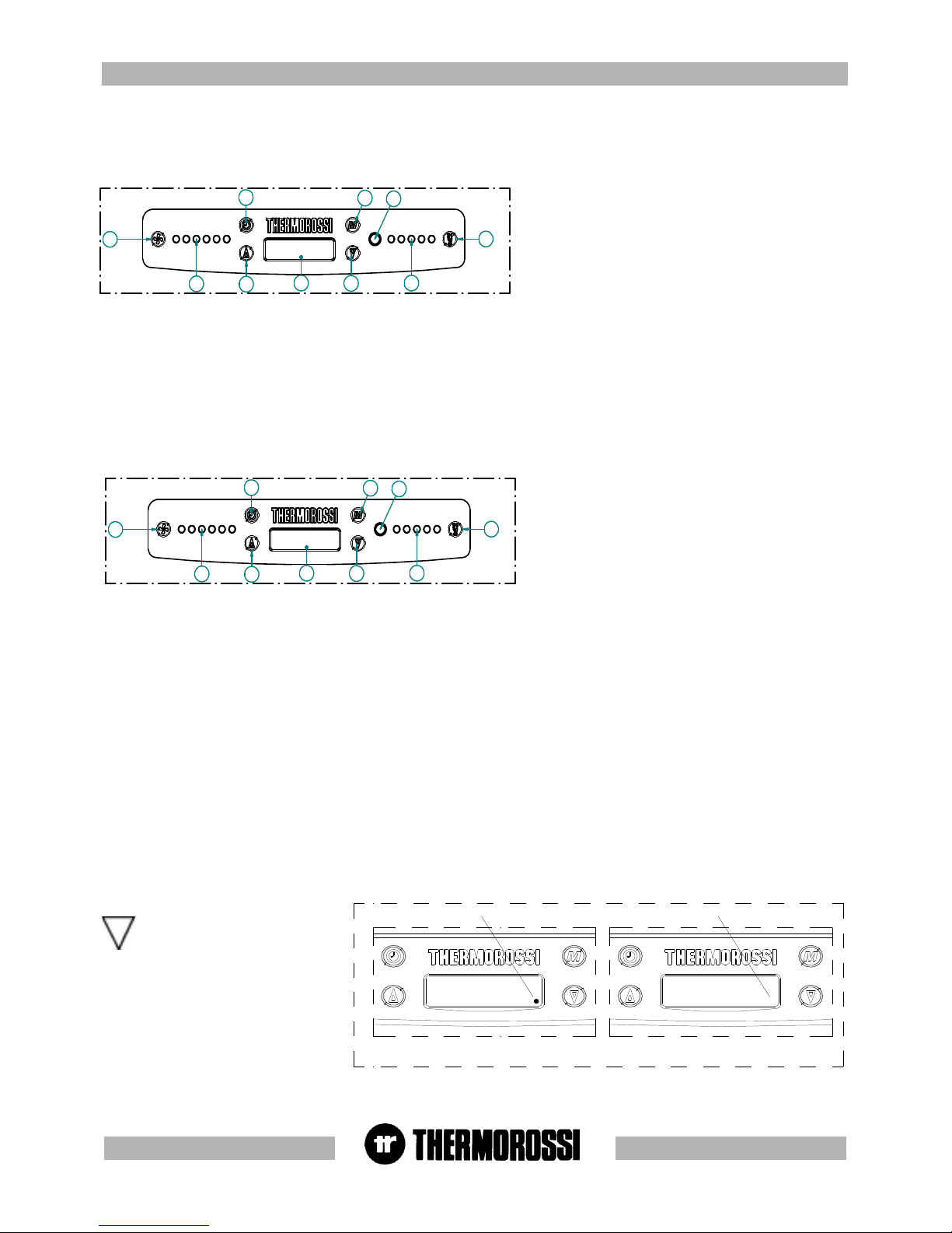
5.1.1 DESCRIPTION OF THE CONTROL PANEL
There are two main control pushbuttons marked with the ventilation symbol (2) and the symbol of the flame (1).The flame pushbutton (1) sets
the power of the heater with 5 levels available which are activated as the 5 leds light up in sequence (10). The off cycle is activated when
all power leds are turned off. Key (2) controls the ventilation of the heater. It is activated when the heater body reaches a temperature over
42 °C. The fan can be set to any of speed levels (9): when the heater is on the ventilation cannot be switched off .
5.1.2 BACK PANEL OF THE HEATER
A description of the functions of the buttons and LEDs on the back panel of the
heater:
(11) Main switch 0-1
(12) Heater electrical power outlet 220-240V 50 Hz.
(13) Overtemperature thermostat button cap.
In the event of overtemperature this safety thermostat stops the loading of
pellets. When it is activated LED 15 comes on. To restart the heater you
need to wait until it cools down, then verify the cause for the overheating,
remove the cause, unscrew the protective cap and press the button (13) .
(14) Feed motor test indicator light. When the pellet screw feeder is set in
motion the light must come on.
(15) Reset thermostat tripped indicator light. This LED comes on when
the reset thermostat is activated.
(16) Power outlet for additional chronothermostat connection.
(additional chronothermostat not supplied )
(17) Power outlet for additional room temperature thermostat
connection. (additional room temperature thermostat not supplied)
All controls and indicators are presented here below :
(1) Insert on/off and flame adjustment button . When you press this button the appliance (10) switches to Start / ON / OFF.
Up to 5 leds (10) are activated when pressed repeatedly.
(2) Ventilation setting button . Press this button to set the desired level of ventilation: up to a maximum of 6 speeds are available,
indicated by the lighting of the corresponding leds (9).
(3) (4) Auxiliary setting keys.
Keys (3) and (4) are operating keys necessary when on-off cycles are programmed, for operative levels, clock setting, etc..
5) Programming Enable / Disable keys.
(6) “MENU” selection button To access the main menu press the button marked with 6. Press button 6 repeatedly to scroll the
adjustment, setting and programming windows.
(7) Display
(8) Infrared sensor for remote control
(9) Ventilation level leds .
(10) Combustion level leds
1
2
3
4
5
6
7
8
9
10
11
13
14
15
16
17
12
Key
Room temperature thermostat
Chronothermostat - modem
Motor. LED
Reset LED
Reset
LEGENDA
Termostato ambiente
Cronotermostato - modem
Spia motor.
Spia riarmo
Riarmo
Page 9
pg. 9
5.2 D5.2 D
5.2 D5.2 D
5.2 D
AA
AA
A
Y Y
Y Y
Y
AND AND
AND AND
AND
TIME SETTINGTIME SETTING
TIME SETTINGTIME SETTING
TIME SETTING
The heater must be fed with the rear switch in position "1". Display (7) may show the inscriptions On , OFF or Start.
To set the time and the day of the week carry out the
procedures described below. Press once the key (6), and the
inscription HoUr will flash. After a few seconds the fixed
inscription days will appear. In order to ad just the day,
repeatedly press key (4) and/or (3) until the led turns on in
area (9) which corresponds to the present day; Monday is
indicated by the 1st led on, Tuesday is indicated by the 2nd led
on,....... Saturday is indicated by led (6) on, while Sunday
corresponds to all 8 leds being on. Then confirm the day by
pressing the key (1). The 2 digits representing the hours will start flashing in the display: it is possible to select the present hour using the
arrow keys (4) and/or (3); the selection must be confirmed by pressing key (1). The 2 digits indicating the minutes will start flashing: it is
possible to select the present minutes using the arrow keys (4) and/or (3), the selection must be confirmed by pressing the key (1). The
setting of the day and of the hour is now completed. For the entire procedure to be confirmed and to move back to the heater status display,
key (6) must be repeatedly pressed until the operating status is displayed: On , Off, or Start. :
5.3 ON/OFF PROGRAMMING.5.3 ON/OFF PROGRAMMING.
5.3 ON/OFF PROGRAMMING.5.3 ON/OFF PROGRAMMING.
5.3 ON/OFF PROGRAMMING.
The heater must be fed with the rear switch in position "1". Display (7) may show the inscriptions On , OFF or Start.
It is possible to carry out the weekly programming by setting up to 3 on/off cycles for each day from Monday to Sunday. To carry out the
programming, push button (6) must be pressed twice until
the inscription cr on is on.: in area (9) a led goes on (which
indicates that the first day of the week, Monday, is being
programmed). Inscription On1 will appear on the display,
and the 2 digits representing the hours will turn on. Press
button (3) and/or (4) to enter the hour of the first cycle start
time. To confirm the selection press the button (1). The two
digits representing the minutes will be turn on. Press button
(3) and/or (4) to enter the minutes of the first cycle start
time. For the selection to be confirmed press the key (1). The
first hour for the Monday on-cycle has been set. Then the inscription OFF1 will appear in the display and the two digits representing the
hours will turn on. When the (3) and/or (4) is pressed the hour of the first off-cycle is entered. To confirm the selection press the button (1).
The two digits representing the minutes will be turn on. By pressing the key (3) and/or (4) the minutes for the first off-cycle will be entered
To confirm the selection press the button (1). At this point the first on-off cycle for Monday has been entered. Later, it is possible to set the
Monday’s second on-off cycle (shown with the display of On2 and OFF2) and the third Monday’s on-off cycle (shown with the display On3
and OFF3) . Inside the programming menu, if for example the Wednesday’s programming is to be changed, go to the third green led by
pressing key(2): then it is possible to change the on-off programs for Wednesday, confirm the change by pressing the key (6). If the second
on-off cycle is not required simply set the ON2 time as 00:00 and the OFF2 time as 00:00 .
The programming procedure ends when you confirm the last data entered by pressing button (6) or when you exiting the programming menu.
Pressing pushbutton (5) programming is enabled/disabled (Enabled= message on cr temporarily displayed and, at the same time, a fixed
point is present on the right side at the bottom of the display. Disabled= message of cr temporarily displayed and, at the same time, the point
on the right side at the bottom of the display is not present.) : this function is useful if one wants to prevent the weekly established
programming. With the programming active, the operating conditions at the start-up (combustion power – ventilation speed) are the same as
set-up before the last off-cycle of the heater: this is the case if the off-cycle has been done through the programming and not through a
manual action. In case the off-cycle (if carried out while the heater cycle is being controlled by the programming) is activated manually, at the
next start up controlled by the programming the heater will be set at the 1st combustion power level and the 1st ventilation speed.
In order to display the present time and programmings, key (6) must be repeatedly pressed until the current time is
displayed. By pressing keys (3) and/or (4) all programming values will be displayed : to exit this condition, twice press the
key (6) .
1
2
3
4
5
6
7
8
9
10
1
2
3
4
5
6
7
8
9
10
Esempio di come si presenta il display
con la programmazione attivata.
Esempio di come si presenta il display
con la programmazione disattivata.
On
Presenza fissa punto
On
Assenza punto
Key
Point steady presence
Point absence
Example of how the display
appears with the programming
activated/deactivated.
LEGENDA
Presenza fissa punto
Assenza punto
Esempio di come si presenta il
display con la programmazione
attivata / disattivata
In the event of a programmed cycle
on always ensure that the brazier is
clean and seated correctly in its
lodging: failure to keep the brazier
clean can reduce the life of the
spark plug.
Page 10

pg. 10
5.4 OPERA5.4 OPERA
5.4 OPERA5.4 OPERA
5.4 OPERA
TING LEVEL SETTINGTING LEVEL SETTING
TING LEVEL SETTINGTING LEVEL SETTING
TING LEVEL SETTING
The heater must be fed with the rear switch in position "1". Display (7) may show the inscriptions On , OFF or Start. ".
Your appliance is delivered with an excellent program installed that favours combustion yield; the program is called P 1.
If you are using pellets with an out-of-standard incidence of residues after combustion in the brazier, alternative levels may be selected:
P 2 : this program increases the smoke suction unit speed acceleration.
(program P2 increases air delivery to the burner which promotes the combustion of tightly compacted pellets: this program reduces
combustion efficiency).
P 0 : when using too long pellets and/or flue outlets with very high vacuum, over 2 mm water column.
The pellet consumption value is not affected by the operating level settings.
Select the required level by acting as follows:
Repeatedly press three times the key (6) until the inscription LIV flashes on the display and, then, the corresponding level set on the heater
will show ( P1 o P2 o P0) In order to change the operating level as key (4) is kept pressed, press the key (3).
By holding down button (4) and pressing button (3) repeatedly the level changes in the following sequence: P2... ...P0 ... P1.
If the change is made while the insert is running the difference in the flame will be apparent. It is mandatory to pay
particular care when selecting the most appropriate operating cycle for your installation. After the selection of the
operating cycle a thorough cleaning of the brazier is mandatory.
For an overall confirmation and to return to the status display of the heater, repeatedly press the key (6) until the operating status is
displayed.
When the programming is enabled (temporary inscription on cr on the display and, at the same time, a fixed point is present on the
right side at the bottom of the display) any additional chronothermostat (see para. 7.2) is deactivated.
1
2
3
4
5
6
7
8
9
10
66
66
6
USE OF USE OF
USE OF USE OF
USE OF
THE HEATHE HEA
THE HEATHE HEA
THE HEA
TERTER
TERTER
TER
6.16.1
6.16.1
6.1
5.15.1
5.15.1
5.1
SWITSWIT
SWITSWIT
SWIT
CHING ON CHING ON
CHING ON CHING ON
CHING ON
THE HEATHE HEA
THE HEATHE HEA
THE HEA
TERTER
TERTER
TER
Before using the appliance check that all the movable parts are in place; also remove any labels and stickers from the glass to avoid having
permanent traces remain on the surfaces.
Turn the switch installed on the back of the heater to position "1" (= ON). Press button (1) to start the start up phase. When key (1) is
repeatedly pressed, the desired combustion level can be set and it will be active at the end of the ignition stage.
The electrical heater will start to overheat and after a few minutes the first lot of pellets will start dropping into the brazier. This occurs
because the screw feeder has to fill up because it is completely empty. The first time the heater is started up the start up phase will have to
be carried out twice for this very reason.
CAUTION : The start up phase (word Start appearing on the display) takes 20 minutes during which the heater ignores any
commands transmitted to it. After this time has elapsed the word ON appears on the display. The fan starts as soon as the heater
body exceeds 42°C. During the work stage it is then possible to adjust combustion and the ventilation:
Combustion is adjusted by 5 leds (through key (1)) , while the ventilation adjustment is distributed over 6 levels shown by the leds
that turn on in succession (through key (2)).
To turn the heater on it is necessary for the inscription OFF to be present on the display; if it is not present, the key (6) must be
repeatedly pressed until the inscription OFF appears.
The heating capacity is adjusted by pressing key (1) or on the remote control provided . Act on this command to adjust the quantity of pellets
fed to the firebox. Maximum combustion power is achieved when all 5 leds are lit.
Caution: The fan starts as soon as the heater body exceeds 42°C. The fan setting is expressed visually by means of 6 different
positions represented by 6 bars: press button (2) repeatedly to regulate it.
A slight vibration of the heater is quite normal when it is running.
6.2 HEA6.2 HEA
6.2 HEA6.2 HEA
6.2 HEA
TER COMBTER COMB
TER COMBTER COMB
TER COMB
USTION USTION
USTION USTION
USTION
AND AND
AND AND
AND
VENTILAVENTILA
VENTILAVENTILA
VENTILA
TION TION
TION TION
TION
ADJUSTMENTSADJUSTMENTS
ADJUSTMENTSADJUSTMENTS
ADJUSTMENTS
Page 11

pg. 11
A practical infrared remote control is supplied with the heater: press the left button to adjust the ventilation level, press the right button to
adjust the combustion level. If the heater is supplied with a white radio control (optional) the infrared control only works when the MANUAL
setting is set on the white handheld radio control.
6.3 INFRARED REMO6.3 INFRARED REMO
6.3 INFRARED REMO6.3 INFRARED REMO
6.3 INFRARED REMO
TE CONTRTE CONTR
TE CONTRTE CONTR
TE CONTR
OLOL
OLOL
OL
INTRODUCTION
The handheld radio control is the device that allows you to control Ecotherm in order to optimise consumption and its functions. Keep in mind
that radio wave transmissions can be affected by the surrounding environment: the presence of thick walls can reduce the transmission that
normally extends to 6-7 metres.
6.46.4
6.46.4
6.4
OPERAOPERA
OPERAOPERA
OPERA
TION OF TION OF
TION OF TION OF
TION OF
THE THE
THE THE
THE
WHITE HANDHELD RADIO CONTRWHITE HANDHELD RADIO CONTR
WHITE HANDHELD RADIO CONTRWHITE HANDHELD RADIO CONTR
WHITE HANDHELD RADIO CONTR
OL (OPTIONOL (OPTION
OL (OPTIONOL (OPTION
OL (OPTION
AL)AL)
AL)AL)
AL)
3
4
2
1
7
6
5
8
9
10
11
13
12
6.4.16.4.1
6.4.16.4.1
6.4.1
Indicators of the handheld radio controlIndicators of the handheld radio control
Indicators of the handheld radio controlIndicators of the handheld radio control
Indicators of the handheld radio control
(1) Flame adjustment button
(2) Ventilation adjustment button
(3) (4) Auxiliary keys.
(5) “Room temperature detected by the radio control's sensor” indicator .
(6) "Ventilation" indicator.
(7) " Combustion" indicator.
(8) “ Room temperature setting" indicator : this is the room temperature that you
wish to reach by means of buttons 3 and 4.
(9) Area of the display where the operating program is displayed.
(10) Battery charge level
(11) Switch 0-1 radio control power
(12) Battery charger connection.
(13) Code selector and Batteries compartment cover
The Thermocomfort radio control can be used with 4 different operating programs:
- Manual (MANUAL appears in area (9) of the display).
- Automatic 5 (AUTO 5 appears in area (9) of the display).
- Automatic 3 (AUTO 3 appears in area (9) of the display) .
- Economy (ECONOMY appears in area (9) of the display).
To change the operating program turn the switch (11) to "1". Press and hold down button (3) until the set program begins to blink on the
display (9). Now release button (3) and press button (3) and/or (4) repeatedly until you select the desired operating program.
Caution: to guarantee optimal data transmission it is advisable to always place the radio control in its support in a vertical
position.
The following operations must be carried out the first time the heater is started up :
- Turn the switch (11) to ON (see drawing below)
- Connect the radio control by means of the battery charger supplied to the power line, ( it must be recharged for
at least 5 days); as the rechargeable batteries could be partially or completely flat). Leave the radio control
connected at all times, by means of the battery charger, to the power supply line.
The heater must be energised and the switch turned to position "1".
At the end of the winter season it is mandatory to switch off the radio control completely, by means of the switch
situated inside the battery compartment, in order to preserve the life of the batteries. The batteries are
guaranteed for 6 months. When the batteries are exhausted dispose of them safely. It is normal for the tempera-
ture sensor to detect temperatures which are slightly different to the real ones: variations caused by the
environment in which the radio control is positioned.
MANUAL program
In the MANUAL program the room temperature thermostat is disabled. Press button (1) and the flame symbol begins to blink. Press button (3)
to decrease the combustion level by lighting up the bars sequentially, vice versa press button (4) to increase the combustion level. The
combustion level changes with each press of buttons (3) and (4).
Press button (2) and the ventilation symbol blinks. Press button (3) and the combustion level decreases,
vice versa press button (4) to increase the combustion level. The ventilation level changes with each press of buttons (3) and (4) . Caution:
it is possible that, due to radio interference or sending commands too close together, the changes will not be implemented. With this program
you can also use the infrared control supplied. It is normal that in the manual cycle the ventilation is often set at the maximum speed in order
to cool the heater body more effectively.
Page 12

pg. 12
ECONOMY program
In the ECONOMY program the heater always operates at the minimum combustion level and the minimum ventilation level. You cannot use the
infrared control with this program .
CAUTION: THE HEATER MUST ALWAYS BE SWITCHED ON AND OFF FROM THE CONTROL PANEL LOCATED ON THE HEATER.
FOR THE RADIO CONTROL TO WORK THERE MUST NOT BE AN ACTIVE PROGRAM SET ON THE CONTROL PANEL LOCATED
ON THE HEATER OR AN EXTERNAL ROOM TEMPERATURE THERMOSTAT OR AN EXTERNAL CHRONOTHERMOSTAT.
6.4.2 TRANSMISSION CODES SETTINGS.6.4.2 TRANSMISSION CODES SETTINGS.
6.4.2 TRANSMISSION CODES SETTINGS.6.4.2 TRANSMISSION CODES SETTINGS.
6.4.2 TRANSMISSION CODES SETTINGS.
Before beginning any maintenance operation ensure that the appliance is in the OFF phase and disconnect it from the electric power outlet.
If several heaters are installed in close locations it may be necessary to set different transmission codes. The change of code must be made
both on the motherboard inserted in the heater (see figure below left ), and in the radio control (see figure below left). Position the switch 0-1
(located on the back of the heater) on 0. To access the board you need to remove the heater's right side panel as described in the dedicated
paragraph and remove the board cover by undoing the two screws as indicated in the figure below on the right.
The codes must be identical, and for this purpose you could use the numbers marked on the microswitches as reference. Firstly set the new
code on the motherboard, next set the new code on the remote control and then switch the remote control on and off with the switch (11)
located on the back of the remote control.
AUTO 5 program
In program AUTO 5 the room temperature thermostat is enabled. The radio control adjusts the ventilation and the combustion automatically in
relation to the target room temperature set in display area (8). The desired room temperature appears in area (8). You can vary the desired
room temperature by simply pressing button (3) and/or (4) (variation indicated in area (8)). The remote control will set the maximum
combustion and ventilation levels and modulate them both as the room temperature (5) approaches the target temperature (8). When the
target temperature (8) in the room (5) is reached, the combustion level will stabilise on a bar as will the ventilation level. Caution: it is possible
that, due to radio interference, the commands sent to the heater will not be implemented. You cannot use the infrared control with this
program. Caution: the power and the ventilation depend on the preset value, if the required temperature is too high or not reachable the
heater could operate at maximum power for long periods of time.
PALMARE GESTITO VIA ONDE RADIO
SELETTORE CODICI PER RADIOCOMANDO
3
2
1
O
N
4
4
1
O
N
3
2
2
1
3
4
5
6
PER RADIOCOMANDO
SELETTORE CODICI
4
3
ON
2
1
4
3
ON
2
1
AUTO 3 program
In program AUTO 3 the room temperature thermostat is enabled . The remote control adjusts the ventilation and combustion automatically in
relation to the target room temperature set in display area (8). The desired room temperature is displayed in area (8). You can vary the
desired room temperature by simply pressing button (3) and/or (4) (variation indicated in area (8)). The remote control will set the
combustion power at level 3 and the ventilation at level 4 and modulate them both as the room temperature (5) approaches the target temperature (8). When the target temperature (8) in the room (5) the combustion level will stabilise on a bar as will the ventilation level. Caution: it is
possible that, due to radio interference, the commands sent to the heater are not acknowledged???implemented. You cannot use the infrared
control with this program . Caution: the power and the ventilation depend on the preset value, if the required temperature is too high or not
reachable the heater could operate at maximum power for long periods of time.
Caution: ensure correct and equivalent position of
the microswitches.
KEY
code selector for handheld radio control
radio wave-controlled code selector for
handheld radio control
LEGENDA
selettore codici per radiocomando
selettore codici per radiocomando
palmare gestito via onde radio
Page 13

pg. 13
6.4 CHANNELLING6.4 CHANNELLING
6.4 CHANNELLING6.4 CHANNELLING
6.4 CHANNELLING
To obtain an optimal flow of channelled hot air:
- Avoid narrow or reduced sections, sharp curves, downhill runs in the tubing.
- Reduce the horizontal runs as much as possible.
- Use pipes with smooth inner surfaces made of material capable of resisting
continuous temperatures of 150°C.
- Insulate pipes with mineral wool (resistant to at least 150°C).
If you follow the instructions given above it is possible to channel:
- up to 16 metres using 1 vent
- up to 16 metres using 2 vents
- up to 16 metres using 3 vents
- up to 16 metres using 4 vents
The heater is supplied with both fittings already mounted.
If you wish to channel the air with 1 vent only then you must (see figure 4) partially
undo the screw C1 using a suitable screwdriver, remove screws C2 and C3,
remove the pipe E and replace it with the cover D which you must fasten to the
heater (see figure 4). To start the air channelling act on lever A (figures 1 2 and 3).
To act on lever A firstly open the hopper compartment and, using the hook provided,
lift the lever and position it where necessary.
The A control is extremely hot. In order to prevent burns, it is
mandatory to use the tool provided to act on the control.
C2
Figura 4
D
E
C2
C1
(Posizioni intermedie)
Figura 2
Figura 1
(Tutta l'aria canalizzata)
A
Figura 3
(Nessuna canalizzazione)
A
A
6.4 FIL6.4 FIL
6.4 FIL6.4 FIL
6.4 FIL
TERTER
TERTER
TER
This practical device prevents the circulation of dust which is always present in
household environments. The filter is installed at the back of the heater (see figure on
the right). Clean frequently to ensure the maximum availability of hot air when the
heater is operating (wash the filter with cold water then dry thoroughly every 5
days).
6.4.3 CARE AND MAINTENANCE RADIO CONTROL6.4.3 CARE AND MAINTENANCE RADIO CONTROL
6.4.3 CARE AND MAINTENANCE RADIO CONTROL6.4.3 CARE AND MAINTENANCE RADIO CONTROL
6.4.3 CARE AND MAINTENANCE RADIO CONTROL
The radio control has been designed and produced to the strictest standards and must be handled with great care.
If you observe the guidelines set out below, the radio control will provide a long trouble-free performance:
-Protect the radio control against humidity! Precipitation, humidity and liquids corrode the electronic circuits. If the radio control is wet,
disconnect it immediately from a power source, remove the battery, open it and allow it to dry at room temperature.
-Do not use or store the radio control in dusty or dirty environments. The dust/dirt could damage the movable parts of the radio control.
-Do not store the radio control in very hot environments. High temperatures could shorten the life of the electronic devices, damage the
batteries and deform or even melt plastic parts. -Do not store the radio control in cold environments. When it heats up (when it returns to
normal operating temperature), humidity could form inside it and damage the electronic circuits.
-Do not drop the radio control, do not hit or bump it and do not shake it. Actions such as these could damage the internal circuits of the device.
-Do not use corrosive chemical substances, caustic solutions or detergents to clean the radio control.
All the above guidelines apply equally to the radio control, the battery, the battery charger, and all the accessories.
The parts subject to wear (such as batteries, keypads, lodging compartments, small compartment parts) are guaranteed for 6 months from the
purchase date. The guarantee does not apply if the defect is caused by non-conforming use and/or if the instructions and guidelines described
above are not observed to the letter. Non-conformities must be reported within two months of having identified them. Devices or parts returned
for replacement become the property of Thermorossi. The presence of irregular black-blue lines on the display (also present when deenergised and battery flat or missing) indicate that the glass screen of the display is damaged following a fall or impact: in this case the
breakage is not covered by the guarantee.
Key
Figure 1 (all the hot air is channelled )
Figure 2 (Intermediate positions)
Figure 3 (no channelling)
FIGURE 4
LEGENDA
Figura 1 (tutta l'aria canalizzata)
Figura 2 (Posizioni intermedie)
Figura 3 (nessuna canalizzazione)
Figura 4
Page 14

pg. 14
88
88
8
CLEANING AND MAINTENANCECLEANING AND MAINTENANCE
CLEANING AND MAINTENANCECLEANING AND MAINTENANCE
CLEANING AND MAINTENANCE
8.18.1
8.18.1
8.1
FOREWORDFOREWORD
FOREWORDFOREWORD
FOREWORD
Before commencing any operation disconnect the appliance from the electric power outlet. Your ECOTHERM pellet heater does not
require any special maintenance; simply adhere to the simple and basic but regular controls and general cleaning. This will guarantee
regular operation and optimal output at all times. If the product is unused for a prolonged period of time it is mandatory to inspect the
smoke channel and outlet to ensure that there are no obstructions before use. It is necessary to accurately follow the directions given
below: Otherwise severe damages may occur for the product, the installation, objects and the people who use the generator.
CAUTION: The manufacturer denies all responsibility for the life of the electrical heater if subjected to excessive start ups. The
manufacturer recommends setting a suitable room temperature value in the chronothermostat in order to prevent this possibility.
CAUTION: Use N.O. (normally open) contacts for the connection to the chronothermostat. Contact 1-3 of the chronothermostat
mod. "Perry".
CAUTION: In the event of connections to the chronothermostat Thermorossi shall not be held responsible for the insert not starting
up, smoke leaks, breakage of the lighting component. In the event of a programmed cycle on always ensure that the brazier is
clean and seated correctly in its lodging.
7 ADDITIONAL ROOM TEMPERATURE THERMOSTAT (not supplied)
ADDITIONAL CHRONOTHERMOSTAT (not supplied)
The control panel ensures that your heater is provided with all the required programming and temperature adjustment functions:
Two gland nuts are fitted to the back of the heater near the power point.
They refer to two operating modes:
à With the room temperature thermostat. à With the chronothermostat or modem.
Simply connect the additional room temperature thermostat to the gland nut on the heater marked
"Room Temperature Thermostat" or the additional chronothermostat to the gland nut on the heater marked "Chronothermostat - modem".
Use only contacts 1 and 2.
Contacts 1-2 are defined as "CLEAN" contacts and they must never be fed with 220 V. If the board is energised with 220V or
voltages exceeding 6 V the control board will be permanently damaged and will not be covered by the GUARANTEE.
7.1 OPERATING WITH THE ADDITIONAL ROOM TEMPERATURE THERMOSTAT (NOT SUPPLIED )
An additional room temperature thermostat can be installed by connecting it to the cable gland marked “THERMOSTAT” at the back of the
heater. The operating principle is as follows:
-When the room temperature reaches the set temperature (only during the RUNNING phase) the thermostat closes the contact and the heater
shifts to the minimum room fan speed and minimum combustion power. By using the room temperature thermostat the heater does not shut
down, therefore electrical energy consumption is kept to the minimum and the heater has a longer life.
-When the room temperature drops the thermostat opens the contact and the heater returns to its original position in terms of thermal power
and ventilation.
-In this position it is not possible to start up the heater automatically or shut it down automatically.
CAUTION: N.C. (normally closed) contacts must be used for the connection to the additional room temperature thermostat.
Contacts 1-2 of the chronothermostat mod. "Perry".
7.2 OPERATING WITH THE ADDITIONAL CHRONOTHERMOSTAT (NOT SUPPLIED )
As an alternative to the room temperature thermostat, a chonothermostat can be installed by connecting it to the cable gland marked
“CHRONOTHERMOSTAT” fitted to the back of the heater. Using this outlet when the chronothermostat contact closes the START cycle starts,
whereas when the contact opens the OFF cycle starts. The operating level at start up (combustion power - fan speed ) is the same as the
level used before the last time the heater shut down. This operation can also occur by adjusting its room temperature. Once the desired temperature set on the chronothermostat is reached the contact opens and executes the shut down cycle. Similarly when the room temperature
drops below the set temperature the contact closes and the START cycle starts. If an unsuitable room temperature value is selected the
heater will be subjected to continual ON-OFF cycles, consequently the increased number of start ups will result in greater consumption of
electrical energy. The chronothermostat can be used to program temperatures, times and dates for the ON-OFF cycles. It is therefore
possible to program a momentary shutting down of the heater according to the room temperature.
Page 15

pg. 15
8.28.2
8.28.2
8.2
CLEANING CLEANING
CLEANING CLEANING
CLEANING
AND MAINTAND MAINT
AND MAINTAND MAINT
AND MAINT
AINING AINING
AINING AINING
AINING
THE HEATHE HEA
THE HEATHE HEA
THE HEA
TERTER
TERTER
TER
• EVERY DAY remove all combustion residues from the brazier then remount the brazier and the catalyst (Figure 1 shows a clean brazier).
Caution: make sure, before every start up, that the brazier is clean and if necessary also thoroughly clean the burner with a suction unit.
Take particular care to clean the area near the spark plug : this will guarantee the correct operation of the appliance .
• EVERY 3 DAYS lift and drop the tube scraper rods several times (Figure 2)
• EVERY 5 DAYS clean the room air filter located at the back of the heater (Figure 11).
• EVERY WEEK empty the ash pan "V" of all residual ash (figure 9).
• EVERY WEEK vacuum the residual ash from the compartment "V1" under the brazier.To facilitate vacuuming remove the blade and brazier
(Figure 10).
• EVERY 2 WEEKS clean the smoke exhaust "T" at the heater inlet .
• EVERY MONTH undo the screws to inspect and clean vent A1 shown in Figure 5; to access this area remove the lower covering as
indicated in Figures 3 and 4. In the Easy model press the 2 side folds of the lower cover inwards to extract it.
• EVERY MONTH check that the smoke exhaust is free from fly ash deposits, particularly in the initial sections.
• EVERY MONTH vacuum the ash deposited on the bottom of the tank (when the tank is empty).
• AT THE END OF THE WINTER SEASON OR WHENEVER NECESSARY we recommend thoroughly cleaning the Ecotherm firebox, using
brushes and vacuum cleaner.
• TWICE A YEAR clean the smoke exhaust, including the flue outlet. clean the inside of the combustion chamber behind the tube bundle
(Figures 6,7,8). To access this area lift the shell (Figures 6 , 7) by rotating it as shown in Figure 8: now clean the area with a suction device.
A vacuum device simplifies the cleaning procedure. Use a damp cloth or a
scrunched up piece of newspaper, dampened and rolled in the ash, to wipe
the glass until it is perfectly clean. Do not clean the glass while the heater
is operating.
The glass remains reasonably clean if the catalyst - deviator blade is installed
correctly in the brazier as shown in figure 9. The insert must be completely
cooled down before the side panel can be cleaned with a soft cloth and
water.
Caution: A daily deposit of soot and combustion residues on the glass is
quite normal. It is normal for the ash to fall to the floor when the door is
opened.
Page 16

pg. 16
Page 17

pg. 17
Page 18

pg. 18
9.19.1
9.19.1
9.1
VENTILAVENTILA
VENTILAVENTILA
VENTILA
TION OF TION OF
TION OF TION OF
TION OF
THE RTHE R
THE RTHE R
THE R
OOMSOOMS
OOMSOOMS
OOMS
•The room where the heater is installed must have a good air flow to guarantee secondary air for the appliance for the combustion process and
for ventilation of the room. The natural air flow occurs directly through permanent apertures to the outside made in the walls of the room, or by
means of single or multiple ventilation ducting.
The ventilating air must come from outside and if possible, away from sources of pollution. Indirect ventilation is also allowed by taking in air from
rooms adjacent the one where the insert eater is installed taking into account all the warnings and limitations specified below.
•The apertures in the walls must comply with the following requirements:
- -have an unobstructed section of at least 6cm² for each Kw of installed thermal power, with a minimum limit of 100cm²;
- be made in such a way that the vent openings, both on the inside and outside of the wall, cannot be obstructed;
- be protected with grills or similar systems in order not to reduce the section described above;
- be situated at floor-level.
•The air flow can also be obtained from an adjacent room as long as:
- the adjacent room is equipped with direct ventilation in compliance with the points described above;
- in the room to be ventilated the installed appliances are only connected to one flue outlet;
- the adjacent room is not used as a bedroom or a common area of the building;
- the adjacent room is not a room with a fire hazard, such as storage sheds, garages, combustible material store rooms, etc...;
- the adjacent room does not become a vacuum compared to the room to be ventilated due to an opposite draught effect;
- the air flow from the adjacent room to the room to be ventilated is unobstructed through the permanent apertures having an overall net section
of no less than that indicated above. These apertures can be obtained by enlarging the space between the door and the floor.
This chapter is not intended to replace UNI 7129/92, UNI 10683 and EN 14785 standards to which it refers. The qualified
installer must in any case be fully aware of this standard and its amending versions.
8.48.4
8.48.4
8.4
BB
BB
B
AA
AA
A
TTERTTER
TTERTTER
TTER
Y REPLAY REPLA
Y REPLAY REPLA
Y REPLA
CEMENT FOR INFRARED REMOCEMENT FOR INFRARED REMO
CEMENT FOR INFRARED REMOCEMENT FOR INFRARED REMO
CEMENT FOR INFRARED REMO
TE CONTRTE CONTR
TE CONTRTE CONTR
TE CONTR
OL.OL.
OL.OL.
OL.
When the infrared remote control does not send out the transmission signal (led on), the battery must be replaced. Use a Phillips screwdriver
of proper size, to separate the half shells and replace the battery. The dead battery must be disposed of safely.
Inside the control panel there is a buffer battery type CR2032. When
hour and programming are not kept in storage , the battery must be
replaced using the 2 screws in the rear of the control panel. The
dead battery must be disposed of safely.
99
99
9
SMOKE DISCHARGE TUBESMOKE DISCHARGE TUBE
SMOKE DISCHARGE TUBESMOKE DISCHARGE TUBE
SMOKE DISCHARGE TUBE
Due to the frequent accidents caused by poor functioning of flue outlets installed in private dwellings, we have prepared the following
paragraph to assist the installer in his inspection of the parts concerned with eliminating the gases produced by combustion. The gases
must be discharged in compliance with UNI7129/92, UNI 10683 and EN14785. 2006. It is necessary to accurately follow the directions
given below: Otherwise severe damages may occur for the product, the installation, objects and the people who use the generator.
The battery charger must be connected to a 220-240V 50Hz power mains. To obtain a total recharge of the batteries they must be charged for
at least 5 days: lower charge times could reduce the duration and life of the batteries. Leave the radio control connected at all times, by means
of the battery charger, to the power supply line. It is completely normal for symbols and/or lines to appear haphazardly on the display while the
battery is being charged. The optimal battery autonomy is achieved after several battery charge / discharge cycles.If the radio control is not used
for more than one week it is mandatory to switch it off completely in order to preserve the life of the batteries. Turn the switch located in the
battery compartment to 1, that is, OFF.
The batteries are guaranteed for 6 months.
Caution: Use only the battery charger provided by Thermorossi. The use of any other type of battery charger will invalidate the product
warranty.
17
13
As soon as the battery symbol on the display begins to blink, as shown in the drawing, the battery
needs to be charged.While it is being charged and consequently while it is connected to the electrical
power mains the battery symbol blinks continuously even when the batteries of the radio control are
completely charged.
This operation is necessary as otherwise the communication between the heater and the radio control
could be cut off. The batteries of the handheld radio control require regular recharging in relation to the
amount of use made of it The duration of the battery charge is variable and depends on how often the
remote control is used. The batteries must be recharged using the supplied battery charger :
INPUT 100V-240V 50/60 Hz 0,3/A OUTPUT 5,5V 750 ma
8.38.3
8.38.3
8.3
CHARCHAR
CHARCHAR
CHAR
GING GING
GING GING
GING
THE BTHE B
THE BTHE B
THE B
AA
AA
A
TTERTTER
TTERTTER
TTER
Y OF Y OF
Y OF Y OF
Y OF
THE HANDHELD RADIO CONTRTHE HANDHELD RADIO CONTR
THE HANDHELD RADIO CONTRTHE HANDHELD RADIO CONTR
THE HANDHELD RADIO CONTR
OL (optio-OL (optio-
OL (optio-OL (optio-
OL (optio-
nal)nal)
nal)nal)
nal)
BATTERIA TAMPONE CR2032
Buffer battery CR2032
8.58.5
8.58.5
8.5
RR
RR
R
ee
ee
e
placing the bplacing the b
placing the bplacing the b
placing the b
ufuf
ufuf
uf
ff
ff
f
er baer ba
er baer ba
er ba
ttertter
ttertter
tter
yy
yy
y
ofof
ofof
of
the contr the contr
the contr the contr
the contr
ol panelol panel
ol panelol panel
ol panel
Page 19

pg. 19
9.29.2
9.29.2
9.2
SMOKE OUTLETSMOKE OUTLET
SMOKE OUTLETSMOKE OUTLET
SMOKE OUTLET
•The smoke exhaust shown in the following figures is the best solution to ensure the discharge of smoke even when the fan is
not operational, such as for example if there is an electrical power failure. A minimum drop of 1.5 metres is required between the
T terminal on the outside of the building and the outlet at the back of the appliance, to ensure that residual combustion smoke is
discharged in the case described above (Otherwise the residues would stagnate inside the firebox and be discharged out to the
free atmosphere).
The figures below illustrate the best solution for discharging the smoke out through the roof or into the flue outlet. If you opt to
discharge the smoke out through the roof it is important to operate as shown in the figure below on the left. Insert a union tee with
inspection cap, connecting brackets suitable for the height of the flue outlet, flashing that crosses the roof and chimney cap
to protect against bad weather conditions. If you decide to use a classic masonry outlet see the diagram below on
the right. A union tee with inspection cap and suitable supporting brackets are required. If the flue outlet
is too big we recommend inserting a stainless steel or porcelain-coated steel tube with a
diameter not exceeding 150mm. Seal area where the inlet and outlet part of the smoke exhaust
meets the wall. It is strictly forbidden to apply mesh to the end of the outlet tube , as
it could cause the heater to malfunction If the smoke tube is installed in a fixed position
it is advisable to provide inspection openings for clean-out purposes especially in the horizontal
sections. See the diagram. These openings are essential to allow for the removal of ash and
unburned products which tend to accumulate along the discharge path. The appliance
functions with the firebox in a vacuum, while the discharge of smoke to the flue
outlet has a slight pressure, consequently it is imperative to ensure that the
discharge system is hermetically sealed. The smoke discharge tube must be made from
suitable materials such as for example: porcelain-coated steel tubes, and the various fittings
sealed with red silicone (resistant to 350°C). The outer casing of the tube must be made with
insulating material (mineral wool, ceramic fiber) or use pre-insulated tubing.
In the event of a fire call the fire brigade immediately.
9.1.19.1.1
9.1.19.1.1
9.1.1
COMBCOMB
COMBCOMB
COMB
USTION USTION
USTION USTION
USTION
AIR INTAIR INT
AIR INTAIR INT
AIR INT
AKEAKE
AKEAKE
AKE
The air required for combustion is taken directly from the room in which the heater is installed. The room where it is installed must always be
adequately ventilated (1300 m3/h) .
CAUTION: The presence of extraction fans or similar appliances, if operating in the same room or space in which the heater
is installed, could cause problems for the correct operation of the heater.
KEY
Inspection
Slope 3-5%
Height more than 4m
Internal
External
Rain protection
Cover slab
Watertight steel sheet
It must be possible to inspect and remove all the smoke tube sections
for clean-out purposes. The appliance must always and only be installed
in a single flue outlet system dedicated exclusively to the appliance. If
the appliance is connected to a flue system that is non-compliant with
the standards the appliance could show signs of early damage due to an
anomalous continual overheating of the heater itself : in this case the
damaged parts will not be replaced under warranty.
LEGENDA
Ispezione
Pendenza 3-5%
Altezza superiore a 4m
Interno
Esterno
Protezione dalla pioggia
Lastra di copertura
Lamiera di acciaio a tenuta
stagna
Page 20

pg. 20
If another heater is installed in the vicinity of this heater then the
code selector in both the power board and the handheld radio
control (optional) will have to be reset; this is necessary to prevent
interferences with the operation of the two heaters. The code set
in out products is standard. If you wish to alter the transmission
code act on the selectors in the power board and the handheld
radio control, making sure that they are set identically (see dedicated
paragraph).
11A ELECTRICAL WIRING FOR MODEL11A ELECTRICAL WIRING FOR MODEL
11A ELECTRICAL WIRING FOR MODEL11A ELECTRICAL WIRING FOR MODEL
11A ELECTRICAL WIRING FOR MODEL
Ventilatore 1 A
MICROPROCESSORE
Fusibile 1A
2
ON
1
PRESSOSTATO
TERMOSTATO 95°C
TERMOSTATO 42°C
214
AMBIENTE
VENTILATORE
MANUALE
TERMOSTATO RIARMO
PELLETS
MOTORE CARICO
ASPIRATORE FUMI
Fusibile 3,15 A
Fusibile
220-240V
50 Hz
RESISTENZA
RADIOCOMANDO PALMARE
SCHEDINA RICEVITORE
412
1-4 Termostato Ambiente
1-2 Cronotermostato
Per i modelli ECOTHERM 3001 THERMOCOMFORT EASY,METALCOLOR,CERAMICA
SELETTORE CODICI
PER RADIOCOMANDO
3 4
ON
3 42
1
1010
1010
10
ALARMSALARMS
ALARMSALARMS
ALARMS
The heater is programmed to communicate 3 fundamental alarms. The alarms are listed below:
AL PE : is communicated when the temperature during the On mode drops below 42 °C.
This indicates that the heater is switching off due to lack of pellets.
AL AC : is communicated if after the start up phase the temperature does not rise above 42°C.
AL OP : this occurs when the smoke outlet is partially blocked.
In order to set the alarms to zero, the feed to the heater must be turned off and restored using switch 0-1 on the back of the heater.
SELETTORE CODICI PER RADIOCOMANDO
PALMARE GESTITO VIA ONDE RADIO
2
1
O
N
3
4
2
O
N
1
3
4
KEY
Radio wave-controlled code selector for
handheld radio control
Code selector for handheld radio
control
Thermostat 42°/95°C
Pressure switch
Room temperature thermostat
Chronothermostat
Handheld radio control receiver card
Heater
Smoke suction unit
Manual reset thermostat
Pellet feed motor
Room fan
Microprocessor
Fan fuse 1A
Fuse 1 A / 3,15 A
For models ECOTHERM3001,
THERMOCOMFORT, EASY,
METALCOLOR, CERAMIC
LEGENDA
Selettore codici per radiocomando
palmare gestito via onde radio
Selettore codici per radiocomando
Termostato 42°/95°C
Pressostato
Termostato ambiente
Cronotermostato
Schedina ricevitore radiocomando
palmare
Resistenza
Aspiratore fumi
Termostato riarmo manuale
Motore carico pellets
Ventilatore ambiente
Microprocessore
Fusibile ventilatore 1A
Fusibile 1 A / 3,15 A
Per i modelli ECOTHERM3001,
THERMOCOMFORT, EASY,
METALCOLOR, CERAMICA
Page 21

pg. 21
1212
1212
12
INFORMAINFORMA
INFORMAINFORMA
INFORMA
TION FOR TION FOR
TION FOR TION FOR
TION FOR
THE SKILLED THE SKILLED
THE SKILLED THE SKILLED
THE SKILLED
TECHNICIANTECHNICIAN
TECHNICIANTECHNICIAN
TECHNICIAN
12.1 MAIN COMPONENTS AND THEIR OPERATION
SMOKE PRESSURE SWITCH
This is a safety switch that stops the screw feeder motor whenever necessary. The main cause for the pressure switch tripping is a blocked
flue outlet or smoke exhaust pipe. Note that it is strictly forbidden to apply any kind of mesh screen to the end of the pipe. When the holes of the
mesh clog up they create a plug that trips the pressure switch which stops the pellet feeder.
SCREW FEEDER MOTOR
This motor is powered at regular on/off intervals controlled by a microprocessor. The operation of this motor is affected when:
-The motor's thermal cutout trips. -The pressure switch trips due to blocked smoke exhaust.
-Pellets finished. -The heater is switched off intentionally.
-The manual reset thermostat trips at 125°C
ROOM FAN
The fan starts automatically as soon as the 42°C thermostat closes the contact. The fan stops when the fuel hopper is empty or when the insert
is switched off intentionally, two situations in which the thermostat's contact is opened.
SMOKE SUCTION UNIT
This is activated when the start up signal is given. In the first two minutes it «washes» the smoke discharge tube, that is, it functions at maximum
working rate. Once this time has elapsed it self-adjusts to the optimal speed. The exhaust continues to operate for approximately one hour from
the time the heater is switched off to allow for the evacuation of all the smoke and for safety purposes. It stops 30’ after the thermostat at 42°C
opens.
THERMOSTAT AT 42°C
Its function is critical for the following reasons: When the contact closes the heater powers up and the working cycle starts. Similarly, when the
contact opens the smoke exhaust stops.
HOPPER SAFETY THERMOSTAT
This thermostat start operating as soon as the temperature in or near the pellet hopper approaches 85°C and sends an immediate signal to the
room fan to operate at maximum power.
125°C MANUAL RESET THERMOSTAT
When the temperature exceeds 125°C the pellet feed screw shuts down. A red light at the back of the appliance remains lit. Once the causes for
the overtemperature have been identified and remedied the heater can be reactivated by unscrewing the plastic cover of the thermostat located
at the back of the heater and pressing the button (the heater temperature must be below 117 °C ).
GLOW PLUG
It is activated in the START phase. Heats the air to 800°C, which assist the first combustion of the pellets present in the brazier.
12.2 USEFUL ADVICE FOR INSTALLATION AND OPERATION
1 The appliance must never be deliberately disconnected from the electric power supply. Whenever the appliance is deliberately disconnected
from the electric power supply smoke could be emitted into the room and be a hazard. Similarly never switch off the appliance by suddenly
cutting off the electric power supply.
2 Do not install the appliance with horizontal wall outlets only: evacuation of the combustion products must be guaranteed in a natural manner.
3 Do not install the appliance with horizontal sections only: the wall could be exposed to high wind conditions and the appliance could shut
down due to back draft.
4 Operate the appliance at maximum for 10 hours for a complete drying and baking of the silicates contained in the enamel which covers the
body of the heater.
5 Do not install a grill or outlet terminal which could restrain the flow of the combustion gases: this could affect the dynamic gas to the point
where it would not allow the pellets to burn correctly.
6 Read this instruction booklet.
7 Keep the appliance clean and check the burner as described in this manual.
8 Clean the smoke outlet regularly.
9 Use top quality pellets: by saving 20 cents a bag you heat up to 50% less.
10 Maximum useable lengths of smoke exhaust tubes:
Painted aluminized steel tubes (1.5 mm minimum thickness), Aisi 316 stainless steel tubes or 0.5 mm enamelled tubes may be used.
Minimum vertical length 4 m
Maximum vertical length 8 m
Length with min slope .5% 0.5 m
Maximum number of elbows at least 0.5 m apart 2
Page 22

pg. 22
12.3 TROUBLESHOOTING CAUSE-SOLUTION
___________
___________
___________
___________
___________
PROBLEM CAUSE SOLUTION
PELLET TANK IS EMPTY
(DISPLAY SHOWS THE INSCRIPTION AL PE)
FILL UP THE TANK
FOREIGN BODY SUCH AS NAIL, NYLON,
PIECE OF WOOD ON THE FEEDER SCREW
ON THE BOTTOM OF THE TANK
( DISPLAY SHOWS THE INSCRIPTION AL PE)
REMOVE THE FOREIGN BODY
SMOKE EXHAUST NOT FREE, OR WITH
TERMINAL THAT OBSTRUCTS THE PASSAGE
OF SMOKE
(DISPLAY SHOWS THE INSCRIPTION AL OP)
CHECK THE SMOKE EXHAUST AS IT COULD BE
DIRTY OR CLOGGED
OUTLET TERMINAL CLOGGED BECAUSE A
GRILL OR TERMINAL HAS BEEN INSERTED
WHICH PREVENTS THE FREE PASSAGE OF
SMOKE
(DISPLAY SHOWS THE INSCRIPTION AL OP)
REMOVE THE TERMINAL AND REPLACE IT WITH A
MORE SUITABLE ONE.
SUDDEN GUST OF WIND WHICH HAS MADE
THE APPLIANCE GO INTO SAFETY MODE
(DISPLAY SHOWS THE INSCRIPTION AL OP)
SWITCH THE POWER SUPPLY TO THE HEATER OFF
THEN BACK ON AGAIN
THE PELLET SCREW MOTOR DOES NOT
WORK
REPLACE THE PELLETS SCREW MOTOR
PELLETS DO NOT DROP INTO THE BURNER
THE RESET THERMOSTAT TRIPS AND
LOCKS THE GEARMOTOR
THE ROOM FAN IS BROKEN AND MUST BE
REPLACED; THEN, PUT BACK INTO SERVICE THE
RESET THERMOSTAT, WAIT UNTIL THE HEATER
COOLS DOWN AND RESET THE THERMOSTAT.
THE VENTILATION FILTER IS VERY DIRTY AND MUST
BE CLEANED; THEN, PUT BACK INTO SERVICE THE
RESET THERMOSTAT, WAIT UNTIL THE HEATER
COOLS DOWN AND RESET THE THERMOSTAT.
SMOKE EXHAUST NOT FREE, OR WITH
TERMINAL THAT OBSTRUCTS THE PASSAGE
OF SMOKE
REMOVE THE TERMINAL AND REPLACE IT WITH A
MORE SUITABLE ONE. CHECK THE SMOKE EXHAUST
AS IT COULD BE DIRTY OR CLOGGED
BURNER IS DIRTY
CLEAN THE BURNER ON A MORE FREQUENT BASIS
CARRY OUT ALL CLEANING OPERATIONS
INDICATED IN PARA. 8.2
PELLETS WITH DEPOSIT ABOVE
PERMISSIBLE LIMITS
CLEAN THE BURNER MORE OFTEN.
SET OPERATING PROGRAMS P2
THE BURNER IS NOT PROPERLY PLACED ON
ITS SEAT
SET THE BURNER ON ITS SEAT PROPERLY
THE APPLIANCE ACCUMULATES PELLETS IN THE
BRAZIER WHILE OPERATING
THE BURNER STAYS LIFTED FROM ITS SEAT SET THE BURNER ON ITS SEAT PROPERLY
OCCURS THE FIRST TIME THE HEATER IS
SWITCHED ON AS THE SILICONE PAINT IS
BEING BAKED
RUN THE HEATER AT FULL POWER FOR 1 HOUR TO
COMPLETE THE BAKING.
THE SMOKE EXHAUST IS NOT SEALED
CORRECTLY
MAKE SURE THAT THE GASKETS HAVE BEEN
FITTED TO THE SMOKE EXHAUST PIPES
IF THE APPLIANCE STARTS TO SMOKE
AFTER 25 MINUTES: DIRTY BURNER, VERY
DELAYED START.
CLEAN THE BURNER
THE HEATER SMOKES
IF THE APPLIANCE STARTS TO SMOKE
AFTER 25 MINUTES: DELAYED START
BECAUSE THE SCREW FEEDER IS EMPTY
FILL UP THE TANK
DELAYED START BECAUSE THE SCREW
FEEDER IS EMPTY
(DISPLAY SHOWS THE INSCRIPTION AL AC)
FILL UP THE TANK
DIRTY BURNER, VERY DELAYED START.
(DISPLAY SHOWS THE INSCRIPTION AL AC) CLEAN THE BURNER
THE APPLIANCE SHUTS OFF 5 MINUTES AFTER THE END
OF THE START UP CYCLE
THE 42°C THERMOSTAT IS FAULTY
(DISPLAY SHOWS THE INSCRIPTION AL AC) REPLACE THE THERMOSTAT
THE HEATER DOES NOT START UP
THE SPARK PLUG IS BLOWN
(DISPLAY SHOWS THE INSCRIPTION AL AC)
REPLACE THE SPARK PLUG
Page 23

pg. 23
THE HEATER ACCUMULATES PELLETS IN
THE BRAZIER
SEE POINT “PROBLEM-CAUSE-SOLUTION” “THE
APPLIANCE ACCUMULATES PELLETS IN THE
BRAZIER WHILE OPERATING”
NO CAUSE
CLEAN THE GLASS MORE OFTEN
THE GLASS IS COVERED IN BLACK SOOT
THE BLADE POSITION IS NOT CORRECT/NO
BLADE
POSITION THE BLADE CORRECTLY/MOUNT THE
BLADE
ABSENCE OF FLOW OF VENTILATION AIR THE VENTILATION FILTER IS DIRTY
CLEAN THE FILTER LOCATED AT THE BACK OF THE
HEATER
THE HEATER OPERATES AT INTERVALS.
THE HEATER MUST OPERATE FOR MORE HOURS
WITH MORE POWER
THE ROOM IS TOO LARGE, THE WALLS ARE
COLD
SEPARATE THE SPACES.
THE HEATER SHOULD OPERATE FOR MORE HOURS
AND WITH MORE POWER
IT DOES NOT WARM UP
CEILINGS TOO HIGH OR PRESENCE OF
STAIRS THAT DISPERSE THE HEAT
ELSEWHERE.
SEPARATE THE SPACES.
THE HEATER SHOULD OPERATE FOR MORE HOURS
AND WITH MORE POWER
THE APPLIANCE IS OFF BUT THERE ARE UNBURNT
PELLETS IN THE BRAZIER
THE TANK IS EMPTY EMPTY THE BURNER AND FILL UP THE TANK.
THE PROGRAMMING AND/OR TIME DO/DOES NOT
REMAIN IN THE MEMORY
THE BUFFER BATTERY TYPE CR2032
INSTALLED IN THE CONTROL PANEL IS
EXHAUSTED
REPLACE THE BATTERY
THE HEATER EXECUTES RANDOM COMMANDS OR
RANDOMLY VARIES THE VENTILATION LEVEL AND
THE COMBUSTION LEVEL
NEARBY THERE IS ANOTHER THERMOROSSI
HEATER MODEL THERMOCONFORT WITH
THE OPTIONAL RADIO CONTROL
CHANGE THE CODE SELECTOR
Page 24

pg. 24
1313
1313
13
SPSP
SPSP
SP
ARE PARE P
ARE PARE P
ARE P
ARAR
ARAR
AR
TSTS
TSTS
TS
13.1 SPARE PARTS
Page 25

pg. 25
70012323
70004537 PORTA COMPLETA
60010336 GUARNIZIONI
70011240 PORTA GHISA
60006693 VETRO
60005254
70012277
70012276
60010344
60010343
70005270 MANIGLIA ACCIAIO
60011527 SEMIGUSCIO ANTERIORE
60011528 SEMIGUSCIO POSTERIORE
70012342
TERM. 42°C
TERM. 95°C
13.2 SPARE PARTS
KEY
Stainless steel
Beige
Red
Leather
Black
Complete door
Cast door
Glass
Gaskets
Steel handle
Front handle cover
Back handle cover
Therm. 42/95°C
LEGENDA
Inox
Beige
Rosso/a
Cuoio
Nero/a
Porta completa
Porta ghisa
Vetro
Guarnizioni
Maniglia acciaio
Semiguscio anteriore
Semiguscio posteriore
Term. 42/95°C
Page 26

pg. 26
13.3 SPARE PARTS
60006682
70012316
60006694
60010188
60010149
60011428
70010402
70010234
60011246
6
0
0
1
1
4
2
8
70010325
6
0
0
1
0
1
8
5
6
0
0
0
4
2
4
1
60011630 CONDENSATORE
60013139 ( ECO 3001 THERMOCOMFORT)
60013149
60011796
CONDENSAT.
7
0
0
1
2
4
5
0
7
0
0
1
2
3
8
9
KEY
Condenser
Thermocomfort
Riddling tool
Leather
Beige
Red
Top
Bottom
LH
RH
LEGENDA
Condensatore
Thermocomfort
Attizzatoio
Cuoio
Beige
Rosso/a
Alto
Basso
Sx
Dx
Page 27

pg. 27
13.4 SPARE PARTS
60012714 Beige
60012716 Cuoio
60012715 Rosso
70012865
60011764 Rossa
60006470 ATTIZZATOIO
70012867 Basso - Sx
70012866 Alto - Sx
70012863 Alto - Dx
70012864 Basso - Dx
60012907 Rosso
60012908 Beige
60012909 Cuoio
60011768 Beige
60011766 Cuoio
60012907 Rosso
60012909 Cuoio
60012908 Beige 60012908 Beige
60012909 Cuoio
60012907 Rosso
Page 28

pg. 28
70013612
60011788 Carica batteria
60013119 Coperchio batteria
60013118 Supporto a muro
2
1
ON
60011787 Batteria ricaricabile
70013584 Radiocomando completo
70013865
60011656 Interruttore 0 - 1
60011750 Termostato Riarmo
70013606 Pannello
70013604 Scheda completa di supporto
60013133 Targhetta
70013610 Pannello
60012787 Batteria CR2032
70013612
70013807
13.5 SPARE PARTS
KEY
Panel
Tag
Battery CR2032
Reset thermostat
Switch 0-1
Board with support
Complete radio control
Rechargeable battery
Battery charger
Wall mount
Battery cover
LEGENDA
Pannello
Targhetta
Batteria CR2032
Termostato Riarmo
Interruttore 0-1
Scheda completa di supporto
Radiocomando completo
Batteria ricaricabile
Carica batteria
Supporto a muro
Coperchio batteria
 Loading...