

THERMOROSSI ECOTHERM 3001, ECOTHERM 3001 THERMOCOMFORT Installation, Use And Maintenance Manual

INSTALLATION, USE AND MAINTENANCE GUIDE
ECOTHERM 3001
ECOTHERM 3001 THERMOCOMFORT
www.thermorossi.com
HEATING TECHNOLOGY AND INNOVATION

pg. 2
C O N T E N T SC O N T E N T S
C O N T E N T SC O N T E N T S
C O N T E N T S
DECLARATION OF CONFORMITY
1. INTRODUCTION .................................................................................................................................................................................
1.1 General guidelines .............................................................................................................................................................
1.2 Safety guidelines ................................................................................................................................................................
1.3 Standards and recommendations .....................................................................................................................................
1.4 Transportation and storage................................................................................................................................................
2. TECHNICAL CHARACTERISTICS ....................................................................................................................................................
3. GENERAL DESCRIPTION..................................................................................................................................................................
3.1 Operating technology .........................................................................................................................................................
3.2 Pellets .................................................................................................................................................................................
3.3 The feedbox ........................................................................................................................................................................
4. INSTALLATION ..................................................................................................................................................................................
4.1 Heater location................................................................................................................................................................
4.1.1 Mounting metalcolor casing. .............................................................................................................................................
4.1.2 Mounting ceraming casing..............................................................................................................................................
5. DESCRIPTION OF "ECOTHERM 3001" CONTROLS .................................................................................................................
5.1 Description of grey handheld radio control and heater rear panel.................................................................................
5.2 Day and time setting .........................................................................................................................................................
5.3 On/Off programming..........................................................................................................................................................
5.4 Voice information volume control .....………………..........................................................................................................
5.5 Operating level setting..............................……………......................................................................................................
5.6 Language selection...........................................................................................................................................................
5.7 Data analysis.....................................................................................................................................................................
5.8 Transmission-reception alarms........................................................................................................................................
5.9 Automatic / Manual operating mode .................................................................................................................................
5.10 Transmission code setting ...............................................................................................................................................
5.11 Care and maintenance of the radio control.......................................................................................................................
5 A. DESCRIPTION OF "ECOTHERM 3001 THERMOCOMFORT" CONTROLS........................................................................
5A.1 Description of control panel and heater rear panel ..........................................................................................................
5A.2 Day and time setting .........................................................................................................................................................
5A.3 On/Off programming.........................................................................................................................................................
5A.4 Operating level setting.......................................................................................................................................................
6. USE OF THE "ECOTHERM 3001" HEATER...................................................................................................................................
6.1 Switching on the heater……………………………………………………........................................................................
6.2 Adjusting the heater’s combustion...............................................................................................................................
6.3 Filter..............................................................................................................................................................................
6 A. USE OF THE "ECOTHERM 3001 THERMOCOMFORT" HEATER..........................................................................................
6A.1 Switching on the heater…………………………………………………….......................................................................
6A.2 Adjusting the heater's combustion and ventilation......................................................................................................
6A.3 Infrared control.............................................................................................................................................................
6A.4 Operation of the white handheld radio control (optional)............................................................................................
6A.5 Filter.............................................................................................................................................................................
7. ADDITIONAL ROOM TEMPERATURE THERMOSTAT (not supplied) FOR "ECOTHERM 3001" /
ADDITIONAL CHRONOTHERMOSTAT (not supplied) FOR "ECOTHERM 3001" ...........................................................
7.1 Operating with the additional room temperature thermostat (not supplied)...…………..............................................
7.2 Operating with the additional chronothermostat (not supplied)..................................................................................
7 A. ADDITIONAL ROOM TEMPERATURE THERMOSTAT (not supplied) FOR "ECOTHERM 3001 THERMOCOMFORT" /
ADDITIONAL CHRONOTHERMOSTAT (not supplied) FOR "ECOTHERM 3001 THERMOCOMFORT" .....................
7A.1 Operating with the additional room temperature thermostat (not supplied)...…………..............................................
7A.2 Operating with the additional chronothermostat (not supplied)..................................................................................

pg. 3
THERMOROSSI S.p.A.
Via Grumolo. 4
36011 ARSIERO
tel. 0445.741310
fax 0445.741657
"CE" DECLARA TION OF CONFORMITY
In accordance with the following directives:
European Directive 73/23/EEC and its amending directive 93/68/EEC
89/336/EEC and its amending directives 93/68/EEC
92/31/EEC
93/97/EEC
Thermorossi S.p.A., Via Grumolo 4 - ARSIERO (VI), declares that the heaters of the ECOTHERM series have been designed and manufactured
in compliance with the safety requirements of the standards for EC marking.
This declaration refers to the entire range of the specified series.
Ecotherm 3001 complies with EN 14785: 2006.
ARSIERO , 03 May 2010
THERMOROSSI S.p.A.
8. CLEANING AND MAINTENANCE ......................................................................................................................................................
8.1 Foreword .............................................................................................................................................................................
8.2 Cleaning and maintaining the heater……….…………………………………………………….........................................
8.3 Charging the handheld radio control battery …………………………….........................................................................
8.4 Replacing the battery in the infrared remote control (applies only to ECOTEHRM 3001
THERMOCOMFORT)....................................................................................................................................................
8.5 Replacing the buffer battery of the control panel (applies to ECOTHERM 3001 THERMOCOMFORT) ...................
9. SMOKE DISCHARGE TUBE ...............................................................................................................................................................
9.1 Ventilation of the rooms...…………........................................……… ….........................................................................
9.2 Smoke outlet...................................................................................................................................................................
10. VOCAL ALARMS FOR ECOTHERM 3001.................................................................................................................................
10A. ALARMS FOR ECOTHERM 3001 THERMOCOMFORT ........................................................................................................
11. ELECTRICAL WIRING DIAGRAM FOR ECOTHERM 3001....................................................................................................
11A. ELECTRICAL WIRING DIAGRAM FOR ECOTHERM 3001 THERMOCOMFORT...............................................................
12. INFORMATION FOR THE SKILLED TECHNICIAN………………...................................................................................................
12.1 Main components and their operation...........................................................................................................................
12.2 Useful advice for installation and operation..................................................................................................................
12.3 Troubleshooting problem-cause-solution (applies to ECOTHERM 3001)..................................................................
12.4 Troubleshooting problem-cause-solution (applies to ECOTHERM 3001 THERMOCOMFORT) .............................
13 SPARE PARTS
13.1 Spare parts for " Ecotherm 3001 " and " Ecotherm 3001 Thermocomfort ".................................................................
13.2 Spare parts for " Ecotherm 3001 " and " Ecotherm 3001 Thermocomfort ".................................................................
13.3 Spare parts for " Ecotherm 3001 " and " Ecotherm 3001 Thermocomfort ".................................................................
13.4 Spare parts for " Ecotherm 3001 " and " Ecotherm 3001 Thermocomfort ".................................................................
13.5 Spare parts for " Ecotherm 3001 "................................................................................................................................
13.6 Spare parts for " Ecotherm 3001 Thermocomfort "......................................................................................................
pg. 4
11
11
1
INTRODUCTIONINTRODUCTION
INTRODUCTIONINTRODUCTION
INTRODUCTION
1.11.1
1.11.1
1.1
GENERAL GUIDELINESGENERAL GUIDELINES
GENERAL GUIDELINESGENERAL GUIDELINES
GENERAL GUIDELINES
This installation, use and maintenance guide is an integral and essential part of the product and must be kept by the user . Before commencing with
the installation, use and maintenance of the product, carefully read all the instructions contained in this booklet. At the time of installation of the
appliance all local regulations, including those that refer to national and European regulations, must be observed. The Manufacturer recommends
carrying out all the maintenance operations described in this manual.
This appliance must only be used as intended by the manufacturer. Any other use is considered incorrect and therefore hazardous; consequently,
the user shall be totally liable for the product if used improperly. Installation, maintenance and repairs must be carried out by personnel with
professional qualifications and in compliance with current regulatory standards and in accordance with the instructions of the manufacturer of
the appliance. Use only original spare parts.
Incorrect installation or poor maintenance could injure or damage people, animals or things; in this case the manufacturer shall be relieved of all
responsibility. Before commencing any cleaning or maintenance operation ensure that the appliance has been disconnected from the mains
power supply by means of the main system switch or some other disconnecting device installed upstream from the appliance. The product must
be installed in locations suitable for fire-fighting and furnished with all the services (power and outlets) which the appliance requires for a correct
and safe operation. Any repairs or actions carried out on any systems, components or internal parts of the appliance, or on any of the
accessories supplied with it, that are not specifically authorised by Thermorossi s.p.a, will automatically void the warranty and the manufacturer's
responsibility, pursuant to D.P.R. 224 of 24/05/1988, art. 6/b . Use only original Thermorossi spare parts. If the appliance is sold or transferred to
another user ensure that the guide is handed over with it.
Thermorossi S.p.A. maintains the author’s rights on these service instructions.
The information in this booklet may not be reproduced or given to third parties or used for competitive purposes without the
appropriate authorization.
1.2 SAFETY GUIDELINES1.2 SAFETY GUIDELINES
1.2 SAFETY GUIDELINES1.2 SAFETY GUIDELINES
1.2 SAFETY GUIDELINES
PERSONAL INJURY
This safety symbol identifies important messages throughout the manual. Read the information marked by this symbol carefully
as non-observance of this message can cause serious injury to persons using the heater.
DAMAGE TO PROPERTY
This safety symbol identifies messages or instructions that are fundamental for the heater and system to function well. To avoid
serious damage to the heater adhere strictly to these instructions.
INFORMATION
This symbol indicates important instructions for good functioning of the heater. If this information is not correctly observed, the
performance of the heater and/or system will not be satisfactory.
1.41.4
1.41.4
1.4
TRANSPORTRANSPOR
TRANSPORTRANSPOR
TRANSPOR
TT
TT
T
AA
AA
A
TION TION
TION TION
TION
AND STAND ST
AND STAND ST
AND ST
ORAORA
ORAORA
ORA
GEGE
GEGE
GE
TRANSPORTATION AND HANDLING
The heater body must always be in a vertical position when handled and exclusively by means of trolleys. Take special care to protect the
electric panel, the glass, the ceramics and all the fragile parts from mechanical impact which could damage them and their correct
functioning.
STORAGE
The heater must be stored in a humid-free environment and sheltered from the weather; do not place the heater directly on the floor. The
Company denies all responsibility for damage caused to wood floors or floors made from any other material.
It is inadvisable to store the heater for long periods of time.
1.31.3
1.31.3
1.3
STST
STST
ST
ANDAND
ANDAND
AND
ARDS ARDS
ARDS ARDS
ARDS
AND RECOMMENDAND RECOMMEND
AND RECOMMENDAND RECOMMEND
AND RECOMMEND
AA
AA
A
TIONSTIONS
TIONSTIONS
TIONS
NORMATIVE REFERENCES :national and international standards used as reference guides in the following manual for the design, industrialization
and production of the products:
- European directive 73/23/EEC - Standard CEI 61/50 - European directive 93/68/EEC
- Standard CEI EN 60204 - European directive 89/336/EEC - Standard CEI 64-8 (IEC 364)
- European directive EN 14785: 2006
RECOMMENDATIONS
Before using the appliance, carefully read every section of this instruction manual as knowledge of the information and the regulations contained
in it are essential for a correct use of the appliance.
The entire operation concerning the connection of the electric panel must be carried out by expert personnel; no responsibility will be accepted
for damages, even to third parties, if the instructions for installation, use and maintenance of the appliance are not followed scrupulously.
Modifications made to the appliance by the user or on his behalf, must be considered to be under his complete responsibility. The user is
responsible for all the operations required for the installation and maintenance of the appliance before and during its use.
GENERAL WARNINGS
Caution: the appliance must be connected to a system provided with a PE conductor (in compliance with the specifications of 73/23/EEC, 93/
98/EEC, concerning low voltage equipment). Before installing the appliance check the efficiency of the earth circuit of the power supply system.
Caution: the power supply line must have a section which is suitable for the power of the equipment. The cable section must in any case be no
less than 1.5 mm2. The appliance requires a power supply of 220-240 V and 50 Hz. Voltage variations 10% above the nominal value can cause
irregular operation or damage to the electrical device. Position the appliance so that the electric power plug is easily accessible. Voltage
variations less than 10% of the nominal value can cause lighting and use problems.
Apply a current regulator. Ensure that a suitable differential switch is installed upstream from the equipment.
pg. 5
22
22
2
TECHNICAL CHARACTERISTICS *TECHNICAL CHARACTERISTICS *
TECHNICAL CHARACTERISTICS *TECHNICAL CHARACTERISTICS *
TECHNICAL CHARACTERISTICS *
USCITA FUMI LATERALE SINISTRA
184
118
148
184
O
8
0
O
8
0
955
484
460
Nella versione con rivestimento in ceramica
non è possibile utilizzare l'uscita fumi laterale
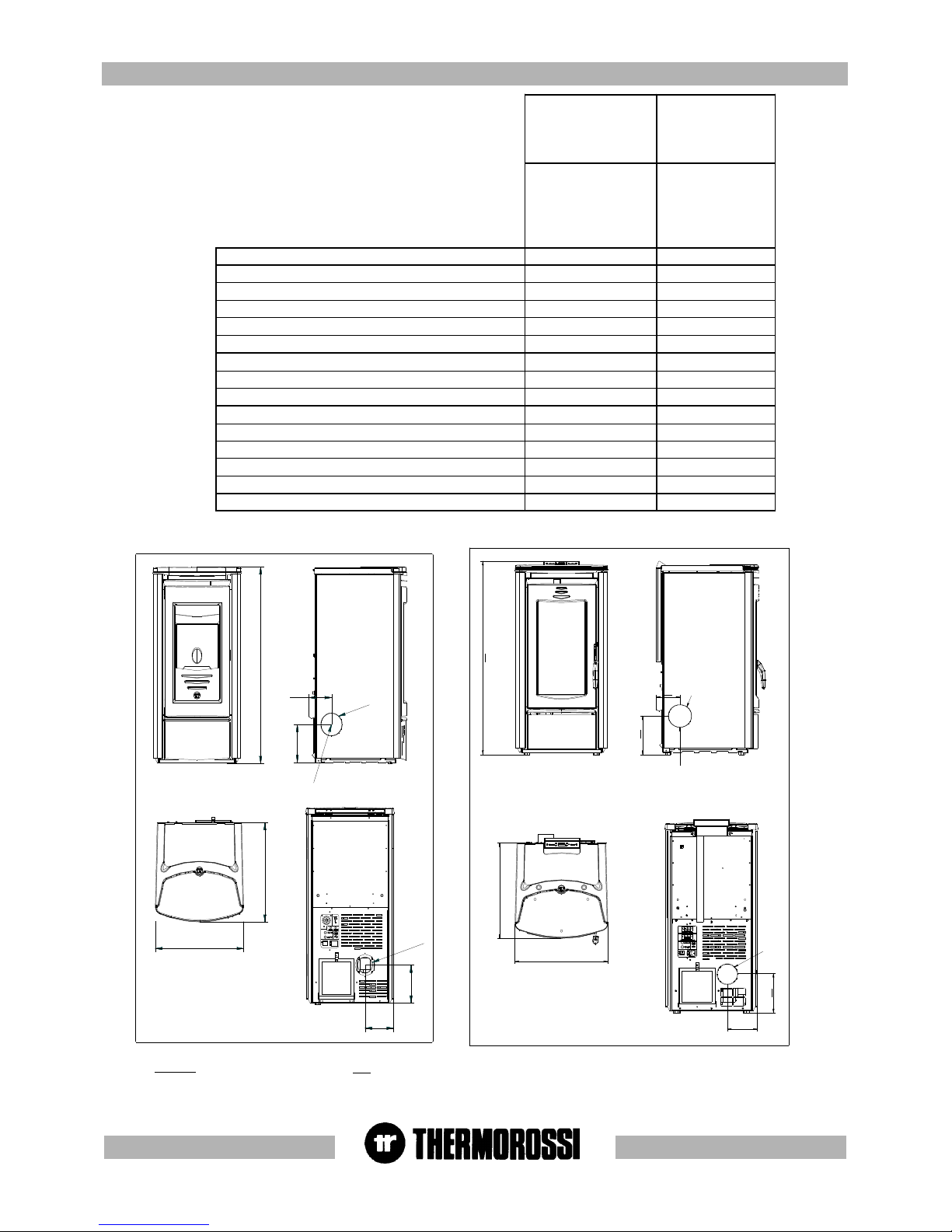
*All the data are based on the appliance fuelled with
Austrian standard O M 7135 type-approved pellets.
O 80
USCITA FUMI LATERALE SINISTRA
O 80
148
non è possibile utilizzare l'uscita fumi laterale
Nella versione con rivestimento in ceramica
117
184
484
460
184
992
KEY
LEFT SIDE SMOKE OUTLET
The side smoke outlet cannot be used for
the model with the ceramic casing
Ecotherm 3001
Easy-Metalcolor
Ecotherm 3001
Ceramic
element
Ecotherm 3001
Thermocomfort
Easy-Metalcolor
Ecotherm 3001
Thermocomfort
Ceramic
element
Height (mm) 955 955
Depth (mm) 484 484
Width (mm) 460 460
Weight (Kg) 118 143
Rated power (Kw) 9,2 9,2
Reduced rated power (Kw) 2,5 2,5
Consumption min/max (Kg/h) 0,7 – 2,3 0,7 – 2,3
Smoke outlet tube D. (mm) 80 80
Min. draught at rated power (Pa) 12 12
Hopper capacity (Kg) approx. 16 approx. 16
Average smoke temp. at rated power (° C) 180 180
Smoke flow at rated power (g/sec) 5,5 5,5
Electricity 220 V 50 HZ 220 V 50 HZ
Max electrical consumption 1,17 A – 270 W 1,17 A – 270 W
Min electrical consumption 0,34 A – 70 W 0,34 A – 70 W
LEGENDA
USCITA FUMI LATERALE SINISTRA
Nella versione con rivestimento in ceramica
non è possibile utilizzare l'uscita fumi laterale
pg. 6
33
33
3
GENERAL DESCRIPTIONGENERAL DESCRIPTION
GENERAL DESCRIPTIONGENERAL DESCRIPTION
GENERAL DESCRIPTION
3.13.1
3.13.1
3.1
OPERAOPERA
OPERAOPERA
OPERA
TING TING
TING TING
TING
TECHNOLTECHNOL
TECHNOLTECHNOL
TECHNOL
OGYOGY
OGYOGY
OGY
•Your heater has been built to fully satisfy all your heating and practical requirements. Top-grade components and functions managed with
microprocessor technology guarantee high reliability and optimal performance.
3.23.2
3.23.2
3.2
PELLETSPELLETS
PELLETSPELLETS
PELLETS
•The appliance is fuelled by pellets, that is, cylinders of compressed sawdust; this will make it possible for you to enjoy to the full the heat of the
flame without having to manually stoke the combustion. •The pellets are cylinders of compressed sawdust having a 6 mm diameter and a
maximum length of 15 mm. They have a maximum moisture content of 8%; a thermal value of 4000/4500 Kcal/Kg and a density of 620-630 Kg/
m³.
The use of fuel which does not comply with the description given above immediately voids the heater warranty.
Do not use the appliance as an incinerator, at the risk of voiding the warranty.
44
44
4
INSTINST
INSTINST
INST
ALLAALLA
ALLAALLA
ALLA
TIONTION
TIONTION
TION
4.14.1
4.14.1
4.1
HEAHEA
HEAHEA
HEA
TER LTER L
TER LTER L
TER L
OCAOCA
OCAOCA
OCA
TIONTION
TIONTION
TION
CAUTION : Always use trolleys to move the appliance and the appliance must always be in a vertical position. Follow the general guidelines set
out in paragraph 1.1 to the letter. Keep in mind that the flooring of the room in which the heater is to be installed must withstand the combined
weight of the appliance and the pellets contained in the tank.
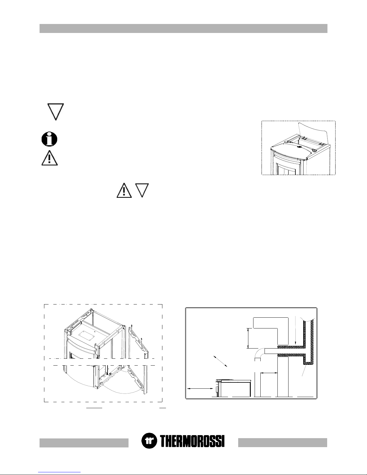
CAUTION: The room in which the appliance will operate must be adequately ventilated (minimum air intake 1300 m3/h).
The appliance must be positioned at a minimum safe distance from walls and furnishings. This distance will have to be increased considerably
if the objects surrounding the appliance are inflammable (matchboarding, furniture, curtains, picture frames, sofas, etc...).
The recommended minimum distances are illustrated in the drawing below on the right. Installation in the vicinity of heat-sensitive materials is only
permitted if suitable insulating protection is placed between the object and the appliance (ref. Uni 10683). Adjust the mounting feet to obtain a
slight gap between heater and flooring to ensure that the heater is not resting directly on the floor. It is advisable to interpose a floor protector
plate between the heater and the floor if the latter is made of wood or other combustible material.
4.1.14.1.1
4.1.14.1.1
4.1.1
MOUNTING MET MOUNTING MET
MOUNTING MET MOUNTING MET
MOUNTING MET
ALAL
ALAL
AL
COLCOL
COLCOL
COL
OR CASINGOR CASING
OR CASINGOR CASING
OR CASING
Once the heater has been positioned the next step is to install the side panels and the top ceramic panel as shown in the image below on the
left.The mounting sequence is as follows:
- Remove the top cast iron cover
- Insert the side panel position the bottom holes on the folds in the base and fix the 2 top screws (Figure 1A).
- Then mount the top cover and the ceramic panel.
Remember that the heater must be completely cooled down before the side panel can be cleaned with a soft cloth and water.
The casing on the Easy model is factory-mounted before delivery .
Figura 1 A
Figura 1A
3.33.3
3.33.3
3.3
THE FEEDBOTHE FEEDBO
THE FEEDBOTHE FEEDBO
THE FEEDBO
XX
XX
X
The feedbox is situated in the top part of the heater. The maximum load capacity of the tank is
approximately 16 Kg, but varies according to the specific weight of the pellets. The manufacturer
recommends emptying the hopper and vacuuming the screw feeder zone once a
month and during the summer period. Take special care when loading the hopper as
the screw feeder at its base is in motion.
450 mm SE MATERIALE COMBUSTIBILE
450 mm SE MATERIALE COMBUSTIBILE
ISOLANTE TERMICO
2
0
0
m
m
S
E
M
A
T
E
R
I
A
L
E
C
O
M
B
U
S
T
I
B
I
L
E
200 mm SE MATERIALE
COMBUSTIBILE
Tee ispezionabile
KEY
Heat insulating material
Inspectable Tee element
200/450 mm if the material is combustible
Figure / Detail
LEGENDA
Isolante termico
T ispezionabile
200/450 mm se materiale combustibile
Figura / Dettaglio
pg. 7
Figura 4
Figura 3
Figura 1
A
DETTAGLIO A
Figura 2
A
B
C
D
F
E
G
H
SID
SSD
4.1.24.1.2
4.1.24.1.2
4.1.2
MOUNTING CERAMIC CASING MOUNTING CERAMIC CASING
MOUNTING CERAMIC CASING MOUNTING CERAMIC CASING
MOUNTING CERAMIC CASING
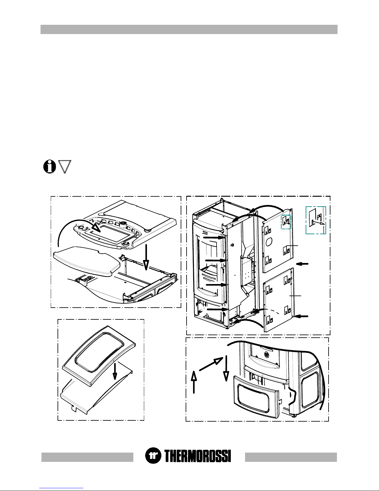
The next step, after positioning the heater, is to mount the ceramic casing as illustrated in the figures below.
Carry out the following operations:
- Remove the top cast iron cover ( Figure 1).
- Mount the right ceramic panel supports (figure 2) following the procedure set out below:
Undo screws A and B and remove them momentarily. Fix support SID by firstly inserting the bottom folds on the seat of the heater base, next
re-insert and fasten screws A and B. Undo screws C and B and remove them momentarily. Fix support SSD then re-insert and fasten screws
C and D. Next screw in screws E and F provided. Screw in screws G and H provided. If the holes for the screws are not already present drill
holes using a d.3.5 bit.Bend the tabs slightly (indicated in detail A of Figure 2) outwards from the heater. Next fix the side ceramics to the supports
by securing them to the bent tabs. Next mount the left ceramic panel supports using the same procedure as described above for the right
ceramic panel supports (Figure 2).
Next attach the side ceramic panels to the supports.
- Fix the lower front ceramic panel to its support (Figure 3) with the silicone provided; degrease and clean the ceramic panel support before
gluing the parts to ensure optimal adhesion. Leave the ceramic panel in the position illustrated in Figure 3 and wait 24 hours before handling it.
- Next fasten the lower ceramic panel to the heater following the instructions set out in Figure 4.
- Lastly position ceramic top ( Figure 1).
Special care must be taken when handling and mounting the ceramics in order to prevent breakages that are not covered by
warranty.
Small imperfections on the surfaces of the ceramics such as: dimples, shivering and slight colour variations are normal
characteristics of handcrafted ceramics which make each piece unique.
pg. 8
55
55
5
DESCRIPTION OF ECOTHERM 3001 CONTROLSDESCRIPTION OF ECOTHERM 3001 CONTROLS
DESCRIPTION OF ECOTHERM 3001 CONTROLSDESCRIPTION OF ECOTHERM 3001 CONTROLS
DESCRIPTION OF ECOTHERM 3001 CONTROLS
5.15.1
5.15.1
5.1
DESCRIPTION OF GREY HANDHELD RADIO CONTRDESCRIPTION OF GREY HANDHELD RADIO CONTR
DESCRIPTION OF GREY HANDHELD RADIO CONTRDESCRIPTION OF GREY HANDHELD RADIO CONTR
DESCRIPTION OF GREY HANDHELD RADIO CONTR
OL OL
OL OL
OL
AND HEAAND HEA
AND HEAAND HEA
AND HEA
TER REAR PTER REAR P
TER REAR PTER REAR P
TER REAR P
ANELANEL
ANELANEL
ANEL
INTRODUCTION
The handheld radio control is the control instrument for your heater that will permit you to manage Ecotherm and its functions. The radio
control is a user-friendly way of interacting with the main heater settings and, when required, of accessing the various other control
commands. In both cases the Manufacturer recommends you read the following pages carefully so that you will know how to make the best
use of your heater. Keep in mind that radio wave transmissions can be affected by the surrounding environment: the presence of thick walls
can reduce the transmission that normally extends to 6-7 metres.
CAUTION: to guarantee optimal data transmission it is advisable to always place the radio control in its support in a vertical
position.
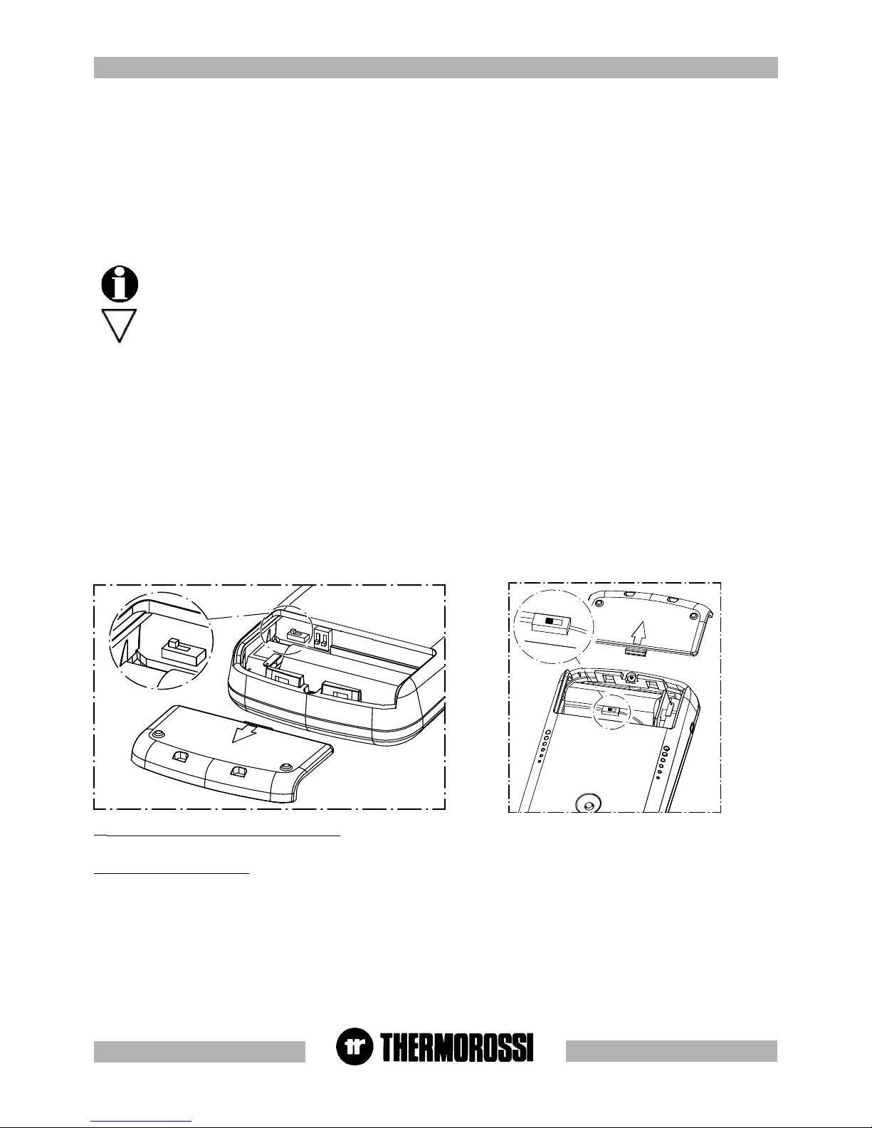
The following operations must be carried out the first time the heater is started up :
- Turn the switch inside the battery compartment to ON (see drawing below)
- Connect the radio control by means of the battery charger supplied to the power line, ( it must be recharged for
at least 5 days: see para. 8.3), as the rechargeable batteries could be partially or completely flat). Leave the radio
control connected at all times, by means of the battery charger, to the power supply line. The heater must be
energised and the switch turned to position "1". At the end of the winter season it is mandatory to switch off the
radio control completely, by means of the switch situated inside the battery compartment, in order to preserve
the life of the batteries. The batteries are guaranteed for 6 months. When the batteries are exhausted dispose of
them safely. It is normal for the temperature sensor to detect temperatures which are slightly different to the
real ones: variations caused by the environment in which the radio control is positioned.
(1) Insert on/off and flame adjustment button When you press this button the appliance (10) switches to ON/ RUNNING/ OFF. Press
repeatedly to activate up to 5 bars (7) and the AUTO indicator is activated (8 automatic) .
(2) Ventilation setting button Press this button to set the desired level of ventilation: up to a maximum of 6 speeds are available, indicated by
the lighting of the corresponding bar (6).
5.1.2 ROOM TEMPERATURE THERMOSTAT OPERATION
When the AUTO function is activated the temperature value detected by the temperature sensor (5) installed in the radio control is updated at
regular intervals.During the start up phase the temperature value is not updated. The temperature value transmitted to the heater does not change
the instant there is a sudden change in the room temperature but it is updated regularly through the DATA ANALYSIS function. It is normal for the
temperature sensor to detect temperatures which are slightly different to the real ones: these variations are caused by the environment in which
the radio control is positioned and by the prolonged use of the display.
O
n
O
n
O
n
O
n
1
22
O
N
O
N
O
N
5.1.1 HANDHELD RADIO CONTROL
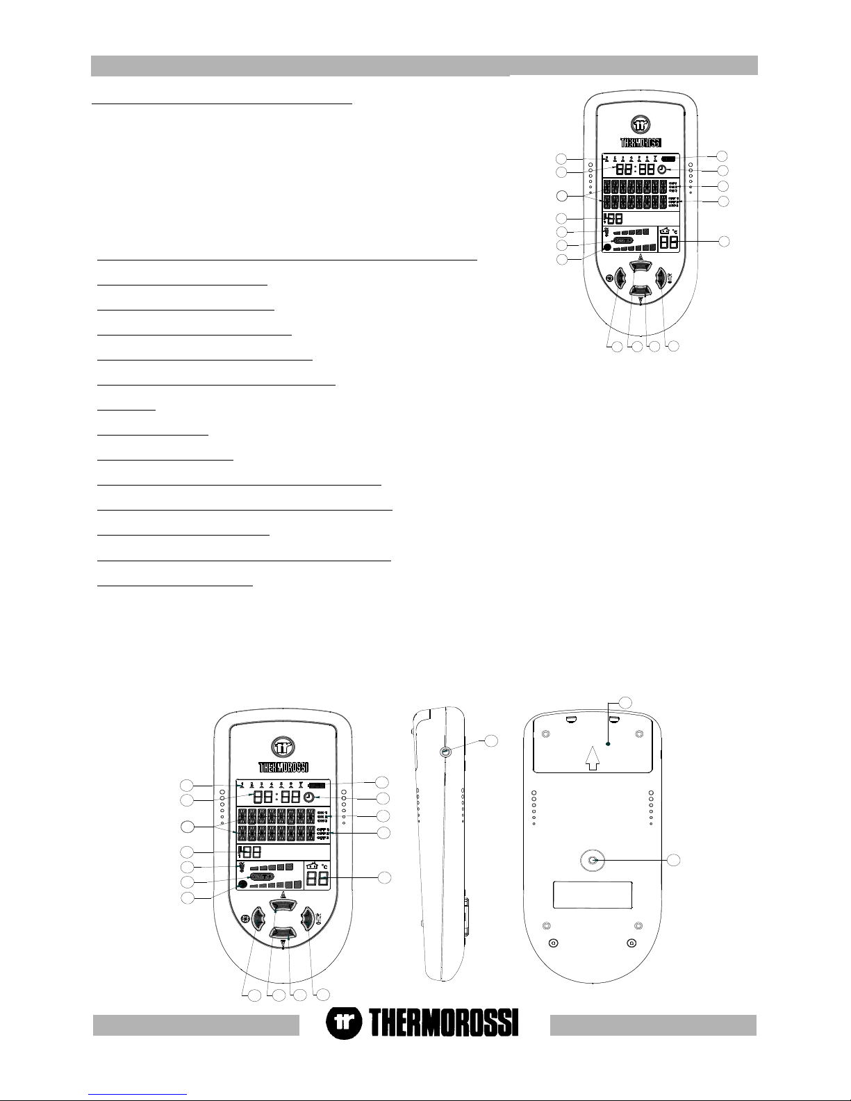
A description of the buttons and indicators on the radio control follows:
The radio control consists of a plastic shell on which is installed a backlit LCD display with control buttons, interface card and
rechargeable batteries: the backlighting switches off temporarily during use in order to reduce energy consumption which consequently
extends the duration of the charge. There are two main control pushbuttons marked with the ventilation symbol (2) and the symbol of
the flame (1). The flame button (1) sets the heater power, there are a possible 5 power levels displayed by the 5 bars progressively
coming on in sequence (7). You can select the AUTOMATIC mode displayed by the text word AUTO (see paragraph 5.9 ). The shutdown
cycle appears on the display when all the power bars are off. The fan button (2) controls the ventilation of the heater. The heater
activates when the temperature exceeds 42 °C. The ventilation can be set up to 6 speed levels: when the heater is on the ventilation
cannot be switched off.
Therefore, in brief, the two buttons function as follows:
pg. 9
18
1
2
3
4
5
6
7
8
9
10
11
12
13
14
15
16
17
19
1
2
3
4
5
6
7
8
9
10
11
12
13
16
15
14
(3) (4) Auxiliary buttons for temperature setting
Press button 3 to lower the temperature. Press button 4 to raise the temperature level set in
Aladino. As is explained below they are only functional if the AUTO cycle is selected. The set
temperature appears in zone 9 of the display.
The room temperature, however, appears in zone 5 of the display. In this operating cycle the
ventilation and power self-regulate according to the set temperature and the temperature
detected in the display. It is not possible to set the air flow discharging from the heater at any
desired temperature because it is autonomously established by the heater according to the
ambient temperature. If the AUTO function is not activated the temperature value set with buttons
3 and 4 is ignored.
5.1.35.1.3
5.1.35.1.3
5.1.3
Indicators of the handheld radio controlIndicators of the handheld radio control
Indicators of the handheld radio controlIndicators of the handheld radio control
Indicators of the handheld radio control
(5) "Room temperature detected by the radio control's sensor indicator
(6) "Ventilation level" indicator
(7) “Combustion level” indicator
(8) "AUTO" CYCLE ACTIVE indicator
(9) “Room temperature setting" indicator : this is the room temperature that you wish to reach by means of buttons 3 and 4.
(10) Display zone where the following appear: operating phases, programming, MENU …
(11) Clock
(12) Day of the week
(13) Battery charge level
(14) “Chronothermostat enabled-disabled” indicator
(15) (16) On-off indicators for the programming phase
(17) Battery charger connection
(18) “Code selector” and “Battery compartment” cover
(19) “MENU” selection button To access the main menu press the button marked 19. Press button 19 repeatedly to scroll the
adjustment, setting and programming windows (see para. 5.2 , 5.3 , 5.4 , 5.5 , 5.6 , 5.7) . This button can also carry out DATA
ANALYSIS functions: fundamental control function for updating data.
After having carried out the DATA ANALYSIS all the data will be updated: it is normal for the temperature sensor to detect temperatures
which are slightly different to the real ones: variations caused by the environment in which the radio control is positioned.
To exit the main menu without having to scroll all the possible adjustments/ functions, simply press button (1) to return to the heater
operating status.
pg. 10
28
27
26
21
25
29
23
24
22
20
5.1.4 HEA5.1.4 HEA
5.1.4 HEA5.1.4 HEA
5.1.4 HEA
TER REAR PTER REAR P
TER REAR PTER REAR P
TER REAR P
ANELANEL
ANELANEL
ANEL
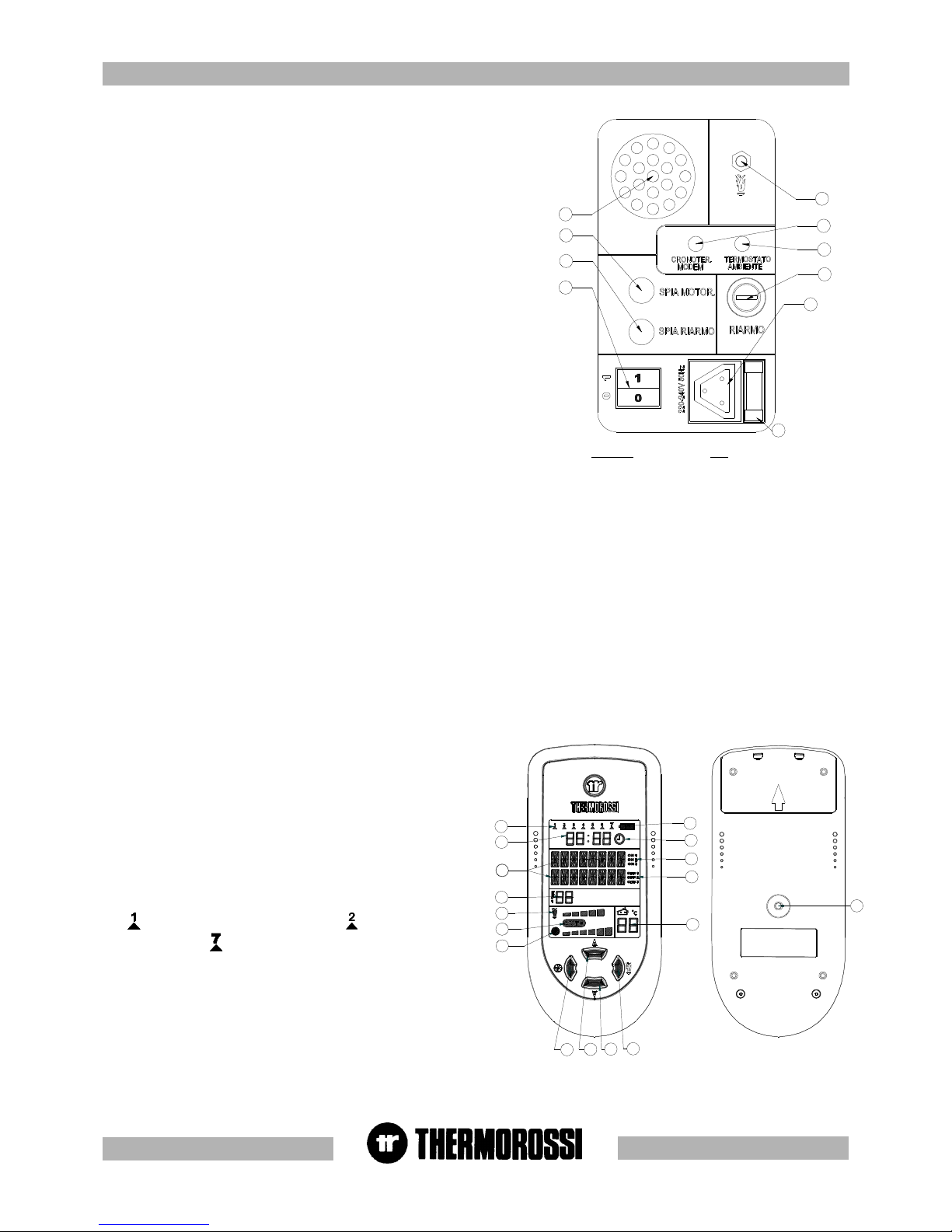
The rear panel integrates the radio control.
A description of the functions of the buttons and LEDs on the rear panel of the
heater:
(20) Insert on/off and flame adjustment button
By pressing this button you can use the heater even without the radio control.
Press button (20) repeatedly to increase the combustion power, whereas the
ventilation level is adjusted automatically according to the selected combustion
power. One or more acoustic signals correspond to each power step
selected:
-1 power bar -- 1 acoustic signal
-2 power bars -- 2 acoustic signals
-........................................................................
-5 power bars -- 5 acoustic signals
If you press once again the acoustic signals will not sound: this means that
after 5 seconds the heater will set itself in OFF mode and consequently shut
down. It is not possible to select the AUTO cycle.
21 Loudspeaker for voice alarms/information: the heater gives
information on its status and any active alarms through this loudspeaker.
22 Power outlet for additional room temperature connection.(see
para. 7.1)
(additional room temperature thermostat not supplied)
23 Power outlet for additional chronothermostat connection.(see
para. 7.2)
(additional chronothermostat not supplied)
24 Overtemperature thermostat button cap
In the event of overtemperature this safety thermostat stops the loading of pellets. When it is activated LED 27 comes on. To restart the
heater you need to wait until it cools down, then verify the cause for the overheating, remove the cause, unscrew the protective cap and
press the button (24) .
25 Electrical power outlet 220-240V 50Hz
26 Loading motor test LED.
The light must come on when the pellet screw feeder starts .
27 Reset thermostat tripped indicator light. This LED comes on when the reset thermostat is activated.
28 Main switch 0-1
29 General fuse 3.15 A
19
3
4
2
1
10
9
8
7
6
12
11
16
5
15
14
13
5.2 D5.2 D
5.2 D5.2 D
5.2 D
AA
AA
A
Y Y
Y Y
Y
AND AND
AND AND
AND
TIME SETTINGTIME SETTING
TIME SETTINGTIME SETTING
TIME SETTING
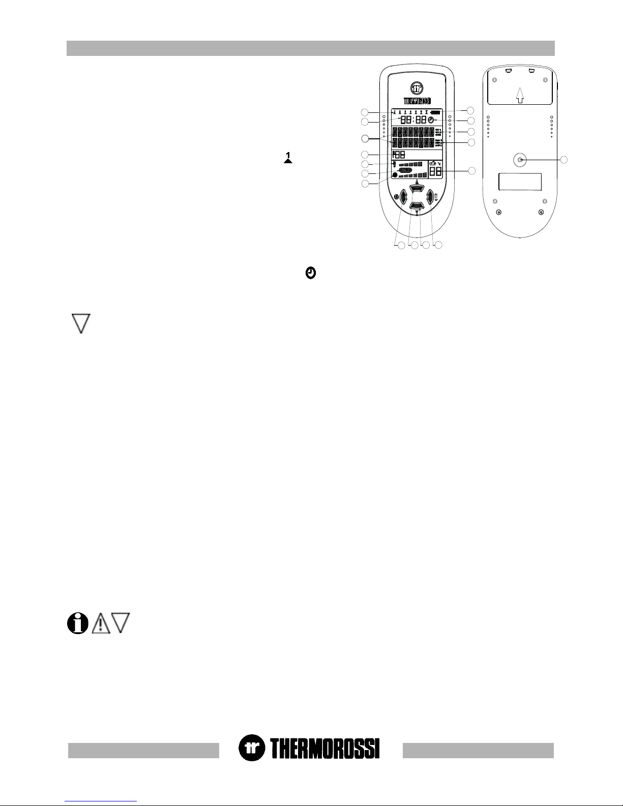
The heater must be energised and the switch at the back turned to
position "1"(see image in top right corner).
To set the clock and the day of the week carry out the procedures
described below. Press the button (19) on the back of the radio
control repeatedly until the word TIME appears.
To set the day press the button (2) . The word DAYS will appear on
the display, and the indicator (12) will start to blink. Press the button
(3) and/or (4) to set the number that corresponds to the current day.
The symbol corresponds to Monday , the symbol to Tuesday
..... and the symbol to Sunday. To confirm the selection press the
button (1). Next the word HOUR will appear on the display, and the
hour indicator (11) will start to blink. Press button (3) and/or (4) to set
the current time. To confirm the selection press the button (1). Next
the word MINUTES will appear on the display and the minute
indicator (11) will start to blink. Press buttons (3) and/or (4) to set the
current minutes . To confirm the selection press the button (1). The
day and time setting is now completed : at this point the heater
operating status will appear on the display.
KEY
Room temperature thermostat
Chronothermostat - modem
Motor LED
Reset LED
Reset
LEGENDA
Termostato ambiente
Cronotermostato - modem
Spia Motor
Spia riarmo
Riarmo
pg. 11
19
3
4
2
1
10
9
8
7
6
12
11
16
5
15
14
13
5.3 ON/OFF PROGRAMMING.5.3 ON/OFF PROGRAMMING.
5.3 ON/OFF PROGRAMMING.5.3 ON/OFF PROGRAMMING.
5.3 ON/OFF PROGRAMMING.
The heater must be energised and the switch at the back in position "1".
The weekly programming can be executed with the help of the handheld radio
control. It is possible to set up to 3 on-off cycles for each day from Monday to
Sunday. To access the programming mode press the button (19) on the back of
the radio control repeatedly until the word CRONO appears.
Press button (3) or (4) to enable/disable the program setting ( symbol (14)
present / absent): this function is useful if you wish to disable the established
weekly program setting. To program the heater you need to access the
chronothermostat function by pressing the button (2): the LED (12) comes on
(this indicates that Monday, the first day of the week, is being programmed). The
text ON1 of the indicator (15) comes on and the word HOURS appears on the
display. Press button (3) and/or (4) to enter the hour of the first cycle start time.
To confirm the selection press the button (1). The word MINUTES will appear on
the display. Press button (3) and/or (4) to enter the minutes of the first cycle
start time. To confirm the selection press the button (1). Next the text OFF1
(indicator (16) will appear on the display. Proceed using buttons (3), (4) and (1)
as indicated above to set HOURS and MINUTES for the cycle end time. At this
point the first on-off cycle for Monday has been entered. It is then possible to set
the second on-off cycle for Monday (indicated by the texts ON2 and OFF2) and
the third on-off cycle for Monday (indicated by the texts ON3 and OFF3) . Now program the on-off cycles for the remaining days of the week
up to and including Sunday. When the programming mode is active ( symbol present) the minimum operating value at cycle on
(combustion power - ventilation speed ) is the same minimum operating value that was set before the last cycle off.
If the second on-off cycle is not required simply set the ON2 time as 00:00 and the OFF2 time as 00:00 .
In the event of a programmed cycle on always ensure that the brazier is clean and seated correctly in its lodging: failure to keep the
brazier clean can reduce the life of the spark plug.
5.4 5.4
5.4 5.4
5.4
VV
VV
V
OICE INFORMAOICE INFORMA
OICE INFORMAOICE INFORMA
OICE INFORMA
TION TION
TION TION
TION
VV
VV
V
OLOL
OLOL
OL
UME CONTRUME CONTR
UME CONTRUME CONTR
UME CONTR
OLOL
OLOL
OL
The heater must be energised and the switch at the back turned to position "1".
Your heater informs you on its operating status and on any problems that could arise by means of voice messages . Select the volume level
for the voice messages by carrying out the following procedure. When the insert is in the POWER OFF, POWER ON or RUNNING status
simply press the button (19) until the word VOLUME appears on the display (10). Press button (2) and the word SELECT appears on the
display: the introductory music plays. Press button (4) repeatedly and the + symbol appears (to increase the volume) .
Press button (3) repeatedly and the - symbol appears (to lower the volume). To confirm the volume selection press the button (1). The heater
then returns to its previous POWER ON or RUNNING or POWER OFF status.
5.5 OPERA5.5 OPERA
5.5 OPERA5.5 OPERA
5.5 OPERA
TING LEVEL SETTINGTING LEVEL SETTING
TING LEVEL SETTINGTING LEVEL SETTING
TING LEVEL SETTING
The heater must be energised and the switch at the back turned to position "1".
Your appliance is delivered with an excellent program installed that favours combustion yield; the program is called Level 1.
If you are using pellets with a higher than normal incidence of residues after combustion in the brazier, alternative levels may be selected:
Level 2 : this program increases the smoke suction unit speed acceleration.
Level 3 : this program increases the suction unit speed to a greater degree than level 2.
Level 0 : when using lightly-compressed pellets and/or flue outlets with very high vacuum, over 2 mm water column.
The pellet consumption value is not affected by the operating level settings.
Select the required level by acting as follows:
Press the (19) button on the back of the radio control repeatedly until the text indicating the preset heater level appears on the display (Level
1 or Level 2 or Level 3 or Level 0). Press the button (2) and the word SELECT appears on the display (10). To change the operating level
hold down button (3) and press button (4).
By holding down button (3) and pressing button (4) repeatedly the level changes in the following sequence: Level 2... Level 3...Level
0...Level 1.., next press button (1) to confirm the selected level.
The level selection can be made with the heater OFF or ON. If the change is made while the insert is running the
difference in the flame will be apparent. It is mandatory to pay particular care when selecting the most appropriate
operating cycle for your installation. After the selection of the operating cycle a thorough cleaning of the brazier is
mandatory.
5.6 LANGUAGE SELECTION5.6 LANGUAGE SELECTION
5.6 LANGUAGE SELECTION5.6 LANGUAGE SELECTION
5.6 LANGUAGE SELECTION
The heater must be energised and the switch at the back turned to position "1".
Press the MENU' button (19) repeatedly until the word ITALIAN appears on the display (10) . To change the display language proceed as
follows: Press button (2) and the SELECT ITALIAN text appears on the display. Press button (4) repeatedly to select German, English,
French. Once you have selected the desired language press button (1) : the radio control carries out a data analysis, that is, an update of
the new language.
 Loading...