

THERMOROSSI ECOTHERM 3001, ECOTHERM 3001 THERMOCOMFORT Installation, Use And Maintenance Manual
Page 1

INSTALLATION, USE AND MAINTENANCE GUIDE
ECOTHERM 3001
ECOTHERM 3001 THERMOCOMFORT
www.thermorossi.com
HEATING TECHNOLOGY AND INNOVATION
Page 2

pg. 2
C O N T E N T SC O N T E N T S
C O N T E N T SC O N T E N T S
C O N T E N T S
DECLARATION OF CONFORMITY
1. INTRODUCTION .................................................................................................................................................................................
1.1 General guidelines .............................................................................................................................................................
1.2 Safety guidelines ................................................................................................................................................................
1.3 Standards and recommendations .....................................................................................................................................
1.4 Transportation and storage................................................................................................................................................
2. TECHNICAL CHARACTERISTICS ....................................................................................................................................................
3. GENERAL DESCRIPTION..................................................................................................................................................................
3.1 Operating technology .........................................................................................................................................................
3.2 Pellets .................................................................................................................................................................................
3.3 The feedbox ........................................................................................................................................................................
4. INSTALLATION ..................................................................................................................................................................................
4.1 Heater location................................................................................................................................................................
4.1.1 Mounting metalcolor casing. .............................................................................................................................................
4.1.2 Mounting ceraming casing..............................................................................................................................................
5. DESCRIPTION OF "ECOTHERM 3001" CONTROLS .................................................................................................................
5.1 Description of grey handheld radio control and heater rear panel.................................................................................
5.2 Day and time setting .........................................................................................................................................................
5.3 On/Off programming..........................................................................................................................................................
5.4 Voice information volume control .....………………..........................................................................................................
5.5 Operating level setting..............................……………......................................................................................................
5.6 Language selection...........................................................................................................................................................
5.7 Data analysis.....................................................................................................................................................................
5.8 Transmission-reception alarms........................................................................................................................................
5.9 Automatic / Manual operating mode .................................................................................................................................
5.10 Transmission code setting ...............................................................................................................................................
5.11 Care and maintenance of the radio control.......................................................................................................................
5 A. DESCRIPTION OF "ECOTHERM 3001 THERMOCOMFORT" CONTROLS........................................................................
5A.1 Description of control panel and heater rear panel ..........................................................................................................
5A.2 Day and time setting .........................................................................................................................................................
5A.3 On/Off programming.........................................................................................................................................................
5A.4 Operating level setting.......................................................................................................................................................
6. USE OF THE "ECOTHERM 3001" HEATER...................................................................................................................................
6.1 Switching on the heater……………………………………………………........................................................................
6.2 Adjusting the heater’s combustion...............................................................................................................................
6.3 Filter..............................................................................................................................................................................
6 A. USE OF THE "ECOTHERM 3001 THERMOCOMFORT" HEATER..........................................................................................
6A.1 Switching on the heater…………………………………………………….......................................................................
6A.2 Adjusting the heater's combustion and ventilation......................................................................................................
6A.3 Infrared control.............................................................................................................................................................
6A.4 Operation of the white handheld radio control (optional)............................................................................................
6A.5 Filter.............................................................................................................................................................................
7. ADDITIONAL ROOM TEMPERATURE THERMOSTAT (not supplied) FOR "ECOTHERM 3001" /
ADDITIONAL CHRONOTHERMOSTAT (not supplied) FOR "ECOTHERM 3001" ...........................................................
7.1 Operating with the additional room temperature thermostat (not supplied)...…………..............................................
7.2 Operating with the additional chronothermostat (not supplied)..................................................................................
7 A. ADDITIONAL ROOM TEMPERATURE THERMOSTAT (not supplied) FOR "ECOTHERM 3001 THERMOCOMFORT" /
ADDITIONAL CHRONOTHERMOSTAT (not supplied) FOR "ECOTHERM 3001 THERMOCOMFORT" .....................
7A.1 Operating with the additional room temperature thermostat (not supplied)...…………..............................................
7A.2 Operating with the additional chronothermostat (not supplied)..................................................................................
Page 3

pg. 3
THERMOROSSI S.p.A.
Via Grumolo. 4
36011 ARSIERO
tel. 0445.741310
fax 0445.741657
"CE" DECLARA TION OF CONFORMITY
In accordance with the following directives:
European Directive 73/23/EEC and its amending directive 93/68/EEC
89/336/EEC and its amending directives 93/68/EEC
92/31/EEC
93/97/EEC
Thermorossi S.p.A., Via Grumolo 4 - ARSIERO (VI), declares that the heaters of the ECOTHERM series have been designed and manufactured
in compliance with the safety requirements of the standards for EC marking.
This declaration refers to the entire range of the specified series.
Ecotherm 3001 complies with EN 14785: 2006.
ARSIERO , 03 May 2010
THERMOROSSI S.p.A.
8. CLEANING AND MAINTENANCE ......................................................................................................................................................
8.1 Foreword .............................................................................................................................................................................
8.2 Cleaning and maintaining the heater……….…………………………………………………….........................................
8.3 Charging the handheld radio control battery …………………………….........................................................................
8.4 Replacing the battery in the infrared remote control (applies only to ECOTEHRM 3001
THERMOCOMFORT)....................................................................................................................................................
8.5 Replacing the buffer battery of the control panel (applies to ECOTHERM 3001 THERMOCOMFORT) ...................
9. SMOKE DISCHARGE TUBE ...............................................................................................................................................................
9.1 Ventilation of the rooms...…………........................................……… ….........................................................................
9.2 Smoke outlet...................................................................................................................................................................
10. VOCAL ALARMS FOR ECOTHERM 3001.................................................................................................................................
10A. ALARMS FOR ECOTHERM 3001 THERMOCOMFORT ........................................................................................................
11. ELECTRICAL WIRING DIAGRAM FOR ECOTHERM 3001....................................................................................................
11A. ELECTRICAL WIRING DIAGRAM FOR ECOTHERM 3001 THERMOCOMFORT...............................................................
12. INFORMATION FOR THE SKILLED TECHNICIAN………………...................................................................................................
12.1 Main components and their operation...........................................................................................................................
12.2 Useful advice for installation and operation..................................................................................................................
12.3 Troubleshooting problem-cause-solution (applies to ECOTHERM 3001)..................................................................
12.4 Troubleshooting problem-cause-solution (applies to ECOTHERM 3001 THERMOCOMFORT) .............................
13 SPARE PARTS
13.1 Spare parts for " Ecotherm 3001 " and " Ecotherm 3001 Thermocomfort ".................................................................
13.2 Spare parts for " Ecotherm 3001 " and " Ecotherm 3001 Thermocomfort ".................................................................
13.3 Spare parts for " Ecotherm 3001 " and " Ecotherm 3001 Thermocomfort ".................................................................
13.4 Spare parts for " Ecotherm 3001 " and " Ecotherm 3001 Thermocomfort ".................................................................
13.5 Spare parts for " Ecotherm 3001 "................................................................................................................................
13.6 Spare parts for " Ecotherm 3001 Thermocomfort "......................................................................................................
Page 4
pg. 4
11
11
1
INTRODUCTIONINTRODUCTION
INTRODUCTIONINTRODUCTION
INTRODUCTION
1.11.1
1.11.1
1.1
GENERAL GUIDELINESGENERAL GUIDELINES
GENERAL GUIDELINESGENERAL GUIDELINES
GENERAL GUIDELINES
This installation, use and maintenance guide is an integral and essential part of the product and must be kept by the user . Before commencing with
the installation, use and maintenance of the product, carefully read all the instructions contained in this booklet. At the time of installation of the
appliance all local regulations, including those that refer to national and European regulations, must be observed. The Manufacturer recommends
carrying out all the maintenance operations described in this manual.
This appliance must only be used as intended by the manufacturer. Any other use is considered incorrect and therefore hazardous; consequently,
the user shall be totally liable for the product if used improperly. Installation, maintenance and repairs must be carried out by personnel with
professional qualifications and in compliance with current regulatory standards and in accordance with the instructions of the manufacturer of
the appliance. Use only original spare parts.
Incorrect installation or poor maintenance could injure or damage people, animals or things; in this case the manufacturer shall be relieved of all
responsibility. Before commencing any cleaning or maintenance operation ensure that the appliance has been disconnected from the mains
power supply by means of the main system switch or some other disconnecting device installed upstream from the appliance. The product must
be installed in locations suitable for fire-fighting and furnished with all the services (power and outlets) which the appliance requires for a correct
and safe operation. Any repairs or actions carried out on any systems, components or internal parts of the appliance, or on any of the
accessories supplied with it, that are not specifically authorised by Thermorossi s.p.a, will automatically void the warranty and the manufacturer's
responsibility, pursuant to D.P.R. 224 of 24/05/1988, art. 6/b . Use only original Thermorossi spare parts. If the appliance is sold or transferred to
another user ensure that the guide is handed over with it.
Thermorossi S.p.A. maintains the author’s rights on these service instructions.
The information in this booklet may not be reproduced or given to third parties or used for competitive purposes without the
appropriate authorization.
1.2 SAFETY GUIDELINES1.2 SAFETY GUIDELINES
1.2 SAFETY GUIDELINES1.2 SAFETY GUIDELINES
1.2 SAFETY GUIDELINES
PERSONAL INJURY
This safety symbol identifies important messages throughout the manual. Read the information marked by this symbol carefully
as non-observance of this message can cause serious injury to persons using the heater.
DAMAGE TO PROPERTY
This safety symbol identifies messages or instructions that are fundamental for the heater and system to function well. To avoid
serious damage to the heater adhere strictly to these instructions.
INFORMATION
This symbol indicates important instructions for good functioning of the heater. If this information is not correctly observed, the
performance of the heater and/or system will not be satisfactory.
1.41.4
1.41.4
1.4
TRANSPORTRANSPOR
TRANSPORTRANSPOR
TRANSPOR
TT
TT
T
AA
AA
A
TION TION
TION TION
TION
AND STAND ST
AND STAND ST
AND ST
ORAORA
ORAORA
ORA
GEGE
GEGE
GE
TRANSPORTATION AND HANDLING
The heater body must always be in a vertical position when handled and exclusively by means of trolleys. Take special care to protect the
electric panel, the glass, the ceramics and all the fragile parts from mechanical impact which could damage them and their correct
functioning.
STORAGE
The heater must be stored in a humid-free environment and sheltered from the weather; do not place the heater directly on the floor. The
Company denies all responsibility for damage caused to wood floors or floors made from any other material.
It is inadvisable to store the heater for long periods of time.
1.31.3
1.31.3
1.3
STST
STST
ST
ANDAND
ANDAND
AND
ARDS ARDS
ARDS ARDS
ARDS
AND RECOMMENDAND RECOMMEND
AND RECOMMENDAND RECOMMEND
AND RECOMMEND
AA
AA
A
TIONSTIONS
TIONSTIONS
TIONS
NORMATIVE REFERENCES :national and international standards used as reference guides in the following manual for the design, industrialization
and production of the products:
- European directive 73/23/EEC - Standard CEI 61/50 - European directive 93/68/EEC
- Standard CEI EN 60204 - European directive 89/336/EEC - Standard CEI 64-8 (IEC 364)
- European directive EN 14785: 2006
RECOMMENDATIONS
Before using the appliance, carefully read every section of this instruction manual as knowledge of the information and the regulations contained
in it are essential for a correct use of the appliance.
The entire operation concerning the connection of the electric panel must be carried out by expert personnel; no responsibility will be accepted
for damages, even to third parties, if the instructions for installation, use and maintenance of the appliance are not followed scrupulously.
Modifications made to the appliance by the user or on his behalf, must be considered to be under his complete responsibility. The user is
responsible for all the operations required for the installation and maintenance of the appliance before and during its use.
GENERAL WARNINGS
Caution: the appliance must be connected to a system provided with a PE conductor (in compliance with the specifications of 73/23/EEC, 93/
98/EEC, concerning low voltage equipment). Before installing the appliance check the efficiency of the earth circuit of the power supply system.
Caution: the power supply line must have a section which is suitable for the power of the equipment. The cable section must in any case be no
less than 1.5 mm2. The appliance requires a power supply of 220-240 V and 50 Hz. Voltage variations 10% above the nominal value can cause
irregular operation or damage to the electrical device. Position the appliance so that the electric power plug is easily accessible. Voltage
variations less than 10% of the nominal value can cause lighting and use problems.
Apply a current regulator. Ensure that a suitable differential switch is installed upstream from the equipment.
Page 5
pg. 5
22
22
2
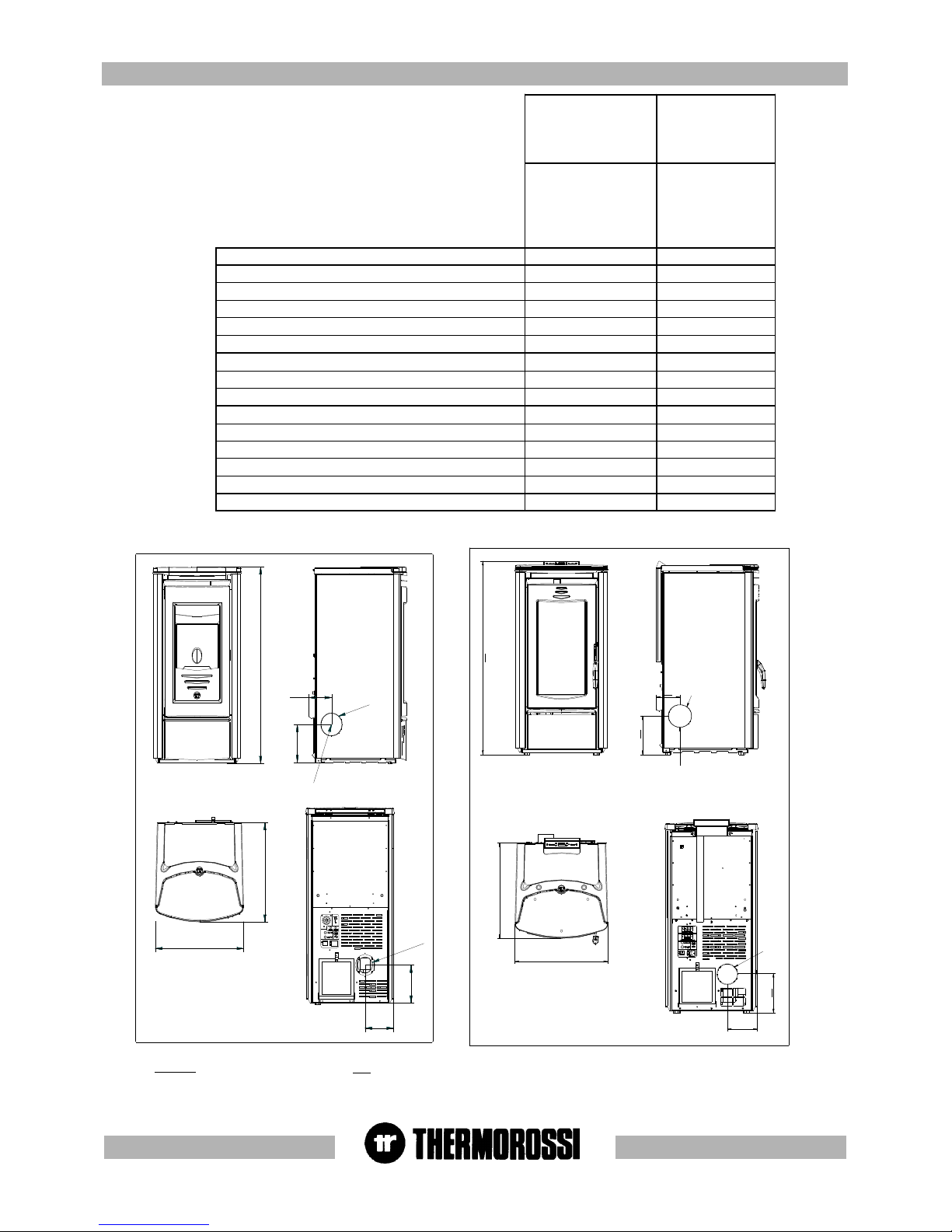
TECHNICAL CHARACTERISTICS *TECHNICAL CHARACTERISTICS *
TECHNICAL CHARACTERISTICS *TECHNICAL CHARACTERISTICS *
TECHNICAL CHARACTERISTICS *
USCITA FUMI LATERALE SINISTRA
184
118
148
184
O
8
0
O
8
0
955
484
460
Nella versione con rivestimento in ceramica
non è possibile utilizzare l'uscita fumi laterale
*All the data are based on the appliance fuelled with
Austrian standard O M 7135 type-approved pellets.
O 80
USCITA FUMI LATERALE SINISTRA
O 80
148
non è possibile utilizzare l'uscita fumi laterale
Nella versione con rivestimento in ceramica
117
184
484
460
184
992
KEY
LEFT SIDE SMOKE OUTLET
The side smoke outlet cannot be used for
the model with the ceramic casing
Ecotherm 3001
Easy-Metalcolor
Ecotherm 3001
Ceramic
element
Ecotherm 3001
Thermocomfort
Easy-Metalcolor
Ecotherm 3001
Thermocomfort
Ceramic
element
Height (mm) 955 955
Depth (mm) 484 484
Width (mm) 460 460
Weight (Kg) 118 143
Rated power (Kw) 9,2 9,2
Reduced rated power (Kw) 2,5 2,5
Consumption min/max (Kg/h) 0,7 – 2,3 0,7 – 2,3
Smoke outlet tube D. (mm) 80 80
Min. draught at rated power (Pa) 12 12
Hopper capacity (Kg) approx. 16 approx. 16
Average smoke temp. at rated power (° C) 180 180
Smoke flow at rated power (g/sec) 5,5 5,5
Electricity 220 V 50 HZ 220 V 50 HZ
Max electrical consumption 1,17 A – 270 W 1,17 A – 270 W
Min electrical consumption 0,34 A – 70 W 0,34 A – 70 W
LEGENDA
USCITA FUMI LATERALE SINISTRA
Nella versione con rivestimento in ceramica
non è possibile utilizzare l'uscita fumi laterale
Page 6
pg. 6
33
33
3
GENERAL DESCRIPTIONGENERAL DESCRIPTION
GENERAL DESCRIPTIONGENERAL DESCRIPTION
GENERAL DESCRIPTION
3.13.1
3.13.1
3.1
OPERAOPERA
OPERAOPERA
OPERA
TING TING
TING TING
TING
TECHNOLTECHNOL
TECHNOLTECHNOL
TECHNOL
OGYOGY
OGYOGY
OGY
•Your heater has been built to fully satisfy all your heating and practical requirements. Top-grade components and functions managed with
microprocessor technology guarantee high reliability and optimal performance.
3.23.2
3.23.2
3.2
PELLETSPELLETS
PELLETSPELLETS
PELLETS
•The appliance is fuelled by pellets, that is, cylinders of compressed sawdust; this will make it possible for you to enjoy to the full the heat of the
flame without having to manually stoke the combustion. •The pellets are cylinders of compressed sawdust having a 6 mm diameter and a
maximum length of 15 mm. They have a maximum moisture content of 8%; a thermal value of 4000/4500 Kcal/Kg and a density of 620-630 Kg/
m³.
The use of fuel which does not comply with the description given above immediately voids the heater warranty.
Do not use the appliance as an incinerator, at the risk of voiding the warranty.
44
44
4
INSTINST
INSTINST
INST
ALLAALLA
ALLAALLA
ALLA
TIONTION
TIONTION
TION
4.14.1
4.14.1
4.1
HEAHEA
HEAHEA
HEA
TER LTER L
TER LTER L
TER L
OCAOCA
OCAOCA
OCA
TIONTION
TIONTION
TION
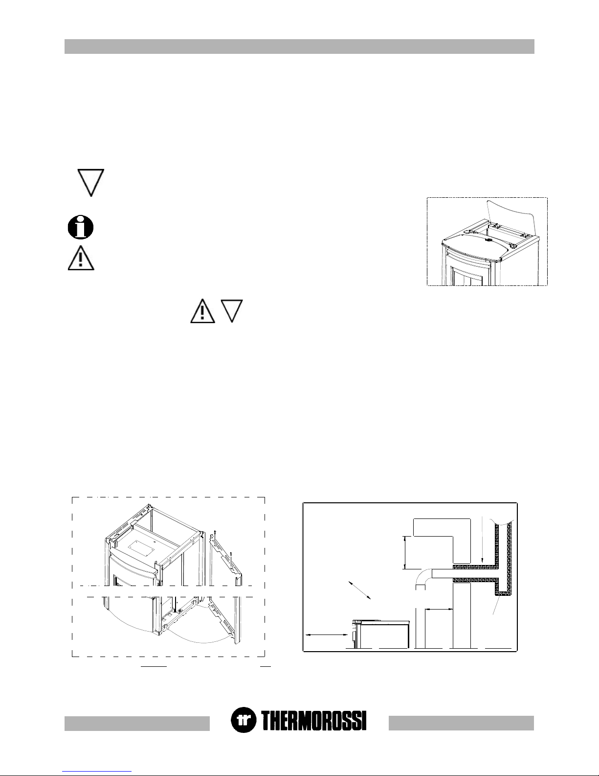
CAUTION : Always use trolleys to move the appliance and the appliance must always be in a vertical position. Follow the general guidelines set
out in paragraph 1.1 to the letter. Keep in mind that the flooring of the room in which the heater is to be installed must withstand the combined
weight of the appliance and the pellets contained in the tank.
CAUTION: The room in which the appliance will operate must be adequately ventilated (minimum air intake 1300 m3/h).
The appliance must be positioned at a minimum safe distance from walls and furnishings. This distance will have to be increased considerably
if the objects surrounding the appliance are inflammable (matchboarding, furniture, curtains, picture frames, sofas, etc...).
The recommended minimum distances are illustrated in the drawing below on the right. Installation in the vicinity of heat-sensitive materials is only
permitted if suitable insulating protection is placed between the object and the appliance (ref. Uni 10683). Adjust the mounting feet to obtain a
slight gap between heater and flooring to ensure that the heater is not resting directly on the floor. It is advisable to interpose a floor protector
plate between the heater and the floor if the latter is made of wood or other combustible material.
4.1.14.1.1
4.1.14.1.1
4.1.1
MOUNTING MET MOUNTING MET
MOUNTING MET MOUNTING MET
MOUNTING MET
ALAL
ALAL
AL
COLCOL
COLCOL
COL
OR CASINGOR CASING
OR CASINGOR CASING
OR CASING
Once the heater has been positioned the next step is to install the side panels and the top ceramic panel as shown in the image below on the
left.The mounting sequence is as follows:
- Remove the top cast iron cover
- Insert the side panel position the bottom holes on the folds in the base and fix the 2 top screws (Figure 1A).
- Then mount the top cover and the ceramic panel.
Remember that the heater must be completely cooled down before the side panel can be cleaned with a soft cloth and water.
The casing on the Easy model is factory-mounted before delivery .
Figura 1 A
Figura 1A
3.33.3
3.33.3
3.3
THE FEEDBOTHE FEEDBO
THE FEEDBOTHE FEEDBO
THE FEEDBO
XX
XX
X
The feedbox is situated in the top part of the heater. The maximum load capacity of the tank is
approximately 16 Kg, but varies according to the specific weight of the pellets. The manufacturer
recommends emptying the hopper and vacuuming the screw feeder zone once a
month and during the summer period. Take special care when loading the hopper as
the screw feeder at its base is in motion.
450 mm SE MATERIALE COMBUSTIBILE
450 mm SE MATERIALE COMBUSTIBILE
ISOLANTE TERMICO
2
0
0
m
m
S
E
M
A
T
E
R
I
A
L
E
C
O
M
B
U
S
T
I
B
I
L
E
200 mm SE MATERIALE
COMBUSTIBILE
Tee ispezionabile
KEY
Heat insulating material
Inspectable Tee element
200/450 mm if the material is combustible
Figure / Detail
LEGENDA
Isolante termico
T ispezionabile
200/450 mm se materiale combustibile
Figura / Dettaglio
Page 7
pg. 7
Figura 4
Figura 3
Figura 1
A
DETTAGLIO A
Figura 2
A
B
C
D
F
E
G
H
SID
SSD
4.1.24.1.2
4.1.24.1.2
4.1.2
MOUNTING CERAMIC CASING MOUNTING CERAMIC CASING
MOUNTING CERAMIC CASING MOUNTING CERAMIC CASING
MOUNTING CERAMIC CASING
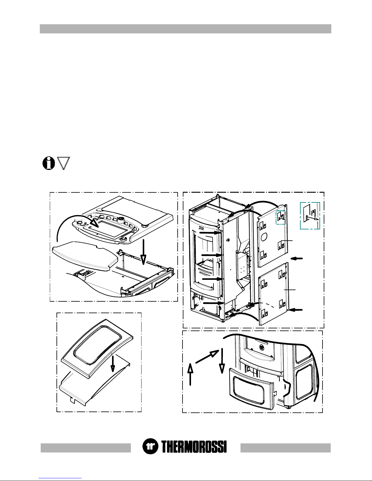
The next step, after positioning the heater, is to mount the ceramic casing as illustrated in the figures below.
Carry out the following operations:
- Remove the top cast iron cover ( Figure 1).
- Mount the right ceramic panel supports (figure 2) following the procedure set out below:
Undo screws A and B and remove them momentarily. Fix support SID by firstly inserting the bottom folds on the seat of the heater base, next
re-insert and fasten screws A and B. Undo screws C and B and remove them momentarily. Fix support SSD then re-insert and fasten screws
C and D. Next screw in screws E and F provided. Screw in screws G and H provided. If the holes for the screws are not already present drill
holes using a d.3.5 bit.Bend the tabs slightly (indicated in detail A of Figure 2) outwards from the heater. Next fix the side ceramics to the supports
by securing them to the bent tabs. Next mount the left ceramic panel supports using the same procedure as described above for the right
ceramic panel supports (Figure 2).
Next attach the side ceramic panels to the supports.
- Fix the lower front ceramic panel to its support (Figure 3) with the silicone provided; degrease and clean the ceramic panel support before
gluing the parts to ensure optimal adhesion. Leave the ceramic panel in the position illustrated in Figure 3 and wait 24 hours before handling it.
- Next fasten the lower ceramic panel to the heater following the instructions set out in Figure 4.
- Lastly position ceramic top ( Figure 1).
Special care must be taken when handling and mounting the ceramics in order to prevent breakages that are not covered by
warranty.
Small imperfections on the surfaces of the ceramics such as: dimples, shivering and slight colour variations are normal
characteristics of handcrafted ceramics which make each piece unique.
Page 8
pg. 8
55
55
5
DESCRIPTION OF ECOTHERM 3001 CONTROLSDESCRIPTION OF ECOTHERM 3001 CONTROLS
DESCRIPTION OF ECOTHERM 3001 CONTROLSDESCRIPTION OF ECOTHERM 3001 CONTROLS
DESCRIPTION OF ECOTHERM 3001 CONTROLS
5.15.1
5.15.1
5.1
DESCRIPTION OF GREY HANDHELD RADIO CONTRDESCRIPTION OF GREY HANDHELD RADIO CONTR
DESCRIPTION OF GREY HANDHELD RADIO CONTRDESCRIPTION OF GREY HANDHELD RADIO CONTR
DESCRIPTION OF GREY HANDHELD RADIO CONTR
OL OL
OL OL
OL
AND HEAAND HEA
AND HEAAND HEA
AND HEA
TER REAR PTER REAR P
TER REAR PTER REAR P
TER REAR P
ANELANEL
ANELANEL
ANEL
INTRODUCTION
The handheld radio control is the control instrument for your heater that will permit you to manage Ecotherm and its functions. The radio
control is a user-friendly way of interacting with the main heater settings and, when required, of accessing the various other control
commands. In both cases the Manufacturer recommends you read the following pages carefully so that you will know how to make the best
use of your heater. Keep in mind that radio wave transmissions can be affected by the surrounding environment: the presence of thick walls
can reduce the transmission that normally extends to 6-7 metres.
CAUTION: to guarantee optimal data transmission it is advisable to always place the radio control in its support in a vertical
position.
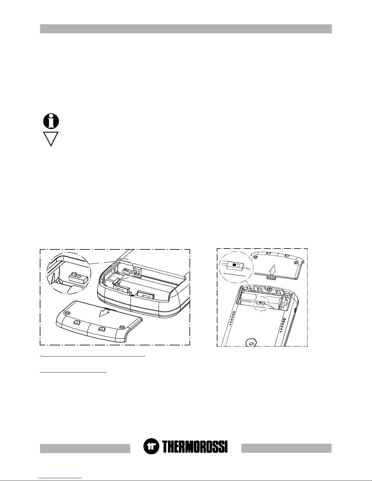
The following operations must be carried out the first time the heater is started up :
- Turn the switch inside the battery compartment to ON (see drawing below)
- Connect the radio control by means of the battery charger supplied to the power line, ( it must be recharged for
at least 5 days: see para. 8.3), as the rechargeable batteries could be partially or completely flat). Leave the radio
control connected at all times, by means of the battery charger, to the power supply line. The heater must be
energised and the switch turned to position "1". At the end of the winter season it is mandatory to switch off the
radio control completely, by means of the switch situated inside the battery compartment, in order to preserve
the life of the batteries. The batteries are guaranteed for 6 months. When the batteries are exhausted dispose of
them safely. It is normal for the temperature sensor to detect temperatures which are slightly different to the
real ones: variations caused by the environment in which the radio control is positioned.
(1) Insert on/off and flame adjustment button When you press this button the appliance (10) switches to ON/ RUNNING/ OFF. Press
repeatedly to activate up to 5 bars (7) and the AUTO indicator is activated (8 automatic) .
(2) Ventilation setting button Press this button to set the desired level of ventilation: up to a maximum of 6 speeds are available, indicated by
the lighting of the corresponding bar (6).
5.1.2 ROOM TEMPERATURE THERMOSTAT OPERATION
When the AUTO function is activated the temperature value detected by the temperature sensor (5) installed in the radio control is updated at
regular intervals.During the start up phase the temperature value is not updated. The temperature value transmitted to the heater does not change
the instant there is a sudden change in the room temperature but it is updated regularly through the DATA ANALYSIS function. It is normal for the
temperature sensor to detect temperatures which are slightly different to the real ones: these variations are caused by the environment in which
the radio control is positioned and by the prolonged use of the display.
O
n
O
n
O
n
O
n
1
22
O
N
O
N
O
N
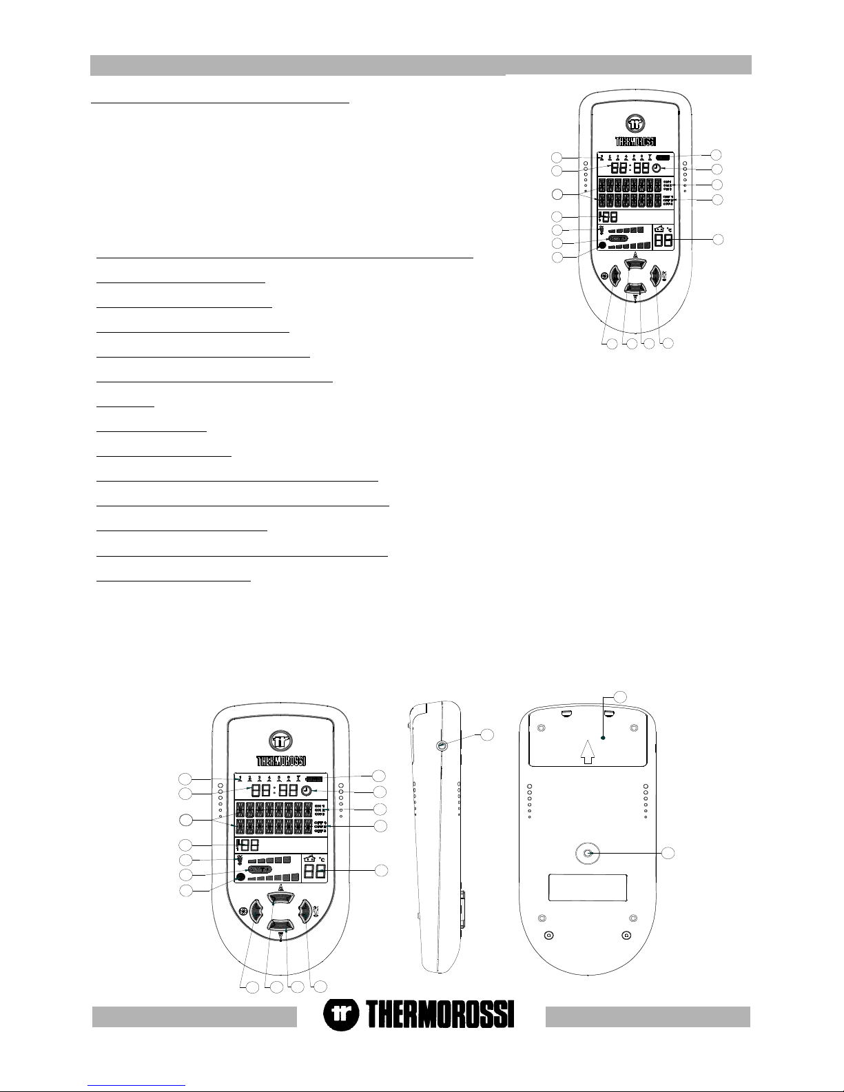
5.1.1 HANDHELD RADIO CONTROL
A description of the buttons and indicators on the radio control follows:
The radio control consists of a plastic shell on which is installed a backlit LCD display with control buttons, interface card and
rechargeable batteries: the backlighting switches off temporarily during use in order to reduce energy consumption which consequently
extends the duration of the charge. There are two main control pushbuttons marked with the ventilation symbol (2) and the symbol of
the flame (1). The flame button (1) sets the heater power, there are a possible 5 power levels displayed by the 5 bars progressively
coming on in sequence (7). You can select the AUTOMATIC mode displayed by the text word AUTO (see paragraph 5.9 ). The shutdown
cycle appears on the display when all the power bars are off. The fan button (2) controls the ventilation of the heater. The heater
activates when the temperature exceeds 42 °C. The ventilation can be set up to 6 speed levels: when the heater is on the ventilation
cannot be switched off.
Therefore, in brief, the two buttons function as follows:
Page 9
pg. 9
18
1
2
3
4
5
6
7
8
9
10
11
12
13
14
15
16
17
19
1
2
3
4
5
6
7
8
9
10
11
12
13
16
15
14
(3) (4) Auxiliary buttons for temperature setting
Press button 3 to lower the temperature. Press button 4 to raise the temperature level set in
Aladino. As is explained below they are only functional if the AUTO cycle is selected. The set
temperature appears in zone 9 of the display.
The room temperature, however, appears in zone 5 of the display. In this operating cycle the
ventilation and power self-regulate according to the set temperature and the temperature
detected in the display. It is not possible to set the air flow discharging from the heater at any
desired temperature because it is autonomously established by the heater according to the
ambient temperature. If the AUTO function is not activated the temperature value set with buttons
3 and 4 is ignored.
5.1.35.1.3
5.1.35.1.3
5.1.3
Indicators of the handheld radio controlIndicators of the handheld radio control
Indicators of the handheld radio controlIndicators of the handheld radio control
Indicators of the handheld radio control
(5) "Room temperature detected by the radio control's sensor indicator
(6) "Ventilation level" indicator
(7) “Combustion level” indicator
(8) "AUTO" CYCLE ACTIVE indicator
(9) “Room temperature setting" indicator : this is the room temperature that you wish to reach by means of buttons 3 and 4.
(10) Display zone where the following appear: operating phases, programming, MENU …
(11) Clock
(12) Day of the week
(13) Battery charge level
(14) “Chronothermostat enabled-disabled” indicator
(15) (16) On-off indicators for the programming phase
(17) Battery charger connection
(18) “Code selector” and “Battery compartment” cover
(19) “MENU” selection button To access the main menu press the button marked 19. Press button 19 repeatedly to scroll the
adjustment, setting and programming windows (see para. 5.2 , 5.3 , 5.4 , 5.5 , 5.6 , 5.7) . This button can also carry out DATA
ANALYSIS functions: fundamental control function for updating data.
After having carried out the DATA ANALYSIS all the data will be updated: it is normal for the temperature sensor to detect temperatures
which are slightly different to the real ones: variations caused by the environment in which the radio control is positioned.
To exit the main menu without having to scroll all the possible adjustments/ functions, simply press button (1) to return to the heater
operating status.
Page 10
pg. 10
28
27
26
21
25
29
23
24
22
20
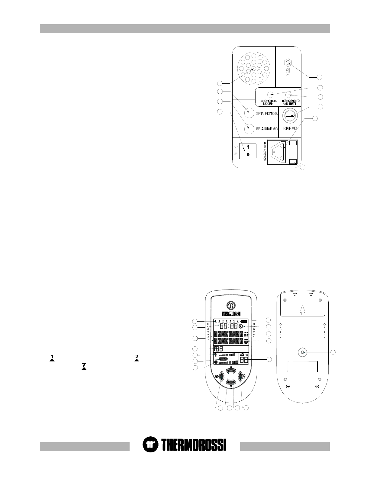
5.1.4 HEA5.1.4 HEA
5.1.4 HEA5.1.4 HEA
5.1.4 HEA
TER REAR PTER REAR P
TER REAR PTER REAR P
TER REAR P
ANELANEL
ANELANEL
ANEL
The rear panel integrates the radio control.
A description of the functions of the buttons and LEDs on the rear panel of the
heater:
(20) Insert on/off and flame adjustment button
By pressing this button you can use the heater even without the radio control.
Press button (20) repeatedly to increase the combustion power, whereas the
ventilation level is adjusted automatically according to the selected combustion
power. One or more acoustic signals correspond to each power step
selected:
-1 power bar -- 1 acoustic signal
-2 power bars -- 2 acoustic signals
-........................................................................
-5 power bars -- 5 acoustic signals
If you press once again the acoustic signals will not sound: this means that
after 5 seconds the heater will set itself in OFF mode and consequently shut
down. It is not possible to select the AUTO cycle.
21 Loudspeaker for voice alarms/information: the heater gives
information on its status and any active alarms through this loudspeaker.
22 Power outlet for additional room temperature connection.(see
para. 7.1)
(additional room temperature thermostat not supplied)
23 Power outlet for additional chronothermostat connection.(see
para. 7.2)
(additional chronothermostat not supplied)
24 Overtemperature thermostat button cap
In the event of overtemperature this safety thermostat stops the loading of pellets. When it is activated LED 27 comes on. To restart the
heater you need to wait until it cools down, then verify the cause for the overheating, remove the cause, unscrew the protective cap and
press the button (24) .
25 Electrical power outlet 220-240V 50Hz
26 Loading motor test LED.
The light must come on when the pellet screw feeder starts .
27 Reset thermostat tripped indicator light. This LED comes on when the reset thermostat is activated.
28 Main switch 0-1
29 General fuse 3.15 A
19
3
4
2
1
10
9
8
7
6
12
11
16
5
15
14
13
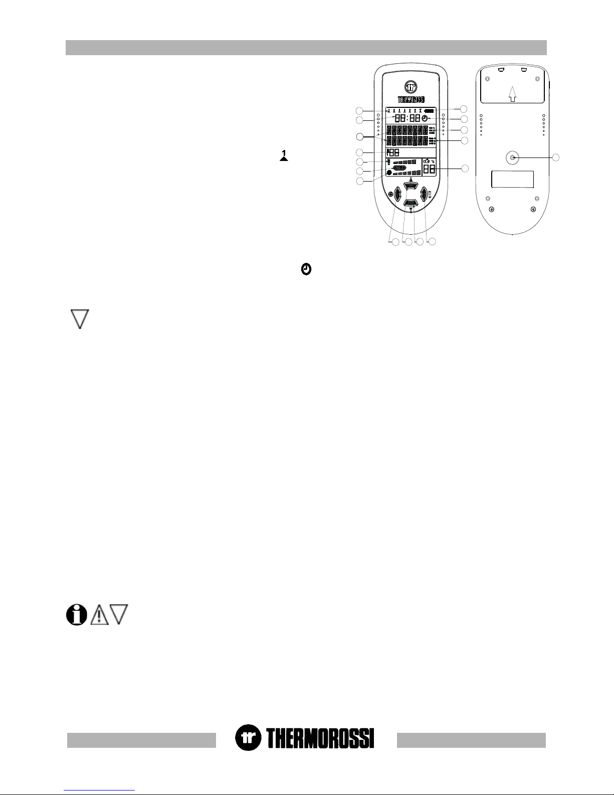
5.2 D5.2 D
5.2 D5.2 D
5.2 D
AA
AA
A
Y Y
Y Y
Y
AND AND
AND AND
AND
TIME SETTINGTIME SETTING
TIME SETTINGTIME SETTING
TIME SETTING
The heater must be energised and the switch at the back turned to
position "1"(see image in top right corner).
To set the clock and the day of the week carry out the procedures
described below. Press the button (19) on the back of the radio
control repeatedly until the word TIME appears.
To set the day press the button (2) . The word DAYS will appear on
the display, and the indicator (12) will start to blink. Press the button
(3) and/or (4) to set the number that corresponds to the current day.
The symbol corresponds to Monday , the symbol to Tuesday
..... and the symbol to Sunday. To confirm the selection press the
button (1). Next the word HOUR will appear on the display, and the
hour indicator (11) will start to blink. Press button (3) and/or (4) to set
the current time. To confirm the selection press the button (1). Next
the word MINUTES will appear on the display and the minute
indicator (11) will start to blink. Press buttons (3) and/or (4) to set the
current minutes . To confirm the selection press the button (1). The
day and time setting is now completed : at this point the heater
operating status will appear on the display.
KEY
Room temperature thermostat
Chronothermostat - modem
Motor LED
Reset LED
Reset
LEGENDA
Termostato ambiente
Cronotermostato - modem
Spia Motor
Spia riarmo
Riarmo
Page 11
pg. 11
19
3
4
2
1
10
9
8
7
6
12
11
16
5
15
14
13
5.3 ON/OFF PROGRAMMING.5.3 ON/OFF PROGRAMMING.
5.3 ON/OFF PROGRAMMING.5.3 ON/OFF PROGRAMMING.
5.3 ON/OFF PROGRAMMING.
The heater must be energised and the switch at the back in position "1".
The weekly programming can be executed with the help of the handheld radio
control. It is possible to set up to 3 on-off cycles for each day from Monday to
Sunday. To access the programming mode press the button (19) on the back of
the radio control repeatedly until the word CRONO appears.
Press button (3) or (4) to enable/disable the program setting ( symbol (14)
present / absent): this function is useful if you wish to disable the established
weekly program setting. To program the heater you need to access the
chronothermostat function by pressing the button (2): the LED (12) comes on
(this indicates that Monday, the first day of the week, is being programmed). The
text ON1 of the indicator (15) comes on and the word HOURS appears on the
display. Press button (3) and/or (4) to enter the hour of the first cycle start time.
To confirm the selection press the button (1). The word MINUTES will appear on
the display. Press button (3) and/or (4) to enter the minutes of the first cycle
start time. To confirm the selection press the button (1). Next the text OFF1
(indicator (16) will appear on the display. Proceed using buttons (3), (4) and (1)
as indicated above to set HOURS and MINUTES for the cycle end time. At this
point the first on-off cycle for Monday has been entered. It is then possible to set
the second on-off cycle for Monday (indicated by the texts ON2 and OFF2) and
the third on-off cycle for Monday (indicated by the texts ON3 and OFF3) . Now program the on-off cycles for the remaining days of the week
up to and including Sunday. When the programming mode is active ( symbol present) the minimum operating value at cycle on
(combustion power - ventilation speed ) is the same minimum operating value that was set before the last cycle off.
If the second on-off cycle is not required simply set the ON2 time as 00:00 and the OFF2 time as 00:00 .
In the event of a programmed cycle on always ensure that the brazier is clean and seated correctly in its lodging: failure to keep the
brazier clean can reduce the life of the spark plug.
5.4 5.4
5.4 5.4
5.4
VV
VV
V
OICE INFORMAOICE INFORMA
OICE INFORMAOICE INFORMA
OICE INFORMA
TION TION
TION TION
TION
VV
VV
V
OLOL
OLOL
OL
UME CONTRUME CONTR
UME CONTRUME CONTR
UME CONTR
OLOL
OLOL
OL
The heater must be energised and the switch at the back turned to position "1".
Your heater informs you on its operating status and on any problems that could arise by means of voice messages . Select the volume level
for the voice messages by carrying out the following procedure. When the insert is in the POWER OFF, POWER ON or RUNNING status
simply press the button (19) until the word VOLUME appears on the display (10). Press button (2) and the word SELECT appears on the
display: the introductory music plays. Press button (4) repeatedly and the + symbol appears (to increase the volume) .
Press button (3) repeatedly and the - symbol appears (to lower the volume). To confirm the volume selection press the button (1). The heater
then returns to its previous POWER ON or RUNNING or POWER OFF status.
5.5 OPERA5.5 OPERA
5.5 OPERA5.5 OPERA
5.5 OPERA
TING LEVEL SETTINGTING LEVEL SETTING
TING LEVEL SETTINGTING LEVEL SETTING
TING LEVEL SETTING
The heater must be energised and the switch at the back turned to position "1".
Your appliance is delivered with an excellent program installed that favours combustion yield; the program is called Level 1.
If you are using pellets with a higher than normal incidence of residues after combustion in the brazier, alternative levels may be selected:
Level 2 : this program increases the smoke suction unit speed acceleration.
Level 3 : this program increases the suction unit speed to a greater degree than level 2.
Level 0 : when using lightly-compressed pellets and/or flue outlets with very high vacuum, over 2 mm water column.
The pellet consumption value is not affected by the operating level settings.
Select the required level by acting as follows:
Press the (19) button on the back of the radio control repeatedly until the text indicating the preset heater level appears on the display (Level
1 or Level 2 or Level 3 or Level 0). Press the button (2) and the word SELECT appears on the display (10). To change the operating level
hold down button (3) and press button (4).
By holding down button (3) and pressing button (4) repeatedly the level changes in the following sequence: Level 2... Level 3...Level
0...Level 1.., next press button (1) to confirm the selected level.
The level selection can be made with the heater OFF or ON. If the change is made while the insert is running the
difference in the flame will be apparent. It is mandatory to pay particular care when selecting the most appropriate
operating cycle for your installation. After the selection of the operating cycle a thorough cleaning of the brazier is
mandatory.
5.6 LANGUAGE SELECTION5.6 LANGUAGE SELECTION
5.6 LANGUAGE SELECTION5.6 LANGUAGE SELECTION
5.6 LANGUAGE SELECTION
The heater must be energised and the switch at the back turned to position "1".
Press the MENU' button (19) repeatedly until the word ITALIAN appears on the display (10) . To change the display language proceed as
follows: Press button (2) and the SELECT ITALIAN text appears on the display. Press button (4) repeatedly to select German, English,
French. Once you have selected the desired language press button (1) : the radio control carries out a data analysis, that is, an update of
the new language.
Page 12

pg. 12
5.7 D5.7 D
5.7 D5.7 D
5.7 D
AA
AA
A
TT
TT
T
A A
A A
A
ANAN
ANAN
AN
ALAL
ALAL
AL
YY
YY
Y
SISSIS
SISSIS
SIS
DATA ANALYSIS represents the function concerning update of data between the heater and the handheld radio control. The radio wave
transmission is frequently used by numerous applications: the DATA ANALYSIS function is used to update the temperature, ventilation,
power, temperature analysis, system status. The DATA ANALYSIS process can take from a minimum of 18 seconds to a maximum of 40
seconds. If the DATA ANALYSIS is not executed successfully, repeat the operation by pressing the button (19) for a few seconds then
releasing it.
5.8 TRANSMISSION - RECEPTION ALARMS5.8 TRANSMISSION - RECEPTION ALARMS
5.8 TRANSMISSION - RECEPTION ALARMS5.8 TRANSMISSION - RECEPTION ALARMS
5.8 TRANSMISSION - RECEPTION ALARMS
If a problem arises with the communication between the handheld radio control and the heater the following messages could appear on the
display:
OUT OF RANGE : the radio control is located at a distance that is greater than the radio control's radius of action.
NO CURRENT : the heater has shut down and does not appear to be powered by electricity.
PRESS A BUTTON : if the radius of action has been exceeded, to restore communication with the heater press one of the
buttons on the radio control for approx. 2 seconds.
AVVIO
5.9 5.9
5.9 5.9
5.9
AA
AA
A
UTUT
UTUT
UT
OMAOMA
OMAOMA
OMA
TIC / MANUTIC / MANU
TIC / MANUTIC / MANU
TIC / MANU
AL OPERAAL OPERA
AL OPERAAL OPERA
AL OPERA
TING MODETING MODE
TING MODETING MODE
TING MODE
5.9.1 DESCRIPTION OF 5.9.1 DESCRIPTION OF
5.9.1 DESCRIPTION OF 5.9.1 DESCRIPTION OF
5.9.1 DESCRIPTION OF
THE THE
THE THE
THE
AA
AA
A
UTUT
UTUT
UT
OMAOMA
OMAOMA
OMA
TIC OPERATIC OPERA
TIC OPERATIC OPERA
TIC OPERA
TING MODE CYTING MODE CY
TING MODE CYTING MODE CY
TING MODE CY
CLECLE
CLECLE
CLE
In the automatic operating cycle the heater expresses its maximum flexibility of operation
while optimising fuel consumption. During the AUTO cycle the heater self-regulates the
combustion and ventilation according to the temperature (9) set by means of buttons (3) and
(4). If for example the temperature (9) is set at 23°C the heater attempts to take the room
temperature (5) detected by the handheld radio control to 23°C in the shortest possible time
by modulating power and ventilation as the room temperature approaches set temperature
(9). Once this temperature is reached the heater settles at the minimum operating value for
combustion and ventilation. To select this function press the button (1) repeatedly until the
word AUTO appears on the display (see image on the right). During the POWER ON phase,
that takes 20 minutes, the heater ignores all the commands transmitted. After this time has
elapsed the word POWER ON disappears on the delay and the word RUNNING appears :
during this phase the AUTOMATIC cycle is operational. The room fan starts operating as
soon as the heater body exceeds the 42°C threshold.
It is normal for the temperature sensor to detect temperatures which are slightly
different to the real ones: variations caused by the environment in which the radio control is positioned.
5.9.2 DESCRIPTION OF 5.9.2 DESCRIPTION OF
5.9.2 DESCRIPTION OF 5.9.2 DESCRIPTION OF
5.9.2 DESCRIPTION OF
THE MANUTHE MANU
THE MANUTHE MANU
THE MANU
AL OPERAAL OPERA
AL OPERAAL OPERA
AL OPERA
TING MODE CYTING MODE CY
TING MODE CYTING MODE CY
TING MODE CY
CLECLE
CLECLE
CLE
The manual cycle is indicated by the absence of the word AUTO on the display. The
combustion and ventilation power can be controlled independently from each other by means
of the buttons (1) and (2). During the POWER ON phase, that takes 20 minutes, the heater
ignores all the commands transmitted to it. After this time has elapsed the word POWER ON
disappears on the delay and the word RUNNING appears : during this phase the MANUAL
cycle is operational. The room fan starts operating as soon as the heater body exceeds the
42°C threshold. The combustion is regulated by 5 bars, the regulation of the ventilation is
distributed on 6 steps. The room temperature thermostat is disabled when this function is
operational. It is normal that in the manual cycle the ventilation is often set at the maximum
speed in order to cool the heater body more effectively.
AVVIO
Page 13

pg. 13
SELETTORE CODICI PER RADIOCOMANDO
PALMARE GESTITO VIA ONDE RADIO
O
N
1
2
O
N
1
2
ON
2
1
2
1
3
4
5
6
PER RADIOCOMANDO
1
2
ON
SELETTORE CODICI
5.10 TRANSMISSION CODES SETTING5.10 TRANSMISSION CODES SETTING
5.10 TRANSMISSION CODES SETTING5.10 TRANSMISSION CODES SETTING
5.10 TRANSMISSION CODES SETTING
Before beginning any maintenance operation ensure that the appliance is in the OFF phase and disconnect it from the electric power outlet.
When several heaters are located in rooms that are very close to each other or if there are other radio frequency controlled appliances in
close vicinity it may be necessary to set different transmission codes. The change of code must be made both on the motherboard inserted
in the heater (see figure below left ), and in the radio control (see figure below left). Position the switch 0-1 (located on the back of the
heater) on 0. To access the board you need to remove the heater's right side panel as described in para. 4.1.1 and remove the board cover
by undoing the two screws as indicated in the figure below on the right.
The codes must be identical, and for this purpose you could use the numbers marked on the microswitches as reference. Firstly set the new
code on the mother board, then set the new code on the radio control then execute a forced DATA UPDATE by repeatedly pressing button
(19) located on the back of the radio control until the words DATA ANALYSIS appear: once the text appears hold down the button (19) for 5
seconds then release it. This procedure executes a complete resetting of the transmission codes.
5.11 CARE AND MAINTENANCE OF THE RADIO CONTROL5.11 CARE AND MAINTENANCE OF THE RADIO CONTROL
5.11 CARE AND MAINTENANCE OF THE RADIO CONTROL5.11 CARE AND MAINTENANCE OF THE RADIO CONTROL
5.11 CARE AND MAINTENANCE OF THE RADIO CONTROL
The radio control has been designed and produced to the strictest standards and must be handled with great care.
If you observe the guidelines set out below, the radio control will provide a long trouble-free performance:
-Protect the radio control against humidity! Precipitation, humidity and liquids corrode the electronic circuits. If the radio control is wet,
disconnect it immediately from a power source, remove the battery, open it and allow it to dry at room temperature.
-Do not use or store the radio control in dusty or dirty environments. The dust/dirt could damage the movable parts of the radio control.
-Do not store the radio control in very hot environments. High temperatures could shorten the life of the electronic devices, damage the
batteries and deform or even melt plastic parts. -Do not store the radio control in cold environments. When it heats up (when it returns to
normal operating temperature), humidity could form inside it and damage the electronic circuits.
-Do not drop the radio control, do not hit or bump it and do not shake it. Actions such as these could damage the internal circuits of the
device.
-Do not use corrosive chemical substances, caustic solutions or detergents to clean the radio control.
All the above guidelines apply equally to the radio control, the battery, the battery charger, and all the accessories.
The parts subject to wear (such as batteries, keypads, lodging compartments, small compartment parts) are guaranteed for 6 months from
the purchase date. The guarantee does not apply if the defect is caused by non-conforming use and/or if the instructions and guidelines
described above are not observed to the letter. Non-conformities must be reported within two months of having identified them. Devices or
parts returned for replacement become the property of Thermorossi.
The presence of irregular black-blue lines on the display (also present when de-energised and battery flat or missing) indicate that
the glass screen of the display is damaged following a fall or impact: in this case the breakage is not covered by the guarantee.
KEY
Radio control code selector
Radio wave-controlled code selector for handheld
radio control
LEGENDA
Selettore codici per radiocomando
Selettore codici per radiocomando palmare gestito
viaonde radio
Page 14

pg. 14
5A5A
5A5A
5A
DESCRIPTION OF "ECOTHERM 3001 THERMOCOMFORT" CONTROLSDESCRIPTION OF "ECOTHERM 3001 THERMOCOMFORT" CONTROLS
DESCRIPTION OF "ECOTHERM 3001 THERMOCOMFORT" CONTROLSDESCRIPTION OF "ECOTHERM 3001 THERMOCOMFORT" CONTROLS
DESCRIPTION OF "ECOTHERM 3001 THERMOCOMFORT" CONTROLS
5A.15A.1
5A.15A.1
5A.1
DESCRIPTION OF CONTRDESCRIPTION OF CONTR
DESCRIPTION OF CONTRDESCRIPTION OF CONTR
DESCRIPTION OF CONTR
OL POL P
OL POL P
OL P
ANEL ANEL
ANEL ANEL
ANEL
AND HEAAND HEA
AND HEAAND HEA
AND HEA
TER REAR PTER REAR P
TER REAR PTER REAR P
TER REAR P
ANELANEL
ANELANEL
ANEL
5A.1.1 DESCRIPTION OF CONTROL PANEL
There are two main control pushbuttons marked with the ventilation symbol (2) and the symbol of the flame (1).The flame pushbutton (1)
sets the power of the heater with 5 levels available which are activated as the 5 leds light up in sequence (10). The off cycle is activated
when all power leds are turned off. Key (2) controls the ventilation of the heater. The heater activates when the temperature exceeds 42
°C. The ventilation can be set up to 6 speed levels (9): when the heater is on the ventilation cannot be switched off .
5A.1.2 REAR PANEL
A description of the functions of the buttons and LEDs on the back panel of
the heater:
(11) Main switch 0-1
(12) Heater electrical power outlet 220-240V 50 Hz.
(13) Overtemperature thermostat button cap
In the event of overtemperature this safety thermostat stops the loading of
pellets. When it is activated LED 15 comes on.
To restart the heater you need to wait until it cools down, then verify the
cause for the overheating, remove the cause, unscrew the protective cap
and press the button (13) .
(14) Feed motor test indicator light When the pellet screw feeder is set
in motion the light must come on.
(15) Reset thermostat tripped indicator light. This LED comes on when
the reset thermostat is activated.
(16) Power outlet for additional chronothermostat connection
(additional chronothermostat not supplied)
(17) Power outlet for additional room temperature thermostat
connection
(additional room temperature thermostat not supplied)
All controls and indicators are presented here below :
(1) Insert on/off and flame adjustment button When you press this button the appliance (10) switches to Start / ON / OFF. Up to 5
leds (10) are activated when pressed repeatedly.
(2) Ventilation setting button Press this button to set the desired level of ventilation: up to a maximum of 6 speeds are available,
indicated by the lighting of the corresponding leds (9).
(3) (4) Auxiliary setting keys Keys (3) and (4) are operating keys necessary when on-off cycles are programmed, for operative levels,
clock setting, etc..
5) Programming Enable / Disable keys
(6) “MENU” selection button To access the main menu press the button marked with 6. Press button 6 repeatedly to scroll the
adjustment, setting and programming windows.
(7) Display
(8) Infrared sensor for remote control
(9) Ventilation level leds
(10) Combustion level leds
1
2
3
4
5
6
7
8
9
10
11
13
14
15
16
17
12
KEY
Room temperature
thermostat
Chronothermostat
- modem
Motor LED
Reset LED
Reset
LEGENDA
Termostato
ambiente
Cronotermostato -
modem
Spia Motor
Spia riarmo
Riarmo
Page 15

pg. 15
5A.2 D5A.2 D
5A.2 D5A.2 D
5A.2 D
AA
AA
A
Y Y
Y Y
Y
AND AND
AND AND
AND
TIME SETTINGTIME SETTING
TIME SETTINGTIME SETTING
TIME SETTING
The heater must be fed with the rear switch in position "1". Display (7) may show the inscriptions On , OFF or Start. ".
To set the time and the day of the week carry out the
procedures described below. Press once the key (6), and the
inscription HoUr will flash. After a few seconds the fixed
inscription days will appear. In order to add just the day,
repeatedly press key (4) and/or (3) until the led turns on in
area (9) which corresponds to the present day; Monday is
indicated by the 1st led on, Tuesday is indicated by the 2nd
led on,....... Saturday is indicated by led (6) on, while Sunday
corresponds to all 8 leds being on. Then confirm the day by
pressing the key (1). The 2 digits representing the hours will start flashing in the display: it is possible to select the present hour using the
arrow keys (4) and/or (3); the selection must be confirmed by pressing key (1). The 2 digits indicating the minutes will start flashing: it is
possible to select the present minutes using the arrow keys (4) and/or (3), the selection must be confirmed by pressing the key (1). The
setting of the day and of the hour is now completed. For the entire procedure to be confirmed and to move back to the heater status display,
key (6) must be repeatedly pressed until the operating status is displayed: On, Off, or Start. :
5A.3 ON / OFF PROGRAMMING5A.3 ON / OFF PROGRAMMING
5A.3 ON / OFF PROGRAMMING5A.3 ON / OFF PROGRAMMING
5A.3 ON / OFF PROGRAMMING
The heater must be fed with the rear switch in position "1". Display (7) may show the inscriptions On , OFF or Start..
It is possible to carry out the weekly programming by setting
up to 3 on/off cycles for each day from Monday to Sunday.
To carry out the programming, push button (6) must be
pressed twice until the inscription cr on is on.: in area (9) a
led goes on (which indicates that the first day of the week,
Monday, is being programmed). Inscription On1 will appear
on the display, and the 2 digits representing the hours will
turn on. Press button (3) and/or (4) to enter the hour of the
first cycle start time. To confirm the selection press the
button (1). The two digits representing the minutes will be turn on. Press button (3) and/or (4) to enter the minutes of the first cycle start
time. For the selection to be confirmed press the key (1). The first hour for the Monday on-cycle has been set. Then the inscription OFF1 will
appear in the display and the two digits representing the hours will turn on. When the (3) and/or (4) is pressed the hour of the first off-cycle
is entered. To confirm the selection press the button (1). The two digits representing the minutes will be turn on. By pressing the key (3) and/
or (4) the minutes for the first off-cycle will be entered To confirm the selection press the button (1). At this point the first on-off cycle for
Monday has been entered. Later, it is possible to set the Monday’s second on-off cycle (shown with the display of On2 and OFF2) and the
third Monday’s on-off cycle (shown with the display On3 and OFF3) . Inside the programming menu, if for example the Wednesday’s
programming is to be changed, go to the third green led by pressing key(2): then it is possible to change the on-off programs for Wednesday,
confirm the change by pressing the key (6). If the second on-off cycle is not required simply set the ON2 time as 00:00 and the OFF2 time as
00:00 .
The programming procedure ends when you confirm the last data entered by pressing button (6) or when you exiting the programming menu.
Pressing pushbutton (5) programming is enabled/disabled (Enabled= message on cr temporarily displayed and, at the same time, a fixed
point is present on the right side at the bottom of the display. Disabled= message of cr temporarily displayed and, at the same time, the point
on the right side at the bottom of the display is not present.) : this function is useful if one wants to prevent the weekly established
programming. With the programming active, the operating conditions at the start-up (combustion power – ventilation speed) are the same as
set-up before the last off-cycle of the heater: this is the case if the off-cycle has been done through the programming and not through a
manual action. In case the off-cycle (if carried out while the heater cycle is being controlled by the programming) is activated manually, at the
next start up controlled by the programming the heater will be set at the 1st combustion power level and the 1st ventilation speed.
In order to display the present time and programmings, key (6) must be repeatedly pressed until the current time is displayed. By pressing
keys (3) and/or (4) all programming values will be displayed : to exit this condition, twice press the key (6) .
In the event of a programmed cycle
on always ensure that the brazier is
clean and seated correctly in its
lodging: failure to keep the brazier
clean can reduce the life of the spark
plug.
1
2
3
4
5
6
7
8
9
10
1
2
3
4
5
6
7
8
9
10
Esempio di come si presenta il display
con la programmazione attivata.
Esempio di come si presenta il display
con la programmazione disattivata.
On
Presenza fissa punto
On
Assenza punto
KEY
Point steady presence
Point absence
Example of how the display
appears with the
programming activated/
deactivated.
LEGENDA
Presenza fissa punto
Assenza punto
Esempio di come si
presenta il display con la
programmazione attivata /
disattivata
Page 16

pg. 16
66
66
6
USE OF USE OF
USE OF USE OF
USE OF
THE "ECOTHE "ECO
THE "ECOTHE "ECO
THE "ECO
THERM 3001" HEATHERM 3001" HEA
THERM 3001" HEATHERM 3001" HEA
THERM 3001" HEA
TERTER
TERTER
TER
6.16.1
6.16.1
6.1
5.15.1
5.15.1
5.1
SWITSWIT
SWITSWIT
SWIT
CHING ON CHING ON
CHING ON CHING ON
CHING ON
THE HEATHE HEA
THE HEATHE HEA
THE HEA
TERTER
TERTER
TER
Before using the appliance check that all the movable parts are in place; also remove any labels and stickers from the glass to avoid having
permanent traces remain on the surfaces.
Turn the switch installed on the back of the heater to position "1" (= ON). Make sure that the batteries of the handheld radio control are
charged (the symbol indicates that the batteries are charged). If the batteries are flat it is advisable to charge them for 12 hours with
the battery charger supplied. Press button (1) to start the start up phase. Press button (1) repeatedly to set AUTO or manual operating mode,
which will be activated at the end of the start up phase.
The electrical heater will start to overheat and after a few minutes the first lot of pellets will start dropping into the brazier. This occurs
because the screw feeder has to fill up because it is completely empty. The first time the heater is started up the start up phase will have to
be carried out twice for this very reason.
5A.4 OPERA5A.4 OPERA
5A.4 OPERA5A.4 OPERA
5A.4 OPERA
TING LEVEL SETTINGTING LEVEL SETTING
TING LEVEL SETTINGTING LEVEL SETTING
TING LEVEL SETTING
The heater must be fed with the rear switch in position "1". Display (7) may show the inscriptions On , OFF or Start.
Your appliance is delivered with an excellent program installed that favours combustion yield; the program is called P 1.
If you are using pellets with an out-of-standard incidence of residues after combustion in the brazier, alternative levels may be selected:
P 2 : this program increases the smoke suction unit speed acceleration.
(P2program increases the air flow to the burner to improve combustion of more tightly compacted wood pellets: with this program reduces
combustion efficiency).
P 0 : when using too long pellets and/or flue outlets with very high vacuum, over 2 mm water column.
The pellet consumption value is not affected by the operating level settings.
Select the required level by acting as follows:
Repeatedly press three times the key (6) until the inscription LIV flashes on the display and, then, the corresponding level set on the heater
will show ( P1 o P2 o P0) In order to change the operating level as key (4) is kept pressed, press the key (3).
By holding down button (4) and pressing button (3) repeatedly the level changes in the following sequence: P2... ...P0 ... P1.
If the change is made while the insert is running the difference in the flame will be apparent. It is mandatory to pay
particular care when selecting the most appropriate operating cycle for your installation. After the selection of the
operating cycle a thorough cleaning of the brazier is mandatory.
For an overall confirmation and to return to the status display of the heater, repeatedly press the key (6) until the operating status is
displayed.
When the programming is enabled (temporary inscription on cr on the display and, at the same time, a fixed point is present on the
right side at the bottom of the display) any additional chronothermostat (see para.7.2) is disabled.
1
2
3
4
5
6
7
8
9
10
CAUTION : The start up phase (word ON appearing on the display) takes 20 minutes during which the heater ignores any
commands transmitted to it. After this time has elapsed the word RUNNING appears on the display. The fan starts as soon as the
heater body exceeds 42°C. When the machine is in the running phase the combustion can be adjusted manually or in AUTO mode.
6.26.2
6.26.2
6.2
ADJUSTING ADJUSTING
ADJUSTING ADJUSTING
ADJUSTING
THE HEATHE HEA
THE HEATHE HEA
THE HEA
TER’S COMBTER’S COMB
TER’S COMBTER’S COMB
TER’S COMB
USTIONUSTION
USTIONUSTION
USTION
ADJUSTING THE COMBUSTION WITH THE INSERT IN AUTOMA TIC MODE
When the heater is used in AUTO mode the heater self-adjusts the temperature (9) set in the handheld radio control. See paragraph 5.9.1.
Page 17

pg. 17
ADJUSTING THE COMBUSTION WITH THE INSERT IN MANUAL MODE
The thermal value is adjusted by pressing button (1) on the handheld radio control (see para. 5.9.2). Act on this command to adjust the
quantity of pellets fed to the firebox. Maximum combustion power is achieved when all 5 bars are lit.
Caution: The fan starts as soon as the heater body exceeds 42°C. The fan setting is expressed visually by means of 6 different
positions represented by 6 bars: press button (2) repeatedly to regulate it.
6.3 FIL6.3 FIL
6.3 FIL6.3 FIL
6.3 FIL
TERTER
TERTER
TER
This practical device prevents the circulation of dust which is always present in
household environments. The filter is installed at the back of the heater (see figure on
the right). Clean frequently to ensure the maximum availability of hot air when the
heater is operating (wash the filter with cold water then dry thoroughly every 5
days).
6A6A
6A6A
6A
USE OF USE OF
USE OF USE OF
USE OF
THE "ECOTHE "ECO
THE "ECOTHE "ECO
THE "ECO
THERM 3001 THERM 3001
THERM 3001 THERM 3001
THERM 3001
THERMOCOMFORTHERMOCOMFOR
THERMOCOMFORTHERMOCOMFOR
THERMOCOMFOR
T" HEAT" HEA
T" HEAT" HEA
T" HEA
TERTER
TERTER
TER
6A.16A.1
6A.16A.1
6A.1
SWITSWIT
SWITSWIT
SWIT
CHING ON CHING ON
CHING ON CHING ON
CHING ON
THE HEATHE HEA
THE HEATHE HEA
THE HEA
TERTER
TERTER
TER
Before using the appliance check that all the movable parts are in place; also remove any labels and stickers from the glass to avoid having
permanent traces remain on the surfaces.
Turn the switch installed on the back of the heater to position "1" (= ON). Press button (1) to start the start up phase. When key (1) is
repeatedly pressed, the desired combustion level can be set and it will be active at the end of the ignition stage.
The electrical heater will start to overheat and after a few minutes the first lot of pellets will start dropping into the brazier. This occurs
because the screw feeder has to fill up because it is completely empty. The first time the heater is started up the start up phase will have to
be carried out twice for this very reason.
CAUTION : The start up phase (word Start appearing on the display) takes 20 minutes during which the heater ignores any
commands transmitted to it. After this time has elapsed the word On appears on the display. The fan starts as soon as the heater
body exceeds 42°C. During the work stage it is then possible to adjust combustion and the ventilation: Combustion is adjusted by 5
leds (through key (1)) , while the ventilation adjustment is distributed over 6 levels shown by the leds that turn on in succession
(through key (2)).
To turn the heater on it is necessary for the inscription OFF to be present on the display; if it is not present, the key (6) must be
repeatedly pressed until the inscription OFF appears.
The heating capacity is adjusted by pressing key (1) or on the remote control provided . Act on this command to adjust the quantity of pellets
fed to the firebox. Maximum combustion power is achieved when all 5 leds are lit.
Caution: The fan starts as soon as the heater body exceeds 42°C. The fan setting is expressed visually by means of 6 different
positions represented by 6 bars: press button (2) repeatedly to regulate it.
A slight vibration of the heater is quite normal when it is running.
6A.26A.2
6A.26A.2
6A.2
ADJUSTING ADJUSTING
ADJUSTING ADJUSTING
ADJUSTING
THE HEATHE HEA
THE HEATHE HEA
THE HEA
TER'S COMBTER'S COMB
TER'S COMBTER'S COMB
TER'S COMB
USTION USTION
USTION USTION
USTION
AND AND
AND AND
AND
VENTILAVENTILA
VENTILAVENTILA
VENTILA
TIONTION
TIONTION
TION
A practical infrared remote control is supplied with the heater: press the left button to adjust the ventilation level, press the right button to
adjust the combustion level. If the heater is supplied with a white radio control (optional) the infrared control only works when the MANUAL
setting is set on the white handheld radio control.
6A.36A.3
6A.36A.3
6A.3
INFRARED CONTROLINFRARED CONTROL
INFRARED CONTROLINFRARED CONTROL
INFRARED CONTROL
INTRODUCTION
The handheld radio control is the device that allows you to control Ecotherm in order to optimise consumption and its functions. Keep in mind
that radio wave transmissions can be affected by the surrounding environment: the presence of thick walls can reduce the transmission that
normally extends to 6-7 metres.
6A.46A.4
6A.46A.4
6A.4
OPERAOPERA
OPERAOPERA
OPERA
TION OF TION OF
TION OF TION OF
TION OF
THE THE
THE THE
THE
WHITE HANDHELD RADIO CONTRWHITE HANDHELD RADIO CONTR
WHITE HANDHELD RADIO CONTRWHITE HANDHELD RADIO CONTR
WHITE HANDHELD RADIO CONTR
OL (OPTIONOL (OPTION
OL (OPTIONOL (OPTION
OL (OPTION
AL)AL)
AL)AL)
AL)
Page 18

pg. 18
3
4
2
1
7
6
5
8
9
10
11
13
12
6A.4.16A.4.1
6A.4.16A.4.1
6A.4.1
Indicators of the handheld radio controlIndicators of the handheld radio control
Indicators of the handheld radio controlIndicators of the handheld radio control
Indicators of the handheld radio control
(1) Flame adjustment button
(2) Ventilation adjustment button
(3) (4) Auxiliary keys
(5) “Room temperature detected by the radio control's sensor indicator"
(6) "Ventilation" indicator
(7) "Combustion" indicator
(8) “Room temperature setting" indicator : this is the room temperature that you wish
to reach by means of buttons 3 and 4.
(9) Area of the display where the operating program is displayed
(10) Battery charge level
(11) Switch 0-1 radio control power
(12) Battery charger connection
(13) Code selector and Batteries compartment cover
The Thermocomfort radio control can be used with 4 different operating programs:
- Manual (MANUAL appears in area (9) of the display)
- Automatic 5 (AUTO 5 appears in area (9) of the display)
- Automatic 3 (AUTO 3 appears in area (9) of the display)
- Economy (ECONOMY appears in area (9) of the display)
To change the operating program turn the switch (11) to "1". Press and hold down button (3) until the set program begins to blink on the
display (9). Now release button (3) and press button (3) and/or (4) repeatedly until you select the desired operating program.
CAUTION: to guarantee optimal data transmission it is advisable to always place the radio control in its support in a vertical
position.
The following operations must be carried out the first time the heater is started up :
- Turn the switch (11) to ON (see drawing below)
- Connect the radio control by means of the battery charger supplied to the power line, ( it must be recharged for
at least 5 days); as the rechargeable batteries could be partially or completely flat). Leave the radio control
connected at all times, by means of the battery charger, to the power supply line. The heater must be
energised and the switch turned to position "1".
At the end of the winter season it is mandatory to switch off the radio control completely, by means of the
switch situated inside the battery compartment, in order to preserve the life of the batteries. The batteries are
guaranteed for 6 months. When the batteries are exhausted dispose of them safely. It is normal for the temperature sensor to detect temperatures which are slightly different to the real ones: variations caused by the
environment in which the radio control is positioned.
MANUAL program
In the MANUAL program the room temperature thermostat is disabled. Press button (1) and the flame symbol begins to blink. Press button (3)
to decrease the combustion level, viceversa press button (4) to increase the combustion level. The combustion level changes with each
press of buttons (3) and (4).
Press button (2) and the ventilation symbol blinks. Press button (3) and the combustion level decreases,
vice versa press button (4) to increase the combustion level. The ventilation level changes with each press of buttons (3) and (4) . Caution:
it is possible that, due to radio interference, the commands sent to the heater will not be implemented.
With this program you can also use the infrared control supplied. It is normal that in the manual cycle the ventilation is often set at the
maximum speed in order to cool the heater body more effectively.
AUTO 5 program
In program AUTO 5 the room temperature thermostat is enabled. The remote control adjusts the ventilation and combustion automatically in
relation to the target room temperature set in display area (8). You can vary the desired room temperature by simply pressing button (3) and/
or (4) (variation indicated in area (8)). The remote control will set the maximum combustion and ventilation levels and modulate them both as
the room temperature (5) approaches the target temperature (8). When the target temperature (8) in the room (5) is reached, the combustion
level will stabilise on a bar as will the ventilation level. Caution: it is possible that, due to radio interference, the commands sent to the heater
will not be implemented. You cannot use the infrared control with this program.
AUTO 3 program
In program AUTO 3 the room temperature thermostat is enabled . The remote control adjusts the ventilation and combustion automatically in
relation to the target room temperature set in display area (8). You can vary the desired room temperature by simply pressing button (3) and/
or (4) (variation indicated in area (8)). The remote control will set the combustion power at level 3 and the ventilation at level 4 and modulate
them both as the room temperature (5) approaches the target temperature (8). When the target temperature (8) in the room (5) is reached,
the combustion level will stabilise on a bar as will the ventilation level. Caution: it is possible that, due to radio interference, the commands
sent to the heater will not be implemented. You cannot use the infrared control with this program.
Page 19

pg. 19
6.A.4.3 CARE AND MAINTENANCE OF THE RADIO CONTROL6.A.4.3 CARE AND MAINTENANCE OF THE RADIO CONTROL
6.A.4.3 CARE AND MAINTENANCE OF THE RADIO CONTROL6.A.4.3 CARE AND MAINTENANCE OF THE RADIO CONTROL
6.A.4.3 CARE AND MAINTENANCE OF THE RADIO CONTROL
The radio control has been designed and produced to the strictest standards and must be handled with great care.
If you observe the guidelines set out below, the radio control will provide a long trouble-free performance:
-Protect the radio control against humidity! Precipitation, humidity and liquids corrode the electronic circuits. If the radio control is wet,
disconnect it immediately from a power source, remove the battery, open it and allow it to dry at room temperature.
-Do not use or store the radio control in dusty or dirty environments. The dust/dirt could damage the movable parts of the radio control.
-Do not store the radio control in very hot environments. High temperatures could shorten the life of the electronic devices, damage the
batteries and deform or even melt plastic parts. -Do not store the radio control in cold environments. When it heats up (when it returns to
normal operating temperature), humidity could form inside it and damage the electronic circuits.
-Do not drop the radio control, do not hit or bump it and do not shake it. Actions such as these could damage the internal circuits of the device.
-Do not use corrosive chemical substances, caustic solutions or detergents to clean the radio control.
All the above guidelines apply equally to the radio control, the battery, the battery charger, and all the accessories.
The parts subject to wear (such as batteries, keypads, lodging compartments, small compartment parts) are guaranteed for 6 months from the
purchase date. The guarantee does not apply if the defect is caused by non-conforming use and/or if the instructions and guidelines described
above are not observed to the letter. Non-conformities must be reported within two months of having identified them. Devices or parts returned
for replacement become the property of Thermorossi.
The presence of irregular black-blue lines on the display (also present when de-energised and battery flat or missing) indicate that the
glass screen of the display is damaged following a fall or impact: in this case the breakage is not covered by the guarantee.
ECONOMY program
In the ECONOMY program the heater always operates at the minimum combustion level and the minimum ventilation level. You cannot use the
infrared control with this program .
CAUTION: THE HEATER MUST ALWAYS BE SWITCHED ON AND OFF FROM THE CONTROL PANEL LOCATED ON THE HEATER.
FOR THE RADIO CONTROL TO WORK THERE MUST NOT BE AN ACTIVE PROGRAM SET ON THE CONTROL PANEL LOCATED
ON THE HEATER OR AN EXTERNAL ROOM TEMPERATURE THERMOSTAT OR AN EXTERNAL CHRONOTHERMOSTAT.
6.A.4.2 TRANSMISSION CODES SETTINGS6.A.4.2 TRANSMISSION CODES SETTINGS
6.A.4.2 TRANSMISSION CODES SETTINGS6.A.4.2 TRANSMISSION CODES SETTINGS
6.A.4.2 TRANSMISSION CODES SETTINGS
Before beginning any maintenance operation ensure that the appliance is in the OFF phase and disconnect it from the electric power outlet.
If several heaters are installed in close locations it may be necessary to set different transmission codes. The change of code must be made
both on the motherboard inserted in the heater (see figure below left ), and in the radio control (see figure below left). Position the switch 0-1
(located on the back of the heater) on 0. To access the board you need to remove the heater's right side panel as described in the dedicated
paragraph and remove the board cover by undoing the two screws as indicated in the figure below on the right.
The codes must be identical, and for this purpose you could use the numbers marked on the microswitches as reference. Firstly set the new
code on the motherboard, next set the new code on the remote control and then switch the remote control on and off with the switch (11)
located on the back of the remote control.
PALMARE GESTITO VIA ONDE RADIO
SELETTORE CODICI PER RADIOCOMANDO
3
2
1
O
N
4
4
1
O
N
3
2
2
1
3
4
5
6
PER RADIOCOMANDO
SELETTORE CODICI
4
3
ON
2
1
4
3
ON
2
1
CAUTION: ensure correct and equivalent position
of the microswitches.
KEY
code selector for handheld radio control
radio wave-controlled code selector for
handheld radio control
LEGENDA
selettore codici per radiocomando
selettore codici per radiocomando
palmare gestito via onde radio
Page 20

pg. 20
CAUTION: The manufacturer denies all responsibility for the life of the electrical heater if subjected to excessive start ups. The
manufacturer recommends setting a suitable room temperature value in the chronothermostat in order to prevent this possibility.
CAUTION: Use N.O. (normally open) contacts for the connection to the chronothermostat.
Contact 1-3 of the chronothermostat mod. "Perry".
CAUTION: In the event of connections to the chronothermostat Thermorossi shall not be held responsible for the insert not starting
up, smoke leaks, breakage of the lighting component. In the event of a programmed cycle on always ensure that the brazier is clean
and seated correctly in its lodging.
7 ADDITIONAL ROOM TEMPERATURE THERMOSTAT (not supplied) FOR "ECOTHERM 3001"
ADDITIONAL CHRONOTHERMOSTAT (not supplied) FOR "ECOTHERM 3001"
The radio control ensures that your heater is provided with all the required programming and temperature adjustment functions:
Two connectors are located on the back of the heater near the electric power socket.
They refer to two operating modes:
à With the room temperature thermostat. à With the chronothermostat or modem.
In a jack the 2 wires are to be welded as illustrated in the diagram:
Use only contacts 1 and 2, do not use contact 3 .
Contacts 1-2 are defined as "CLEAN" contacts and must never be supplied with 220 V. If the board is powered with 220V or
voltage greater than 6 V the control board will be permanently damaged; this damage is not covered by WARRANTY.
7.1 OPERATING WITH THE ADDITIONAL ROOM TEMPERATURE THERMOSTAT (NOT SUPPLIED )
It is possible to install an additional room temperature thermostat by connecting it to the back of the Ecotherm heater, by inserting a jack in the
socket marked “THERMOSTAT” (see drw. para.5.4.1). This stereo jack is not supplied with the heater but is readily available in electrical or
stereophonic equipment supply stores. The operating principle is as follows:
-When the room temperature reaches the set temperature (only during the RUNNING phase) the thermostat closes the contact and the heater
shifts to the minimum room fan speed and minimum combustion power. By using the room temperature thermostat the heater does not shut
down, therefore electrical energy consumption is kept to the minimum and the heater has a longer life.
-When the room temperature drops the thermostat opens the contact and the heater returns to its original position in terms of thermal power
and ventilation.
-In this position it is not possible to start up the heater automatically or shut it down automatically.
CAUTION: N.C. (normally closed) contacts must be used for the connection to the additional room temperature thermostat.
Contacts 1-2 of the chronothermostat mod. "Perry".
In the AUTO cycle the action of the additional room temperature thermostat (not supplied) is ignored.
7.2 OPERATING WITH THE ADDITIONAL CHRONOTHERMOSTAT (NOT SUPPLIED )
It is possible to install, as an alternative to the room thermostat, a chronothermostat that must be connected by means of a jack to the back of
the Ecotherm heater in the socket marked “CHRONOTHERMOSTAT” (see drw. para.5.4.1). Using this outlet when the chronothermostat
contact closes the ON cycle starts, whereas when the contact opens the OFF cycle starts. The operating level at start up (combustion
power - fan speed ) is the same as the level used before the last time the heater shut down. This operation can also occur by adjusting its
room temperature. Once the desired temperature set on the chronothermostat is reached the contact opens and executes the shut down
cycle. Similarly when the room temperature drops below the set temperature the contact closes and the ON cycle starts. If an unsuitable
room temperature value is selected the heater will be subjected to continual ON-OFF cycles, consequently the increased number of start ups
will result in greater consumption of electrical energy. The chronothermostat can be used to program temperatures, times and dates for the
ON-OFF cycles. It is therefore possible to program a momentary shutting down of the heater according to the room temperature.
6A.4 FIL6A.4 FIL
6A.4 FIL6A.4 FIL
6A.4 FIL
TERTER
TERTER
TER
This practical device prevents the circulation of dust which is always present in
household environments. The filter is installed at the back of the heater (see figure on
the right). Clean frequently to ensure the maximum availability of hot air when the
heater is operating (wash the filter with cold water then dry thoroughly every 5
days).
Page 21

pg. 21
88
88
8
CLEANING AND MAINTENANCECLEANING AND MAINTENANCE
CLEANING AND MAINTENANCECLEANING AND MAINTENANCE
CLEANING AND MAINTENANCE
8.18.1
8.18.1
8.1
FOREWORDFOREWORD
FOREWORDFOREWORD
FOREWORD
Before commencing any operation disconnect the appliance from the electric power outlet. Your ECOTHERM pellet heater does not
require any special maintenance; simply adhere to the simple and basic but regular controls and general cleaning. This will guarantee
regular operation and optimal output at all times. If the product is unused for a prolonged period of time it is mandatory to inspect the smoke
channel and outlet to ensure that there are no obstructions before use. It is necessary to accurately follow the directions given below:
Otherwise severe damages may occur for the product, the installation, objects and the people who use the generator.
CAUTION: The manufacturer denies all responsibility for the life of the electrical heater if subjected to excessive start ups. The
manufacturer recommends setting a suitable room temperature value in the chronothermostat in order to prevent this possibility.
CAUTION: Use N.O. (normally open) contacts for the connection to the chronothermostat.
Contact 1-3 of the chronothermostat mod. "Perry".
CAUTION: In the event of connections to the chronothermostat Thermorossi shall not be held responsible for the insert not starting
up, smoke leaks, breakage of the lighting component. In the event of a programmed cycle on always ensure that the brazier is clean
and seated correctly in its lodging.
7A ADDITIONAL ROOM TEMPERATURE THERMOSTAT (not supplied)
FOR "ECOTHERM 3001 THERMOCOMFORT"
ADDITIONAL CHRONOTHERMOSTAT (not supplied)
FOR "ECOTHERM 3001 THERMOCOMFORT"
The control panel ensures that your heater is provided with all the required programming and temperature adjustment functions:
Two gland nuts are fitted to the back of the heater near the power point.
They refer to two operating modes:
à With the room temperature thermostat. à With the chronothermostat or modem.
Simply connect the additional room temperature thermostat to the gland nut on the heater marked "Room Temperature Thermostat" or the
additional chronothermostat to the gland nut on the heater marked "Chronothermostat - modem".
Use only contacts 1 and 2.
Contacts 1-2 are defined as "CLEAN" contacts and must never be supplied with 220 V. If the board is powered with 220V or voltage
greater than 6 V the control board will be permanently damaged; this damage is not covered by WARRANTY.
7A.1 OPERATING WITH THE ADDITIONAL ROOM TEMPERATURE THERMOSTAT (NOT SUPPLIED)
An additional room temperature thermostat can be installed by connecting it to the cable gland marked “THERMOSTAT” at the back of the
heater. The operating principle is as follows:
-When the room temperature reaches the set temperature (only during the RUNNING phase) the thermostat closes the contact and the heater
shifts to the minimum room fan speed and minimum combustion power. By using the room temperature thermostat the heater does not shut
down, therefore electrical energy consumption is kept to the minimum and the heater has a longer life.
-When the room temperature drops the thermostat opens the contact and the heater returns to its original position in terms of thermal power
and ventilation.
-In this position it is not possible to start up the heater automatically or shut it down automatically.
CAUTION: N.C. (normally closed) contacts must be used for the connection to the additional room temperature thermostat.
Contacts 1-2 of the chronothermostat mod. "Perry".
7A.2 OPERATING WITH THE ADDITIONAL CHRONOTHERMOSTAT (NOT SUPPLIED)
As an alternative to the room temperature thermostat, a chronothermostat can be installed by connecting it to the cable gland marked
“CHRONOTHERMOSTAT” fitted to the back of the heater. Using this outlet when the chronothermostat contact closes the START cycle starts,
whereas when the contact opens the OFF cycle starts. The operating level at start up (combustion power - fan speed ) is the same as the
level used before the last time the heater shut down. This operation can also occur by adjusting its room temperature. Once the desired temperature set on the chronothermostat is reached the contact opens and executes the shut down cycle. Similarly when the room temperature
drops below the set temperature the contact closes and the START cycle starts. If an unsuitable room temperature value is selected the
heater will be subjected to continual ON-OFF cycles, consequently the increased number of start ups will result in greater consumption of
electrical energy. The chronothermostat can be used to program temperatures, times and dates for the ON-OFF cycles. It is therefore
possible to program a momentary shutting down of the heater according to the room temperature.
Page 22

pg. 22
17
13
As soon as the battery symbol on the display begins to blink, as shown in the drawing, the battery
needs to be charged.While it is being charged and consequently while it is connected to the
electrical power mains the battery symbol blinks continuously even when the batteries of the radio
control are completely charged. This operation is necessary as otherwise the communication
between the heater and the radio control could be cut off. If the communication is cut off see
paragraph 5.1.4 for an explanation on how to switch off the heater with the auxiliary control
located at the back of the heater. If the batteries go flat the time will have to be reprogrammed
whereas the heater programming and other settings are maintained as permanent data. The
batteries of the handheld radio control require regular recharging in relation to the amount of use
made of it.The duration of the battery charge is variable and depends on how often the remote
control is used. The batteries must be recharged using the supplied battery charger :
INPUT 100V-240V 50/60 Hz 0.3/A
OUTPUT 5.5V 750 ma
8.38.3
8.38.3
8.3
CHARCHAR
CHARCHAR
CHAR
GING GING
GING GING
GING
THE BTHE B
THE BTHE B
THE B
AA
AA
A
TTERTTER
TTERTTER
TTER
Y OF Y OF
Y OF Y OF
Y OF
THE HANDHELD RADIO CONTRTHE HANDHELD RADIO CONTR
THE HANDHELD RADIO CONTRTHE HANDHELD RADIO CONTR
THE HANDHELD RADIO CONTR
OLOL
OLOL
OL
(standard ECOTHERM 3001, optional for ECOTHERM 3001(standard ECOTHERM 3001, optional for ECOTHERM 3001
(standard ECOTHERM 3001, optional for ECOTHERM 3001(standard ECOTHERM 3001, optional for ECOTHERM 3001
(standard ECOTHERM 3001, optional for ECOTHERM 3001
THERMOCOMFORT)THERMOCOMFORT)
THERMOCOMFORT)THERMOCOMFORT)
THERMOCOMFORT)
A vacuum device simplifies the cleaning
procedure. Use a damp cloth or a
scrunched up piece of newspaper,
dampened and rolled in the ash, to wipe
the glass until it is perfectly clean. Do not
clean the glass while the heater is
operating.
The glass remains reasonably clean if the
catalyst - deviator blade is installed
correctly in the brazier as shown in figure 2.
The insert must be completely cooled
down before the side panel can be
cleaned with a soft cloth and water.
Caution: A daily deposit of soot and combustion
residues on the glass is quite normal. It is normal for
the ash to fall to the floor when the door is opened.
FIGURA 3
V
FIGURA 1
V1
A2
A3
FIGURA 4
FIGURA 2
A1
8.28.2
8.28.2
8.2
CLEANING CLEANING
CLEANING CLEANING
CLEANING
AND MAINTAND MAINT
AND MAINTAND MAINT
AND MAINT
AINING AINING
AINING AINING
AINING
THE HEATHE HEA
THE HEATHE HEA
THE HEA
TERTER
TERTER
TER
• EVERY DAY clean out all the combustion residues from the brazier and remount the brazier and catalyst (figure 2 below).
CAUTION: make sure, before every start up, that the brazier is clean and if necessary also thoroughly clean the burner with a suction unit.
Take particular care to clean the area near the spark plug : this will guarantee the correct operation of the appliance.
• EVERY 5 DAYS clean the room air filter located at the back of the heater (see para. 6.4).
• EVERY WEEK empty the ash pan "V" of all residual ash (figure 3).
• EVERY WEEK vacuum the residual ash from the compartment "V1" under the brazier (figure 3).
• EVERY 2 WEEKS clean the smoke exhaust "T" at the heater inlet .
• EVERY MONTH inspect and clean the vents identified as "A1" , "A2". To access vent "A2" ( Figure 1), in the Easy and Metalcolor model,
remove the cover "A3" by pressing the two side folds inwards and rotating it upwards. In the ceramic model to access opening A2 you must
remove the lower ceramic by pushing it upwards and then pulling it outwards.
(reverse the operation illustrated in fig. 4 of para. 4.1.2).To access opening "A1" (figure 4) remove the ceramic (for the Easy model simply
remove the cast iron cover as the steel plate is fixed to it), then the cast iron cover: now you can access opening "A1".
• EVERY MONTH check that the smoke exhaust is free from fly ash deposits, particularly in the initial sections.
• EVERY MONTH vacuum the ash deposited on the bottom of the tank (when the tank is empty).
• AT THE END OF THE WINTER SEASON OR WHENEVER NECESSARY we recommend thoroughly cleaning the Ecotherm firebox, using
brushes and vacuum cleaner.
• TWICE A YEAR clean the smoke exhaust,
including the flue outlet.
KEY
Figure
Catalyst
LEGENDA
Figura
Catalizzatore
Page 23

pg. 23
9.19.1
9.19.1
9.1
VENTILAVENTILA
VENTILAVENTILA
VENTILA
TION OF TION OF
TION OF TION OF
TION OF
THE RTHE R
THE RTHE R
THE R
OOMSOOMS
OOMSOOMS
OOMS
•The room where the heater is installed must have a good air flow to guarantee secondary air for the appliance for the combustion process and
for ventilation of the room. The natural air flow occurs directly through permanent apertures to the outside made in the walls of the room, or by
means of single or multiple ventilation ducting.
The ventilating air must come from outside and if possible, away from sources of pollution. Indirect ventilation is also allowed by taking in air from
rooms adjacent the one where the insert eater is installed taking into account all the warnings and limitations specified below.
•The apertures in the walls must comply with the following requirements:
- -have an unobstructed section of at least 6cm² for each Kw of installed thermal power, with a minimum limit of 100cm²;
- be made in such a way that the vent openings, both on the inside and outside of the wall, cannot be obstructed;
- be protected with grills or similar systems in order not to reduce the section described above;
- be situated at floor-level.
•The air flow can also be obtained from an adjacent room as long as:
- the adjacent room is equipped with direct ventilation in compliance with the points described above;
- in the room to be ventilated the installed appliances are only connected to one flue outlet;
- the adjacent room is not used as a bedroom or a common area of the building;
- the adjacent room is not a room with a fire hazard, such as storage sheds, garages, combustible material store rooms, etc...;
- the adjacent room does not become a vacuum compared to the room to be ventilated due to an opposite draught effect;
- the air flow from the adjacent room to the room to be ventilated is unobstructed through the permanent apertures having an overall net section
of no less than that indicated above. These apertures can be obtained by enlarging the space between the door and the floor.
This chapter is not intended to replace UNI 7129/92, UNI 10683 and EN 14785 standards to which it refers. The qualified
installer must in any case be fully aware of this standard and its amending versions.
8.48.4
8.48.4
8.4
REPLAREPLA
REPLAREPLA
REPLA
CING CING
CING CING
CING
THE BTHE B
THE BTHE B
THE B
AA
AA
A
TTERTTER
TTERTTER
TTER
Y IN Y IN
Y IN Y IN
Y IN
THE INFRARED REMOTHE INFRARED REMO
THE INFRARED REMOTHE INFRARED REMO
THE INFRARED REMO
TE CONTRTE CONTR
TE CONTRTE CONTR
TE CONTR
OL (aOL (a
OL (aOL (a
OL (a
pplies onlpplies onl
pplies onlpplies onl
pplies onl
y to ECOy to ECO
y to ECOy to ECO
y to ECO
THERM 3001THERM 3001
THERM 3001THERM 3001
THERM 3001
THERMOCOMFORT)THERMOCOMFORT)
THERMOCOMFORT)THERMOCOMFORT)
THERMOCOMFORT)
When the infrared remote control does not send out the transmission signal (led on), the battery must be replaced. Use a Phillips screwdriver
of proper size, to separate the half shells and replace the battery. The dead battery must be disposed of safely.
BATTERIA TAMPONE CR2032
8.58.5
8.58.5
8.5
REPLAREPLA
REPLAREPLA
REPLA
CING CING
CING CING
CING
THE BTHE B
THE BTHE B
THE B
UFFER BUFFER B
UFFER BUFFER B
UFFER B
AA
AA
A
TTERTTER
TTERTTER
TTER
Y OF Y OF
Y OF Y OF
Y OF
THE CONTRTHE CONTR
THE CONTRTHE CONTR
THE CONTR
OL POL P
OL POL P
OL P
ANELANEL
ANELANEL
ANEL
(applies to ECOTHERM 3001 THERMOCOMFORT)(applies to ECOTHERM 3001 THERMOCOMFORT)
(applies to ECOTHERM 3001 THERMOCOMFORT)(applies to ECOTHERM 3001 THERMOCOMFORT)
(applies to ECOTHERM 3001 THERMOCOMFORT)
Inside the control panel there is a buffer battery type
CR2032. When time and programming are not kept in
storage, the battery must be replaced using the 2 screws
in the rear of the control panel. The dead battery must be
disposed of safely.
99
99
9
SMOKE DISCHARGE TUBESMOKE DISCHARGE TUBE
SMOKE DISCHARGE TUBESMOKE DISCHARGE TUBE
SMOKE DISCHARGE TUBE
Due to the frequent accidents caused by poor functioning of flue outlets installed in private dwellings, we have prepared the following
paragraph to assist the installer in his inspection of the parts concerned with eliminating the gases produced by combustion. The
gases must be discharged in compliance with UNI7129/92, UNI 10683 and EN14785. 2006. It is necessary to accurately follow the
directions given below: Otherwise severe damages may occur for the product, the installation, objects and the people who use the
generator.
The battery charger must be connected to a 220-240V 50Hz power mains. To obtain a total recharge of the batteries they must be charged for
at least 5 days: lower charge times could reduce the duration and life of the batteries. Leave the radio control connected at all times, by means
of the battery charger, to the power supply line. It is completely normal for symbols and/or lines to appear haphazardly on the display while the
battery is being charged. The optimal battery autonomy is achieved after several battery charge / discharge cycles. If the radio control is not used
for more than one week it is mandatory to switch it off completely in order to preserve the life of the batteries. Turn the switch located in the
battery compartment to 1, that is, OFF.
The batteries are guaranteed for 6 months.
Caution: Use only the battery charger provided by Thermorossi. The use of any other type of battery charger will invalidate the product
warranty.
LEGENDA KEY
Figura Figure
Batteria tampone CR2032 Buffer battery CR2032
Page 24

pg. 24
9.2 SMOKE OUTLET9.2 SMOKE OUTLET
9.2 SMOKE OUTLET9.2 SMOKE OUTLET
9.2 SMOKE OUTLET
•The smoke exhaust shown in the following figures is the best solution to ensure the discharge of smoke even when the
fan is not operational, such as for example if there is an electrical power failure. A minimum drop of 1.5 metres is required
between the T terminal on the outside of the building and the outlet at the back of the appliance, to ensure that residual
combustion smoke is discharged in the case described above (Otherwise the residues would stagnate inside the
firebox and be discharged out to the free atmosphere).
The figures below illustrate the best solution for discharging the smoke out through the roof or
into the flue outlet. If you opt to discharge the smoke out through the roof it is
important to operate as shown in the figure below on the left. Insert a union tee
It must be possible to inspect and remove all the smoke tube sections for clean-out purposes. The appliance must
always and only be installed in a single flue outlet system dedicated exclusively to the appliance. If the appliance is
connected to a flue system that is non-compliant with the standards the appliance could show signs of early
damage due to an anomalous continual overheating of the heater itself : in this case the damaged parts will not be
replaced under warranty. The flue outlet must be able to withstand the action of a fire: in case of fire call the fire
brigade immediately.
If using the side outlet (only possible with the Metalcolor model) take care not to damage the silicone tube that
connects the pressure switch.In the event of a fire call the fire brigade immediately.
9.1.19.1.1
9.1.19.1.1
9.1.1
COMBCOMB
COMBCOMB
COMB
USTION USTION
USTION USTION
USTION
AIR INTAIR INT
AIR INTAIR INT
AIR INT
AKEAKE
AKEAKE
AKE
The air required for combustion is taken directly from the room in which the heater is installed. The room where it is installed must always be
adequately ventilated (1300 m3/h) .
CAUTION: The presence of extraction fans or similar appliances, if operating in the same room or
space in which the heater is installed, could cause problems for the correct operation of the heater.
with inspection cap, connecting brackets suitable for the height of the flue outlet,
flashing that crosses the roof and chimney cap to protect against bad weather
conditions. If you decide to use a classic masonry outlet see the diagram below on
the right. A union tee with inspection cap and suitable supporting brackets are
required. If the flue outlet is too big we recommend inserting a stainless steel or
porcelain-coated steel tube with a diameter not exceeding 150mm. Seal area
where the inlet and outlet part of the smoke exhaust meets the wall. It is strictly
forbidden to apply mesh to the end of the outlet tube , as it could cause
the heater to malfunction If the smoke tube is installed in a fixed position it is
advisable to provide inspection openings for clean-out purposes especially in the
horizontal sections. See the diagram. These openings are essential to allow for
the removal of ash and unburned products which tend to accumulate along the
discharge path. The appliance functions with the firebox in a vacuum,
while the discharge of smoke to the flue outlet has a slight pressure,
consequently it is imperative to ensure that the discharge system is
hermetically sealed. The smoke discharge tube must be made from suitable
materials such as for example:
porcelain-coated steel tubes, and the various fittings sealed with red silicone
(resistant to 350°C). The outer casing of the tube must be made with insulating
material (mineral wool, ceramic fiber) or use pre-insulated tubing.
KEY
Inspection
Slope 3-5%
Height more than 4m
Internal
External
Rain protection
Cover slab
Watertight steel sheet
LEGENDA
Ispezione
Pendenza 3-5%
Altezza superiore a 4m
Interno
Esterno
Protezione dalla pioggia
Lastra di copertura
Lamiera di acciaio a tenuta
stagna
Page 25

pg. 25
10 VOCAL ALARMS FOR ECOTHERM 300110 VOCAL ALARMS FOR ECOTHERM 3001
10 VOCAL ALARMS FOR ECOTHERM 300110 VOCAL ALARMS FOR ECOTHERM 3001
10 VOCAL ALARMS FOR ECOTHERM 3001
The heater is programmed to communicate 4 fundamental alarms. The vocal alarm is transmitted 4 times in rapid succession. It is transmitted
in the following languages: Italian, English, German, French. These situations are repeated two more times a few minutes apart. If , however,
the alarm is zeroed it will not be communicated.
The alarms are :
Pellets finished + the same alarm in the other 3 languages
Incorrect start up + the same alarm in the other 3 languages
General clean + the same alarm in the other 3 languages
Blocked smoke outlet + the same alarm in the other 3 languages
In detail:
Pellets finished : is communicated when the temperature during the RUNNING mode drops below 42 °C.
This indicates that the heater is switching off due to lack of pellets.
Incorrect start up : is communicated if after the start up phase the temperature does not rise above 42°C.
General clean : is indicated after the insert has operated for over 1800 hours.
Blocked smoke outlet : this occurs when the smoke outlet is partially blocked.
To reset the alarm press the radio control button.
If another heater is installed in the vicinity of this heater then the
code selector in both the power board and the handheld radio
control will have to be reset; this is necessary to prevent
interferences with the operation of the two heaters. The code set
in out products is standard. If you wish to alter the transmission
code act on the selectors in the power board and the handheld
radio control, making sure that they are set identically (see
dedicated paragraph).
1111
1111
11
ELECTRICAL WIRING DIAGRAM FORELECTRICAL WIRING DIAGRAM FOR
ELECTRICAL WIRING DIAGRAM FORELECTRICAL WIRING DIAGRAM FOR
ELECTRICAL WIRING DIAGRAM FOR
ECOTHERM 3001ECOTHERM 3001
ECOTHERM 3001ECOTHERM 3001
ECOTHERM 3001
10A10A
10A10A
10A
ALARMS FOR ECOTHERM 3001 THERMOCOMFORTALARMS FOR ECOTHERM 3001 THERMOCOMFORT
ALARMS FOR ECOTHERM 3001 THERMOCOMFORTALARMS FOR ECOTHERM 3001 THERMOCOMFORT
ALARMS FOR ECOTHERM 3001 THERMOCOMFORT
The heater is programmed to communicate 3 fundamental alarms. The alarms
are listed below:
AL PE : is communicated when the temperature during the On
mode drops below 42 °C. This indicates that the heater
is switching off due to lack of pellets.
AL AC : is communicated if after the start up phase the
temperature does not rise above 42°C.
AL OP : this occurs when the smoke outlet is partially blocked.
In order to set the alarms to zero, the feed to the heater must be turned off and
restored using switch 0-1 on the back of the heater.
VENTILATORE AMBIENTE
SCHEDINA VELOCITA'
Ventilatore 1 A
Per i modelli ECOTHERM 3001 EASY,METALCOLOR,CERACMICA
INGRESSI
MICROPROCESSORE
Fusibile 1A
2
PER RADIOCOMANDO
SELETTORE CODICI
ON
1
ON
21
SCHEDINA
PRESSOSTATO
TERMOSTATO 95°C
TERMOSTATO 42°C
2
1
345
6
AMBIENTE
VENTILATORE
MANUALE
TERMOSTATO RIARMO
PELLETS
MOTORE CARICO
ASPIRATORE FUMI
Fusibile 3,15 A
Fusibile
220-240V
50 Hz
1-6 Comando manuale retro
1-2 Cronotermostato
1-4 Termostato Ambiente
RESISTENZA
RADIOCOMANDO PALMARE
SCHEDINA RICEVITORE
TRASMETTITORE
SCHEDINA
3
412
6
5
3-5 Altoparlante
AUDIO
SCHEDINA
SELETTORE CODICI PER RADIOCOMANDO
PALMARE GESTITO VIA ONDE RADIO
Per i modelli ECOTHERM 3001 EASY, METALCOLOR,CERAMICA
2
O
N
1
2
1
O
N
KEY
Radio wave-controlled code selector for handheld
radio control
For ECOTHERM3001, EASY, METALCOLOR,
CERAMIC models
Code selector for handheld radio control
Thermostat 42°/95°C
Pressure switch
Room temperature thermostat
Chronothermostat
Rear manual control
Loudspeaker
HANDHELD RADIO CONTROL RECEIVER CARD
Transmitter board
Input board
Audio board
Heater
Smoke suction unit
Manual reset thermostat
Pellet feed motor
Room fan
Microprocessor
Fan fuse 1A
Fuse 1 A / 3,15 A
Room fan speed card
LEGENDA
Selettore codici per radiocomando palmare
gestito via onde radio
Per i modelli ECOTHERM3001, EASY,
METALCOLOR, CERAMICA
Selettore codici per radiocomando
Termostato 42°/95°C
Pressostato
Termostato ambiente
Cronotermostato
Comando manuale retro
Altoparlante
Schedina ricevitore radiocomando palmare
Schedina trasmettitore
Schedina ingresso
Schedina audio
Resistenza
Aspiratore fumi
Termostato riarmo manuale
Motore carico pellets
Ventilatore ambiente
Microprocessore
Fusibile ventilatore 1A
Fusibile 1 A / 3,15 A
Schedina velocità ventilatore ambiente
Page 26

pg. 26
If another heater is installed in the vicinity of this heater
then the code selector in both the power board and the
handheld radio control will have to be reset; this is
necessary to prevent interferences with the operation
of the two heaters. The code set in out products is
standard. If you wish to alter the transmission code act
on the selectors in the power board and the handheld
radio control, making sure that they are set identically
(see dedicated paragraph).
11A11A
11A11A
11A
ELECTRICAL WIRING DIAGRAM FOR ECOTHERM 3001 THERMOCOMFORTELECTRICAL WIRING DIAGRAM FOR ECOTHERM 3001 THERMOCOMFORT
ELECTRICAL WIRING DIAGRAM FOR ECOTHERM 3001 THERMOCOMFORTELECTRICAL WIRING DIAGRAM FOR ECOTHERM 3001 THERMOCOMFORT
ELECTRICAL WIRING DIAGRAM FOR ECOTHERM 3001 THERMOCOMFORT
Ventilatore 1 A
MICROPROCESSORE
Fusibile 1A
2
ON
1
PRESSOSTATO
TERMOSTATO 95°C
TERMOSTATO 42°C
214
AMBIENTE
VENTILATORE
MANUALE
TERMOSTATO RIARMO
PELLETS
MOTORE CARICO
ASPIRATORE FUMI
Fusibile 3,15 A
Fusibile
220-240V
50 Hz
RESISTENZA
RADIOCOMANDO PALMARE
SCHEDINA RICEVITORE
412
1-4 Termostato Ambiente
1-2 Cronotermostato
Per i modelli ECOTHERM 3001 THERMOCOMFORT EASY,METALCOLOR,CERAMICA
SELETTORE CODICI
PER RADIOCOMANDO
3 4
ON
3 42
1
Per i modelli ECOTHERM 3001 EASY, METALCOLOR,CERAMICA
SELETTORE CODICI PER RADIOCOMANDO
PALMARE GESTITO VIA ONDE RADIO
2
O
N
1
2
O
N
1
KEY
Radio wave-controlled code selector for
handheld radio control
For ECOTHERM3001 THERMOCOMFORT
EASY METALCOLOR CERAMIC models
Code selector for handheld radio control
Thermostat 42°/95°C
Pressure switch
Room temperature thermostat
Chronothermostat
Handheld radio control receiver card
Heater
Smoke suction unit
Manual reset thermostat
Pellet feed motor
Room fan
Microprocessor
Fan fuse 1A
Fuse 1 A / 3,15 A
LEGENDA
Selettore codici per radiocomando palmare
gestito via onde radio
Per i modelli ECOTHERM3001
THERMOCOMFORT EASY METALCOLOR
CERAMICA
Selettore codici per radiocomando
Termostato 42°/95°C
Pressostato
Termostato ambiente
Cronotermostato
Schedina ricevitore radiocomando palmare
Resistenza
Aspiratore fumi
Termostato riarmo manuale
Motore carico pellets
Ventilatore ambiente
Microprocessore
Fusibile ventilatore 1A
Fusibile 1 A / 3,15 A
Page 27

pg. 27
1212
1212
12
INFORMAINFORMA
INFORMAINFORMA
INFORMA
TION FOR TION FOR
TION FOR TION FOR
TION FOR
THE SKILLED THE SKILLED
THE SKILLED THE SKILLED
THE SKILLED
TECHNICIANTECHNICIAN
TECHNICIANTECHNICIAN
TECHNICIAN
12.1 MAIN COMPONENTS AND THEIR OPERATION
SMOKE PRESSURE SWITCH
This is a safety switch that stops the screw feeder motor whenever necessary. The main cause for the pressure switch tripping is a blocked
flue outlet or smoke exhaust pipe. Note that it is strictly forbidden to apply any kind of mesh screen to the end of the pipe. When the holes of the
mesh clog up they create a plug that trips the pressure switch which stops the pellet feeder.
SCREW FEEDER MOTOR
This motor is powered at regular on/off intervals controlled by a microprocessor. The operation of this motor is affected when:
-The motor's thermal cutout trips. -The pressure switch trips due to blocked smoke exhaust.
-Pellets finished. -The heater is switched off intentionally.
-The manual reset thermostat trips at 125°C
ROOM FAN
The fan starts automatically as soon as the 42°C thermostat closes the contact. The fan stops when the fuel hopper is empty or when the insert
is switched off intentionally, two situations in which the thermostat's contact is opened.
SMOKE SUCTION UNIT
This is activated when the start up signal is given. In the first two minutes it «washes» the smoke discharge tube, that is, it functions at maximum
working rate. Once this time has elapsed it self-adjusts to the optimal speed. The exhaust continues to operate for approximately one hour from
the time the heater is switched off to allow for the evacuation of all the smoke and for safety purposes. It stops 30’ after the thermostat at 42°C
opens.
THERMOSTAT AT 42°C
Its function is critical for the following reasons: When the contact closes the heater powers up and the working cycle starts. Similarly, when the
contact opens the smoke exhaust stops.
HOPPER SAFETY THERMOSTAT
This thermostat start operating as soon as the temperature in or near the pellet hopper approaches 85°C and sends an immediate signal to the
room fan to operate at maximum power.
125°C MANUAL RESET THERMOSTAT
When the temperature exceeds 125°C the pellet feed screw shuts down. A red light at the back of the appliance remains lit. Once the causes for
the overtemperature have been identified and remedied the heater can be reactivated by unscrewing the plastic cover of the thermostat located
at the back of the heater and pressing the button (the heater temperature must be below 117 °C ).
GLOW PLUG
It is activated in the START phase. Heats the air to 800°C, which assist the first combustion of the pellets present in the brazier.
12.2 USEFUL ADVICE FOR INSTALLATION AND OPERATION
1 The appliance must never be deliberately disconnected from the electric power supply. Whenever the appliance is deliberately disconnected
from the electric power supply smoke could be emitted into the room and be a hazard. Similarly never switch off the appliance by suddenly
cutting off the electric power supply.
2 Do not install the appliance with horizontal wall outlets only: evacuation of the combustion products must be guaranteed in a natural manner .
3 Do not install the appliance with horizontal sections only: the wall could be exposed to high wind conditions and the appliance could shut
down due to back draft.
4 Operate the appliance at maximum for 10 hours for a complete drying and baking of the silicates contained in the enamel which covers the
body of the heater.
5 Do not install a grill or outlet terminal which could restrain the flow of the combustion gases: this could affect the dynamic gas to the point
where it would not allow the pellets to burn correctly.
6 Read this instruction booklet.
7 Keep the appliance clean and check the burner as described in this manual.
8 Clean the smoke outlet regularly.
9 Use top quality pellets: by saving 20 cents a bag you heat up to 50% less.
10 Maximum useable lengths of smoke exhaust tubes:
Painted aluminized steel tubes (1.5 mm minimum thickness), Aisi 316 stainless steel tubes or 0.5 mm enamelled tubes may be used.
Minimum vertical length 4 m
Maximum vertical length 8 m
Length with min slope .5% 0.5 m
Maximum number of elbows at least 0.5 m apart 2
Page 28

pg. 28
12.3 TROUBLESHOOTING PROBLEM-CAUSE-SOLUTION (applies to ECOTHERM 3001)
PR OBL EM CA US E S OLU TION
PEL LE T T ANK IS EMP T Y
FI LL UP TH E TAN K
FOR EIGN BO DY SU CH A S N AIL , NYL ON , P IECE O F W OOD
ON THE FE E DER SCR EW ON THE BOTT OM OF THE TAN K RE M O VE TH E FO REI GN BO DY
SM OK E EXH AUS T N OT FREE , O R W IT H TE RM INA L TH AT
OB STR UCTS TH E PAS SA GE O F S MOKE
C HEC K TH E S M OKE EXH A UST AS IT C OULD
B E D IRTY OR CL OGGE D
OUT LET TERM INA L CL OGGED B ECA US E A GR IL L O R
TE RMI NAL HA S BE EN I NS ERTE D WHI CH PR EVEN TS THE
FR EE PAS SA GE OF S MOKE
RE M O VE TH E T ERM INA L AND RE PLA CE IT
W ITH A M ORE SUIT ABL E ON E.
PE LLET S D O N OT DRO P IN TO TH E
BU RNE R
SUD D EN GU ST OF WIND W HI C H H AS M ADE TH E HE A TER
GO INTO SA FET Y M ODE
SW IT CH T HE P OWE R S UPP LY TO T HE
HE ATER OF F T HEN BACK ON AG AIN
SM OK E EXH AUS T N OT FREE , O R W IT H TE RM INA L TH AT
OB STR UCTS TH E PAS SA GE O F S MOKE
RE M O VE TH E T ERM INA L AND RE PLA CE IT
W ITH A M ORE SUIT ABL E ON E. C HEC K TH E
SM O KE EXH A US T A S IT C OULD BE DI RT Y
O R CLO GGED
BUR NER IS D IR T Y
C LEA N T HE BUR NER ON A MO RE
FR EQU EN T BAS IS
PEL LE T S WIT H D EPO SIT ABOV E P ER M ISSI BLE LI M ITS
C LEA N T HE BUR NER MO RE O FTEN.
SE T OP E RAT ING PR OG RAM S P 2 OR P3
THE BU RN ER IS N OT PR OP ER LY PLAC ED ON ITS SEA T
SE T TH E B URN ER O N ITS SE AT PR OPE RL Y
T HE HEAT ER ACC UM UL ATE S
PE LLET S I N TH E B RA ZIER WHI LE
OP ERA TIN G
THE BU RN ER ST AYS L IFT ED FR OM IT S S EA T SE T TH E B URN ER ON ITS SE AT PR O PERL Y
OC CUR S TH E FI RS T T IME TH E HEA TER IS SW ITCH E D ON
AS T HE SILIC ONE P AINT I S BEIN G BA KED
RU N TH E HE AT ER AT FUL L POW ER FOR 1 0
HO UR S T O COM PL ET E TH E BA KIN G.
THE SMO KE EX HA UST I S N OT S EA LED C OR RE CT LY
MA KE SUR E TH AT T HE G A SK ET S H AVE
B EEN F ITTE D TO TH E S MOKE EXH A UST
PIP ES
IF T HE HEA TER STA RTS TO SMO KE A FTER 2 5 MIN UTE S:
DI RTY BU RNE R, V ERY DELA YED ST ART
C LEA N T HE BUR NER
T HE HEAT ER SMO KES
IF T HE HEA TER STA R TS TO SMO KE A FTER 25 M INUT ES :
DEL A YED ST A RT B EC AUS E TH E SCRE W FEE DER IS
EM PT Y
FI LL UP TH E TAN K
DEL A YED ST A RT B EC AUS E TH E SCRE W FEE DER IS
EM PT Y
FI LL UP TH E TAN K
T HE HEAT ER SHU TS O FF 5 M IN UTE S
AF TER TH E END OF THE ST ART UP
CY CL E
DI RTY BU RNE R, V ERY DELA YED ST ART .
C LEA N T HE BUR NER
THE HE AT ER A C CUM ULA TES P EL LETS IN TH E BRA ZIE R
SE E PO IN T “P ROBL EM -C AUS E-SOL UT ION ”
T HE HEA TE R AC C UM ULATE S P ELL ETS IN
T HE BRAZ IER WH ILE OPE RAT ING
NO CAU SE
C LEA N T HE GLAS S M OR E OFT EN
T HE GLA SS I S CO VE RE D I N BL ACK
SO OT
THE CAS T BL A DE POS IT ION IS N OT CO RREC T/N O BLAD E
PO SIT IO N T HE BL AD E CO RRE CTLY /MO UN T
T HE BLA DE
ABS EN CE O F FL OW OF
VE NT IL AT ION A IR
THE VEN T ILATIO N FI LTE R IS DIRT Y
C LEA N T HE VENT ILAT ION FILT ER LO CATE D
A T THE BAC K OF T HE HE AT ER
THE HE AT ER O PERA TES A T I NTERV ALS .
T HE HEA TE R M UST OP ER AT E FO R M ORE
HO UR S W IT H MO RE P O WER
THE ROO M I S TO O LA RG E, TH E WA LL S A RE CO LD
SE PARA TE T HE SPA CES
T HE HEA TE R SHO UL D O PER AT E FOR MO RE
HO UR S A ND W ITH MOR E PO WE R
IT DO ES N OT WA RM UP
CE ILIN GS TO O HI GH OR P RE SEN C E OF STA IR S T HAT
DI SP ERSE THE HE A T E LS E W HER E
SE PARA TE T HE SPA CES
T HE HEA TE R SHO UL D O PER AT E FOR MO RE
HO UR S A ND W ITH MOR E PO WE R
T HE HEAT ER IS OFF BUT THE RE A RE
U NB URN T PE LLET S I N T HE BRA ZIE R
THE TAN K IS EMP TY
EM P TY T HE BU RNER AN D FI LL UP T HE
T ANK
T HE HEAT ER CAR RIE S O UT
RA ND OM COM MA ND S T HAT HAV E
NO T B EE N S ET O N I T
THE RE I S A NOT H ER T HE RM OROS SI H EAT ER NE ARBY
C HA NGE THE C ODE SE LECT OR
Page 29

pg. 29
12.4 TROUBLESHOOTING PROBLEM-CAUSE-SOLUTION (applies to ECOTHERM 3001 THERMOCOMFORT)
P RO B LEM CA USE SO L U TI O N
PE L LE T TA NK IS E MP TY
(D ISP L AY SH O W S TH E I NS C RIP TIO N AL PE )
FI LL UP TH E T AN K
FO RE IG N BO DY SU CH A S NA IL, NY LO N, PIE CE OF W OO D ON
T HE FE ED E R SC R EW O N T H E BOT TO M OF TH E T AN K
(D ISP L AY SH O W S TH E I NS C RIP TIO N AL PE )
R EM OV E THE F O RE IG N B OD Y
SM O KE EX HA US T NOT F RE E , O R W IT H TE RM INA L T HAT
OB ST RU C TS TH E PA SS AG E O F SM OK E
(D ISP L AY SH O W S TH E I NS C RIP TIO N AL O P)
C HEC K THE SM O KE EX HA US T A S IT
C OUL D BE DI R TY OR CL OG GE D
OU TL ET TE R M IN AL CL OG G E D B EC AUS E A GRI L L O R
T ER M IN AL H AS BE EN I NSE RTE D W HI C H P R EVE N TS TH E
FR EE PA SS A GE OF SM OK E
(D ISP L AY SH O W S TH E I NS C RIP TIO N AL O P)
R EM OV E THE T ER MI NAL AN D RE PLA CE
IT W ITH A M OR E SU IT A BLE ON E
SU D DEN G US T OF W IN D W H IC H HA S M A DE T HE H EA TE R
GO I NTO S AFE TY M OD E
(D ISP L AY SH O W S TH E I NS C RIP TIO N AL O P)
SW IT CH TH E PO W ER S UPP LY TO T HE
HE AT ER O FF TH E N B A CK ON A G AIN
T HE PEL LE T S CR EW M O TOR DO E S N O T WO RK
R EP LA CE TH E P EL LET S S CR EW M O TO R
PE L LE TS DO N OT D R OP I NT O TH E
BU R N ER
T HE RE SET T HER M OS TA T T R IP S AN D L OC KS TH E
GE AR M OT OR
TH E R O OM FA N IS B RO KE N A N D M U ST
BE R EP LAC ED ; T HEN P UT B ACK INT O
SE RV IC E T HE RE SET T HE R MO ST A T;
W AIT UN T IL T H E HEA TE R CO OL S DOW N
A ND R ES ET TH E T HE R M OS TA T
TH E V EN T IL AT ION F IL TE R I S VE RY
DI RT Y AN D MU ST BE C LE AN E D; TH EN,
PU T B ACK I N TO SE R VIC E T HE R ES E T
TH ER M OST AT ; W A IT U NTI L T HE
HE AT ER C OOL S D O W N A ND RE SET T HE
TH ER M OST AT
SM O KE EX HA US T NOT F RE E , O R W IT H TE RM INA L T HAT
OB ST RU C TS TH E PA SS AG E O F SM OK E
R EM OV E THE T ER MI NAL AN D RE PLA CE
IT W ITH A M OR E SU IT A BLE ON E . CH E CK
TH E S M OK E E XH A UST A S I T CO UL D B E
DI RT Y O R CL O GG ED
B URN ER IS D IR TY
C LEA N TH E B U R NER O N A M O RE
FR EQ U EN T B AS IS CA R RY OU T AL L
C LEA NI NG O P ER AT IO NS IN DIC AT ED I N
PA R A. 8. 2
PE L LE TS W IT H DE PO SIT A BOV E PER MI SSI BL E L IM ITS
C LEA N TH E B U R NER M OR E O FT EN .
SE T OPE RA TIN G PR OG R A MS P 2
T HE BU RN ER IS N O T P RO PER LY PL A CE D O N ITS SE AT
SE T THE BU RN E R O N ITS SE AT
PR OP ER LY
T HE H EA T ER AC CU M U LAT E S
PE L LE TS IN T HE BR A ZIE R W HIL E
O PE R AT ING
T HE BU RN ER S TA YS L IFT ED F R OM I TS SE A T
SE T THE BU RN E R O N ITS SE AT
PR OP ER LY
OC C URS T HE FI RS T TIM E THE H EA TE R IS SW IT CH ED ON AS
T HE SI L ICO N E P AIN T IS BE ING B A KE D
R U N T HE HE A TE R A T F U LL PO W ER F OR
10 H OUR S TO C OM P LET E T H E B AK IN G
T HE SM OK E E XH A UST I S NO T SE ALE D C OR RE CT LY
M AKE S U R E THA T TH E G AS KE TS H A VE
BE EN F ITTE D T O TH E S MO KE EX H A UST
PI P ES
IF T HE H EA TE R ST AR TS T O S M OK E A FTE R 25 MI NU TE S:
DI RT Y BU R NE R, VER Y DE LA Y ED S TA R T.
C LEA N TH E B U R NER
T HE H EA T ER S M OK ES
IF T HE H EA TE R ST AR TS T O S M OK E A FTE R 25 MI NU TE S:
DE LA YE D S TA R T BEC AU SE TH E SC RE W F E ED ER IS EM PT Y FI LL UP TH E T AN K
DE LA YE D S TA R T BEC AU SE TH E SC RE W F E ED ER IS EM PT Y
(D ISP L AY SH O W S TH E I NS C RIP TIO N AL AC )
FI LL UP TH E T AN K
DI RT Y BU R NE R, VER Y DE LA Y ED S TA R T
T HE H EA T ER S H UT S O F F 5 MIN U TE S
Page 30

pg. 30
KEY
Leather
Black
Beige
Red
Easy
Stainless steel
(LH with slots)
(RH with slots)
Complete door
Cast door
Glass
Gaskets
Steel handle
Front / back handle cover
Therm. 95 °C / 42 °C
ECO 3001 to serial no. 1042044068
ECO 3001 from serial no. 1042044068,
Thermocomfort
Condens.
Condenser
LEGENDA
Cuoio
Nera
Beige
Rosso/a
Easy
Inox
(Sx con asole)
(Dx con asole)
Porta Completa
Porta Ghisa
Vetro
Guarnizioni
Maniglia acciaio
Semiguscio anteriore / posteriore
Term. 95 °C / 42 °C
ECO 3001 fino matr. 1042044068
ECO 3001 da matr. 1042044068,
Thermocomfort
Condensat.
Condensatore
Page 31

pg. 31
1313
1313
13
SPSP
SPSP
SP
ARE PARE P
ARE PARE P
ARE P
ARAR
ARAR
AR
TSTS
TSTS
TS
13.1 SPARE PARTS FOR "ECOTHERM 3001" AND "ECOTHERM 3001 THERMOCOMFORT"
70013636
60011764 - ROSSA
70012302 - BEIGE
70012356
70012298 - ROSSO
70012303 - EASY
70012301 - INOX
70012861 - CUOIO
60011767 - NERA
60011768 - BEIGE
60011766 - CUOIO
70012311
70012358
70012307
See key on page 35
Page 32

pg. 32
70005270 MANIGLIA ACCIAIO
60011527 SEMIGUSCIO ANTERIORE
60011528 SEMIGUSCIO POSTERIORE
70012341
70012323
70012346
70004537 PORTA COMPLETA
60010336 GUARNIZIONI
70011240 PORTA GHISA
60006693 VETRO
60005254
70011243
TERM. 42°C
60010343
70012277
70012276
60010344
TERM. 95°C
70013996
13.2 SPARE PARTS FOR ALL "ECOTHERM 3001" AND "ECOTHERM 3001 THERMOCOMFORT"
See key on page 35
Page 33

pg. 33
13.3 SPARE PARTS FOR "ECOTHERM 3001" AND "ECOTHERM 3001 THERMOCOMFORT"
60011630 CONDENSATORE
60013149
60006682
70013306 ( ECO 3001 fino matr. 1042044067)
70010402
60013139 ( ECO 3001 da matr. 1042044068)
( ECO 3001 Thermocomfort)
6001179
3
70010234
60011246
70010325
6
0
0
1
0
1
8
5
600
1
1
4
2
8
70012327
CONDENSAT.
60011796
60010188
60006694
70012316
60011428
60010190
70012315
70013673
60010149
60010188
60010114
See key on page 35
Page 34

pg. 34
70012865
60012714 BEIGE 60012716 CUOIO
60012715 ROSSO
70012864
70012863
60011765 BEIGE
60012713 CUOIO
60012712 ROSSO
60011765 BEIGE
60012713 CUOIO
60012712 ROSSO
70012866
70012867
60011765 BEIGE
60012713 CUOIO
60012712 ROSSO
60012712 ROSSO
60012713 CUOIO
60011765 BEIGE
60011766 CUOIO
60011768 BEIGE
60011764 ROSSA
60012908 BEIGE (N.V.)
60012909 CUOIO (N.V.)
60012907 ROSSO (N.V.)
60012908 BEIGE (N.V.)
60012909 CUOIO (N.V.)
60012907 ROSSO (N.V.)
60012908 BEIGE (N.V.)
60012909 CUOIO (N.V.)
60012907 ROSSO (N.V.)
60012908 BEIGE (N.V.)
60012909 CUOIO (N.V.)
60012907 ROSSO (N.V.)
60012906 Ceramica laterale foro beige (N.V.)
60012905 Ceramica laterale foro rosso (N.V.)
60012827 Ceramica laterale foro beige
60012828 Ceramica laterale foro rosso
ATTENZIONE: AL FINE DI ORDINARE LA CERAMICA LATERALE CORRETTA
E' NECESSARIO OSSERVARE SE SUL LATO OVE SONO PRESENTI GLI
AGGANCI E' PRESENTE LA SCRITTA (N.V.) OPPURE SE NON E' PRESENTE .
13.4 SPARE PARTS FOR "ECOTHERM 3001" AND "ECOTHERM 3001 THERMOCOMFORT"
See key on page 35
Page 35

pg. 35
60011656
60011750
60011828
60011839
70012318
70012362
ON
21
60011840
60011783 COPERCHIO PILA RICARICABILE
60011786 SUPPORTO A MURO ALADINO
60011776 RADIOCOMANDO
60011788 CARICABATTERIA RADIOCOMANDO
60011787 BATTERIA RICARICABILE RADIOCOMANDO
13.5 SPARE PARTS FOR "ECOTHERM 3001"
13.6 SPARE PARTS FOR "ECOTHERM 3001 THERMOCOMFORT"
70013584 RADIOCOMANDO COMPLETO
60011787 BATTERIA RICARICABILE
60011788 CARICA BATTERIA
60013118 SUPPORTO A MURO
60013119 COPERCHIO BATTERIA
70013606 PANNELLO
60011656 INTERRUTTORE 0-1
60011750 TERMOSTATO RIARMO
70013610 PANNELLO
60013133 TARGHETTA
60012787 BATTERIA CR2032
70013998 Easy
70013997 Metalcolor - Ceramica
70013604 SCHEDA POTENZA
70013612
60006637
70013653
KEY
LEATHER
BLACK
RED
BEIGE
LH WITH SLOTS
RH WITH SLOTS
COMPLETE DOOR
CAST DOOR
GLASS
GASKETS
STEEL HANDLE
FRONT HANDLE COVER
BACK HANDLE COVER
THERM 95°C
..to serial no..
from serial no.
CONDENSER
Side ceramic with hole beige / red
(NV)
Caution: To order the correct side
ceramic check whether the letters
(N.V.) are present or not on the
side with the hooks
Radio control
Radio control rechargeable battery
Radio control battery charger
Aladino wall bracket
Rechargeable battery cover
Panel
Tag
Battery CR2032
Easy
Metalcolor - Ceramic
Panel
Reset thermostat
Switch 0-1
Complete radio control
Rechargeable battery
Battery charger
Wall mount
Batter cover
LEGENDA
CUOIO
NERA
ROSSO/A
BEIGE
SX CON ASOLE
DX CON ASOLE
PORTA COMPLETA
PORTA GHISA
VETRO
GUARNIZIONI
MANIGLIA ACCIAIO
SEMIGUSCIO ANTERIORE
SEMIGUSCIO POSTERIORE
TERM 95°C
..fino matr.
da matr.
CONDENSATORE
Ceramica laterale foro beige /
rosso (NV)
Attenzione: al fine di ordinare la
ceramica laterale corretta è
necessario osservare se sul lato
ove sono presenti gli agganci è
presente la scritta (N.V.) oppure se
non è presente
Radiocomando
Batteria ricaricabile radiocomando
Caricabatteria radiocomando
Supporto a muro Aladino
Coperchio pila ricaricabile
Pannello
Targhetta
Batteria CR2032
Easy
Metalcolor - Ceramica
Pannello
Termostato riarmo
Interruttore 0-1
Radiocomando completo
Batteria ricaricabile
Carica batteria
Supporto a muro
Coperchio Batteria
 Loading...