

Page 1

INSTALLATION, USE AND MAINTENANCE GUIDE
ECOECO
ECOECO
ECO
THERM 1000THERM 1000
THERM 1000THERM 1000
THERM 1000
www.thermorossi.com
Page 2

pg. 2
DECLARATION OF CONFORMITY
1. INTRODUCTION .................................................................................................................................................................................
1.1 General guidelines .............................................................................................................................................................
1.2 Safety guidelines ................................................................................................................................................................
1.3 Standards and recommendations .....................................................................................................................................
1.4 Transportation and storage ................................................................................................................................................
2. TECHNICAL CHARACTERISTICS ....................................................................................................................................................
3. GENERAL DESCRIPTION..................................................................................................................................................................
3.1 Operating technology .........................................................................................................................................................
3.2 Pellets .................................................................................................................................................................................
3.3 The feedbox .........................................................................................................................................................................
4. INSTALLATION..................................................................................................................................................................................
4.1 Heater location ....................................................................................................................................................................
4.1.1 Installation of metalcolor casing .......................................................................................................................................
5. DESCRIPTION OF CONTROLS .....................................................................................................................................................
5.1 Description of control panel and heater rear panel ..........................................................................................................
5.2 Day and time setting...........................................................................................................................................................
5.3 ON/OFF Programming. .....................................................................................................................................................
5.4 Operating level setting .......................................................................................................................................................
6. USE OF THE HEA TER .........................................................................................................................................................................
6.1 Switching on the heater........................................................................................................................................................
6.2 Adjusting the heater’s combustion ...................................................................................................................................
7. ADDITIONAL ROOM TEMPERATURE THERMOST A T / ADDITIONAL CHRONOTHERMOST A T (NOT SUPPLIED) ..................
7.1 Operating with the additional room temperature thermostat (not supplied ) .....................................................................
7.2 Operating with the additional chronothermostat (not supplied ) .......................................................................................
8. CLEANING AND MAINTENANCE ......................................................................................................................................................
8.1 Foreword .............................................................................................................................................................................
8.2 Cleaning and maintaining the heater ................................................................................................................................
8.3 3 Replacing the radio control battery ................................................................................................................................
8.4 Replacing the buffer battery of the control panel .............................................................................................................
9. SMOKE EXHAUST PIPE .....................................................................................................................................................................
9.1 Ventilation of the rooms........................................................................................................................................................
9.2 Smoke outlet........................................................................................................................................................................
10. ALARMS ............................................................................................................................................................................................
11. ELECTRICAL WIRING........................................................................................................................................................................
12. INFORMATION FOR THE SKILLED TECHNICIAN.............................................................................................................................
12.1 Main components and their operation ...............................................................................................................................
12.2 Useful advice for installation and operation .....................................................................................................................
12.3 Troubleshooting cause-solution........................................................................................................................................
13 ECOTHERM 1000 SPARE PARTS ..................................................................................................................................................
C O N T E N T SC O N T E N T S
C O N T E N T SC O N T E N T S
C O N T E N T S
Page 3
pg. 3
THERMOROSSI S.p.A.
Via Grumolo. 4
36011 ARSIERO
tel. 0445.741310
fax 0445.741657
“CE” DECLARATION OF CONFORMITY
In accordance with the following directives:
European Directive 73/23/EEC and its amending directive 93/68/EEC
89/336/EEC and its amending directives 93/68/EEC
92/31/EEC
93/97/EEC
Thermorossi S.p.A., Via Grumolo 4 - ARSIERO (VI), declares that the heaters of the ECOTHERM series have been designed and manufactured
in compliance with the safety requirements of the standards for EC marking.
This declaration refers to the entire range of the specified series.
ARSIERO , 18th February 2008
THERMOROSSI S.p.A.
Page 4
pg. 4
11
11
1
INTRODUCTIONINTRODUCTION
INTRODUCTIONINTRODUCTION
INTRODUCTION
1.11.1
1.11.1
1.1
GENERAL GUIDELINESGENERAL GUIDELINES
GENERAL GUIDELINESGENERAL GUIDELINES
GENERAL GUIDELINES
°This installation, use and maintenance guide is an integral and essential part of the product and must be kept by the user.
° Before commencing with the installation, use and maintenance of the product, carefully read all the instructions contained in this booklet.
The Manufacturer recommends carrying out all the maintenance operations described in this manual.
°This appliance must only be used as intended by the manufacturer. Any other use is considered incorrect and therefore hazardous; consequently,
the user shall be totally liable for the product if used improperly.
°Installation, maintenance and repairs must be carried out by personnel with professional qualifications and in compliance with current regulatory
standards and in accordance with the instructions of the manufacturer of the appliance.
°Use only original spare parts.
°Incorrect installation or poor maintenance could injure or damage people, animals or things; in this case the manufacturer shall be relieved of all
responsibility.
°Before commencing any cleaning or maintenance operation ensure that the appliance has been disconnected from the mains power supply by
means of the main system switch or some other disconnecting device installed upstream from the appliance.
°The product must be installed in locations suitable for fire-fighting and furnished with all the services (power and outlets) which the appliance
requires for a correct and safe operation.
°If the appliance is sold or transferred to another user ensure that the guide is handed over with it.
Thermorossi S.p.A. maintains the author’s rights on these service instructions. The information in this booklet may not be reproduced or
given to third parties or used for competitive purposes without the appropriate authorization.
1.2 SAFETY GUIDELINES1.2 SAFETY GUIDELINES
1.2 SAFETY GUIDELINES1.2 SAFETY GUIDELINES
1.2 SAFETY GUIDELINES
PERSONAL INJURY
This safety symbol identifies important messages throughout the manual. Read the information marked by this symbol
carefully as non-observance of this message can cause serious injury to persons using the heater.
DAMAGE TO PROPERTY
This safety symbol identifies messages or instructions that are fundamental for the heater and system to function well.
To avoid serious damage to the heater adhere strictly to these instructions.
INFORMATION
This symbol indicates important instructions for good functioning of the heater. If this information is not correctly
observed, the performance of the heater and/or system will not be satisfactory.
1.31.3
1.31.3
1.3
STST
STST
ST
ANDAND
ANDAND
AND
ARDS ARDS
ARDS ARDS
ARDS
AND RECOMMENDAND RECOMMEND
AND RECOMMENDAND RECOMMEND
AND RECOMMEND
AA
AA
A
TIONSTIONS
TIONSTIONS
TIONS
RECOMMENDATIONS
Before using the appliance, carefully read every section of this instruction manual as knowledge of the information and the
regulations contained in it are essential for a correct use of the appliance.
GENERAL WARNINGS
Caution: the appliance must be connected to a system provided with a PE conductor (in compliance with the specifications of
73/23/EEC, 93/98/EEC, concerning low voltage equipment).
Before installing the appliance check the efficiency of the earth circuit of the power supply system.
CautionCaution
CautionCaution
Caution: the power supply line must have a section which is suitable for the power of the equipment. The appliance must be
powered with a voltage of 220/240 V and 50 Hz. Voltage variations which exceed 10% of the nominal value can cause poor
functioning or damage the electrical device. Position the appliance so that the electric power plug is easily accessible. Voltage
variations less than 10% of the nominal value can cause lighting and use problems. Apply a current regulator.
Caution! Warning for Swiss users
Refer to the local cantonal regulations imposed by the Fire Department (Mandatory signalling and safety
distances ) and the Note concerning installation of heaters issued by the Association of Cantonal Fire Agencies
(VKF - AEAI).
1.41.4
1.41.4
1.4
TRANSPORTRANSPOR
TRANSPORTRANSPOR
TRANSPOR
TT
TT
T
AA
AA
A
TION TION
TION TION
TION
AND STAND ST
AND STAND ST
AND ST
ORAORA
ORAORA
ORA
GEGE
GEGE
GE
TRANSPORTATION AND HANDLING
The heater body must always be in a vertical position when handled and exclusively by means of trolleys. Take special care to protect the
electric panel, the glass, the ceramics and all the fragile parts from mechanical impact which could damage them and their correct
functioning.
STORAGE
The heater must be stored in a humid-free environment and sheltered from the weather; do not place the heater directly on the floor. The
Company denies all responsibility for damage caused to wood floors or floors made from any other material. It is inadvisable to store the
heater for long periods of time.
Page 5
pg. 5
22
22
2
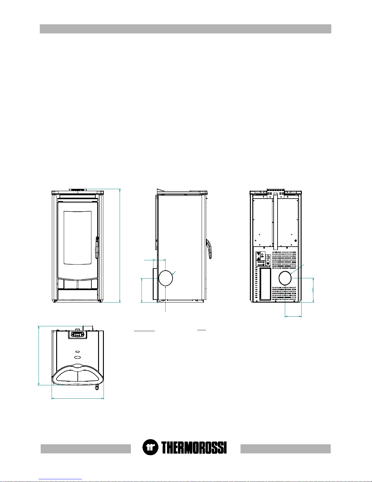
TECHNICAL CHARACTERISTICS *TECHNICAL CHARACTERISTICS *
TECHNICAL CHARACTERISTICS *TECHNICAL CHARACTERISTICS *
TECHNICAL CHARACTERISTICS *
* All the data are based on the appliance fuelled with Austrian standard ÖNORM
M 7135 type-approved pellets. Pellets consumption may vary depending on
length.
862
413
449
184
104
USCITA FUMI LATERALE SINISTRA
O 80
429
O 80
184
134
ECOTHERM 1000
Power min / max 2.5 Kw - 7 Kw
Smoke temperature ~220°C
Average smoke flow rate 9,3 g/s
Minimum draft 0.09 mbar
Smoke exhaust pressure switch yes
Smoke exhaust diameter mm 80
Dual combustion system yes
Hopper capacity Kg ~14
Pellets consumption min/max 0.5. - 1.4 Kg / h
Weight 85 Kg
Automatic lighting yes
6-speed fan-forced ventilation yes
5 power levels yes
Weekly chronothermostat yes
Adjustable mounting feet yes
KEY
left side smoke outlet
LEGENDA
uscita fumi laterale sinistra
Page 6
pg. 6
33
33
3
GENERAL DESCRIPTIONGENERAL DESCRIPTION
GENERAL DESCRIPTIONGENERAL DESCRIPTION
GENERAL DESCRIPTION
3.13.1
3.13.1
3.1
OPERAOPERA
OPERAOPERA
OPERA
TING TING
TING TING
TING
TECHNOLTECHNOL
TECHNOLTECHNOL
TECHNOL
OGYOGY
OGYOGY
OGY
•Your heater has been built to fully satisfy all your heating and practical requirements. Top-grade components and functions managed with
microprocessor technology guarantee high reliability and optimal performance.
3.33.3
3.33.3
3.3
THE FEEDBOTHE FEEDBO
THE FEEDBOTHE FEEDBO
THE FEEDBO
XX
XX
X
•The feedbox is situated in the top part of the heater.
•The maximum load capacity of the tank is approximately 14 Kg, but
varies according to the specific weight of the pellets.
The manufacturer recommends emptying the tank and vacuuming the
screw feeder zone once a month and during the summer period.
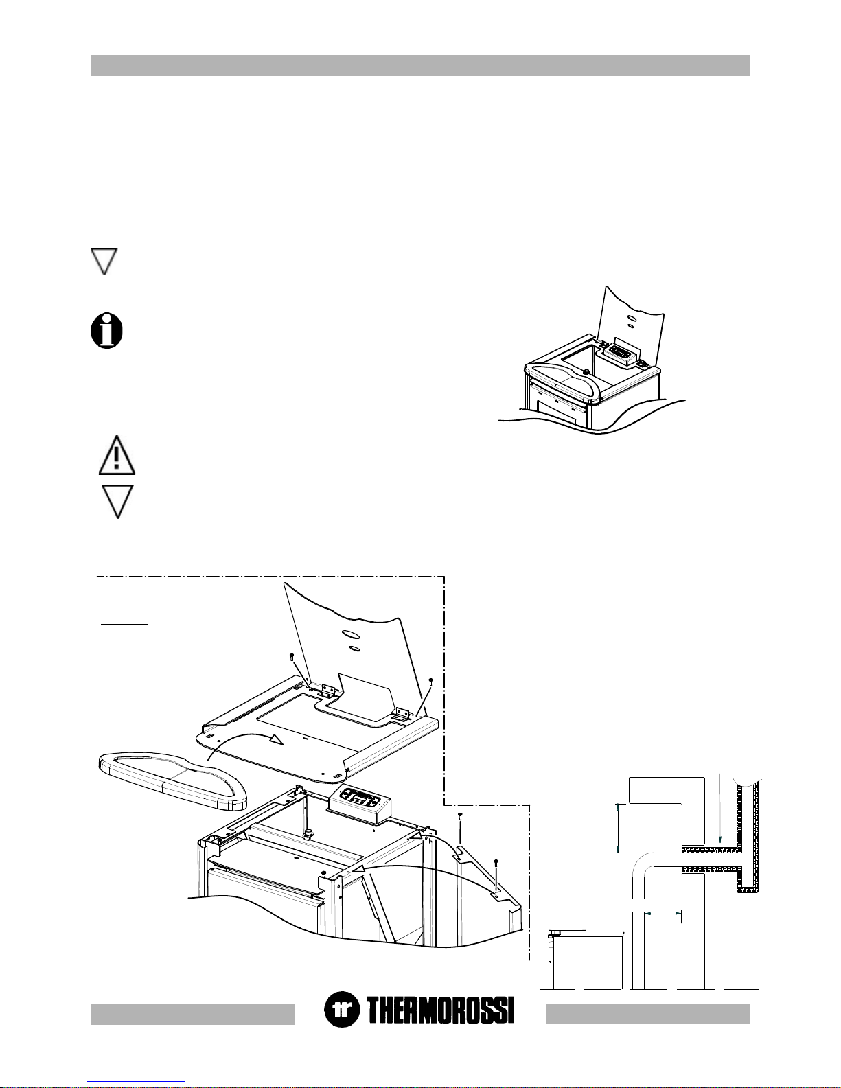
The appliance must be positioned at a minimum safe distance from walls and furnishings. This distance will have to be increased
considerably if the objects surrounding the appliance are inflammable (matchboarding, furniture, curtains, picture frames, sofas,
etc...). The recommended minimum distances are illustrated in the drawing below on the right. Installation in the vicinity of heatsensitive materials is only permitted if suitable insulating protection is placed between them and the heater (ref.Uni 10683).
Adjust the mounting feet to allow a 10 mm space between the floor and the heater.
ISOLANTE TERMICO
250 mm SE SOFFITTO IN MURATURA
450 mm SE SOFFITTO IN LEGNO
450 mm SE PARETE IN LEGNO
3.23.2
3.23.2
3.2
PELLETSPELLETS
PELLETSPELLETS
PELLETS
•The appliance is fuelled by pellets, that is, cylinders of compressed sawdust; this will make it possible for you to enjoy to the full the heat of
the flame
•The pellets are cylinders of compressed sawdust having a 6 mm diameter and a maximum length of 20 mm.
They have a maximum moisture content of 8%, a thermal value of 4000/4500 Kcal/Kg and a density of 620-630 Kg/m³.
All data presented in the table of Technical Features (para.2) are taken using pellets certified according to O M 7135 standards, the
consumption of pellets may vary depending on length.
The use of fuel which does not comply with the description given above immediately voids the warranty.
44
44
4
INSTINST
INSTINST
INST
ALLAALLA
ALLAALLA
ALLA
TIONTION
TIONTION
TION
4.14.1
4.14.1
4.1
HEAHEA
HEAHEA
HEA
TER LTER L
TER LTER L
TER L
OCAOCA
OCAOCA
OCA
TIONTION
TIONTION
TION
Follow the general guidelines set out in paragraph 1.1 to the letter. Above all keep in mind that the floor of the room must be capable
of bearing the weight of the heater. CAUTION: The heater must be installed in a room with adequate ventilation (minimum air int ake of
80 cm²).
FIGURA 1
4.1.14.1.1
4.1.14.1.1
4.1.1
INST INST
INST INST
INST
ALLAALLA
ALLAALLA
ALLA
TION OF METTION OF MET
TION OF METTION OF MET
TION OF MET
ALAL
ALAL
AL
COLCOL
COLCOL
COL
OR CASINGOR CASING
OR CASINGOR CASING
OR CASING
After the heater is put in place, the side panels must be assembled,
as well as the ceramic top and bottom as shown in figure 1-2.Carry
out the following operations:
- Remove the upper steel cover by means of the 2 screws shown.
-Mount the side panels by firstly inserting the bottom holes on the
folds of the base then fasten the 2 top screws. Then assemble the
upper cover fastening the 2 screws where indicated.
- Then rest the ceramic top attaching it with dots of silicone (thermal
silicone provided) to the steel support.
- Once the lower support has been cleaned, degreased and dried,
atttach the ceramic element to its support (wait 24 hours to make
sure that the silicone has completely dried before the heater is turned
on)
Remember that the heater must be completely cooled down before
the side panel can be cleaned with a soft cloth and water.
KEY
Figure
Heat
insulating
material
250 mm for a
masonry
ceiling
450 mm for a
timber ceiling
450 mm for a
timber wall
LEGENDA
Figura
Isolante
termico
250 mm se
soffitto in
muratura
450 mm se
soffitto in
legno
450 mm se
parete in legno
Page 7

pg. 7
All controls and indicators are presented here below :
(1) Insert on/off and flame adjustment button . When you press this button the appliance (10) switches to Star / ON / OFF. Up to 5 leds (10)
are activated when pressed repeatedly.
(2) Ventilation setting button . Press this button to set the desired level of ventilation: up to a maximum of 6 speeds are available, indicated by
the lighting of the corresponding leds (9).
(3) (4) Auxiliary setting keys.
Keys (3) and (4) are operating keys necessary when on-off cycles are programmed, for operative levels, clock setting, etc..
5) Programming Enable / Disable keys.
(6) “MENU” selection button To access the main menu press the button marked with 6. Press button 6 repeatedly to scroll the adjustment,
setting and programming windows (see para. 5.2 , 5.3 , 5.4) .
(7) Display
(8) Infrared sensor for remote control
(9) Ventilation level leds .
(10) Combustion level leds
1
2
34
5
6
7
8
9
10
55
55
5 DESCRIPTIONS OF CONTROLS
5.15.1
5.15.1
5.1
DESCRIPTION OF CONTRDESCRIPTION OF CONTR
DESCRIPTION OF CONTRDESCRIPTION OF CONTR
DESCRIPTION OF CONTR
OL POL P
OL POL P
OL P
ANEL ANEL
ANEL ANEL
ANEL
AND HEAAND HEA
AND HEAAND HEA
AND HEA
TER REAR PTER REAR P
TER REAR PTER REAR P
TER REAR P
ANELANEL
ANELANEL
ANEL
5.1.1 DESCRIPTION OF THE CONTROL PANEL
There are two main control pushbuttons marked with the ventilation symbol (2)
and the symbol of the flame (1).The flame pushbutton (1) sets the power of the
heater with 5 levels available which are activated as the 5 leds light up in
sequence (10). The off cycle is activated when all power leds are turned off. Key
(2) controls the ventilation of the heater. It is activated when the heater reaches a
temperature over 42 °C. The fan can be set to any of speed levels (9): when the
heater is on the ventilation cannot be switched off .
11
0
11
12
13
14 15
16
17
5.1.2 BACK PANEL OF THE HEATER
A description of the functions of the buttons and LEDs on the back panel of the
heater:
(11) Main switch 0-1
(12) Heater electrical power outlet 220-240V 50 Hz.
(13) Overtemperature thermostat button cap.
In the event of overtemperature this safety thermostat stops the loading of pellets.
When it is activated LED 15 comes on.
To restart the heater you need to wait until it cools down, then verify the cause for
the overheating, remove the cause, unscrew the protective cap and press the button
(13) .
(14) Feed motor test indicator light.When the pellet screw feeder is set in
motion the light must come on.
(15) Reset thermostat tripped indicator light. This LED comes on when the reset thermostat is activated.
(16) Power outlet for additional chronothermostat (see para.7) (additional chronothermostat not supplied)
(17) Power outlet for additional room temperature thermostat.(see para. 7) (additional room temperature thermostat not supplied)
FIGURA 2
Page 8

pg. 8
1
2
34
5
6
7
8
10
9
5.2 D5.2 D
5.2 D5.2 D
5.2 D
AA
AA
A
Y Y
Y Y
Y
AND AND
AND AND
AND
TIME SETTINGTIME SETTING
TIME SETTINGTIME SETTING
TIME SETTING
The heater must be fed and the rear switch in position “1”.”Display (7) may show the inscriptions On , OFF or Star.
.
To set the time and the day of the week carry out the procedures described
below.
Press once the key (6), and the inscription HoUr will flash. After a few
seconds the fixed inscription days will appear.In order to ad just the day,
repeatedly press key (4) and/or (3) until the led turns on in area (9) which
corresponds to the present day; Monday is indicated by the 1st led on,
Tuesday is indicated by the 2nd led on,....... Saturday is indicated by led
(6) on, while Sunday corresponds to all 8 leds being on. Then confirm the
day by pressing the key (1).The 2 digits representing the hours will start
flashing in the display:it is possible to select the present hour using the
arrow keys (4) and/or (3); the selection must be confirmed by pressing
key (1).The 2 digits indicating the minutes will start flashing: it is possible to select the present minutes using the arrow keys (4) and/or (3), the
selection must be confirmed by pressing the key (1).The setting of the day and of the hour is now completed. For the entire procedure to be
confirmed and to move back to the heater status display, key (6) must be repeatedly pressed until the operating status is displayed: On , Off, or
Star.
1
2
34
5
6
7
8
10
9
On
PRESENZA FISSA PUNTO
ESEMPIO DEL DISPLAY CON LA PROGRAMMAZIONE ATTIVATA
5.3 ON/OFF PROGRAMMING.5.3 ON/OFF PROGRAMMING.
5.3 ON/OFF PROGRAMMING.5.3 ON/OFF PROGRAMMING.
5.3 ON/OFF PROGRAMMING.
The heater must be fed with the rear switch in position “1”. Display (7) may show the inscriptions On , OFF or Star.
It is possible to carry out the weekly programming by setting up to 3 on/off
cycles for each day from Monday to Sunday. To carry out the programming,
push button (6) must be pressed twice until the inscription cr on is on.: in
area (9) a led goes on (which indicates that the first day of the week,
Monday, is being programmed).Inscription On1 will appear on the display,
and the 2 digits representing the hours will turn on. Press button (3) and/or
(4) to enter the hour of the first cycle start time. To confirm the selection
press the button (1). The two digits representing the minutes will be turn
on.Press button (3) and/or (4) to enter the minutes of the first cycle start
time. For the selection to be confirmed press the key (1). The first hour for
the Monday on-cycle has been set.Then the inscription OFF1 will appear in
the display and the two digits representing the hours will turn on. When the
(3) and/or (4) is pressed the hour of the first off-cycle is entered.To confirm the selection press the button (1). The two digits representing the
minutes will be turn on. By pressing the key (3) and/or (4) the minutes for the first off-cycle will be enteredTo confirm the selection press the
button (1). At this point the first on-off cycle for Monday has been entered. Later, it is possible to set the Monday’s second on-off cycle (shown
with the display of On2 and OFF2) and the third Monday’s on-off cycle (shown with the display On3 and OFF3) . Inside the programming menu,
if for example the Wednesday’s programming is to be changed, go to the third green led by pressing key(2): then it is possible to change the onoff programs for Wednesday. If the second on-off cycle is not required simply set the ON2 time as 00:00 and the OFF2 time as 00:00 .
The programming stage may be terminated by pressing the key (6), i.e. by quitting the programming menu. Pressing pushbutton (5) programming
is enabled/disabled (Enabled= message on cr temporarily displayed and, at the same time, a fixed point is present on the right side at the bottom
of the display.Disabled= message of cr temporarily displayed and, at the same time, the point on the right side at the bottom of the display is not
present.) : this function is useful if one wants to prevent the weekly established programming. With the programming active, the operating
conditions at the start-up (combustion power – ventilation speed) are the same as set-up before the last off-cycle of the heater.
In order to display the present time and programmings, key (6) must be repeatedly pressed until the current time is displayed.By pressing keys
(3) and/or (4) all programming values will be displayed :to exit this condition, twice press the key (6) .
On
ASSENZA PUNTO
ESEMPIO DEL DISPLAY CON LA PROGRAMMAZIONE DISATTIVATA
KEY
Example of the display
with the programming
activated/deactivated
Point steady presence
Point absence
LEGENDA
Esempio del display
con la programmazione
attivata/disattivata
presenza fissa punto
assenza punto
In the event of a programmed cycle on always ensure that the brazier is clean and seated correctly in its lodging: failure to keep the
brazier clean can reduce the life of the spark plug.
Page 9

pg. 9
5.4 OPERA5.4 OPERA
5.4 OPERA5.4 OPERA
5.4 OPERA
TING LEVEL SETTINGTING LEVEL SETTING
TING LEVEL SETTINGTING LEVEL SETTING
TING LEVEL SETTING
The heater must be fed and the rear switch in position “1”. Display (7) may show the inscription On , OFF or Star .
Y our appliance is delivered with an excellent program installed that favours combustion yield; the program is called P 1.
If you are using pellets with an out-of-standard incidence of residues after combustion in the brazier, alternative levels may be selected:
P 2 : this program increases the smoke suction unit speed acceleration.
P 0 : when using too long pellets and/or flue outlets with very high vacuum, over 2 mm water column.
The pellet consumption value is not affected by the operating level settings.
Select the required level by acting as follows:
Repeatedly press three times the key (6) until the inscription LIV flashes on the display and, then, the corresponding level set on the heater
will show ( P1 o P2 o P0) In order to change the operating level as key (4) is kept pressed, press the key (3).
By holding down button (4) and pressing button (3) repeatedly the level changes in the following sequence: P2... ...P0 ... P1.
If the change is made while the insert is running the difference in the flame will be apparent. It is mandatory to pay
particular care when selecting the most appropriate operating cycle for your installation. After the selection of the
operating cycle a thorough cleaning of the brazier is mandatory.
1
2
34
5
6
7
8
9
10
66
66
6
USE OF USE OF
USE OF USE OF
USE OF
THE HEATHE HEA
THE HEATHE HEA
THE HEA
TERTER
TERTER
TER
6.16.1
6.16.1
6.1
5.15.1
5.15.1
5.1
SWITSWIT
SWITSWIT
SWIT
CHING ON CHING ON
CHING ON CHING ON
CHING ON
THE HEATHE HEA
THE HEATHE HEA
THE HEA
TERTER
TERTER
TER
Before using the appliance check that all the movable parts are in place; also remove any labels and stickers from the glass to avoid having
permanent traces remain on the surfaces.
Turn the switch installed on the back of the heater to position “1” (= ON). Press button (1) to start the start up phase. When key (1) is
repeatedly pressed, the desired combustion level can be set and it will be active at the end of the ignition stage.
The electrical heater will start to overheat and after a few minutes the first lot of pellets will start dropping into the brazier. This occurs
because the screw feeder has to fill up because it is completely empty. The first time the heater is started up the start up phase will have to
be carried out twice for this very reason.
CAUTION : The start up phase (word Star appearing on the display) takes 20 minutes during which the heater ignores any
commands transmitted to it. After this time has elapsed the word ON appears on the display. The fan starts as soon as the heater
body exceeds 42°C. During the work stage it is then possible to adjust combustion and the ventilation: Combustion is adjusted by 5
leds (through key (1)) , while the ventilation adjustment is distributed over 6 levels shown by the leds that turn on in succession
(through key (2)).
For an overall confirmation and to return to the status display of the heater, repeatedly press the key (6) until the operating status is
displayed. It is possible to set back the operating level to P1 by keeping the key (5) pressed for 8 seconds until the display shows the inscription
rESt : this operation may be carried out when the display shows the inscription ON or OFF or StAr.
When the programming is enabled (temporary inscription on cr on the display and, at the same time, a fixed point is present on the
right side at the bottom of the display) any additional chronothermostat (see para.7.2) is deactivated.
Programming can be reset by keeping key (5) pressed for 8 seconds until the inscription rESt is displayed: this operation can be carried out
when the inscriptions On or OFF or StAr are shown on the display.
To turn the heater on it is necessary for the inscription OFF to be present on the display; if it is not present, the key (6) must be repeatedly
pressed until the inscription OFF appears.
Page 10

pg. 10
CAUTION: In the event of connections to the chronothermostat Thermorossi shall not be held responsible for the insert not
starting up, smoke leaks, breakage of the lighting component. In the event of a programmed cycle on always ensure that the
brazier is clean and seated correctly in its lodging.
7.2 OPERATING WITH THE ADDITIONAL CHRONOTHERMOSTAT (NOT SUPPLIED )
It is possible to install, as an alternative to the additional room thermostat, a chronothermostat that must be connected by means of a jack to
the back of the Ecotherm heater in the socket marked “CHRONOTHERMOSTAT” (see drw. para.5.1). Using this outlet when the
chronothermostat contact closes the ON cycle starts, whereas when the contact opens the OFF cycle starts. The operating level at start up
(combustion power - fan speed ) is the same as the level used before the last time the heater shut down. This operation can also occur by
adjusting its room temperature. Once the desired temperature set on the chronothermostat is reached the contact opens and executes the
shut down cycle. Similarly when the room temperature drops below the set temperature the contact closes and the ON cycle starts. If an
unsuitable room temperature value is selected the heater will be subjected to continual ON-OFF cycles, consequently the increased number
of start ups will result in greater consumption of electrical energy. The chronothermostat can be used to program temperatures, times and
dates for the ON-OFF cycles. It is therefore possible to program a momentary shutting down of the heater according to the room temperature.
CAUTION: The manufacturer denies all responsibility for the life of the electrical heater if subjected to excessive start ups. The
manufacturer recommends setting a suitable room temperature value in the chronothermostat in order to prevent this possibility.
CAUTION: Use N.O. (normally open) contacts for the connection to the chronothermostat. Contact 1-3 of the chronothermostat
mod. “Perry”.
The heating capacity is adjusted by pressing key (1) or on the remote control provided . Act on this command to adjust the quantity of pellets fed to
the firebox. Maximum combustion power is achieved when all 5 leds are lit.
Caution: The fan starts as soon as the heater body exceeds 42°C. The fan setting is expressed visually by means of 6 different
positions represented by 6 bars: press button (2) repeatedly to regulate it.
6.2 HEATER COMBUSTION AND VENTILATION ADJUSTMENTS
7 ADDITIONAL ROOM TEMPERATURE THERMOSTAT / ADDITIONAL CHRONOTHERMOSTAT
(not supplied)
Y our heater is already provided with all programming functions:
Two connectors are located on the back of the heater near the electric power socket.
They refer to two operating modes:
à With the room temperature thermostat. à With the chronothermostat or modem.
Procure a jack where the 2 wires are to be welded as illustrated in the diagram:
Use only contacts 1 and 2, do not use contact 3 .
Contacts 1-2 are defined as “CLEAN” contacts and they must never be fed with 220 V. If the board is energised with 220V or
voltages exceeding 6 V the control board will be permanently damaged and will not be covered by the GUARANTEE.
7.1 OPERATING WITH THE ADDITIONAL ROOM TEMPERATURE THERMOSTAT (NOT SUPPLIED )
It is possible to install an additional room temperature thermostat by connecting it to the back of the Ecotherm heater, by inserting a jack in the
socket marked “THERMOSTAT” (see drw. para.5.1). This stereo jack is not supplied with the heater but is readily available in electrical or
stereophonic equipment supply stores. The operating principle is as follows:
-When the room temperature reaches the set temperature (only during the RUNNING phase) the thermostat closes the contact and the heater
shifts to the minimum room fan speed and minimum combustion power. By using the room temperature thermostat the heater does not shut
down, therefore electrical energy consumption is kept to the minimum and the heater has a longer life.
-When the room temperature drops the thermostat opens the contact and the heater returns to its original position in terms of thermal power
and ventilation.
-In this position it is not possible to start up the heater automatically or shut it down automatically.
CAUTION: N.C. (normally closed) contacts must be used for the connection to the additional room temperature thermostat. Contacts
1-2 of the chronothermostat mod. “Perry”.
When the programming is enabled (temporarily shown on the cr display, with the fixed presence, at the same time, of a point on
the right side at the bottom of the display of the control panel (refer to par. 5.3)) any additional chronothermostat (refer to par. 7.2)
is disabled.
Page 11

pg. 11
88
88
8
CLEANING AND MAINTENANCECLEANING AND MAINTENANCE
CLEANING AND MAINTENANCECLEANING AND MAINTENANCE
CLEANING AND MAINTENANCE
8.18.1
8.18.1
8.1
FOREWORDFOREWORD
FOREWORDFOREWORD
FOREWORD
Before beginning any maintenance operation ensure that the appliance is in the OFF phase and disconnect it from the electric
power outlet.
Your pellet heater / boiler ECOTHERM is a solid fuel generator : it requires frequent controls and general cleaning operations. This
will guarantee regular operation and optimal output at all times. If the product is unused for a prolonged period of time it is
mandatory to inspect the smoke channel and outlet to ensure that there are no obstructions before use . It is necessary to
accurately follow the directions given below: Otherwise severe damages may occur for the product, the installation, objects and
the people who use the generator.
8.28.2
8.28.2
8.2
CLEANING CLEANING
CLEANING CLEANING
CLEANING
AND MAINTAND MAINT
AND MAINTAND MAINT
AND MAINT
AINING AINING
AINING AINING
AINING
THE HEATHE HEA
THE HEATHE HEA
THE HEA
TERTER
TERTER
TER
• EVERY DAY clean out all the combustion residues from the brazier and remount the brazier and catalyst blade (figure 2 below).
• EVERY 2 DAYS empty the ash pan “V” of all residual ash (figure 3).
• EVERY WEEK vacuum the residual ash from the compartment “V1” under the brazier (figure 3).
• EVERY 2 WEEKS clean the smoke exhaust “T” at the heater inlet .
• EVERY MONTH inspect and clean the vents identified as “A1” , “A2”. To access vent “A2” (figure 1) remove the cover “A3” by pressing
the two side folds inwards and rotating it upwards. In order to access vent “A1” (figure 4) remove the steel cover complete with ceramic
(to remove it unscrew the 2 screws as indicated in par,.4.1.1). Unscrew the screw on the air deviator blade and pull the blade out from its
housing: now you can access the vent “A1”.
• EVERY MONTH clean the grate of the room fan, positioned as in figure 5.
• EVERY MONTH check that the smoke exhaust is free from fly ash deposits, particularly in the initial sections.
• EVERY MONTH vacuum the pellet ash deposited on the bottom of the tank (when the tank is empty).
• AT THE END OF THE WINTER SEASON OR WHENEVER NECESSARY we recommend thoroughly cleaning the Ecotherm firebox, using
brushes and vacuum cleaner.
• TWICE A YEAR clean the smoke exhaust, including the flue outlet.
A vacuum device simplifies the cleaning procedure. Use a damp cloth or a scrunched up piece of newspaper, dampened and
rolled in the ash, to wipe the glass until it is perfectly clean. Do not clean the glass while the heater is operating. The glass
remains reasonably clean if the catalyst - deviator blade is installed correctly in the brazier as shown in figure 2. The heater
must be completely cooled down before the side panel can be cleaned with a soft cloth and water.
A3
A2
LAMA CATALIZZATRICE
V
FIGURA 1
FIGURA 2
FIGURA 3
FIGURA 4
FIGURA 5
GRIGLIA VENTILATORE
A1
V1
KEY
figure
catalyst blade
fan grate
LEGENDA
figura
lama catalizzatrice
griglia ventilatore
Page 12

pg. 12
9.19.1
9.19.1
9.1
VENTILAVENTILA
VENTILAVENTILA
VENTILA
TION OF TION OF
TION OF TION OF
TION OF
THE RTHE R
THE RTHE R
THE R
OOMSOOMS
OOMSOOMS
OOMS
•The room where the heater is installed must have a good air flow to guarantee secondary air for the appliance for the combustion process and
for ventilation of the room. The natural air flow occurs directly through permanent apertures to the outside made in the walls of the room, or by
means of single or multiple ventilation ducting.
The ventilating air must come from outside and if possible, away from sources of pollution. Indirect ventilation is also allowed by taking in air from
rooms adjacent the one where the insert eater is installed taking into account all the warnings and limitations specified below.
•The apertures in the walls must comply with the following requirements:
- -have an unobstructed section of at least 6cm² for each Kw of installed thermal power, with a minimum limit of 100cm²;
- be made in such a way that the vent openings, both on the inside and outside of the wall, cannot be obstructed;
- be protected with grills or similar systems in order not to reduce the section described above;
- be situated at floor-level.
•The air flow can also be obtained from an adjacent room as long as:
- the adjacent room is equipped with direct ventilation in compliance with the points described above;
- in the room to be ventilated the installed appliances are only connected to one flue outlet;
- the adjacent room is not used as a bedroom or a common area of the building;
- the adjacent room is not a room with a fire hazard, such as storage sheds, garages, combustible material store rooms;
- the adjacent room does not become a vacuum compared to the room to be ventilated due to an opposite draught effect;
- the air flow from the adjacent room to the room to be ventilated is unobstructed through the permanent apertures having an overall net section
of no less than that indicated above. These apertures can be obtained by enlarging the space between the door and the floor.
This chapter is not intended to replace UNI 7129/92, UNI 10683 and EN 14785 standards to which it refers. The
qualified installer must in any case be fully aware of this standard and its amending versions.
8.3 REPLACEMENT OF THE REMOTE CONTROL BATTERY
When the infrared remote control does not send out the transmission signal (led on), the battery must be replaced. Use a Phillips screwdriver
of proper size, to separate the half shells and replace the battery. When the dead battery is removed, it must be safely disposed of.
BATTERIA TAMPONE CR2032
8.4 CONTROL PANEL BUFFER BATTERY REPLACEMENT
Inside the control panel there is a buffer battery type CR2032 . . When hour and programming are not kept in storage , the battery must be
replaced using the 2 screws in the rear of the control panel. The dead battery, after it is removed, must be safely disposed of.
99
99
9
SMOKE DISCHARGE TUBESMOKE DISCHARGE TUBE
SMOKE DISCHARGE TUBESMOKE DISCHARGE TUBE
SMOKE DISCHARGE TUBE
Due to the frequent accidents caused by poor functioning of flue outlets installed in private dwellings, we have prepared the
following paragraph to assist the installer in his inspection of the parts concerned with eliminating the gases produced by
combustion. The smoke exhaust must be installed in compliance with UNI7129/92 , UNI 10683 and EN14785 and must respect the
following reference values: T. Smoke discharge ~ 220°C Discharge smoke flowrate ~ 9,3 g/s Required draft ~ 0,09 mbar The
instructions provided in the regulations mentioned above must be accurately followed: Non-observance may cause serious
damages to the product, to objects and to people who make use of the generator.
KEY
Buffer battery
CR2032
LEGENDA
batteria tampone
CR2032
Page 13

pg. 13
9.29.2
9.29.2
9.2
SMOKE OUTLETSMOKE OUTLET
SMOKE OUTLETSMOKE OUTLET
SMOKE OUTLET
•The smoke exhaust shown in the following figures is the best solution to ensure the discharge of smoke even when the fan is not operational,
such as for example if there is an electrical power failure. A minimum drop of 1.5 metres is required between the T terminal on the outside of the
building and the outlet at the back of the appliance, to ensure that residual combustion smoke is discharged in the case described above
(Otherwise the residues would stagnate inside the firebox and be discharged out to the free atmosphere).
The figures below illustrate the best solution for discharging the smoke out through the roof or into the flue outlet. If you opt to discharge the
smoke out through the roof it is important to operate as shown in the figure below on the left. Insert a union tee with inspection cap, connecting
brackets suitable for the height of the flue outlet, flashing that crosses the roof and chimney cap to protect against bad weather conditions. If you
decide to use a classic masonry outlet see the diagram below on the right. A union tee with inspection cap and suitable supporting brackets are
required. If the flue outlet is too big we recommend inserting a stainless steel or porcelain-coated steel tube with a
diameter not exceeding 150mm. Seal area where the inlet and outlet part of the smoke exhaust meets the wall. It is
strictly forbidden to apply mesh to the end of the outlet tube, as it could cause the heater to malfunction. If the
smoke tube is installed in a fixed position it is advisable to provide inspection openings for clean-out purposes especially
in the horizontal sections. See the diagram. These openings are essential to allow for the removal of ash and unburned
products which tend to accumulate along the discharge path.
The appliance functions with the firebox in a vacuum, while the discharge of smoke to the flue outlet
has a slight pressure, consequently it is imperative to ensure that the discharge system is hermetically
sealed. The smoke discharge tube must be made from suitable materials such as for example: porcelain-coated
steel tubes, and the various fittings sealed with red silicone (resistant to 350°C). The outer casing of the tube must
be made with insulating material (mineral wool, ceramic fiber) or use pre-insulated tubing.
If the side outlet is used take care not to damage
the silicone tube that connects the pressure
switch.
It must be possible to inspect and remove all
the smoke tube sections for clean-out
purposes.
KEY
Inspection
Slope
Height more than 4m
Internal
External
Rain protection
Cover slab
Watertight steel sheet
LEGENDA
Ispezione
Pendenza
Altezza superiore a 4m
Interno
Esterno
Protezione dalla pioggia
Lastra di copertura
Lamiera di acciaio a
tenuta stagna
Page 14

pg. 14
1111
1111
11
ELECTRICAL WIRINGELECTRICAL WIRING
ELECTRICAL WIRINGELECTRICAL WIRING
ELECTRICAL WIRING
1010
1010
10
ALARMSALARMS
ALARMSALARMS
ALARMS
RESISTENZA
MOTORE CARICO
PELLETS
TERMOSTATO RIARMO
MANUALE
ASPIRATORE FUMI
VENTILATORE
AMBIENTE
220-240 V
50 Hz
CRONOTERMOSTATO
(AGGIUNTIVO)
TERMOSTATO AMB.
(AGGIUNTIVO)
PRESSOSTATO
TERMOSTATO 95°C
TERMOSTATO 42°C
SCHEDA COMANDO
The heater is programmed to communicate 3 fundamental alarms. The alarms are listed below:
PE OF : is communicated when the temperature during the On mode drops below 42 °C.
This indicates that the heater is switching off due to lack of pellets.
AL AC : is communicated if after the start up phase the temperature does not rise above 42°C.
AL OP : this occurs when the smoke outlet is partially blocked.
In order to set the alarms to zero, the feed to the heater must be turned off and restored using switch 0-1 on the back of the heater.
KEY
Heater
Pellet feed indicator
Manual thermostat
Smoke suction unit
Room fan
Chronothermostat
(additional)
Room thermostat
(additional)
Pressure switch
Thermostat 95°C /
42°C
LEGENDA
Resistenza
Indice carico pellets
Termost ato manuale
Aspiratore fumi
Ventilatore ambiente
Cronotermostato
(aggiuntivo)
Termostato amb
(aggiuntivo)
Pressostato
Termost ato 95°C/
42°C
Page 15

pg. 15
1212
1212
12
INFORMAINFORMA
INFORMAINFORMA
INFORMA
TION FOR TION FOR
TION FOR TION FOR
TION FOR
THE SKILLED THE SKILLED
THE SKILLED THE SKILLED
THE SKILLED
TECHNICIANTECHNICIAN
TECHNICIANTECHNICIAN
TECHNICIAN
12.1 MAIN COMPONENTS AND THEIR OPERATION
SMOKE PRESSURE SWITCH
This is a safety switch that stops the screw feeder motor whenever necessary. The main cause for the pressure switch tripping is a blocked
flue outlet or smoke exhaust pipe. Note that it is strictly forbidden to apply any kind of mesh screen to the end of the pipe. When the holes of the
mesh clog up they create a plug that trips the pressure switch which stops the pellet feeder.
SCREW FEEDER MOTOR
This motor is powered at regular on/off intervals controlled by a microprocessor. The operation of this motor is affected when:
-The motor’s thermal cutout trips. -The pressure switch trips due to blocked smoke exhaust.
-Pellets finished. -The heater is switched off intentionally .
-The manual reset thermostat trips at 125°C
ROOM FAN
The fan starts automatically as soon as the 42°C thermostat closes the contact. The fan stops when the fuel hopper is empty or when the insert
is switched off intentionally, two situations in which the thermostat’s contact is opened.
SMOKE SUCTION UNIT
This is activated when the start up signal is given. In the first two minutes it «washes» the smoke discharge tube, that is, it functions at maximum
working rate. Once this time has elapsed it self-adjusts to the optimal speed. The exhaust continues to operate for approximately one hour from
the time the heater is switched off to allow for the evacuation of all the smoke and for safety purposes. It stops 30’ after the thermostat at 42°C
opens.
THERMOSTAT AT 42°C
Its function is critical for the following reasons: When the contact closes the heater powers up and the working cycle starts. Similarly, when the
contact opens the smoke exhaust stops.
HOPPER SAFETY THERMOSTAT
This thermostat start operating as soon as the temperature in or near the pellet hopper approaches 85°C and sends an immediate signal to the
room fan to operate at maximum power.
125°C MANUAL RESET THERMOSTAT
When the temperature exceeds 125°C the pellet feed screw shuts down. A red light at the back of the appliance remains lit. Once the causes for
the overtemperature have been identified and remedied the heater can be reactivated by unscrewing the plastic cover of the thermostat located
at the back of the heater and pressing the button (the heater temperature must be below 117 °C ).
GLOW PLUG
It is activated in the Star phase. Heats the air to 800°C, which assist the first combustion of the pellet s present in the brazier.
12.2 USEFUL ADVICE FOR INSTALLATION AND OPERATION
1 The appliance must never be deliberately disconnected from the electric power supply. Whenever the appliance is deliberately disconnected
from the electric power supply smoke could be emitted into the room and be a hazard. Similarly never switch off the appliance by suddenly
cutting off the electric power supply.
2 Do not install the appliance with horizontal wall outlets only: evacuation of the combustion products must be guaranteed in a natural manner.
3 Do not install the appliance with horizontal sections only: the wall could be exposed to high wind conditions and the appliance could shut
down due to back draft.
4 Operate the appliance at maximum for 1 hour for a complete drying and baking of the silicates contained in the enamel which covers the body
of the heater.
5 Do not install a grill or outlet terminal which could restrain the flow of the combustion gases: this could affect the dynamic gas to the point
where it would not allow the pellets to burn correctly.
6 Read this instruction booklet.
7 Keep the appliance clean and check the burner as described in this manual.
8 Clean the smoke outlet regularly.
9 Use top quality pellets: by saving 20 cents a bag you heat up to 50% less.
10 Maximum useable lengths of smoke exhaust tubes:
Painted aluminized steel tubes (1.5 mm minimum thickness), Aisi 316 stainless steel tubes or 0.5 mm enamelled tubes may be used.
Minimum vertical length 4 m
Maximum vertical length 8 m
Length with min slope .5% 0.5 m
Maximum number of elbows at least 0.5 m apart 2
Page 16

pg. 16
12.3 TROUBLESHOOTING CAUSE-SOLUTION
PROBLEM CAUSE SOLUTION
PELLET TANK IS EMPTY
(THE INSCRIPTION
PE OF
IS PRESENT IN THE
DISPLAY)
FILL UP THE TANK
FOREIGN BODY SUCH AS NAIL, NYLON,
PIECE OF WOOD ON THE FEEDER SCREW ON
THE BOTTOM OF THE TANK (THE
INSCRIPTION
PE OF
IS PRESENT IN THE
DISPLAY)
REMOVE THE FOREIGN BODY
SMOKE EXHAUST NOT FREE, OR WITH
TERMINAL THAT OBSTRUCTS THE PASSAGE
OF SMOKE
(THE INSCRIPTION
AL OP
IS
PRESENT IN THE DISPLAY)
CHECK THE SMOKE EXHAUST AS IT
COULD BE DIRTY OR CLOGGED
OUTLET TERMINAL CLOGGED BECAUSE A
GRILL OR TERMINAL HAS BEEN INSERTED
WHICH PREVENTS THE FREE PASSAGE OF
SMOKE
(THE INSCRIPTION
AL OP
IS PRESENT IN THE
DISPLAY)
REMOVE THE TERMINAL AND REPLACE IT
WITH A MORE SUITABLE ONE.
SUDDEN GUST OF WIND WHICH HAS MADE
THE APPLIANCE GO INTO SAFETY MODE.
(THE INSCRIPTION
AL OP
IS PRESENT IN THE
DISPLAY)
SWITCH THE POWER SUPPLY TO THE
APPLIANCE OFF THEN BACK ON AGAIN.
THE PELLETS SCREW MOTOR DOES NOT WORK REPLACE THE PELLETS SCREW MOTOR
PELLETS DO NOT DROP
INTO THE BURNER
THE RESET THERMOSTAT TRIPS AND LOCKS
THE GEARMOTOR
THE ROOM FAN IS BROKEN AND MUST BE
REPLACED; THEN, PUT BACK INTO SERVICE
THE RESET THERMOSTAT, WAIT UNTIL THE
HEATER COOLS DOWN AND RESET THE
THERMOSTAT (PARA. 12).
THE GRATE OF THE FAN IS VERY DIRTY AND
MUST BE CLEANED (SEE TO PARA. 8.2), THEN
SET THE THERMOSTAT BACK INTO SERVICE;
WAIT FOR THE HEATER TO COOL DOWN
AND RESET THE THERMOSTAT (SEE PARA
12).
SMOKE EXHAUST NOT FREE, OR WITH
TERMINAL THAT OBSTRUCTS THE PASSAGE
OF SMOKE
REMOVE THE TERMINAL AND REPLACE IT
WITH A SUITABLE TERMINAL. CHECK THE
SMOKE EXHAUST AS IT COULD BE DIRTY
OR CLOGGED
BURNER IS DIRTY
CLEAN THE BURNER ON A MORE
FREQUENT BASIS
;
CARRY OUT ALL THE CLEANING
OPERATIONS INDICATED (SEE PARA. 8.2)
PELLETS WITH DEPOSIT ABOVE
PERMISSBILE LIMITS
CLEAN THE BURNER MORE OFTEN.
SET OPERATING PROGRAM P2.
THE BURNER IS NOT PROPERLY PLACED ON
ITS SEAT
SET THE BURNER ON ITS SEAT PROPERLY
THE APPLIANCE
ACCUMULATES PELLETS
IN THE BRAZIER WHILE
OPERATING
THE BURNER STAYS LIFTED FROM ITS SEAT SET THE BURNER ON ITS SEAT PROPERLY
OCCURS THE FIRST TIME THE HEATER IS
SWITCHED ON AS THE SILICONE PAINT IS
BEING BAKED
RUN THE HEATER AT FULL POWER FOR 1
HOUR TO COMPLETE THE BAKING.
THE SMOKE EXHAUST IS NOT SEALED
CORRECTLY
MAKE SURE THAT THE GASKETS HAVE
BEEN FITTED TO THE SMOKE EXHAUST
PIPES
IF THE APPLIANCE STARTS TO SMOKE
AFTER 25 MINUTES: DIRTY BURNER, VERY
DELAYED START
CLEAN THE BURNER
THE APPLIANCE SMOKES
IF THE APPLIANCE STARTS TO SMOKE
AFTER 25 MINUTES: DELAYED START
BECAUSE THE SCREW FEEDER IS EMPTY
FILL UP THE TANK
DELAYED START BECAUSE THE SCREW
FEEDER IS EMPTY
(THE INSCRIPTION
AL AC
IS PRESENT IN THE
DISPLAY)
FILL UP THE TANK
DIRTY BURNER, VERY DELAYED START
(THE INSCRIPTION
AL AC
IS PRESENT IN THE
DISPLAY)
CLEAN THE BURNER
THE APPLIANCE SHUTS
OFF 5 MINUTES AFTER
THE END OF THE START
UP CYCLE
THE 42°C THERMOSTAT IS FAULTY.
(THE INSCRIPTION
AL AC
IS PRESENT IN THE
DISPLAY)
REPLACE THE THERMOSTAT
THE HEATER DOES NOT
START UP
THE SPARK PLUG IS BLOWN
(THE INSCRIPTION
AL AC
IS PRESENT IN THE
DISPLAY)
REPLACE THE SPARK PLUG.
Page 17

pg. 17
THE APPLIANCE ACCUMULATES PELLETS
IN THE BRAZIER
SEE POINT “PROBLEM-CAUSE-SOLUTION”
“THE APPLIANCE ACCUMULATES
PELLETS IN THE BRAZIER WHILE
OPERATING”
NO CAUSE
CLEAN THE GLASS MORE OFTEN
THE GLASS IS COVERED IN
BLACK SOOT
STEEL BLADE NOT PLACED CORRECTLY OR
MISSING
PLACE THE BLADE CORRECTLY OR
INSTALL IT
ABSENCE OF FLOW OF
VENTILATION AIR
VENTILATION GRATE DIRTY CLEAN THE VENTILATION GRATE
FOLLOWING THE INSTRUCTIONS
PRESENTED IN THIS MANUAL
THE HEATER OPERATES AT INTERVALS. THE HEATER MUST OPERATE FOR MORE
HOURS WITH MORE POWER
THE ROOM IS TOO LARGE, THE WALLS ARE
COLD
SEPARATE THE SPACES. THE HEATER
SHOULD OPERATE FOR MORE HOURS AND
WITH MORE POWER.
IT DOES NOT WARM UP
CEILINGS TOO HIGH OR PRESENCE OF STAIRS
THAT DISPERSE THE HEAT ELSEWHERE.
SEPARATE THE SPACES. THE HEATER
SHOULD OPERATE FOR MORE HOURS AND
WITH MORE POWER.
THE APPLIANCE IS OFF
BUT THERE ARE UNBURNT
PELLETS IN THE BRAZIER
THE TANK IS EMPTY EMPTY THE BURNER AND FILL UP THE
TANK.
PROGRAMMING AND/OR
TIME ARE NOT STORED
THE BUFFER BATTERY CR2032 INSIDE THE
CONTROL PANEL IS FLAT
REPLACE THE BATTERY (SEE PARA. 8.4)
Page 18

pg. 18
70012922
70012849 BEIGE
70012851 CUOIO
70012850 ROSSO
70012924
70012903 (completo)
70012853 BEIGE
70012855 CUOIO
70012854 ROSSO
60012690 BEIGE
60012688 CUOIO
60012689 ROSSO
60012693 BEIGE
60012691 CUOIO
60012692 ROSSO
70012853 BEIGE
70012855 CUOIO
70012854 ROSSO
70011479
1313
1313
13
SPSP
SPSP
SP
ARE PARE P
ARE PARE P
ARE P
ARAR
ARAR
AR
TS FOR ECOTS FOR ECO
TS FOR ECOTS FOR ECO
TS FOR ECO
THERM 1000THERM 1000
THERM 1000THERM 1000
THERM 1000
KEY
(Complete)
Beige
Leather
RED
Door gasket
Glass gasket
Glass
Steel door
Complete door
Back half-shell
Front half-shell.
Handle
Panel
Plate
Battery CR2032
Therm. 95°C/42°C
LEGENDA
(Completo)
Beige
Cuoio
Rosso
Guarnizione porta
Guarnizione vetro
Vetro
Porta acciaio
Porta completa
Semiguscio post.
Semiguscio anter.
Maniglia
Pannello
Targhetta
Batteria CR2032
Term. 95°C/42°C
Page 19

pg. 19
70011479
60005254
60010343
Term. 42°c
70012930
60010344
Term. 95°c
70012969
70012933 Pannello
60012695 Targhetta
60012787 Batteria CR2032
60011528 Semiguscio post.
70012917
70011242
60011527 Semiguscio anter.
70012916 Maniglia
60011750
60011656
70012932
70012908 Porta completa
70012909 Porta acciaio
60006693 Vetro
60009218 Guarnizione vetro
60007534 Guarnizione porta
60006637
70012898
Page 20

pg. 20
70012932
60010185
60010185
70010402
60011428
70010325
60004241
70010234
60011246
60006682
60006694
70012889 Ventilatore Completo
60005964 Ventilatore
60005553 Griglia
60010188
70012316
60011428
60010149
6
60011630
C
O
70012315
600101
9
KEY
Complete fan
Fan
Grate
Condenser
LEGENDA
Ventilatore completo
Ventilatore
Griglia
Condensatore
 Loading...