

THERMOROSSI DORICA METALCOLOR, DORICA MAIOLICA, DORICA PLUS METALCOLOR, DORICA PLUS MAIOLICA Installation, Use And Maintenance Manual


Page 2
manutenzione
INDEX
“EC” DECLARATION OF CONFORMITY................................................................................................. 0
1 - INTRODUCTION .................................................................................................................................. 0
1. 1 GENERAL GUIDELINES .................................................................................................................................0
1.2 SAFETY GUIDELINES .....................................................................................................................................0
1.2.1. RECOMMENDATIONS............................................................................................................................................................0
1.2.2 GENERAL GUIDELINES...........................................................................................................................................................0
1.3 TRANSPORTATION AND STORAGE..............................................................................................................0
2 – TECHNICAL CHARACTERISTICS*.................................................................................................... 0
3 – GENERAL DESCRIPTION.................................................................................................................. 0
3.1 OPERATING TECHNOLOGY...........................................................................................................................0
3.2 PELLETS...........................................................................................................................................................0
3.3 THE FEEDBOX.................................................................................................................................................0
4 - INSTALLATION ................................................................................................................................... 0
4.1 POSITIONING OF THE APPLIANCE...............................................................................................................0
4.2 UNPACKING THE APPLIANCE ......................................................................................................................0
4.3 UNPACKING THE MAJOLICA CASING AND THE METALCOLOR CASING................................................. 0
4.4 MOUNTING MAJOLICA CASING DORICA DORICA PLUS ...........................................................................0
4.5 MOUNTING METALCOLOR CASING DORICA DORICA PLUS .....................................................................0
4.6 CONNECTING THE APPLIANCE TO THE FLUE OUTLET.............................................................................0
4.7 HANDLE............................................................................................................................................................0
5 – DESCRIPTIONS OF CONTROLS ....................................................................................................... 0
5.1 DESCRIPTION OF CONTROL PANEL AND REAR PANEL ...........................................................................0
5.1 DESCRIPTION OF THE CONTROL PANEL................................................................................................................................0
5.1.2 APPLIANCE REAR PANEL.......................................................................................................................................................0
5.2 DAY AND TIME SETTING................................................................................................................................0
5.3 ON/OFF PROGRAMMING...............................................................................................................................0
5.3.1 ON-OFF PROGRAMMING DISPLAY........................................................................................................................................0
5.4 OPERATING LEVEL SETTING ........................................................................................................................0
6 – USE OF THE APPLIANCE.................................................................................................................. 0
6.1 SWITCHING ON THE APPLIANCE..................................................................................................................0
6.2 ADJUSTING COMBUSTION AND VENTILATION...........................................................................................0
6.3 INFRARED REMOTE CONTROL.....................................................................................................................0
6.4 OPERATION OF THE WHITE HANDHELD RADIO CONTROL THERMOCOMFORT (OPTIONAL) ............. 0
6.4.1 INDICATORS OF THE HANDHELD RADIO CONTROL............................................................................................................0
6.4.3 CARE AND MAINTENANCE OF THE RADIO CONTROL.........................................................................................................0
6.5 FILTER..............................................................................................................................................................0
6.6 CHANNELLING (DORICA PLUS ONLY)..........................................................................................................0
7 - ADDITIONAL ROOM TEMPERATURE THERMOSTAT (not supplied).............................................. 0
ADDITIONAL CHRONOTHERMOSTAT - MODEM (not supplied ).......................................................... 0
7.1 OPERATING WITH THE ADDITIONAL ROOM TEMPERATURE THERMOSTAT (not supplied) .................. 0
7.2 OPERATING WITH THE ADDITIONAL CHRONOTHERMOSTAT (not supplied)........................................... 0

Page 3
manutenzione
8 - CLEANING AND MAINTENANCE........................................................................................................0
8.1 FOREWORD.....................................................................................................................................................0
8.2 CLEANING AND MAINTAINING THE APPLIANCE......................................................................................... 0
8.3 CHARGING THE BATTERY OF THE WHITE THERMOCOMFORT HANDHELD RADIO CONTROL (optional)
.........................................................................................................................................................................0
8.4 BATTERY REPLACEMENT FOR INFRARED REMOTE CONTROL.............................................................. 0
8.5 REPLACING THE BUFFER BATTERY OF THE CONTROL PANEL ..............................................................0
9.1 FOREWORD.....................................................................................................................................................0
9.2 ROOM VENTILATION ......................................................................................................................................0
9.2.2 VENTILATION OF THE ADJACENT ROOMS........................................................................................................................... 0
9.2.1 SINGLE OR MULTIPLE VENTILATION DUCTING................................................................................................................... 0
9.3 SMOKE OUTLET.............................................................................................................................................. 0
9.3.1 CHIMNEY TYPES..................................................................................................................................................................... 0
9.3.2 FLUE OUTLET / FLUE SYSTEM COMPONENTS................................................................................................................... 0
10 – ALARMS............................................................................................................................................0
11 - ELECTRICAL WIRING .......................................................................................................................0
12 - INFORMATION FOR THE SKILLED TECHNICIAN............................................................................ 0
12.1 MAIN COMPONENTS AND THEIR OPERATION ......................................................................................... 0
12.2 REQUIREMENTS NECESSARY FOR CORRECT INSTALLATION AND OPERATION .............................. 0
12.3 TROUBLESHOOTING CAUSE-SOLUTION................................................................................................... 0
13 - SPARE PARTS...................................................................................................................................0
13.1 SPARE PARTS DORICA PAG. 1/5 ...............................................................................................................0
13.2 SPARE PARTS DORICA PAG. 2/5 ...............................................................................................................0
13.3 SPARE PARTS DORICA PAG. 3/5 ...............................................................................................................0
13.5 SPARE PARTS DORICA PAG. 5/5 ...............................................................................................................0
13.6 SPARE PARTS DORICA PLUS PAG. 1/5...................................................................................................... 0
13.7 SPARE PARTS DORICA PLUS PAG. 2/5...................................................................................................... 0
13.8 SPARE PARTS DORICA PLUS PAG. 3/5...................................................................................................... 0
13.9 SPARE PARTS DORICA PLUS PAG. 4/5...................................................................................................... 0
13.10 SPARE PARTS DORICA PLUS PAG. 5/5.................................................................................................... 0
Page 4
manutenzione
Page 5
manutenzione
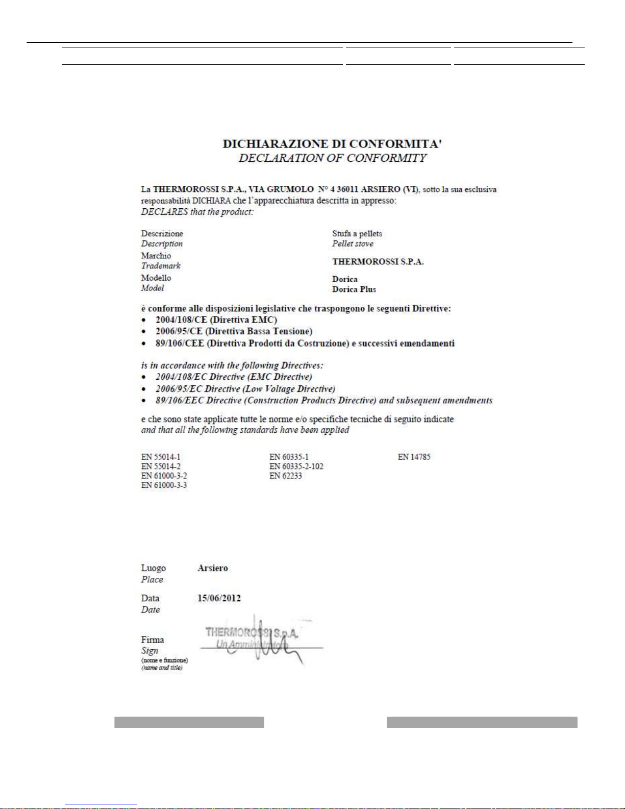
“EC” DECLARATION OF CONFORMITY

Page 6
manutenzione
1 - INTRODUCTION
1. 1 GENERAL GUIDELINES
This installation, use and maintenance guide is an integral and essential part of the product and must be kept by the user. Before
commencing with the installation, use and maintenance of the product, carefully read all the instructions contained in this booklet.
All local, national and European regulations regarding the installation and use of the appliance must be met. The Manufacturer
recommends carrying out all the maintenance operations described in this manual.
This appliance must only be used as intended by the manufacturer. Any other use is considered incorrect and therefore hazardous;
consequently, the user shall be totally liable for the product if used improperly. Installation, maintenance and repairs must be carried
out by professionally qualified personnel, professionally certified according to Decree no. 37 of 22 January 2008 and in compliance
with current regulations and in accordance with the instructions provided by the manufacturer of the appliance. In case of repairs
only original spare parts supplied by the manufacturer must be used. Incorrect installation or poor maintenance could injure or
damage people, animals or things; in this case the manufacturer shall be relieved of all responsibility. Before beginning any
cleaning or maintenance operation switch off the appliance, turn the switch installed at the back of the appliance to the OFF position
and disconnect the plug from the electrical power socket. The product must be installed in locations suitable for fire-fighting and
furnished with all the services (power and outlets) which the appliance requires for a correct and safe operation. Any repairs or
actions carried out on any systems, components or internal parts of the appliance, or on any of the accessories supplied with it, that
are not specifically authorised by Thermorossi S.p.A. will automatically void the warranty and the manufacturer's responsibility,
pursuant to D.P.R. 224 of 24/05/1988, art. 6/b. Keep this manual in a safe place that is easily accessible to all users: if the manual
is lost or deteriorated contact the manufacturer for a replacement copy. If the appliance is sold or transferred to another user ensure
that the guide is handed over with it. If this manual is lost and/or damaged it is mandatory to ask the manufacturer for a replacement
copy.
Thermorossi S.p.A. retains copyright on these service instructions. These instructions may not be reproduced or communicated to
third parties or used in any other way without the necessary authorisation.
1.2 SAFETY GUIDELINES
PERSONAL INJURY
This safety symbol identifies important messages throughout the manual. Read the information
marked by this symbol carefully as non-observance of this message can cause serious injury to
persons using the appliance.
DAMAGE TO PROPERTY
This safety symbol identifies messages or instructions that are fundamental for the appliance and
system to function well. To avoid serious damage to the appliance adhere strictly to these
instructions.
INFORMATION
This symbol indicates important instructions for good functioning of the appliance. If this information
is not correctly observed, the performance of the appliance will not be satisfactory.
NORMATIVE REFERENCES :
complies with the legislative provisions transposing the following Directives:
2004/108/CE (EMC Directive)
2006/95/CE (Low voltage directive)
89/106/CEE (Construction Products Directive) and subsequent amendments
and that all the standards and/or technical specifications listed below were applied
EN 55014-1 EN 55014-2 EN 61000-3-2 EN 61000-3-3 EN 60335-1 EN 60335-2-102 EN 62233 EN 14785
1.2.1. RECOMMENDATIONS
Before using the appliance, carefully read every section of this instruction manual as knowledge of the information
and the regulations contained in it are essential for a correct use of the appliance.
The entire operation concerning the connection of the electric panel must be carried out by expert personnel; no
responsibility will be accepted for damages, even to third parties, if the instructions for installation, use and
maintenance of the appliance are not followed scrupulously. Modifications made to the appliance by the user or on
his behalf, must be considered to be under his complete responsibility. The user is responsible for all the operations
required for the maintenance of the appliance before and during its use.
Page 7
manutenzione
1.2.2 GENERAL GUIDELINES
Caution: the appliance must be connected to a system provided with a PE conductor (in compliance with the
specifications of 73/23/EEC, 93/98/EEC, concerning low voltage equipment).
Before installing the appliance check the efficiency of the earth circuit of the power supply system.
Caution: the power supply line must have a section which is suitable for the power of the equipment. The cable section must in any
case be no less than 1.5 mm². The appliance requires powering with a voltage of 220-240 V and 50 Hz. Voltage variations greater
than 10% of the nominal value can cause irregular operation or damage the electrical device. Position the appliance so that the
electric power plug is easily accessible. Ensure that a suitable differential switch is installed upstream from the equipment.
Your appliance has obtained the CE marking and has been made to run for 1 hour to check that it functions correctly.
The product must not be used by children, by persons with physical or mental impairments, by persons who are not familiar with the
instructions for use and maintenance of the product (the instructions are found in this booklet).
CAUTION: Before each use make sure that the burner is clean and positioned correctly in its lodging, check that the ash pans are
clean and shut tight and check that the firebox door is locked.
WARNING: the door must always remain shut tight when the appliance is operating. It is strictly forbidden to open the door while
the appliance is in operation. While the appliance is in operation the smoke exhaust pipes and the appliance itself can reach
extremely high temperatures: do not touch them! Do not expose your body to hot air for long, do not overheat the room in which the
appliance is installed, as these actions could cause health problems. Do not expose plants or animals directly to the hot air flow as
this could have noxious effects on them. It is strictly forbidden to use any type of fuel (liquid, solid...) to light the appliance: the
appliance must light up automatically as designed and described in this installation, use and maintenance booklet; in this regard, it
is strictly prohibited to pour pellets (or other material) directly into the brazier. Do not place non-heat resistant or inflammable or
combustible objects in the vicinity of the appliance: keep them at a suitable distance. Do not place wet clothing to dry on the
appliance. When using a clothes horse, keep at a suitable distance. It is strictly prohibited to disconnect the appliance from the
electrical power mains.
Warning: do not wet the appliance and do not touch the electrical parts with wet hands. Never vacuum hot ash: this
could damage the vacuum device. All the cleaning operations described in this manual must be carried out when the
appliance is cold.
Caution! Warning for Swiss users
Refer to the local cantonal regulations imposed by the Fire Department (Mandatory signalling and safety distances )
and the Note concerning installation of heaters issued by the Association of Cantonal Fire Agencies (VKF - AEAI).
1.3 TRANSPORTATION AND STORAGE
TRANSPORTATION AND HANDLING
The appliance must always be in a vertical position when handled and exclusively by means of trolleys. Take special care to protect
the electric panel, the glass, and all the fragile parts from mechanical impact which could damage them and their correct
functioning.
STORAGE
The appliance must be stored in a humid-free environment and sheltered from the weather; do not place the appliance directly on
the floor. The Company denies all responsibility for damage caused to wood floors or floors made from any other material.
It is inadvisable to store the appliance for long periods of time.
Page 8
manutenzione
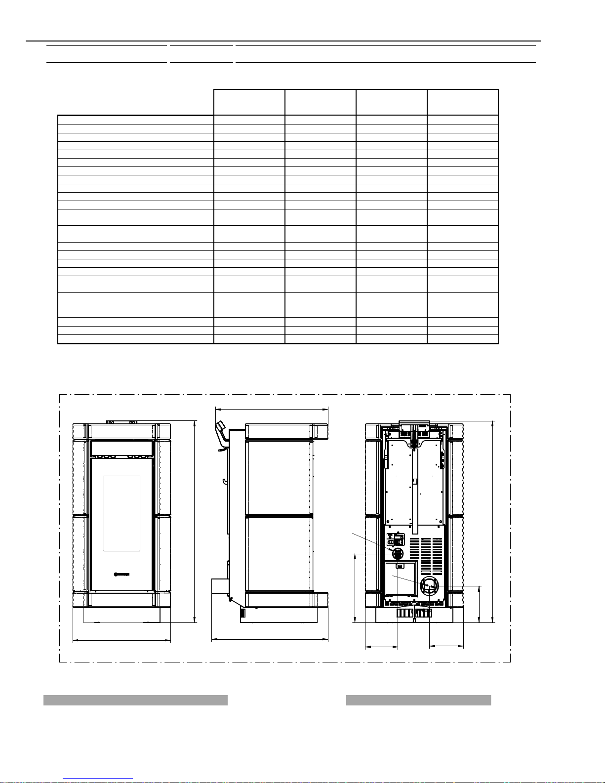
2 – TECHNICAL CHARACTERISTICS*
DORICA
METALCOLOR
DORICA
MAIOLICA
DORICA PLUS
METALCOLOR
DORICA PLUS
MAIOLICA
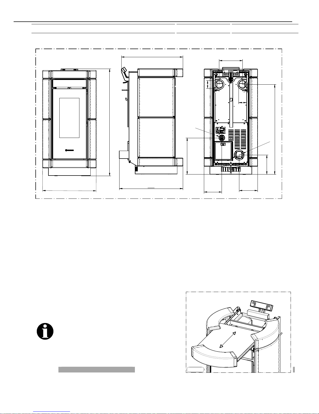
Height (mm) 1114 1114 1114 1114
Depth (mm) 665 665 665 665
Length (mm) 560 560 560 560
Weight (Kg) 132 142 132 142
Firebox power Min. / Max. (KW) 2.98 / 10.2 2.98 / 10.2 2.98 / 10.2 2.98 / 10.2
Rated power Min. / Max. (KW) 2.5 / 9.2 2.5 / 9.2 2.5 / 9.2 2.5 / 9.2
Min/max consumption (Kg/h) 0.70/2.3 0.70/2.3 0.70/2.3 0.70/2.3
Ø smoke exhaust pipe (mm) 80 80 80 80
Min. draught at rated power (Pa) 12 12 12 12
Min. draught at reduced power (Pa) 10 10 10 10
Tank capacity (Kg) approx. 19 approx. 19 approx. 15 approx. 15
Average smoke temperature at rated power
(°C)
180 180 180 180
Average smoke temperature at reduced power
(°C)
Not detected Not detected Not detected Not detected
Smoke flow at rated power (g/sec) 5.5 5.5 5.5 5.5
Smoke flow at reduced power (g/ sec) Not detected Not detected Not detected Not detected
Efficiency at rated power (%) 90.2 90.2 90.2 90.2
Efficiency at reduced power (%) 84.2 84.2 84.2 84.2
CO concentration in exhaust gas with 13% O2
at rated power (mg/M3)
188 188 188 188
CO concentration in exhaust gas with 13% O2
at rated power (mg/M3)
Not detected Not detected Not detected Not detected
Power supply voltage and frequency 220 V 50 HZ 220 V 50 HZ 220 V 50 HZ 220 V 50 HZ
Max electrical consumption 1.17A - 270W 1.17A - 270W 1.17A - 270W 1.17A - 270W
Min electrical consumption 0.34A - 70W 0.34A - 70W 0.34A - 70W 0.34A - 70W
Room heating capacity cubic metres 210** 210** 210** 210**
* All the data are based on the appliance fuelled with Austrian standard ÖNORM M 7135 type-approved pellets.
** It is important to take into consideration the fact that the heatable volume is greatly influenced by the insulation of the
house (energy class of the building) and by the position of the appliance in the planimetry of the house, therefore the
indicated values may vary, even significantly.
560
1114
665
644
202
O
8
0
193
1114
381
186
O
50
DORICA
Page 9
manutenzione
1114
644
665
5
6
0
202
193
O
8
0
381
186
O
50
937
245
80
O
80
O
DORICA PLUS
3 – GENERAL DESCRIPTION
3.1 OPERATING TECHNOLOGY
Your appliance has been built to fully satisfy all your heating and practical requirements. Top-grade components and functions
managed with microprocessor technology guarantee high reliability and optimal performance.
3.2 PELLETS
The appliance is fuelled by pellets, that is, cylinders of compressed sawdust; this allows you to fully enjoy the heat of the flame
without having to manually stoke the combustion.
The pellets have a 6 mm diameter and a maximum length of 15 mm. They have a maximum moisture content of 8%; thermal value
4000/4500 Kcal/Kg and density of 620-630 Kg/m³, less than 0.7% ash content.
It is strictly forbidden to use any pellet type other than that specified above. The use of fuel that does not comply with the
above specifications not only immediately invalidates the warranty for the appliance but can also create dangerous
situations. Do not use the appliance as an incinerator, at the risk of
voiding the warranty.
3.3 THE FEEDBOX
The feedbox is situated in the top part of the appliance. The
load capacity specified in the technical data can vary
according to the specific weight of the pellets.
Take special care when loading the tank as the screw
feeder at its base is in motion. Take care when topping up
with fuel as the loading area can get very hot.
Only pellets that comply with the specifications listed above
must be fed into the tank;
Figura 1
Page 10
manutenzione
Never insert foreign objects into the tank. To access the feedbox firstly remove the tank cover as illustrated in Figure
1.
Caution: it is very important to use the supplied glove when removing the cover as the ceramic can be extremely hot.
Attention: when loading the pellets into the tank take care not to drop any in the inner parts of the appliance, as this
could cause live flames inside the appliance. The manufacturer recommends emptying the tank and vacuuming the
screw feeder zone once a month and during the summer period. The appliance is designed to run on pellet fuel. Use
of other combustible materials in the tank and/or combustion chamber is strictly prohibited.
4 - INSTALLATION
4.1 POSITIONING OF THE APPLIANCE
Follow the general guidelines set out in paragraph 1.1 to the letter. Keep in mind that the flooring of the room in which
the appliance is to be installed must withstand the combined weight of the appliance and the pellets contained in the
tank.
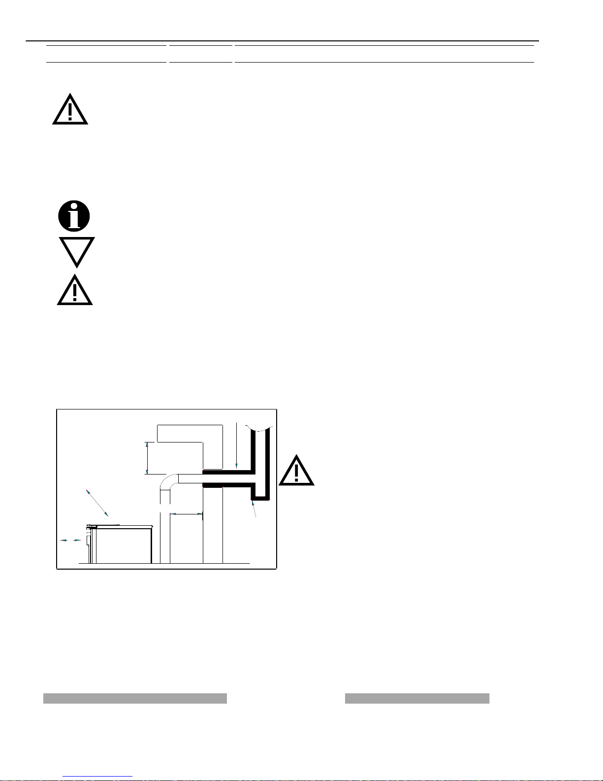
CAUTION: The appliance must be installed in a room with adequate ventilation. The appliance must be positioned at
a minimum safe distance from walls and furnishings. If inflammable items are positioned near the appliance
(matchboarding, furniture, curtains, wall hangings, sofas, etc...), this gap must be increased considerably. The
recommended minimum distances are illustrated in Figure 1. If the flooring is made of wood or any other combustible
material, it is recommended to install a fireproof floor protector plate between the appliance and the floor. Installation
in the vicinity of heat-sensitive materials is only permitted if suitable insulating and fireproof protection is placed
between the object and the appliance (ref. Uni 10683). Failure to observe this instruction will immediately invalidate
the warranty.
The installer must issue a certificate of conformity for the installation which includes the design plans and the
following documents:
a) Report containing the type of materials utilised.
b) Project as defined in Article 5 of Ministerial Decree n° 37 22 January 2008.
c) Drawing of the finished installation.
d) References to existing partial or previous declarations of conformity (e.g. electrical wiring).
e) Copy of the certificate of recognition of the professional technical qualifications.
These documents must, by law, be kept together with the
use and maintenance guide. The customer is responsible
for verifying, directly or indirectly, that the installation has
been carried out to perfection in accordance with relevant
regulations in force. Do not install the appliance in
unsuitable rooms such as bedrooms, bathrooms, garages
and/or lock-ups. It is forbidden to place the appliance in
environments with an explosive atmosphere.
ATTENTION , the stove is not simply a household
appliance: if the instructions set out in this booklet are not
followed and/or if installation of the appliance is not
executed perfectly and/or the provisions in force are not
strictly complied with dangerous conditions could arise for
both objects and persons.
LEGENDA KEY
Figura 1 Figure 1
ISOLANTE TERMICO HEAT INSULATING MATERIAL
T ispezionabile Inspectable Tee element
200/450 mm se materiale combustibile 200/450 mm if the material is combustible
200 mm se materiale combustibile
450 mm se materiale combustibile
ISOLANTE TERMICO
2
0
0
m
m
s
e
m
a
t
e
r
i
a
l
e
c
o
m
b
u
s
t
i
b
i
l
e
450 mm se materiale combustibile
T ispezionabile
Figura 1
Page 11
manutenzione
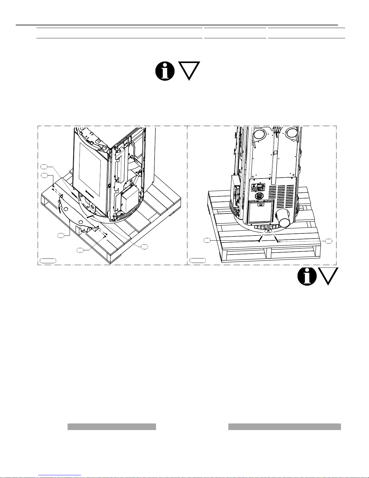
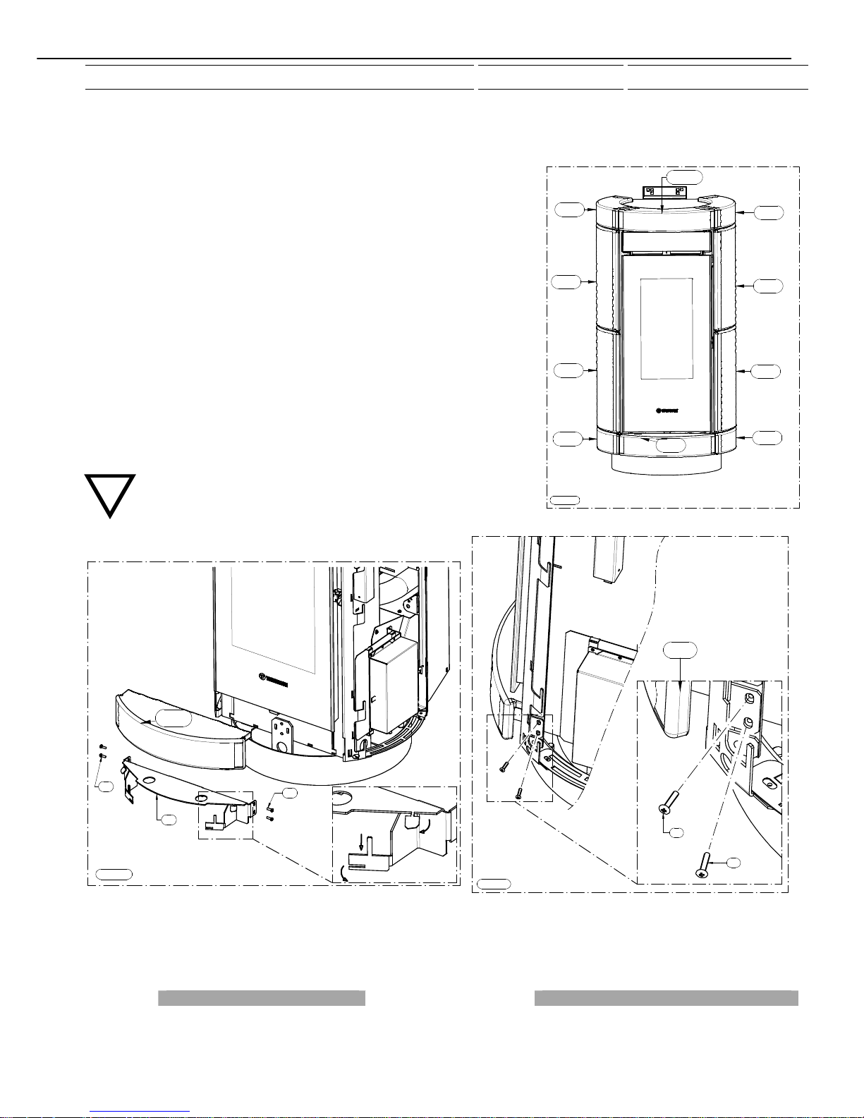
4.2 UNPACKING THE APPLIANCE
To unpack the appliance remove the packaging cover and sides, undo the 4 screws C that fix the appliance to the pallet. To remove
the 2 screws C indicated in Figure 1 firstly remove the bracket A by undoing the screws B. Next undo the last 2 screws C as
illustrated in Figure 2.
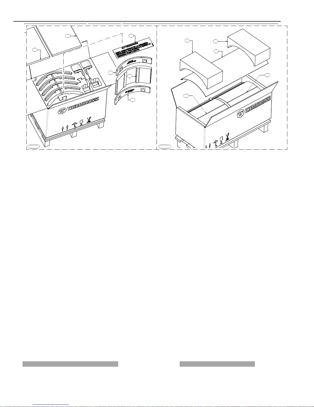
4.3 UNPACKING THE MAJOLICA CASING AND THE METALCOLOR CASING
To unpack the majolica casing follow the instructions illustrated in Figure 1; firstly open the box and remove the 2 polystyrene
elements A, then, with extreme care, remove each of the ceramic elements: once you have removed the ceramic indicated with the
letter C remove the polystyrene element D followed by the ceramic E.
To unpack the metalcolor casing follow the instructions illustrated in Figure 2; firstly open the box and remove the 2 polystyrene
elements E and remove the side panel F. Proceed to remove the polystyrene elements G which enclose 3 ceramics. Lastly remove
the second side panel F. Caution: the painted casings are delicate and must be handled with extreme care. Wear soft cotton
gloves. Clean with soft microfibre cloths for delicate surfaces such as lenses, glasses, monitors...
Figura 1
Figura 2
A
B
B
C
C
C
C
Page 12
manutenzione
Figura 1
E
C
B
A
A
D
Figura 2
E
E
F
G
G
Page 13
manutenzione
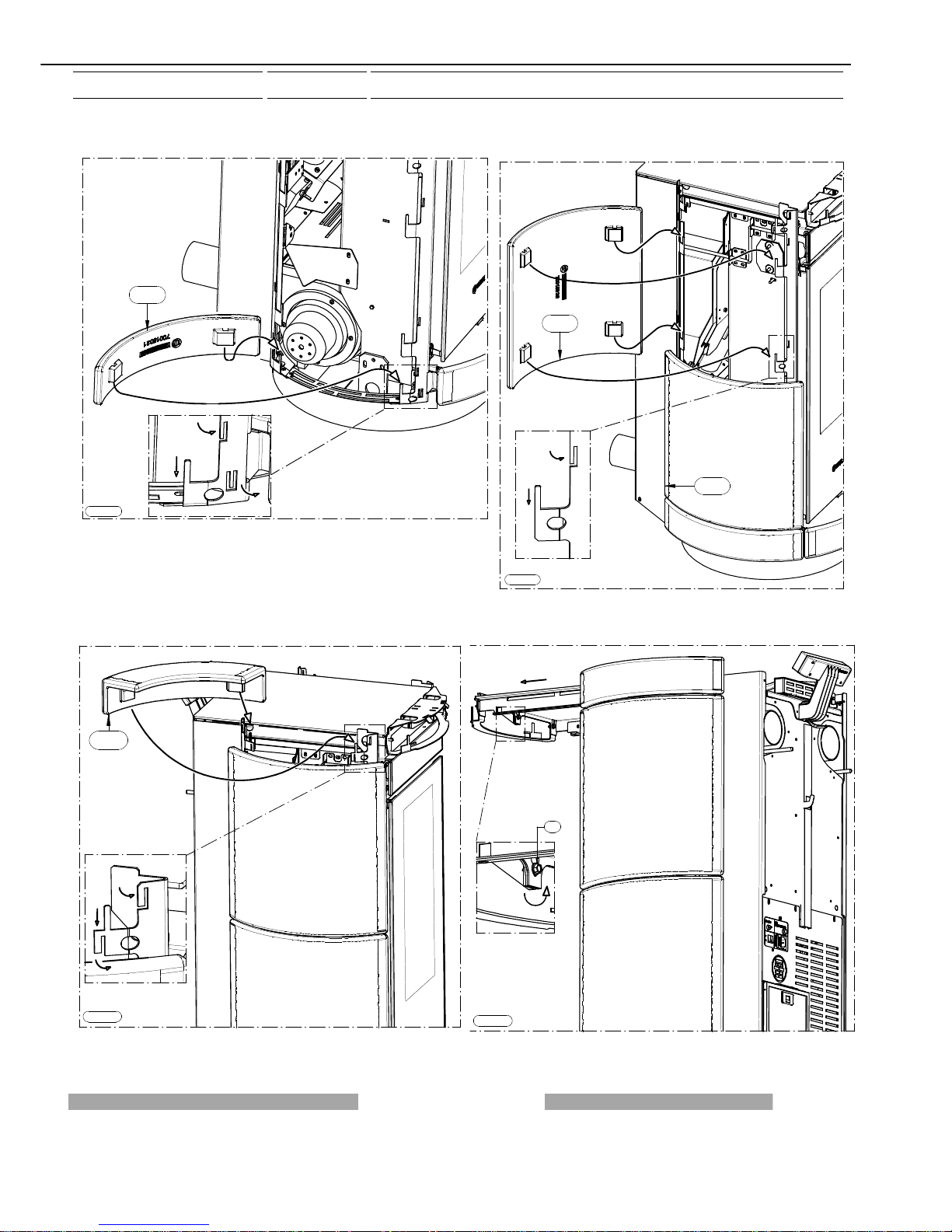
4.4 MOUNTING MAJOLICA CASING DORICA DORICA PLUS
Unpack the majolica casing and follow the instructions set out below:
- The majolica elements are numbered on the inner surface ( Figure 1).
- Firstly remove support B by acting on the screws A then insert the ceramic (1↑) in
the support; to make it integral with the support act on the indicated stops. Next fix
this assembled unit with the screws removed earlier (Figure 2 and Figure 3).
- Next mount the ceramic (2↑) as indicated in Figure 4, that is, by slightly bending
the stops until the ceramic is securely fastened.
- Then mount the ceramics (3↑) and (4↑) following the indications in Figure 5, that
is, by slightly bending the stops until the ceramic is securely fastened.
- Next mount the ceramic (5↑) following the indications in Figure 6, that is, by
slightly bending the tabs until the ceramic is securely fastened.
- Continue the procedure by mounting ceramics (6↑) (7↑) (8↑) and (9↑) using the
assembly logic described above (Figure 1).
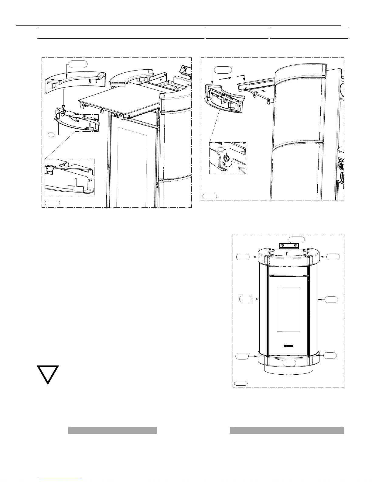
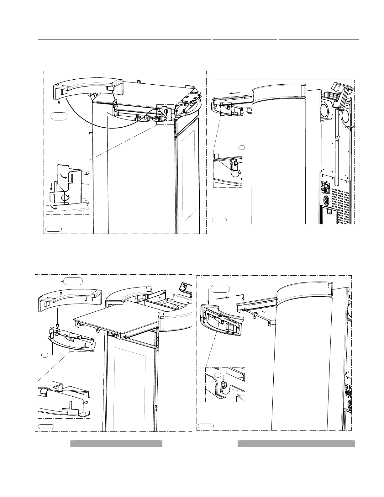
- Lastly, mount the ceramic (10↑):
remove the tank cover as indicated in Figure 7 and slightly loosen, by one turn, the
3 screws indicated with the letter C. Next remove support D by lifting it and pulling
it outwards. Fix the ceramic (10↑) as indicated in Figure 8 using the same
procedure described above (it is mandatory to fix the ceramic securely to the
support D with black high temperature silicone sealant). Next fix this assembled
unit by tightening the screws C (see Figure 9).
It is recommended to use pliers to bend the tabs.
CAUTION, IMPORTANT: carefully adjust the ceramics particularly around
the handle area and verify that the handle does not touch the ceramic
when opening or closing the door.
2 ↑
1 ↑
3 ↑
4 ↑
5 ↑
6 ↑
7 ↑
8 ↑
9 ↑
10 ↑
Figura 1
Figura 2
A
B
1 ↑
A
Figura 3
A
1 ↑
A
Page 14
manutenzione
Figura 4
2 ↑
Figura 7
C
Figura 6
5 ↑
Figura 5
3 ↑
4 ↑
Page 15
manutenzione
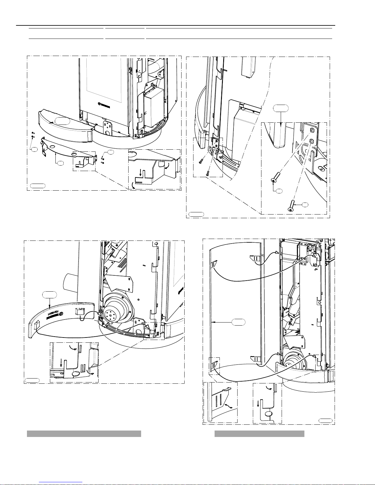
4.5 MOUNTING METALCOLOR CASING DORICA DORICA PLUS
Unpack the metalcolor casing and follow the instructions set out below:
- The majolica elements are numbered on the inner surface ( Figure 1).
- Firstly remove support B by acting on the screws A then insert the ceramic (1↑)
in the support; to make it integral with the support act on the indicated stops. Next
fix this assembled unit with the screws removed earlier (Figure 2 and Figure 3).
- Next mount the ceramic (2↑) as indicated in Figure 4, that is, by slightly bending
the stops until the ceramic is securely fastened.
- Then mount the metalcolor side panel (3↑) following the indications in Figure 5,
that is, by slightly bending the stops until the metalcolor side panel is securely
fastened.
- Next mount the ceramic (5↑) following the indications in Figure 6, that is, by
slightly bending the tabs until the ceramic is securely fastened.
- Continue the procedure by mounting ceramics (6↑), the metal side panel (7↑)
and the ceramic (9↑) (Figure 1).
- Lastly, mount the ceramic (10↑):
remove the tank cover as indicated in Figure 7 and slightly loosen, by one turn,
the 3 screws indicated with the letter C. Next remove support D, fix the ceramic
(10↑) as indicated in Figure 8 using the same procedure described above (it is
mandatory to fix the ceramic securely to the support D with black high
temperature silicone sealant). Next fix this assembled unit by tightening the
screws C (see Figure 9). It is recommended to use pliers to bend the tabs.
CAUTION, IMPORTANT: carefully adjust the ceramics particularly
around the handle area and verify that the handle does not touch the
ceramic when opening or closing the door.
2 ↑
1 ↑
3 ↑
5 ↑
6 ↑
7 ↑
9 ↑
10 ↑
Figura 1
Figura 9
C
10 ↑
Figura 8
D
10 ↑
Page 16
manutenzione
Figura 2
A
B
1 ↑
A
Figura 3
A
1 ↑
A
Figura 4
2 ↑
Figura 5
3 ↑
Page 17
manutenzione
Figura 8
D
10 ↑
Figura 9
C
10 ↑
Figura 6
5 ↑
Figura 7
C
 Loading...