

THERMOROSSI DORICA METALCOLOR, DORICA MAIOLICA, DORICA PLUS METALCOLOR, DORICA PLUS MAIOLICA Installation, Use And Maintenance Manual
Page 1

Page 2

Page 2
manutenzione
INDEX
“EC” DECLARATION OF CONFORMITY................................................................................................. 0
1 - INTRODUCTION .................................................................................................................................. 0
1. 1 GENERAL GUIDELINES .................................................................................................................................0
1.2 SAFETY GUIDELINES .....................................................................................................................................0
1.2.1. RECOMMENDATIONS............................................................................................................................................................0
1.2.2 GENERAL GUIDELINES...........................................................................................................................................................0
1.3 TRANSPORTATION AND STORAGE..............................................................................................................0
2 – TECHNICAL CHARACTERISTICS*.................................................................................................... 0
3 – GENERAL DESCRIPTION.................................................................................................................. 0
3.1 OPERATING TECHNOLOGY...........................................................................................................................0
3.2 PELLETS...........................................................................................................................................................0
3.3 THE FEEDBOX.................................................................................................................................................0
4 - INSTALLATION ................................................................................................................................... 0
4.1 POSITIONING OF THE APPLIANCE...............................................................................................................0
4.2 UNPACKING THE APPLIANCE ......................................................................................................................0
4.3 UNPACKING THE MAJOLICA CASING AND THE METALCOLOR CASING................................................. 0
4.4 MOUNTING MAJOLICA CASING DORICA DORICA PLUS ...........................................................................0
4.5 MOUNTING METALCOLOR CASING DORICA DORICA PLUS .....................................................................0
4.6 CONNECTING THE APPLIANCE TO THE FLUE OUTLET.............................................................................0
4.7 HANDLE............................................................................................................................................................0
5 – DESCRIPTIONS OF CONTROLS ....................................................................................................... 0
5.1 DESCRIPTION OF CONTROL PANEL AND REAR PANEL ...........................................................................0
5.1 DESCRIPTION OF THE CONTROL PANEL................................................................................................................................0
5.1.2 APPLIANCE REAR PANEL.......................................................................................................................................................0
5.2 DAY AND TIME SETTING................................................................................................................................0
5.3 ON/OFF PROGRAMMING...............................................................................................................................0
5.3.1 ON-OFF PROGRAMMING DISPLAY........................................................................................................................................0
5.4 OPERATING LEVEL SETTING ........................................................................................................................0
6 – USE OF THE APPLIANCE.................................................................................................................. 0
6.1 SWITCHING ON THE APPLIANCE..................................................................................................................0
6.2 ADJUSTING COMBUSTION AND VENTILATION...........................................................................................0
6.3 INFRARED REMOTE CONTROL.....................................................................................................................0
6.4 OPERATION OF THE WHITE HANDHELD RADIO CONTROL THERMOCOMFORT (OPTIONAL) ............. 0
6.4.1 INDICATORS OF THE HANDHELD RADIO CONTROL............................................................................................................0
6.4.3 CARE AND MAINTENANCE OF THE RADIO CONTROL.........................................................................................................0
6.5 FILTER..............................................................................................................................................................0
6.6 CHANNELLING (DORICA PLUS ONLY)..........................................................................................................0
7 - ADDITIONAL ROOM TEMPERATURE THERMOSTAT (not supplied).............................................. 0
ADDITIONAL CHRONOTHERMOSTAT - MODEM (not supplied ).......................................................... 0
7.1 OPERATING WITH THE ADDITIONAL ROOM TEMPERATURE THERMOSTAT (not supplied) .................. 0
7.2 OPERATING WITH THE ADDITIONAL CHRONOTHERMOSTAT (not supplied)........................................... 0
Page 3

Page 3
manutenzione
8 - CLEANING AND MAINTENANCE........................................................................................................0
8.1 FOREWORD.....................................................................................................................................................0
8.2 CLEANING AND MAINTAINING THE APPLIANCE......................................................................................... 0
8.3 CHARGING THE BATTERY OF THE WHITE THERMOCOMFORT HANDHELD RADIO CONTROL (optional)
.........................................................................................................................................................................0
8.4 BATTERY REPLACEMENT FOR INFRARED REMOTE CONTROL.............................................................. 0
8.5 REPLACING THE BUFFER BATTERY OF THE CONTROL PANEL ..............................................................0
9.1 FOREWORD.....................................................................................................................................................0
9.2 ROOM VENTILATION ......................................................................................................................................0
9.2.2 VENTILATION OF THE ADJACENT ROOMS........................................................................................................................... 0
9.2.1 SINGLE OR MULTIPLE VENTILATION DUCTING................................................................................................................... 0
9.3 SMOKE OUTLET.............................................................................................................................................. 0
9.3.1 CHIMNEY TYPES..................................................................................................................................................................... 0
9.3.2 FLUE OUTLET / FLUE SYSTEM COMPONENTS................................................................................................................... 0
10 – ALARMS............................................................................................................................................0
11 - ELECTRICAL WIRING .......................................................................................................................0
12 - INFORMATION FOR THE SKILLED TECHNICIAN............................................................................ 0
12.1 MAIN COMPONENTS AND THEIR OPERATION ......................................................................................... 0
12.2 REQUIREMENTS NECESSARY FOR CORRECT INSTALLATION AND OPERATION .............................. 0
12.3 TROUBLESHOOTING CAUSE-SOLUTION................................................................................................... 0
13 - SPARE PARTS...................................................................................................................................0
13.1 SPARE PARTS DORICA PAG. 1/5 ...............................................................................................................0
13.2 SPARE PARTS DORICA PAG. 2/5 ...............................................................................................................0
13.3 SPARE PARTS DORICA PAG. 3/5 ...............................................................................................................0
13.5 SPARE PARTS DORICA PAG. 5/5 ...............................................................................................................0
13.6 SPARE PARTS DORICA PLUS PAG. 1/5...................................................................................................... 0
13.7 SPARE PARTS DORICA PLUS PAG. 2/5...................................................................................................... 0
13.8 SPARE PARTS DORICA PLUS PAG. 3/5...................................................................................................... 0
13.9 SPARE PARTS DORICA PLUS PAG. 4/5...................................................................................................... 0
13.10 SPARE PARTS DORICA PLUS PAG. 5/5.................................................................................................... 0
Page 4
Page 4
manutenzione
Page 5
Page 5
manutenzione
“EC” DECLARATION OF CONFORMITY
Page 6

Page 6
manutenzione
1 - INTRODUCTION
1. 1 GENERAL GUIDELINES
This installation, use and maintenance guide is an integral and essential part of the product and must be kept by the user. Before
commencing with the installation, use and maintenance of the product, carefully read all the instructions contained in this booklet.
All local, national and European regulations regarding the installation and use of the appliance must be met. The Manufacturer
recommends carrying out all the maintenance operations described in this manual.
This appliance must only be used as intended by the manufacturer. Any other use is considered incorrect and therefore hazardous;
consequently, the user shall be totally liable for the product if used improperly. Installation, maintenance and repairs must be carried
out by professionally qualified personnel, professionally certified according to Decree no. 37 of 22 January 2008 and in compliance
with current regulations and in accordance with the instructions provided by the manufacturer of the appliance. In case of repairs
only original spare parts supplied by the manufacturer must be used. Incorrect installation or poor maintenance could injure or
damage people, animals or things; in this case the manufacturer shall be relieved of all responsibility. Before beginning any
cleaning or maintenance operation switch off the appliance, turn the switch installed at the back of the appliance to the OFF position
and disconnect the plug from the electrical power socket. The product must be installed in locations suitable for fire-fighting and
furnished with all the services (power and outlets) which the appliance requires for a correct and safe operation. Any repairs or
actions carried out on any systems, components or internal parts of the appliance, or on any of the accessories supplied with it, that
are not specifically authorised by Thermorossi S.p.A. will automatically void the warranty and the manufacturer's responsibility,
pursuant to D.P.R. 224 of 24/05/1988, art. 6/b. Keep this manual in a safe place that is easily accessible to all users: if the manual
is lost or deteriorated contact the manufacturer for a replacement copy. If the appliance is sold or transferred to another user ensure
that the guide is handed over with it. If this manual is lost and/or damaged it is mandatory to ask the manufacturer for a replacement
copy.
Thermorossi S.p.A. retains copyright on these service instructions. These instructions may not be reproduced or communicated to
third parties or used in any other way without the necessary authorisation.
1.2 SAFETY GUIDELINES
PERSONAL INJURY
This safety symbol identifies important messages throughout the manual. Read the information
marked by this symbol carefully as non-observance of this message can cause serious injury to
persons using the appliance.
DAMAGE TO PROPERTY
This safety symbol identifies messages or instructions that are fundamental for the appliance and
system to function well. To avoid serious damage to the appliance adhere strictly to these
instructions.
INFORMATION
This symbol indicates important instructions for good functioning of the appliance. If this information
is not correctly observed, the performance of the appliance will not be satisfactory.
NORMATIVE REFERENCES :
complies with the legislative provisions transposing the following Directives:
2004/108/CE (EMC Directive)
2006/95/CE (Low voltage directive)
89/106/CEE (Construction Products Directive) and subsequent amendments
and that all the standards and/or technical specifications listed below were applied
EN 55014-1 EN 55014-2 EN 61000-3-2 EN 61000-3-3 EN 60335-1 EN 60335-2-102 EN 62233 EN 14785
1.2.1. RECOMMENDATIONS
Before using the appliance, carefully read every section of this instruction manual as knowledge of the information
and the regulations contained in it are essential for a correct use of the appliance.
The entire operation concerning the connection of the electric panel must be carried out by expert personnel; no
responsibility will be accepted for damages, even to third parties, if the instructions for installation, use and
maintenance of the appliance are not followed scrupulously. Modifications made to the appliance by the user or on
his behalf, must be considered to be under his complete responsibility. The user is responsible for all the operations
required for the maintenance of the appliance before and during its use.
Page 7
Page 7
manutenzione
1.2.2 GENERAL GUIDELINES
Caution: the appliance must be connected to a system provided with a PE conductor (in compliance with the
specifications of 73/23/EEC, 93/98/EEC, concerning low voltage equipment).
Before installing the appliance check the efficiency of the earth circuit of the power supply system.
Caution: the power supply line must have a section which is suitable for the power of the equipment. The cable section must in any
case be no less than 1.5 mm². The appliance requires powering with a voltage of 220-240 V and 50 Hz. Voltage variations greater
than 10% of the nominal value can cause irregular operation or damage the electrical device. Position the appliance so that the
electric power plug is easily accessible. Ensure that a suitable differential switch is installed upstream from the equipment.
Your appliance has obtained the CE marking and has been made to run for 1 hour to check that it functions correctly.
The product must not be used by children, by persons with physical or mental impairments, by persons who are not familiar with the
instructions for use and maintenance of the product (the instructions are found in this booklet).
CAUTION: Before each use make sure that the burner is clean and positioned correctly in its lodging, check that the ash pans are
clean and shut tight and check that the firebox door is locked.
WARNING: the door must always remain shut tight when the appliance is operating. It is strictly forbidden to open the door while
the appliance is in operation. While the appliance is in operation the smoke exhaust pipes and the appliance itself can reach
extremely high temperatures: do not touch them! Do not expose your body to hot air for long, do not overheat the room in which the
appliance is installed, as these actions could cause health problems. Do not expose plants or animals directly to the hot air flow as
this could have noxious effects on them. It is strictly forbidden to use any type of fuel (liquid, solid...) to light the appliance: the
appliance must light up automatically as designed and described in this installation, use and maintenance booklet; in this regard, it
is strictly prohibited to pour pellets (or other material) directly into the brazier. Do not place non-heat resistant or inflammable or
combustible objects in the vicinity of the appliance: keep them at a suitable distance. Do not place wet clothing to dry on the
appliance. When using a clothes horse, keep at a suitable distance. It is strictly prohibited to disconnect the appliance from the
electrical power mains.
Warning: do not wet the appliance and do not touch the electrical parts with wet hands. Never vacuum hot ash: this
could damage the vacuum device. All the cleaning operations described in this manual must be carried out when the
appliance is cold.
Caution! Warning for Swiss users
Refer to the local cantonal regulations imposed by the Fire Department (Mandatory signalling and safety distances )
and the Note concerning installation of heaters issued by the Association of Cantonal Fire Agencies (VKF - AEAI).
1.3 TRANSPORTATION AND STORAGE
TRANSPORTATION AND HANDLING
The appliance must always be in a vertical position when handled and exclusively by means of trolleys. Take special care to protect
the electric panel, the glass, and all the fragile parts from mechanical impact which could damage them and their correct
functioning.
STORAGE
The appliance must be stored in a humid-free environment and sheltered from the weather; do not place the appliance directly on
the floor. The Company denies all responsibility for damage caused to wood floors or floors made from any other material.
It is inadvisable to store the appliance for long periods of time.
Page 8
Page 8
manutenzione
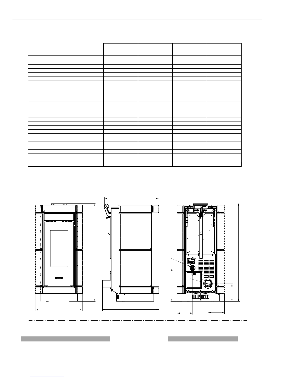
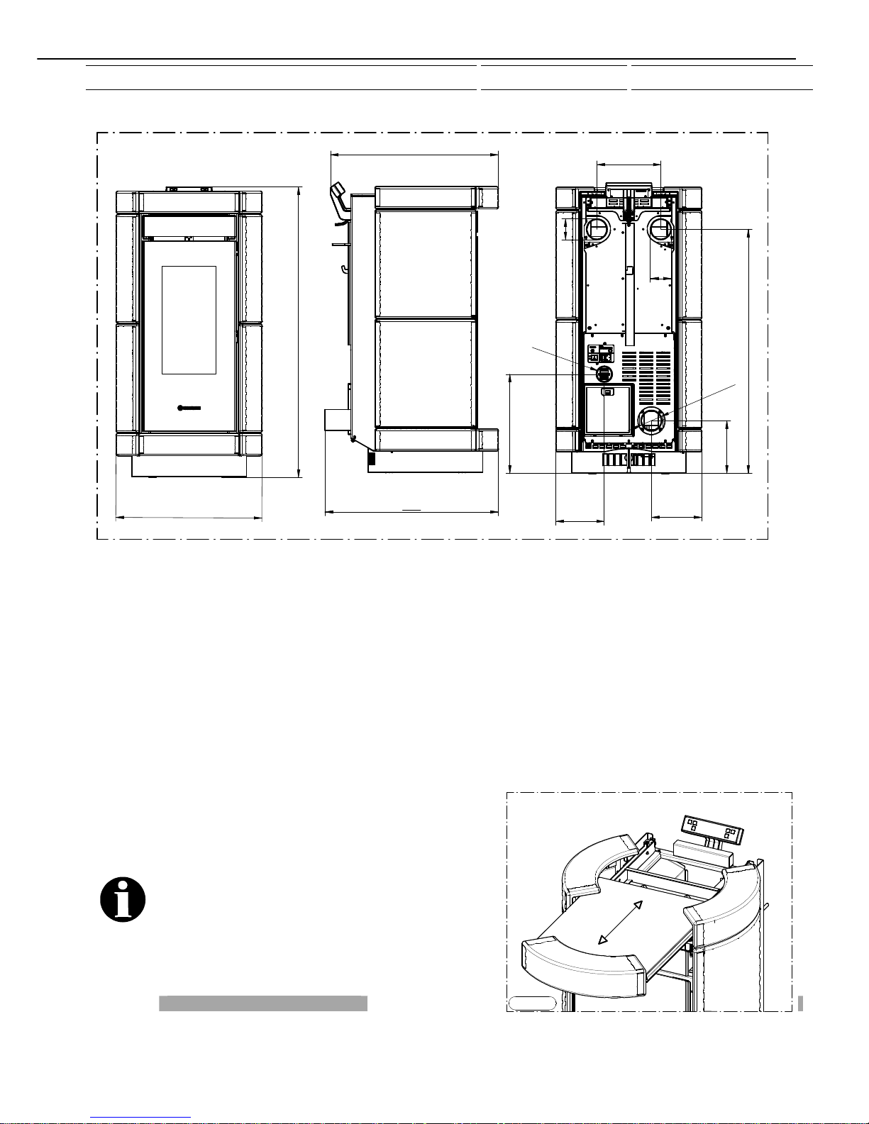
2 – TECHNICAL CHARACTERISTICS*
DORICA
METALCOLOR
DORICA
MAIOLICA
DORICA PLUS
METALCOLOR
DORICA PLUS
MAIOLICA
Height (mm) 1114 1114 1114 1114
Depth (mm) 665 665 665 665
Length (mm) 560 560 560 560
Weight (Kg) 132 142 132 142
Firebox power Min. / Max. (KW) 2.98 / 10.2 2.98 / 10.2 2.98 / 10.2 2.98 / 10.2
Rated power Min. / Max. (KW) 2.5 / 9.2 2.5 / 9.2 2.5 / 9.2 2.5 / 9.2
Min/max consumption (Kg/h) 0.70/2.3 0.70/2.3 0.70/2.3 0.70/2.3
Ø smoke exhaust pipe (mm) 80 80 80 80
Min. draught at rated power (Pa) 12 12 12 12
Min. draught at reduced power (Pa) 10 10 10 10
Tank capacity (Kg) approx. 19 approx. 19 approx. 15 approx. 15
Average smoke temperature at rated power
(°C)
180 180 180 180
Average smoke temperature at reduced power
(°C)
Not detected Not detected Not detected Not detected
Smoke flow at rated power (g/sec) 5.5 5.5 5.5 5.5
Smoke flow at reduced power (g/ sec) Not detected Not detected Not detected Not detected
Efficiency at rated power (%) 90.2 90.2 90.2 90.2
Efficiency at reduced power (%) 84.2 84.2 84.2 84.2
CO concentration in exhaust gas with 13% O2
at rated power (mg/M3)
188 188 188 188
CO concentration in exhaust gas with 13% O2
at rated power (mg/M3)
Not detected Not detected Not detected Not detected
Power supply voltage and frequency 220 V 50 HZ 220 V 50 HZ 220 V 50 HZ 220 V 50 HZ
Max electrical consumption 1.17A - 270W 1.17A - 270W 1.17A - 270W 1.17A - 270W
Min electrical consumption 0.34A - 70W 0.34A - 70W 0.34A - 70W 0.34A - 70W
Room heating capacity cubic metres 210** 210** 210** 210**
* All the data are based on the appliance fuelled with Austrian standard ÖNORM M 7135 type-approved pellets.
** It is important to take into consideration the fact that the heatable volume is greatly influenced by the insulation of the
house (energy class of the building) and by the position of the appliance in the planimetry of the house, therefore the
indicated values may vary, even significantly.
560
1114
665
644
202
O
8
0
193
1114
381
186
O
50
DORICA
Page 9
Page 9
manutenzione
1114
644
665
5
6
0
202
193
O
8
0
381
186
O
50
937
245
80
O
80
O
DORICA PLUS
3 – GENERAL DESCRIPTION
3.1 OPERATING TECHNOLOGY
Your appliance has been built to fully satisfy all your heating and practical requirements. Top-grade components and functions
managed with microprocessor technology guarantee high reliability and optimal performance.
3.2 PELLETS
The appliance is fuelled by pellets, that is, cylinders of compressed sawdust; this allows you to fully enjoy the heat of the flame
without having to manually stoke the combustion.
The pellets have a 6 mm diameter and a maximum length of 15 mm. They have a maximum moisture content of 8%; thermal value
4000/4500 Kcal/Kg and density of 620-630 Kg/m³, less than 0.7% ash content.
It is strictly forbidden to use any pellet type other than that specified above. The use of fuel that does not comply with the
above specifications not only immediately invalidates the warranty for the appliance but can also create dangerous
situations. Do not use the appliance as an incinerator, at the risk of
voiding the warranty.
3.3 THE FEEDBOX
The feedbox is situated in the top part of the appliance. The
load capacity specified in the technical data can vary
according to the specific weight of the pellets.
Take special care when loading the tank as the screw
feeder at its base is in motion. Take care when topping up
with fuel as the loading area can get very hot.
Only pellets that comply with the specifications listed above
must be fed into the tank;
Figura 1
Page 10
Page 10
manutenzione
Never insert foreign objects into the tank. To access the feedbox firstly remove the tank cover as illustrated in Figure
1.
Caution: it is very important to use the supplied glove when removing the cover as the ceramic can be extremely hot.
Attention: when loading the pellets into the tank take care not to drop any in the inner parts of the appliance, as this
could cause live flames inside the appliance. The manufacturer recommends emptying the tank and vacuuming the
screw feeder zone once a month and during the summer period. The appliance is designed to run on pellet fuel. Use
of other combustible materials in the tank and/or combustion chamber is strictly prohibited.
4 - INSTALLATION
4.1 POSITIONING OF THE APPLIANCE
Follow the general guidelines set out in paragraph 1.1 to the letter. Keep in mind that the flooring of the room in which
the appliance is to be installed must withstand the combined weight of the appliance and the pellets contained in the
tank.
CAUTION: The appliance must be installed in a room with adequate ventilation. The appliance must be positioned at
a minimum safe distance from walls and furnishings. If inflammable items are positioned near the appliance
(matchboarding, furniture, curtains, wall hangings, sofas, etc...), this gap must be increased considerably. The
recommended minimum distances are illustrated in Figure 1. If the flooring is made of wood or any other combustible
material, it is recommended to install a fireproof floor protector plate between the appliance and the floor. Installation
in the vicinity of heat-sensitive materials is only permitted if suitable insulating and fireproof protection is placed
between the object and the appliance (ref. Uni 10683). Failure to observe this instruction will immediately invalidate
the warranty.
The installer must issue a certificate of conformity for the installation which includes the design plans and the
following documents:
a) Report containing the type of materials utilised.
b) Project as defined in Article 5 of Ministerial Decree n° 37 22 January 2008.
c) Drawing of the finished installation.
d) References to existing partial or previous declarations of conformity (e.g. electrical wiring).
e) Copy of the certificate of recognition of the professional technical qualifications.
These documents must, by law, be kept together with the
use and maintenance guide. The customer is responsible
for verifying, directly or indirectly, that the installation has
been carried out to perfection in accordance with relevant
regulations in force. Do not install the appliance in
unsuitable rooms such as bedrooms, bathrooms, garages
and/or lock-ups. It is forbidden to place the appliance in
environments with an explosive atmosphere.
ATTENTION , the stove is not simply a household
appliance: if the instructions set out in this booklet are not
followed and/or if installation of the appliance is not
executed perfectly and/or the provisions in force are not
strictly complied with dangerous conditions could arise for
both objects and persons.
LEGENDA KEY
Figura 1 Figure 1
ISOLANTE TERMICO HEAT INSULATING MATERIAL
T ispezionabile Inspectable Tee element
200/450 mm se materiale combustibile 200/450 mm if the material is combustible
200 mm se materiale combustibile
450 mm se materiale combustibile
ISOLANTE TERMICO
2
0
0
m
m
s
e
m
a
t
e
r
i
a
l
e
c
o
m
b
u
s
t
i
b
i
l
e
450 mm se materiale combustibile
T ispezionabile
Figura 1
Page 11
Page 11
manutenzione
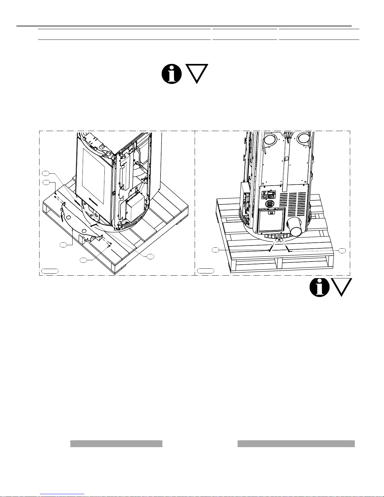
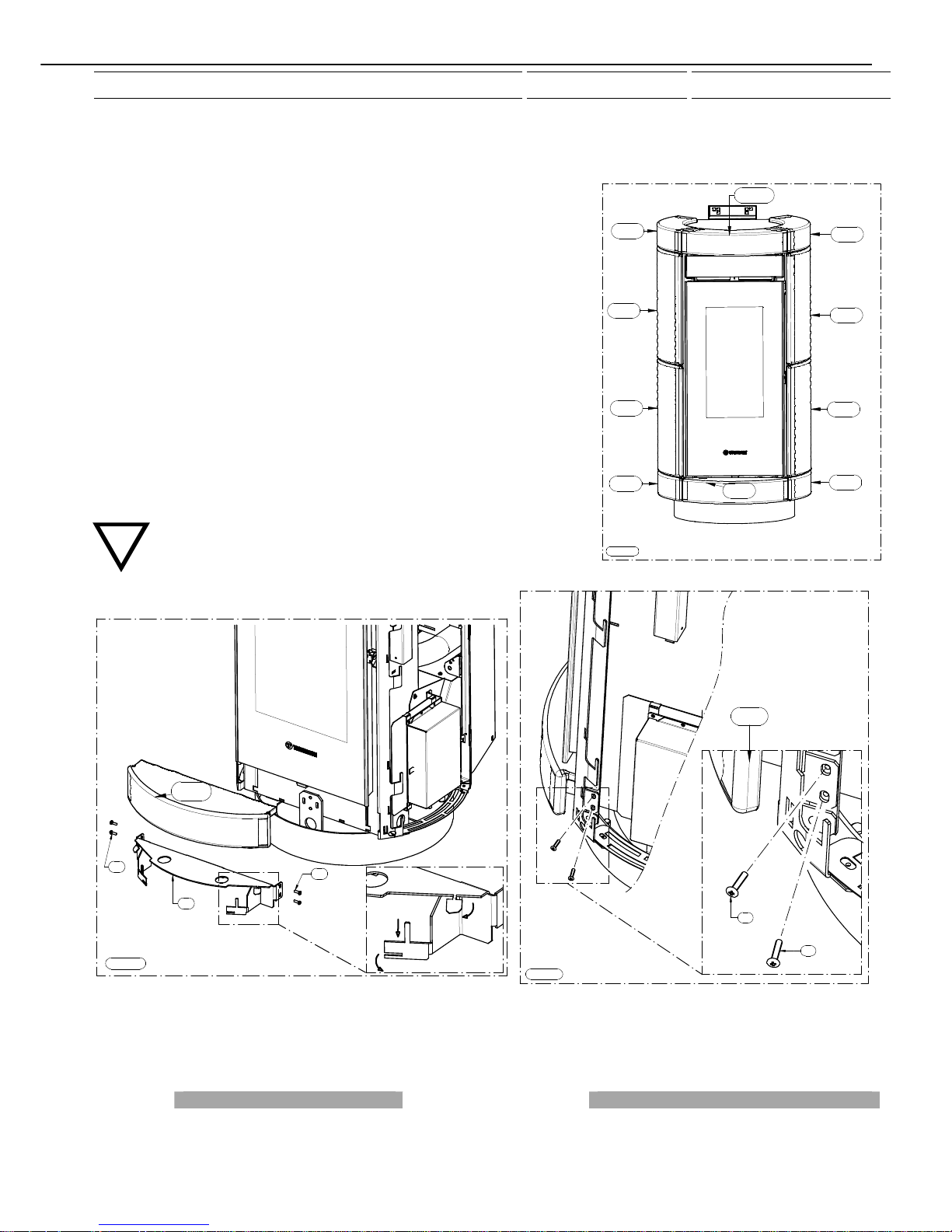
4.2 UNPACKING THE APPLIANCE
To unpack the appliance remove the packaging cover and sides, undo the 4 screws C that fix the appliance to the pallet. To remove
the 2 screws C indicated in Figure 1 firstly remove the bracket A by undoing the screws B. Next undo the last 2 screws C as
illustrated in Figure 2.
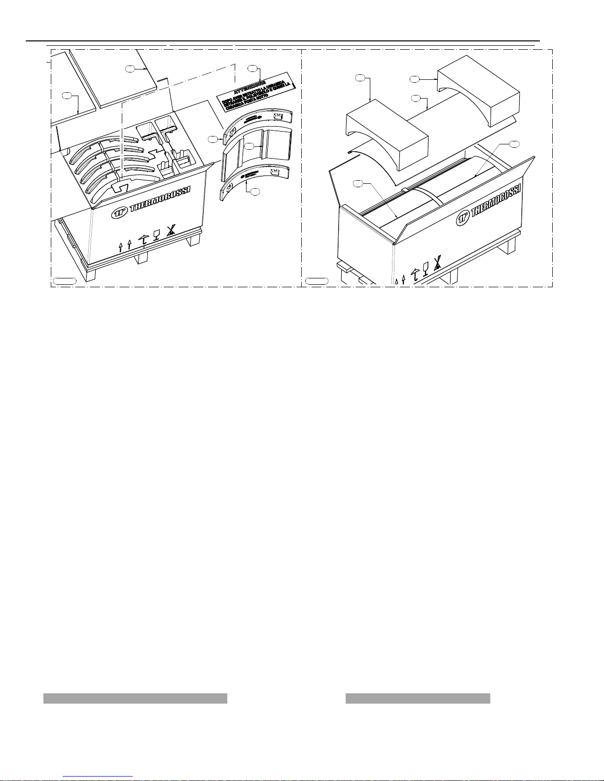
4.3 UNPACKING THE MAJOLICA CASING AND THE METALCOLOR CASING
To unpack the majolica casing follow the instructions illustrated in Figure 1; firstly open the box and remove the 2 polystyrene
elements A, then, with extreme care, remove each of the ceramic elements: once you have removed the ceramic indicated with the
letter C remove the polystyrene element D followed by the ceramic E.
To unpack the metalcolor casing follow the instructions illustrated in Figure 2; firstly open the box and remove the 2 polystyrene
elements E and remove the side panel F. Proceed to remove the polystyrene elements G which enclose 3 ceramics. Lastly remove
the second side panel F. Caution: the painted casings are delicate and must be handled with extreme care. Wear soft cotton
gloves. Clean with soft microfibre cloths for delicate surfaces such as lenses, glasses, monitors...
Figura 1
Figura 2
A
B
B
C
C
C
C
Page 12
Page 12
manutenzione
Figura 1
E
C
B
A
A
D
Figura 2
E
E
F
G
G
Page 13
Page 13
manutenzione
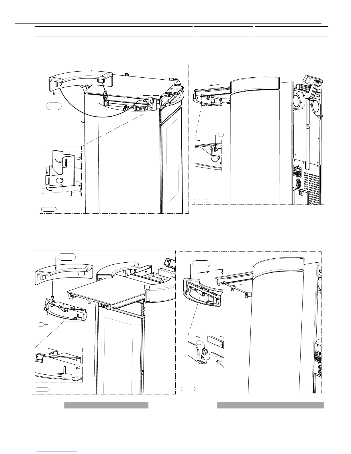
4.4 MOUNTING MAJOLICA CASING DORICA DORICA PLUS
Unpack the majolica casing and follow the instructions set out below:
- The majolica elements are numbered on the inner surface ( Figure 1).
- Firstly remove support B by acting on the screws A then insert the ceramic (1↑) in
the support; to make it integral with the support act on the indicated stops. Next fix
this assembled unit with the screws removed earlier (Figure 2 and Figure 3).
- Next mount the ceramic (2↑) as indicated in Figure 4, that is, by slightly bending
the stops until the ceramic is securely fastened.
- Then mount the ceramics (3↑) and (4↑) following the indications in Figure 5, that
is, by slightly bending the stops until the ceramic is securely fastened.
- Next mount the ceramic (5↑) following the indications in Figure 6, that is, by
slightly bending the tabs until the ceramic is securely fastened.
- Continue the procedure by mounting ceramics (6↑) (7↑) (8↑) and (9↑) using the
assembly logic described above (Figure 1).
- Lastly, mount the ceramic (10↑):
remove the tank cover as indicated in Figure 7 and slightly loosen, by one turn, the
3 screws indicated with the letter C. Next remove support D by lifting it and pulling
it outwards. Fix the ceramic (10↑) as indicated in Figure 8 using the same
procedure described above (it is mandatory to fix the ceramic securely to the
support D with black high temperature silicone sealant). Next fix this assembled
unit by tightening the screws C (see Figure 9).
It is recommended to use pliers to bend the tabs.
CAUTION, IMPORTANT: carefully adjust the ceramics particularly around
the handle area and verify that the handle does not touch the ceramic
when opening or closing the door.
2 ↑
1 ↑
3 ↑
4 ↑
5 ↑
6 ↑
7 ↑
8 ↑
9 ↑
10 ↑
Figura 1
Figura 2
A
B
1 ↑
A
Figura 3
A
1 ↑
A
Page 14
Page 14
manutenzione
Figura 4
2 ↑
Figura 7
C
Figura 6
5 ↑
Figura 5
3 ↑
4 ↑
Page 15
Page 15
manutenzione
4.5 MOUNTING METALCOLOR CASING DORICA DORICA PLUS
Unpack the metalcolor casing and follow the instructions set out below:
- The majolica elements are numbered on the inner surface ( Figure 1).
- Firstly remove support B by acting on the screws A then insert the ceramic (1↑)
in the support; to make it integral with the support act on the indicated stops. Next
fix this assembled unit with the screws removed earlier (Figure 2 and Figure 3).
- Next mount the ceramic (2↑) as indicated in Figure 4, that is, by slightly bending
the stops until the ceramic is securely fastened.
- Then mount the metalcolor side panel (3↑) following the indications in Figure 5,
that is, by slightly bending the stops until the metalcolor side panel is securely
fastened.
- Next mount the ceramic (5↑) following the indications in Figure 6, that is, by
slightly bending the tabs until the ceramic is securely fastened.
- Continue the procedure by mounting ceramics (6↑), the metal side panel (7↑)
and the ceramic (9↑) (Figure 1).
- Lastly, mount the ceramic (10↑):
remove the tank cover as indicated in Figure 7 and slightly loosen, by one turn,
the 3 screws indicated with the letter C. Next remove support D, fix the ceramic
(10↑) as indicated in Figure 8 using the same procedure described above (it is
mandatory to fix the ceramic securely to the support D with black high
temperature silicone sealant). Next fix this assembled unit by tightening the
screws C (see Figure 9). It is recommended to use pliers to bend the tabs.
CAUTION, IMPORTANT: carefully adjust the ceramics particularly
around the handle area and verify that the handle does not touch the
ceramic when opening or closing the door.
2 ↑
1 ↑
3 ↑
5 ↑
6 ↑
7 ↑
9 ↑
10 ↑
Figura 1
Figura 9
C
10 ↑
Figura 8
D
10 ↑
Page 16
Page 16
manutenzione
Figura 2
A
B
1 ↑
A
Figura 3
A
1 ↑
A
Figura 4
2 ↑
Figura 5
3 ↑
Page 17
Page 17
manutenzione
Figura 8
D
10 ↑
Figura 9
C
10 ↑
Figura 6
5 ↑
Figura 7
C
Page 18

Page 18
manutenzione
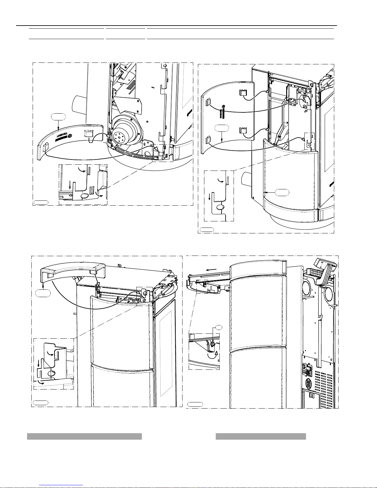
4.6 CONNECTING THE APPLIANCE TO THE FLUE OUTLET
Connection of the appliance to the flue outlet must be carried out in strict compliance with the instructions contained in
this booklet and particularly with those in Chapter 9.
The appliance is supplied with the control panel assembled symmetrically with the generator: the connection to the flue
outlet in this case must be carried out as indicated in figures 1, 2, 3. Pay particular attention when assembling the smoke outlet pipe
as it must be no less 15 mm from the control panel (Figure 2): if the pipe is positioned close to the panel it would certainly damage
the control panel (damage which is not covered by warranty).
Installed in this way the hot air can be channelled to the back using both vents.
Figura 2
Figura 1
1
5
Figura 3
Page 19

Page 19
manutenzione
If there is not sufficient depth the size can be reduced
to roughly 80 mm; follow the indications in figures 4, 5, 6,
7 and specifically:
- Remove the tank cover (Figure 4).
- Remove the 4 screws from the control panel (Figure 4).
- Shift the panel then fix with the screws removed earlier
(Figure 5).
- Pay particular attention when assembling the smoke
outlet pipe as it must be no less 10 mm from the control
panel (Figure 6): if the pipe is positioned close to the panel
it would certainly damage the control panel (damage which
is not covered by warranty). Installed in this way the hot air
can be channelled to the back using only the RH side vent.
It is strictly forbidden to use the LH side ducting.
Figura 4
Figura 5
Figura 6
10
Figura 7
Page 20

Page 20
manutenzione
14:30
WORK
Zona del display dove viene
visualizzato il giorno
corrente (per esempio 3 pallini = mercoledì).
Indicatore
livello
di ventilazione
Zona del display
visualizzati fasi di
funzionamento, ora....
dove vengono
"
Themocomfort On "
ovvero connesso
Indicatore
livello
di combustione
14:30
WORK
3
2
5
4
8
1
7
6
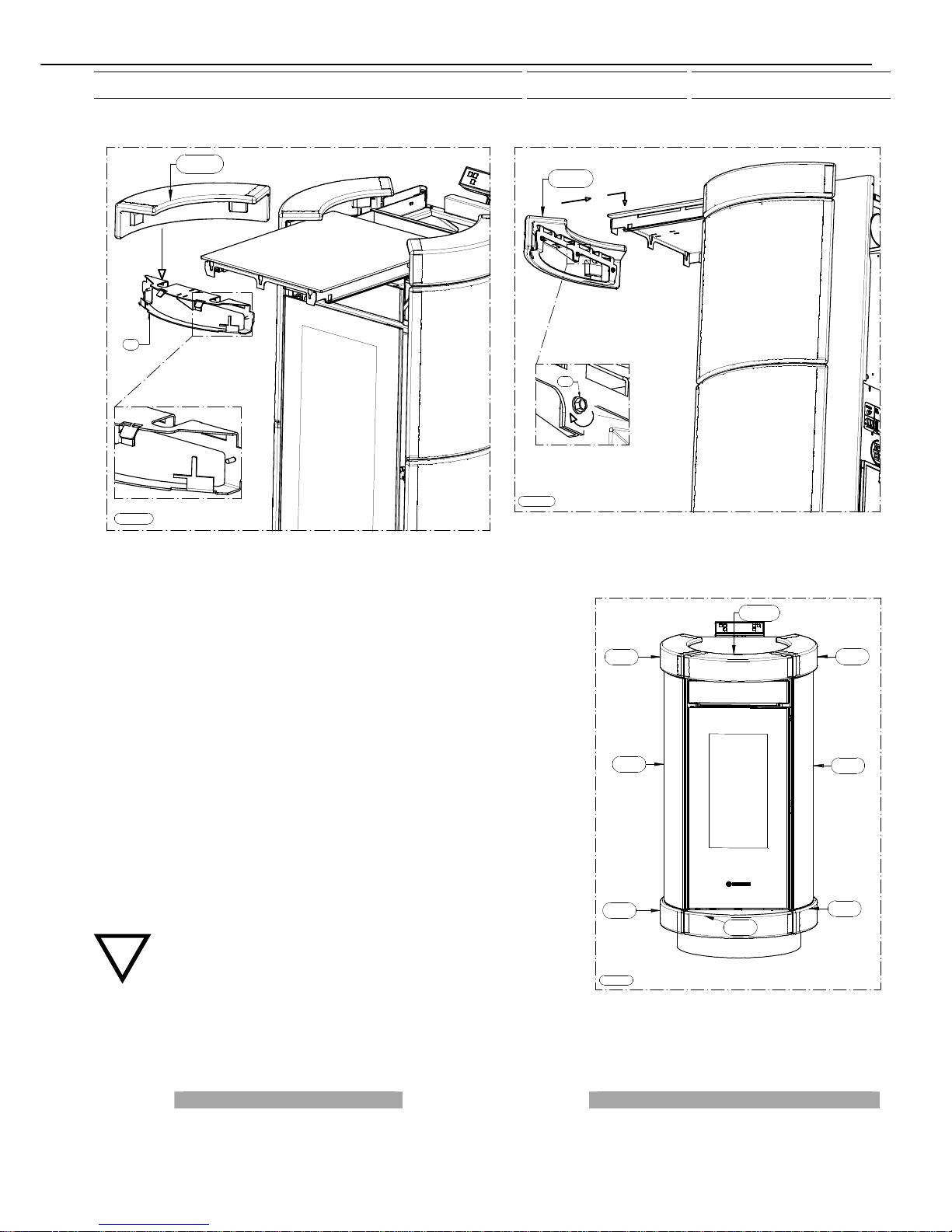
4.7 HANDLE
Your appliance is supplied with a handle for opening the firebox door; this tool must be used for opening the door to permit carrying
out cleaning operations (see paragraph 8). The handle, when not being used, can be stored at the back of the appliance on the
hook provided (see Figures 1 and 2).
5 – DESCRIPTIONS OF CONTROLS
There are two main control pushbuttons marked with the ventilation symbol (2) and the symbol of the flame (1). The flame
pushbutton (1) sets the power of the appliance with 5 levels available which are activated as the 5 bars light up in sequence on the
display (7). The off cycle is activated when all power bars are turned off. The fan button (2) controls the ventilation of the appliance.
It is activated when the smoke, detected by the smoke probe, reaches a temperature over 60°C.
The fan can be set to any of 6 speed levels displayed by the 6 bars progressively coming on on the display (7): when the appliance
is on the ventilation cannot be switched off.
5.1 DESCRIPTION OF CONTROL PANEL AND REAR PANEL
5.1 DESCRIPTION OF THE CONTROL PANEL
All controls and indicators are presented here below :
(1) Appliance on/off and flame adjustment button When you press this button
the appliance switches to START/WORK/ OFF
(appearing on the display 7). Press repeatedly to activate up to 5 bars on the
display (7)
(2) Ventilation setting button Press this button to set the desired level of
ventilation: up to a maximum of 6 speeds are available, indicated by the
lighting of the corresponding bars in the display (7). One bar is always lit
on the display even in OFF status.
(3) (4) Auxiliary setting buttons
Keys (3) and (4) are operating buttons necessary when on-off cycles are
programmed, for operative levels, clock setting, etc..
(5) Programming Enable / Disable / Chrono Reset buttons
(6) “MENU” selection button To access the main menu press the button
marked with 6. Press button 6 repeatedly to scroll the various windows:
date, programming setting,...
(7) Display
(8) Infrared remote control sensor
Figura 1
Figura 2
Page 21

Page 21
manutenzione
11
13
12
14
DAYS
DATA MON
2
3
5
4
7
6
1
8
00 : 00
LEGENDA KEY
Zona del display dove viene visualizzato il giorno corrente
(per esempio 3 pallini = mercoledì)
Display area in which the current day is displayed (for example,
3 dots = Wednesday)
Zona del display dove vengono visualizzati fasi di
funzionamento, ora,. . .
Display area in which the operation steps are displayed, time...
Indicatore livello di ventilazione Ventilation level indicator
"Thermocomfort On" ovvero connesso "Thermocomfort On" i.e. connected
Indicatore livello di combustione Combustion level indicator
Riarmo Reset
Spia motoriduttore Ratio motor led
5.1.2 APPLIANCE REAR PANEL
A description of the functions of the buttons and LEDs on the rear panel:
(11) Main switch 0-1
(12) Electrical power outlet 220-240V 50 Hz
(13) Overtemperature reset thermostat button cap
In the event of overtemperature this safety thermostat stops the loading of
pellets. To restart the appliance you need to wait until it cools down, then
verify the cause for the overheating, remove the cause, unscrew the
protective cap and press the button (13).
(14) Feed motor test indicator light When the pellet screw feeder is set
in motion the light must come on.
5.2 DAY AND TIME SETTING
The appliance must be energised and the rear switch in position "1". The
words START or WORK or OFF could be present on the display (7). To set the time and the day of the week carry out the
procedures described below. Press button (6) once;
the word DATA will appear on the display followed
by the words illustrated in the figure on the left. To
set the day press arrow button (3) and/or (4)
repeatedly until the desired day appears: (MON and
one dot for Monday -- TUE and two dots for Tuesday
-- WED and 3 dots for Wednesday -- THU and 4 dots
for Thursday -- FRI and 5 dots for Friday -- SAT and
6 dots for Saturday -- SUN and 7 dots for Sunday).
Then confirm the day by pressing the key (1). The 2
digits representing the hours will start flashing in the
display: it is possible to select the present hour using the arrow keys (3) and/or (4); the selection must be confirmed by pressing key
(1). The 2 digits indicating the minutes will start flashing: it is possible to select the present minutes using the arrow keys (3) and/or
(4), the selection must be confirmed by pressing the key (1). The day and time setting is now completed.
5.3 ON/OFF PROGRAMMING
The generator must be energised and the rear switch in position "1". The words START or WORK or OFF could be present on the
display (7).
DAYS
CRONO MON
3
2
5
4
8
1
7
6
DAYS
CRONO MON
3
2
5
4
8
1
7
6
00
: 00
ON
1
Page 22

Page 22
manutenzione
It is possible to carry out the weekly programming by setting up to 3 on/off cycles for each day from Monday to Sunday. To program
the appliance press button (6) twice until the word CRONO appears followed by the words illustrated in the figure above on the left.
Now you can begin programming the first day of the week - Monday - by pressing button (1). Press the arrow button (3) and/or (4)
to choose another day to be programmed, to confirm the selection press button (1) again. The words ON1 will appear on the display
followed by 2 blinking digits indicating the hours (figure above right). Press button (3) and/or (4) to enter the hour of the first cycle
start time. To confirm the selection press the button (1). The 2 digits indicating the minutes will start flashing. Press button (3)
and/or (4)to enter the minutes of the first cycle start time. To confirm the selection press the button (1). The first start up time for the
selected day has now been set. Then the inscription OFF1 will appear in the display and the two digits representing the hours will
turn on. When the (3) and/or (4) button is pressed the hour of the first off-cycle is entered.
To confirm the selection press the button (1). The 2 digits indicating the minutes will start flashing. By pressing the button (3) and/or
(4) the minutes for the first off-cycle will be entered. To confirm the selection press the button (1). This concludes the setting of the
first on-off cycle for the selected day. Later, it is possible to set the second on-off cycle (e.g. Monday) (shown with the display of
ON2 and OFF2) and the third Monday’s on-off cycle (shown with the display ON3 and OFF3). Next the display appears as
illustrated in the figure above on the left. Press the arrow button (3) and/or (4) to choose another day to be programmed, to confirm
the selection press button (1) again.
If you wish to copy all the on-off programs, for example the Monday settings, to the other days of the week, proceed as follows:
press button (6) until the word "CRONO" appears followed by the screen illustrated in the figure below on the left. Next press button
(2) and the display appears as illustrated in the figure below on the right: the program for Monday has been copied to Tuesday.
Press button (2) again to copy the program to Wednesday, Thursday ...
. In the programming menu if you wish, for example, to edit the programming for Sunday press button (3) and/or (4) to go to
Sunday and then press button (1). If the second on-off cycle is not required simply set the ON2 time as 00:00 and the OFF2 time as
00:00 .
The programming procedure ends when you confirm the last data entered by pressing button (6) or when you exit the programming
menu. During the START, WORK or OFF phases press button (5) to enable / disable the programming (Enabled = CR.ON appears
momentarily on the display together with the fixed presence of the chrono symbol on the right of the display (see figure below).
Disabled: message CR.OFF temporarily displayed and, at the same time, the chrono symbol on the right side of the display is not
present (see figure below): this function is useful if you wish to disable the established weekly program setting. Moreover, you can
reset, or delete, all the programmings by holding down (in OFF or START or WORK phase) button (5) for approximately 8 seconds;
the word "RESET CRONO" appears momentarily in order to indicate deletion of all the programmings previously set. With the
programming active, the operating conditions at the start-up (combustion power – ventilation speed) are the same as set-up before
the last off-cycle of the appliance: this is the case if the off-cycle has been done through the programming and not through a manual
action.
Manual shut down can only be carried out with the programming disabled. After shut down, by re-enabling the programming, at the
next start up controlled by the programming the appliance will be set at the first combustion power position and first ventilation
speed.
In the event of a programmed cycle on always ensure that the brazier is clean and seated correctly in its
lodging: failure to clean the brazier can reduce and/or affect the life of the spark plug as it would be
subjected to high temperatures due to poor cooling. When the programming is enabled (CR.ON appears
momentarily together with the fixed presence of the chrono symbol on the bottom of the display) any
additional chronothermostats (see para. 7.2) are disabled.
DAYS
CRONO MON
3
4
8
2
5
7
6
1
DAYS
CRONO TUE
Copy
3
4
8
2
5
7
6
1
Page 23

Page 23
manutenzione
3
4
8
2
5
7
6
1
LEVEL 1
WORK
14:30
14:30
WORK
Programmazione
abilitata
Programmazione
disabilitata
5.3.1 ON-OFF PROGRAMMING DISPLAY
To view the programmings press button (6) 5 times until the words "Show Chrono" appear.
After a few seconds the display appears as illustrated in the figure below on the left. Press button (3) repeatedly to scroll the
programmings for all the days of the week (see figure below on the right):
press button (6) to exit.
Caution: the on-off programmings cannot be modified from the "SHOW CRONO" menu, this menu is used only for
viewing the programs that have been entered and/or edited through the "CRONO" menu.
5.4 OPERATING LEVEL SETTING
The appliance must be energised and the rear switch in position
"1".
The words START or WORK or OFF could be present on the
display (7).
Your appliance is delivered with an excellent program installed
that favours combustion yield; the program is called
LEVEL 1. If you are using pellets with an out-of-standard
incidence of residues after combustion in the brazier, alternative
levels may be selected:
LEVEL 2: this program increases the smoke suction unit speed acceleration. (program Level 2 increases air delivery to the burner
which promotes the combustion of tightly compacted pellets: this program reduces combustion efficiency).
LEVEL 0: when using too long pellets and/or flue outlets with very high vacuum, over 2 Pascal. When operating at LEVEL 0 the
burner becomes dirty very easily. The pellet consumption value is not affected by the operating level settings. Select the required
level by acting as follows:
press button (6) three times until the word LEVEL appears on the display after which the level set will appear (LEVEL 1 or LEVEL 2
or LEVEL 0). In order to change the operating level as key (3) is kept pressed, press the key (4). By holding down button (3) and
pressing button (4) repeatedly the level changes in the following sequence: LEVEL 2 ... LEVEL 0 ... LEVEL 1.
DAYS 10:45
MON
3
4
8
2
5 7
6
1
DAYS 10:45
MON
3
4
8
2
5
7
6
1
ON
1 11:15
OFF 1
13:45
Programming enabled
Page 24

Page 24
manutenzione
If the change is made while the appliance is running the difference in the flame will be apparent. It is
mandatory to pay particular care when selecting the most appropriate operating cycle for your
installation. After the selection of the operating cycle a thorough cleaning of the brazier is mandatory.
For the entire procedure to be confirmed and to move back to the appliance status display, key (6) must
be repeatedly pressed.
6 – USE OF THE APPLIANCE
Your appliance has obtained the CE marking and has been made to run for 1 hour to check that it functions correctly. It has also
undergone numerous tests as detailed in the test check sheet supplied with the generator. The product must not be used by
children, by persons with physical or mental impairments, by persons who are not familiar with the instructions for use and
maintenance of the product (the instructions are found in this booklet). CAUTION: Before each use make sure that the burner is
clean and positioned correctly in its lodging, check that the ash pans are clean and shut tight and check that the firebox door is
locked. WARNING: the door must always remain shut tight when the appliance is operating. It is strictly forbidden to open the door
while the appliance is in operation. While the appliance is in operation the smoke exhaust pipes and the appliance can reach
extremely high temperatures: do not touch them! Do not expose your body to hot air for long, do not overheat the room in which the
appliance is installed, as these actions could cause health problems. Do not expose plants or animals directly to the hot air flow as
this could have noxious effects on them. It is strictly forbidden to use any type of fuel (liquid, solid...) to light the appliance:the
appliance must light up automatically as designed and described in this installation, use and maintenance booklet; in this regard, it
is strictly prohibited to pour pellets (or other material) directly into the brazier. Do not place non-heat resistant or inflammable or
combustible objects in the vicinity of the appliance: keep them at a suitable distance. Do not place wet clothing to dry on the
appliance.
When using a clothes horse, keep at a suitable distance. It is strictly prohibited to disconnect the appliance from the electrical
power mains while it is in operation.
6.1 SWITCHING ON THE APPLIANCE
Before using the appliance check that all the movable parts are in place; also remove any labels and stickers from the glass to
avoid having permanent traces remain on the surfaces. Always ensure that the brazier is clean and seated correctly in its lodging
(see para. 8).
Turn the switch installed on the back of the appliance to position "1" (= ON). Press button (1) to start the start up phase. When key
(1) is repeatedly pressed, the desired combustion level can be set and it will be active at the end of the ignition stage. The electrical
heater will start to overheat and after a few minutes the first lot of pellets will start dropping into the brazier. This occurs because the
screw feeder has to fill up because it is completely empty. The first time the appliance is started up the start up phase will have to
be carried out twice for this very reason.
CAUTION: The start up phase (the word START appearing on the display) continues until the word
START remains lit. Once this phase has ended the word WORK appears on the display. The fan will
begin operating as soon as the combustion smoke reaches a suitable temperature. During the work
stage it is then possible to adjust combustion and the ventilation:
The combustion can be adjusted by 5 bars through button (1)), the ventilation setting can be set on 6 levels indicated by the
sequential lighting up of the corresponding bars on the display (through button (2)).
To turn the appliance on it is necessary for the inscription OFF to be present on the display: if it is not present, the key (6) must be
repeatedly pressed until the inscription OFF appears.
6.2 ADJUSTING COMBUSTION AND VENTILATION
The heating capacity is adjusted by pressing key (1) or on the remote control provided. Act on this command to adjust the quantity
of pellets fed to the firebox. Maximum combustion power is achieved when all 5 leds are lit.
Caution: the room fan starts up as soon as the temperature of the combustion smoke reaches a suitable threshold. The
fan setting is expressed visually by means of 6 different positions represented by 6 bars:press button (2) repeatedly to
regulate it. A slight vibration of the appliance is quite normal when it is running. One bar is always present on the display
even in OFF status.
Page 25

Page 25
manutenzione
8 R
9 R
10 R
3 R
2 R
4 R
1 R
6 R
7 R
5 R
11 R
12 R
13 R
6.3 INFRARED REMOTE CONTROL
A practical infrared remote control is supplied with the appliance: adjust the ventilation level by means of the left button, whereas
use the right button to start the appliance, to adjust the power and combustion level and to switch off the appliance. If the appliance
is supplied with a white radio control (optional) the infrared control only works when the MANUAL setting is set on the white
handheld radio control.
6.4 OPERATION OF THE WHITE HANDHELD RADIO CONTROL THERMOCOMFORT (OPTIONAL)
INTRODUCTION
The thermocomfort handheld radio control is the instrument that allows you to optimise both consumption and functions. Keep in
mind that radio wave transmissions can be affected by the surrounding environment: the presence of thick walls can reduce the
transmission that normally extends to 6-7 metres.
Caution: to guarantee optimal data transmission it is advisable to always place the radio control in its support in a vertical
position.
The following operations must be carried out the first time the appliance is started up:
- Turn the switch (11R) to ON (see drawing below)
- Connect the radio control by means of the battery charger supplied to the power line (it must be recharged for at
least 5 days), as the rechargeable batteries could be partially or completely flat. The appliance must be energised
and the rear switch turned to position "1".
CAUTION: the Thermocomfort function is disabled when the remote control is OFF. To enable it, in the START,
WORK, OFF phases, repeatedly press button (6) on the appliance's control panel until the word
"THERMOCOMFORT" appears on the display (7) followed by the words Thermocomfort Off". To activate the
Thermocomfort function simply press the button (3) on the appliance's control panel: " Thermocomfort On". To
return to the original operating function simply press the button (6) again on the appliance's control panel. At the
end of the winter season it is mandatory to recharge the batteries and switch off the radio control completely, by
means of the switch situated inside the battery compartment, in order to preserve the life of the batteries. The
batteries are guaranteed for 6 months. When the batteries are exhausted dispose of them safely. It is normal for
the temperature sensor to detect temperatures which are slightly different to the real ones: variations caused by
the environment in which the radio control is positioned and by the tolerance of the thermostat.
6.4.1 INDICATORS OF THE HANDHELD RADIO CONTROL
(1R) Flame selection button
(2R) Ventilation selection button
(3R) (4R) Auxiliary buttons
(5R) “Room temperature detected by the radio control's sensor” indicator
(6R) “Ventilation” indicator
(7R) “Combustion” indicator
(8R) “Room temperature setting” indicator: this is the room temperature
that you wish to reach by means of buttons 3R and 4R.
(9R) Area of the display where the operating program is displayed.
(10R) Battery charge level
(11R) Switch 0-1 radio control power
(12R) Battery charger connection
(13R) Code selector and batteries compartment cover
The Thermocomfort radio control can be used with 4 different operating
programs:
- Manual (MANUAL appears in area (9R) of the display).
- Automatic 5 (AUTO 5 appears in area (9R) of the display).
- Automatic 3 (AUTO 3 appears in area (9R) of the display) .
Page 26

Page 26
manutenzione
- Economy (ECONOMY appears in area (9R) of the display). To change the operating program turn the switch (11R) to "1". Press
and hold down button (3R) until the set program begins to blink on the display (9R). Now release button (3R) and press button (3R)
and/or (4R) repeatedly until you select the desired operating program.
MANUAL program (the "Thermocomfort ON" symbol blinks on the display of the appliance)In the MANUAL program the room
temperature thermostat is disabled. Press button (1R) and the flame symbol blinks. Press button (3R) to reduce the combustion
level as signalled by the power bars lighting up in sequence, vice versa press button (4R) to increase the combustion level.
The combustion level changes every time buttons (3R) and (4R) are pressed. Press button (2R) and the ventilation symbol blinks.
Press button (3R) to decrease the combustion level, vice versa press button (4R) to increase the combustion level. The ventilation
level changes every time buttons (3R) and (4R) are pressed. Caution: it is possible that, due to radio interference or sending
commands too close together, the changes will not be implemented. When using this program the infrared remote control can also
be used. It is normal that in the manual cycle the ventilation is often set at the maximum speed in order to cool the appliance body
more effectively.
AUTO 5 program (the "Thermocomfort ON" symbol is steady on the display of the appliance) In program AUTO 5 the room
temperature thermostat is enabled. The remote control adjusts the ventilation and combustion automatically in relation to the target
room temperature set in display area (8R). The desired room temperature is displayed in area (8R). You can vary the desired room
temperature by simply pressing button (3R) and/or (4R) (variation indicated in area (8R)). The remote control will set the maximum
combustion and ventilation levels and modulate them both as the room temperature (5R) approaches the target temperature (8R).
When the target temperature (8R) in the room (5R) is reached, the combustion level will stabilise on a bar as will the ventilation
level. Caution: it is possible that, due to radio interference, the commands sent to the generator will not be implemented. When
using this program the infrared remote control cannot be used. Caution: the power and the ventilation depend on the preset value, if
the required temperature is too high or not reachable the appliance could operate at maximum power for long periods of time.
AUTO 3 program (the "Thermocomfort ON" symbol is steady on the display of the appliance) In program AUTO 3 the room
temperature thermostat is enabled. The remote control adjusts the ventilation and combustion automatically in relation to the target
room temperature set in display area (8R). The desired room temperature is displayed in area (8R).
You can vary the desired room temperature by simply pressing button (3R) and/or (4R) (variation indicated in area (8R)). The
remote control will set the combustion power at level 3 and the ventilation at level 4 and modulate them both as the room
temperature (5R) approaches the target temperature (8R). When the target temperature (8R) in the room (5R) is reached, the
combustion level will stabilise on a bar as will the ventilation level. Caution: it is possible that, due to radio interference, the
commands sent to the appliance will not be implemented. When using this program the infrared remote control cannot be used.
Caution: the power and the ventilation depend on the preset value, if the required temperature is too high or not reachable the
appliance could operate at maximum power for long periods of time.
ECONOMY program (the "Thermocomfort On" symbol is steady on the display of the appliance) In the ECONOMY program the
appliance always operates at the minimum combustion level and the minimum ventilation level. When using this program the
infrared remote control cannot be used.
CAUTION: THE APPLIANCE MUST ALWAYS BE STARTED UP AND SHUT DOWN FROM THE CONTROL PANEL OR
THROUGH PROGRAMMING.
6.4.2 TRANSMISSION CODES SETTINGS.
The appliance must be energised and the rear switch in position "1". The words START or WORK or OFF could be present on the
display (7).
If there are several appliances installed in rooms closely to each other it may be necessary to set different transmission codes as
this type of interference deactivates operation of the optional Thermocomfort radio control. To change the transmission codes
proceed as follows:
-Disable the Thermocomfort function. To disable it, in the START, WORK, OFF phases, repeatedly press button (6) on the
appliance's control panel until the word "THERMOCOMFORT" appears on the display (7) followed by the words "Thermocomfort
On". To deactivate the Thermocomfort function simply press the button (3): "Thermocomfort Off". To return to the original operating
function simply press the button (6) again.
-Switch off the Thermocomfort radio control by pressing the button (11R) on the device.
-To change the transmission codes, open the cover (13R) and act as indicated in the figure below.
-Next switch on the radio control by pressing the button (11R).
Page 27

Page 27
manutenzione
-Activate the Thermocomfort function. To enable it, in the START, WORK, OFF phases, repeatedly press button (6) on the
appliance's control panel until the word "THERMOCOMFORT" appears on the display (7) followed by the words Thermocomfort
Off". To activate the Thermocomfort function simply press the button (3): "Thermocomfort On". To return to the original operating
function simply press the button (6) again. The radio control may still not function even after having changed the transmission
codes. If this occurs change the codes once again using the procedure described above.
LEGENDA KEY
Selettore codici per radiocomando palmare gestito via
onde radio
Code selector for handheld radio control controlled by radio
waves
6.4.3 CARE AND MAINTENANCE OF THE RADIO CONTROL
The radio control has been designed and produced to the strictest standards and must be handled with great care. If you observe
the guidelines set out below, the radio control will provide a long trouble-free performance:
-Protect the radio control against humidity! Precipitation, humidity and liquids corrode the electronic circuits. If the radio control is
wet, disconnect it immediately from a power source, remove the battery, open it and allow it to dry at room temperature.
-Do not use or store the radio control in dusty or dirty environments. The dust/dirt
could damage the movable parts of the radio control.
-Do not store the radio control in very hot environments. High temperatures could
shorten the life of the electronic devices, damage the batteries and deform or even
melt plastic parts. -Do not store the radio control in cold environments. When it heats
up (when it returns to normal operating temperature), humidity could form inside it and
damage the electronic circuits.
-Do not drop the radio control, do not hit or bump it and do not shake it. Actions such
as these could damage the internal circuits of the device.
-Do not use corrosive chemical substances, caustic solutions or detergents to clean
the radio control.
All the above guidelines apply equally to the radio control, the battery, the battery
charger, and all the accessories. The parts subject to wear (such as batteries,
keypads, lodging compartments, small compartment parts) are guaranteed for 6
months from the purchase date. The guarantee does not apply if the defect is caused
by non-conforming use and/or if the instructions and guidelines described above are
not observed to the letter. Devices or parts returned for replacement become the
property of Thermorossi. The presence of irregular black-blue lines on the display
(also present when de-energised and battery flat or missing) indicate that the glass screen of the display is damaged following a fall
or impact: in this case the breakage is not covered by the guarantee.
SELETTORE CODICI PER RADIOCOMANDO
PALMARE GESTITO VIA
ONDE RADIO
O
N
1
2
3
4
3
1
O
N
2
4
THERMOCOMFORT
3
5
4
7 6
Thermocomfort
On
11 R
12 R
13 R
A
Figura 1
Page 28

Page 28
manutenzione
6.5 FILTER
This practical device prevents the circulation of dust which is always present in household environments. The filter (marked by letter
A in the figure on the side) is installed at the back of the appliance (see figure 1 on the side). Clean frequently to ensure the
maximum availability of hot air when the appliance is operating (wash the filter
with cold water then dry thoroughly every 5 days).
6.6 CHANNELLING (DORICA PLUS ONLY)
To obtain an optimal flow of channelled hot air:
- Avoid narrow or reduced sections, sharp curves, downhill runs in the tubing.
- Reduce the horizontal runs as much as possible.
- Use pipes with smooth inner surfaces made of material capable of resisting
continuous temperatures of 150°C.
- Insulate pipes with mineral wool (resistant to at least 150°C).
If you follow the instructions given above it is possible to channel:
- up to 16 metres using 1 vent
- up to 8 metres using 2 vents
- up to 6 metres using 3 vents
- up to 4 metres using 4 vents
The appliance is supplied with both fittings already mounted. The air can be
ducted from the front or the back of the appliance by acting on the 2 levers
indicated in Figure 1 and Figure 2; to completely or partially channel the air to
the right rear pipe act on lever A (Figure 1), to completely or partially channel
the air to the left rear pipe act on lever B (Figure 2).
CAUTION: WHEN ONE OR BOTH DUCTING COLLARS ARE NOT BEING
USED TO CHANNEL THE AIR PUSH CHANNELLING LEVERS (A) AND (B)
TOWARDS THE FRONT OF THE APPLIANCE. IT IS MANDATORY
THEREFORE TO ENSURE THAT THERE ARE NO OBJECTS AND/OR
MATERIALS PRESENT AT THE BACK OF THE APPLIANCE THAT COULD
BE DAMAGED BY THE HEAT WHICH, IF THE CHANNELLING LEVER IS IN
THE INCORRECT POSITION (THAT IS POSITIONED TOWARDS THE BACK
OF THE APPLIANCE), WOULD DIRECT EXTREMELY HOT AIR
TOWARDS THEM. SEE INDICATIONS ON PARA. 4.1.
CAUTION: the channelling levers are extremely hot; it is mandatory to use the supplied glove.
A
Figura 1
B
Figura 2
Page 29

Page 29
manutenzione
7 - ADDITIONAL ROOM TEMPERATURE THERMOSTAT (not supplied)
ADDITIONAL CHRONOTHERMOSTAT - MODEM (not supplied )
The control panel ensures that your appliance is provided with all the required programming and temperature adjustment functions:
the appliance can be connected to an additional room temperature thermostat or to an additional chronothermostat:
---> for an additional room temperature thermostat connect terminals 7-8 directly to terminal bock CN7 on the board as illustrated in
Figure 1.
---> for the additional chronothermostat – modem connect terminals 9-10 directly to terminal bock CN7 on the board as illustrated in
Figure 1.
Contacts are defined as "CLEAN" contacts and they must never be fed with 220 V. It is strictly prohibited to supply any tension
whatsoever to the above-mentioned terminals as this would permanently damage the control board; such damage is not covered by
WARRANTY.
LEGENDA KEY
Cronotermostato (optional) Chronothermostat (optional)
(morsetti 9-10 Morsettiera CN7) (terminals 9-10 Terminal block CN7)
Termostato ambiente (optional)
Room thermostat (optional)
(morsetti 7-8 Morsettiera CN7)
(terminals 7-8 Terminal block CN7)
7.1 OPERATING WITH THE ADDITIONAL ROOM TEMPERATURE THERMOSTAT (not supplied)
An additional room temperature thermostat can be installed by connecting it to the board as indicated in Figure 1. The operating
principle is as follows:
-When the room temperature reaches the set temperature (only during the WORK phase) the thermostat closes the contact and the
appliance shifts to the minimum room fan speed and minimum combustion power. This condition is indicated on the display by the
blinking ventilation bar and combustion bar: the appliance ignores all commands transmitted to it. By using the room temperature
thermostat the appliance does not shut down, therefore electrical energy consumption is kept to the minimum and the appliance
has a longer life. -When the room temperature drops the thermostat opens the contact and the appliance returns to its original
position in terms of thermal power and ventilation. In this position the appliance can be started up automatically via the
programming.
CAUTION: Use N.O. (normally open) contacts for the connection to the additional room temperature thermostat.
The thermostat must have a thermal hysteresis that is not less than 2°C.
1
2
1
3
2
4
MORSETTIERA CN7
2
3
1
121011
9 78 6
( morsetti 9 - 10 Morsettiera CN7)
Cronotermostato (optional )
( morsetti 7-8 Morettiera CN7)
Termostato ambiente (optional )
245 3
1
8
5
6
7
10
9
Figura 1
Page 30

Page 30
manutenzione
7.2 OPERATING WITH THE ADDITIONAL CHRONOTHERMOSTAT (not supplied)
As an alternative to the room temperature thermostat, a chonothermostat can be installed by connecting it to the board as indicated
in Figure 1. Using this output when the chronothermostat contact closes the START cycle begins, whereas when the contact opens
the OFF cycle begins. The operating level at start up (combustion power - fan speed) is the same as the level used before the last
time the appliance shut down.
CAUTION: when using the chronothermostat program up to a maximum of 3 on-off cycles without setting the desired
target temperature or set it at the highest possible value for the chronothermostat.
At the end of the preset time the contact will open and perform the appliance shut down process. Similarly at the preset startup time
the contact will close and initiate the START cycle. The chronothermostat can be used to program start up and shut down times and
dates for the appliance. It is therefore possible to program a momentary shut down of the appliance according to the preset time.
Do not shut down the appliance according to the room temperature.
It is mandatory to deactivate the “Crono” symbol on the display (see para. 5.3) if an external chronothermostat is used.
CAUTION: The manufacturer denies all responsibility for the life of the electrical heater if subjected to excessive start ups.
It is recommended not to set the desired room temperature or to set it at the highest possible value for the
chronothermostat in order to avert this danger.
CAUTION: Use N.O. (normally open) contacts for the connection to the chronothermostat.
CAUTION: In the event of connections to the chronothermostat Thermorossi shall not be held responsible for the
appliance not starting up, smoke leaks, breakage of the lighting component. In the event of a programmed cycle on always
ensure that the brazier is clean and seated correctly in its lodging. A maximum of 3 on-off cycles per day are permitted.
The chronothermostat must have a thermal hysteresis that is not less than 2°C.
8 - CLEANING AND MAINTENANCE
8.1 FOREWORD
Before commencing any operation disconnect the appliance from the electric power outlet. Your pellet appliance needs
maintenance; it requires a few simple, basic but frequent control and general cleaning operations. This will guarantee
consistently smooth operation and optimal efficiency of the appliance. In the event of prolonged non-use of the product it
is mandatory to check for obstructions in the smoke channel and flue outlet before putting it back into use. It is
necessary to accurately follow the directions given below: otherwise severe damages may occur for the product, the
installation, objects and the people who use the generator. Failure to observe cleaning and maintenance instructions will
immediately void the warranty . Warning: do not wet the appliance and do not touch the electrical parts with wet hands.
Never vacuum hot ash: this could damage the vacuum device. All the cleaning operations described in this manual must
be carried out when the appliance is cold.
8.2 CLEANING AND MAINTAINING THE APPLIANCE
The cleaning and maintenance operations can be carried out by
the user.
EVERY DAY clean out all the combustion residues from the
brazier B and remount the brazier B and catalyst A correctly (figure
2, 2A, 2B). To open and close the door use the tool provided (see
para. 4.5). (Figure 2A shows a clean brazier) CAUTION: make
sure, before every start up, that the brazier is clean and if
necessary also thoroughly clean the burner with a suction unit. To
guarantee correct operation of the appliance, carefully clean the
area around the spark plug:this will guarantee the correct operation
of the appliance.
EVERY 3 DAYS lift and drop the tube scraper rods several times
(figure 1); to access the tube scraper rods you need to firstly
remove the tank cover.
EVERY 5 DAYS clean the room air filter located at the back of the
appliance (figure 6).
EVERY WEEK clean out all the ash from the ash pans V and V1
(figure 2B and figure 3): to access the compartment V simply lift
out the brazier B and the catalyst A.
EVERY 2 WEEKS clean the smoke exhaust "T" at the appliance
inlet .
EVERY MONTH inspect and clean the vents identified as "A1"
Figura 1
Page 31

Page 31
manutenzione
(figure 5). To access the vents open the door, remove the
ash pan and lift up the cover.
EVERY MONTH check that the smoke exhaust is free
from fly ash deposits, particularly in the initial sections.
EVERY MONTH vacuum the ash deposited on the
bottom of the tank (when the tank is empty).
EVERY 3 MONTHS clean the smoke channels and check
that they are airtight.
TWICE A YEAR clean the flue outlet and inspect the
smoke exhaust pipe for airtightness.
TWICE A YEAR remove the back of the combustion
chamber (figure 4A, 4B, 4C) to clean it by lifting and
rotating it outwards.
AT THE END OF THE WINTER SEASON OR
WHENEVER NECESSARY thoroughly clean the
appliance firebox, using brushes and vacuum cleaner.
A vacuum device simplifies the cleaning procedure. Use
a damp cloth or a scrunched up piece of newspaper,
dampened and rolled in the ash, to wipe the glass until it
is perfectly clean. Do not clean the glass while the
appliance is operating. The glass remains reasonably
clean if the catalyst - deviator blade is installed correctly
in the brazier as shown in figure 5A. The front profiles,
the glass elements and the casing must be cleaned,
when the appliance has cooled, with a special soft
microfibre cloth for delicate surfaces such as lenses,
glasses, monitors, etc..., and water. CAUTION: a daily
deposit of soot and combustion residues on the glass is
quite normal.
It is normal for the ash to fall to the floor when the door is
opened. CAUTION: after cleaning it is mandatory to
carefully check that the combustion chamber door is
firmly closed and airtight. CAUTION: the smoke channel
and flue outlet generator must be cleaned in accordance
with the specifications described above and use of
inflammable products is strictly forbidden: using
inflammable products can create dangerous situations.
Failure to carry out the necessary maintenance or if only
partial maintenance is carried out will affect the correct
functioning of the appliance. Any problems resulting from
total or partial lack of maintenance will immediately void
the warranty. CAUTION: if the appliance remains inactive
(not used for over a month) the appliance, the smoke
discharge tube and the flue outlet must be thoroughly
cleaned and checked for any possible obstructions (e.g.
birds nests) before restarting.
Figura 2
A
B
Figura 2 A
A
B
Page 32

Page 32
manutenzione
Figura 2 B
B
A
V
Figura 3
V1
Page 33

Page 33
manutenzione
Figura 4A
Figura 4 B
Page 34

Page 34
manutenzione
Figura 4 C
Figura 5
A 1
Page 35

Page 35
manutenzione
8.3 CHARGING THE BATTERY OF THE WHITE THERMOCOMFORT HANDHELD RADIO CONTROL (optional)
As soon as the battery symbol on the display begins to blink,
as shown in the drawing, the battery needs to be charged.
While it is being charged and consequently while it is
connected to the electrical power mains the battery symbol
blinks continuously even when the batteries of the radio
control are completely charged. This operation is necessary
as otherwise the communication between the appliance and
the radio control could be cut off. The batteries of the
handheld radio control require regular recharging in relation to
the amount of use made of it The duration of the battery
charge is variable and depends on how often the remote
control is used. The batteries must be recharged using the
supplied battery charger:
INPUT 100V-240 V 50/60 Hz 0.3/A OUTPUT 5.5 V 750 but
the battery charger must be connected to a 220-240V 50Hz
power mains. To obtain a total recharge of the batteries they
must be charged for at least 5 days: lower charge times could
reduce the duration and life of the batteries. It is completely
normal during the battery recharge process for symbols
and/or lines to appear haphazardly on the display. The
optimal battery autonomy is achieved after several battery
charge / discharge cycles. If the radio control is not used for more than one week it is mandatory to switch it off completely in order
to preserve the life of the batteries. Turn the switch located in the battery compartment to 1, that is, OFF.
The batteries are guaranteed for 6 months.
Caution: Use only the battery charger provided by Thermorossi. The use of any other type of battery charger will invalidate
the product warranty. Flat batteries must be removed and safely disposed of. Use rechargeable AAA 1.2 V min. 750 mAh
batteries. Use only rechargeable batteries but do not mix different brands and types.
Figura 6
Page 36

Page 36
manutenzione
8.4 BATTERY REPLACEMENT FOR INFRARED REMOTE CONTROL
When the infrared remote control does not send out the transmission signal (led on), the battery must be replaced. Use a Phillips
screwdriver of proper size, to separate the half shells and replace the battery. The dead battery must be disposed of safely.
8.5 REPLACING THE BUFFER BATTERY OF THE CONTROL PANEL
Inside the control panel there is a buffer battery type CR 16 32 When the
time and programming are not being memorised (this malfunction is not
considered a defect as it is the result of normal wear/consumption) replace
the battery by removing the 4 screws at the back of the control panel. The
dead battery must be disposed of safely.
LEGENDA KEY
Batteria tampone CR1632 Buffer battery CR1632
Batteria tampone CR1632
Page 37

Page 37
manutenzione
9 – SMOKE DISCHARGE TUBE AND VENTILATION OF THE ROOMS
9.1 FOREWORD
Due to the frequent accidents caused by poor functioning of flue outlets installed in private dwellings, we have
prepared the following paragraph to assist the installer in his inspection of the parts concerned with eliminating the
gases produced by combustion.
The smoke outlet must be fitted in compliance with standard UNI 7129/92, UNI 10683 and EN 14785 and it must
observe the reference values laid down in the standard, in particular, the outlet must comply with fire prevention
regulations (therefore it must be able to withstand the action of a fire: in case of fire call the fire brigade immediately).
This chapter is not intended to replace UNI 7129, UNI 10683 and EN 14785 standards to which it refers. The
qualified installer must in any case be fully aware of these standards and any amending versions. It is important to
carefully follow the instructions set out below: failure to observe these instructions could cause serious damage to the
product, to the system, to objects and to persons using the generator.
9.2 ROOM VENTILATION
CAUTION: the presence of extraction fans or similar appliances, if operating in the same room or space in which the
product is installed, could cause problems for the correct operation of the product.
CAUTION: do not obstruct the vents or the air inlets on the appliance.
The room where the appliance is installed must have a good air flow to guarantee air for the appliance for the combustion process
and for ventilation of the room. The natural air flow must take place directly through permanent openings on the outer walls or
through single or multiple ventilation ducting (paragraph 9.2.1).
The ventilating air must come from outside and if possible, away from sources of pollution. The openings in the walls must comply
with the following conditions:
• have an unobstructed section of at least 6cm² for each Kw of installed thermal power, with a minimum limit of 100cm²;
• be made in such a way that the vent openings, both on the inside and outside of the wall, cannot be obstructed;
• be protected with grills or similar systems that do not reduce the opening section indicated above;
• be situated at a height near floor level and they must not obstruct the correct operation of the combustion product discharge
devices; if this position is not possible the section of the ventilation openings must be enlarged by at least 50%.
9.2.2 VENTILATION OF THE ADJACENT ROOMS
The air flow can also be obtained from an adjacent room as long as:
• the adjacent room is equipped with direct ventilation in compliance with the paragraphs described above;
• only appliances connected to the exhaust pipe are installed in the room that is ventilated;
• the adjacent room is not used as a bedroom or a common area of the building;
• the adjacent room is not a room with a fire hazard, such as storage sheds, garages, combustible material store rooms, etc...;
• the adjacent room does not become a vacuum compared to the room to be ventilated due to a reverse draught effect (the reverse
draught can be caused by the presence in the room of either another heating appliance running on any type of fuel, a fireplace, or
any suction device, which have not been provided with an air intake);
• the air flow from the adjacent room to the room to be ventilated is unobstructed through the permanent apertures having an overall
net section of no less than that indicated above. These apertures can be obtained by enlarging the space between the door and the
floor.
9.2.1 SINGLE OR MULTIPLE VENTILATION DUCTING
If the combustion air is supplied through pipes, the available draught, produced by the installed appliance in use and by the
corresponding combustion product evacuation system, must be greater than the sum of the resistance offered by the pipes
(frictional resistance, resistance due to direction changes, cross-sectional restrictions, etc...).
The single ventilation pipes can be vertically and horizontally oriented: the length of the horizontal sections must be reduced to a
minimum.
The connectors between pipes with different orientations must not have any reduced cross-sections with sharp bends.
The angle of connection between the axes of two successive pipes must not be less than 90°.
For combustion air supplied through branched pipes, the sum of the resistance offered by the pipes (frictional resistance, resistance
due to direction changes, cross-sectional restrictions, etc....) can be a maximum of 10% of the available draught, produced by the
various appliances in use installed on the various floors and by the combustion product evacuation system.
The branched ventilation pipes must be vertically-oriented with an uphill run.
The inlet vent to the room to be ventilated must be located down low and in a position where it does not interfere with the discharge
of combustion products and must be protected by a grill or similar device.
Page 38

Page 38
manutenzione
9.3 SMOKE OUTLET
The smoke channel, the exhaust pipe, chimney and flue outlet (defined as the system for the evacuation of combustion
products), are parts of the heating system and they must comply with the legislative requirements of the Ministerial
Decree DM 37/08 (ex Italian Law 46/90) and to the applicable specific installation regulations, according to the type of
fuel. Fireplaces, heaters and barbecues must not be installed in locations where gas appliances type A and type B are
present and operating (for the classification see UNI 10642 and UNI 7129). The connection between the appliance and
the flue outlet must only receive exhaust from one heat generator.
9.3.1 CHIMNEY TYPES
The following types of chimneys, constructed as described, are possible:
• system: Chimney installed using a combination of compatible components (flue liner, insulation, outer casing etc…), constructed
or specified by a single manufacturer and CE certified in accordance with the applicable standard;
• Composite chimney: Chimney installed or constructed on site using a combination of compatible components such as flue liner
(wall directly in contact with the smoke), and possibly also insulation and outer casing (wall) that may be supplied by different
manufacturers or by the same manufacturer.
• Relining: operation involving the installation of a specific pipe in an existing shaft (even if newly constructed) made of noncombustible materials, free from obstructions and for single use.
9.3.2 FLUE OUTLET / FLUE SYSTEM COMPONENTS
Every chimney must have minimum number of components as laid
down by standard UNI EN 1443 which are also indicated in the
figure on the left:
wall outlets, that is outlets installed on the outer front wall
without the use of a chimney/flue outlet /flue pipe to convey
the combustion products to the roof, are strictly prohibited.
ISPEZIONE
COMIGNOLO E
CANNA FUMARIA
SECONDO NORMA
UNI 10683
INTERNO ESTERNO
Tutte le tubazioni devono
essere termicamente isolate.
Tutte le tubazioni devono
essere termicamente isolate.
ISPEZIONE
COMIGNOLO E
CANNA FUMARIA
SECONDO NORMA
UNI 10683
Tutte le tubazioni devono
essere termicamente isolate.
LASTRA DI
COPERTURA
LAMIERA DI ACCIAIO
A TENUTA STAGNA
Components and accessories
of a chimney
KEY
1 Chimney
2 Flow path
3 Smoke discharge tube
4 Thermal insulation
5 External wall
6 Outer lining
7 Flue outlet section
8 Multiwall chimney
9 Connector
10 Flue pipe
11 Heat generator
Page 39

Page 39
manutenzione
9.3.3 CONTROLS PRIOR TO INSTALLING THE
APPLIANCE
The user must possess a certificate of
conformance for the flue outlet (Ministerial Decree
22 January 2008, no. 37).
The flue outlet must be built in compliance with
UNI 10683.
•The smoke exhaust shown in the following
figures is the best solution to ensure the
discharge of smoke even when the fan is not
operational, such as for example if there is an
electrical power failure. A minimum drop of 1.5
metres is required between the T terminal on the
outside of the building and the outlet at the back
of the appliance, to ensure that residual
combustion smoke is discharged in the case
described above (otherwise the residues would
stagnate inside the firebox and exhaust into the
environment with added the possibility of
explosions). The figures illustrate the best solution
for discharging the smoke out through the roof or
into the flue outlet.
If you prefer to exhaust the smoke from the roof
insert a union tee with inspection cap, connecting
brackets suitable for the height of the flue outlet,
flashing that crosses the roof and chimney cap to
protect against bad weather conditions. If you
decide to use the classic masonry exhaust
provide a union tee with inspection cap and
suitable supporting brackets. If the flue outlet is
too big it is necessary to insert a stainless steel or
porcelain-coated steel tube with a diameter not
exceeding 150mm. Seal area where the inlet and
outlet part of the smoke exhaust meets the wall. It
is strictly forbidden to apply mesh to the end of
the outlet tube, as it could cause the appliance to
malfunction.
LEGENDA KEY
COMIGNOLO E CANNA FUMARIA
SECONDO NORMA UNI 10683
CHIMNEY CAP AND FLUE OUTLET
ACCORDING TO UNI 10683
STANDARD
2 metri MAX. 2 metres MAX.
Pendenza non inferiore al 5% Minimum slope 5%
Ispezione INSPECTION
Tutte le tubazioni devono essere
termicamente isolate
All the pipes must be thermally
insulated
ALTEZZA SUPERIORE A 4metri HEIGHT MORE THAN 4m
2-3 metri MAX 2-3 metres MAX.
ISPEZIONE INSPECTION
If the smoke tube is installed in a fixed position it
is advisable to provide inspection openings for
clean-out purposes especially in the horizontal
sections. See the diagram. These openings are
essential to allow for the removal of ash and
unburned products which tend to accumulate
along the discharge path.
The appliance operates with the pressure in the
combustion chamber lower than atmospheric
pressure, whereas the discharge of smoke to the
chimney is slightly pressured, consequently the
discharge system must be hermetically sealed.
The smoke discharge tube must be made from
suitable materials such as for example:
INTERNO – ESTERNO INNER - OUTER
porcelain-coated steel tubes, and the various fittings sealed with red silicone (resistant to 350°C). The outer casing of the tube must
be made with insulating material (mineral wool, ceramic fiber) or use pre-insulated tubing.
THE FLUE OUTLET MUST BE USED ONLY FOR THE APPLIANCE .
ISPEZIONE
2 - 3 metri MAX.
ISPEZIONE
ISPEZIONE
2
m
e
t
r
i
M
A
X
.
P
e
n
d
e
n
z
a
n
o
n
i
n
f
e
r
i
o
r
e
a
l
5
%
ALTEZZA SUPERIORE A 4 metri
COMIGNOLO E CANNA FUMARIA
SECONDO NORMA UNI 10683
Tutte le tubazioni devono
essere termicamente isolate.
Page 40

Page 40
manutenzione
It must be possible to inspect and remove all the smoke tube sections for clean-out purposes.
CAUTION: if the flue outlet is not sufficiently insulated and /or if it is too long it could generate condensation.
It is mandatory to provide a condensation drain near the smoke outlet of the appliance. The appliance must
always and only be installed in a single flue outlet system dedicated exclusively to the appliance.
If the generator is connected to a non-compliant flue system the appliance could rapidly deteriorate due to an abnormal,
continuous overheating: in this case the damaged parts will not be covered by warranty.
IF THE CHIMNEY CATCHES FIRE DO NOT HESITATE TO CALL THE FIRE BRIGADE IMMEDIATELY.
10 – ALARMS
The appliance is programmed to communicate 7 fundamental alarms. The alarms are listed below:
AL PE: is communicated when the temperature during the WORK mode drops below the fixed threshold:
this indicates that the appliance is switching off due to lack of pellets. To reset the alarm simply press the flame button (1):
The appliance will begin a new start up phase. It is mandatory to empty and clean the brazier, and then to fill the pellet
tank before repeating the START phase.
AL AC: appears once the START phase has finished if the smoke does not reach a certain temperature. To reset the alarm simply
press the flame button (1):
the appliance will begin a new start up phase. It is mandatory to empty and clean the brazier before repeating the START
phase: pellets emptied from the brazier must not be fed into the tank.
AL OP: this occurs when the smoke outlet is partially blocked. To reset the alarm the power to the appliance must be switched off
then on by turning the switch 0-1 at the back of the appliance.
Before restarting the appliance check for any irregularities such as blocked flue outlet, open firebox door... and solve the
problem.
AL T max: appears when the temperature of the appliance body exceeds 125°C. Once the causes for the overtemperature have
been identified and remedied unscrew the plastic cover from the thermostat located at the back of the appliance and press the
button (the temperature of the appliance must cool down).
To reset the alarm the power to the appliance must be switched off then on by turning the switch 0-1 at the back of the
generator.
AL SMOKE TEMP SENSOR: appears when the smoke thermocouple is damaged or absent.
AL SMOKE FAN: activates when the smoke suction unit sensor detects a very slow rotation speed:
clean the vent A3 , the smoke channels and the flue outlet (see para. 8). If the problem persists contact the
technical assistance service.
AL SMOKE RPM SENSOR: trips when the smoke suction unit revolution sensor fails to detect any rotation; the smoke suction unit
is not working, call the technical assistance.
To reset the alarms the power to the appliance must be switched off then on by turning the switch 0-1 at the back of the generator.
Page 41

Page 41
manutenzione
11 - ELECTRICAL WIRING
LEGENDA KEY
Termocoppia Thermocouple
Pannello Comandi Control panel
Connettore per Micro SD card Connector for Micro SD card
Crono modem Chrono modem
Termostato Amb. Room thermostat
Termostato 95° Thermostat 95°C
Pressostato Pressure switch
Aspiratore fumi sensore Hall Hall sensor for smoke suction
unit
Motoriduttore - spia verde Ratio motor - green LED
Termostato riarmo Reset thermostat
Aspiratore fumi 220V 50 Hz Smoke suction unit 220V 50
Hz
Ventilatore Ambiente Room fan
Resistenza Heater
Fusibile 3.15 A Fuse 3.15 A
220 V 50 Hz
Comandi
Pannello
Termostato Amb.
Termostato 95°
Crono modem
9 8 67 5
Aspiratore fumi - 220 V 50 Hz
Motoriduttore - spia verde
Ventilatore Ambiente
5
1
2
1
3
2
4
Fusibile 3.15 A
Resistenza
9
7
6
8
10
Termostato Riarmo
Sensore Hall
Aspiratore fumi
Pressostato
134 210
Fusibile 3.15 A
Termocoppia
Connettore per
Micro SD card
Page 42

Page 42
manutenzione
12 - INFORMATION FOR THE SKILLED TECHNICIAN
12.1 MAIN COMPONENTS AND THEIR OPERATION
SMOKE PRESSURE SWITCH
This is a safety switch that stops the screw feeder motor whenever necessary. The main cause for the pressure switch tripping is a
blocked flue outlet or smoke exhaust pipe. Note that it is strictly forbidden to apply any kind of mesh screen to the end of the pipe.
When the holes of the mesh clog up they create a plug that trips the pressure switch which stops the pellet feeder.
SCREW FEEDER MOTOR
This motor is powered at regular on/off intervals controlled by a microprocessor. The operation of this motor is affected when:
-The motor's thermal cutout trips.-The pressure switch trips due to blocked smoke exhaust.
-Pellets finished.-Voluntary shut down of the appliance. -The manual reset thermostat trips at 125°C
ROOM FAN
Starts automatically as soon as the smoke thermocouple detects a suitable smoke temperature. Similarly it stops when the fuel is
finished or during a voluntary shut down when the smoke thermocouple detects a suitable temperature for activating (to a maximum
of 20 minutes).
SMOKE SUCTION UNIT
This is activated when the appliance starts up. In the first minute it «washes» the smoke discharge tube, that is, it functions at
maximum working rate. Once this time has elapsed it self-adjusts to the optimal speed. The exhaust continues to operate for
approximately twenty minutes from the time the appliance is switched off to allow for the evacuation of all the smoke and for safety
purposes.
THERMOCOUPLE
Its function is to verify the temperature of the combustion smoke: when the smoke temperature exceeds a certain value it indicates
that the appliance is on. Similarly, when the temperature drops below a certain limit it causes the presence of AL PE on the display.
TANK SAFETY THERMOSTAT
This thermostat starts operating as soon as the temperature in or near the pellet tank approaches 95°C and sends an immediate
signal to the room fan to operate at maximum power.
125°C MANUAL RESET THERMOSTAT
When the temperature exceeds 125°C the pellet feed screw shuts down. Display shows the inscription “AL T max”. Once the
causes for the overtemperature have been identified and remedied the appliance can be reactivated by unscrewing the plastic
cover of the thermostat located at the back of the appliance and pressing the button (the appliance temperature must have
considerably dropped).
GLOW PLUG
It is activated in the START phase. Heats the air to 800°C, which assist the first combustion of the pel lets present in the brazier.
The spark plug is guaranteed for a period of 6 months.
12.2 REQUIREMENTS NECESSARY FOR CORRECT INSTALLATION AND OPERATION
• Read this instruction booklet.
• The appliance must always be switched off from the control panel. It is forbidden to switch off the appliance by means of the
switch installed on the back of the heater.
• The appliance must never be disconnected from the electrical power supply and the power supply must never be cut off during
normal operation. Whenever the appliance is deliberately disconnected from the electric power supply smoke could be emitted into
the room.
• Do not install the appliance with horizontal wall outlets only: Evacuation of products of combustion by natural draught must always
be guaranteed as well. Unsuitable installation of the outlets could cause a forced shut down of the appliance due to overpressure of
the exhaust smoke caused by a gust of wind.
• At the first startup, run the appliance at the maximum power and minimum ventilation for at least ten hours in a well-ventilated
room, in order to dispose of the smoke generated by the complete dryness and baking of the silicates contained in the enamel
coating of the combustion chamber.
• Do not install a grill or outlet terminal that could slow down the flow of the combustion gases: this would obviously cause the
appliance to malfunction.
• Keep the appliance clean and check the burner as described in these instructions.
• Clean the smoke outlet regularly.
• Use good quality pellets: use of poor pellets can result in up to 50% less efficiency.
• The pellets must be stored in a well-ventilated, dry place.
• Sizing of the chimney liner:
Painted aluminized steel tubes (1.5 mm minimum thickness), Aisi 316 stainless steel tubes or 0.5 mm enamelled tubes may be
used.
Minimum vertical length 4 m / Maximum vertical length 8 m / Length with minimum slope 5% 0.5 m
Page 43

Page 43
manutenzione
Maximum number of elbows at least 0.5 m apart: 2
• The appliance door must always remain closed during normal operation.
• Do not touch hot outer surfaces, unless with special equipment.
• Do not pour the pellets directly into the brazier.
• Keep fuel and inflammable materials at a suitable distance.
• Use only original spare parts supplied by the manufacturer.
12.3 TROUBLESHOOTING CAUSE-SOLUTION
PROBLEM CAUSE SOLUTION
PELLET TANK IS EMPTY
(DISPLAY SHOWS THE INSCRIPTION “AL PE”)
EMPTY THE BURNER AND CLEAN IT UP AS INDICATED IN
PARA. 8
THEN FILL UP THE TANK WITH PELLETS
FEEDER SCREW BLOCKED BY FOREIGN OBJECT SUCH AS
NAIL, NYLON, PIECE OF WOOD
REMOVE THE FOREIGN OBJECT INSIDE THE TANK.
(DISPLAY SHOWS THE INSCRIPTION “AL PE”)
CUT OFF THE POWER AND REMOVE THE FOREIGN
OBJECT.
SMOKE EXHAUST NOT FREE, OR WITH TERMINAL THAT
OBSTRUCTS THE PASSAGE OF SMOKE
(DISPLAY SHOWS THE INSCRIPTION “AL OP”)
EMPTY THE BURNER AND CLEAN IT UP AS INDICATED IN
PARA. 8.
THEN CHECK THE SMOKE EXHAUST AS IT COULD BE
DIRTY OR CLOGGED
OUTLET TERMINAL CLOGGED BECAUSE A GRILL OR
TERMINAL HAS BEEN INSERTED WHICH PREVENTS THE
FREE PASSAGE OF SMOKE
(DISPLAY SHOWS THE INSCRIPTION “AL OP”)
EMPTY THE BURNER AND CLEAN IT UP AS INDICATED IN
PARA. 8.
THEN REMOVE THE TERMINAL AND REPLACE IT WITH A
MORE SUITABLE ONE.
GUST OF WIND WHICH HAS MADE THE APPLIANCE GO INTO
SAFETY MODE
(DISPLAY SHOWS THE INSCRIPTION AL OP)
EMPTY THE BURNER AND CLEAN IT UP (SEE PARA. 8)
SWITCH THE POWER SUPPLY TO THE APPLIANCE OFF
THEN BACK ON AGAIN
THE PELLET SCREW MOTOR DOES NOT WORK REPLACE THE PELLETS SCREW MOTOR
PELLETS DO NOT DROP INTO THE
BURNER
THE RESET THERMOSTAT TRIPS AND LOCKS THE
GEARMOTOR
(DISPLAY SHOWS THE INSCRIPTION AL T max )
THE ROOM FAN IS DAMAGED AND MUST BE REPLACED.
WAIT UNTIL THE APPLIANCE COOLS DOWN AND PUT
BACK INTO SERVICE THE RESET THERMOSTAT.
SMOKE EXHAUST NOT FREE, OR WITH TERMINAL THAT
OBSTRUCTS THE PASSAGE OF SMOKE
EMPTY THE BURNER AND CLEAN IT UP AS INDICATED IN
PARA. 8.
THEN REMOVE THE TERMINAL AND REPLACE IT WITH A
MORE SUITABLE ONE.
THEN CHECK THE SMOKE EXHAUST AS IT COULD BE
DIRTY OR CLOGGED
BURNER IS DIRTY EMPTY THE BURNER AND CLEAN IT UP AS INDICATED IN
PARA. 8.
THE DOOR IS NOT FIRMLY CLOSED / WORN GASKET CLOSE THE DOOR FIRMLY / REPLACE THE GASKET
EMPTY THE BURNER AND CLEAN IT UP AS INDICATED IN
PARA. 8.
EMPTY THE BURNER AND CLEAN IT UP AS INDICATED IN
PARA. 8.2. THEN SET THE OPERATING PROGRAM Level 2
PELLETS WITH DEPOSIT ABOVE PERMISSBILE LIMITS
EMPTY THE BURNER AND CLEAN IT UP AS INDICATED IN
PARA. 8.
CHANGE THE TYPE OF PELLETS
THE APPLIANCE ACCUMULATES
PELLETS IN THE BRAZIER WHILE
OPERATING
THE BURNER IS NOT PROPERLY PLACED ON ITS SEAT OR IT
STAYS LIFTED FROM ITS SEAT
EMPTY THE BURNER AND CLEAN IT UP AS INDICATED IN
PARA. 8.
THEN SET THE BURNER ON ITS SEAT PROPERLY
OCCURS THE FIRST TIME THE APPLIANCE IS SWITCHED ON
AS THE SILICONE PAINT IS BEING BAKED.
RUN THE APPLIANCE AT FULL POWER FOR 10 HOURS TO
COMPLETE THE BAKING.
THE SMOKE EXHAUST IS NOT SEALED CORRECTLY CHECK IF THE FLUE OUTLET IS SEALED CORRECTLY
CHECK THE CONDITION OF THE OUTLET TUBES AND IF
THE GASKETS ARE SEALED CORRECTLY
IF THE APPLIANCE STARTS TO SMOKE AFTER 25 MINUTES:
DIRTY BURNER, VERY DELAYED START
EMPTY THE BURNER AND CLEAN IT UP AS INDICATED IN
PARA. 8.
IF THE APPLIANCE STARTS TO SMOKE AFTER 25 MINUTES:
DELAYED START BECAUSE THE SCREW FEEDER IS EMPTY
EMPTY THE BURNER AND CLEAN IT UP AS INDICATED IN
PARA. 8.
THEN FILL UP THE TANK
THE APPLIANCE SMOKES
SMOKE PURGE VALVE TRIPPING FOLLOW ALL THE CLEANING AND MAINTENANCE
INSTRUCTIONS SET OUT IN PARA 8, INCLUDING THE
CLEANING OF THE FLUE OUTLET
DELAYED START BECAUSE THE SCREW FEEDER IS EMPTY
(DISPLAY SHOWS THE INSCRIPTION AL AC)
EMPTY THE BURNER AND CLEAN IT UP AS INDICATED IN
PARA. 8.
THEN FILL UP THE TANK
THE APPLIANCE SHUTS OFF A FEW
MINUTES AFTER THE END OF THE
START UP CYCLE
DIRTY BURNER, VERY DELAYED START
(DISPLAY SHOWS THE INSCRIPTION AL AC)
EMPTY THE BURNER AND CLEAN IT UP AS INDICATED IN
PARA. 8.
THEN FILL UP THE TANK
Page 44

Page 44
manutenzione
THE APPLIANCE DOES NOT START
UP
THE SPARK PLUG IS DAMAGED
(DISPLAY SHOWS THE INSCRIPTION AL AC)
EMPTY THE BURNER AND CLEAN IT UP AS
INDICATED IN PARA. 8.
THEN REPLACE THE SPARK PLUG
THE APPLIANCE ACCUMULATES PELLETS IN THE
BRAZIER
CLEAN THE GLASS MORE OFTEN. FOLLOW THE
CLEANING AND MAINTENANCE INSTRUCTIONS
OF THE APPLIANCE (SEE PARA. 8)
SET THE OPERATING PROGRAM “level 2”
THE APPLIANCE OPERATES WITH FREQUENT ONOFF CYCLES
THE APPLIANCE NEEDS TO OPERATE AT A
HIGHER POWER LEVEL TO REDUCE THE ON/OFF
ACTIONS.
THE GLASS IS COVERED IN BLACK
SOOT
THE CAST BLADE POSITION IS NOT CORRECT/ NO
BLADE
POSITION THE BLADE CORRECTLY / MOUNT THE
BLADE
ROOM TEMPERATURE THERMOSTAT IS SET TOO
LOW
THE APPLIANCE OPERATES AT INTERVALS
THE APPLIANCE MUST OPERATE FOR MORE
HOURS WITH MORE POWER: SET A HIGHER
TEMPERATURE
THE ROOM IS TOO LARGE, THE WALLS ARE COLD SEPARATE THE SPACES
THE APPLIANCE SHOULD OPERATE FOR MORE
TIME AND WITH MORE POWER
POOR PELLETS USE A DIFFERENT TYPE OF PELLETS IN
COMPLIANCE WITH OM 7135
THE APPLIANCE SEEMS NOT TO HEAT
CEILINGS TOO HIGH OR PRESENCE OF STAIRS
THAT DISPERSE THE HEAT ELSEWHERE.
SEPARATE THE SPACES
THE APPLIANCE SHOULD OPERATE FOR MORE
TIME AND WITH MORE POWER
THE APPLIANCE IS OFF BUT THERE ARE
UNBURNT PELLETS IN THE BRAZIER
PELLET TANK IS EMPTY (DISPLAY SHOWS THE
INSCRIPTION “AL PE”)
EMPTY THE BURNER AND CLEAN IT UP AS
INDICATED IN PARA. 8.
THEN FILL UP THE TANK
THE PROGRAMMING AND/OR TIME
DO/DOES NOT REMAIN IN THE MEMORY
THE BUFFER BATTERY TYPE CR1632 INSTALLED IN
THE CONTROL PANEL IS EXHAUSTED.
REPLACE THE BATTERY
(SEE PARA. 8)
THE APPLIANCE CARRIES OUT RANDOM
COMMANDS THAT HAVE NOT BEEN SET
ON IT OR RANDOMLY VARIES THE
VENTILATION AND COMBUSTION LEVEL
THE “OPTIONAL WHITE HANDHELD RADIO
CONTROL” IS INSTALLED AND THERE IS ANOTHER
THERMOROSSI PRODUCT NEARBY
CHANGE THE CODE SELECTOR
(SEE PARA. 6)
THE APPLIANCE DOES NOT CARRY OUT
THE COMMANDS SET BY THE OPTIONAL
WHITE HANDHELD RADIO CONTROL
THERE IS ANOTHERTHERMOROSSI PRODUCT
NEARBY
CHANGE THE CODE SELECTOR
(SEE PARA. 6)
THE TANK COVER DOES NOT RUN/SLIDE
ON THE TUBE SCRAPER KNOBS
THE APPLIANCE IS VERY DIRTY CLEAN IT UP AS INDICATED IN THE FIGURES 4A,
4B, 4C AND 5 (PARA. 8.2)
THE TANK COVER DOES NOT SLIDE
EASILY OR AT ALL
THERE ARE PELLETS IN THE RUNNERS USE A VACUUM CLEANER TO REMOVE THE
PELLETS FROM THE RUNNERS
IF THE RECOMMENDED REMEDIES DO NOT SOLVE THE PROBLEM CONTACT A TECHNICAL ASSISTANCE SERVICE
Page 45

Page 45
manutenzione
13 - SPARE PARTS
13.1 SPARE PARTS DORICA PAG. 1/5
70015019 ROSSA
70015667 ROSSO
70015022 ROSSA
70015021 ROSSA
70015630 BIANCA
70015634 BEIGE
70015663 GRIGIA
70015019 ROSSA
70015630 BIANCA
70015634 BEIGE
70015019 ROSSA
70015630 BIANCA
70015634 BEIGE
70015663 GRIGIA
70015663 GRIGIA
70015668 BIANCO
70015669 BEIGE
70015670 EASY
70015667 ROSSO
70015668 BIANCO
70015669 BEIGE
70015670 EASY
70015633 BIANCA
70015637 BEIGE
70015665 GRIGIA
70015632 BIANCA
70015636 BEIGE
70015664 GRIGIA
70015021 ROSSA
70015632 BIANCA
70015636 BEIGE
70015664 GRIGIA
Dorica 1
Page 46

Page 46
manutenzione
13.2 SPARE PARTS DORICA PAG. 2/5
70015019 ROSSA
70015630 BIANCA
70015634 BEIGE
70015638 NERA
70015019 ROSSA
70015630 BIANCA
70015634 BEIGE
70015638 NERA
70015019 ROSSA
70015630 BIANCA
70015634 BEIGE
70015638 NERA
70015021 ROSSA
70015632 BIANCA
70015636 BEIGE
70015640 NERA
70015021 ROSSA
70015632 BIANCA
70015636 BEIGE
70015640 NERA
70015022 ROSSA
70015633 BIANCA
70015637 BEIGE
70015641 NERA
70015020 ROSSA
70015631 BIANCA
70015635 BEIGE
70015639 NERA
70015020 ROSSA
70015631 BIANCA
70015635 BEIGE
70015639 NERA
70015020 ROSSA
70015631 BIANCA
70015635 BEIGE
70015639 NERA
70015020 ROSSA
70015631 BIANCA
70015635 BEIGE
70015639 NERA
70015135
Dorica 2
Page 47

Page 47
manutenzione
13.3 SPARE PARTS DORICA PAG. 3/5
60012609
70015111 Porta completa
70015014 Porta ghisa
70015195 Maniglia porta
70015046 Profilo ferma vetro
70015016 Vetro
60010336 Guarnizione vetro
60013919 Guarnizione porta
70015112 Cerniera
70015112 Cerniera
60011215 Dado ribassato
60004195 Dado
60004195 Dado
60011215 Dado ribassato
70015120
70012276 Bracere
70012277 Catalizzatore
70015680 Scheda potenza completa
70015023 Retro
60010344 Termostao 95°c
7
0
0
1
5
1
1
0
S
u
p
p
o
r
t
o
v
e
t
r
o
c
a
n
a
l
i
z
z
.
7
0
0
1
5
0
2
5
V
e
t
r
o
c
a
n
a
l
i
z
z
a
z
i
o
n
e
70015688 Coperchio completo
60010831
60010831
60013774 Coppia guide
70015026 Vetro
Dorica 3
60011798 Perno fermo
Page 48

Page 48
manutenzione
13.4 SPARE PARTS DORICA PAG. 4/5
C
O
M
N
.
O
.
60005254
60013559
70015673 Aspiratore completo
70015973
60011428
60010188
60010188
60010149 Coclea
60013555 Portasonda
60013339 Aspiratore
60013342
Dorica 4
60011630 Condensatore
Page 49

Page 49
manutenzione
13.5 SPARE PARTS DORICA PAG. 5/5
60006694
60006682
70015190
70015192
70014561
60013554 Ventilatore ambiente
60011796 Condensatore
60013663
60013776 Pannello comandi
60013777 Scheda comando
60013326 Vetrino
60013560 Batteria CR1632
60006637
70013584 Radiocomando comp.
60011787 Batteria ricaricabile
60011788 Caricabatterie
60013118 Supporto a muro
60013119 Coperchio batterie
60013139
70015088 Pannello completo
60011656 Interruttore 0-1
60011750 Termostato riarmo 125°c
Dorica 5
60010185 Boccola
70010402 Gruppo alimentazione pellet
60011428 Guarnizione
70010325 Flangia
70010234 Bussola fissaggio motore
60011793 Paracolpo
60011246 Motoriduttore
Page 50

Page 50
manutenzione
13.6 SPARE PARTS DORICA PLUS PAG. 1/5
70015019 ROSSA
70015667 ROSSO
70015022 ROSSA
70015021 ROSSA
70015630 BIANCA
70015634 BEIGE
70015663 GRIGIA
70015019 ROSSA
70015630 BIANCA
70015634 BEIGE
70015019 ROSSA
70015630 BIANCA
70015634 BEIGE
70015663 GRIGIA
70015663 GRIGIA
70015668 BIANCO
70015669 BEIGE
70015670 EASY
70015667 ROSSO
70015668 BIANCO
70015669 BEIGE
70015670 EASY
70015633 BIANCA
70015637 BEIGE
70015665 GRIGIA
70015632 BIANCA
70015636 BEIGE
70015664 GRIGIA
70015021 ROSSA
70015632 BIANCA
70015636 BEIGE
70015664 GRIGIA
Dorica plus 1
Page 51

Page 51
manutenzione
13.7 SPARE PARTS DORICA PLUS PAG. 2/5
70015019 ROSSA
70015630 BIANCA
70015634 BEIGE
70015638 NERA
70015019 ROSSA
70015630 BIANCA
70015634 BEIGE
70015638 NERA
70015019 ROSSA
70015630 BIANCA
70015634 BEIGE
70015638 NERA
70015021 ROSSA
70015632 BIANCA
70015636 BEIGE
70015640 NERA
70015021 ROSSA
70015632 BIANCA
70015636 BEIGE
70015640 NERA
70015022 ROSSA
70015633 BIANCA
70015637 BEIGE
70015641 NERA
70015020 ROSSA
70015631 BIANCA
70015635 BEIGE
70015639 NERA
70015020 ROSSA
70015631 BIANCA
70015635 BEIGE
70015639 NERA
70015020 ROSSA
70015631 BIANCA
70015635 BEIGE
70015639 NERA
70015020 ROSSA
70015631 BIANCA
70015635 BEIGE
70015639 NERA
70015135
Dorica plus 2
Page 52

Page 52
manutenzione
13.8 SPARE PARTS DORICA PLUS PAG. 3/5
60012609
70015111 Porta completa
70015014 Porta ghisa
70015195 Maniglia porta
70015046 Profilo ferma vetro
70015016 Vetro
60010336 Guarnizione vetro
60013919 Guarnizione porta
70015112 Cerniera
70015112 Cerniera
60011215 Dado ribassato
60004195 Dado
60004195 Dado
60011215 Dado ribassato
70015120
70012276 Bracere
70012277 Catalizzatore
70015680 Scheda potenza completa
70015023 Retro
70015983
60010344 Termostao 95°c
7
0
0
1
5
1
1
0
S
u
p
p
o
r
t
o
v
e
t
r
o
c
a
n
a
l
i
z
z
.
7
0
0
1
5
0
2
5
V
e
t
r
o
c
a
n
a
l
i
z
z
a
z
i
o
n
e
70015688 Coperchio completo
60010831
60010831
60013774 Coppia guide
70015026 Vetro
Dorica plus 3
70015986
60011798 Perno fermo
Page 53

Page 53
manutenzione
13.9 SPARE PARTS DORICA PLUS PAG. 4/5
C
O
M
N
.
O
.
60005254
60013559
70015983
70015986
70015673 Aspiratore completo
70015973
60011428
60010188
60010188
60010149 Coclea
60013555 Portasonda
60013339 Aspiratore
60013342
Dorica plus 4
60011630 Condensatore
Page 54

Page 54
manutenzione
13.10 SPARE PARTS DORICA PLUS PAG. 5/5
60006694
60006682
70015190
70015192
70014561
70012389
70012389
60013554 Ventilatore ambiente
60011796 Condensatore
60013663
60013776 Pannello comandi
60013777 Scheda comando
60013326 Vetrino
60013560 Batteria CR1632
60006637
70013584 Radiocomando comp.
60011787 Batteria ricaricabile
60011788 Caricabatterie
60013118 Supporto a muro
60013119 Coperchio batterie
60013139
70015088 Pannello completo
60011656 Interruttore 0-1
60011750 Termostato riarmo 125°c
Dorica plus 5
60010185 Boccola
70010402 Gruppo alimentazione pellet
60011428 Guarnizione
70010325 Flangia
70010234 Bussola fissaggio motore
60011793 Paracolpo
60011246 Motoriduttore
70012450
Page 55

Page 55
manutenzione
LEGENDA RICAMBI SPARE PARTS KEY
Rosso/a Red
Bianco/a White
Beige Beige
Grigio/a Grey
Nera Black
Coperchio completo Complete cover
Coppia guide Guide pair
Vetro Glass
Cerniera Hinge
Dado ribassato Low nut
Dado Nut
Supporto vetro canalizz. Upper front glass support
Vetro canalizzazione Upper front glass
Braciere Brazier
Catalizzatore Catalyst
Perno fermo Lock pin
Retro Back plate
Termostato 95°C Thermostat 95°C
Porta completa Complete door
Porta ghisa Cast door
Maniglia porta Door handle
Profilo ferma vetro Beading profile
Guarnizione vetro Glass gasket
Guarnizione porta Door gasket
Scheda potenza completa Complete power board
Aspiratore completo Complete suction unit
Coclea Screw feeder
Portasonda Probe holder
Aspiratore Suction unit
Condensatore Condenser
Radiocomando comp. Complete remote control
Batteria ricaricabile Rechargeable battery
Caricabatteria Battery charger
Supporto a muro Wall mount
Coperchio batterie Battery cover
Pannello comandi Control panel
Scheda comando Control board
Vetrino Glass
Batteria CR1632 Battery CR1632
Motoriduttore Ratio motor
Paracolpo Bumper
Bussola fissaggio motore Motor fixing bush
Flangia Flange
Guarnizione Gasket
Gruppo alimentazione pellet Pellet feeder unit
Boccola Bush
Ventilatore ambiente Room fan
Pannello completo Complete panel
Interruttore 0-1 Switch 0-1
Termostato riarmo 125°C Reset thermostat 125°C
Page 56

Page 56
manutenzione
NOTES
 Loading...