

THERMOROSSI BOSKY series Maintenance Manual

36011 Arsiero (vi) ITALY - Via Grumolo, 4 - tel. 0445 741310 fax 0445741657
www.thermorossi.com
USE AND MAINTENANCE GUIDE
CENTRAL HEATING COOKER
25 - 30 - F25 - F30 - 60 - 65 - 650 - 90 - 95 - 920

pg. 2
DECLARATION OF CONFORMITY
1. INTRODUCTION .................................................................................................................................................................................
1.1 General guidelines .............................................................................................................................................................
1.2 Safety guidelines ................................................................................................................................................................
1.3 Standards and recommendations .....................................................................................................................................
1.4 Transport and storage ........................................................................................................................................................
2. TECHNICAL CHARACTERISTICS ....................................................................................................................................................
2.1 Vitrification. .........................................................................................................................................................................
3. GENERAL DESCRIPTION ..................................................................................................................................................................
3.1 Operating principle ............................................................................................................................................................
3.2 Wood fuel ............................................................................................................................................................................
4. INSTALLATION ..................................................................................................................................................................................
4.1 Locating your Bosky central heating cooker. ...................................................................................................................
4.2 Installing the safety heat exchanger (only for 25 - 30 - F25 - F30 ) ................................................................................
4.3 Wiring diagram 25 - 30. ...............................................................................................................................................
4.4 Wiring diagram F25 - F30. ..............................................................................................................................................
4.5 Wiring diagram 60 - 65 - 650 - 90 - 95 - 920 without electric oven .................................................................................
4.6 Wiring diagram 60 - 65 - 650 - 90 - 95 - 920 with electric oven ......................................................................................
4.7 Guidelines for the hydraulic connections of the central heating cooker to the boiler coils ..........................................
4.8 Guidelines for the hydraulic connections of the central heating cooker to the boiler tubes with interspacing ...........
4.9 Recommendations for the execution of the hydraulic and electric system ....................................................................
4.10 Installation of casing for Bosky 25-30-F25-F30. ..............................................................................................................
5. OPERATION .........................................................................................................................................................................................
5.1 Description of parts and main controls of the central heating cookers ..........................................................................
5.2 Lighting and starting the central heating cookers ............................................................................................................
5.3 Operation of the central heating cookers .........................................................................................................................
5.4 Grate positions in the central heating cookers ..................................................................................................................
5.5 How to use the oven in central heating cookers F25-F30-60-90-920 .............................................................................
5.6 The fold-away towel rack (only for 25 - 30 - F25 - F30 ) ..................................................................................................
6. CLEANING AND MAINTENANCE ......................................................................................................................................................
6.1 General cleaning ................................................................................................................................................................
6.2 Ash ...............................................................................................................................................................................................
6.3 How to clean the radiant plate ....................................................................................................................................................
6.4 How to replace the oven light bulb .............................................................................................................................................
6.5 Recommendations ......................................................................................................................................................................
7. SMOKE EXHAUST PIPE .....................................................................................................................................................................
7.1 General. ..............................................................................................................................................................................
7.2 Essential requirements for the chimney cap ....................................................................................................................
7.3 Ventilation of the rooms .....................................................................................................................................................
7.4 Connection with the flue outlet ...........................................................................................................................................
8. TROUBLESHOOTING .........................................................................................................................................................................
8.1 Problems, causes and remedies for Bosky central heating cookers .............................................................................
9. SPARE PARTS ..................................................................................................................................................................................
C O N T E N T SC O N T E N T S
C O N T E N T SC O N T E N T S
C O N T E N T S
“EC” DECLARATION OF CONFORMITY
In accordance with the following directives:
European Directive 73/23 / EEC and its amending directive 93/68/EEC
89/336 / EEC and its amending directives 93/68/EEC 92/31/EEC 93/97/EEC
Thermorossi S.p.A. of Via Grumolo 4 – ARSIERO (VI), on its own responsibility, declares that the central heating cookers of the F25 , F30, 25 ,
30, 60 , 65 , 650 , 90 , 95 , 920 series have been designed and built in compliance with the safety requirements of CE marking standards. This
declaration refers to the complete range of products in the specified series.
ARSIERO, 1 March 2003 THERMOROSSI S.p.A.
pg. 3
11
11
1
INTRODUCTIONINTRODUCTION
INTRODUCTIONINTRODUCTION
INTRODUCTION
1.11.1
1.11.1
1.1
GENERAL GUIDELINESGENERAL GUIDELINES
GENERAL GUIDELINESGENERAL GUIDELINES
GENERAL GUIDELINES
This installation, use and maintenance guide is an integral and essential part of the product and must be kept by the user. Before commencing
with the installation, use and maintenance of the product, carefully read all the instructions contained in this booklet. This appliance must only be
used as intended by the manufacturer. Any other use is considered incorrect and therefore hazardous; consequently, the user shall be totally
liable for the product if used improperly.
Installation, maintenance and repairs must be carried out by personnel with professional qualifications and in compliance with current regulatory
standards and in accordance with the instructions of the manufacturer of the appliance. Use only original spare parts. Incorrect installation or
poor maintenance could injure or damage people, animals or things; in this case the manufacturer shall be relieved of all responsibility. Before
commencing any cleaning or maintenance operation ensure that the appliance has been disconnected from the mains power supply by means
of the main system switch or some other disconnecting device installed upstream from the appliance. The product must be installed in locations
suitable for fire-fighting and furnished with all the services (power and outlets) which the appliance requires for a correct and safe operation.
If the appliance is sold or transferred to another user ensure that the guide is handed over with it.
Thermorossi S.p.A. maintains the author’s rights on these service instructions. The information in this booklet may not be reproduced or given
to third parties or used for competitive purposes without the appropriate authorization.
1.2 SAFETY GUIDELINES1.2 SAFETY GUIDELINES
1.2 SAFETY GUIDELINES1.2 SAFETY GUIDELINES
1.2 SAFETY GUIDELINES
PERSONAL INJURY
This safety symbol identifies important messages throughout the manual. When you come across this symbol, read the
following message carefully. Users of the central heating cooker must adhere strictly to the instructions to avoid serious
injury.
DAMAGE TO PROPERTY
This safety symbol identifies messages or instructions that are essential for the correct operation of the cooker and
heating system. These guidelines must be observed scrupulously to avoid serious damage to both the cooker
and the heating system.
INFORMATION
This safety symbol signals instructions that are important for the good operation of the cooker and/or heating
system. The appliances will not function correctly if the instructions are not observed correctly.
1.31.3
1.31.3
1.3
STST
STST
ST
ANDAND
ANDAND
AND
ARDS ARDS
ARDS ARDS
ARDS
AND RECOMMENDAND RECOMMEND
AND RECOMMENDAND RECOMMEND
AND RECOMMEND
AA
AA
A
TIONSTIONS
TIONSTIONS
TIONS
•Normative references: national and international standards used as reference guides for the design, industrialization and
production of the products indicated in this manual
– European Directive 73/23/EEC – standard CEI 61/50
– European Directive 93/68/EEC – standard CEI EN 60204
– European Directive 89/336/EEC – standard CEI64-8 (IEC364)
RECOMMENDATIONS:
Before using the appliance, carefully read every section of this instruction manual as knowledge of the information and the regulations contained
in it are essential for a correct use of the appliance.
The entire operation concerning the connection of the electric panel must be carried out by expert personnel; no responsibility will be accepted
for damages, even to third parties, if the instructions for installation, use and maintenance of the appliance are not followed scrupulously.
Modifications made to the appliance by the user or on his behalf, must be considered to be under his complete responsibility.
The user is responsible for all the operations required for the installation and maintenance of the appliance before and during its use.
GENERAL WARNINGS
Caution: the appliance must be connected to a system provided with a PE conductor (in compliance with the specifications of 73/23/EEC, 93/
98/EEC, concerning low voltage equipment). Before installing the appliance check the efficiency of the earth circuit of the power supply system.
CautionCaution
CautionCaution
Caution: the power supply line must have a section which is suitable for the power of the equipment. The cable section must in any case be
no less than 1.5 mm2. The central heating cooker requires a power supply of 220-240 V and 50 Hz. Voltage variations 10% above or below the
nominal value can cause irregular operation or damage to the electrical device. Ensure that a suitable differential switch is installed upstream from
the equipment.
1.41.4
1.41.4
1.4
TRANSPORTRANSPOR
TRANSPORTRANSPOR
TRANSPOR
T T
T T
T
AND STAND ST
AND STAND ST
AND ST
ORAORA
ORAORA
ORA
GEGE
GEGE
GE
•Packaging The central heating cookers models 25-30-F25-F30 are packaged in a wooden crate, whereas the other
models are packaged in a cardboard box.
•Transport and handling The central heating cooker must be kept in a vertical position and moved exclusively by means of trolleys;
take particular care not to damage the glass components.
•Storage The central heating cooker must be stored in humid free environments sheltered from the weather; it is
inadvisable to store the central heating cooker directly on the floor.
pg. 4
22
22
2
TECHNICAL CHARACTERISTICSTECHNICAL CHARACTERISTICS
TECHNICAL CHARACTERISTICSTECHNICAL CHARACTERISTICS
TECHNICAL CHARACTERISTICS
636
482
Attacco camino 150O
642
869
126
Ritorno 1" 1/4
mod. BOSKY 25-30
Andata 1" 1/4
707
669
310
71
75
714
785
Scarico termico 1/2 "
636
482
Attacco camino 150O
1055
869
126,4
mod. BOSKY F25-F30
482
Ritorno 1" 1/4
707
310
71
75
669
714
785
Scarico termico 1/2 "
Andata 1" 1/4
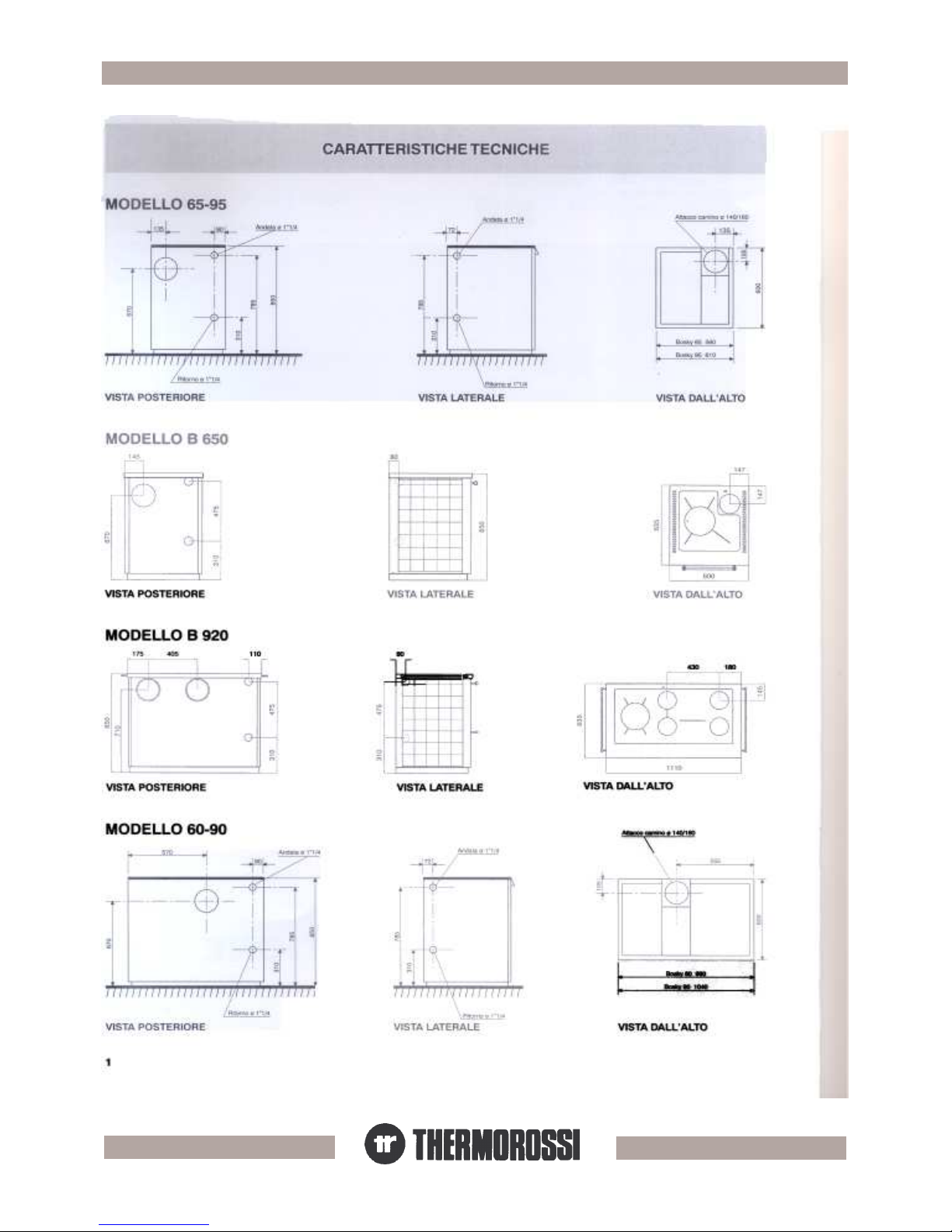
Key
Flue outlet
connection
Delivery
Return
Thermal
discharge
Legenda
Attacco
Camino
Andata
Ritorno
Scarico
termico
pg. 5
Key
Flue outlet
connection
Delivery
Return
Thermal
discharge
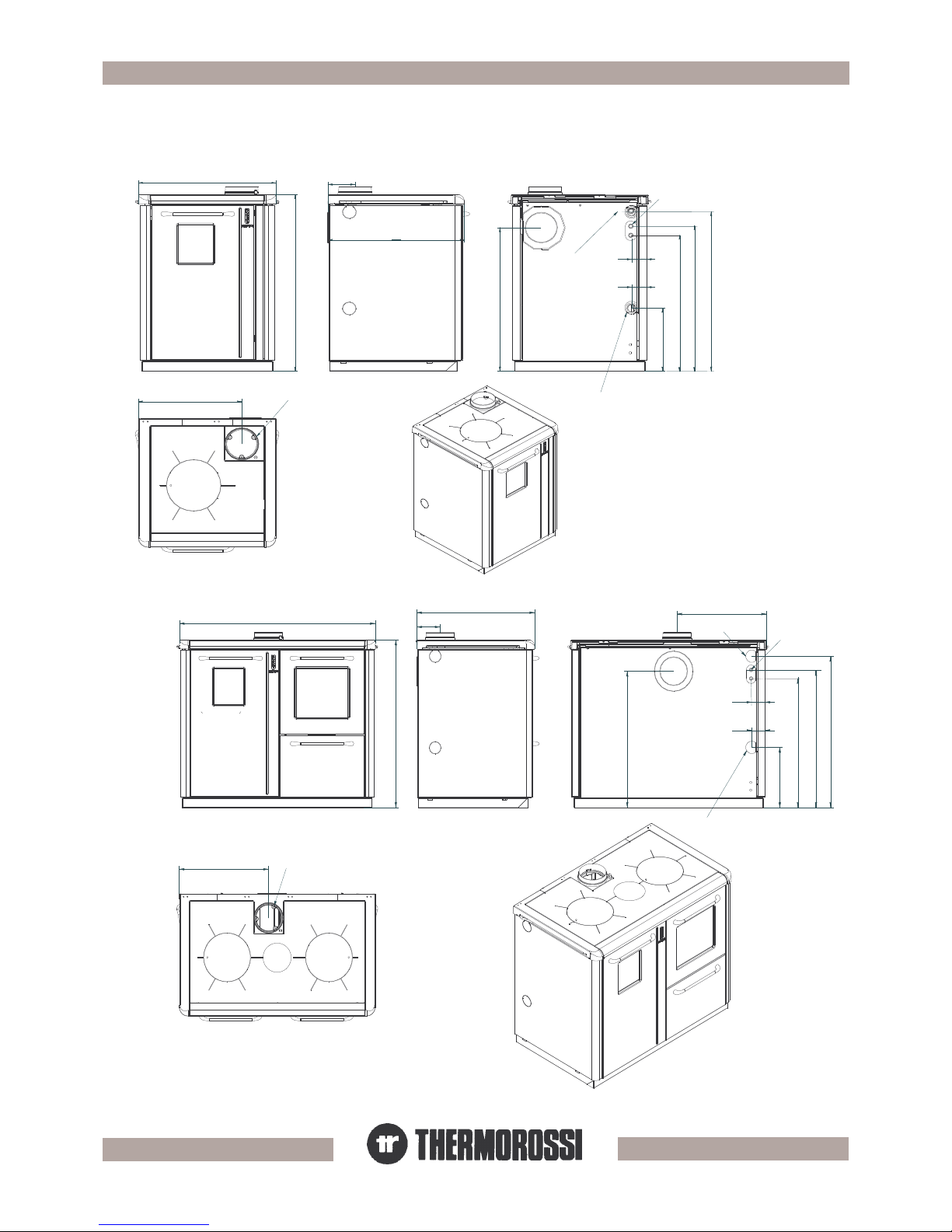
Model
Rear view
Side view
View from
above
Technical
Characteristics
Legenda
Attacco
Camino
Andata
Ritorno
Scarico
termico
Modello
Vista posteriore
Vista laterale
Vista dall'alto
Caratteristiche
tecniche

pg. 6
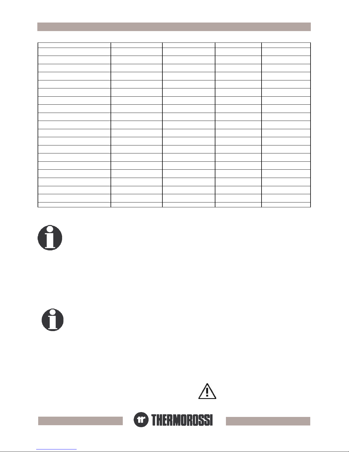
ATADLACINHCET ATADLACINHCET
ATADLACINHCET
ATADLACINHCET ATADLACINHCET 029YKSOB 029YKSOB
029YKSOB
029YKSOB 029YKSOB 06YKSOB 06YKSOB
06YKSOB
06YKSOB 06YKSOB 09YKSOB 09YKSOB
09YKSOB
09YKSOB 09YKSOB
WkyticapacxoberiF
6,92 3,52 6,92
WkyticapaclufesU
4,42 9,02 4,42
potkoocmorfnoitaidartaeH
Wk
7 7 7
mmhtdiW
0111 099 0401
mmhtpeD
536 006 006
mmthgieH
058 058 058
mm.midgninepodeeF
481Lx261H 481Lx261H 481Lx261H
mmxamhtdiwxoberiF
003 052 003
mmxamhtpedxoberiF
244 244 244
mmxamthgiehxoberiF
535 535 535
mmhtdiwnevO
063 063 063
mmhtpednevO
035 035 035
mmthgiehnevO
023 023 023
mm.midpotkooC
074x079 005x009 005x059
mm.DteltuoeulF
051 051 051
.thgiehteltuoekomsraeR
mm
017 076 076
.DsnoitcennocgnitaeH
4/1"1 4/1"1 4/1"1
tltnetnocydobrelioB
52 02 52
mmyenmihcybderiuqer.caV
nmulocretaw
.
2- 2- 2-
gKhgiewlatoT
592 062 572
ATADLACINHCET ATADLACINHCET
ATADLACINHCET
ATADLACINHCET ATADLACINHCET 056YKSOB 056YKSOB
056YKSOB
056YKSOB 056YKSOB 56YKSOB 56YKSOB
56YKSOB
56YKSOB 56YKSOB 59YKSOB 59YKSOB
59YKSOB
59YKSOB 59YKSOB
WkyticapacxoberiF
3,52 3,52 6,92
WkyticapaclufesU
9,02 9,02 4,42
potkoocmorfnoitaidartaeH
Wk
5 5 5
mmhtdiW
006 065 016
mmhtpeD
536 006 006
mmthgieH
058 058 058
mm.midgninepodeeF
481LX261H 481LX261H 481LX261H
mmxamhtdiwxoberiF
052 052 003
mmxamhtpedxoberiF
244 244 244
mmxamthgiehxoberiF
535 535 535
mmhtdiwnevO
- - -
mmhtpednevO
- - -
mmthgiehnevO
- - -
mm.midpotkooC
084X025 084X025 035X025
mm.DteltuoeulF
051 051 051
.thgiehteltuoekomsraeR
mm
076 076 076
.DsnoitcennocgnitaeH
4/1"1 4/1"1 4/1"1
tltnetnocydobrelioB
02 02 52
mmyenmihcybderiuqer.caV
nmulocretaw
.
2- 2- 2-
gKhgiewlatoT
791 281 091
pg. 7
33
33
3
GENERAL DESCRIPTIONGENERAL DESCRIPTION
GENERAL DESCRIPTIONGENERAL DESCRIPTION
GENERAL DESCRIPTION
3.13.1
3.13.1
3.1
OPERAOPERA
OPERAOPERA
OPERA
TING PRINCIPLETING PRINCIPLE
TING PRINCIPLETING PRINCIPLE
TING PRINCIPLE
•Your central heating cooker has been constructed to satisfy in full all your heating and practical needs.
3.23.2
3.23.2
3.2
THE FUELTHE FUEL
THE FUELTHE FUEL
THE FUEL
Special attention must be given to the characteristics of the wood: like all biomass generators. The good
performance of the generator depends on the type of wood used and on its degree of seasoning.
The recommended fuel is normal wood having a moisture content of 10-20% and a thermal value of 2500-3500 Kcal/Kg. Using the right fuel, and
knowing which is in fact the most appropriate wood to use, is one of the most important aspects concerning the use of your central heating
cooker in order to prevent damaging it and the flue outlet.
All types of solid fuel are suitable but we recommend using only hard and well-seasoned wood.
We advise against using wet wood or wood that has been seasoned for less than 18/20 months, as it can cause malfunctions and the formation
of tarry deposits, as well as not giving the correct thermal performance. All woods have different heat outputs: for example, 1Kg of beech equals
1.15Kg of birch, 1.6 Kg of fir, 0.5 Kg of briquettes… The heat outputs can also vary considerably depending on the type of fuel used and on the
size of the piece of wood. Using pieces of wood that are too thick cannot guarantee the declared power yield. Do not burn generic waste or
plastic but above all never use petrol or other inflammable liquids. When using briquettes it is mandatory to halve the fuel consumption.
The use of fuel that does not conform to the specifications set out
above immediately invalidates the warranty on the central heating
cooker.
ATADLACINHCET ATADLACINHCET
ATADLACINHCET
ATADLACINHCET ATADLACINHCET 52FYKSOB 52FYKSOB
52FYKSOB
52FYKSOB 52FYKSOB 03FYKSOB 03FYKSOB
03FYKSOB
03FYKSOB 03FYKSOB 52YKSOB 52YKSOB
52YKSOB
52YKSOB 52YKSOB 03YKSOB 03YKSOB
03YKSOB
03YKSOB 03YKSOB
WkyticapacxoberiF
3,52 6,92 3,52
6,92
WkyticapaclufesU
9,02 4,42 9,02
4,42
WkpotmorfnoitaidartaeH
7 7 5
5
mmhtdiW
5501 5501 246
246
mmhtpeD
636 636 636
636
thgieH
mm
968 968 968
968
mm.midgninepodeeF
532x012 532x012 532x012
532x012
mmxamhtdiwxoberiF
003 003 003
003
mmxamhtpedxoberiF
244 244 244
244
mmxamthgiehxoberiF
045 045 045
045
mmhtdiwnevO
063 063 -
-
mmhtpednevO
055 055 -
-
mmthgiehnevO
023 023 -
-
mm.midpotkooC
525x249 525x249 525x525
525x525
mm.DteltuoeulF
051 051 051
051
thgiehteltuoekomsraeR
mm
707 707 707
707
.DsnoitcennocgnitaeH
4/1"1 4/1"1 4/1"1
4/1"1
ltnetnocydobrelioB
72 72 72
72
mmyenmihcybderiuqer.peD
.nmulocretaw
2- 2- 2-
2-
gKthgiewlatoT
403 403 122 122
2.12.1
2.12.1
2.1
VITRIFICAVITRIFICA
VITRIFICAVITRIFICA
VITRIFICA
TIONTION
TIONTION
TION
The central heating cookers series 25 - 30 - F25 - F30 - 60 - 65 - 90 - 95 can be supplied boiler body with vitrification
treatment. This treatment occurs at very high temperatures that permit the glass and steel to melt into an alloy
that is completely impervious to corrosion attack caused by acid combustion smoke. Vitrification protects the
boiler body from corrosion caused by acid smoke and condensation developed by the combustion of the wood
fuel. The presence of surface defects such as indents, scratches, etc..., do not affect the life or resistance of the
corrosion proofing treatment.
pg. 8
44
44
4
INSTINST
INSTINST
INST
ALLAALLA
ALLAALLA
ALLA
TIONTION
TIONTION
TION
4.1 L4.1 L
4.1 L4.1 L
4.1 L
OCAOCA
OCAOCA
OCA
TING TING
TING TING
TING
THE CENTRAL HEATHE CENTRAL HEA
THE CENTRAL HEATHE CENTRAL HEA
THE CENTRAL HEA
TING COOKERTING COOKER
TING COOKERTING COOKER
TING COOKER
4.1.1 INSET CENTRAL HEA4.1.1 INSET CENTRAL HEA
4.1.1 INSET CENTRAL HEA4.1.1 INSET CENTRAL HEA
4.1.1 INSET CENTRAL HEA
TING COOKERTING COOKER
TING COOKERTING COOKER
TING COOKER
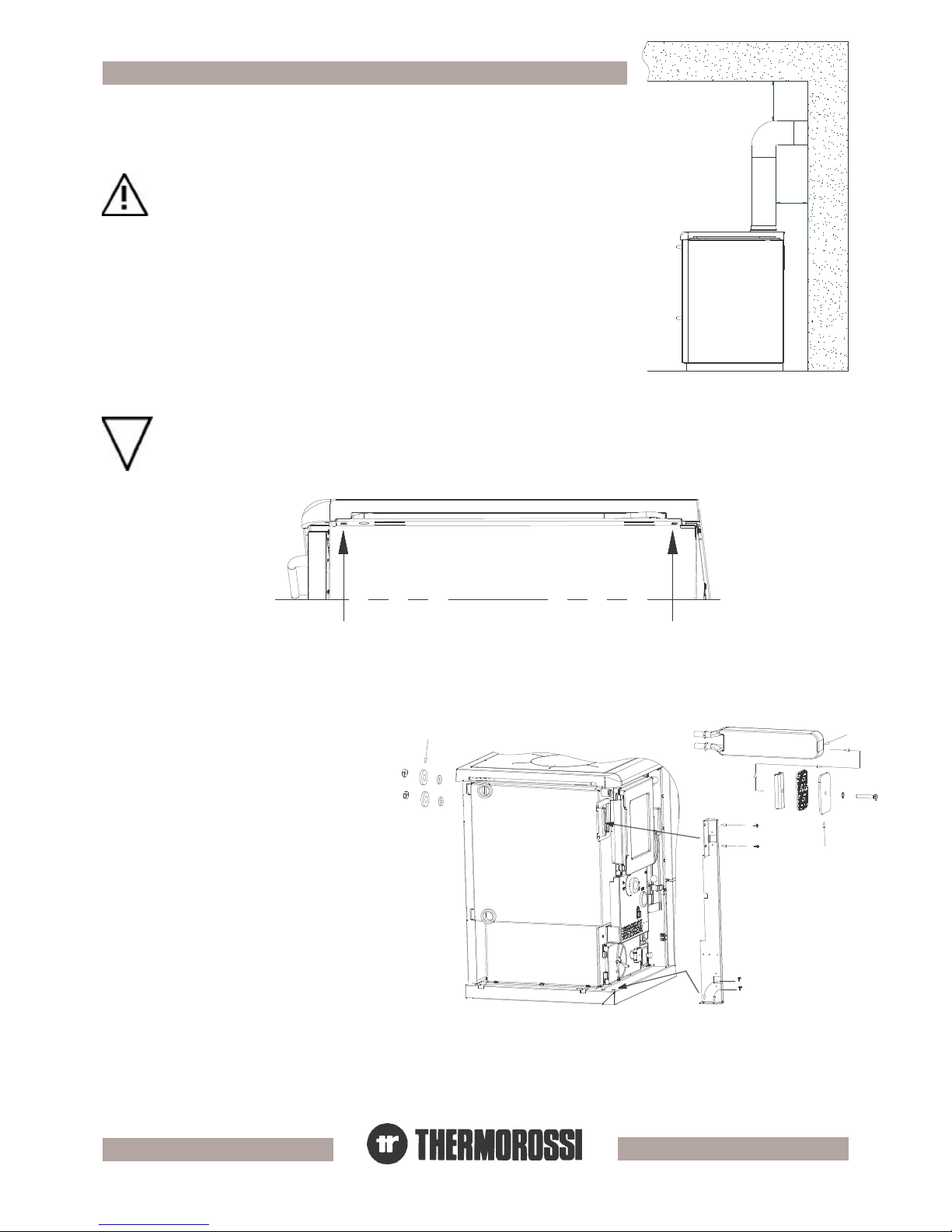
To install the safety heat exchanger remove the
vertical door, the left side together with its
insulation and the vertical upright that holds the
door together with its screws as indicated.
Slide in the heat exchanger (1) and secure it to
the boiler using the hardware (2) provided.
Close the hole with the plug (3). By installing a
thermal relief valve the excess heat is absorbed
as soon as the central heating cooker rises to
excessive temperature values due to external
causes. This function is called fast disconnection
phase.
450 mm se
parete in legno
450 mm se
soffitto in legno
soffitto in muratura
250 mm se
450 mm for a timber ceiling
250 mm for a masonry ceiling
450 mm for a
timber wall
4.24.2
4.24.2
4.2
MOUNTING MOUNTING
MOUNTING MOUNTING
MOUNTING
THE SAFETY HEATHE SAFETY HEA
THE SAFETY HEATHE SAFETY HEA
THE SAFETY HEA
T EXT EX
T EXT EX
T EX
CHANGERCHANGER
CHANGERCHANGER
CHANGER
(OPTION(OPTION
(OPTION(OPTION
(OPTION
AL) (ONLAL) (ONL
AL) (ONLAL) (ONL
AL) (ONL
Y FOR 25 - 30 - F25 - F30)Y FOR 25 - 30 - F25 - F30)
Y FOR 25 - 30 - F25 - F30)Y FOR 25 - 30 - F25 - F30)
Y FOR 25 - 30 - F25 - F30)
A vital aspect to consider is that the flooring of the room in which the central
heating cooker is installed must be capable of bearing the weight of the
central heating cooker.
CAUTION: The room in which the central heating cooker is installed must be
adequately ventilated (1300 m3/h). Ensure that there is always a minimum
75mm safety gap between the central heating cooker and walls or
combustable materials. If inflammable items are positioned near the central
heating cooker (matchboarding, furniture, curtains, wall hangings, sofas,
etc...), this gap must be increased considerably. Adhere to the recommended
minimum distances illustrated in the drawing on the right. It is permissible to
install the heater near materials that are sensitive to heat as long as suitable
insulating protection is placed between the material and the heater (ref. UNI
10683).
For inset installations ensure that the top cast iron cornice is insulated from the surrounding
furnishings by means of lateral air spaces or compressed vermiculite insullation board
If you wish to integrate your central heating cooker with your kitchen furnishings or with a particular furnishing arrangement
remove the fold-away towel rack by undoing the 2 screws as illustrated in the figure below and then mount the enamelled
casing (only for models 25 - 30 - F25 - F30 ) . It is also advisable to apply 75mm spacers to the sides of the central heating
cooker to prevent the heat from the top cast iron cornice from damaging the adjacent furniture.
pg. 9
4.4 4.4
4.4 4.4
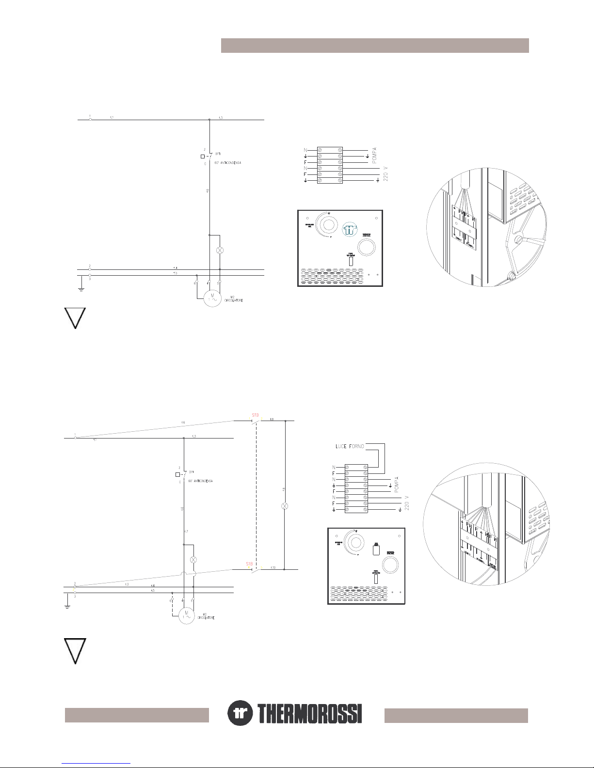
4.4 WIRING DIAGRAM F25 - F30
The electrical connections must be made before mounting the left side panel as the terminal block is located behind the
left side panel (see the figure below on the right).
CAUTION: IT IS MANDATORY TO EARTH THE CENTRAL HEATING COOKER AS ILLUSTRATED IN THE ABOVE DIAGRAM. IF
THIS INSTRUCTION IS NOT OBSERVED SERIOUS DAMAGE, WHICH IS NOT COVERED BY WARRANTY, WILL RESULT TO THE
BODY OF THE CENTRAL HEATING COOKER. HAVE AN ELECTRICIAN CHECK THE EARTHING. THERE MUST BE NO ELECTRIC
POTENTIAL (VOLTS) BETWEEN THE EARTH OF THE CENTRAL HEATING COOKER EARTH AND THE ACTUAL EARTH OF THE
PLANT.
CAUTION: IT IS MANDATORY TO EARTH THE CENTRAL HEATING COOKER AS ILLUSTRATED IN THE ABOVE DIAGRAM. IF
THIS INSTRUCTION IS NOT OBSERVED SERIOUS DAMAGE, WHICH IS NOT COVERED BY WARRANTY, WILL RESULT TO THE
BODY OF THE CENTRAL HEATING COOKER. HAVE AN ELECTRICAIN CHECK THE EARTHING. THERE MUST BE NO ELECTRIC
POTENTIAL (VOLTS) BETWEEN THE EARTH OF THE CENTRAL HEATING COOKER EARTH AND THE ACTUAL EARTH OF THE
PLANT.
The electrical connections must be made before mounting the left side panel as the terminal block is located behind the
left side panel (see the figure below on the right).
4.3 4.3
4.3 4.3
4.3 WIRING DIAGRAM 25 - 30
Key
pump
circulating pump
anticondensation thermostat
Key
pump
circulating pump
anticondensation
thermostat
oven light
Legenda
pompa
circolatore
anticondensa
Legenda
pompa
circolatore
anticondensa
luce forno
pg. 10
4.5 4.5
4.5 4.5
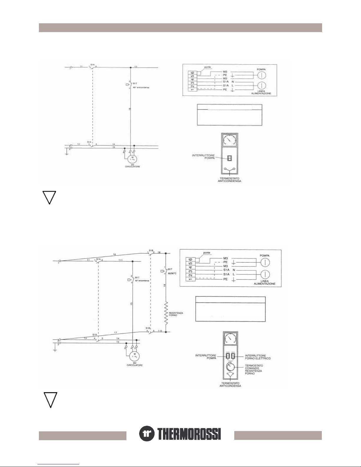
4.5 WIRING DIAGRAM 60 - 65 - 90 - 95 - 650 - 920 WITHOUT ELECTRIC OVEN
4.6 4.6
4.6 4.6
4.6 WIRING DIAGRAM 60 - 65 - 90 - 95 - 650 - 920 WITH ELECTRIC OVEN
CAUTION: IT IS MANDATORY TO EARTH THE CENTRAL HEATING COOKER AS ILLUSTRATED IN THE ABOVE DIAGRAM.
IF THIS INSTRUCTION IS NOT OBSERVED SERIOUS DAMAGE, WHICH IS NOT COVERED BY WARRANTY, WILL RESULT TO
THE BODY OF THE CENTRAL HEATING COOKER. HAVE AN ELECTRICAIN CHECK THE EARTHING. THERE MUST BE NO
ELECTRIC POTENTIAL (VOLTS) BETWEEN THE EARTH OF THE CENTRAL HEATING COOKER EARTH AND THE ACTUAL
EARTH OF THE PLANT.
Connect the wiring to the terminal block located in the left side.
Connect the wiring to the terminal block located in the left side.
PUMP CONNECTION
Connect the pump to terminals no. 4 and 5
and make a bridge connection for terminals
no. 5 and 6
Key
pump
pump
switch
bridge
power
line
circulating
pump
anticondensation
thermostat
anticondensation
thermostat
PUMP CONNECTION
Connect the pump to terminals no. 4 and 5
and make a bridge connection for terminals
no. 5 and 6
CAUTION: IT IS MANDATORY TO EARTH THE CENTRAL HEATING COOKER AS ILLUSTRATED IN THE ABOVE DIAGRAM.
IF THIS INSTRUCTION IS NOT OBSERVED SERIOUS DAMAGE, WHICH IS NOT COVERED BY WARRANTY, WILL RESULT TO
THE BODY OF THE CENTRAL HEATING COOKER. HAVE AN ELECTRICAIN CHECK THE EARTHING. THERE MUST BE NO
ELECTRIC POTENTIAL (VOLTS) BETWEEN THE EARTH OF THE CENTRAL HEATING COOKER EARTH AND THE ACTUAL
EARTH OF THE PLANT.
KEY
pump
pump switch
bridge
power line
oven heating
element
power line
circulating pump
electric oven
switch
anticondensation
thermostat
oven element
control thermostat
Legenda
pompa
interruttore
pompa
ponte
linea
alimentazione
circolatore
anticondensa
termostato
anticondensa
Legenda
pompa
interruttore pompa
ponte
linea alimentazione
resistenza
forno
linea alimentazione
circolatore
interruttore forno
elettrico
termostato
anticondensa
termostato comando
resistenza forno
 Loading...