

THERMOROSSI BOSKY CHEF Fiori, BOSKY CHEF-F Fiori, BOSKY CHEF Vintage, BOSKY CHEF-F Vintage Installation, User & Service Manual
Page 1
1
THERMOROSSI
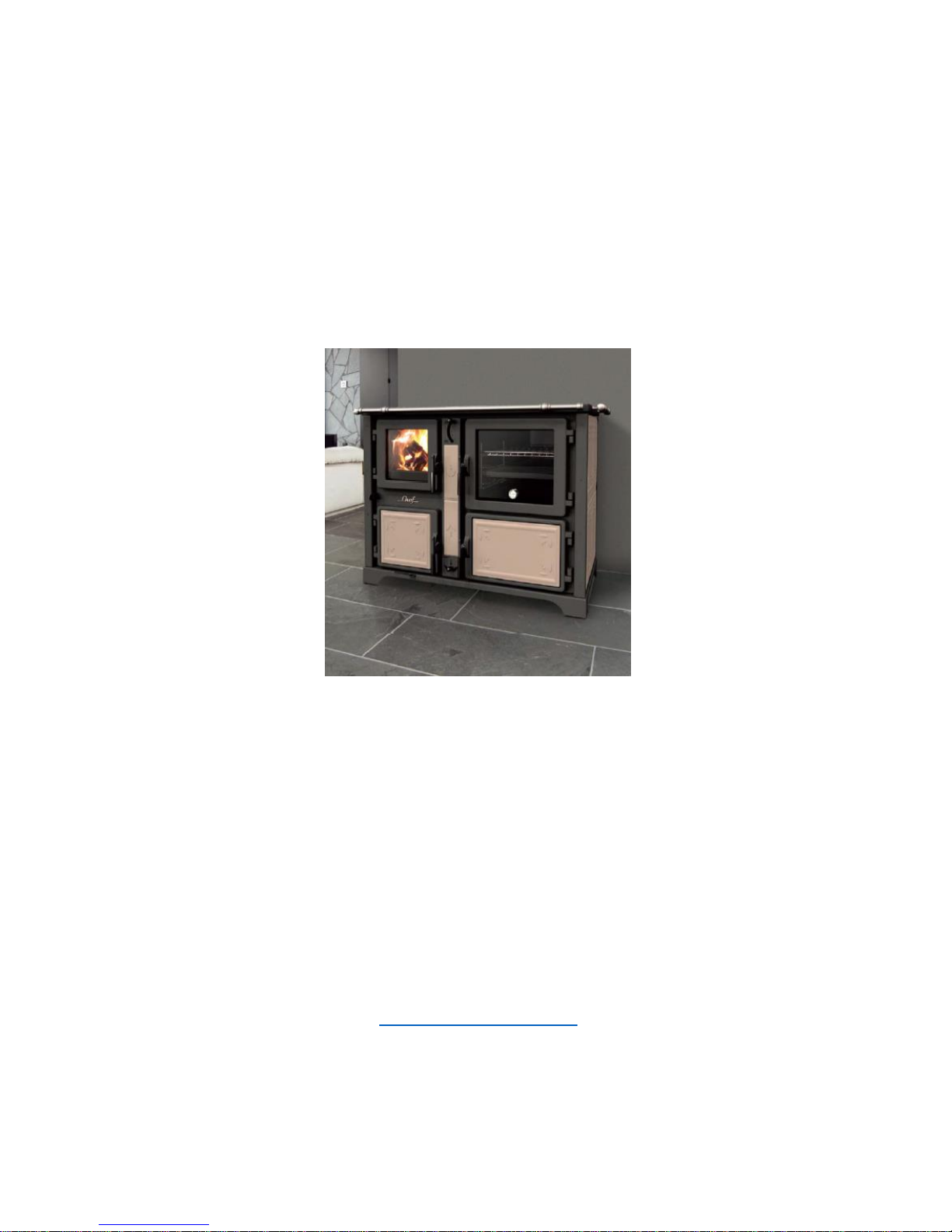
CHEF, CHEF F
INSTALLATION, USER &
SERVICE MANUAL
VER 1 10/2015
THERMOROSSI UK, BLYTH ROAD, HARWORTH, DONCASTER UK DN11 8NE -
tel. (0044) 1302742520 fax 01302 750573
EMAIL - technical@thermorossi.co.uk
www.thermorossi.co.uk
Page 2

2
C O N T E N T S
DECLARATION OF CONFORMITY
1. INTRODUCTION ...................................................................................................................................
1.1 General guidelines...................................................................................................................................
1.2 Safety guidelines .....................................................................................................................................
1.3 Standards and recommendations ...................................................................................................
1.4 Transport and storage .............................................................................................................................
2. TECHNICAL CHARACTERISTICS .........................................................................................................
3. GENERAL DESCRIPTION.........................................................................................................
3.1 Operating principle ..........................................................................................................................
3.2 Wood fuel............................................................................................................................................
4. INSTALLATION ......................................................................................................................................
4.1 Locating your cooker. ...........................................................................................................
4.2 ............................................................................................................
4.3 Installation of casing for Chef & Chef F. .................................................................
5. OPERATION ..........................................................................................................................................
5.1 Description of parts and main controls of the chef & chef F ...........................................
5.2 Lighting and starting the cookers ............................................................................................................
5.3 Operation of the cookers .......................................................................................................................
5.4 How to use the oven in cookers
6. CLEANING AND MAINTENANCE .........................................................................................................
6.1 General cleaning.....................................................................................................................................
6.2 Ash ............................................................................................................................................
6.3 How to clean the hot plate ....................................................................................................................
Recommendations ............................................................................................................................
7. Flue…………………….......................................................................................................................
7.1 General. ............................................................................................................................................
7.2 Essential requirements for the chimney cap ...................................................................................
7.3 Ventilation of the rooms ................................................................................................................
7.4 Connection with the flue outlet...............................................................................................................
8. TROUBLESHOOTING .....................................................................................................
9. Problems, causes and remedies for chef, chef F cookers .......................................................
10. SPARE PARTS ......................................................................................................................................
Page 3
3
DICHIARAZIONE DI CONFORMITA'
DECLARATION OF CONFORMITY
La THERMOROSSI S.P.A., VIA GRUMOLO N° 4 36011 ARSIERO (VI), sotto la sua esclusiva
responsabilità DICHIARA che l’apparecchiatura descritta in appresso: DECLARES that the product:
Descrizione
Description
Cucina a legna
Wood Cooker
Marchio
Trademark
THERMOROSSI
S.P.A.
DICHIARAZIONE DI PRESTAZIONE
DECLARATION OF PERFORMANCE
Dichiarazione di prestazione in accordo con il Regolamento (UE)
EN.12815-2001 Declaration of performance according to Regulation
(EU) EN.12815-2001/A1.2004
Modelli Models
CHEF, CHEF F
Ultime due cifre dell’anno in cui è affissa la marcatura CE 11
Last two figures of the year of the CE marking
Luogo Arsiero
Place
Data 8 Novembre 2011
Date
Firma
Sign
THERMOROSSI S.p.A.
Page 4
4
1 INTRODUCTION
1.1 GENERAL GUIDELINES
This installation, use and maintenance guide is an integral and essential part of the product and must
be kept by the user. Before commencing with the installation, use and maintenance of the product,
carefully read all the instructions contained in this booklet. This appliance must only be used as
intended by the manufacturer. Any other use is considered incorrect and therefore hazardous;
consequently, the user shall be totally liable for the product if used improperly.
Installation, maintenance and repairs must be carried out by personnel with professional qualifications
and in compliance with current regulatory standards and in accordance with the instructions of the
manufacturer of the appliance. Use only original spare parts. Incorrect installation or poor
maintenance could injure or damage people, animals or things; in this case the manufacturer shall be
relieved of all responsibility. Before commencing any cleaning or maintenance operation ensure that
the appliance has been disconnected from the mains power supply by means of the main system
switch or some other disconnecting device installed upstream from the appliance. The product must
be installed in locations suitable for fire-fighting and furnished with all the services (power and outlets)
which the appliance requires for a correct and safe operation. If the appliance is sold or transferred to
another user ensure that the guide is handed over with it.
Thermorossi S.p.A. maintains the author’s rights on these service instructions. The information in this
booklet may not be reproduced or given to third parties or used for competitive purposes without the
appropriate authorization.
1.2 SAFETY GUIDELINES
PERSONAL INJURY
This safety symbol identifies important messages throughout the manual. When you come across this
symbol, read the following message carefully. Users of the cooker must adhere strictly to
the instructions to avoid serious injury.
DAMAGE TO PROPERTY
This safety symbol identifies messages or instructions that are essential for the correct
operation of the cooker and heating system. These guidelines must be observed to avoid
serious damage to both the cooker and the heating system.
INFORMATION
This safety symbol instructions are important for the good operation of the cooker/heating
system. The appliances will not function correctly if the instructions are not observed correctly.
1.3 STANDARDS AND RECOMMENDATIONS
•Normative references: national and international standards used as reference guides for the
design, industrialization and production of the products indicated in this manual
– European Directive 73/23/EEC – standard CEI 61/50
- European Directive 93/68/EEC – standard CEI EN 60204 – European Directive
89/336/EEC – standard CEI64-8 (IEC364) EN 12815 : 2001 , EN 12815 : 2001 / A1:2004
– RECOMMENDATIONS:
Before using the appliance, carefully read every section of this instruction manual as knowledge of
the information and the regulations contained in it are essential for a correct use of the appliance.
The entire operation concerning the connection of the electric panel must be carried out by expert
personnel; no responsibility will be accepted for damages, even to third parties, if the instructions for
installation, use and maintenance of the appliance are not followed scrupulously.
Modifications made to the appliance by the user or on his behalf, must be considered to be under his
complete responsibility.The user is responsible for all the operations required for the installation and
maintenance of the appliance before and during its use.
1.4 TRANSPORT AND STORAGEPackaging The products are packaged in a
wooden crateTransport and handling The cooker must be kept in a vertical position and moved
exclusively by means of trolleys; take particular care not to damage the glass components.Storage
The cooker must be stored in humid free environments sheltered from the weather; it is inadvisable to
store the cooker directly on the floor. Thought must be given to the flooring as damage cannot be
responsible to Thermorossi.
Page 5
5
Page 6
6
Page 7
7
The performance values are from two beech logs totalling 3.7kg where the calorific value was 15.953
kj/kg with a moisture content of 9%. Using wood with different specifications to this will directly effect
performance, efficiency, ash formation, glass cleanliness and general dirtiness..
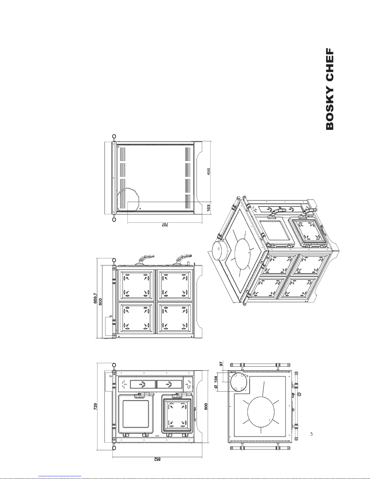
CHEF FIORI
CHEF F FIORI
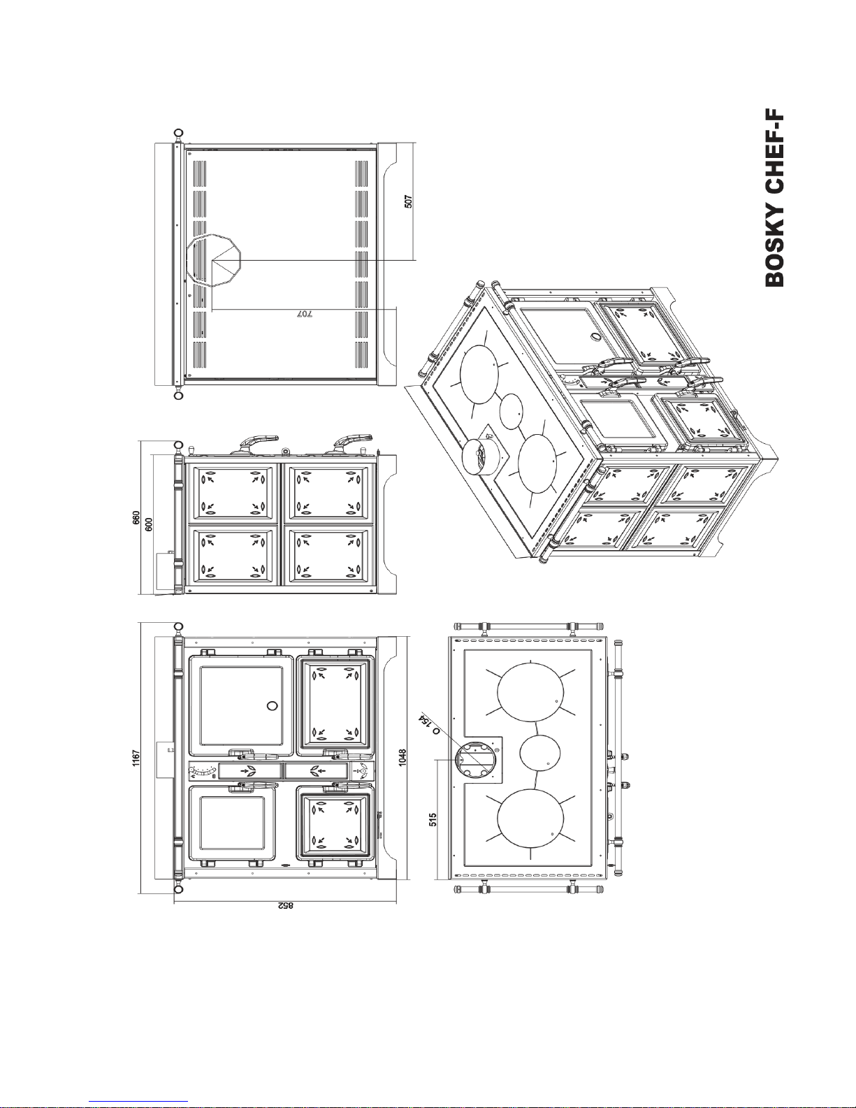
HEIGHT (mm)
852
852
DEPTH ( mm)
667
667
WIDTH ( mm)
600
1048
WEIGHT ( Kg )
247
330
FLUE DIAMETER ( mm)
Ø150
Ø150
MINIMUM FLUE DRAUGHT (Pa)
12
12
MAXIMUM POWER (kW )
16.4
16.4
MAXIMUM POWER (Btu)
56000
56000
NOMINAL POWER (KW)
12
12
NOMINAL POWER (Btu)
41000
41000
EFFICIENCY %
73.4
73.4
EMISSIONS CO (mg/m³ AT 13% O )
939.6
939.6
TOP OVEN DEPTH mm
515
TOP OVEN WIDTH mm
340
TOP OVEN HEIGHT mm
320
TOP OVEN CAPACITY LT
56
BOTTOM OVEN DEPTH mm
530
BOTTOM OVEN WIDTH mm
350
BOTTOM OVEN HEIGHT mm
200
BOTTOM OVEN CAPACITY LT
37
MAXIMUM ALLOWED FUEL PER HOUR KG
3.7
3.7
HOTPLATE DIMENSIONS MM
480 x 480
930 x 480
Page 8
8
The performance values are from two beech logs totalling 3.7kg where the calorific value was 15.953
kj/kg with a moisture content of 9%. Using wood with different specifications to this will directly effect
performance, efficiency, ash formation, glass cleanliness and general dirtiness..
CHEF VINTAGE
CHEF F VINTAGE
HEIGHT (mm)
852
852
DEPTH ( mm)
667
667
WIDTH ( mm)
680
1119
WEIGHT ( Kg )
251
332
FLUE DIAMETER ( mm)
Ø150
Ø150
MINIMUM FLUE DRAUGHT (Pa)
12
12
MAXIMUM POWER (kW )
16.4
16.4
MAXIMUM POWER (Btu)
56000
56000
NOMINAL POWER (KW)
12
12
NOMINAL POWER (Btu)
41000
41000
EFFICIENCY %
73.4
73.4
EMISSIONS CO (mg/m³ AT 13% O )
939.6
939.6
TOP OVEN DEPTH
515
TOP OVEN WIDTH
340
TOP OVEN HEIGHT
320
TOP OVEN CAPACITY LT
56
BOTTOM OVEN DEPTH
530
BOTTOM OVEN WIDTH
350
BOTTOM OVEN HEIGHT
200
BOTTOM OVEN CAPACITY LT
37
MAXIMUM ALLOWED FUEL PER HOUR KG
3.7
3.7
HOTPLATE DIMENSIONS MM
480 x 480
930 x 480
Page 9

9
GENERAL DESCRIPTION
3.1 OPERATING PRINCIPLE
•Your cooker has been constructed to satisfy in full all your cooking needs.
3.2 THE FUEL
CORRECT use of appliance when using wood fuel
For anyone interested in wood burning, there is much to learn; in the following text you will find
guidance and information on the subject.
Before installing or using a wood burning appliance, carefully read the installation procedure or if you
are in any doubt as to the soundness of your chimney, call us and we will be pleased to advise you.
ALL WORK MUST COMPLY WITH CURRENT BUILDING REGULATIONS or local applicable
legislation.
1-1 GOOD WOODBURNING TECHNIQUE
If wood is burned at high temperatures a more complete combustion occurs, complete combustion
means that most of the volatile hydrocarbons locked in the wood are released in the form of heat
generally displayed as long yellow flame combustion.
The higher the combustion chamber temperature, the more complete the combustion process.
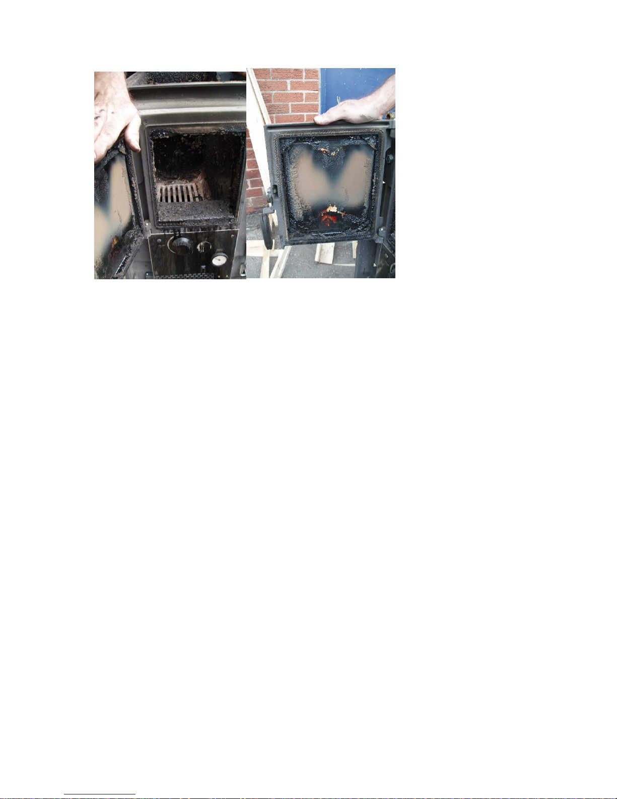
1-2 BAD WOOD BURNING technique
If wood is burned at low temperatures then very little is achieved and incomplete combustion occurs.
Incomplete combustion is typified by wood tar deposits all over the internals of the firebox, flue ways
and door glass.
The lower the combustion chamber temperature, the worse the combustion and the greater the build
up of wood tar.
In really bad cases, wood tar can drip from the appliance.
GOOD wood burning technique increases the efficiency of the burn process.
BAD wood burning technique decreases the efficiency of the burn process.
GOOD wood burning technique decreases your running costs.
BAD wood burning technique increases your running costs.
GOOD wood burning technique increases the life expectancy of the COOKER.
BAD wood burning technique decreases the life expectancy of the COOKER.
GOOD wood burning technique results in a clean appliance and chimney.
BAD wood burning technique results in a tar covered appliance and chimney.
Below is an example of tar build up that caused excessive damage when the chimney caught
fire – totally preventable!
Page 10
10
1-3 loading and running the appliance
The fire is ignited in the usual way and air is automatically admitted through the air inlet flap controlled
by the relevant setting of the thermostat knob.
When the fire is established, build it up slowly by adding a small quantity of wood, take care not to
put too much wood on at once otherwise this will :-
Kill the fire.
Reduce the firebox temperature.
Create smoke.
Cause tarring.
Cause condensation.
When the combustion chamber is up to a high enough temperature, the wood oil starts to vaporise
from the wood, and creates long yellow flames.
Secondary air is drawn in to mix with these flames and this further improves the combustion.
As the wood fuel burns away it slowly decomposes leaving a light grey coloured ash.
As is the case with all fires, if it is allowed to die down too much, it will not be possible to recover it.
Try to keep topping the firebox up regularly but do not overload it so as to kill the temperature of it.
If you need to keep the appliance in for longer periods of time try topping it up with smokeless fuel
otherwise let it go out and re light it.
If your wood has a moisture content above 25%, it would an idea to mix it with expensive kiln dried
wood (which is normally sub 10% moisture) to make sure the average burning is well below 20%
moisture.
Page 11

11
Do not burn general waste or various plastics, but above all never use gasoline or flammable liquids.
In the case of use of briquettes it is required to halve the fuel consumption.
2. ABOUT WOOD FUEL
2-1 Do I know how much wood I will need to burn?
Roughly 1 lb of wood equals 1Kw of energy; therefore if you need 10Kw of energy per hour you are
going to have to burn about 10 lbs of wood per hour.
Pine and Oak have different density therefore a tonne of Pine will take up substantially more volume
than a tonne of Oak.
If you work out how many Kilowatt hours are required to keep your property warm then you should be
able to work out the weight of wood required for a seasons heating.
2-2 Do I have a reliable and proven supplier of wood and do I know the cost?
Once you have established your seasons requirement you can order your supplies from a local wood
fuel supplier.
2-3 Do I know how to store the wood?
Before any wood is burnt, it should have a moisture content of no more that 20%.
This can be achieved by drying outdoors for 12 months and then under cover for the second 12
months assuming that the wood has been cut, split and stored in such a way as to allow adequate air
to circulate through the wood pile.
Ash is an exception to this rule as it can be cut early in the year and (providing it is stored correctly)
burned in the autumn.
2-4 equipment to help me get the best from my wood burning appliance
There are many factors which will affect the running of your wood burning appliance but the most
common problems are:-
WET WOOD
RUNNING THE APPLIANCE AT THE WRONG TEMPERATURE
INCORRECT INSTALATION
INCORRECT CHIMNEY
The main problem here is knowing
How do I know that the wood fuel is at the correct moisture content for burning?
How do I know if I am burning the wood at the correct temperature?
Page 12

12
Two pieces of equipment will help here, a moisture meter will tell you what the moisture content of
your wood is and a stove top thermometer will tell you what temperature your appliance is running at.
Both of these are available from us.
COAL
Firstly and most importantly we must say that you cannot burn coal on any appliance in a
smoke controlled area unless the appliance is specially designed and approved according to
statutory requirements.
If you wish to burn ordinary house coal on a chef or chef F you need to know how to do it, and that the
chef or chef F has the necessary design features. Do not use petrocoke as this will damage the
appliance.
The main problems are nearly always caused by: Putting too much coal on a fire which is almost out and then opening the ash pan door to increase the
draw.
Running the appliance at too low a temperature causing the fire to smoulder continuously.
Not riddling the fire often enough so preventing the required amount of combustion air reaching the
fire
If you put masses of coal on a low fire and then open the bottom ash access door, the result will be
that the fire will produce too much smoke which cannot burn or which when it bursts into flames will
cause a small explosion in the firebox and also up the chimney, the latter being particularly
dangerous.
The name of the game is to keep your fire burning healthily. Build it up with small amounts regularly
rather than large amounts infrequently and use coal no smaller than doubles. Cobbles are better
because they allow plenty of air to get around the firebox.
When loading the fire with a fresh change of coal, if it is possible rake the hot or glowing embers to
the front of the firebox and pout the new coal to the back. In this way the new coal will burst into
flames more quickly and the bright embers will encourage the smoke to ignite quickly.
Slack, shale, singles or small fuel will simply stop air getting through and cause the sooting and
exploding problems, which are to be avoided. Regular riddling is of prime importance, as mentioned
earlier.
If you get it wrong - you will normally do it in the first week or month. In some cases the result can be
a blocked chimney in less than a week. The part of the chimney, which blocks up first, will be the pipe
connecting the cooker to the chimney. This pipe must be as near vertical as possible for coal burning.
Rear outlet flues or bends are to be avoided at all costs, according to building regulations the
minimum angle a flue pipe can run is 45 dg., although we think a minimum of 60 dg is better.
Regular cleaning of the appliance and the chimney is essential the frequency of such cleaning would
be established by experience but we would think once every 6 weeks would be adequate.
Page 13
13
4 INSTALLATION
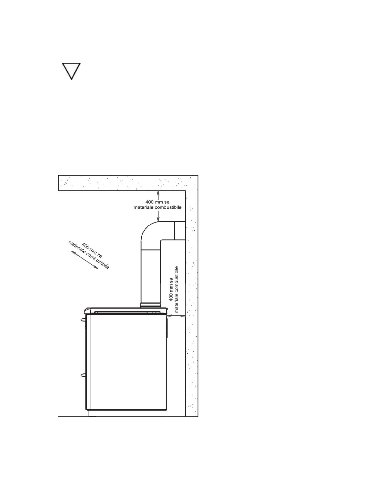
4.1 LOCATING THE COOKER
A vital aspect to consider is that the flooring of the room in which the cooker is installed
must be capable of bearing the weight of the cooker.
CAUTION: The room in which the cooker is installed must be adequately ventilated (1300 m3/h).
Ensure that there is always a minimum 75mm safety gap between the cooker and walls or
combustable materials. Inflammable items are positioned near the cooker (matchboarding,
furniture, curtains, wall hangings, sofas, etc...), this gap must be increased considerably. Adhere to
the recommended minimum distances illustrated in the drawing below. It is permissible to install the
heater near materials that are sensitive to heat as long as suitable insulating protection is placed
between the material and the heater (ref. UNI 10683).
For inset installations ensure that the top cast iron cornice is insulated from the surrounding
furnishings by means of lateral air spaces or compressed vermiculite insullation board
Page 14

14
4.13 mounting panels chef, chef F
After positioning the cooker proceed to mount the panels, as represented in the images below;
Proceed first to the fixing of ceramics ( 4 ) and ( 5 ) in their seats it is advisable to carry out
this operation by removing the doors themselves. Fix after degreased and dried both
ceramics and the seat, the same on the ceramic support with the thermal silicone supplied .
Before moving and reassembling the doors to the cooker you must wait at least 24 hours.
Remove profiles ( 2 ) and ( 1 ) .
Now proceed to the assembly of the lateral ceramics ( 3 ) assembling first the lower and then the
upper . Insert the ceramic ( 3 ) as shown in Figure 2 and Figure 3 first deforming the fins indicated
Page 15

15
Page 16

16
Provide for reassembling ceramics ( 6 ) by removing first the black knob of the smoke diverter and
then pulling the central support ceramics ( 8 ) by pulling on the inside ; later proceed through the use
of screws ( 7 ) to fixing the plate ( 6 ) on the support ( 8 ) . Finally fix the support ( 8 ) with the ceramic
to the cooker
4.13.2 Mounting side rails (OPTIONAL for chef, chef F)
In order to assemble the side handles (optional) you must assemble before mounting ceramics.
Proceed fixing of the spacers ( 2 ) and the supports ( 4) through the screws (3 ) . Now attach the group
created at the cooker through the screws ( 1 ) . Now align the supports ( 4 ) and insert the rail ( 7 ) .
Insert the rail end plugs ( 6 ) and fix the grub screws ( 5 )
Page 17

17
5 OPERATION
5.1.1 DESCRIPTION OF MAIN CONTROLS AND COMPONENTS OF CHEF, CHEF F
The main controls and components listed below are located on the enamelled door and
on the top surface.
A TOP FLUE EXIT
B REAR FLUE EXIT
C STARTER
D HOTPLATE RINGS - REMOVABLE
E OPTIONAL SIDE RAILS
F FRONT RAIL
G FIRE LOADING DOOR
H SECONDARY AIR REGULATION
I ASH PAN DOOR
L ASH PAN
M PRIMARY AIR REGULATOR
N SECONDARY ASH DOOR
O SECONDARY ASH PAN
P SPLASH BACK
CHEF F MODEL ONLY;
Q OVEN
R OVEN REGULATOR
S OVEN THEROMETER
T SECONDARY OVEN/WOOD DOOR
U COOKING VAPOUR EXIT VALVE
V UNDER OVEN CLEANING FLAP
Page 18

18
Page 19

19
Page 20

20
5.2 LIGHTING AND STARTING THE COOKERS
Before using the cooker make sure that all the movable parts are in position; also
remove any labels and stickers from the glass to avoid having permanent traces
remain on the surfaces
REMOVE THE PROTECTIVE ADHESIVE FILM FROM THE COOKTOP.
To start the cooker firstly activate the starter by lifting the pin until it hooks onto the plate by means
of the groove on it (see fig.below; use the tool provided). Leave the adjustment ring open. Now make
a small fire using paper or cardboard together with wood chips or small pieces of wood, and keep
adding bigger pieces of wood as the fire gets going. When the combustion is well underway, turn the
starter to the home position and close the adjustment ring.
CAUTION: DO NOT FORGET TO CLOSE THE ADJUSTMENT RING! IF IT IS LEFT
OPEN THERE IS A SERIOUS RISK OF THE COOKER OVERHEATING AND
SUBSEQUENTLY DAMAGING THE COOKER ITSELF. THIS DAMAGE IS NOT
COVERED BY WARRANTY AS IT WOULD BE THE RESULT OF NEGLIGENCE BY THE
USER. IF THE STARTER IS LEFT OPEN THE RESULT IS LESS HEAT TRANSFER TO THE
COOKER.
5.3 OPERATION OF THE COOKERS
The maximum thermal value is achieved by using fuel having a diameter of 5-7 cm , obviously bigger
pieces can be used but at the expense of less power.
Do not operate whilst leaving the firebox door open.
CAUTION : The wood load must always be suitable for the actual thermal absorption
requirements of the plant. Large firewood loads in limited absorption conditions result in the unburnt
wood remaining in the firebox for long periods of time. This situation encourages the distillation of the
wood resulting in the formation of large quantities of gases and vapours that are only partially burned.
The gases condense in the cooker and in the flue and create tarry deposits.
The hotplate rings can be lifted out to allow direct heat transfer (using the tool provided), this is the
style of Chinese cooking with woks placed on directly on flames, very hot and quick cooking follows.
Correctly choosing the right pans is obviously important.
The left handside of the hotplate being directly over the firebox is considerately hotter than the right,
so you can have boil, fry zone and a simmer zone at the same time.
5.5 HOW TO USE THE OVEN IN chef F
By using the smoke deviator flap (Drawing below) the cooker can have 2 operating modes:
-Lever upwards-Only heating hotplate above the firebox, in this mode the oven cannot be heated,
only the left side of the cook top plate is heated. In this operating mode the maximum heat output is
transferred to the hotplate, but there is some heat transfer to the oven to allow gentle heating
. –Lever downwards-Hotplate and oven, in this mode the oven can be heated, the entire cook top
plate is heated.
Page 21

21
Fig.4 Lever for secondary air
5 STOVE FUNCTION
When it turns on and start reacting to the regulation of primary and / or secondary air you can
increase or decrease the combustion adjusting the kitchen to the various needs of heating or cooking
. The useful power is reached using fuel as indicated in par.5.4 To rekindle the fire to free the slots
for the air from the ash to promote better combustion.
Page 22

22
6 CLEANING AND MAINTENANCE
6.1 GENERAL CLEANING
. Your cooker does not require any special maintenance; simply adhere to the simple and basic
but regular controls and general cleaning. This will guarantee regular operation and optimal
output at all times. As for all machines that run on solid fuel, the main enemy is undoubtedly the
dirt generated by ash, condensation, poor fuels; consequently it is important to clean the entire
cooker twice a year. The air inlets can be cleaned with an ordinary vacuum cleaner.
However, we recommend having the flue outlet cleaned by a professional chimney
sweep.
Caution: The glass and all the glazed steel parts must be cleaned with water
and a gentle detergent when the oven has cooled.
6.2 ASH
The cookers are fitted with 2 ash pans placed under the firebox base. To access the pans you need
to open the enamelled door of your cooker completely
We recommend emptying the ash pans (L and O) on a regular basis to prevent them from filling up
completely. It is necessary to regularly clean under the oven by opening the plug K. and vacuuming
the ash deposits . To ensure that your cooker performs efficiently it is advisable to regularly clean
the surfaces of the smoke passages towards the chimney, using the special equipment provided; to
access them remove the cook top plates X as illustrated in the drawing below. The tarry deposits
reduce the exchange and consequently the output as well.
Page 23

23
6.3 CLEANING THE HOT PLATES
Clean the hot plates with a normal gentle detergent. After cleaning (for the models with nonvitrified hot plate), protect the plate by applying a film of oil to keep it clean and shiny. As an
alternative to the oil apply a thin film of protective chrome paste (readily available from your
local hardware store). Take care when applying the paste not to indelibly dirty the cast iron
side cornices. If you detect any rust use a lightly abrasive scouring pad to remove it and then
proceed to apply the protective oil or chrome paste.
6.5 RECOMMENDATIONS
-Every time you stoke the fire make sure the grate is not too deep in material. The air passage
through the firebox grate must always be unobstructed.
-Every 10 hours of operation at least or whenever necessary clean the ash pans G and P as
described in paragraph 6.2.
-Every 2 weeks or whenever necessary clean the internal surfaces of the oven and the door K under
the oven.
-Always ensure that the fuel fed into the firebox catches fire normally. Always ensure that this
occurs to prevent dangerous explosions in the firebox caused by the accumulation of unburnt
gases. If these explosions prove to be rather violent the manufacturer declines all responsibility for
the mechanical resistance of the glass and heater parts.
-Adhere strictly to the declared consumption:
consumption: max. 3.7 Kg / hour.
-Thoroughly clean the cooker and flue at least twice each season .
Warning it it normal for the hotplate area to deform approximately 3-4mm
Warning it will void the warranty if you load more than 3.7kg of wood per hour
Warning it is normal for the hotplate to discolour after the first lighting turning blue/yellow
Warning it is normal in the first few hours of use for there to be odours as material is burnt
off
Warning leave the oven door open for at least the first five hours of use
THERMOROSSI SPA DECLINES ALL RESPONSIBILITY FOR DAMAGES TO THINGS AND/OR
PERSONS CAUSED BY THE FAILURE TO OBSERVE THESE INSTRUCTIONS.
Page 24

24
7 FLUE
CHIMNEYS basics
An efficient wood burning stove is one of the most effective ways to improve the energy efficiency &
reduce the CO2 emissions in a house. To achieve its optimal performance an efficient appliance
needs an efficient chimney system. The key to a well performing chimney is consistent insulation
along the entire length of the flue without cold spots.
Vacuum .05” WG average.
Solid fuel appliances need class 1 chimneys which are designed to deal with flue gas temperatures
above 260 deg C.
Class 1 chimneys can be of lined, masonary construction or of prefabricated insulated metal
construction.
The job of the chimney is two fold-:
1. To safely remove the products of combustion (SMOKE)
2. To generate suck (VACUUM) to provide the fire with an adequate supply of air.
The power (DRAFT), (suck or vacuum the chimney can develop) depends upon the following-:
THE HEIGHT.
THE POSITION OF THE TERMINAL RELATIVE TO OTHER, LOCAL, OBJECTS
THE DIAMETER.
THE TEMPERATURE OF THE GASSES IN IT. (lining and insulation may come in to this)
THE RESISTANCE OF THE INNER SURFACE OF THE CHIMNEY.
THE AVAILABILITY OF ADEQUATE VENTILATION.
THE HEIGHT ABOVE SEA LEVEL
Any bend in any part of the chimney or roughness on the internal chimney wall will slow down the
velocity of rising gasses and reduce the effectiveness of the chimney.
Any slight reduction in the flue gas temperature will reduce the chimney vacuum or pull, hence when
the stove is slowed down for all night burning, as the flue gas cools down the chimney vacuum
reduces and as the chimney vacuum drops, the stove may well go out. This problem is highlighted
even more during very cold weather when the chimney can cool down even faster.
Minimum draft of 18/20 PASCAL 0.18/0.20 mBAR
BEWARE, no one can guarantee that a chimney will work even after relining has been carried out.
Check out your chimney, look around your locality at other chimneys to see if there is a localised
problem of down draughting.
If you have bought a house and have no experience as to the performance of the chimney be very
careful, ask the previous owners and try to gather as much information as possible before you commit
yourself.
As a rough rule of thumb consider that if you have a 90 bend in the flue you will need an additional 1m
of height and for every metre of horizontal flue you will need an additional 2m of height.
A chimney cap is a device that is normally placed on top of a flue outlet for the purpose of facilitating
dispersion of the combustion products; it must satisfy the following requirements;
-have a useful exhaust section that is at least double the section of the flue outlet on which it is
inserted;
-have a shape that prevents the entry of snow or rain into the flue outlet;
-be built in such a way that venting of the combustion products is guaranteed regardless of wind
direction. The diagrams show how the chimney should be constructed. A spinning cowl can be
effective of which we supply.
LINING OF EXISTING CHIMNEY’S
Most old, leaking chimneys need lining and insulating with special materials designed to:-
1. Cure Leaks.
2. Reduce the build up of tar and soot on the walls of the flue.
3. Withstand the tremendous heat generated when tar and soot catch fire.
4. Generate a steady and controlled flue vacuum.
Old unlined chimneys are not suitable, if wood burning appliances are used on these chimneys the
following may happen:
Tar builds up on the brick faces of the internal chimney walls.
Page 25

25
This build up can take from 12 months to 5 years, and as time passes the tar gets thicker and thicker,
in really bad cases the tar can work its way through the chimney walls into the plasterwork of
adjoining rooms staining the wallpaper or plaster and causing a pungent wood smoke smell which can
contaminate the affected rooms.
If a chimney in this state catches fire the results are severe causing bricks and mortar to crumble and
drop down the chimney, and tar to ouze through the affected walls.
Often, with a chimney fire of this nature it could well be necessary to remove the complete stack
taking out and replacing all the walls affected by the tar impingement.
Severe damage can also occur on some types of twin wall stainless steel chimneys, causing
distortion and leaks of flue gases.
CHIMNEY HEIGHTS AND TERMINAL POSITIONS
Fig 1 is a rough guide about chimney heights and terminal positions.
Many manufacturers will call for a minimum flue height of 4.5 meters.
Document J of the building regulations provides details of the required statutory flue heights and
terminal positions, the British Standard for chimney height calculations is BS5854:1980. (1996)
It would be illegal to install any appliance in a residential dwelling without complying with
Document J or the manufacturers instructions.
In the schematic shown in fig1 chimney locations are graded on a scale of 1 to 4
4. being the optimum position.
3. being the next
2. being not very good and likely to cause problems
1. Being not capable of complying with current legislation.
Note that the fig 1 illustration is not accurate and should only be used as a general guide.
Before any instalation work is carried out, accurate compliance with Doc J of the Building Regs should
be ensured.
Fig 1
Page 26

26
Page 27

27
Pre Fabricated Chimneys
FIG 2 Single Story Instalations INTERNAL
Page 28

28
FIG 3 TWO STORY INSTALATIONS INTERNAL
Page 29

29
7.3 CONNECTION TO THE CHIMNEY
The smoke outlet can be connected at the top of the hotplate or at the back of the cooker
using the hardware provided as illustrated in the figure below. If you wish to connect the
chimney to the back of the cooker then you need to close the top smoke outlet with the
cover provided, remove the perforated cover from the back and remove the fixed cover by
undoing the screws. Next connect the cast iron flue collar using the hardware provided.
There must be no narrowing of the pipes that connect the cooker to the flue outlet. The
joints must be completely airtight. The number of elbows used must be kept to a minimum.
Horizontal runs must be kept to a minimum and have a minimum slope of 4%. Never use
the same flue outlet for more than one appliance.
Page 30

30
7.4 VENTILATION OF THE ROOMS
It is essential for the room in which the appliance is installed to be well-ventilated, also to guarantee
secondary air for combustion in the cooker.
The natural air flow occurs directly through permanent apertures to the outside made in the walls of
the room, or by means of single or multiple ventilation ducting.
The ventilating air must come from outside and if possible, away from sources of pollution. Indirect
ventilation is also allowed by taking in air from rooms adjacent the one where the heater is installed
taking into account all the warnings and limitations specified below. •The apertures in the walls must
comply with the following requirements:
- -have an unobstructed section of at least 6cm² for each Kw of installed thermal power, with a
minimum limit of 100cm²;
- be made in such a way that the vent openings, both on the inside and outside of the wall, cannot be
obstructed;
- be protected with grills or similar systems in order not to reduce the section described above;- be
situated at floor-level.
The air flow can also be obtained from an adjacent room as long as:
- the adjacent room is equipped with direct ventilation in compliance with the points described above;
- in the room to be ventilated the installed appliances are only connected to one flue outlet;
- the adjacent room is not used as a bedroom or a common area of the building;
- the adjacent room is not a room with a fire hazard, such as storage sheds, garages, combustible
material store rooms, etc...;
- the adjacent room does not become a vacuum compared to the room to be ventilated due to an
opposite draught effect;
- the air flow from the adjacent room to the room to be ventilated is unobstructed through the
permanent apertures having an overall net section of no less than that indicated above. These
apertures can be obtained by enlarging the space between the door and the floor.
- Under Reg J in the UK, an air vent is not required for older properties built before about 2005.
Properties that have been ‘improved’ with extra insulation and draught proofing of windows and
doors do require a vent.
- If the chimney/cooker is to be fitted on an external wall the air supply can be taken straight
from the outside. A 5” (100mm) diameter hole needs to be drilled in the correct place, 138mm
above the hearth and the cooker ‘manifold/extension air pipe’ kit purchased and fitted. A
proprietary grille is supplied with the kit, if not used an air brick or non-closing vent should be fitted
to ensure the air supply is not blocked in any way.
- The manifold method of supplying air is always to be preferred as there will be no draught in
the room especially when the cooker is not in use.
- If the cooker is not on an outside wall or the direct air supply method cannot be used, an air
vent must be supplied in the room in which the cooker is fitted.
- The sizes of the vents required is: 1650mm sq. (50mm diam.)
- Only permanently open vents can be used and consideration should be given to draught
when the cooker is not in use. Site these vents carefully. The vent covers should comply with
Building Regulations Part J and should be sited where they cannot be blocked.
- Extractor Fans: These suck air out of the room and cause a negative pressure in the room so
they must have their own air vent to counter this. Even when the air is taken directly from the
outside using the manifold system a vent will be required for any extractor fan fitted in the same
room or adjacent rooms. Great care must be taken with restaurant/café kitchens which have
professional levels of extraction.
-
Page 31

31
8 TROUBLESHOOTING
8.1 PROBLEMS CAUSES AND REMEDIES FOR CHEF, CHEF F
Difficulty lighting the fire
Burner is clogged
Clean the burner by shifting the grate
to the winter position and riddle until
the ash drops through
wood is too high or
pieces too large
Use smaller pieces of firewood and
more seasoned firewood
Insufficient air in the
room
Create an adequate opening for air
inlet(see PARA. 7.4)
Poor draft
See causes -remedies "Poor draft"
(below)
Firewood has not yet
caught alight
Open the fire rekindling ring (para.
5.1) and wait for it to catch alight
Tendancy to generate condensation
(presence of humidity/water in the ash pan
and under the heater)
thermostat
Replace thermostat
Poor draught
See causes -remedies "Poor draft"
(below)
Smoke in the room.
Difficulty keeping the fire alight.
Difficulty reaching right oven temperature
Low temperature of cook top.
Flame insensitive to variations in draft.
Puffs of smoke while operating.
Soot deposits in hood.
Impossible to operate during the night (fuel
remains unburnt).
Poor draft
See causes -remedies "Poor draft"
(below)
Insufficient air in the
room
Create an adequate opening for air
inlet(see PARA. 7.4)
Oxidised cook top
Poor maintenance of the
cook top
para. 6.3
fuel burns too quickly).
Uncontrolled combustion.
Draft too strong
Reduce the draft by installing a
register in the chimney.
Difficulty in controlling the temperature.
Poor draft
Raise the flue outlet, install an
antidowndraft cap on the chimney
top.
Draft too strong
Reduce the draft by installing a
register in the chimney.
Page 32

32
Poor draft
Inspect the flue draft: Presence of
constrictions in the chimney, too
many curves, poor insulation;,section
too small / clean the flue outlet/ lift
the cook top and thoroughly clean
the smoke passage and in particular
the additional heat exchanger.
Puffs of smoke issue from the top of the
heater when the door is slammed shut.
Insufficient air in the
room
Create an adequate opening for air
inlet(see PARA. 7.4)
Variable draft
Raise the flue outlet, install an
antidowndraft cap on the chimney
top.
Variable combustion rhythm.
Good combustion only occasionally, almost
appears to depend on the wind conditions.
Insufficient air in the
room
Create an adequate opening for air
inlet
(see PARA. 7.4)
Page 33

33
9 SPARE PARTS
9.1 SPARE PARTS FOR BOSKY 25 - 30 (PART 1).
Legenda
Key
gomino
Rubber washer
Profile inox
Stainless steel strip
telaio
frame
Bianco
White
Canna fucile
Rifle barrel grey
Marron fumè
Smoky brown
Beige Beige
Rosso
Red
Vetro esterno
External glass
Vetro interno
Internal glass
Termometro
Thermometer
Page 34

34
Page 35

pg. 35
Page 36

pg. 36
Page 37

pg. 37
Page 38

pg. 38
Page 39

pg. 39
Page 40

pg. 40
Page 41

pg. 41
Page 42

pg. 42
Page 43

pg. 43
9.14 SPARE PARTS FOR BOSKY 25-30, COUNTRY (INSULATION COVERS ).
9.15 SPARE PARTS FOR BOSKY F25, F30 COUNTRY F (INSULATION COVERS).
 Loading...