

THERMOROSSI BOSKY 25, BOSKY F25, BOSKY 30, BOSKY F30, BOSKY COUNTRY Installation, User & Service Manual
...Page 1
THERMOROSSI
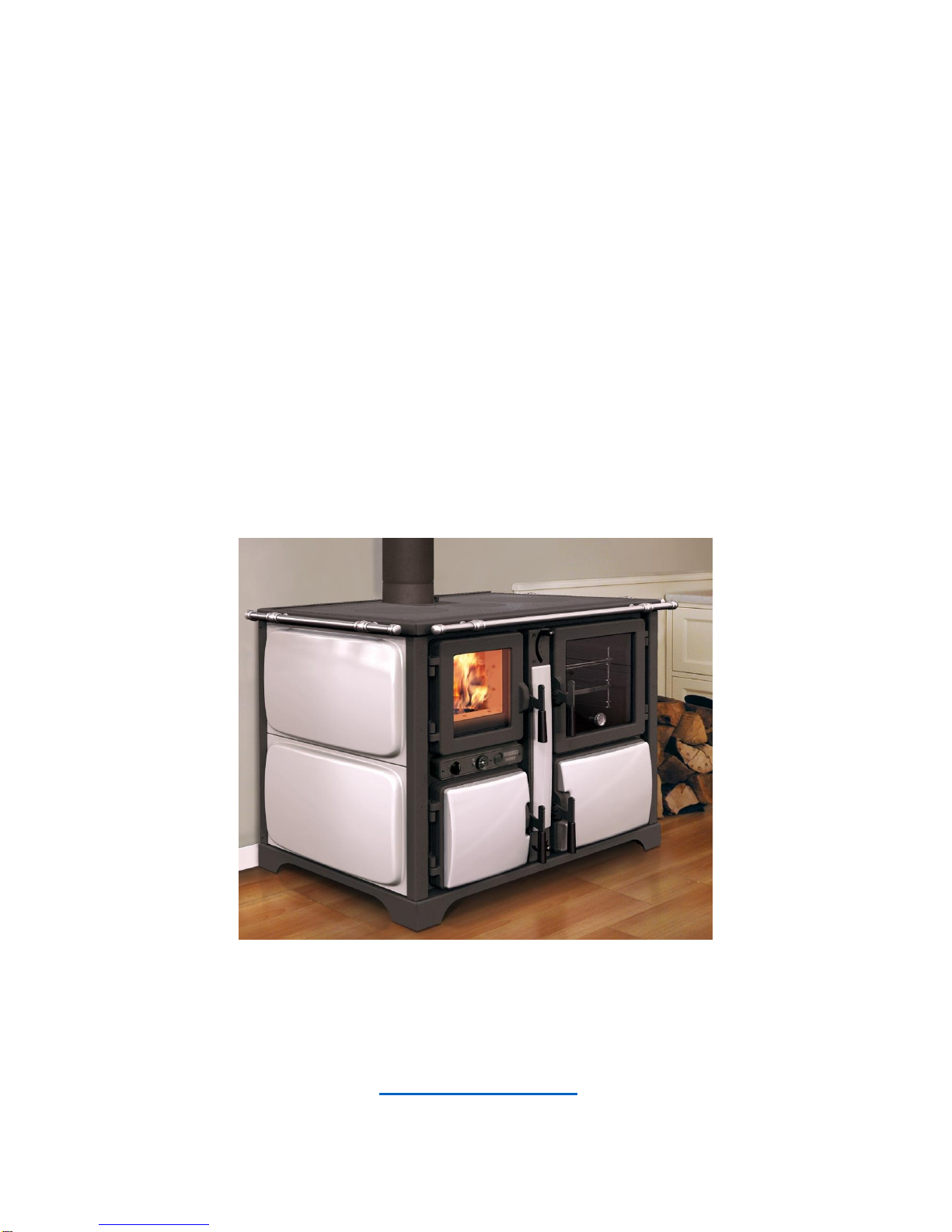
BOSKY 25,30 & F25, F30
COUNTRY, COUNTRY F
INSTALLATION, USER &
SERVICE MANUAL
VER 1 10/2015
THERMOROSSI UK,
BLYTH ROAD, HARWORTH, DONCASTER UK DN11 8NE
tel. (0044) 1302742520 fax 01302 750573
EMAIL - technical@thermorossi.co.uk
www.thermorossi.co.uk
Page 2

C O N T E N T S
DECLARATION OF CONFORMITY
1. INTRODUCTION .....................................................................................................
1.1 General guidelines.....................................................................................................
1.2 Safety guidelines .........................................................................................................
1.3 Standards and recommendations ...............................................................................
1.4 Transport and storage ..........................................................................................
2. TECHNICAL CHARACTERISTICS .............................................................................
3. Vitrification.....................................................................................................................
4. GENERAL DESCRIPTION..........................................................................................
4.1 Operating principle .....................................................................................................
4.2 Wood fuel.....................................................................................................................
5. INSTALLATION ..........................................................................................................
5.1 Locating your Bosky central heating cooker. ..............................................................
5.2 Installing the safety heat exchanger (only for 25 - 30 - F25 - F30 ) .......................
5.3 Wiring diagram 25 - 30. ...................................................................................
5.4 Wiring diagram F25 - F30. ........................................................................................
5.5 ......................................................................................................................................
5.6 Guidelines for the hydraulic connections of the central heating cooker to the boiler
coil…..............
5.7 Guidelines for the hydraulic connections of the central heating cooker to the boiler
tubes with interspacing ...................
5.8 Recommendations for the execution of the hydraulic and electric system
......................................
5.9 Installation of casing for Bosky 25-30-F25-F30. ..................................................
6. OPERATION ...............................................................................................................
6.1 Description of parts and main controls of the central heating cookers ........................
6.2 Lighting and starting the central heating cookers ................................................
6.3 Operation of the central heating cookers .....................................................................
6.4 Grate positions in the central heating cookers ....................................................
6.5 How to use the oven in central heating cookers F25-F30.............................................
6.6 The fold-away towel rack (only for 25 - 30 - F25 - F30 ) .............................................
7. CLEANING AND MAINTENANCE ...............................................................................
7.1 General cleaning..........................................................................................................
7.2 Ash ..............................................................................................................................
7.3 How to clean the hot plate ..........................................................................................
6.4 How to replace the oven light bulb ..............................................................
6.5 Recommendations ...................................................................................
8. FLUE ......................................................................................
8.1 General. .......................................................................................................................
8.2 Essential requirements for the chimney cap ...........................................................
Page 3

8.3 Ventilation of the rooms .........................................................................................
8.4 Connection with the flue outlet......................................................................................
9. TROUBLESHOOTING .................................................................................................
10. Problems, causes and remedies for Bosky central heating cookers ...........................
11. SPARE PARTS ...........................................................................................................
Page 4
9 RECOMMENDATIONS FOR THE EXECUTION OF THE HYDRAULIC AND ELECTRIC SYSTEM
Installation must be done by a competent person, namely HETAS H004 qualified.
Before installing your central heating cooker we recommend that your flue outlet has a suitable
draught.
We recommend connecting the plant circulating pump to the central heating cooker’s control
panel.
We recommend installing non-return valves to prevent natural circulation phenomena
between the central heating cooker and the plant (see drawing par. 4.5 - 4.6 - 4.7 - 4.8 ). The
presence of open boilers causes natural circulation on the water surface with subsequent
oxygenation of the water. The presence of natural circulation produces condensation and can
consequently cause corrosion to parts of the central heating cooker.
We recommend you earth the central heating cooker and check the efficiency of the earthing
of the electrical system to which the central heating cooker is connected.
We recommend a magnetic cleaning system to make sure system fluid is optimum for
maximising performance and lifespan of product
Water treatment equipment is needed when: mains water has a hardness higher than
100mg/ml, this can be checked with your local water supply company or if private supply you
will need to check its quality.
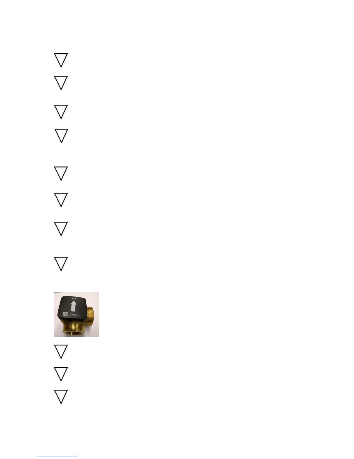
Fitting a 3 way mixing valve (see below) to minimise condensate corrosion is mandatory, this
ensures the return water going into boiler is above 55c which drastically reduces the quantity of
acidic corrosion and therefore increases the lifespan of the product.
Minimum water pressure of 0.2 bar is needed
The safety heat exchanger cannot be used to produce domestic hot water
The appliance cannot be used “dry” i.e. with no water in it.
Page 5

Care must be used when using a mixing system with alternative heat sources that do not allow
the bosky to be shut down which would cause the wood fuel to stew and cause multiple
problems such as mentioned in the fuel guide.
THERMOROSSI DECLINES ALL RESPONSIBILITY FOR THE CORRECT FUNCTIONING AND
DURATION OF THE APPLIANCE IF ALL OF THE ABOVE GUIDELINES ARE NOT
OBSERVED. NO TECHNICAL SERVICING BY OR ON BEHALF OF THERMOROSSI,
CAUSED BY THE NON-OBSERVANCE OF THESE RECOMMENDATIONS, WILL BE
COVERED BY WARRANTY.
Page 6
DICHIARAZIONE DI CONFORMITA
' DECLARATION OF CONFORMITY
La THERMOROSSI S.P.A., VIA GRUMOLO N° 4 36011 ARSIERO (VI), sotto la sua esclusiva responsabilità
DICHIARA che l’apparecchiatura descritta in appresso: DECLARES that the
product:
Descrizione Description
Cucina a legna Wood Cooker
Marchio Trademark
THERMOROSSI S.P.A.
Modelli Models
BOSKY COUNTRY
BOSKY COUNTRY – F
BOSKY 25
BOSKY F25
BOSKY 30
BOSKY F30
è conforme alle disposizioni legislative che traspongono le seguenti Direttive:
• 2004/108/CE (Direttiva EMC)
• 2006/95/CE (Direttiva Bassa tensione) •
• 2011/65/EU (Direttiva RoHS 2)
is in accordance with the following Directives: •
2004/108/EC Directive (EMC Directive)
• 2006/95/EC Directive (Low Voltage Directive) •
• 2011/65/EU Directive (RoHS 2)
e che sono state applicate tutte le norme e/o specifiche tecniche di
seguito indicate and that all the following standards have been applied
EN 55014-1 EN 60335-1 EN 50581
EN 55014-2 EN 60335-2-102
EN 61000-3-2 EN 62233
EN 61000-3-3
Ultime due cifre dell’anno in cui è affissa la marcatura CE 11
Last two figures of the year of the CE marking
Luogo Arsiero
Place
Data
Date
Firma
Sign
Page 7

DICHIARAZIONE DI PRESTAZIONE
DECLARATION OF PERFORMANCE
1/2
Dichiarazione di prestazione in accordo con il Regolamento (UE) 305/2011
Declaration of performance according to Regulation (EU) 305/2011
N° 20
Unique identification code of the product type:
1 BOSKY 25, apparecchio per il riscaldamento domestico, con acqua, alimentato a
ceppi di legna BOSKY 25, residential space heating appliance with water fired by wood logs
EN 12815:2001 A1:2004
Numero di tipo, lotto , serie o qualsiasi altro elemento che consenta l'identificazione del prodotto
da costruzione ai sensi dell'articolo 11, paragrafo 4:
2 Type, batch or serial number or any other element allowing identification of the
construction product as required under Article 11( 4):
BOSKY 25
Uso o usi previsti del prodotto da costruzione, conformemente alla relativa specifica tecnica
armonizzata, come previsto dal fabbricante:
Intended use or uses of the construction product, in accordance with the applicable
harmonised
3 technical specification, as foreseen by the manufacturer:
Apparecchio per il riscaldamento domestico, con acqua, alimentato a ceppi di legna
Residential space heating appliance with water fired by wood logs
Nome, denominazione commerciale registrata o marchio registrato e indirizzo del fabbricante
ai sensi dell'articolo 11, paragrafo 5:
4 Name, registered trade name or registered trade mark and contact address of the
manufacturer as required pursuant Article 11( 5):
THERMOROSSI S.P.A. Via Grumolo, n° 4 36011 Arsiero (VI)
Sistema o sistemi di valutazione e verifica della costanza della prestazione del prodotto da
costruzione di cui all'allegato V:
5 System or systems of assessment and verification of constancy of performance of the
construction product as set out in Annex V:
Sistema 3 e 4 / System 3and 4
Nel caso di una dichiarazione di prestazione relativa ad un prodotto da costruzione che rientra
nell'ambito di applicazione di una norma armonizzata:
In case of the declaration of performance concerning a construction product covered by a
harmonised standard:
6
L' organismo notificato KIWA ITALIA S.P.A. N° 0694 ha determinato il prodotto-tipo in
base a prove di tipo secondo il sistema 3 ed ha rilasciato il rapporto di prova 400238 The
notified laboratory KIWA ITALIA S.P.A. N° 0694 performed the determination of the
product type on the basis of type testing under system 3 and issued test report 400238
7
Page 8
La prestazione del prodotto di cui ai punti 1 e 2 è conforme alla prestazione dichiarata di cui al
punto 7. Si rilascia la presente dichiarazione di prestazione sotto la responsabilità esclusiva del
fabbricante di cui al punto 4
8
The performance of the product identified in points 1 and 2 is in conformity with the declared
performance in point 7. This declaration of performance is issued under the sole responsibility
of the manufacturer identified in point 4
Firmato a nome e per conto del fabbricante da
(nome e funzione)
Signed for and on behalf of the manufacturer
(name and title)
Luogo/Place Arsiero
Data/Date27/06/2013
Specifica tecnica armonizzata:
Harmonized technical specification:
EN 12815:2001 A1:2004
Caratteristiche Essenziali
Essential characteristics
Prestazione / Performance
Sicurezza antincendio / Fire safety
Reazione al fuoco / Reaction to fire
A1
Distanza da materiali combustibili
Distance to combustible materials
Minime distanze / Minimum distances (mm):
posteriore / rear = 200
lati / sides = 200 frontale
/ front = 800 soffitto /
ceiling = - pavimento /
floor = -
Rischio di fuoriuscita di braci incandescenti Risk
of burning fuel falling out
Passa / Pass
Emissione di prodotti della combustione
Emission of combustion products
CO 4692 ppm Alla potenza termica nominale / Nominal heat
output
Temperatura superficiale / Surface temperature
Passa / Pass
Sicurezza elettrica / Electrical safety
-
Pulizia / Cleanability
Passa / Pass
Pressione massima di esercizio Maximum
operating pressure
3 bar
Temperatura fumi a potenza termica nominale
Flue gas temperature at nominal heat output
T287 °C
Resistenza meccanica (per sopportare un camino/una
canna fumaria)
Mechanical resistance(to carry a chimney/flue)
NPD {Nessuna Prestazione Determinata}
Potenza termica nominale / Nominal heat output
21,00 kW
Potenza termica resa in ambiente / Room heating output
3,00 kW
Potenza termica ceduta all’acqua / Water heating output
18,00 kW
Rendimento
Efficiency
71,00 % Alla potenza termica nominale / Nominal heat output
Page 9

DICHIARAZIONE DI PRESTAZIONE
DECLARATION OF PERFORMANCE
1/2
Dichiarazione di prestazione in accordo con il Regolamento (UE) 305/2011
Declaration of performance according to Regulation (EU) 305/2011
N° 20B
Codice di identificazione unico del prodotto-tipo:
Unique identification code of the product type:
BOSKY F25, apparecchio per il riscaldamento domestico, con acqua, alimentato a ceppi
di
1 legna
BOSKY F25, residential space heating appliance with water fired by wood
logs EN 12815:2001 A1:2004
Numero di tipo, lotto , serie o qualsiasi altro elemento che consenta l'identificazione del
prodotto da costruzione ai sensi dell'articolo 11, paragrafo 4:
2 Type, batch or serial number or any other element allowing identification of
the construction product as required under Article 11( 4):
BOSKY F25
Uso o usi previsti del prodotto da costruzione, conformemente alla relativa specifica tecnica
armonizzata, come previsto dal fabbricante:
Intended use or uses of the construction product, in accordance with the applicable
harmonised
3 technical specification, as foreseen by the manufacturer:
Apparecchio per il riscaldamento domestico, con acqua, alimentato a ceppi di legna
Residential space heating appliance with water fired by wood logs
Nome, denominazione commerciale registrata o marchio registrato e indirizzo del
fabbricante ai sensi dell'articolo 11, paragrafo 5:
4 Name, registered trade name or registered trade mark and contact address of
the manufacturer as required pursuant Article 11( 5):
THERMOROSSI S.P.A. Via Grumolo, n° 4 36011 Arsiero (VI)
Sistema o sistemi di valutazione e verifica della costanza della prestazione del prodotto da
costruzione di cui all'allegato V:
5 System or systems of assessment and verification of constancy of performance
of the construction product as set out in Annex V: Sistema 3 e 4 / System 3and
4
Nel caso di una dichiarazione di prestazione relativa ad un prodotto da costruzione che
rientra nell'ambito di applicazione di una norma armonizzata:
In case of the declaration of performance concerning a construction product covered by
a harmonised standard:
6
L' organismo notificato KIWA ITALIA S.P.A. N° 0694 ha determinato il prodotto-
tipo in base a prove di tipo secondo il sistema 3 ed ha rilasciato il rapporto di prova
Page 10
400238 The notified laboratory KIWA ITALIA S.P.A. N° 0694 performed the
determination of the product type on the basis of type testing under system 3 and issued
test report 400238
7
La prestazione del prodotto di cui ai punti 1 e 2 è conforme alla prestazione dichiarata di
cui al punto 7. Si rilascia la presente dichiarazione di prestazione sotto la responsabilità
esclusiva del fabbricante di cui al punto 4 8
The performance of the product
identified in points 1 and 2 is in
conformity with the declared
performance in point 7. This
declaration of performance is issued under
the sole responsibility of the
manufacturer identified in point 4
Specifica tecnica armonizzata:
Harmonized technical specification:
EN 12815:2001 A1:2004
Caratteristiche Essenziali
Essential characteristics
Prestazione / Performance
Sicurezza antincendio / Fire safety
Reazione al fuoco / Reaction to fire
A1
Distanza da materiali combustibili
Distance to combustible materials
Minime distanze / Minimum distances (mm):
posteriore / rear = 200
lati / sides = 200 frontale
/ front = 800 soffitto /
ceiling = - pavimento /
floor = -
Rischio di fuoriuscita di braci incandescenti Risk
of burning fuel falling out
Passa / Pass
Emissione di prodotti della combustione
Emission of combustion products
CO 4692 ppm Alla potenza termica nominale / Nominal heat
output
Temperatura superficiale / Surface temperature
Passa / Pass
Sicurezza elettrica / Electrical safety
-
Pulizia / Cleanability
Passa / Pass
Pressione massima di esercizio Maximum
operating pressure
3 bar
Temperatura fumi a potenza termica nominale
Flue gas temperature at nominal heat output
T287 °C
Resistenza meccanica (per sopportare un camino/una
canna fumaria)
Mechanical resistance(to carry a chimney/flue)
NPD {Nessuna Prestazione Determinata}
Potenza termica nominale / Nominal heat output
21,00 kW
Potenza termica resa in ambiente / Room heating output
3,00 kW
Potenza termica ceduta all’acqua / Water heating output
18,00 kW
Rendimento
Efficiency
71,00 % Alla potenza termica nominale / Nominal heat output
Page 11

DICHIARAZIONE DI PRESTAZIONE
DECLARATION OF PERFORMANCE
1/2
Dichiarazione di prestazione in accordo con il Regolamento (UE) 305/2011
Declaration of performance according to Regulation (EU) 305/2011
N° 20C
Codice di identificazione unico del prodotto-tipo:
Unique identification code of the product type:
1 BOSKY 30, apparecchio per il riscaldamento domestico, con acqua, alimentato a
ceppi di legna BOSKY 30, residential space heating appliance with water fired by wood
logs EN 12815:2001 A1:2004
Numero di tipo, lotto , serie o qualsiasi altro elemento che consenta l'identificazione del
prodotto da costruzione ai sensi dell'articolo 11, paragrafo 4:
2 Type, batch or serial number or any other element allowing identification of the
construction product as required under Article 11( 4):
BOSKY 30
Uso o usi previsti del prodotto da costruzione, conformemente alla relativa specifica
tecnica armonizzata, come previsto dal fabbricante:
Intended use or uses of the construction product, in accordance with the applicable
harmonised
3 technical specification, as foreseen by the manufacturer:
Apparecchio per il riscaldamento domestico, con acqua, alimentato a ceppi di legna
Residential space heating appliance with water fired by wood logs
Nome, denominazione commerciale registrata o marchio registrato e indirizzo del
fabbricante ai sensi dell'articolo 11, paragrafo 5:
4 Name, registered trade name or registered trade mark and contact address of the
manufacturer as required pursuant Article 11( 5):
THERMOROSSI S.P.A. Via Grumolo, n° 4 36011 Arsiero (VI)
Sistema o sistemi di valutazione e verifica della costanza della prestazione del prodotto da
costruzione di cui all'allegato V:
5 System or systems of assessment and verification of constancy of performance of the
construction product as set out in Annex V: Sistema 3 e 4 / System 3and 4
Nel caso di una dichiarazione di prestazione relativa ad un prodotto da costruzione che
rientra nell'ambito di applicazione di una norma armonizzata:
In case of the declaration of performance concerning a construction product covered by
a harmonised standard:
6 L' organismo notificato KIWA ITALIA S.P.A. N° 0694 ha determinato il prodottotipo in base a prove di tipo secondo il sistema 3 ed ha rilasciato il rapporto di prova 400238
The notified laboratory KIWA ITALIA S.P.A. N° 0694 performed the determination of the
product type on the basis of type testing under system 3 and issued test report 400238
La prestazione del prodotto di cui ai punti 1 e 2 è conforme alla prestazione dichiarata di cui
al
Page 12
punto 7. Si rilascia la presente dichiarazione di prestazione sotto la responsabilità esclusiva
del
fabbricante di cui al punto 4
The performance of the product identified in points 1 and 2 is in conformity with the declared
performance in point 7. This declaration of performance is issued under the sole
responsibility of the manufacturer identified in point 4
Firmato a nome e per conto del fabbricante da (nome e funzione)
Signed for and on behalf of the manufacturer (name and title)
Luogo/Place Data/Date
Arsiero 27/06/2013
Specifica tecnica armonizzata:
Harmonized technical specification:
EN 12815:2001 A1:2004
Caratteristiche Essenziali
Essential characteristics
Prestazione / Performance
Sicurezza antincendio / Fire safety
Reazione al fuoco / Reaction to fire
A1
Distanza da materiali combustibili
Distance to combustible materials
Minime distanze / Minimum distances (mm):
posteriore / rear = 200
lati / sides = 200 frontale
/ front = 800 soffitto /
ceiling = - pavimento /
floor = -
Rischio di fuoriuscita di braci incandescenti Risk
of burning fuel falling out
Passa / Pass
Emissione di prodotti della combustione
Emission of combustion products
CO 4630 ppm Alla potenza termica nominale / Nominal heat
output
Temperatura superficiale / Surface temperature
Passa / Pass
Sicurezza elettrica / Electrical safety
-
Pulizia / Cleanability
Passa / Pass
Pressione massima di esercizio Maximum
operating pressure
3 bar
Temperatura fumi a potenza termica nominale
Flue gas temperature at nominal heat output
T360 °C
Resistenza meccanica (per sopportare un camino/una
canna fumaria)
Mechanical resistance(to carry a chimney/flue)
NPD {Nessuna Prestazione Determinata}
Potenza termica nominale / Nominal heat output
21,40 kW
Potenza termica resa in ambiente / Room heating output
2,30 kW
Potenza termica ceduta all’acqua / Water heating output
19,10 kW
Rendimento
Efficiency
70,10 % Alla potenza termica nominale / Nominal heat output
Page 13

DICHIARAZIONE DI PRESTAZIONE
DECLARATION OF PERFORMANCE
1/2
Dichiarazione di prestazione in accordo con il Regolamento (UE) 305/2011
Declaration of performance according to Regulation (EU) 305/2011
N° 20D
Codice di identificazione unico del prodotto-tipo:
Unique identification code of the product type:
BOSKY F30, apparecchio per il riscaldamento domestico, con acqua, alimentato a ceppi di
1 legna
BOSKY F30, residential space heating appliance with water fired by wood logs
EN 12815:2001 A1:2004
Numero di tipo, lotto , serie o qualsiasi altro elemento che consenta l'identificazione del prodotto
da costruzione ai sensi dell'articolo 11, paragrafo 4:
2 Type, batch or serial number or any other element allowing identification of
the construction product as required under Article 11( 4):
BOSKY F30
Uso o usi previsti del prodotto da costruzione, conformemente alla relativa specifica tecnica
armonizzata, come previsto dal fabbricante:
Intended use or uses of the construction product, in accordance with the applicable
harmonised
3 technical specification, as foreseen by the manufacturer:
Apparecchio per il riscaldamento domestico, con acqua, alimentato a ceppi di legna
Residential space heating appliance with water fired by wood logs
Nome, denominazione commerciale registrata o marchio registrato e indirizzo del fabbricante ai
sensi dell'articolo 11, paragrafo 5:
4 Name, registered trade name or registered trade mark and contact address
of the manufacturer as required pursuant Article 11( 5):
THERMOROSSI S.P.A. Via Grumolo, n° 4 36011 Arsiero (VI)
Sistema o sistemi di valutazione e verifica della costanza della prestazione del prodotto da
costruzione di cui all'allegato V:
5 System or systems of assessment and verification of constancy of
performance of the construction product as set out in Annex V: Sistema 3 e 4
/ System 3and 4
Nel caso di una dichiarazione di prestazione relativa ad un prodotto da costruzione che rientra
nell'ambito di applicazione di una norma armonizzata:
In case of the declaration of performance concerning a construction product covered by a
harmonised standard:
6
L' organismo notificato KIWA ITALIA S.P.A. N° 0694 ha determinato il prodotto-
tipo in base a prove di tipo secondo il sistema 3 ed ha rilasciato il rapporto di prova
400238 The notified laboratory KIWA ITALIA S.P.A. N° 0694 performed the
Page 14
determination of the product type on the basis of type testing under system 3 and issued
test report 400238
La prestazione del prodotto di cui ai punti 1 e 2 è conforme alla prestazione dichiarata di cui
al
punto 7. Si rilascia la presente dichiarazione di prestazione sotto la responsabilità esclusiva
del
fabbricante di cui al punto 4
The performance of the product identified in points 1 and 2 is in conformity with the declared
performance in point 7. This declaration of performance is issued under the sole
responsibility
of the manufacturer identified in point 4
Firmato a nome e per conto del fabbricante da (nome e funzione)
Signed for and on behalf of the manufacturer (name and title)
Luogo/Place Arsiero
Data/Date 27/06/2013
Specifica tecnica armonizzata:
Harmonized technical specification:
EN 12815:2001 A1:2004
Caratteristiche Essenziali
Essential characteristics
Prestazione / Performance
Sicurezza antincendio / Fire safety
Reazione al fuoco / Reaction to fire
A1
Distanza da materiali combustibili
Distance to combustible materials
Minime distanze / Minimum distances (mm):
posteriore / rear = 200
lati / sides = 200 frontale
/ front = 800 soffitto /
ceiling = - pavimento /
floor = -
Rischio di fuoriuscita di braci incandescenti Risk
of burning fuel falling out
Passa / Pass
Emissione di prodotti della combustione
Emission of combustion products
CO 4630 ppm Alla potenza termica nominale / Nominal heat
output
Temperatura superficiale / Surface temperature
Passa / Pass
Sicurezza elettrica / Electrical safety
-
Pulizia / Cleanability
Passa / Pass
Pressione massima di esercizio Maximum
operating pressure
3 bar
Temperatura fumi a potenza termica nominale
Flue gas temperature at nominal heat output
T360 °C
Resistenza meccanica (per sopportare un camino/una
canna fumaria)
Mechanical resistance(to carry a chimney/flue)
NPD {Nessuna Prestazione Determinata}
Potenza termica nominale / Nominal heat output
21,40 kW
Potenza termica resa in ambiente / Room heating output
2,30 kW
Potenza termica ceduta all’acqua / Water heating output
19,10 kW
Rendimento
Efficiency
70,10 % Alla potenza termica nominale / Nominal heat output
Page 15

DICHIARAZIONE DI PRESTAZIONE
DECLARATION OF PERFORMANCE
1/2
Dichiarazione di prestazione in accordo con il Regolamento (UE) 305/2011
Declaration of performance according to Regulation (EU) 305/2011
N° 27
Codice di identificazione unico del prodotto-tipo:
Unique identification code of the product type:
BOSKY COUNTRY, apparecchio per il riscaldamento domestico, con acqua, alimentato
a
1 ceppi di legna
BOSKY COUNTRY, residential space heating appliance with water fired by wood
logs EN 12815:2001 A1:2004
Numero di tipo, lotto , serie o qualsiasi altro elemento che consenta l'identificazione del
prodotto da costruzione ai sensi dell'articolo 11, paragrafo 4:
2 Type, batch or serial number or any other element allowing identification of
the construction product as required under Article 11( 4):
BOSKY COUNTRY
Uso o usi previsti del prodotto da costruzione, conformemente alla relativa specifica tecnica
armonizzata, come previsto dal fabbricante:
Intended use or uses of the construction product, in accordance with the applicable
harmonised
3 technical specification, as foreseen by the manufacturer:
Apparecchio per il riscaldamento domestico, con acqua, alimentato a ceppi di legna
Residential space heating appliance with water fired by wood logs
Nome, denominazione commerciale registrata o marchio registrato e indirizzo del
fabbricante ai sensi dell'articolo 11, paragrafo 5:
4 Name, registered trade name or registered trade mark and contact address
of the manufacturer as required pursuant Article 11( 5):
THERMOROSSI S.P.A. Via Grumolo, n° 4 36011 Arsiero (VI)
Sistema o sistemi di valutazione e verifica della costanza della prestazione del prodotto da
costruzione di cui all'allegato V:
5 System or systems of assessment and verification of constancy of
performance of the construction product as set out in Annex V: Sistema 3 e 4
/ System 3and 4
Nel caso di una dichiarazione di prestazione relativa ad un prodotto da costruzione che
rientra nell'ambito di applicazione di una norma armonizzata:
In case of the declaration of performance concerning a construction product covered by
a harmonised standard:
6 La prestazione del prodotto di cui ai punti 1 e 2 è conforme alla prestazione dichiarata
di cui al punto 7. Si rilascia la presente dichiarazione di prestazione sotto la responsabilità
esclusiva del fabbricante di cui al punto 4
7
The performance of the product identified in points 1 and 2 is in conformity with the declared
Page 16
performance in point 7. This declaration of performance is issued under the sole
responsibilityof the manufacturer identified in point 4
Firmato a nome e per conto del fabbricante da (nome e funzione)
Signed for and on behalf of the manufacturer (name and title)
Luogo/Place Arsiero
Data/Date 27/06/2013
8
Specifica tecnica armonizzata:
Harmonized technical specification:
EN 12815:2001 A1:2004
Caratteristiche Essenziali
Essential characteristics
Prestazione / Performance
Sicurezza antincendio / Fire safety
Reazione al fuoco / Reaction to fire
A1
Distanza da materiali combustibili
Distance to combustible materials
Minime distanze / Minimum distances (mm):
posteriore / rear = 200
lati / sides = 200 frontale
/ front = 800 soffitto /
ceiling = - pavimento /
floor = -
Rischio di fuoriuscita di braci incandescenti Risk
of burning fuel falling out
Passa / Pass
Emissione di prodotti della combustione
Emission of combustion products
CO 4630 ppm Alla potenza termica nominale / Nominal heat
output
Temperatura superficiale / Surface temperature
Passa / Pass
Sicurezza elettrica / Electrical safety
-
Pulizia / Cleanability
Passa / Pass
Pressione massima di esercizio Maximum
operating pressure
3 bar
Temperatura fumi a potenza termica nominale
Flue gas temperature at nominal heat output
T360 °C
Resistenza meccanica (per sopportare un camino/una
canna fumaria)
Mechanical resistance(to carry a chimney/flue)
NPD {Nessuna Prestazione Determinata}
Potenza termica nominale / Nominal heat output
21,40 kW
Potenza termica resa in ambiente / Room heating output
2,30 kW
Potenza termica ceduta all’acqua / Water heating output
19,10 kW
Rendimento
Efficiency
70,10 % Alla potenza termica nominale / Nominal heat output
Page 17

DICHIARAZIONE DI PRESTAZIONE
DECLARATION OF PERFORMANCE
1/2
Dichiarazione di prestazione in accordo con il Regolamento (UE) 305/2011
Declaration of performance according to Regulation (EU) 305/2011
N° 27B
Codice di identificazione unico del prodotto-tipo:
Unique identification code of the product type:
BOSKY COUNTRY - F, apparecchio per il riscaldamento domestico, con acqua, alimentato a
1 ceppi di legna
BOSKY COUNTRY - F, residential space heating appliance with water fired by wood logs
EN 12815:2001 A1:2004
Numero di tipo, lotto , serie o qualsiasi altro elemento che consenta l'identificazione del prodotto
da costruzione ai sensi dell'articolo 11, paragrafo 4:
2 Type, batch or serial number or any other element allowing identification of
the construction product as required under Article 11( 4):
BOSKY COUNTRY - F
Uso o usi previsti del prodotto da costruzione, conformemente alla relativa specifica tecnica
armonizzata, come previsto dal fabbricante:
Intended use or uses of the construction product, in accordance with the applicable
harmonised
3 technical specification, as foreseen by the manufacturer:
Apparecchio per il riscaldamento domestico, con acqua, alimentato a ceppi di legna
Residential space heating appliance with water fired by wood logs
Nome, denominazione commerciale registrata o marchio registrato e indirizzo del fabbricante ai
sensi dell'articolo 11, paragrafo 5:
4 Name, registered trade name or registered trade mark and contact address
of the manufacturer as required pursuant Article 11( 5):
THERMOROSSI S.P.A. Via Grumolo, n° 4 36011 Arsiero (VI)
Sistema o sistemi di valutazione e verifica della costanza della prestazione del prodotto da
costruzione di cui all'allegato V:
5 System or systems of assessment and verification of constancy of
performance of the construction product as set out in Annex V: Sistema 3 e 4
/ System 3and 4
Nel caso di una dichiarazione di prestazione relativa ad un prodotto da costruzione che rientra
nell'ambito di applicazione di una norma armonizzata:
In case of the declaration of performance concerning a construction product covered by a
harmonised standard: The performance of the product identified in points 1 and 2 is in
conformity with the declared performance in point 7. This declaration of performance is
issued under the sole responsibility of the manufacturer identified in point 4
Firmato a nome e per conto del fabbricante da (nome e funzione)
Signed for and on behalf of the manufacturer (name and title)
Luogo/Place Arsiero
Page 18

Data/Date 27/06/2013
Specifica tecnica armonizzata:
Harmonized technical specification:
EN 12815:2001 A1:2004
Caratteristiche Essenziali
Essential characteristics
Prestazione / Performance
Sicurezza antincendio / Fire safety
Reazione al fuoco / Reaction to fire
A1
Distanza da materiali combustibili
Distance to combustible materials
Minime distanze / Minimum distances (mm):
posteriore / rear = 200
lati / sides = 200 frontale
/ front = 800 soffitto /
ceiling = - pavimento /
floor = -
Rischio di fuoriuscita di braci incandescenti Risk
of burning fuel falling out
Passa / Pass
Emissione di prodotti della combustione
Emission of combustion products
CO 4630 ppm Alla potenza termica nominale / Nominal heat
output
Temperatura superficiale / Surface temperature
Passa / Pass
Sicurezza elettrica / Electrical safety
-
Pulizia / Cleanability
Passa / Pass
Pressione massima di esercizio Maximum
operating pressure
3 bar
Temperatura fumi a potenza termica nominale
Flue gas temperature at nominal heat output
T360 °C
Resistenza meccanica (per sopportare un camino/una
canna fumaria)
Mechanical resistance(to carry a chimney/flue)
NPD {Nessuna Prestazione Determinata}
Potenza termica nominale / Nominal heat output
21,40 kW
Potenza termica resa in ambiente / Room heating output
2,30 kW
Potenza termica ceduta all’acqua / Water heating output
19,10 kW
Rendimento
Efficiency
70,10 % Alla potenza termica nominale / Nominal heat output
Page 19

1 INTRODUCTION
1.1 GENERAL GUIDELINES
This installation, use and maintenance guide is an integral and essential part of the product and must
be kept by the user. Before commencing with the installation, use and maintenance of the product,
carefully read all the instructions contained in this booklet. This appliance must only be used as
intended by the manufacturer. Any other use is considered incorrect and therefore hazardous;
consequently, the user shall be totally liable for the product if used improperly.
Consumer Protection Act 1987
As responsible manufacturers, we take care to make sure that our products are designed and
constructed to meet the required safety standards when properly installed and used.
IMPORTANT NOTICE: PLEASE READ THE ACCOMPANYING
WARRANTY: Any alteration that is not approved by Thermorossi, could invalidate the approval of the
appliance, operation of the warranty and could also affect your statutory rights. Use only authorised
replacement parts.
All local regulations including those referring to national and European standards need to be
complied with when installing the appliance.
Control of Substances - Health and Safety
This appliance may contain some of the materials that are indicated.
It is the Users/Installers responsibility to ensure that the necessary personal protective clothing is
worn when handling, where applicable, the pertinent parts that contain any of the listed materials that
could be interpreted as being injurious to health and safety, see below for information.
Firebricks - when handling use disposable gloves.
Fire Cement - when handling use disposable gloves.
Glues and Sealants - exercise caution - if these are still in liquid form use face mask and disposable
gloves.
Glass Yarn, Mineral Wool, Insulation Pads, Ceramic Fibre, - may be harmful if inhaled, may be
irritating to skin, eyes, nose and throat. When handling avoid inhaling and contact with skin or eyes.
Use disposable gloves, face-masks and eye protection. After handling wash hands and other
exposed parts. When disposing of the product, reduce dust with water spray, ensure that parts are
securely wrapped.
Installation, maintenance and repairs must be carried out by personnel with professional qualifications
and in compliance with current regulatory standards and in accordance with the instructions of the
manufacturer of the appliance. Use only original spare parts. Incorrect installation or poor
maintenance could injure or damage people, animals or things; in this case the manufacturer shall be
relieved of all responsibility. Before commencing any cleaning or maintenance operation ensure that
the appliance has been disconnected from the mains power supply by means of the main system
switch or some other disconnecting device installed upstream from the appliance. The product must
be installed in locations suitable for fire-fighting and furnished with all the services (power and outlets)
which the appliance requires for a correct and safe operation. If the appliance is sold or transferred to
another user ensure that the guide is handed over with it.
Thermorossi S.p.A. maintains the author’s rights on these service instructions. The information in this
booklet may not be reproduced or given to third parties or used for competitive purposes without the
appropriate authorization.
Page 20
1.2 SAFETY GUIDELINES
PERSONAL INJURY
This safety symbol identifies important messages throughout the manual. When you
come across this symbol, read the following message carefully. Users of the central
heating cooker must adhere strictly to the instructions to avoid serious injury.
DAMAGE TO PROPERTY
This safety symbol identifies messages or instructions that are essential for the
correct operation of the cooker and heating system. These guidelines must be
observed scrupulously to avoid serious damage to both the cooker and the heating
system.
INFORMATION
This safety symbol signals instructions that are important for the good operation of the cooker
and/or heating system. The appliances will not function correctly if the instructions are not
observed correctly.
1.3STANDARDS AND RECOMMENDATIONS
•Normative references: national and international standards used as reference guides for the
design, industrialization and production of the products indicated in this manual
– European Directive 73/23/EEC – standard CEI 61/50
– European Directive 93/68/EEC – standard CEI EN 60204 – European
Directive 89/336/EEC – standard CEI64-8 (IEC364)
RECOMMENDATIONS:
Before using the appliance, carefully read every section of this instruction manual as knowledge of
the information and the regulations contained in it are essential for a correct use of the appliance.
The entire operation concerning the connection of the electric panel must be carried out by expert
personnel; no responsibility will be accepted for damages, even to third parties, if the instructions for
installation, use and maintenance of the appliance are not followed scrupulously.
Modifications made to the appliance by the user or on his behalf, must be considered to be under his
complete responsibility.
The user is responsible for all the operations required for the installation and maintenance of the
appliance before and during its use.
GENERAL WARNINGS
Caution: the appliance must be connected to a system provided with a PE conductor (in compliance
with the specifications of 73/23/EEC, 93/ 98/EEC, concerning low voltage equipment). Before
installing the appliance check the efficiency of the earth circuit of the power supply system. Caution:
the power supply line must have a section which is suitable for the power of the equipment. The cable
section must in any case be no less than 1.5 mm2. The central heating cooker requires a power
supply of 230V and 50 Hz. Voltage variations more than 10% above or below the nominal value can
cause irregular operation or damage to the electrical device. Ensure that a suitable differential switch
is installed upstream from the equipment.
1.4 TRANSPORT AND STORAGE
Packaging - The central heating cookers models 25-30-F25-F30 Country, Country F are packaged
in a wooden crate, with plastic sheeting to offer some protection from moisture.
Transport and handling The central heating cooker must be kept in a vertical position and moved
exclusively by means of trolleys; take particular care not to damage the glass components.
Storage - The central heating cooker must be stored in humid free environments sheltered from
the weather; it is inadvisable to store the central heating cooker directly on the floor.
Page 21
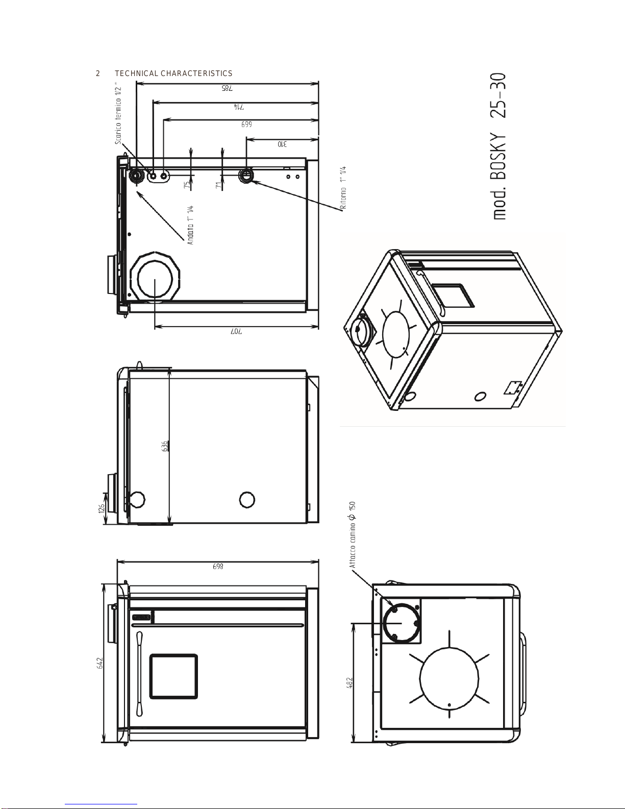
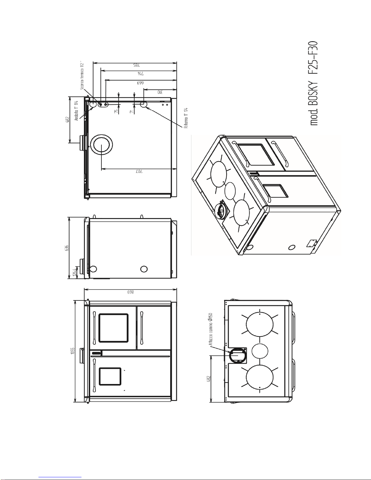
2 TECHNICAL CHARACTERISTICS
Page 22
Page 23
Page 24

Page 25

TECHNICAL DATA
BOSKY 25
BOSKY 30
BOSKY F25
BOSKY F30
Maximum output kW
29.6
30.5
29.6
30.5
Nominal output
kW
20,9
21.4
20.9
21.4
Nominal output Btu
72,000
73,000
72,000
73,000
Heat to water Kw
18
19.1
18
19.1
Heat to water Btu
61000
65000
61000
65000
Heat radiation from top kW
3 2 3
2
Width
mm
642
642
1055
1055
Depth
mm
636
636
636
636
Height mm
869
869
869
869
Firebox opening dim.mm
210x235
210x235
210x235
210x235
Firebox width
Max mm
300
300
300
300
Firebox depth
Max mm
442
442
442
442
Firebox height
Max mm
540
540
540
540
Oven width
mm
360
360
Oven depth
mm
550
550
Oven height
mm
320
320
Weight
221
221
304
304
Oven capacity
LT
63
63
Cook top dimen.
mm
525x525
525x525
930x525
930x525
Flue outlet D.
mm
150
150
150
150
Rear smoke outlet height mm
707
707
707
707
Heating connections D.
1" ¼ F
1" ¼ F
1" ¼ F
1" ¼ F
Boiler body content lt
27
27
27
27
Minimum flue draught.(Pa)
13
13
13
13
Smoke quantity (g/s)
20,8
20,8
20,8
20,8
Emissions CO (ppm at 02)
4692
4630
4692
4630
Flue temperature C
287
360
287
360
Efficiency %
71
70.1
71
70.1
Working pressure (bar)
1 1 1
1
Maximum working pressure (bar)
3 3 3
3
Electricity
220 V 50 Hz
220 V 50 Hz
220 V 50 Hz
220 V 50 Hz
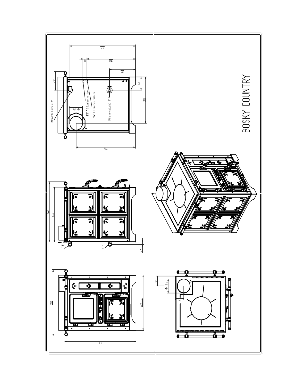
Page 26

Country
Country F
Maximum output KW
31.6
31.6
Maximum output Btu
108,000
108,000
Nominal output KW
21.4
21.4
Nominal output Btu
73,000
73,000
Heat to water KW
19.1
19.1
Heat to water Btu
65000
65000
Heat to air KW
2.3
2.3
Heat to air Btu
8000
8000
Height (mm)
850
850
Depth (mm)
600
600
Width (mm)
600
1048
Weight (Kg)
251
342
Diameter of flue (mm)
150
150
Firebox opening .mm
210 x 235
210 x 235
Firebox width mm
300
300
Firebox depth mm
442
442
Firebox height mm
540
540
Cooktop dimensions mm
480 x 480
930x480
Oven width
360
Oven depth
550
Oven height
320
Oven Capacity LT
63
Minimum flue draught (Pa)
13
13
Efficiency %
70
70
Water content (It)
27
27
Smoke quantity (g/s)
20,8
20,8
Emissions CO (ppm at 02)
4680
4680
Working pressure (bar)
1
1
Maximum working pressure (bar)
3
3
Electricity
220 V 50 Hz
220 V 50 Hz
Heating connections D.
1"F
1"F
Reloading time (min.)
75
75
ADVISORY; The values above (for the 25 & F25 and the 30 & F30) were obtained by using beech wood
in logs (9 logs) with a total weight of 7.2kg, their length was 400mm and the calorific value was
4104kcal/kg and the moisture was 12%. Using wood with different specifications to this will directly affect
performance, efficiency, ash formation, glass cleanliness and general dirtiness. The values above (for
the Country & Country F) were obtained by using beech wood in logs (9 logs) with a total weight of
7.6kg, their length was 400mmn and the calorific value was 4104kcal/kg and the moisture was 12%.
Using wood with different specifications to this will directly affect performance, efficiency, ash formation,
glass cleanliness and general dirtiness.
Page 27

2.1VITRIFICATION
The central heating cookers series 25 - 30 - F25 - F30 country, country F-can be
supplied with the boiler body with vitrification treatment. This treatment occurs at very
high temperatures that permit the glass and steel to melt into an alloy that is completely
impervious to corrosion attack caused by acid combustion smoke. Vitrification protects the boiler body
from corrosion caused by acid smoke and condensation developed by the combustion of the wood
fuel. The presence of surface defects such as indents, scratches, etc..., do not affect the life or
resistance of the corrosion proofing treatment. THIS GIVES THE BOILER BODY AN 8 YEAR
GUARANTEE
3GENERAL DESCRIPTION
3.1OPERATING PRINCIPLE
•Your central heating cooker has been constructed to satisfy all your heating and cooking needs.
3.2THE FUEL
CORRECT use of appliance when using wood fuel
For anyone interested in wood burning, there is much to learn; in the following text you
will find guidance and information on the subject.
Before installing or using a wood burning appliance, carefully read the manufacturers
installation procedure or if you are in any doubt as to the soundness of your chimney, call us and we
will be pleased to advise you. ALL WORK MUST COMPLY WITH CURRENT BUILDING
REGULATIONS.
The first few firings will if done correctly leave a light coating of ash on the flue pathways this will
minimise the risk of tar build up – therefore it is critical these firing are done as best practise and a hot
clean fire is established.
Remember that on the initial light up of the appliance, large amounts of water may run from the
appliance, this is quite normal and caused by massive condensation due to the fact that the boiler is
clock cold and the newly established fire is hot.
Maximum temperature difference = maximum condensation.
Once the water temperature in the boiler starts to increase the temperature difference starts to
decrease and so does the initial condensation.
Good woodburning technique
If wood is burned at high temperatures a more complete combustion occurs, complete combustion
means that most of the volatile hydrocarbons locked in the wood are released in the form of heat
generally displayed as long yellow flame combustion.
The higher the combustion chamber temperature, the more complete the combustion process.
Bad wood burning technique
Page 28

If wood is burned at low temperature then very little is achieved and incomplete combustion occurs.
Incomplete combustion is typified by wood tar deposits all over the internals of the firebox, flue ways
and door glass.
The lower the combustion chamber temperature, the worse the combustion and the greater the build
up of wood tar.
In really bad cases, wood tar can drip from the appliance.
GOOD wood burning technique increases the efficiency of the burn process.
BAD wood burning technique decreases the efficiency of the burn process.
GOOD wood burning technique decreases your running costs.
BAD wood burning technique increases your running costs.
GOOD wood burning technique increases the life expectancy of the boiler.
BAD wood burning technique decreases the life expectancy of the boiler.
GOOD wood burning technique results in a clean appliance and chimney.
BAD wood burning technique results in a tar covered appliance and chimney.
Below is an example of tar build up that caused excessive damage when the chimney
caught fire – totally preventable!
loading and running the appliance
The fire is ignited in the usual way and air is automatically admitted through the air inlet flap controlled
by the relevant setting of the thermostat knob.
When the fire is established, build it up slowly by adding a small quantity of wood, take care not to put
too much wood on at once otherwise this will;
Kill the fire.
Reduce the firebox temperature.
Create smoke.
Cause tarring.
Page 29

Cause condensation.
When the combustion chamber is up to a high enough temperature, the wood oil starts to vaporise
from the wood, and creates long yellow flames.
Secondary air is drawn in to mix with these flames and this further improves the combustion.
As the wood fuel burns away it slowly decomposes leaving a light grey coloured ash.
As is the case with all fires, if it is allowed to die down too much, it will not be possible to recover it.
Try to keep topping the firebox up regularly but do not overload it so as to kill the temperature of it.
If you need to keep the appliance in for longer periods of time such as overnight ‘banking’ try
topping it up with smokeless fuel otherwise let it go out and re light it. If it is filled up
completely and the air is shut down then it will stew and only leave damaging deposits of tar
both in the firebox and the flue.
ABOUT WOOD FUEL
Do I know how much wood I will need to burn?
Roughly 1 lb of wood equals 1Kw of energy; therefore if you need 30Kw of energy per hour you are
going to have to burn about 30 lbs of wood per hour.
Pine and Oak have different density therefore a tonne of Pine will take up substantially more volume
than a tonne of Oak.
If you work out how many Kilowatt hours are required to keep your property warm then you should be
able to work out the weight of wood required for a seasons heating.
Do I have a reliable and proven supplier of wood and do I know the cost?
Once you have established your seasons requirement you can order your supplies from a local wood
fuel supplier.
Do I know how to store the wood?
Before any wood is burnt, it should have a moisture content of no more that 20%.
This can be achieved by drying outdoors for 12 months and then under cover for the second 12
months assuming that the wood has been cut, split and stored in such a way as to allow adequate air
to circulate through the wood pile.
Ash is an exception to this rule as it can be cut early in the year and (providing it is stored correctly)
burned in the autumn.
Equipment to help me get the best from my wood burning appliance
There are many factors which will affect the running of your wood burning appliance but the most
common problems are:-
WET WOOD
RUNNING THE APPLIANCE AT THE WRONG TEMPERATURE
Page 30

INCORRECT INSTALATION
INCORRECT CHIMNEY
The main problem here is knowing
How do I know that the wood fuel is at the correct moisture content for burning?
How do I know if I am burning the wood at the correct temperature?
Two pieces of equipment will help here, a moisture meter will tell you what the moisture content of
your wood is and a flue thermometer will tell you what temperature your appliance is running at.
Both of these are available from us.
COAL
If you wish to burn ordinary house coal on a central heating stove or boiler you need to know how to
do it, and that the stove or boiler you use has the necessary design features.
Recommended solid fuels
Manufactured - sunbrite singles, sunbrite doubles, coalite, phurnacite and supacite. Natural anthracite large & small nuts, selected housecoal (trebles/large nuts and doubles/nuts), taybrite, coke.
Oversize fuel lumps should be broken down to size. Stones and other foreign bodies should be
removed when fuelling.
Fuel should be stored under cover and ventilated, particularly manufactured fuels which must be kept
dry. Wet kitchen refuse should not be burned.
Avoid excessive fire temperatures with solid fuel - they are unnecessary and may do serious harm to
the cooker. The first symptoms of an overheated cooker is the formation of clinker (melted ash) which
will damage the fire bricks.
Damaged firebricks should be replaced as soon as possible but may be temporarily repaired with fire
cement.
The main problems are nearly always caused by: Putting too much coal on a fire which is almost out and then opening the ash pan door to increase the
draw. If you put masses of coal on a low fire and then open the bottom ash access door or the water
temperature thermostat, the result will be that the fire will produce too much smoke which cannot burn
or which when it bursts into flames will cause a small explosion in the firebox and also up the
chimney, the latter being particularly dangerous.
Running the appliance at too low a temperature causing the fire to smoulder continuously.
Not riddling the fire often enough so preventing the required amount of combustion air reaching the
fire.
The name of the game is to keep your fire burning healthily. Build it up with small amounts regularly
rather than large amounts infrequently and use coal no smaller than doubles. Cobbles are better
because they allow plenty of air to get around the firebox.
When loading the fire with a fresh change of coal, if it is possible rake the hot or glowing embers to
the front of the firebox and put the new coal to the back. In this way the new coal will burst into
flames more quickly and the bright embers will encourage the smoke to ignite quickly.
Slack, shale, singles or small fuel will simply stop air getting through and cause the sooting and
exploding problems, which are to be avoided. Regular riddling is of prime importance, as mentioned
earlier.
If you get it wrong you will normally do it in the first week or month. In some cases the result can be a
blocked chimney in less than a week. The part of the chimney, which blocks up first, will be the pipe
connecting the cooker to the chimney. This pipe must be as near vertical as possible for coal burning.
Rear outlet flues or bends are to be avoided at all costs, according to building regulations the
minimum angle a flue pipe can run is 45 dg., although we think a minimum of 60 dg is better.
Page 31

Regular cleaning of the appliance and the chimney is essential the frequency of such cleaning would
be established by experience but we would think once every 6 weeks would be adequate.
A carbon monoxide alarm must be fitted in the same room as the cooker
Page 32

4INSTALLATION
It IS MANDATORY THAT ONLY A COMPETENT PERSONS SCHEME REGISTERED INSTALLER
IS USED IN ENGLAND, WALES AND SCOTLAND.
4.1 LOCATING THE CENTRAL HEATING COOKER
A vital aspect to consider is that the flooring of the room in which the central heating cooker is
installed must be capable of bearing the weight of the central heating cooker.
For Country, Country F - Ensure that there is always a minimum 200mm safety gap between the
central heating cooker and combustible materials at the sides and rear. Adhere to the recommended
minimum distances illustrated in the drawing below.
For the Bosky 25, 30, F25 & F30, side distances need only to be 75MM.
For inset installations ensure that the top cast iron cornice is insulated from the surrounding
furnishings by means of lateral air spaces or compressed vermiculite insullation board or similar noncombustable matieral.
On the country models the flow and return pipes are only available with rear connections because of
the ceramic panels as opposed to left hand or rear choice on the Bosky. Also the vintage models are
slightly wider (70mm) as the panels are convex (shown below)
Page 33

4.1.1 INSET CENTRAL HEATING COOKER
If you wish to integrate your central heating cooker with your kitchen furnishings or
with a particular furnishing arrangement remove the fold-away towel rack by undoing
the 2 screws as illustrated in the figure below and then mount the enamelled casing
(only for models 25 - 30 - F25 - F30 ) . It is also advisable to apply 75mm spacers to the sides of
the central heating cooker to prevent the heat from the top cast iron cornice from damaging the
adjacent furniture.
4.2 MOUNTING THE SAFETY HEAT EXCHANGER (OPTIONAL) 25 - 30 - F25.F30)
To install the safety heat exchanger remove the vertical door, the left side together with its insulation
and the vertical upright that holds the door together with its screws as indicated. Slide in the heat
exchanger (1) and secure it to the boiler using the hardware (2) provided. Close the hole with the plug
(3). By installing a thermal relief valve the excess heat is absorbed as soon as the central heating
cooker rises to excessive temperature values due to external causes. This function is called fast
disconnection phase.
Page 34

MOUNTING THE SAFETY HEAT EXCHANGER (OPTIONAL) Country, Country F
This must be carried out by removing the ceramic left handside panels ( acting as indicated in par .
4.13) .
Remove the cap ( 10 ) by turning the screws ( 7 ) and its washers ( 8 ) . Now attach the heat
exchanger ( 1 ) and accessories ( 2 ) ( 3 ) ( 4 ) ( 5 ) to the cooker . Now attach the two curves
provided ( 6 ) to exchanger then connecting the same to a safety relief valve linked to mains water . In
this way it absorbs the excess heat
By installing a thermal relief valve the excess heat is absorbed as soon as the central heating cooker
rises to excessive temperature values due to external causes. This function is called fast
disconnection phase
Page 35

4.3 WIRING DIAGRAM 25 - 30
The electrical connections must be made before mounting the left side panel as the terminal
block is located behind the left side panel (see the figure below on the right).
CAUTION: IT IS MANDATORY TO EARTH THE CENTRAL HEATING COOKER AS
ILLUSTRATED IN THE BELOW DIAGRAM. IF THIS INSTRUCTION IS NOT OBSERVED
SERIOUS DAMAGE, WHICH IS NOT COVERED BY WARRANTY, WILL RESULT TO THE
BODY OF THE CENTRAL HEATING COOKER. HAVE AN ELECTRICIAN CHECK THE
EARTHING. THERE MUST BE NO ELECTRIC POTENTIAL (VOLTS) BETWEEN THE EARTH OF
THE CENTRAL HEATING COOKER EARTH AND THE ACTUAL EARTH OF THE PLANT.
BELOW IS THE AUTOMATIC AIR CONTROL UNIT
Page 36

4.4 WIRING DIAGRAM F25 - F30
The electrical connections must be made before mounting the left side panel as the terminal
block is located behind the left side panel (see the figure below on the right).
CAUTION: IT IS MANDATORY TO EARTH THE CENTRAL HEATING COOKER AS
ILLUSTRATED IN THE BELOW DIAGRAM. IF THIS INSTRUCTION IS NOT OBSERVED
SERIOUS DAMAGE, WHICH IS NOT COVERED BY WARRANTY, WILL RESULT TO
THE BODY OF THE CENTRAL HEATING COOKER. HAVE AN ELECTRICIAN CHECK THE
EARTHING. THERE MUST BE NO ELECTRIC POTENTIAL (VOLTS) BETWEEN THE EARTH OF
THE CENTRAL HEATING COOKER EARTH AND THE ACTUAL EARTH OF THE PLANT.
Page 37

4.5 WIRING DIAGRAM COUNTRY - COUNTRY F
The electrical connections must be made before mounting the left side panel as the terminal
block is located behind the left side panel (see the figure below on the right.
CAUTION: IT IS MANDATORY TO EARTH THE CENTRAL HEATING COOKER AS
ILLUSTRATED IN THE BELOW DIAGRAM. IF THIS INSTRUCTION IS NOT OBSERVED
SERIOUS DAMAGE, WHICH IS NOT COVERED BY WARRANTY, WILL RESULT TO THE
BODY OF THE CENTRAL HEATING COOKER. HAVE AN ELECTRICIAN CHECK THE
EARTHING. THERE MUST BE NO ELECTRIC POTENTIAL (VOLTS) BETWEEN THE EARTH OF
THE CENTRAL HEATING COOKER EARTH AND THE ACTUAL EARTH OF THE PLANT.
BELOW LEFT IS A PHOTO OF THE WIRING BLOCK BELOW RIGHT IS THE AUTOMATIC AIR CONTROL UNIT
Page 38

PLUMBING INFORMATION
Primaries must be 28MM minimum. Flow and return pipework must be 22MM minimum.
The key feature of this layout is the injector tee, which allows primary gravity circulation to occur when
the pump is not running and induced gravity flow to occur when the pump is running.
To reduce the necessity of running four pipes from the boiler, it is possible to fit the injector tee at first
floor level and then to fit a flow and return only to the boiler connected diagonally as shown.
In case of electrical failure it is essential to allow at least 25% - 30% of the boiler output, to be
available as a form of gravity heat leak. This can be achieved by fitting radiators teed off the primary
circuit, as illustrated in the diagram
Page 39

Page 40

4.7 GUIDELINES FOR THE HYDRAULIC CONNECTIONS OF THE CENTRAL HEATING COOKER TO THE BOILER
COILS.
Thermal stores can be designed to integrate a variety of different heat sources and allow both hot
water and central heating to be carried out at maximum economy.
The size of the store is determined by the heat load of the property and hot water flow rates required.
In the illustration, the solar coil is used to provide heat into the thermal store, which can be used for
hot water production and as a contribution to central heating.
The wood stove, open vented oil or gas boiler, and immersion heater are all optional.
If unvented appliances are used a different version of the Thermal store can be used but this would
preclude the optional wood stove, if a wood stove option is required then the vented Thermal Store
must be used and it would require fitting on the floor above the wood stove as heat from the stove
must reach the store via natural gravity flow.
Depending upon the output of the wood stove boiler and the capacity of the store, it may also be
necessary to fit a heat leak radiator on the hot flow to the store.
Hot water for domestic use is provided via heat exchange from the large coil, with the correct size
heat sources, flow rates of up to 25 litres per minute can be achieved.
3
Note that the under floor option uses a sealed system as opposed to a vented system to stop cross
contamination from the other heat sources
Page 41

Page 42

4.8 GUIDELINES FOR THE HYDRAULIC CONNECTIONS OF THE CENTRAL HEATING
COOKER TO THE AIR-CASED BOILER.
Page 43

4.10 INSTALLATION OF CASING FOR BOSKY 25 - 30 - F25 - F30
After positioning the central heating cooker, connecting the electrical system and the hydraulic
system (only if using the rear delivery and return outlets) (see para. 4.2 - 4.3 - 4.4 - 4.5 - 4.6 - 4.7
- 4.8 - 4.9 ) proceed with the installation of the casing as illustrated in the images below:
Firstly mount the front profile (figure below right): -Lift and move away the cooktop (A) -Insert the
front profile (B) in the cast iron housing.
Fix the profile with the hardware specified below. -Next replace the cooktop (A).
Then mount the vertical door (figure below left) : -Mount the door on the hinges as indicated by the
arrows in the drawing on the left. Align the vertical door by adjusting the hinges.
- Fasten the front with 9 self-tapping screws TC+ 3.9X13 black z..
Page 44

Then mount the left side panel complete with insulation (see
figure on left):
-Fit the tabs (G) into the
rectangular holes under the left
side cornice -Fit the tabs (H)
into the holes in the base and
push the side panel back until it
locks in, then secure using the 2
screws indicated.
Mount the right side panel using
the same procedure.
4.13 MOUNTING SIDE PANELS COUNTRY COUNTRY F
After positioning the cooker proceed to mount the panels, as represented in the images below;
Proceed first to the fixing of ceramics ( 4 ) and ( 5 ) in their seats it is advisable to carry out
this operation by removing the doors themselves. Fix after degreased and dried both
ceramics and the seat, the same on the ceramic support with the thermal silicone supplied .
Before moving and reassembling the doors to the cooker you must wait at least 24 hours.
Remove profiles ( 2 ) and ( 1 ) .Now proceed to the assembly of the lateral ceramics ( 3 ) assembling
first the lower and then the upper . Insert the ceramic ( 3 ) as shown in Figure 2 and Figure 3 first
deforming the fins indicated
Page 45

Page 46

Provide for reassembling ceramics ( 6 ) by removing first the black knob of the flap adjustment fumes
and then pulling the central support ceramics ( 8 ) by pulling on the inside ; later proceed through the
use of screws ( 7 ) to fixing there ramiche ( 6 ) on the support ( 8 ) . Finally fix the support ( 8 ) full of
pottery to the cooker
2 Mounting side rails (OPTIONAL country, country F)
In order to assemble the side handles (optional) you must assemble before mounting ceramics.
Proceed fixing of the spacers ( 2 ) and the supports ( 4) through the screws (3 ) . Now attach the
group created at the cooker through the screws ( 1 ) . Now align the supports ( 4 ) and insert the rail (
7 ) . Insert the rail end plugs ( 6 ) and fix the grub screws
Page 47

5 OPERATION
5.1 DESCRIPTION OF MAIN CONTROLS AND COMPONENTS
5.1.1 DESCRIPTION OF MAIN CONTROLS AND COMPONENTS OF CENTRAL HEATING
COOKERS 25 - 30 - F25 - F30
The main controls and components listed below are located behind the enamelled door
on the boiler side and on the top surface.
A AUTOMATIC COMBUSTION AIR REGULATOR
B OVEN LIGHT SWITCH (ONLY F25-F30)
C WATER THERMOSTAT
D ANTI CONDENSATE THERMOSTAT
E WATER PUMP ACTIVATED LIGHT
F STARTER
G SMOKE DIVERTOR FLAP (ONLY F25-F30)
H TEMPERATURE SENSOR
I PRIMARY AIR
L ASH DOOR
M SECONDARY ASH DOOR
N GRATE POSITION LOCKING LEVER
O GRATE POSITION ADJUSTMENT LEVER
P SAFETY HEAT EXCHANGER (OPTIONAL)
Q LOADING DOOR
Page 48

5.1.2 DESCRIPTION OF MAIN CONTROLS AND COMPONENTS Country, Country F
A AUTOMATIC COMBUSTION AIR REGULATOR
C WATER TEMPERATURE GAUGE
D ANTI CONDENSATE THERMOSTAT(LOCATED BOTTOM LEFT BEHIND THE PANELS)
E WATER PUMP ACTIVATED LIGHT
F STARTER
G SMOKE DIVERTOR FLAP
H TEMPERATURE SENSOR
I PRIMARY AIR
L ASH DOOR
M SECONDARY ASH DOOR
N GRATE POSITION ADJUSTMENT NUT
P SAFETY HEAT EXCHANGER (OPTIONAL) (LOCATED LEFT BEHIND THE PANELS
Q LOADING DOOR
Page 49

5.2 LIGHTING AND STARTING THE CENTRAL HEATING COOKERS
Before using the central heating cooker make sure that all the movable parts are in
position; also remove any labels and stickers from the glass to avoid having
permanent traces remain on the surfaces. Verify that the hydraulic and electric
connections have been made perfectly.
REMOVE THE PROTECTIVE ADHESIVE FILM FROM THE COOKTOP.
To start the central heating cooker firstly activate the starter by lifting the pin until it hooks onto the
plate by means of the groove on it (see fig.above and on page F - 9 ; use the tool provided). Leave
the adjustment ring I - 14 open. Now make a small fire using paper or cardboard together with wood
chips or small pieces of wood, and keep adding bigger pieces of wood as the fire gets going. When
the combustion is well underway, turn the starter F - 9 to the home position and close the adjustment
ring I - 14.
CAUTION: DO NOT FORGET TO CLOSE THE ADJUSTMENT RING! IF IT IS LEFT
OPEN THERE IS A SERIOUS RISK OF THE BOILER OVERHEATING AND
SUBSEQUENTLY DAMAGING THE BOILER ITSELF. THIS DAMAGE IS NOT
COVERED BY WARRANTY AS IT WOULD BE THE RESULT OF NEGLIGENCE BY THE
USER. IF THE STARTER IS LEFT OPEN THE RESULT IS LESS HEAT TRANSFER TO THE
WATER IN THE CENTRAL HEATING COOKER AS THE ADDITIONAL HEAT EXCHANGER IS
NOT UTILISED.
5.3 OPERATION OF THE CENTRAL HEATING COOKERS
It must be noted the temperature gauge on the oven door reads 20c less than the interior
temperature of the oven and when the door has been opened it might drop, but this does not
reflect the interior temperature which regains its temperature quicker than the thermometer
Once the heater has been lit and started, the combustion can be increased or reduced by acting on
the automatic combustion air thermostat adjustment knob to adapt the central heating cooker to your
heating or cooking needs. The heating pump starts up as soon as the anti-condensation thermostat
calibrated at 60°C gives the start signal to the plant circulating pump.
The maximum thermal value is achieved by using fuel having a diameter of 5-7 cm , obviously bigger
pieces can be used but at the expense of less power. To rekindle the fire move the grate to
the lowest position. Move the handle (O) forward and backward several times: this will free
the grate slots of the combustion ash.
CAUTION : The wood load must always be suitable for the actual thermal absorption requirements of
the plant. Large firewood loads in limited absorption conditions result in the unburnt wood remaining
in the fIrebox for long periods of time. This situation encourages the distillation of the wood resulting
in the formation of large quantities of gases and vapours that are only partially burned. The gases
condense in the central heating cooker and in the tubes and create tarry deposits.
Page 50

5.4 GRATE POSITIONS IN THE 25, F25, 30 & F30
During the winter period the grate must remain in the lowest position in order to
guarantee the maximum heat exchange from the combustion to the boiler and
consequently to the water. There are 3 grate positions:
Lowered grate and only central heating
All the heat is transferred to the water to take full advantage of the wet surfaces.
Grate all the way up with flap (para. 5.5) on oven
All the heat is transferred to the cook top, the flame envelopes the oven completely.
Intermediate grate and flap positions
Combined by simply positioning the grate and flap in intermediate positions.
To lift the grate pull the grate handle down gently (O). When the grate is in the desired position
return the lever to its home position. The grate will be lifted to one of its 3 positions. If the
movement is hard, pull the handle back and forth several times in order to free the grate, before
taking it to the top position. It is easier to perform this operation when there is little material in the
firebox.
To lower the grate pull the handle (O) until the grate lifts slightly, lift the grate adjustment lever
release mechanism (N) and shift the handle (O) until the grate is lowered.
5.5 Grate position Country, Country F
Open the ash pan door (L) use the tool to rotate the nut (N) anti clockwise to raise and clockwise to
lower the grate.
The diagrams below shows the path of the heat showing the three grate positions and the how the
maximum amount of heat is transferred to the water in the boiler or the oven.
Page 51

5.5 HOW TO USE THE OVEN IN CENTRAL HEATING COOKERS F25 - F30
By acting on the smoke deviator flap (diagram below) the central heating cooker can have 2
operating modes:
-Only central heating, in this mode the oven cannot be heated, only the left side of the cook top
plate is heated. In this operating mode the maximum heat output is transferred to the water. –
Heating and cooking, in this mode the oven can be heated, the entire cook top plate is heated.
Only central heating Cooking and central heating
5.6 THE FOLD-AWAY TOWEL RACK (ONLY FOR
25 - 30 - F25 - F30)
Central heating cookers models 25 - 30 - F25 F30 are fitted with 2 practical foldaway racks for
hanging your washing on to dry.
To extend them simply pull out as indicated in
the figure on the right .
Page 52

6 CLEANING AND MAINTENANCE
6.1 GENERAL CLEANING
Before commencing any operation disconnect the central heating cooker from the electrical
power outlet. Your central heating cooker does not require any special maintenance; simply
adhere to the simple and basic, but regular controls and general cleaning. This will guarantee
regular operation and optimal output at all times. As for all machines that run on solid fuel, the
main enemy is undoubtedly the dirt generated by ash, condensation, poor fuels; consequently it
is important to clean the entire central heating cooker twice a year. The air inlets can be cleaned
with an ordinary vacuum cleaner.
However, we recommend having the flue outlet cleaned by a professional chimney
sweep.
Caution: The glass and all the glazed steel parts must be cleaned with water
and a gentle detergent when the oven has cooled.
6.2 ASH
The central heating cookers are fitted with 2 ash pans placed under the firebox base. To access the
pans you need to open the enamelled door of your central heating cooker completely. To collect the
ash simply shift the grate riddling handle (O) (see drawing below).
We recommend emptying the ash pans (G and P) on a regular basis to prevent them from filling up
completely. It is necessary to regularly clean under the oven by opening the plug K. and vacuuming
the ash deposits . To ensure that your central heating cooker performs efficiently it is advisable to
regularly clean the surfaces of the heat exchanger and of the smoke passages towards the chimney,
using the special equipment provided; to access them remove the cook top plates X as illustrated in
the drawing below. The tarry deposits reduce the exchange and consequently the output as well.
Page 53

6.3 CLEANING THE HOT PLATES
Clean the hot plates with a normal gentle detergent. After cleaning (for the models with non-vitrified
hot plate), protect the plate by applying a film of oil to keep it clean and shiny. As an alternative to
the oil apply a thin film of protective chrome paste (readily available from your local hardware store).
Take care when applying the paste not to indelibly dirty the cast iron side cornices. If you detect any
rust use a lightly abrasive scouring pad to remove it and then proceed to apply the protective oil or
chrome paste.
6.4 HOW TO REPLACE THE OVEN LAMP (ONLY F 25 - F 30 )
To replace the oven lamp firstly open the oven door. Use a screwdriver or round-tip blunt knife to
lever gently between the glass (V) and the oven back until the glass V comes off its fastening
hooks. Then remove the lamp L and replace it with a new one type E 14 25 W 230-240 V 300°C.
The lamp is not covered by warranty as it is a consumable object.
Page 54

6.5 RECOMMENDATIONS
-Every time you stoke the fire use the riddling tool to move the grate. Move the rod O indicated in
para. 6.2. The air passage through the firebox grate must always be unobstructed.
-Every 10 hours of operation at least or whenever necessary clean the ash pans G and P as
described in paragraph 6.2.
-Every 2 weeks or whenever necessary clean the internal surfaces of the heat exchanger, the oven
and the door K under the oven.
-Always ensure that the fuel fed into the firebox catches fire normally. Always ensure that this occurs
to prevent dangerous explosions in the firebox caused by the accumulation of unburnt gases. If these
explosions prove to be rather violent the manufacturer declines all responsibility for the mechanical
resistance of the glass and heater parts.
-Adhere strictly to the declared consumption: max. 8.5 Kg /hour for models 25 - F25
, max.10 Kg /hour for models 30 F30.
-Thoroughly clean the heater and flue at least twice each season
In the unlikely event that the appliance is not operating in freezing conditions the water must be
drained from the boiler to prevent frost damage
THERMOROSSI SPA DECLINES ALL RESPONSIBILITY FOR DAMAGES TO THINGS AND/OR
PERSONS CAUSED BY THE FAILURE TO OBSERVE THESE INSTRUCTIONS.
7 FLUE
CHIMNEYS basics
An efficient wood burning stove is one of the most effective ways to improve the energy efficiency &
reduce the CO2 emissions in a house. To achieve its optimal performance an efficient appliance
needs an efficient chimney system. The key to a well performing chimney is consistent insulation
along the entire length of the flue without cold spots.
Vacuum .05” WG average.
Solid fuel appliances need class 1 chimneys which are designed to deal with flue gas temperatures
above 260 deg C.
Class 1 chimneys can be of lined, masonary construction or of prefabricated insulated metal
construction.
The job of the chimney is two fold-:
1. To safely remove the products of combustion (SMOKE)
2. To generate suck (VACUUM) to provide the fire with an adequate supply of air.
3. DRAFT (suck or vacuum the chimney can develop) depends upon the following-:
THE HEIGHT.
THE POSITION OF THE TERMINAL RELATIVE TO OTHER, LOCAL, OBJECTS
THE DIAMETER.
THE TEMPERATURE OF THE GASSES IN IT. (lining and insulation may come into this)
THE RESISTANCE OF THE INNER SURFACE OF THE CHIMNEY.
THE AVAILABILITY OF ADEQUATE VENTILATION.
THE HEIGHT ABOVE SEA LEVEL
4. Any bend in any part of the chimney or roughness on the internal chimney wall will slow down the
velocity of rising gasses and reduce the effectiveness of the chimney.
5. Any slight reduction in the flue gas temperature will reduce the chimney vacuum or pull, hence
when the stove is slowed down for all night burning, as the flue gas cools down the chimney vacuum
reduces and as the chimney vacuum drops, the stove may well go out. This problem is highlighted
even more during very cold weather when the chimney can cool down even faster.
Minimum draft of 18/20 PASCAL 0.18/0.20 mBAR
BEWARE, no one can guarantee that a chimney will work even after relining has been carried out.
Check out your chimney, look around your locality at other chimneys to see if there is a localised
problem of down draughting.
Page 55

If you have bought a house and have no experience as to the performance of the chimney be very
careful, ask the previous owners and try to gather as much information as possible before you commit
yourself.
As a rough rule of thumb consider that if you have a 90 bend in the flue you will need an additional 1m
of height and for every metre of horizontal flue you will need an additional 2m of height.
LINING OF EXISTING CHIMNEY’S
Most old, leaking chimneys need lining and insulating with special materials designed to:-
1. Cure Leaks.
2. Reduce the build up of tar and soot on the walls of the flue.
3. Withstand the tremendous heat generated when tar and soot catch fire.
4. Generate a steady and controlled flue vacuum.
Old unlined chimneys are not suitable, if wood burning appliances are used on these chimneys the
following may happen:
Tar builds up on the brick faces of the internal chimney walls.
This build up can take from 12 months to 5 years, and as time passes the tar gets thicker and thicker,
in really bad cases the tar can work its way through the chimney walls into the plasterwork of
adjoining rooms staining the wallpaper or plaster and causing a pungent wood smoke smell which can
contaminate the affected rooms.
If a chimney in this state catches fire the results are severe causing bricks and mortar to crumble and
drop down the chimney, and tar to ouze through the affected walls.
Often, with a chimney fire of this nature it could well be necessary to remove the complete stack
taking out and replacing all the walls affected by the tar impingement.
Severe damage can also occur on some types of twin wall stainless steel chimneys, causing
distortion and leaks of flue gases.
A chimney cap is a device that is normally placed on top of a flue outlet for the purpose of facilitating
dispersion of the combustion products; it must satisfy the following requirements;
-have a useful exhaust section that is at least double the section of the flue outlet on which it is
inserted;
-have a shape that prevents the entry of snow or rain into the flue outlet;
-be built in such a way that venting of the combustion products is guaranteed regardless of wind
direction.
CHIMNEY HEIGHTS AND TERMINAL POSITIONS
Fig 1 is a rough guide about chimney heights and terminal positions.
Many manufacturers will call for a minimum flue height of 4.5 meters.
Document J of the building regulations provides details of the required statutory flue heights and
terminal positions, the British Standard for chimney height calculations is BS5854:1980. (1996)
It would be illegal to install any appliance in a residential dwelling without complying with
Document J or the manufacturers instructions.
In the schematic shown in fig1 chimney locations are graded on a scale of 1 to 4
4. being the optimum position.
3. being the next
2. being not very good and likely to cause problems
1. Being not capable of complying with current legislation.
Note that the fig 1 illustration is not accurate and should only be used as a general guide.
Before any instalation work is carried out, accurate compliance with Doc J of the Building Regs should
be ensured.
Page 56

Fig 1
Page 57

Page 58

FIG 2 Single Story Instalations INTERNAL
Page 59

FIG 3 TWO STORY INSTALATIONS INTERNAL
7.3 CONNECTION TO THE CHIMNEY
The smoke outlet can be connected at the top of the hotplate or at the back of the central heating cooker
using the hardware provided as illustrated in the figure below. If you wish to connect the chimney to the
back of the heater then you need to close the top smoke outlet with the cover provided, remove the
perforated cover from the back and remove the fixed cover by undoing the screws. Next connect the cast
iron flue collar using the hardware provided. There must be no narrowing of the pipes that connect the
central heating cooker to the flue outlet. The joints must be completely airtight. The number of elbows
used must be kept to a minimum. Horizontal runs must be kept to a minimum and have a minimum slope
of 4%. Never use the same flue outlet for more than one appliance.
Page 60

7.4 VENTILATION OF THE ROOMS
It is essential for the room in which the appliance is installed to be well-ventilated, also to guarantee
secondary air for combustion in the central heating cooker.
The natural air flow occurs directly through permanent apertures to the outside made in the walls of
the room, or by means of single or multiple ventilation ducting.
The ventilating air must come from outside and if possible, away from sources of pollution. Indirect
ventilation is also allowed by taking in air from rooms adjacent the one where the heater is installed
taking into account all the warnings and limitations specified below. •The apertures in the walls must
comply with the following requirements:
- -have an unobstructed section of at least 6cm² for each Kw of installed thermal power, with a
minimum limit of 100cm²;
- be made in such a way that the vent openings, both on the inside and outside of the wall, cannot be
obstructed;
- be protected with grills or similar systems in order not to reduce the section described above;- be
situated at floor-level.
-
The air flow can also be obtained from an adjacent room as long as:
- the adjacent room is equipped with direct ventilation in compliance with the points described above;
- in the room to be ventilated the installed appliances are only connected to one flue outlet;
- the adjacent room is not used as a bedroom or a common area of the building;
- the adjacent room is not a room with a fire hazard, such as storage sheds, garages, combustible
material store rooms, etc...;
- the adjacent room does not become a vacuum compared to the room to be ventilated due to an
opposite draught effect;
- the air flow from the adjacent room to the room to be ventilated is unobstructed through the
permanent apertures having an overall net secti]on of no less than that indicated above. These
apertures can be obtained by enlarging the space between the door and the floor.
Page 61

8 TROUBLESHOOTING
8.1 PROBLEMS CAUSES AND REMEDIES FOR BOSKY BOILERS
Difficulty lighting the fire
Burner is clogged
Clean the burner by shifting the grate
to the winter position and riddle until
the ash drops through
wood is too high or
pieces too large
Use smaller pieces of firewood and
more seasoned firewood
Insufficient air in the
room
Create an adequate opening for air
inlet(see PARA. 7.4)
Poor draft
See causes -remedies "Poor draft"
(below)
Firewood has not yet
caught alight
Open the fire rekindling ring (para.
5.1) and wait for it to catch alight
The water in the boiler has a tendancy to
boil
The ash pan door
and/or inspection fire
rekindling ring is open.
Close the ash pan door and/or the
flame rekindling ring
The pumps are not
working
Inspect the pumps
Tendancy to generate condensation
(presence of humidity/water in the ash pan
and under the heater)
thermostat
Replace thermostat
Poor draught
See causes -remedies "Poor draft"
(below)
Low boiler temperature
Connect pumps to panel
The boiler does not heat sufficiently
Firewood pieces are too
large
Boiler not large enough
for system
Split the firewood into smaller pieces
Smoke in the room.
Difficulty keeping the fire alight.
Difficulty reaching right oven temperature
Low temperature of cook top.
Flame insensitive to variations in draft.
Puffs of smoke while operating.
Soot deposits in hood.
Impossible to operate during the night (fuel
remains unburnt).
Water does not reach the required
temperature.
Poor draft
See causes -remedies "Poor draft"
(below)
Insufficient air in the
room
Create an adequate opening for air
inlet(see PARA. 7.4)
Oxidised cook top
Poor maintenance of the
cook top
para. 6.3
fuel burns too quickly).
Uncontrolled combustion.
Draft too strong
Reduce the draft by installing a
register in the chimney.
Difficulty in controlling the temperature.
Poor draft
Raise the flue outlet, install an
antidowndraft cap on the chimney
top.
Draft too strong
Reduce the draft by installing a
register in the chimney.
Page 62

Poor draft
Inspect the flue draft: Presence of
constrictions in the chimney, too
many curves, poor insulation;,section
too small / clean the flue outlet/ lift
the cook top and thoroughly clean
the smoke passage and in particular
the additional heat exchanger.
Puffs of smoke issue from the top of the
heater when the door is slammed shut.
Insufficient air in the
room
Create an adequate opening for air
inlet(see PARA. 7.4)
Variable draft
Raise the flue outlet, install an
antidowndraft cap on the chimney
top.
Variable combustion rhythm.
Good combustion only occasionally, almost
appears to depend on the wind conditions.
Insufficient air in the
room
Create an adequate opening for air
inlet
(see PARA. 7.4)
Legenda
Bianco
Canna fucile
Marron fumè
Beige
Rosso
Vetro est.
Vetro int.
Termometro
Key
White
Rifle barrel grey
Smoky brown
Beige
Red
External. glass
Internal. glass
Thermometer
Page 63

9 SPARE PARTS
9.1 SPARE PARTS FOR BOSKY 25 - 30 (PART 1).
Page 64

Page 65

Page 66

pg. 23
Page 67

pg. 67
Page 68

Page 69

pg. 69
Page 70

Page 71

pg. 71
Page 72

Page 73

pg. 73
Page 74

Page 75

pg. 75
Page 76

9.14 SPARE PARTS FOR BOSKY 25-30, COUNTRY (INSULATION COVERS ).
9.15 SPARE PARTS FOR BOSKY F25, F30 COUNTRY F (INSULATION COVERS).
 Loading...