

THERMOROSSI BellaVista R silent, BellaVista R plus Installation, Use And Maintenance Manual
Page 1
Page 2

Page
1
Installation, use and maintenance guide
BellaVista™ R Silent - BellaVista™ R Plus
Page 3

Page
2
Manuale d'installazione, uso e manutenzione guide
BellaVista™ R Silent - BellaVista™ R Plus
INDEX
1 - INTRODUCTION .................................................................................................................................. 9
1.1 GENERAL GUIDELINES .................................................................................................................................. 9
1.2 SAFETY GUIDELINES ..................................................................................................................................... 9
1.3 RECOMMENDATIONS ..................................................................................................................................... 9
1.4 GENERAL GUIDELINES .................................................................................................................................. 9
1.5 TRANSPORTATION AND STORAGE ............................................................................................................ 10
1.6 GUIDELINES FOR CORRECT DISPOSAL OF THE PRODUCT ................................................................... 10
2 – TECHNICAL CHARACTERISTICS.....................................................................................................11
3 – GENERAL DESCRIPTION .................................................................................................................12
3.1 OPERATING TECHNOLOGY ......................................................................................................................... 12
3.2 THE PELLET ................................................................................................................................................... 12
3.3 PELLET REFUELLING .................................................................................................................................. 12
4 - INSTALLATION ..................................................................................................................................13
4.1 APPLIANCE LOCATION ................................................................................................................................. 13
4.2 UNPACKING THE APPLIANCE ..................................................................................................................... 13
4.3 INSTALLATION OF GLASS ON BASE........................................................................................................... 14
4.4 RELOCATION OF THE CONTROL PANEL ................................................................................................... 15
4.5 INSTALLATION OF AIRBOX 3 VENTILATION KIT (OPTIONAL) .................................................................. 16
4.6 HANDLE .......................................................................................................................................................... 17
4.7 OPENING THE SLIDING DOOR OF THE COMBUSTION CHAMBER ......................................................... 18
4.8 DRAWING COMBUSTION AIR FROM OUTSIDE .......................................................................................... 18
5 – DESCRIPTION OF THE CONTROLS .................................................................................................19
5.1 DESCRIPTION OF THE CONTROL PANEL .................................................................................................. 19
5.2 DESCRIPTION OF THE POWER PANEL ...................................................................................................... 20
5.3 DATE/TIME: SETTING THE DATE AND TIME .............................................................................................. 21
5.4 CHRONO: ON/OFF PROGRAMMING ............................................................................................................ 21
5.5 LEVEL: OPERATING LEVEL SETTING ......................................................................................................... 23
5.6 THERMOCOMFORT: CONNECTION WITH THE HANDHELD CONTROL (OPTIONAL) ............................ 24
6 - OPERATION OF THE HANDHELD CONTROL THERMOCOMFORT (OPTIONAL) ...........25
6.1 INDICATORS OF THE HANDHELD CONTROL ............................................................................................ 25
6.2 USE OF THE HANDHELD CONTROL ........................................................................................................... 26
6.3 TRANSMISSION CODES SETTINGS ............................................................................................................ 27
6.4 CARE AND MAINTENANCE OF THE HANDHELD CONTROL..................................................................... 27
7 – USE OF THE APPLIANCE ............................................................................................................28
7.1 DESCRIPTION OF THE OPERATING STAGES ........................................................................................... 28
7.2 SWITCHING ON THE STOVE ........................................................................................................................ 28
7.3 COMBUSTION AND VENTILATION ADJUSTMENTS ................................................................................... 28
7.4 INFRARED REMOTE CONTROL ................................................................................................................... 28
7.5 CHANNELLING ............................................................................................................................................... 29
7.6 SWITCHING OFF THE APPLIANCE .............................................................................................................. 29
8 – ROOM TEMPERATURE THERMOSTAT / CHRONOTHERMOSTAT (optional) ................30
8.1 OPERATING WITH THE ADDITIONAL ROOM TEMPERATURE THERMOSTAT (not supplied) ................ 31
8.2 OPERATING WITH THE ADDITIONAL CHRONOTHERMOSTAT (not supplied) ......................................... 31
Page 4

Page
3
Installation, use and maintenance guide
BellaVista™ R Silent - BellaVista™ R Plus
9 - CLEANING AND MAINTENANCE ...................................................................................................... 32
9.1 FOREWORD ................................................................................................................................................... 32
9.2 CLEANING AND MAINTAINING THE APPLIANCE ....................................................................................... 32
9.3 AIR FILTER ..................................................................................................................................................... 34
9.4 CHARGING THE BATTERY OF THE THERMOCOMFORT HANDHELD CONTROL (optional) .................. 34
9.5 BATTERY REPLACEMENT FOR INFRARED REMOTE CONTROL ............................................................ 35
9.6 REPLACING THE BUFFER BATTERY OF THE CONTROL PANEL ............................................................ 35
10 – SMOKE DISCHARGE TUBE AND VENTILATION OF THE ROOMS .............................................. 36
10.1 FOREWORD ................................................................................................................................................. 36
10.2 ROOM VENTILATION .................................................................................................................................. 36
10.2.1 VENTILATION FROM ADJOINING ROOMS ......................................................................................................................... 36
10.3 SMOKE OUTLET .......................................................................................................................................... 36
10.3.1 CHIMNEY TYPES ................................................................................................................................................................. 36
10.3.2 FLUE OUTLET / FLUE SYSTEM COMPONENTS ................................................................................................................ 37
10.3.3 CONTROLS PRIOR TO INSTALLING THE APPLIANCE ...................................................................................................... 38
11 – ALARMS .......................................................................................................................................... 39
12 - ELECTRICAL WIRING ..................................................................................................................... 40
13 - INFORMATION FOR THE SKILLED TECHNICIAN .......................................................................... 41
13.1 MAIN COMPONENTS AND THEIR OPERATION .................................................................................... 41
13.2 PRESCRIPTIONS FOR CORRECT OPERATION ....................................................................................... 41
13.3 TROUBLESHOOTING CAUSES-SOLUTION .............................................................................................. 42
14 – SPARE PARTS ................................................................................................................................ 44
14.1 SPARE PARTS 1/6 ....................................................................................................................................... 44
14.2 SPARE PARTS 2/6 ....................................................................................................................................... 44
14.3 SPARE PARTS 3/6 ....................................................................................................................................... 45
14.4 SPARE PARTS 4/6 ....................................................................................................................................... 45
14.5 SPARE PARTS 5/6 ....................................................................................................................................... 46
14.6 SPARE PARTS 6/6 ....................................................................................................................................... 46
Page 5
Page
4
Manuale d'installazione, uso e manutenzione guide
BellaVista™ R Silent - BellaVista™ R Plus
EU Declaration of Conformity (DoC)
Dichiarazione di Conformità UE (DoC)
Company name:
Azienda:
THERMOROSSI S.P.A.
Postal address:
Indirizzo:
VIA GRUMOLO, N° 4
Postcode and city:
Codice postale e città:
36011 ARSIERO (VI)
Telephone number:
Numero di telefono:
0445/741310
E-mail address:
Indirizzo e-mail:
INFO@THERMOROSSI.IT
declare that the DoC is issued under our sole responsibility and belongs to the following product:
dichiara che la dichiarazione viene rilasciata sotto la propria responsabilità e si riferisce al seguente prodotto:
Apparatus model / Product:
Descrizione prodotto:
Stufa a pellet
Pellet stove
Trademark:
Marchio
THERMOROSSI S.P.A.
Model/Type:
Modello/Tipo:
BellaVista™ R Silent
BellaVista™ R Plus
Date/Batch / Serial number:
Data/Numero di serie / di lotto:
L'oggetto della dichiarazione di cui sopra è conforme alla pertinente normativa di armonizzazione dell'Unione:
The object of the declaration described above is in conformity with the relevant Union harmonisation legislation:
•
Direttiva 2014/30/UE, EMCD
•
Direttiva 2014/35/UE, LVD
•
Direttiva 2011/65/UE, RoHS
•
2014/30/EU Directive, EMCD
•
2014/35/EU Directive, LVD
•
2011/65/EU Directive, RoHS
Sono state applicate le seguenti norme armonizzate e/o specifiche tecniche:
The following harmonised standards and/or technical specifications hav been applied:
EN 55014-1
EN 55014-2
EN 61000-3-2
EN 61000-3-3
EN 60335-1
EN 60335-2-102
EN 62233
EN 50581
EN 14785 tests carried out by the notified laboratory Kiwa Cermet Italia S.p.a (N.B. 0476) Viale Venezia, 45 31020
San Vendemiano (TV).
Arsiero, 16/03/2017
Firma/Sign.
Page 6

Page
5
Installation, use and maintenance guide
BellaVista™ R Silent - BellaVista™ R Plus
Dichiarazione di Prestazione
Declaration of Performance
Dichiarazione di prestazione in accordo con il Regolamento (UE) 305/2011
Declaration of performance according to Regulation (EU) 305/2011
N° 70
1
Codice di identificazione unico del prodotto-tipo:
Unique identification code of the product type:
BELLAVISTA™ R SILENT, apparecchio per il riscaldamento domestico, senza acqua,
alimentato a pellet di legno
BELLAVISTA™ R SILENT, residential space heating appliance without water fired by wood
pellets
EN 14785:2006
2
Numero di tipo, lotto, serie o qualsiasi altro elemento che consenta l'identificazione del prodotto
da costruzione ai sensi dell'articolo 11, paragrafo 4:
Type, batch or serial number or any other element allowing identification of the construction
product as required under Article 11( 4):
BELLAVISTA™ R SILENT
3
Uso o usi previsti del prodotto da costruzione, conformemente alla relativa specifica tecnica
armonizzata, come previsto dal fabbricante:
Intended use or uses of the construction product, in accordance with the applicable harmonised
technical specification, as foreseen by the manufacturer:
Apparecchio per il riscaldamento domestico, senza acqua, alimentato a pellet di legno
Residential space heating appliance without water fired by wood pellets
4
Nome, denominazione commerciale registrata o marchio registrato e indirizzo del fabbricante ai
sensi dell'articolo 11, paragrafo 5:
Name, registered trade name or registered trade mark and contact address of the manufacturer
as required pursuant Article 11( 5):
THERMOROSSI S.P.A. Via Grumolo, n° 4 36011 Arsiero (Vicenza)
5
Sistema o sistemi di valutazione e verifica della costanza della prestazione del prodotto da
costruzione di cui all'allegato V:
System or systems of assessment and verification of constancy of performance of the
construction product as set out in Annex V:
Sistema 3 e 4 / System 3 and 4
6
Nel caso di una dichiarazione di prestazione relativa ad un prodotto da costruzione che rientra
nell'ambito di applicazione di una norma armonizzata:
In case of the declaration of performance concerning a construction product covered by a
harmonised standard:
L' organismo notificato KIWA CERMET ITALIA S.p.a. N° 0476 ha determinato il prodottotipo in base a prove di tipo secondo il sistema 3 ed ha rilasciato il rapporto di prova 2001795
The notified laboratory KIWA CERMET ITALIA S.p.a. N° 0476 performed the determination
of the product type on the basis of type testing under system 3 and issued test report 2001795
Page 7

Page
6
Manuale d'installazione, uso e manutenzione guide
BellaVista™ R Silent - BellaVista™ R Plus
7
Prestazione dichiarata / Declared performance
Specifica tecnica armonizzata:
Harmonized technical specification:
EN 14785:2006
Caratteristiche Essenziali
Essential characteristics
Prestazione / Performance
Sicurezza antincendio / Fire safety
Reazione al fuoco / Reaction to fire A1
Distanza da materiali combustibili
Distance to combustible materials
Minime distanze / Minimum distances (mm):
posteriore / rear = 200
lati / sides = 400
frontale / front = 1,000
soffitto / ceiling = pavimento / floor = -
Rischio di fuoriuscita di braci incandescenti
Risk of burning fuel falling out
Passa / Pass
Emissione di prodotti della combustione
Emission of combustion products
CO 65.0 mg/m3 Alla potenza termica nominale / Nominal heat
output
CO 429.0 mg/m3 Alla potenza termica ridotta / Reduced heat
output
Temperatura superficiale / Surface temperature
Passa / Pass
Sicurezza elettrica / Electrical safety
Passa / Pass
Pulizia / Cleanability
Passa / Pass
Maximum working pressure
Maximum operating pressure
-- bar
Temperatura fumi a potenza termica nominale
Flue gas temperature at nominal heat output
T 187 °C
Resistenza meccanica (per sopportare un
camino/una canna fumaria)
Mechanical resistance(to carry a chimney/flue)
NPD {Nessuna Prestazione Determinata}
Potenza termica nominale / Nominal heat output 8.98 kW
Potenza termica resa in ambiente / Room heating output 8.98 kW
Potenza termica ceduta all’acqua / Water heating output - - kW
Rendimento
Efficiency
85.36 % Alla potenza termica nominale / Nominal heat output
85.26 % Alla potenza termica ridotta / Reduced heat output
8
La prestazione del prodotto di cui ai punti 1 e 2 è conforme alla prestazione dichiarata di cui al
punto 7. Si rilascia la presente dichiarazione di prestazione sotto la responsabilità esclusiva del
fabbricante di cui al punto 4
The performance of the product identified in points 1 and 2 is in conformity with the declared
performance in point 7. This declaration of performance is issued under the sole responsibility
of the manufacturer identified in point 4
Firmato a nome e per conto del fabbricante da
(nome e funzione)
Signed for and on behalf of the manufacturer
(name and title)
Luogo/Place Data/Date
Arsiero 16/03/2017
Page 8

Page
7
Installation, use and maintenance guide
BellaVista™ R Silent - BellaVista™ R Plus
Dichiarazione di Prestazione
Declaration of Performance
Dichiarazione di prestazione in accordo con il Regolamento (UE) 305/2011
Declaration of performance according to Regulation (EU) 305/2011
N° 70A
1
Codice di identificazione unico del prodotto-tipo:
Unique identification code of the product type:
BELLAVISTA™ R PLUS, apparecchio per il riscaldamento domestico, senza acqua,
alimentato a pellet di legno
BELLAVISTA™ R PLUS, residential space heating appliance without water fired by wood
pellets
EN 14785:2006
2
Numero di tipo, lotto, serie o qualsiasi altro elemento che consenta l'identificazione del prodotto
da costruzione ai sensi dell'articolo 11, paragrafo 4:
Type, batch or serial number or any other element allowing identification of the construction
product as required under Article 11( 4):
BELLAVISTA™ R PLUS
3
Uso o usi previsti del prodotto da costruzione, conformemente alla relativa specifica tecnica
armonizzata, come previsto dal fabbricante:
Intended use or uses of the construction product, in accordance with the applicable harmonised
technical specification, as foreseen by the manufacturer:
Apparecchio per il riscaldamento domestico, senza acqua, alimentato a pellet di legno
Residential space heating appliance without water fired by wood pellets
4
Nome, denominazione commerciale registrata o marchio registrato e indirizzo del fabbricante ai
sensi dell'articolo 11, paragrafo 5:
Name, registered trade name or registered trade mark and contact address of the manufacturer
as required pursuant Article 11( 5):
THERMOROSSI S.P.A. Via Grumolo, n° 4 36011 Arsiero (Vicenza)
5
Sistema o sistemi di valutazione e verifica della costanza della prestazione del prodotto da
costruzione di cui all'allegato V:
System or systems of assessment and verification of constancy of performance of the
construction product as set out in Annex V:
Sistema 3 e 4 / System 3 and 4
6
Nel caso di una dichiarazione di prestazione relativa ad un prodotto da costruzione che rientra
nell'ambito di applicazione di una norma armonizzata:
In case of the declaration of performance concerning a construction product covered by a
harmonised standard:
L' organismo notificato KIWA CERMET ITALIA S.p.a. N° 0476 ha determinato il prodottotipo in base a prove di tipo secondo il sistema 3 ed ha rilasciato il rapporto di prova 2001795
The notified laboratory KIWA CERMET ITALIA S.p.a. N° 0476 performed the determination
of the product type on the basis of type testing under system 3 and issued test report 2001795
Page 9
Page
8
Manuale d'installazione, uso e manutenzione guide
BellaVista™ R Silent - BellaVista™ R Plus
7
Prestazione dichiarata / Declared performance
Specifica tecnica armonizzata:
Harmonized technical specification:
EN 14785:2006
Caratteristiche Essenziali
Essential characteristics
Prestazione / Performance
Sicurezza antincendio / Fire safety
Reazione al fuoco / Reaction to fire A1
Distanza da materiali combustibili
Distance to combustible materials
Minime distanze / Minimum distances (mm):
posteriore / rear = 200
lati / sides = 400
frontale / front = 1,000
soffitto / ceiling = pavimento / floor = -
Rischio di fuoriuscita di braci incandescenti
Risk of burning fuel falling out
Passa / Pass
Emissione di prodotti della combustione
Emission of combustion products
CO 47.0 mg/m3 Alla potenza termica nominale / Nominal heat
output
CO 206.0 mg/m3 Alla potenza termica ridotta / Reduced heat
output
Temperatura superficiale / Surface temperature
Passa / Pass
Sicurezza elettrica / Electrical safety
Passa / Pass
Pulizia / Cleanability
Passa / Pass
Maximum working pressure
Maximum operating pressure
-- bar
Temperatura fumi a potenza termica nominale
Flue gas temperature at nominal heat output
T 151 °C
Resistenza meccanica (per sopportare un
camino/una canna fumaria)
Mechanical resistance(to carry a chimney/flue)
NPD {Nessuna Prestazione Determinata}
Potenza termica nominale / Nominal heat output 10.68 kW
Potenza termica resa in ambiente / Room heating output 10.68 kW
Potenza termica ceduta all’acqua / Water heating output - - kW
Rendimento
Efficiency
86.43 % Alla potenza termica nominale / Nominal heat output
87.90 % Alla potenza termica ridotta / Reduced heat output
8
La prestazione del prodotto di cui ai punti 1 e 2 è conforme alla prestazione dichiarata di cui al
punto 7. Si rilascia la presente dichiarazione di prestazione sotto la responsabilità esclusiva del
fabbricante di cui al punto 4
The performance of the product identified in points 1 and 2 is in conformity with the declared
performance in point 7. This declaration of performance is issued under the sole responsibility
of the manufacturer identified in point 4
Firmato a nome e per conto del fabbricante da
(nome e funzione)
Signed for and on behalf of the manufacturer
(name and title)
Luogo/Place Data/Date
Arsiero 16/03/2017
Page 10

Page
9
Installation, use and maintenance guide
BellaVista™ R Silent - BellaVista™ R Plus
1 - INTRODUCTION
1.1 GENERAL GUIDELINES
This installation, use and maintenance guide is an integral and essential part of the product and must be kept by the user. Before
commencing with the installation, use and maintenance of the product, carefully read this guide. All local, national and European
regulations regarding the installation and use of the appliance must be met. The Manufacturer recommends carrying out all the
maintenance operations described in this manual.
This appliance must only be used as intended by the manufacturer. Any other use is considered incorrect and therefore hazardous;
consequently, the user shall be totally liable for the product if used improperly. Installation, maintenance and repairs must be carried
out by professionally qualified personnel, certified according to Decree no. 37 of 22 January 2008 and in compliance with current
regulations. In case of repairs only original spare parts supplied by the manufacturer must be used. Incorrect installation or poor
maintenance can injure or damage people, animals or things; in this case the manufacturer shall be relieved of all responsibility.
Before beginning any cleaning or maintenance operation switch off the appliance by means of the 0/I main switch and disconnect
the plug from the electrical power socket. The product must be installed in suitable locations and furnished with all the services
(power and outlets) which the appliance requires for a correct and safe operation. Any repairs or actions carried out on any
systems, components or internal parts of the appliance, or on any of the accessories supplied with it, that are not specifically
authorised by Thermorossi S.p.A, will automatically void the warranty and the manufacturer's responsibility, pursuant to Italian
Decree no. 224 of the President of the Republic of 24/05/1988, art. 6/b.
It is recommended to keep this manual in a safe place that is easily accessible to all users; if the manual is lost or deteriorated
contact the manufacturer for a replacement copy. If the appliance is sold or transferred to another user ensure that the manual is
handed over with it. The images and figures featured in this manual are purely illustrative and may differ from the actual product.
Furthermore, Thermorossi reserves the right to apply changes to the content of this manual anytime and without notice.
Thermorossi S.p.A. retains copyright on this manual. These instructions may not be reproduced or communicated to third parties or
used in any other way without the necessary authorisation.
1.2 SAFETY GUIDELINES
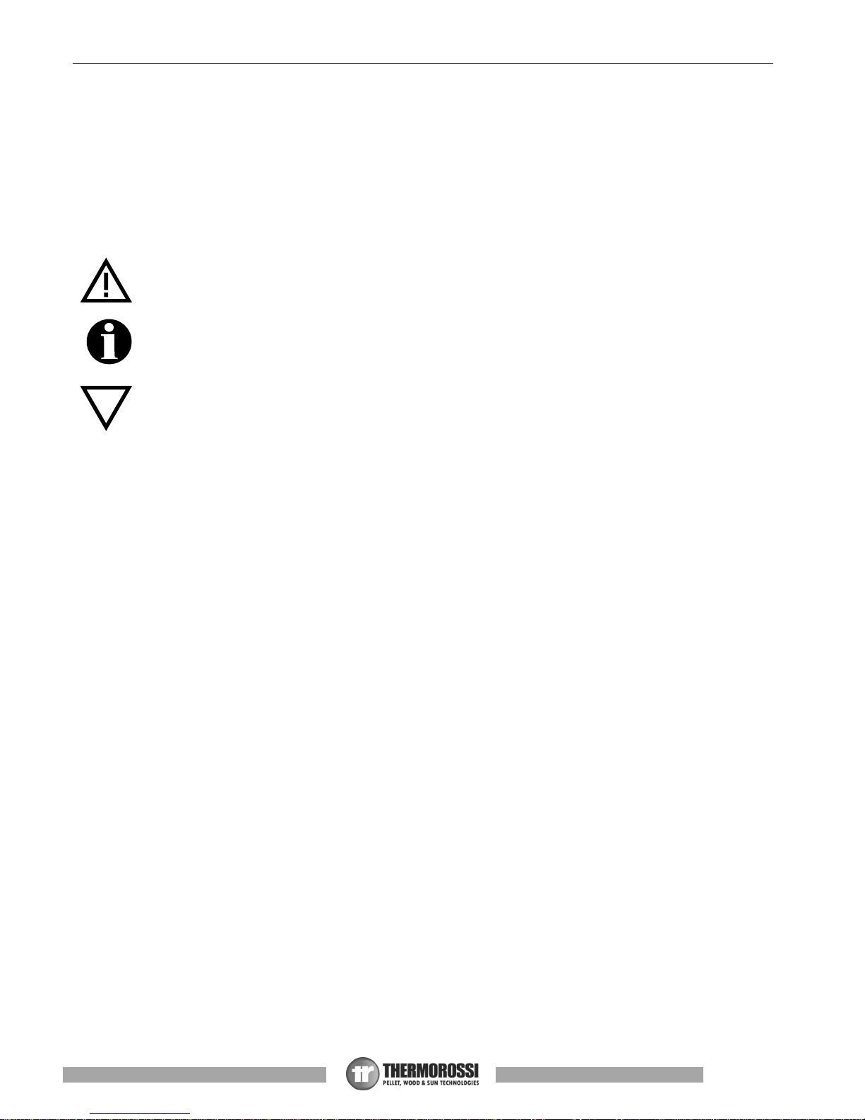
PERSONAL INJURY
This safet y symbol identifies important messages throughout the manual. Read the information
marked by this symbol carefully as non-observance of this message can cause serious injury to
persons using the appliance.
DAM AGE TO PROPERTY
This safety symbol identifies messages or instructions that are fundamental for the appliance and
system to function well. To avoid serious damage to the appliance adhere strictly to these
instructions.
INFORMATION
This symbol indicates important instructions for good functioning of the appliance. If this information
is not correctly observed, the performance of the appliance will not be satisfactory.
1.3 RECOMMENDATIONS
Before using the appliance, carefully read every section of this installation, use and maintenance guide as knowledge
of the information and the regulations contained in it are essential for a correct use of the appliance.
The entire operation concerning the connection of the electric panel must be carried out by expert personnel; no
responsibility will be accepted for damages, even to third parties, if the instructions for installation, use and
maintenance of the appliance are not followed scrupulously. Modifications made to the appliance by the user or on
his behalf, must be considered to be under his complete responsibility. The user is responsible for all the operations
required for the maintenance of the appliance before and during its use.
1.4 GENERAL GUIDELINES
Attention: the appliance must be connected to a system provided with a PE conductor (in compliance with the
specifications concerning low voltage equipment). Before installing the appliance check the efficiency of the earth
circuit of the power supply system.
Attention: the power supply line must have a section which is suitable for the power of the equipment. The cable section must in any
case be no less than 1.5 mm². The appliance requires powering with a voltage of 230V and 50 Hz. Voltage variations greater than
10% of the nominal value can cause irregular operation or damage the electrical device. Position the appliance so that the electric
power outlet in the room is easily accessible. Ensure that a suitable differential switch is installed upstream from the equipment.
Position the power supply cable in order to prevent any contact of the latter with the smoke exhaust pipe or hot parts of the
appliance. If the power cord is damaged it must be replaced by the manufacturer or by an authorised technical assistance service in
order to avoid risks.
Your appliance has obtained the CE marking and has been made to run for 1 hour to check that it functions correctly.
The product must not be used by children under the age of 8 years, by persons with physical, mental or sensorial impairments, or
by persons who are not familiar with the instructions for use and maintenance of the product (the instructions are found in this
booklet). Children must not play with the appliance.
Page 11
Page
10
Manuale d'installazione, uso e manutenzione guide
BellaVista™ R Silent - BellaVista™ R Plus
ATTENTION: before any use, make sure the burner is thoroughly clean and check that the sliding door of the combustion chamber
is properly closed and air-tight.
ATTENTION: during operation, the sliding door of the combustion chamber must always remain properly closed. It is strictly
forbidden to open it while the appliance is in operation. During operation, the smoke exhaust pipes, glasses, handles and some
parts of the appliance may reach extremely high temperatures: be careful not to touch them and also educate children to be aware
of said risks. Do not expose your body to hot air for long, do not overheat the room in which the appliance is installed, as these
actions could cause health problems. Do not expose plants or animals directly to the hot air flow as this could have noxious effects
on them. It is strictly prohibited to use any type of fuel (liquid, solid...) to light up the appliance: lighting must occur automatically as
intended and described in this installation, use and maintenance booklet; consequently, it is also strictly forbidden to feed pellets (or
any other material) into the brazier. Do not place non-heat resistant or inflammable or combustible objects in the vicinity of the
appliance: keep them at a suitable distance. Do not place wet clothing to dry on the appliance. When using a clothes horse, keep at
a suitable distance. It is strictly prohibited to disconnect the appliance from the electrical power mains while it is in operation.
Warning: do not wet the appliance and do not touch the electrical parts with wet hands. Never vacuum hot ash: this
could damage the vacuum device. All the cleaning operations described in this manual must be carried out when the
appliance is cold and shut off.
Attention! Warning for Swiss users
Refer to the local cantonal regulations imposed by the Fire Department (Mandatory signalling and safety distances )
and the Note concerning installation of heaters issued by the Association of Cantonal Fire Agencies (VKF - AEAI).
ATTENTION: it is mandatory to earth the appliance. If this instruction is not observed serious damage, which is not
covered by warranty, will result to the body of the appliance. Have an electrician check the earthing. There must be
no electric potential (Volt) between the earth of the generator and the actual earth of the systerm.
1.5 TRANSPORTATION AND STORAGE
TRANSPORTATION AND HANDLING
The appliance body must always be in a vertical position when handled and exclusively by means of trolleys. Take special care to
protect all the fragile parts from mechanical impact which could damage them and their correct functioning.
STORAGE
The appliance must be stored in a humid-free environment and sheltered from the weather; avoid placing the appliance directly on
the ground. The Company denies all responsibility for damage caused to wood floors or floors made from any other material.
It is inadvisable to store the product for long periods of time.
1.6 GUIDELINES FOR CORRECT DISPOSAL OF THE PRODUCT
At the end of the product’s useful life it must be disposed of in compliance with applicable regulations and in respect of the
environment, not with urban waste. The product must be consigned to designated sorted waste collection centres for the disposal of
electronic waste authorised by the local municipal councils. Correct disposal not only helps safeguard the environment but it also
promotes recovery and recycling of the materials.
Page 12

Page
11
Installation, use and maintenance guide
BellaVista™ R Silent - BellaVista™ R Plus
2 – TECHNICAL CHARACTERISTICS
M.U.
BELLAVISTA™ R
SILENT
BELLAVISTA™ R
PLUS
Height mm 1,493 1,493
Depth mm 670 – 971 670 – 971
Width mm 485 485
Empty weight Kg 180 180
Firebox power (Min. / Max.)* kW 3.89 / 10.52 4.43 / 12.36
Rated power Min. / Max.* kW 3.31 / 8.98 3.89 / 10.68
Consumption (Min. / Max.)* Kg/h 0.83 / 2.24 0.94 / 2.63
Ø smoke exhaust pipe mm 100 100
Min. draught at rated power Pa 12 12
Min. draught at reduced power Pa 12 12
Tank capacity Kg 25 25
Average smoke temperature at rated power* °C 187 151
Average smoke temperature at reduced power* °C 109 93
Smoke flow at rated power* g/s 8.0 11.3
Smoke flow at reduced power* g/s 6.1 7.0
Efficiency at rated power* % 85.36 86.43
Efficiency at reduced power* % 85.26 87.90
CO emissions with 13% O2 at rated power* mg/m
3
65 47
CO emissions with 13% O2 at reduced power* mg/m
3
429 206
Power supply voltage and frequency V / Hz 230V 50Hz 230V 50Hz
Max electrical consumption A / W 1.40 - 320 1.40 - 320
Min electrical consumption A / W 0.27 - 60 0.31 - 70
Heatable volume** m3 240 285
* All the data are based on the appliance fuelled with standards UNI EN 14961-2 A1 and A2 type-approved pellets.
** It is important to take into consideration the fact that the heatable volume is greatly influenced by the insulation of the
house (energy class of the building) and by the position of the appliance in the planimetry of the house, therefore the
indicated values may vary, even significantly.
485
1493
971
670
140
O
8
0
1493
485
670
O
1
0
0
440
1349
O
5
0
475
Page 13
Page
12
Manuale d'installazione, uso e manutenzione guide
BellaVista™ R Silent - BellaVista™ R Plus
3 – GENERAL DESCRIPTION
3.1 OPERATING TECHNOLOGY
Your appliance has been built to fully satisfy all your heating and practical requirements. Top-grade components and functions
managed with microprocessor technology guarantee high reliability and optimal performance.
3.2 THE PELLET
The appliance is fuelled by pellets, that is, cylinders of compressed sawdust; it his allows you to fully enjoy the heat of the flame
without having to manually stoke the combustion.
The pellets have a 6 mm diameter and a length between 10 e 20 mm. They have a max moisture content of 8%; a thermal value of
4000/4500 Kcal/kg and density of 630-640 kg/m³. It must be approved according to UNI EN 14961-2 A1 A2.
It is strictly forbidden to use any pellet type other than that specified above. The use of fuel that does not comply with the
above specifications not only immediately invalidates the warranty for the appliance but can also create dangerous
situations. Do not use the appliance as an incinerator, at the risk of voiding the warranty.
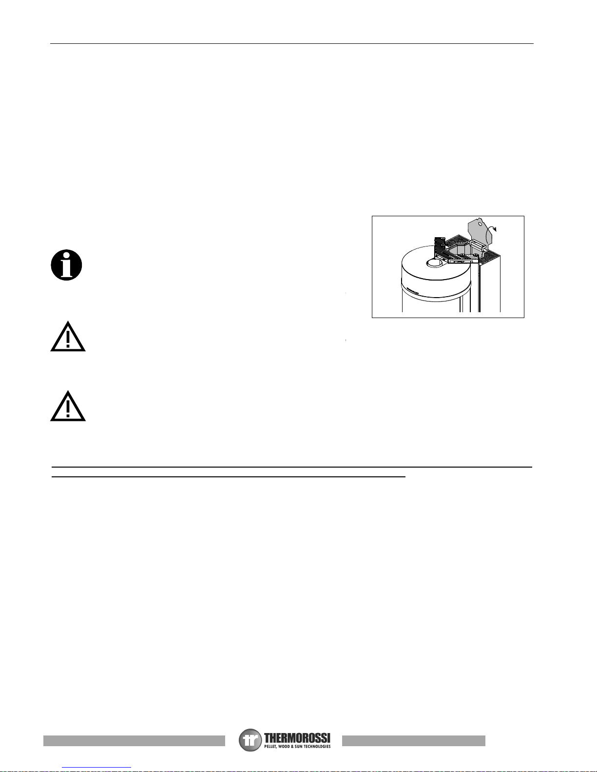
3.3 PELLET REFUELLING
The pellet feedbox is situated in the top part of the appliance. The load
capacity specified in the technical data can vary according to the specific
weight of the pellets.
Take special care when loading the tank as the screw feeder at its base is
in motion. Take care when topping up with fuel as the loading area can
get very hot.
ATTENTION: it is normal to find some pellets remaining in the tank even if
the stove shuts off because the pellets have run out.
Attention: when filling up the tank, take care not to drop any pellets into
the internal parts of the appliance, as, in extreme cases, this could generate live flames.
The manufacturer recommends emptying the tank and vacuuming the screw feeder zone once a month and during the
summer period. If the screw feeder can be seen when loading the pellet in the tank (pellet almost exhausted in the tank),
the appliance must be turned off, cooled down and the brazier must be cleaned. Do not switch off the appliance by
means of the main switch O/I on the power panel or by cutting off the power supply. Then restart the appliance.
Should you notice an excessive stagnation of flue gas in the combustion chamber, move away from the appliance
immediately. In particular move away from the glass sliding door of the combustion chamber. The excessive
concentration of unburned gases could create an explosion that could break the glass. Do not open the sliding door of
the combustion chamber for any reason and do not go near the appliance until said gases have been exhausted. Contact
a technical service centre to determine the causes. Do not switch off the appliance by means of the main switch O/I on
the power panel or by cutting off the power supply. Do not turn on the appliance for any reason whatsoever following an
event such as this.
Only pellets complying with the above specifications are to be loaded into the tank; in no case whatsoever must foreign
substances or objects be introduced into the tank, the brazier or any part of the generator.
Page 14
Page
13
Installation, use and maintenance guide
BellaVista™ R Silent - BellaVista™ R Plus
ATTENZIONE
Contiene vetro
E
A
B
C
C
D
D
E
4 - INSTALLATION
4.1 APPLIANCE LOCATION
Follow the general guidelines set out in paragraph 1.1 to the letter. Keep in mind that the flooring of the room in which
the appliance is to be installed must withstand the combined weight of the appliance and the pellets contained in the
tank.
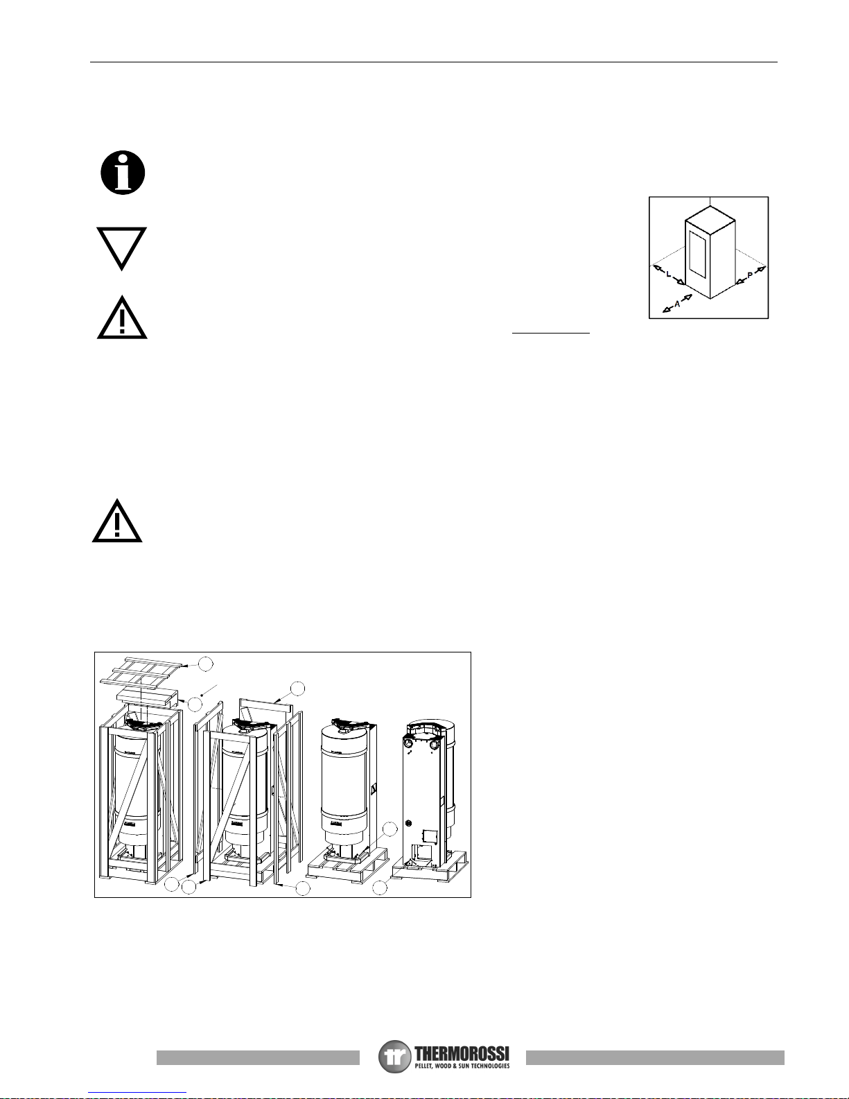
ATTENTION: The room where the appliance is installed must be well-ventilated and free
from humidity and salty air. A high level of humidity or saltiness in the room can lead to
the onset of rust or corrosion which will not be covered by warranty. The appliance must
be positioned at a minimum safe distance from walls and furnishings. If inflammable
materials are located in the vicinity of the appliance (e.g.: matchboarding, furniture,
curtains, pictures and paintings, sofas) it is mandatory to comply with the minimum
distances illustrated (see figure at right) Installation in the vicinity of heat-sensitive
materials is only permitted if suitable insulating and fireproof protection is placed
between the object and the appliance (ref. Uni 10683).
If the flooring is made of wood or any other combustible material, it is mandatory to install
a fireproof floor protector plate between the appliance and the floor. Failure to observe this
instruction will immediately invalidate the appliance warranty.
The installer must issue a certificate of conformity for the installation which includes the design plans and
the following documents:
a) Report containing the type of materials utilised.
b) Project as defined in Article 5 of Ministerial Decree n° 37 22 January 2008.
c) Drawing of the finished installation.
d) References to existing partial or previous declarations of conformity (e.g. electrical wiring).
e) Copy of the certificate of recognition of the professional technical qualifications.
These documents must, by law, be kept together with the use and maintenance booklet. The customer is responsible
for verifying, directly or indirectly, that the installation has been carried out to perfection in accordance with relevant
regulations in force. Do not install the appliance in unsuitable rooms such as bedrooms, bathrooms, garages and/or
lock-ups. It is forbidden to place the appliance in environments with an explosive atmosphere.
ATTENTION, the stove is not simply a household appliance: if the instructions set out in this booklet are not followed
and/or if installation of the appliance is not executed perfectly and/or the provisions in force are not strictly complied
with, dangerous conditions could arise for both objects and persons. It is the user’s responsibility to verify the presence,
in the room, of a vent necessary for supplying oxygen to the generator.
4.2 UNPACKING THE APPLIANCE
Proceed as follows to unpack the appliance:
1) Remove the top of the wooden crate (A).
2) Remove the box (B) very carefully and gently
since it contains extremely fragile material.
3) Remove the sides (C) of the wooden packaging.
4) Remove the sides (D) of the wooden packaging.
5) Remove the 4 screws (E).
6) Now remove the product from the pallet, making
sure not to damage it during handling.
A = 1,000 mm
L = 400 mm
P = 200 mm
Page 15
Page
14
Manuale d'installazione, uso e manutenzione guide
BellaVista™ R Silent - BellaVista™ R Plus
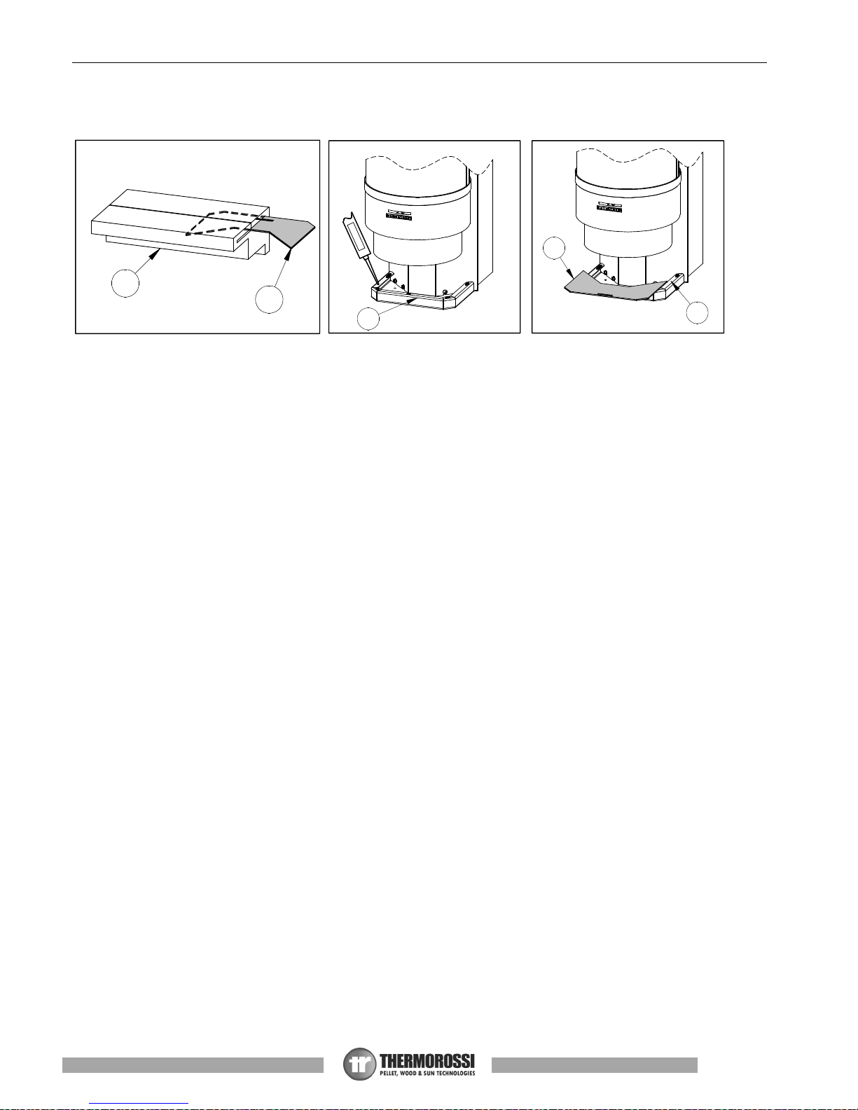
4.3 INSTALLATION OF GLASS ON BASE
1) Gently extract the glass (B) from the packaging (C)
2) Silicone-coat the surface of the base (A) using single-component, acetic silicone suitable for high temperatures (minimum
200°C, maximum 300°C).
3) Gently lay the glass (B) on the base (A), wait at least 24 hours before handling the product in order to let the silicone dry. If
the room temperature is lower than 18°, wait at least 48 hours until the silicone is completely dry.
B
C
S
I
L
I
C
O
N
E
A
A
B
Page 16

Page
15
Installation, use and maintenance guide
BellaVista™ R Silent - BellaVista™ R Plus
4.4 RELOCATION OF THE CONTROL PANEL
The product is supplied with the control panel on the right side; if needed, the control panel can be moved to the left side of the
appliance.
This operation must be exclusively performed by qualified professional staff, as set forth by Decree no. 37 of 22nd
January 2008 and applicable laws on the subject. Before performing said task, make sure the power supply cable is
disconnected from the electrical power socket.
Follow the procedures below to carry out this operation, referring to the images below:
1) Loosen the 2 Philips screws at the bottom (A) and the 3 Philips screws at the top (B).
2) Remove the rear panel (C), making sure not to scratch it.
3) Remove the metal sheet top (E) from the rear panel just removed (C), loosening the 3 Philips screws (D).
4) Mount the metal sheet top just removed (E) in the opposite side of the rear panel (C), so as to close the hole.
5) Loosen the 4 Philips screws (F) and remove the sheet protection of the control panel (G).
6) Loosen the two nuts (H) in order to remove the control panel (1) from the supporting bracket.
7) Secure the control panel (I) to the bracket (L), tightening the 2 nuts previously loosened.
8) Mount and secure the metal sheet protection (G) previously removed, fastening it with the 4 Philips screws (F).
9) At the end, mount the rear panel (C), securing it with the 3 screws (B) and two screws (A).
Pay particular attention during this operation, making sure the control panel's cable does not come into contact with
the hot or moving parts of the appliance. If said rule is not abided to, the cable may be damaged thus voiding the
warranty.
B
A
C
E
C
D
G
F
H
I
L
Page 17

Page
16
Manuale d'installazione, uso e manutenzione guide
BellaVista™ R Silent - BellaVista™ R Plus
A
I
H
G
C
H
I
G
D
E
C - sx
C - dx
4.5 INSTALLATION OF AIRBOX 3 VENTILATION KIT (OPTIONAL)
Airbox 3 ventilation kit can be installed on the appliance. By introducing this optional, the appliance will become Plus, therefore
ventilated and ductable. Once the kit is connected, all parameters required to transform the product from Silent to Plus will be preloaded automatically, with the possibility to change the fan's speed directly from the control display.
This operation must be exclusively performed by qualified professional staff, as set forth by Decree no. 37 of 22nd
January 2008 and applicable laws on the subject. Before performing said task, make sure the power supply cable is
disconnected from the electrical power socket.
Follow the procedures below to install Airbox 3 ventilation kit:
B
C
E
F
D
1) Unpack the ventilation kit
2) Remove the plug (A) from the appliance, pulling
downward
3) Introduce the condenser (B) in the specific hole,
fasten it with bolt (C) and couple connector (E) with
connector (F). At the end, push the fan inside until the
end-stop.
4) Remove the filter (G) and secure the fan at the top by
means of bolt (H) and washer (I).
Page 18

Page
17
Installation, use and maintenance guide
BellaVista™ R Silent - BellaVista™ R Plus
A
B
B
4.6 HANDLE
Your appliance is supplied with a handle (B) to open and close the sliding door of the combustion chamber and thus proceed with
maintenance operations. When not in use, the handle can be stowed on the back of the appliance if the hook provided is attached
to the stove. (A). (See figure).
A
B
C- dx
D
E
C - sx
5) Unscrew the 4 knobs (A) and remove the cast-iron top
(B), pulling it upward.
6) Insert deflectors (C – sx/LH) and (C – dx/RH). Open
the sliding door of the combustion chamber (for this
operation, refer to the specific chapter) and secure the
two deflectors with 4 screws (E) and 4 washers (D). Then
re-fit the cast
-
iron top (B).
Page 19

Page
18
Manuale d'installazione, uso e manutenzione guide
BellaVista™ R Silent - BellaVista™ R Plus
600
mm
4.7 OPENING THE SLIDING DOOR OF THE COMBUSTION CHAMBER
To open and close the sliding door of the combustion chamber, release the fastening hook (B) by acting on the suitable handle. In
the same way, release fastening hook (C) also by acting on the suitable handle. At the end of this operation, it is recommended to
remove the handle in order to avoid opening the door accidentally. Open the door only for cleaning operations and exclusively with
the appliance cooled off and disconnected from electric power.
4.8 DRAWING COMBUSTION AIR FROM OUTSIDE
The appliance is fitted with an intake to enable drawing in the combustion air directly from outside the building. Connect the air
intake on the appliance to the exterior of the building with suitable piping, capable of resisting high temperatures. The pipe’s length
must be maximum 600 mm.
ATTENTION: The suction duct must be protected with a grid and never be clogged. The protection grid, if installed,
must be inspected and cleaned on a monthly basis. Moreover, a suitable windbreak fitting must be installed in the
duct’s terminal.
A
D
A
B
C
D
Page 20

Page
19
Installation, use and maintenance guide
BellaVista™ R Silent - BellaVista™ R Plus
5 – DESCRIPTION OF THE CONTROLS
The appliance, when operating, could be hot to the touch, particularly the glass of the combustion chamber: take care
when handling the appliance components. Your appliance has obtained the CE marking and has been made to run for
at least one hour to check that it functions correctly. The product must not be used by children, by persons with physical
or mental impairments, by persons who are not familiar with the instructions for use and maintenance of the product
(the instructions are found in this use and maintenance booklet).
ATTENTION: before each use make sure that the burner is always very clean.
ATTENTION: during operation, the sliding door of the combustion chamber must always remain properly closed. It is
strictly forbidden to open the door while the appliance is in operation. While the appliance is in operation the smoke
exhaust pipes can reach extremely high temperatures: do not touch them! It is strictly prohibited to use any type of fuel
(liquid, solid...) other than pallet to light up the appliance: lighting must occur automatically as intended and described in
this installation, use and maintenance booklet; consequently, it is also strictly forbidden to feed pellets (or any other
material) into the brazier. Do not place non-heat resistant or inflammable or combustible objects in the vicinity of the
appliance: keep them at a suitable distance. Do not place wet clothing to dry on the appliance. When using a clothes
horse, keep at a suitable distance. It is strictly prohibited to disconnect the appliance from the electrical power mains
during normal operation.
5.1 DESCRIPTION OF THE CONTROL PANEL
The control panel is managed by a microprocessor. The control buttons and the various displays are described below.
The control buttons are:
Clock button
Press this button to activate / deactivate the programming.
Ventilation button (only in the PLUS version)
Press this button to set the desired level of ventilation: Six ventilation levels can be set on this stove. The fan starts
operating as soon as the temperature inside the stove body rises and the smoke thermocouple gives the signal.
The fan stops automatically when the stove body has cooled sufficiently. The fan cannot be disabled during
operation.
Flame button
Pressing this button when the appliance is off activates the START sequence, sets the power of combustion in the
WORK mode or shuts off the appliance by activating the OFF sequence.
Scroll buttons (only in the Menu)
Press MINUS key to lower the value. Press PLUS key to raise the preset value.
Menu button
Press this button to access the main menu. You can scroll the setting screens shown below, which will be
described in detail in the following paragraphs. To access the functions of each subwindow wait a few seconds.
Page 21

Page
20
Manuale d'installazione, uso e manutenzione guide
BellaVista™ R Silent - BellaVista™ R Plus
DATE/TIME This button is used to set the day of the week, the hour and minutes. (see para. 5.3)
CHRONO This button is used to set the programmed on and off sequences. (see para. 5.4)
LEVEL Is used to change the rotation speed of the smoke suction unit. (see para. 5.5)
THERMOCOMFORT This button is used to activate the connection with the optional handheld control. (see para. 5.6)
Display
The following information can appear on the display:
Displays the preset combustion power, and consequently the pellet consumption, by the number of bars that are
lit up around the flame symbol, using this logic:
One bar lit up: Minimum combustion power (and therefore with minimum pellet consumption)
Two bars lit: Second combustion power
Three bars lit: Third combustion power
Four bars lit: Fourth combustion power
Five bars lit up: Maximum combustion power (and therefore with maximum pellet consumption)
No bars lit up: The appliance is OFF
Only in the PLUS version it displays the preset ventilation power, and consequently the room fan speed, by
the number of bars that are lit up around the fan symbol, using this logic:
One bar lit: Minimum ventilation power
Two bars lit: Second ventilation power
Three bars lit: Third ventilation power
Four bars lit: Fourth ventilation power
Five bars lit: Fifth ventilation power
Six bars lit: Maximum ventilation power
Dashes appear along the top of the display, and each dash corresponds to one day of the week set by the user
(e.g. 1 corresponds to Monday, 2 corresponds to Tuesday… etc.).
The operating status of the appliance appears below these dashes, that is START, OFF or WORK. And the
current time set by the user appears below this word.
The presence in the display of the clock symbol indicates that the CHRONO programming has been enabled; if
this symbol does not appear it means that the CHRONO programming has been disabled. (see para. 5.4)
5.2 DESCRIPTION OF THE POWER PANEL
The components of the power panel present on the back of the
product are described below:
1) Electrical power outlet 220V-240V 50Hz
2) Main switch 0/I.
3) Test light for pellet feed motor.
The light comes on simultaneously with the activation of the pellet feed
motor.
4) Cap for reset thermostat button.
If the reset thermostat overheats stop the pellet feeder. The appliance
must cool down before you can restart the appliance. After verifying
and eliminating the causes of the event
undo the protective cap and press the button.
5) Protection fuse 3.15 A.
Legenda
Key
RIARMO RESET
SPIA MOTORIDUTTORE GEARMOTOR INDICATOR
3
4
2
1
5
SILENT version
PLUS version
Page 22

Page
21
Installation, use and maintenance guide
BellaVista™ R Silent - BellaVista™ R Plus
5.3 DATE/TIME: SETTING THE DATE AND TIME
The appliance must be energised and the I/0 switch in position “I".
The current date and time can be set using the DATE/TIME function.
To set the current time and date proceed as follows:
1) Press the Menu Button once to view the following screen:
2) After a few seconds the following screen will appear on the display:
3) Now press the Scroll Buttons to change the day of the week; each number corresponds to one day of the week (e.g. 1
corresponds to Monday, 2 corresponds to Tuesday, etc...). To confirm the selection of the day of the week press the Flame
Button.
Once confirmed, the selector shifts to the hour section while the selected day of the week remains framed:
4) Press the Scroll Buttons to change the hour. Once you have set the hour confirm the value by pressing the Flame Button.
Once confirmed, the selector shifts to the minutes section. Press the Scroll Buttons to set the minutes. Press the Flame
button to confirm.
Once confirmed, the date and time setting screen closes automatically and the initial screen returns to the display.
If you confirm the wrong value simply press the Menu Button several times to exit the box until the initial screen will appear, and
repeat the procedure described above.
5.4 CHRONO: ON/OFF PROGRAMMING
The appliance must be energised and the I/0 switch in position “I".
The CHRONO function allows you to set the weekly program by setting up to 3 on-off cycles at different times for every day from
Monday through to Sunday.
To set a program follow the procedure described below:
1) Press the Menu Button twice quickly to view the following screen:
After a few seconds the following screen will appear on the display:
2) Press the Scroll Buttons to select the day of the week on which you want to set the program. Each number corresponds to one
day of the week (e.g. 1 corresponds to Monday, 2 corresponds to Tuesday, etc...). To confirm the day of the week selected for
the programming press the Flame Button. The following screen will appear:
3) Now press the Scroll Buttons to select the hour at which you wish the appliance to start up automatically (ON1). Once the hour
has been set, confirm the value by pressing the Flame Button. When scrolling the ON1 values the OFF1 values will scroll as
well; this is to avoid setting a shut off time that is earlier than the start up time.
Once confirmed, the selector shifts to the minute section of ON1. Press the Scroll Buttons to set the minutes for the first start
up. Confirm the value by pressing the Flame Button.
4) Now press the Scroll Buttons to select the hour at which you wish the appliance to shut off automatically (OFF1). Once the
hour has been set, confirm the value by pressing the Flame Button.
Once confirmed, the selector shifts to the minute section of OFF1. Press the Scroll Buttons to set the minutes for the first shut
off. Confirm the value by pressing the Flame Button.
At this point the first ON/OFF cycle for the selected day has been set.
Page 23

Page
22
Manuale d'installazione, uso e manutenzione guide
BellaVista™ R Silent - BellaVista™ R Plus
The following screen will appear:
At this point if no further programming is required for that day go to point 5-A.
If, on the other hand, you wish to program a second ON/OFF cycle for that day go to point 5-B.
5-A) Press the Menu Button to exit the screen, in order to enable you to program the times for the ON/OFF cycles for the other
days of the week. In this case repeat the instructions from point 2 up to this paragraph.
5-B) Press the Scroll Buttons to select the hour at which you wish the appliance to start up automatically for the second time
(ON2). The start up time will be that set before OFF1; this is to avoid setting a second start up time that is earlier than the
preceeding shut off time. Once the hour has been set, confirm the value by pressing the Flame Button. When scrolling the
ON2 values the OFF2 values will scroll as well; this is to avoid setting a shut off time that is earlier than the start up time.
Once confirmed, the selector shifts to the minute section of ON2. Press the Scroll Buttons to set the minutes for the second
start up. Confirm the value by pressing the Flame Button.
Now press the Scroll Buttons to select the hour at which you wish the appliance to shut off automatically (OFF2). Once the
hour has been set, confirm the value by pressing the Flame Button.
Once confirmed, the selector shifts to the minute section of OFF2. Press the Scroll Buttons to set the minutes for the
second shut off. Confirm the value by pressing the Flame Button.
At this point the second ON/OFF cycle for the selected day has been set.
The following screen will appear:
At this point if no further programming is required for that day go to point 6-A.
If, on the other hand, you wish to program a third ON/OFF cycle for that day go to point 6-B.
6-A) Press the Menu Button to exit the screen, in order to enable you to program the times for the ON/OFF cycles for the other
days of the week. In this case repeat the instructions from point 2 up to this paragraph.
6-B) Press the Scroll Buttons to select the hour at which you wish the appliance to start up automatically for the third time (ON3).
The start up time will be that set before OFF2; this is to avoid setting a third start up time that is earlier than the preceeding
shut off time. Once you have set the hour confirm the value by pressing the Flame Button. When scrolling the ON3 values
the OFF3 values will scroll as well; this is to avoid setting a shut off time that is earlier than the start up time..
Once confirmed, the selector shifts to the minute section of ON3. Press the Scroll Buttons to set the minutes for the third
start up. Confirm the value by pressing the Flame Button.
Now press the Scroll Buttons to select the hour at which you wish the appliance to shut off automatically (OFF3). Once the
hour has been set, confirm the value by pressing the Flame Button. Once confirmed, the selector shifts to the minute
section of OFF3. Press the Scroll Buttons to set the minutes for the third shut off. Confirm the value by pressing the Flame
Button.
At this point the third and final ON/OFF cycle for the selected day has been set.
Alternatively, if you wish to copy the exact same programming for the ON/OFF cycles set for a particular day to the next day simply
press the Ventilation button.
For example: if I want to copy all the programmed ON/OFF cycles set for Monday to Tuesday the following screen will appear:
I press the Ventilation button once again to copy all the cycles programmed for Tuesday to Wednesday. The following screen will
appear:
Using the same logic we can copy the programmed cycles to the other days.
7) To conclude the programming operations simply press the Menu Button several times to exit the screen until the initial screen
will appear.
ATTENTION: The appliance ignores any ON or OFF command programmed with a value of 00:00.
Consequently if you do not wish to use an ON or OFF time setting simply set a value of 00:00. The appliance ignores
any ON or OFF command if the shut off time is set the same as or before the start up time.
Page 24

Page
23
Installation, use and maintenance guide
BellaVista™ R Silent - BellaVista™ R Plus
ATTENTION: In the event of a programmed cycle on always ensure that the brazier is clean. Failure to clean the
brazier can reduce and/or affect the life of the spark plug as it would be subjected to high temperatures due to poor
cooling. It is recommended to set ON/OFF cycles times lasting no less than 2 hours, in order to save energy and for
the proper operation of the appliance.
Enabling the programmed cycles:
Back in the initial screen, to enable the appliance to carry out the ON/OFF cycles as programmed it is necessary to press the Clock
Button.
The image of a clock will appear on the main screen:
The programmed cycles are now enabled.
When the programmed cycles are enabled (a clock symbol appears on the display) it will not be possible to
use an additional chronothermostat (see para. 8.2).
Disabling the programmed cycles:
To disable the appliance from carrying out the programmed ON/OFF cycles press the Clock Button once again.
On the display the clock symbol will disappear. This operation disables the weekly program that has been set by the user but does
not delete or reset the times.
Resetting the programmed cycles:
Moreover, it is possible to reset, in other words delete, all the programmed cycles entered by the user by holding down the Clock
Button in the initial screen for approx. five seconds.
The words CLEAR TIMERS will appear momentarily on the screen.
Do not release the button until the text CLEARED appears on the screen. Only the appearance of the words CLEARED
signal that the previously entered programmed cycles have been deleted. When the programmed cycles are active the
operating level at start up, that is the combustion power, will be the same level set before the last time the machine was
shut off: that is, only if it was a programmed shut off, not if the machine was shut off by means of a manual action.
Manual shut down can only be carried out with the programming disabled. If after a manual shut off the programmed
cycle re-enables, at the next programmed start up the appliance will be on the first combustion power level.
5.5 LEVEL: OPERATING LEVEL SETTING
The appliance must be energised and the I/0 switch in position “I".
Your appliance is delivered with an excellent program installed that favours combustion efficiency; the program is called LEVEL 1.
However, if you are using pellets with a higher than normal incidence of residues after combustion in the brazier, it is possible to
select alternative levels:
LEVEL 2 is an operating program that accelerates the speed of the smoke suction unit in proportion to all the combustion
power levels. This level must be set when the user notices a weak, high and very dark flame. Attention: this
modification does not authorise the use of below-standard pellets, or no vacuum in the flue outlet.
If using loosely compressed pellets, you could select:
LEVEL 0: is an operating program that decelerates the speed of the smoke suction unit when using loosely compressed
pellets and/or when the flue outlet has a very high vacuum, over 2 mm water column (20 Pascal).
The pellet consumption value remains unchanged regardless of the selected operating level. These variations will only change the
rotation of the smoke suction unit in the WORK stage, all the other stages will not undergo any changes.
Select the required Level by acting as follows:
1) Press the Menu Button three times quickly and the following box will appear:
Page 25

Page
24
Manuale d'installazione, uso e manutenzione guide
BellaVista™ R Silent - BellaVista™ R Plus
After a few seconds the following screen will appear on the display:
2) To change the operating level, hold down a Scroll Button while simultaneously pressing the other Scroll Button.
To set the desired level simply press the Menu Button several times until the initial screen will appear on the display.
The level selection can be made with the appliance OFF or ON. If the change is made while the appliance is running
the difference in the flame will be apparent. It is mandatory to pay particular care when selecting the most appropriate
operating cycle for your installation. After the selection of the operating cycle a thorough cleaning of the brazier is
mandatory.
5.6 THERMOCOMFORT: CONNECTION WITH THE HANDHELD CONTROL (OPTIONAL)
The appliance must be energised and the I/0 switch in position “I".
This function enables you to activate the connection of the appliance with the optional THERMOCOMFORT handheld control (See
Para. 6).
The THERMOCOMFORT function can be activated by proceeding as follows:
1) Press the Menu Button five times quickly until the following screen appears:
After a few seconds the following screen will appear on the display:
2) Press one of the two Scroll Buttons and the following screen will appear (Select ON to activate).
ATTENTION: It will only be possible to activate the THERMOCOMFORT function and select ON in the previous screen if the
appliance detects the handheld control signal. It is therefore recommended to ensure that the handheld control is energised and
within close vicinity of the appliance.
3) To confirm the activation of the THERMOCOMFORT function or to exit the screen simply press the Menu Button to return to the
initial screen.
The THERMOCOMFORT symbol will be present on the initial screen if the appliance is in the START or WORK stage:
The Thermocomfort function is automatically disabled when the appliance is OFF. It automatically reactivates at the next START
up.
To disable the THERMOCOMFORT function simply repeat operations 1 and 2, but this time select the OFF command. The
function will be disabled immediately.
Page 26

Page
25
Installation, use and maintenance guide
BellaVista™ R Silent - BellaVista™ R Plus
6 - OPERATION OF THE HANDHELD CONTROL THERMOCOMFORT (OPTIONAL)
The Thermocomfort handheld control is the instrument that allows you to optimise both consumption and functions.
If set in AUTO mode, the handheld control detects the room temperature where it is located and automatically manages the
modulation of the combustion power and the ventilation power (only in the PLUS version) of the appliance according to the target
temperature set by the user in the handheld control.
If set in MANUAL mode, the user can select both the ventilation power (only in the PLUS version) and the flame power.
6.1 INDICATORS OF THE HANDHELD CONTROL
1 Flame button
2 Ventilation button (only in the PLUS version)
3 DOWN key
4 UP key
5 Displays the room temperature detected by the handheld control sensor
6 Ventilation power indicator (only in the PLUS version)
7 Combustion power indicator
8 Target temperature indicator, use buttons 3 and 4 to change the value
9 Area of the display where the operating program is displayed
10 Battery charge level
11 Main switch 0-1 handheld control power supply
12 Battery charger connection
13 Code selector and batteries compartment cover
To switch on the handheld control, the following operations must be carried out:
1) Remove the battery cover and flick the main switch to ON, as illustrated in the figure below (This operation is only required
the first time you switch on the handheld control)
2) Flick the main switch upwards (11):
3) Connect the handheld control to the mains power supply by means of the supplied battery charger. The handheld control
must be recharged for at least 24 hours, as the rechargeable batteries could be partially or completely empty. Repeat the
same procedure every time the handheld control batteries discharge.
At the end of the winter season, in order to preserve the life of the batteries, it is mandatory to recharge the batteries and switch off
the handheld control completely by means of the switch located on the back (11). The batteries are guaranteed for 6 months. When
the batteries are exhausted dispose of them safely. It is normal for the temperature sensor to detect temperatures which are slightly
different to the real ones due to the thermostat tolerances.
Page 27

Page
26
Manuale d'installazione, uso e manutenzione guide
BellaVista™ R Silent - BellaVista™ R Plus
6.2 USE OF THE HANDHELD CONTROL
The Thermocomfort handheld control can be used with 4 different operating programs:
• MANUAL
• AUTO 5
• AUTO 3
• ECONOMY
To change an operating program hold down the DOWN arrow on the handheld control until the set program begins to flash. Now
release the DOWN arrow and quickly press the DOWN arrow (3) and/or UP arrow (4) to select the preferred operating program.
MANUAL
program
In the MANUAL program the room temperature thermostat of the handheld control is disabled. It will therefore be possible to
manually set both the ventilation power (only in the PLUS version) and the combustion power.
- To set or change the combustion power simply press the Flame Button (1), and the flame symbol on the screen will begin to
flash for several seconds. While it is flashing press the DOWN arrow (3) to reduce the combustion power, and on the display
you will see the bars disappear in sequence; vice versa to increase the combustion power, press the UP arrow (4).
The combustion level changes with each press of DOWN key (3) and UP key (4) .
- To set or modify the ventilation power (only in the PLUS version) simply press the Ventilation button (2), and the fan
symbol will begin to flash for a few seconds. While it is flashing press the Down arrow (3) to reduce the ventilation power, and
on the display you will see the bars disappear in sequence; vice versa to increase the ventilation power, press the Up arrow
(4).
The ventilation power changes with each press of DOWN key (3) and UP key (4).
Attention: it is possible that, due to radio interference or sending commands too close together, the changes will not
be implemented. With this program you can also use the infrared control supplied. It is normal that in the manual
cycle the room ventilation is often set at the maximum speed in order to cool the appliance body more effectively.
AUTO 5 program
In program AUTO 5 the room temperature thermostat is enabled. The handheld control adjusts the ventilation power (only in the
PLUS version) and power automatically in relation to the target room temperature set in handheld control display.
You can vary the desired room temperature by simply pressing DOWN key (3) and/or UP key (4).
The handheld control will set the maximum combustion and ventilation power (only in the PLUS version) and modulate them both
as the room temperature approaches the preset target temperature.
Once the target temperature has been achieved the combustion power and the ventilation power (only in the PLUS version) will
remain steady at the minimum value.
Attention: it is possible that, due to radio interference, the commands sent to the generator will not be implemented.
When using this program the infrared remote control supplied cannot be used.
Attention: the power and the ventilation depend on the preset target temperature, if the required temperature is too
high or not reachable the appliance could operate at maximum power for long periods of time.
AUTO 3 program
In program AUTO 3 the room temperature thermostat is enabled. The handheld control adjusts the ventilation power (only in the
PLUS version) and power automatically in relation to the target room temperature set in handheld control display.
You can vary the desired room temperature by simply pressing DOWN key (3) and/or UP key (4).
The handheld control will remain steady at the maximum value, level 3 for the combustion power and level 4 for the ventilation
power (only in the PLUS version), and lower the level as the room temperature approaches the preset target temperature.
Once the target temperature has been achieved the combustion power and the ventilation power (only in the PLUS version) will
remain steady at the minimum value.
Attention: it is possible that, due to radio interference, the commands sent to the appliance will not be implemented.
When using this program the infrared remote control supplied cannot be used. Caution: the power and the ventilation
depend on the preset value, if the required temperature is too high or not reachable the appliance could operate at
maximum power for long periods of time.
Page 28

Page
27
Installation, use and maintenance guide
BellaVista™ R Silent - BellaVista™ R Plus
ECONOMY program
In the ECONOMY program the appliance always operates at the minimum combustion power and the minimum ventilation power
(only in the PLUS version). When using this program the infrared remote control supplied cannot be used.
ATTENTION: THE THERMOCOMFORT HANDHELD CONTROL DOES NOT SWITCH THE APPLIANCE ON OR
OFF.
THE APPLIANCE MUST ALWAYS BE STARTED UP AND SHUT DOWN FROM THE CONTROL PANEL OR
THROUGH PROGRAMMING.
Keep in mind that radio wave transmissions can be affected by the surrounding environment: the presence of thick walls can reduce
the transmission that normally extends to 6-7 metres.
ATTENTION: to guarantee optimal data transmission it is advisable to always place the handheld control in its
support in a vertical position.
6.3 TRANSMISSION CODES SETTINGS
If there are several appliances installed in rooms closely to each other or in case of electromagnetic disturbances it may be
necessary to set different transmission codes as this type of interference deactivates operation of the optional Thermocomfort
handheld control.
To change the transmission codes proceed as follows:
The appliance must be energised and the main switch O/I in the "I" position.
1) Disable the Thermocomfort function (see para. 5.6)
2) Switch off the Thermocomfort handheld control using the main switch (11).
3) To change the transmission codes, open the battery cover and act as indicated in the figure below.
4) To change the frequency simply change the order of even only one of the four switches shown in the figure above.
5) Next switch on the handheld control by pressing the main switch (11).
6) Re-enable the THERMOCOMFORT function.
6.4 CARE AND MAINTENANCE OF THE HANDHELD CONTROL
The handheld control has been designed to the strictest standards and must be handled with great care.
If you observe the guidelines set out below, the handheld control will provide a long trouble-free performance:
• Protect the handheld control against precipitation, moisture, liquids and all those substances that could corrode the internal
electronic circuits. If the handheld control gets wet, remove it immediately from the battery charger if it is in the process of
charging, remove the battery and leave it open to dry at room temperature for as long as necessary.
• Do not use or store the handheld control in dusty or dirty environments. The dust/dirt could damage the movable parts of
the handheld control.
• Do not store the handheld control in very hot environments. High temperatures could shorten the life of the electronic
devices, damage the batteries and deform or even melt plastic parts. Do not store the handheld control in too cold
environments. When it heats up (when it returns to normal operating temperature), humidity could form inside it and
damage the electronic circuits.
• Do not drop the handheld control, do not hit or bump it and do not shake it. Actions such as these could damage the
internal circuits of the appliance.
• Do not use corrosive chemical substances, caustic solutions or detergents to clean the handheld control.
All the above guidelines apply to the handheld control, the battery, the battery charger, and all the accessories. The
parts subject to wear (such as batteries, keypads, lodging compartments, small compartment parts) are guaranteed
for 6 months from the purchase date. The guarantee does not apply if the defect is caused by non-conforming use
and/or if the instructions and guidelines described above are not observed to the letter. Devices or parts returned for
replacement become the property of Thermorossi. S.p.A. The presence of any irregular black-blue lines on the
display, also present when de-energised and/or battery flat or missing, indicate that the glass screen of the display is
damaged following a fall or impact: in this case the breakage is not covered by the guarantee.
CODE SELECTOR FOR HANDHELD RADIO CONTROL
CONTROLLED BY RADIO WAVES
Page 29

Page
28
Manuale d'installazione, uso e manutenzione guide
BellaVista™ R Silent - BellaVista™ R Plus
7 – USE OF THE APPLIANCE
7.1 DESCRIPTION OF THE OPERATING STAGES
START: has a duration of approx. 20 minutes, during this phase the appliance is programmed to light the flame. The appliance will
not accept power variations in the firebox. If the appliance does not start up correctly it could be due to one of the following factors:
cleanliness of the generator, smoke exhaust particularly cold, sudden surges and drops in the electric power supply, fuel is too
moist or does not comply with the specifications (see para. 3.2).
WORK: the appliance works according to the combustion and ventilation power (only in the PLUS version) set by the user. The
spark plug is dead.
OFF: has a duration of approx. 25 minutes. In this phase the appliance is switched off until a new "on" phase is initiated. The aim is
to make the pellet embers in the brazier die out and cool the appliance. The room fan (only in the PLUS version) and the smoke
suction unit continue to operate as required. In any case after approx. 25 minutes the appliance goes into stand-by mode.
7.2 SWITCHING ON THE STOVE
Before using the appliance check that all the movable parts are correctly fitted. Also remove any labels and stickers
from the glass to avoid that permanent traces remain on the surfaces. Verify that the electric connections have been
made perfectly. Also make sure that the sliding door of the combustion chamber is always closed properly and air tight.
Then carry out the following operations:
1) Power up the appliance and turn the I/0 switch to position “I”.
2) Ensure that the appliance is connected to the smoke exhaust: we recommend against using aluminium tubes and we
recommend always using sealing gaskets. Further information is given in paragraph dedicated to the smoke discharge of
this use and maintenance booklet.
3) Load the pellets into the hopper.
4) Press the Flame Button to begin the start up phase and the word START will appear on the display.
Press the Flame Button repeatedly to set the desired combustion power which will only activate at the end of the START cycle
which takes roughly 20 minutes.
In this stage any level of combustion power set by the user is ignored to meet the correct power values set by the manufacturer.
Press the Ventilation button (only in the PLUS version) repeatedly to set the six fan speeds; the fan will only activate once the
smoke has reached the preset temperature.
The electrical heater will start to overheat and only after a few minutes the first lot of pellets will start dropping into the brazier. This
occurs because the screw feeder has to fill up because it is completely empty. At the first start up the appliance may require the
starting sequence to be performed twice for the reason explained above: before starting up the second time empty and vacuum out
the brazier.
ATTENTION: During the START sequence the appliance ignores all the commands that are transmitted or set. Once
this phase has ended the word WORK appears on the display.
When the machine is in the running phase the combustion can be changed manually.
ATTENTION: If the appliance does not start up correctly check that the brazier and electric heater are clean. It is very
important to ensure that the tube lodging of the electric heater is clean; there must be no deposits or dust. It is
recommended to use an efficient ash vacuum cleaner but only when the appliance has cooled down.
7.3 COMBUSTION AND VENTILATION ADJUSTMENTS
Set the combustion power of the stove by acting on the Flamebuttonor on the supplied infrared remote control. The combustion
power regulates the pellet drop. The selected combustion power level will appear on the display.
Set the ventilation speed of the stove (only in the PLUS version)by acting on the Ventilation Button or use the supplied infrared
remote control. The ventilation speed regulates the number of fan revolutions. A slight vibration of the stove is quite normal when it
is running. The selected ventilation power level will appear on the display.
7.4 INFRARED REMOTE CONTROL
A practical infrared remote control is supplied with the appliance: act on the blue button to regulate the ventilation power (only in
the PLUS version), act on the grey button to start up, adjust the combustion power and shut off the appliance.
Page 30

Page
29
Installation, use and maintenance guide
BellaVista™ R Silent - BellaVista™ R Plus
7.5 CHANNELLING
It is possible to choose to distribute the flow partly to the front and partly to the channelling at the rear (only in the PLUS version).
Flow regulation takes place by acting on the suitable levers as indicated in the following figure:
ATTENTION: The temperature of the channelling levers is very hot while the stove is operating, so take care
not to touch them. They must only be activated using the special handle provided.
If there is no tube connected to the rear of the ducts, it is mandatory to check that there are no obstacles and
/or materials at the rear of the appliance that could be damaged by the heat due to possible incorrect
positioning of the channelling levers.
Prescriptions for correct channelling:
- - Use pipes with smooth inner surfaces capable of resisting continuous temperatures higher than 150°C.
- It is prohibited to use plastic or internally corrugated pipes.
- It is prohibited to position sections with a downward slope.
- Reduce the number of bends as much as possible (maximum 2).
- To ensure a good result it is mandatory to insulate the pipes with mineral wool resistant to at least 150°C.
- Maintain a distance of at least 20 cm between the channelling pipes and any inflammable materials.
- It is prohibited to reduce any pipe sections, even partially, with respect to the outlet diameter.
- It is prohibited to install devices that could completely close off the channelling.
7.6 SWITCHING OFF THE APPLIANCE
To switch off the appliance press several times the Flame Button until the power bars on the display disappear and the text OFF
appears.
DO NOT disconnect the generator from the electric power socket to switch it off. This operation generates smoke that
could not be evacuated because of the construction characteristics of the flue outlet.
The OFF procedure lasts for approx. 25 minutes.
Page 31

Page
30
Manuale d'installazione, uso e manutenzione guide
BellaVista™ R Silent - BellaVista™ R Plus
8 – ROOM TEMPERATURE THERMOSTAT / CHRONOTHERMOSTAT (optional)
The appliance can be connected to an additional room temperature thermostat or to an additional chronothermostat:
This operation must be exclusively performed by qualified professional staff, as set forth by Decree no. 37 of 22nd
January 2008 and applicable laws on the subject. Before performing said task, make sure the power supply cable is
disconnected from the electrical power socket.
For the additional room Thermostat connect terminals 7-8 of the terminal block CN7 to the board as indicated in the following
figures.
For the additional chronothermostat – modem connect terminals 9-10 of the terminal block CN7 to the board as indicated in the
following figures.
The contacts are defined as "FREE" contacts and they must never be supplied with voltage. It is strictly prohibited to
supply any tension whatsoever to the above-mentioned terminals as this would permanently damage the control board;
such damage is not covered by WARRANTY.
Follow the indications below to access the electronic board:
- Remove the rear as indicated in previous paragraphs
- Remove screws A and the board top B.
- Now you can access the board C.
Legenda
Key
Cronotermostato Modem Chronothermostat - Modem
Termostato Ambiente Room Temperature Thermostat
Contatti 9-10 della morsettiera CN7 Contacts 9-10 of the terminal block
CN7
Contatti 7-8 della morsettiera CN7 Contacts 7-8 of the terminal block CN7
A
A
B
C
Page 32

Page
31
Installation, use and maintenance guide
BellaVista™ R Silent - BellaVista™ R Plus
8.1 OPERATING WITH THE ADDITIONAL ROOM TEMPERATURE THERMOSTAT (not supplied)
An additional room temperature thermostat can be installed by connecting it to the board . The operating principle is as follows:
When the room temperature reaches the set temperature (only during the WORK phase) the thermostat closes the contact and the
appliance shifts to the minimum room ventilation speed (only in the PLUS version) and minimum combustion power. This
condition is shown on the display with the flashing of the bar indicating ventilation (only in the PLUS version) and the bar
indicating combustion: the appliance overrides all prompted commands. By using the room temperature thermostat the appliance
does not shut down, therefore electrical energy consumption is kept to the minimum and the heater has a longer life. When the
room temperature drops the thermostat opens the contact and the appliance returns to its original position in terms of thermal
power and ventilation (only in the PLUS version). The room temperature thermostat can be used to automatically start the
appliance with programming from the CHRONO.
ATTENTION: Use N.O. (normally open) contacts for the connection to the additional room temperature thermostat. The
thermostat must have a thermal hysteresis that is higher than 2°C.
8.2 OPERATING WITH THE ADDITIONAL CHRONOTHERMOSTAT (not supplied)
As an alternative to the room temperature thermostat, a chonothermostat can be installed by connecting it to the board. Using this
output when the chronothermostat contact closes the START cycle begins, whereas when the contact opens the OFF cycle begins.
The operating level at start up is the same as the level used before the last time the appliance shut down.
ATTENTION: when using the chronothermostat program up to a maximum of 3 on-off daily cycles without setting the
desired temperature or set it at the highest possible value for the chronothermostat.
At the end of the preset time the contact of the chronothermostat will open and perform the appliance shut down process. Similarly
at the preset startup time the contact will close and initiate the START cycle. The chronothermostat can be used to program start up
and shut down times and dates for the appliance. It is therefore possible to program a momentary shut down of the appliance
according to the preset time.
Do not shut down the appliance according to the room temperature.
If the external chronothermostat is used the “CHRONO" function cannot be used.
ATTENTION: The manufacturer denies all responsibility for the life of the electrical heater if subjected to excessive start
ups. It is recommended not to set the desired room temperature or to set it at the highest possible value for the
chronothermostat in order to avert this danger.
ATTENTION: Use N.O. (normally open) contacts for the connection to the chronothermostat.
ATTENTION: In the event of connections to the chronothermostat Thermorossi S.p.a. shall not be held responsible for the
appliance not starting up, smoke leaks or breakage of the lighting component. In the event of a programmed cycle on always
ensure that the brazier is clean and seated correctly in its lodging. A maximum of 3 on-off cycles per day are permitted. The
chronothermostat must have a thermal hysteresis that is not less than 2°C.
Page 33

Page
32
Manuale d'installazione, uso e manutenzione guide
BellaVista™ R Silent - BellaVista™ R Plus
9 - CLEANING AND MAINTENANCE
9.1 FOREWORD
Before beginning any maintenance operation ensure that the appliance is switched OFF and disconnected from the
electric power socket. Your appliance, being a pellet-fuelled appliance, requires regular general controls and
cleaning. This will guarantee regular operation and optimal output at all times. If the product is unused for a
prolonged period of time before starting up it is mandatory to inspect the smoke channel and outlet to ensure that
there are no obstructions. It is important to carefully follow the instructions set out below: failure to observe these
instructions could cause serious damage to the product, to the system, to objects and to persons using the appliance.
Attention: do not wet the appliance and do not touch the electrical parts with wet hands. Never
vacuum hot ash: this could damage the vacuum device. All the cleaning operations described in
this manual must be carried out when the appliance is cold.
The user must periodically clean the appliance, or have an authorised service centre clean it, as described in this manual.
Moreover, once a year it is advisable to have an inspection carried out of the functionality of the flue outlet.
9.2 CLEANING AND MAINTAINING THE APPLIANCE
Due to the frequent cases we have encountered of the use of poor quality pellets, users are advised that it is
mandatory to use, in this appliance, pellets certified in accordance with the regulations in force for the Italy UNI
market or for the European EN market. If this requirement is not observed the result will be unsuitable combustion,
consequently, the electrical and electronic components could be subjected to very high temperatures and will not be
covered by warranty.
Unless otherwise instructed, the operations described below are mandatory and not postponable beyond the
specified times.
EVERY DAY:
• Thoroughly clean the burner (Figure 1) with a vacuum cleaner; carefully clean the area around the spark plug. This is to ensure
that the appliance operates correctly and to avoid start up failures.
• Act on the 4 tube scraper levers by exercising some force, at least 4/5 consecutive times (Fig. 2 and 3).
EVERY WEEK:
•Check that the area where the Pelletpower® scraper works is sediment-free (Figure 4)
• Check that the holes of the burner and the heater lodging channel is completely sediment-free. If necessary vacuum and clean
(Figure 1)
• Remove, if present, all silica agglomerates; they indicate poor quality fuel.
• Unscrew the four knobs by turning them anti-clockwise and carefully vacuum the ash from compartment C1, C2 and C3 (Fig. 5
and 6). When re-fitting the cover, make sure there are no obstacles that prevent proper closure and check the gasket integrity. If
necessary replace the gasket.
• Unscrew the two knobs by turning them anti-clockwise and carefully vacuum the inspection compartments C4 (Fig. 7 and 8); once
closed, make sure there are no obstacles that prevent proper closure and check the gasket integrity. If necessary replace the
gasket.
• Clean the room air filter located at the bottom of the appliance (only in the PLUS version).
EVERY MONTH:
• Check that the smoke exhaust pipe is free from any ash deposits, above all in the initial parts.
• Vacuum the ash deposited on the bottom of the pellet tank.
AT LEAST TWICE A YEAR:
• Clean the flue outlet. If there are any horizontal sections, inspect them and clean out any ash and soot deposits before they block
the passage of the flue gases.
AT THE END OF THE WINTER SEASON (or whenever necessary)
• Perform a thorough overall cleaning of the firebox and compartments with brushes and vacuum cleaners.
A vacuum device simplifies the ash cleaning procedure. The frames and glass must be cleaned with a soft cloth and
only when the appliance has cooled down. The door of the combustion chamber must only be opened when the
appliance has completely cooled down: when it is opened it is normal for some ash to spill onto the floor.
Page 34

Page
33
Installation, use and maintenance guide
BellaVista™ R Silent - BellaVista™ R Plus
ATTENTION: after cleaning it is mandatory to carefully check that the sliding door of the combustion chamber is
firmly closed and airtight.
ATTENTION: the generator, the smoke channel and flue outlet must be cleaned in accordance with the specifications
described above and use of inflammable products is strictly forbidden: using inflammable products can create
dangerous situations. Lack of or poor maintenance prevents the appliance from operating correctly. Any problems
resulting from total or partial lack of cleaning or maintenance will immediately void the warranty.
ATTENTION: if the appliance remains inactive (and/or not used for over a month) the generator, the smoke discharge
tube and the flue outlet must be thoroughly cleaned and checked for any possible obstructions (e.g. birds nests in the
chimney cap) before restarting.
FIGURE - 2
FIGURE - 3
FIGURE
- 1
FIGURE
- 4
Pellet Power ®
Page 35

Page
34
Manuale d'installazione, uso e manutenzione guide
BellaVista™ R Silent - BellaVista™ R Plus
9.3 AIR FILTER
Your appliance is fitted with an air filter (only in the PLUS version); a practical device that prevents the circulation of dust particles
that are always present in domestic environments. The filter (shown in the image below) is installed on the back of the appliance.
Frequent cleaning will ensure greater availability of hot air during operation and less overheating of the appliance.
The filter must be removed and cleaned every week, with the appliance off and disconnected from power, soaking it in cold water;
dry it thoroughly before reinstalling it.
9.4 CHARGING THE BATTERY OF THE THERMOCOMFORT HANDHELD
CONTROL (optional)
As soon as the battery symbol on the display begins to blink, as shown in the drawing,
the battery needs to be charged. While it is being charged and consequently while it is
connected to the electrical power mains the battery symbol blinks continuously even
when the batteries of the handheld control are completely charged. This operation is
necessary as otherwise the communication between the appliance and the handheld
control could be cut off. The batteries of the handheld control require regular
recharging in relation to the amount of use made of it. The duration of the battery
FIGURE
- 5 FIGURE
- 6
C1
FIGURE
- 7 FIGURE
- 8
C4
C2
C3
Page 36

Page
35
Installation, use and maintenance guide
BellaVista™ R Silent - BellaVista™ R Plus
charge is variable and depends on how often the handheld control is used. The batteries must be recharged using the supplied
battery charger:
INPUT 100V-240V 50/60 Hz 0.3/A OUTPUT 5.5V
The battery charger must be connected to a 220-240V 50Hz power mains. To obtain a total recharge of the batteries they must be
charged for at least 5 days. Lower charge times could reduce the duration and life of the batteries. It is completely normal during the
battery recharge process for symbols and/or lines to appear haphazardly on the display. The optimal battery autonomy is achieved
after several battery charge / discharge cycles. If the handheld control is not used for more than one week it is mandatory to switch
it off completely in order to preserve the life of the batteries. Turn the switch located in the battery compartment to 1, that is, OFF.
The batteries are guaranteed for 6 months.
Attention: Use only the battery charger provided by Thermorossi. The use of any other type of battery charger will
invalidate the product warranty. Flat batteries must be removed and safely disposed of. Use rechargeable AAA 1.2 V min.
750 mAh batteries. Use only rechargeable batteries but do not mix different brands and types.
9.5 BATTERY REPLACEMENT FOR INFRARED REMOTE CONTROL
When the infrared remote control does not send out the transmission signal (led on), the battery model MN 21/23 12 Volt must be
replaced. Use a Phillips screwdriver of proper size, to separate the half shells and replace the battery. The dead battery must be
disposed of safely.
9.6 REPLACING THE BUFFER BATTERY OF THE CONTROL PANEL
Inside the control panel there is a buffer battery type CR 1632. When the time and programming are not being memorised, then the
battery needs replacing.
To replace the battery, remove the rear panel of the appliance and then also the control panel, by undoing the 4 screws that fix it to
the structure.
The dead battery must be disposed of safely.
This operation must be exclusively performed by qualified professional staff, as set forth by Decree no. 37 of 22nd
January 2008 and applicable laws on the subject. Before performing said task, make sure the power supply cable is
disconnected from the electrical power socket.
Page 37

Page
36
Manuale d'installazione, uso e manutenzione guide
BellaVista™ R Silent - BellaVista™ R Plus
10 – SMOKE DISCHARGE TUBE AND VENTILATION OF THE ROOMS
10.1 FOREWORD
Due to the frequent accidents caused by poor functioning of flue outlets installed in private dwellings, we have
prepared the following paragraph to assist the installer in his inspection of the parts concerned with eliminating the
gases produced by combustion.
The flue outlet must comply with UNI 10683 and be built in accordance with the requirements set out in Italian Decree
No. 37 of 22 January 2008, respecting the reference values expressed in the standard; in particular, the flue outlet
must conform to fire prevention standards (it must therefore be capable of withstanding a possible fire action: in such
a situation contact the fire department immediately). This chapter is not intended to replace UNI 7129, UNI 10683
and EN 14785 standards to which it refers. The qualified installer must in any case be fully aware of these standards
and any amending versions.
It is important to carefully follow the instructions set out below: failure to observe these instructions could cause
serious damage to the product, to the system, to objects and to persons using the generator.
10.2 ROOM VENTILATION
ATTENTION: the presence of extraction fans or similar appliances, if operating in the same room or space in which
the product is installed, could cause problems for the correct operation of the product.
ATTENTION: do not obstruct the vents or the air inlets on the appliance.
The room where the appliance is installed must have a good air flow to guarantee air for the appliance for the combustion process
and for ventilation of the room. The natural air flow must take place directly through permanent openings on the outer walls or
through single or multiple ventilation ducting (paragraph 9.2.1).
The ventilating air must come from outside and if possible, away from sources of pollution. The openings in the walls must comply
with the following conditions:
• have an unobstructed section of at least 6cm² for each Kw of installed thermal power, with a minimum limit of 100cm²;
• be made in such a way that the vent openings, both on the inside and outside of the wall, cannot be obstructed;
• be protected with grills or similar systems that do not reduce the opening section indicated above;
• be situated at a height near floor level and they must not obstruct the correct operation of the combustion product discharge
devices; if this position is not possible the section of the ventilation openings must be enlarged by at least 50%.
10.2.1 VENTILATION FROM ADJOINING ROOMS
The air flow can also be obtained from an adjoining room as long as:
• the adjoining room is equipped with direct ventilation in compliance with the paragraphs described above;
• only appliances connected to the exhaust pipe are installed in the room that is ventilated;
• the adjoining room is not used as a bedroom or a common area of the building;
• the adjacent room is not a room with a fire hazard, such as storage sheds, garages, combustible material store rooms, etc...;
• the adjoining room does not become a vacuum compared to the room to be ventilated due to a reverse draught effect (the reverse
draught can be caused by the presence in the room of either another heating appliance running on any type of fuel, a fireplace, or
any suction device, which have not been provided with an air intake)
• the air flow from the adjoining room to the room to be ventilated is unobstructed through the permanent apertures having an
overall net section of no less than that indicated above. These apertures can be obtained by enlarging the space between the door
and the floor.
10.3 SMOKE OUTLET
The smoke channel, the exhaust pipe, chimney and flue outlet (defined as the system for the evacuation of combustion
products), are parts of the heating system and they must comply with the legislative requirements of the Ministerial Decree
DM 37/08 (ex Italian Law 46/90) and to the applicable specific installation regulations, according to the type of fuel.
Fireplaces, stoves and barbecues must not be installed in locations where gas appliances type A and type B are present
and operating (for the classification see UNI 10642 and UNI 7129). The connection between the appliance and the flue
outlet must only receive exhaust from one heat generator.
10.3.1 CHIMNEY TYPES
The following types of chimneys, constructed as described, are possible:
• System: Chimney installed using a combination of compatible components (flue liner, insulation, outer casing etc…), constructed
or specified by a single manufacturer and CE certified in accordance with the applicable standard;
• Composite chimney: Chimney installed or constructed on site using a combination of compatible components such as flue liner
(wall directly in contact with the smoke), and possibly also insulation and outer casing (wall) that may be supplied by different
manufacturers or by the same manufacturer.
• Relining: operation involving the installation of a specific pipe in an existing shaft (even if newly constructed) made of noncombustible materials, free from obstructions and for single use.
Page 38

Page
37
Installation, use and maintenance guide
BellaVista™ R Silent - BellaVista™ R Plus
10.3.2 FLUE OUTLET / FLUE SYSTEM COMPONENTS
Every chimney must have minimum number of
components as laid down by standard UNI EN 1443
which are also indicated in the figure on the left.
Wall outlets, that is outlets installed on the outer front wall
without the use of a chimney/flue outlet /flue pipe to
convey the combustion products to the roof, are strictly
prohibited.
LEGENDA
KEY
Tutte le tubazioni devono essere
termicamente isolate
All the pipes must be thermally
insulated
COMIGNOLO E CANNA
FUMARIA SECONDO NORMA
UNI 10683
CHIMNEY CAP AND FLUE
OUTLET ACCORDING TO UNI
10683 STANDARD
INTERNO INTERNAL
ESTERNO EXTERNAL
ISPEZIONE INSPECTION
ISPEZIONE
COMIGNOLO E
CANNA FUMA
RIA
SECONDO NORMA
UNI 10683
INTERNO ESTERNO
Tutte le tubazioni devono
essere termicamente isolate.
Tutte le tubazioni devono
essere termicamente isolate.
Components and accessories of a
chimney
Key
1 Chimney
2 Flow path
3 Smoke discharge tube
4 Thermal insulation
5 External wall
6 Outer lining
7 Flue outlet section
8 Multiwall chimney
9 Connector
10 Flue pipe
11 Heat generator
Page 39

Page
38
Manuale d'installazione, uso e manutenzione guide
BellaVista™ R Silent - BellaVista™ R Plus
10.3.3 CONTROLS PRIOR TO INSTALLING THE APPLIANCE
The user must possess a certificate of conformance for the flue outlet (Ministerial Decree 22 January 2008, no. 37).
The flue outlet must be built in compliance with UNI 10683.
The smoke exhaust shown in the following figures is the best solution to ensure the discharge of smoke even when the fan is not
operational, such as for example if there is an electrical power failure. Failure to observe these requirements could result in
stagnation of the gases in the firebox and could explode when discharged to the environment. The figures illustrate the best solution
for discharging the smoke out through the roof or into the flue outlet. If you prefer to exhaust the smoke from the roof insert a union
tee with inspection cap, connecting brackets suitable for the height of the flue outlet, flashing that crosses the roof and chimney cap
to protect against bad weather conditions.
If you decide to use the classic masonry exhaust provide a union tee with inspection cap and suitable supporting brackets.
If the flue outlet is too big it is necessary to insert a stainless steel or porcelain-coated steel tube with a diameter not exceeding
150mm. Seal area where the inlet and outlet part of the smoke exhaust meets the wall.
It is strictly forbidden to apply mesh to the end of the outlet tube , as it could cause the appliance to malfunction. If the smoke tube
is installed in a fixed position it is advisable to provide inspection openings for clean-out purposes especially in the horizontal
sections.
See the diagram. These openings are essential to allow for the removal of ash and unburned products which tend to accumulate
along the discharge path. The appliance functions with the combustion chamber in a vacuum, while the discharge of smoke to the
flue outlet has a slight pressure, consequently it is imperative to ensure that the discharge system is hermetically sealed. The
smoke discharge tube must be made from suitable materials such as for example: porcelain-coated steel tubes, and the various
fittings sealed with red silicone (resistant to 350°C). The outer casing of the tube must be made with insulating material (mineral
wool, ceramic fiber) or use pre-insulated tubing.
THE FLUE OUTLET MUST BE USED ONLY FOR THE APPLIANCE.
It must be possible to inspect and remove all the smoke tube sections for clean-out purposes.
ATTENTION: if the flue outlet is not sufficiently insulated and /or if it is too long it could generate condensation. It is
mandatory to provide a condensation drain near the smoke outlet of the appliance. The appliance must always and only be
installed in a single flue outlet system dedicated exclusively to the appliance.
If the generator is connected to a non-compliant flue system the appliance could rapidly deteriorate due to an abnormal,
continuous overheating: in this case the damaged parts will not be covered by warranty.
IF THE CHIMNEY CATCHES FIRE DO NOT HESITATE TO CALL THE FIRE BRIGADE IMMEDIATELY.
Page 40

Page
39
Installation, use and maintenance guide
BellaVista™ R Silent - BellaVista™ R Plus
11 – ALARMS
The appliance is programmed to communicate 7 alarms.
ATTENTION: The appearance of one of the alarms described below, does not necessarily imply a defect in the
product, but simply Thermorossi S.p.A.’s intention to inform the user of the need for corrective actions in order to
guarantee maximum safety, greater reliability and high performance of the appliance.
The alarms are listed below:
This meassge appears when during the WORK stage the temperature of the smoke drops below a preset threshold: this means
that the appliance is shutting off due to lack of pellets. To reset the alarm the power to the appliance must be switched off then on
by turning the switch 0-1 located on the power panel. It is mandatory to empty and clean the brazier, and then to fill the pellet
tank before repeating the START phase. It could be that the screw feeder is completely empty, so the start up sequence may have
to be carried out twice.
This appears if, after the START sequence, the smoke has not reached a suitable temperature. To reset the alarm the power to the
appliance must be switched off then on by turning the switch 0-1 located on the power panel.
It is mandatory to empty and clean the brazier before repeating the START phase: pellets emptied from the brazier must not be
fed into the tank.
This occurs when the smoke outlet is partially blocked. To reset the alarm the power to the appliance must be switched off then on
by turning the switch 0-1 located on the power panel.
Before restarting the appliance check for any irregularities such as blocked flue outlet, open firebox door, very dirty appliance.
Do not start up the appliance until the problem has been identified and solved
It is mandatory to empty and clean the brazier before repeating the START phase:
This appears when the appliance overheats. After having verified and solved the causes for the overtemperature, unscrew the
plastic cover of the reset thermostat located on the power/control panel and press the button (the appliance can only be reset when
its temperature has dropped considerably). To reset the alarm the power to the appliance must be switched off then on by turning
the switch 0-1 located on the power panel.
It is mandatory to empty and clean the brazier before repeating the START phase:
Appears when the smoke thermocouple is damaged or absent. Contact the technical assistance service
Activates when the smoke suction unit revolution sensor detects a very slow rotation speed: check the flue pipes and the flue outlet.
If the problem persists contact the technical assistance service.
Trips when the smoke suction unit revolution sensor fails to detect any rotation. The smoke suction unit or the rotation sensor are
not working. Contact the technical assistance service.
Page 41

Page
40
Manuale d'installazione, uso e manutenzione guide
BellaVista™ R Silent - BellaVista™ R Plus
12 - ELECTRICAL WIRING
Legenda
Key
Termostato 95° Thermostat 95°C
Micro vent. Ambiente Micro room fan
Motoriduttore caricamento pellet Pellet loading gearmotor
Spia Verde Green indicator light
Pressostato Pressure switch
Sonda fumi Smoke sensor
Motore Pellet Power Pellet Power Motor
Sensore Hall Aspiratore fumi Hall Sensor smoke suction unit
Termostato Riarmo Reset thermostat
Ventilatore ambiente Room fan
Aspiratore fumi Smoke suction unit
Resistenza accensione Lighting heater
Fus. 6,3 A Fuse 6.3 A
Fus 0,5A Fuse 0.5A
Morsettiera Terminal block
1
Morsettiera CN 7
1
2
3
1
2
3
4
Morsettiera CN 5
2
230V 50Hz
121110 1234
5678
91234
5678
Termostato
95°C
SONDA
FUMI
Sensore Hall
aspiratore fumi
M
o
r
s
e
t
t
i
e
r
a
C
N
2
M
o
r
s
e
t
t
i
e
r
a
C
N
3
Fus. 6,3A
Fus. 0,5A
1
2
3
4
5
6
7
8
9
10
1
2
3
4
5
6
7
8
1
2
Motore
Pellet Power
Pressostato
Motoriduttore
caricamento pellet
-
Spia Verde
Resistenza
accensione
Aspiratore
fumi
Ventialtore
ambiente
Termostato
Riarmo
Micro Vent.
ambiente
Page 42

Page
41
Installation, use and maintenance guide
BellaVista™ R Silent - BellaVista™ R Plus
13 - INFORMATION FOR THE SKILLED TECHNICIAN
13.1 MAIN COMPONENTS AND THEIR OPERATION
SMOKE PRESSURE SWITCH
This is a safety switch that stops the screw feeder motor whenever necessary. The main cause for the pressure switch tripping is a
blocked flue outlet or smoke exhaust pipe. Note that it is strictly forbidden to apply any kind of mesh screen to the end of the pipe.
When the holes of the mesh clog up they create a plug that trips the pressure switch which stops the pellet feeder.
SCREW FEEDER MOTOR
This motor is powered at regular on/off intervals controlled by a microprocessor. The operation of this motor is affected when:
-The motor's thermal cutout trips. -The pressure switch trips due to blocked smoke exhaust.
-Pellets finished. -Voluntary shut down of the appliance. -The manual reset thermostat trips at 125°C
VENTILATION BUTTON (only in the PLUS version)
Starts automatically as soon as the smoke thermocouple detects a suitable smoke temperature. Similarly it stops when the fuel is
finished or during a voluntary shut down when the smoke thermocouple detects a suitable temperature for activating (to a maximum
of 20 minutes).
SMOKE SUCTION UNIT
This is activated when the appliance starts up. In the first minute it «washes» the smoke discharge tube, that is, it functions at
maximum working rate. Once this time has elapsed it self-adjusts to the optimal speed. The exhaust continues to operate for
approximately twenty minutes from the time the appliance is switched off to allow for the evacuation of all the smoke and for safety
purposes.
THERMOCOUPLE
Its function is to verify the temperature of the combustion smoke: when the smoke temperature exceeds a certain value it indicates
that the appliance is on. Similarly, when the temperature drops below a certain limit it causes the presence of NO PELLET on the
display.
TANK SAFETY THERMOSTAT
This thermostat starts operating as soon as the temperature in or near the pellet tank approaches 95°C and sends an immediate
signal to the room fan (only in the PLUS version) to operate at maximum power.
125°C MANUAL RESET THERMOSTAT
When the temperature exceeds 125°C the pellet feed screw shuts down. Display shows the inscription ALARM T MAX. Once the
causes for the overtemperature have been identified and remedied the appliance can be reactivated by unscrewing the plastic
cover of the thermostat located in the power panel and pressing the button (the appliance temperature must have considerably
dropped).
GLOW PLUG
It is activated in the START phase. Heats the air to 800°C, which assist the first combustion of the pellets present in the brazier.
The spark plug is guaranteed for a period of 6 months.
13.2 PRESCRIPTIONS FOR CORRECT OPERATION
• Read this use and maintenance booklet.
• The appliance must always be switched off from the control panel. It is forbidden to switch off the appliance by means of the main
switch 0/I located in the power panel.
• The appliance must never be disconnected from the electrical power supply and the power supply must never be cut off during
normal operation. Whenever the appliance is deliberately disconnected from the electric power supply smoke could be emitted into
the room.
• Do not install the appliance with horizontal wall outlets only: Evacuation of products of combustion by natural draught must always
be guaranteed as well. Unsuitable installation of the outlets could cause a forced shut down of the appliance due to overpressure of
the exhaust smoke caused by a gust of wind.
• At the first startup, run the appliance at the maximum power and minimum ventilation for at least ten hours in a well-ventilated
room, in order to dispose of the smoke generated by the complete dryness and baking of the silicates contained in the enamel
coating of the combustion chamber.
• Do not install a grill or outlet terminal that could slow down the flow of the combustion gases: this would obviously cause the
appliance to malfunction.
• Keep the appliance clean and check the burner as described in this use and maintenance guide.
• Clean the smoke outlet regularly.
• Use good quality pellets: use of poor pellets can result in up to 50% less efficiency.
• The pellets must be stored in a well-ventilated, dry place.
• The sliding door of the combustion chamber must always remain closed during normal operation.
• Do not touch hot outer surfaces, unless with special equipment.
• Do not pour the pellets or other substances directly into the brazier.
• Keep fuel and inflammable materials at a suitable distance.
• Use only original spare parts supplied by the manufacturer.
Page 43

Page
42
Manuale d'installazione, uso e manutenzione guide
BellaVista™ R Silent - BellaVista™ R Plus
13.3 TROUBLESHOOTING CAUSES-SOLUTION
PROBLEM
POSSIBLE CAUSE
SOLUTION
PELLETS DO NOT DROP
INTO THE BRAZIER
PELLET TANK IS EMPTY
THE FOLLOWING ALARM IS SHOWN ON THE DISPLAY “NO PELLET”
CLEAN THE BRAZIER AS INDICATED IN THIS USE AND
MAINTENANCE GUIDE, THEN FILL UP THE TANK WITH
PELLETS
PELLET SCREW FEEDER BLOCKED BY FOREIGN OBJECT SUCH AS NAIL, NYLON, PIECE
OF WOOD
THE FOLLOWING ALARM IS SHOWN ON THE DISPLAY “NO PELLET”
CUT OFF THE POWER AND REMOVE THE FOREIGN OBJECT
FROM THE TANK.
SMOKE EXHAUST NOT FREE, OR WITH TERMINAL THAT OBSTRUCTS THE PASSAGE OF
SMOKE
THE FOLLOWING ALARM IS SHOWN ON THE DISPLAY “SMOKE NO OUT”
CLEAN THE BRAZIER AS IN DICATED IN THIS USE AND
MAINTENANCE GUIDE, THEN CHECK THE SMOKE EXHAUST
AS IT COULD BE DIRTY OR BLOCKED.
OUTLET TERMINAL CLOGGED BECAUSE A GRILL OR TERMINAL HAS BEEN INSERTED
WHICH PREVENTS THE FREE PASSAGE OF SMOKE
THE FOLLOWING ALARM IS SHOWN ON THE DISPLAY “SMOKE NO OUT”
CLEAN THE BRAZIER AS INDICATED IN THIS USE AND
MAINTENANCE GUIDE, THEN REMOVE THE TERMINAL AND
REPLACE IT WITH A MORE SUITABLE ONE.
A LONG GUST OF WIND HAS CAUSED THE APPLIANCE TO GO INTO SAFETY MODE.
THE FOLLOWING ALARM IS SHOWN ON THE DISPLAY “SMOKE NO OUT”
CLEAN THE BRAZIER AS DESCRIBED IN THIS USE AND
MAINTENANCE GUIDE, DE-ENERGISE THE APPLIANCE THEN
POWER UP AGAIN
THE PELLET FEED MOTOR IS NOT WORKING
THE FOLLOWING ALARM IS SHOWN ON THE DISPLAY “NO PELLET”
REPLACE THE PELLET FEED MOTOR
THE RESET THERMOSTAT TRIPS AND LOCKS THE GEARMOTOR
THE “ALARM T.MAX” ALARM IS SHOWN ON THE DISPLAY
AFTER HAVING VERIFIED AND FOUND A SOLUTION FOR THE
OVERTEMPERATURE PROBLEM, WAIT UNTIL THE APPLIANCE
COOLS DOWN AND RESET THE THERMOSTAT.
THE DOOR OF THE COMBUSTION CHAMBER OF THE APPLIANCE IS OPEN
THE FOLLOWING ALARM IS SHOWN ON THE DISPLAY “SMOKE NO OUT”
CLOSE THE DOOR OF THE COMBUSTION CHAMBER
THE APPLIANCE
ACCUMULATES PELLETS
IN THE BRAZIER WHILE
OPERATING
SMOKE EXHAUST NOT FREE, OR WITH TERMINAL THAT OBSTRUCTS THE PASSAGE OF
SMOKE
CLEAN THE BRAZIER AS IN DICATED IN THIS USE AND
MAINTENANCE GUIDE, THEN CHECK THE SMOKE EXHAUST
AS IT COULD BE DIRTY OR BLOCKED OR REMOVE THE
TERMINAL AND REPLACE IT WITH A MORE SUITABLE ONE.
THE BRAZIER IS VERY DIRTY.
CLEAN THE BRAZIER AS INDICATED IN THIS USE AND
MAINTENANCE GUIDE
THE DOOR OF THE COMBUSTION CHAMBER OF THE APPLIANCE IS NOT TIGHT, THE
GASKET IS WORN
CLOSE THE DOOR OF THE COMBUSTION CHAMBER FIRMLY /
REPLACE THE GASKET
PELLET WITH ASH DEPOSIT GREATER THAN STANDARD OR OF DUBIOUS QUALITY
CLEAN THE BRAZIER AND SET OPERATING PROGRAM
LEVEL
2, AS INSTRUCTED IN THIS USE AND MAINTENANCE GUIDE. IF
THIS DOES NOT SUFFICE, CHANGE TO A BETTER QUALITY OF
PELLETS
THE APPLIANCE LEAKS
SMOKE INTO THE ROOM
OCCURS THE FIRST TIME THE APPLIANCE IS SWITCHED ON AS THE SILICONE PAINT IS
BEING DRIED
RUN THE APPLIANCE AT HIGH POWER LEVELS FOR A FEW
DAYS
THE SMOKE EXHAUST IS NOT SEALED CORRECTLY
CHECK THE TIGHTNESS OF THE FLUE OUTLET AND IN
PARTICULAR THE CONDITION OF THE EXHAUST PIPES AND
THE GASKETS
IF THE APPLIANCE STARTS TO SMOKE AFTER 25 MINUTES: DIRTY BURNER, VERY
DELAYED START
CLEAN THE BRAZIER AS INDICATED IN THIS USE AND
MAINTENANCE GUIDE
IF THE APPLIANCE STARTS TO SMOKE AFTER 25 MINUTES: DELAYED START BECAUSE
THE SCREW FEEDER WAS EMPTY
CLEAN THE BAZIER AS INDICATED IN THIS MANUAL, THEN
FILL UP THE TANK WITH PELLETS
OVERPRESSURE RELIEF VALVE TRIPPING
MAKE SURE THAT ALL THE CLEANING, ROUTINE AND
EXTRAORDINARY MAINTENANCE INSTRUCTIONS SET OUT IN
THIS USE AND MAINTENANCE GUIDE ARE STRICTLY
ADHERED TO
THE APPLIANCE ENTERS
ALARM MODE A FEW
MINUTES AFTER THE
START SEQUENCE HAS
ENDED
DELAYED START BECAUSE THE SCREW FEEDER IS EMPTY
THE FOLLOWING ALARM IS SHOWN ON THE DISPLAY “FAILED START”
CLEAN THE BRAZIER AS INDICATED IN THIS USE AND
MAINTENANCE GUIDE, THEN FILL UP THE TANK WITH
PELLETS
START UP HAS BEEN GREATLY DELAYED BECAUSE THE BRAZIER IS DIRTY
THE FOLLOWING ALARM IS SHOWN ON THE DISPLAY “FAILED START”
CLEAN THE BRAZIER AS INDICATED IN THIS USE AND
MAINTENANCE GUIDE, THEN FILL UP THE TANK WITH
PELLETS
THE APPLIANCE DOES
NOT START UP
THE SPARK PLUG IS NOT WORKING
THE FOLLOWING ALARM IS SHOWN ON THE DISPLAY “FAILED START”
CLEAN THE BRAZIER AS INDICATED IN THIS USE AND
MAINTENANCE GUIDE, THEN REPLACE THE SPARK PLUG
THE PELLET TANK OR SCREW FEEDER IS EMPTY
THE FOLLOWING ALARM IS SHOWN ON THE DISPLAY “FAILED START”
CLEAN THE BRAZIER AS INDICATED IN THIS USE AND
MAINTENANCE GUIDE, THEN FILL UP THE TANK WITH
PELLETS
EXCESSIVE DRAUGHT IN THE FLUE OUTLET
THE FOLLOWING ALARM IS SHOWN ON THE DISPLAY “FAILED START”
HAVE THE FLUE OUTLET DRAUGHT CHECKED
THE HOLE OF THE SPARK PLUG IS CLOGGED WITH COMBUSTION RESIDUES
CLEAN THE BRAZIER AS INDICATED IN THIS USE AND
MAINTENANCE GUIDE
THE GLASS IS COVERED
IN BLACK SOOT
THE APPLIANCE ACCUMULATES PELLETS IN THE BRAZIER
CLEAN THE BRAZIER AND SET OPERATING PROGRAM
LEVEL
2, AS INSTRUCTED IN THIS USE AND MAINTENANCE GUIDE. IF
THIS DOES NOT SUFFICE, CHANGE TO A BETTER QUALITY OF
PELLETS
THE APPLIANCE OPERATES WITH FREQUENT ON-OFF CYCLES
THE APPLIANCE SHOULD RUN FOR LONGER PERIODS OF
TIME TO REDUCE THE ON/OFF EVENTS
THE FLUE OUTLET HAS POOR DRAUGHT
HAVE THE FLUE OUTLET DRAUGHT CHECKED AND IF
NECESSARY MAKE THE APPROPRIATE MODIFICATIONS
POOR QUALITY PELLETS
CLEAN THE BRAZIER AND SET OPERATING PROGRAM
LEVEL
2, AS INSTRUCTED IN THIS USE AND MAINTENANCE GUIDE. IF
THIS DOES NOT SUFFICE, CHANGE TO A BETTER QUALITY OF
PELLETS
Page 44

Page
43
Installation, use and maintenance guide
BellaVista™ R Silent - BellaVista™ R Plus
PROBLEM
POSSIBLE CAUSE
SOLUTION
THE APPLIANCE DOES
NOT WARM UP
ROOM TEMPERATURE THERMOSTAT SET TOO LOW, APPLIANCE OPERATES
INTERMITTENTLY
THE APPLIANCE NEEDS TO RUN FOR MORE HOURS AT A
HIGHER POWER; SET A HIGHER ROOM TEMPERATURE
THE ROOM IS TOO LARGE, THE WALLS ARE COLD
THE APPLIANCE SHOULD OPERATE FOR MORE TIME AND
WITH MORE POWER
POOR QUALITY PELLETS
CHANGE TO AN APPROVED TYPE AS INDICATED IN THIS
USE AND MAINTENANCE GUIDE
CEILINGS TOO HIGH OR PRESENCE OF STAIRS THAT DISPERSE THE HEAT
ELSEWHERE.
SEPARATE THE SPACES OR RUN THE APPLIANCE AT
HIGHER LEVELS FOR LONGER PERIODS OF TIME
THE APPLIANCE IS OFF
BUT THERE ARE
UNBURNT PELLETS IN
THE BRAZIER
PELLETS HAVE RUN OUT IN THE TANK WHILE THE APPLIANCE IS RUNNING
THE FOLLOWING ALARM IS SHOWN ON THE DISPLAY “NO PELLET”
CLEAN THE BRAZIER AS INDICATED IN THIS USE AND
MAINTENANCE GUIDE, THEN FILL UP THE TANK WITH
PELLETS
EXCESSIVE DRAUGHT IN THE FLUE OUTLET
THE FOLLOWING ALARM IS SHOWN ON THE DISPLAY “NO PELLET”
HAVE THE FLUE OUTLET DRAUGHT CHECKED AND IF
NECESSARY MAKE THE APPROPRIATE MODIFICATIONS
THE TIME DOES NOT
REMAIN IN THE MEMORY
THE BUFFER BATTERY INSTALLED IN THE CONTROL PANEL IS EXHAUSTED REPLACE THE BATTERY
THE HOURLY PROGRAM
IS NOT COMPLIED WITH
THE USER HAS NOT ENABLED IT
PRESS THE CLOCK BUTTON TO ENABLE IT AS
INSTRUCTED IN THIS USE AND MAINTENANCE GUIDE
THE BUFFER BATTERY INSTALLED IN THE CONTROL PANEL IS EXHAUSTED REPLACE THE BATTERY
AN ERROR HAS BEEN MADE WITHIN THE PROGRAMMED CYCLE: A SHUT OFF TIME
HAS BEEN SET BEFORE THE START TIME
VERIFY THE TIMES SET IN THE CHRONO SCREEN
AFTER A FEW HOURS OF
OPERATION A DEPOSIT
APPEARS ON THE GLASS
THIS PROBLEM OCCURS IN NEW PRODUCTS AND IS CAUSED BY THE
EVAPORATION OF SOLVENTS PRESENT IN THE SILICONE
CLEAN THE GLASS WITH A NON-ABRASIVE WET CLOTH
THE TANK COVER DOES
NOT RUN AND SLIDE ON
THE TUBE SCRAPER
KNOBS
THE APPLIANCE IS VERY DIRTY.
MAKE SURE THAT ALL THE CLEANING, ROUTINE AND
EXTRAORDINARY MAINTENANCE INSTRUCTIONS SET OUT
IN THIS USE AND MAINTENANCE GUIDE ARE STRICTLY
ADHERED TO
THE TANK COVER DOES
NOT SLIDE EASILY OR AT
ALL
SOME PELLETS HAVE GOT STUCK INSIDE THE COVER SLIDES
CHECK THE SLIDES AND VACUUM THE AREA TO REMOVE
ALL PELLETS
IF THE REMEDIES SUPPLIED HERE DO NOT SOLVE THE PROBLEM YOU HAVE ENCOUNTERED OR IF YOU REQWUIRE SPARE PARTS
CONTACT AN AUTHORISED TECHNICAL SUPPORT CENTRE
Page 45

Page
44
Manuale d'installazione, uso e manutenzione guide
BellaVista™ R Silent - BellaVista™ R Plus
14 – SPARE PARTS
14.1 SPARE PARTS 1/6
14.2 SPARE PARTS 2/6
Legenda
Key
Copertura vano Compartment cover
Sportellino completo Complete door
retro Rear panel
Legenda
Key
Coperchio completo Complete cover
Coperchio con staffa Cover with bracket
Solo coperchio Only cover
Canalizzazione SX Channelling SX (LH)
Canalizzazione DX Channelling DX (RH)
Chiusura ispezione Inspection lock
Guarnizione Gasket
Guida singola Single guide
Vite registrazione Adjusting screw
Chiusura ispezione Inspection lock
Guarnizione Gasket
70020949
70022596
Sportellino completo
70020948
70022797
Retro
70020936
70020984
70020951
70020937
Copertura vano
70022713
Canalizzazione SX
70020968
Coperchio completo
70020930
Coperchio con staffa
70020928
Solo coperchio
70022711
Canalizzazione DX
70022792
70022782
70020990
70022781
70022592
60013984
70020829
70022591
Guida singola
70022653
70020970
Chiusura ispezione
70022663
Guarnizione
70016276
Chiusura ispezione
70016737
Guarnizione
70022654
Vite registrazione
Page 46

Page
45
Installation, use and maintenance guide
BellaVista™ R Silent - BellaVista™ R Plus
14.3 SPARE PARTS 3/6
14.4 SPARE PARTS 4/6
Legenda
Key
Guarnizione Gasket
Maniglia Handle
Estrattore fumi Smoke extractor
Guarnizione Gasket
Termocoppia J Thermocouple J
Pannellino completo Complete panel
Scheda comando Control board
Cavo flat Flat cable
Sonda completa Complete board
Pressostato Pressure switch
Scheda potenza Power board
Supporto scheda Board support
Leverismo completo Complete lever
assembly
Legenda
Key
Disco superiore completo Top disc - whole assembly
Gruppo valvola Valve unit
Lamiera per guarnizione Metal sheet for gasket
Disco inferiore completo Bottom disc - whole
assembly
Gruppo chiusura Lock unit
Lamiera guarnizione Metal sheet for gasket
70022812
Pannellino completo
70022813
Scheda comando
60014166
Cavo flat
60010185
70010402
60010185
60011428
70011497
70010234
60011246
70020810
70016344
Estrattore fumi
70016250
Guarnizione
60013559
Pressostato
70018484
Maniglia
60011246
70020933
Scheda completa
70022823
Scheda potenza
70020932
Supporto scheda
70020938
70015947
60013891
70020860
70016263
70020857
70016476
60011644
70020863
60013342
Termocoppia J
70015088
70022684
Leverismo completo
70020811
Guarnizione
70020841
Lamiera per guarnizione
70022667
Gruppo valvola
70022668
Disco superiore completo
70020878
Disco inferiore completo
70020821
70020821
70022877
Gruppo chiusura
70020841
Lamiera guarnizione
Page 47

Page
46
Manuale d'installazione, uso e manutenzione guide
BellaVista™ R Silent - BellaVista™ R Plus
14.5 SPARE PARTS 5/6
14.6 SPARE PARTS 6/6
Legenda
Key
Guarnizione tenuta
porta / 2,8m
Door tightness gasket
/ 2.8 m
Profilo reggivetro Glass supporting
profile
Guarnizione Gasket
Legenda
Key
Filtro aria Air filter
Ventilatore ambiente Room fan
AirBox Completo AirBox - whole
assembly
70020819
70020818
70022706
70022797
70022795
Profilo reggivetro
70022625
Guarnizione
70022831
Guarnizione tenuta porta / 2,8m
70022797
60013554
Ventialtore ambiente
70022794
Filtro aria
70020826
AirBox Completo
Page 48

Page
47
Installation, use and maintenance guide
BellaVista™ R Silent - BellaVista™ R Plus
Via Grumolo, 4 (Z.I.) 36011 Arsier o (VI) - ITALY
Fax 0445.741657 - www.thermorossi.com - info@thermorossi.it
Fire Lovers
Code 70024017 Rev. A 05/2017
 Loading...