

Thermor 377TX User Manual
Colour Weather Station IV
Digital Photo Frame
MODEL: FWM801
INSTRUCTION MANUAL
COLOR WEATHER STATION with PHOTO VIEWER
MODEL: FWA801
INSTRUCTION MANUAL
Congratulations on your of purchasing this new color Weather Station. This unique
product is designed for everyday use for the home or office and is a definite asset of
great use. To fully benefit from all the features and understand the correct operation of
this product, please read this instruction manual thoroughly.
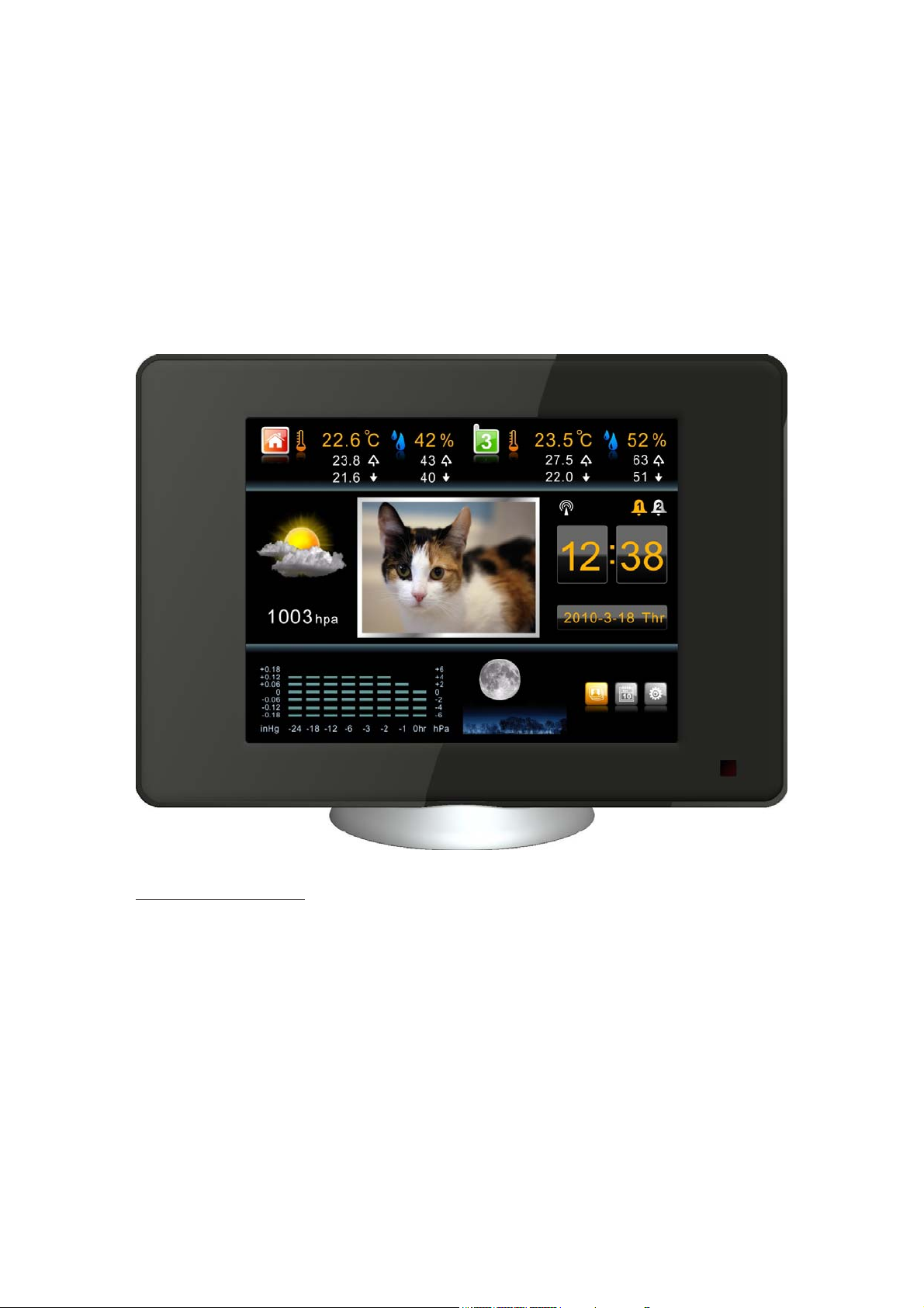
FUNCTIONS OF THE WEATHER STATION
This product measures the environment of its surrounding area and receives weather
data transmitting from up to five outdoor sensors for temperature and humidity. The data
is continuously updated to bring you the latest weather information displayed on the 8
inches TFT color display of the receiving unit. Its wireless 915 MHz can transmit data over a
distance of 100 feet in open space.
FEATURES:
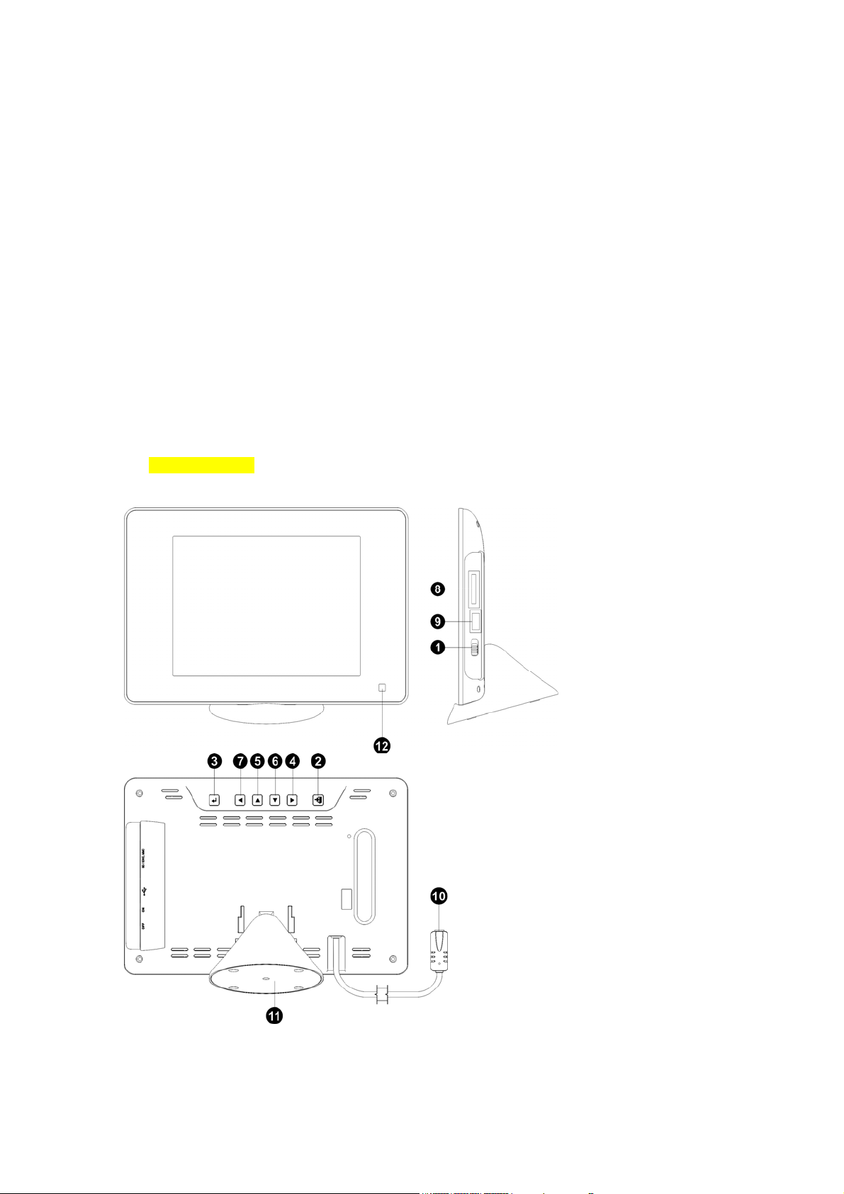
A. VIEWER UNIT
1. Button: Power Key
Main switch for power ON-OFF and press this SWITCH to enter standby mode.
2. Button: Exit Key
Press this EXIT button to go back to the previous screen
3. Button: Enter Key
Press this key to confirm the setting
4. Button: ‘Left’ Key
Navigation button for left-direction
5. Button: Up Key
Navigation button for up-direction
6. Button: Down Key
Navigation button for down-direction
7. Button: ‘Right’ Key
Navigation button for right-direction
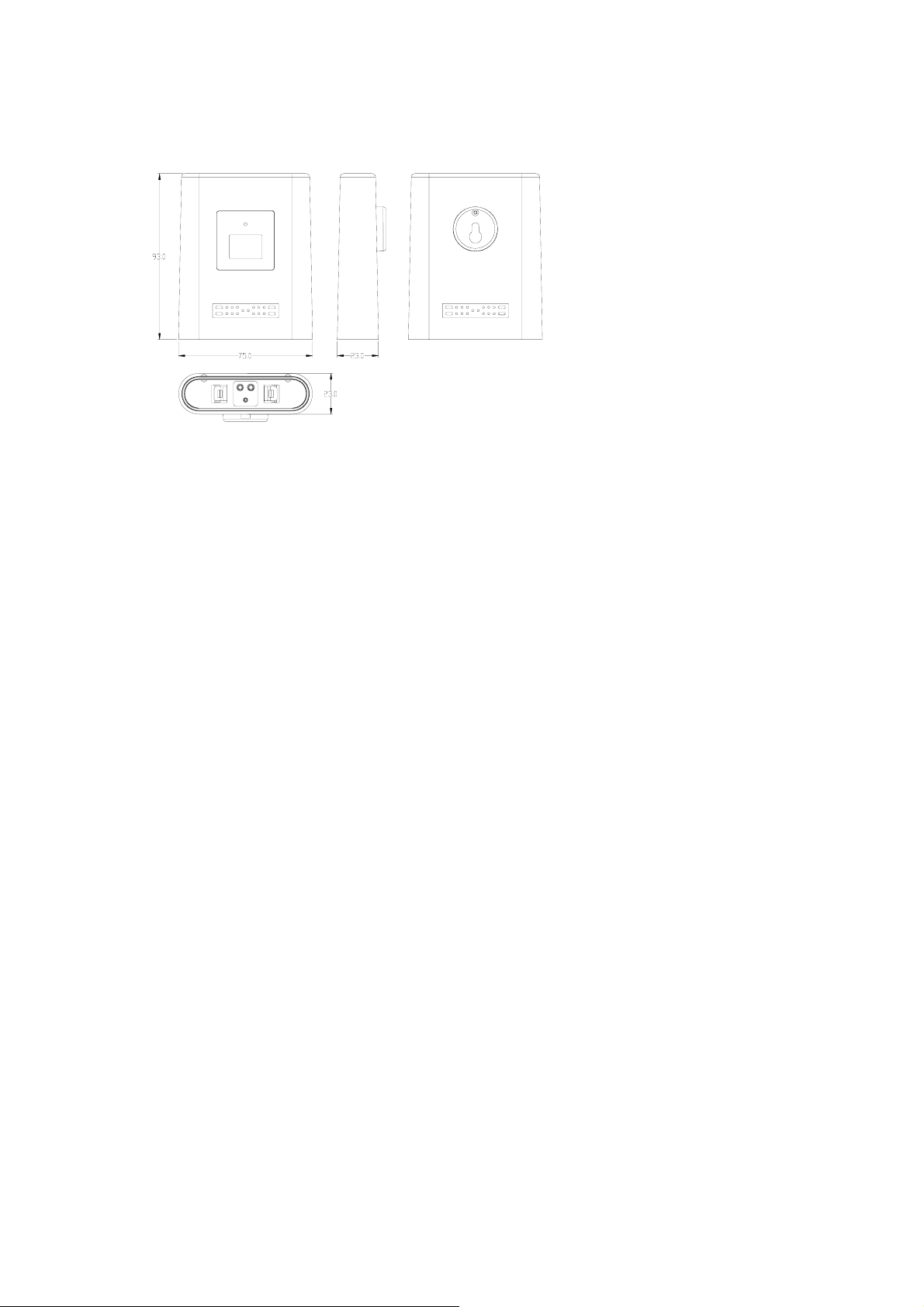
10. Power socket
Power socket for external AC/DC power adaptor
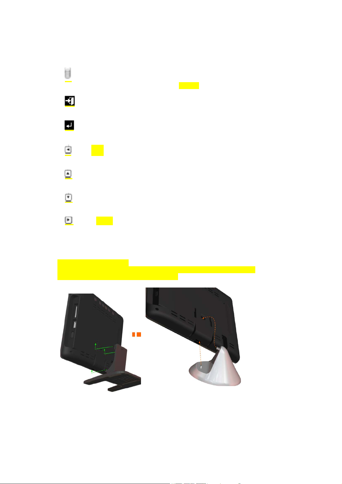
11. The detachable stand
Two kinds of detachable stands can be optional for table top mounting.
Please see the pictures below for installation:
12. IR sensor
It is the IR sensor port to receive IR signal from the handy IR remote
13. Card cartridge
These are the card slots for memory card
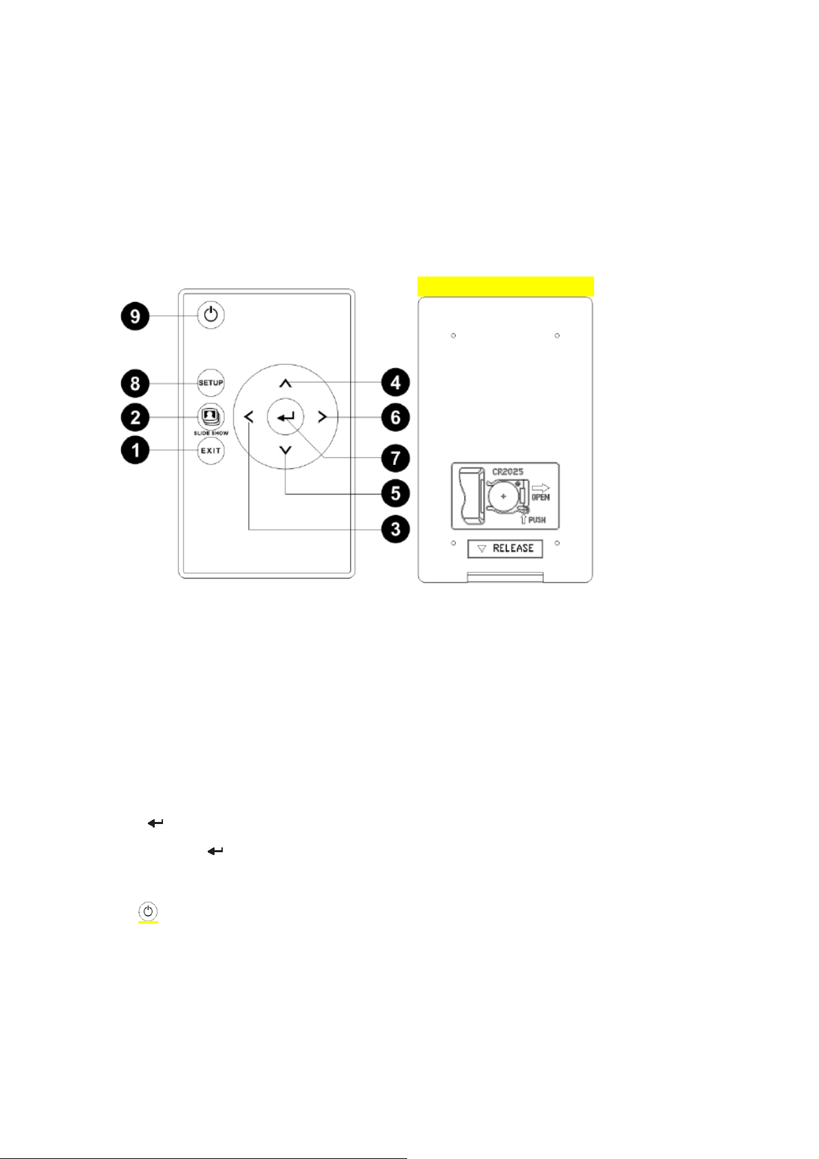
B. IR REMOTE CONTROL UNIT
Description of Buttons
1. [EXIT] button
Press this ESCAPE button to go back to the previous screen
2. [SLIDE SHOW] short cut button
Press to go straight into the Slide Show mode.
3. [◄] button
Navigation button for left-direction
4. [▲] button
Navigation button for up-direction
5. [▼] button
Navigation button for down-direction
6. [►] button
Navigation button for right-direction
7. [
8. [SETUP] button
9. button
C. OUTDOOR REMOTE THERMO-HYGRO SENSOR
] button
Press this [
Press this key to enter setting mode.
Press to turn ON/OFF the display screen
] button to confirm
1. LED indicator
Flashes when remote unit transmits a reading.
2, 3. Temperature & Humidity display
LCD Displays for temperature and humidity readouts.
4. Channel number
Indicates the remote sensor is set to which channel and the user can find the
corresponding reading in the same channel in the linked receiving unit.
5. Battery compartment
Description of Buttons
The remote sensor has 3 function buttons inside the battery compartment (5).
6. [CH] button
After the battery installation, the Channel No. blinks slowly every 1.5 seconds to
indicate it is now under
channel setting mode and is set to Channel 1 by default. If the user presses no key
within 10 seconds, the unit will auto-exit the channel setting.
If the user press [CH] button once during the channel setting, the Channel No. will blink
twice every 1.6
seconds to indicate the unit is set to Channel 2. If the user press [CH] button again, the
channel number will be advanced to Channel 3 and the Channel No. will blink 3 times
and so on.
The maximum channel number is ‘5’ and the unit will be scrolled back to Channel ‘1’
at the 5th press
of the [CH] button.
7. [°C/°F] Button
Press to toggle unit °C(Centigrade) or °F(Fahrenheit).
8. [RESET] Button
Press to hardware reset the unit to factory setting
 Loading...