

Page 1
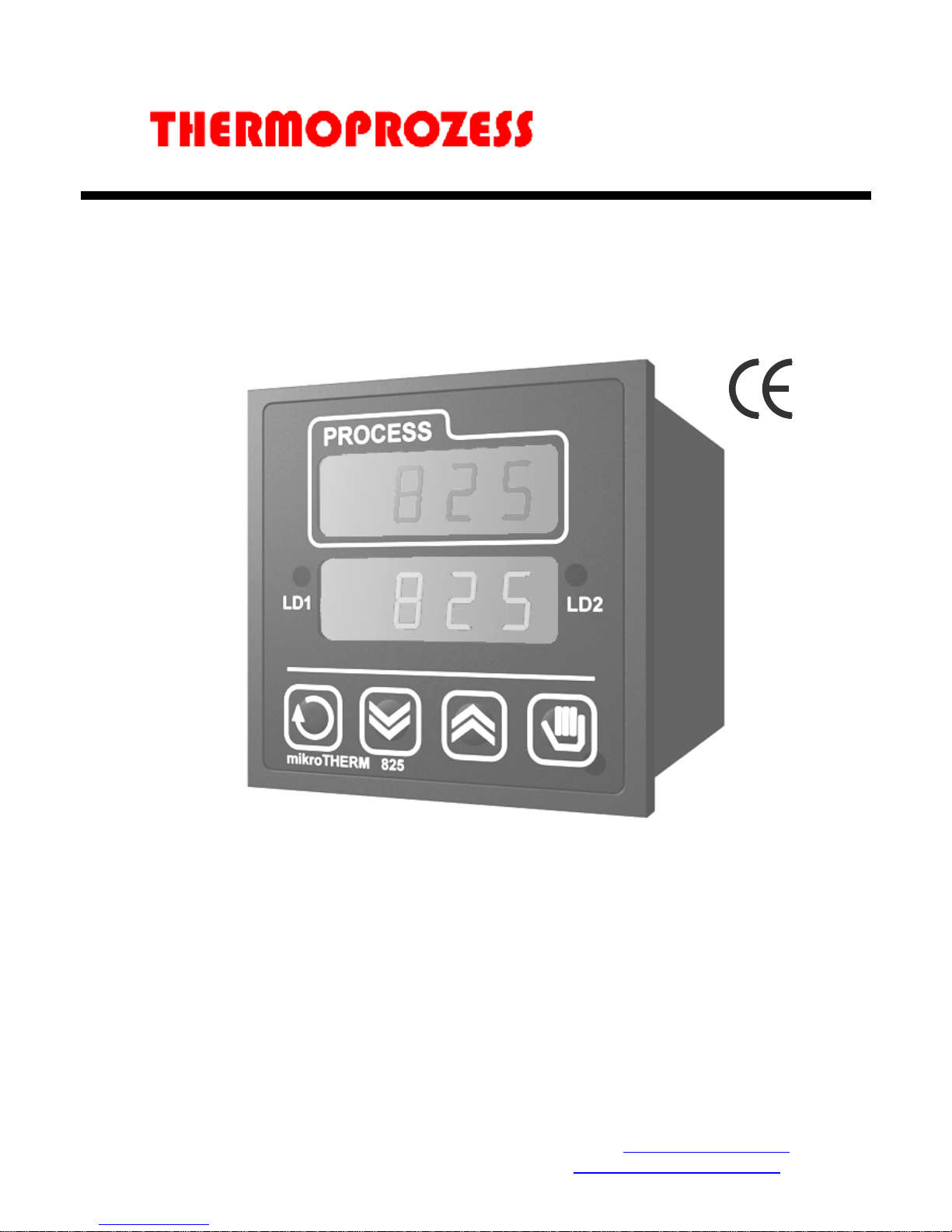
MIKROTHERM® 825
MT825-A, controller
user´s manual
MT825A 11/09 Rev.7/Soft.4.3
THERMOPROZESS s.r.o.
Riegrova 2668/6c
370 01 České Budějovice
Czech Republic
Tel.: +420 387 313 182
Fax: +420 385 340 947
E-Mail: info@thermoprozess.cz
http://www.thermoprozess.cz
Page 2

2
If there is any default of the device could cause a damage,
the equipment with the controller must be fitted with the
independent protection unit (thermal cut-out/limiter).
Page 3

User part
3
1 Introduction
MIKROTHERM® MT825-A is ¼ DIN temperature/process controller with 1 input for
measurement, 1 input/output for controlling and 5 outputs ( thi first is for control, the second
is for alarm/signal, the event output 3,4,5).
• Buying a new controller, see the chapter Installation and configuration of controller.
• If you have the device installed from the producer of device, see the chapter Final User.
Final User
If you are a final user, you will get the device in the customised operation and you can view
and change only the parameters, you need for your own work. There is a special part for you
in manual – User Part.
If you are a new user of the device, focus on the following chapters:
• Basic terms, it is explained the key functions, modes of controller, info ans error
massages.. In the whole manual you will be referred to the terms expalined in this chapter.
• User level, in this level you can scroll through mode of controller, edit programmes, start,
stop and end programmes…
• If you want to create programme profile, you will find the information in chapter
ProF, creations of programme profiles. Programme profile means to create the structure
of programme (1.step – rate at set temperature, 2.step soak at this temperature…) and
only some parameters can be made accesible. The result is that during editing programmes
you will set just a few chosen parameters ( final temperature of 1.step, time of 2.step)
• Tips for operation and troubleshooting you will find in the chapter Tipps..
Installation and configuration of controller
For installation and controller configuration is determined configuration and service part of
manual.
It is assumed that you know basic operation of device described in the chapter Basic terms
and you are authorised for installation and you know how to set up the device.
• Information on installation of device you will find in chapter Installation.
• Wiring is described in chapter Power wiring..
• For further information on operation see chapter Configuration level and Tips for
configuration.. For service worker it is convenient to find out options in chapter Service
level. After the operation of device it is recommended to write down parameter values in
table on page 53 There is a blank table for writting of programmes on the same page.
• You will find the information on editing, starting and ending of programmes, viewing and
setting of parameters, etc.., in operation part of the manual.
Important:
The description of serial communications is not stated in this manual. It is stated in the
manual for the devices fitted with communications board.
Page 4
User part
4
2 Basic terms
The controller cna be used for control of temperature or other quantity (for simple description
the temperature will be used) according to set profile. To avoid problems in operation of
device the user must be able to manage its operation.
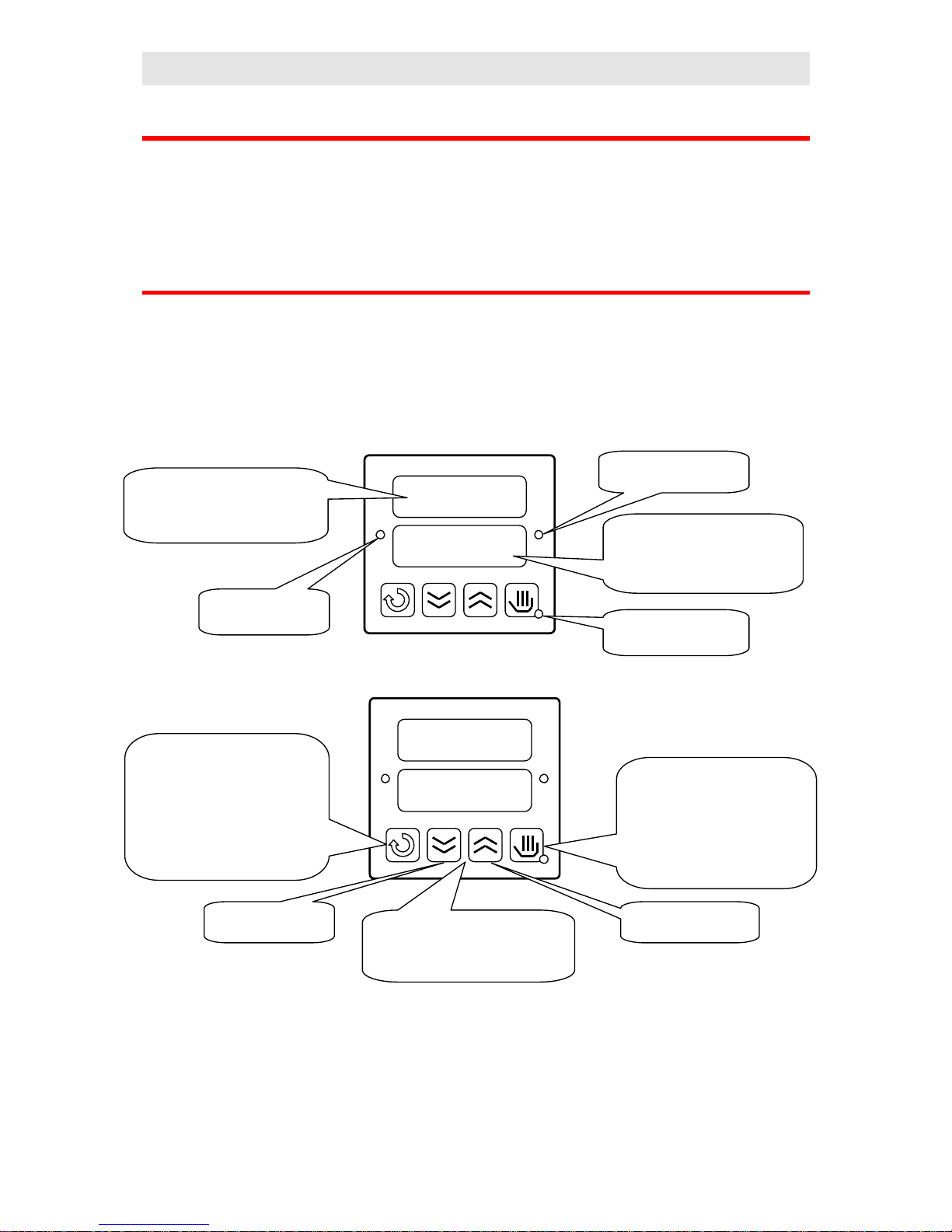
2.1 Operation and description of the controller
Before you start, it is necessary to explain the principals for control.On the front panel board
you can see 2 displays, 3 control lights and 4 keys. The device is set and configured via menu.
The features of keys and displays is shown on the following pictures:
The tables for menu and descriptions of parameters are in the following chapters.
Lower display
Upper display
•
Indicates actual process value
• at setting it shows parameter
value
•
Indicates set point value
• At setting shows type of
parameter
Indicates the state of
controller output
Indicates alarm/signal
output
Diode MODE indicates
mode of device
functions of indicators
Lower display
Upper display
Short-term press:
• listing in menu
• confirm of set values
• return from menu at start /
end
Long-term press -3 seconds):
• editing of programme
Short-term press:
• Starting, ending programme
Long-term press:
• Setting of programme and
time for starting programme
by the lock
decreasing of set
value
increasing of set value
Press 2 keys together (for 3 seconds)
to change levels from lower to higher
levels (user, configuration, service)
key functiones
Page 5

User part
5
Settings parameters
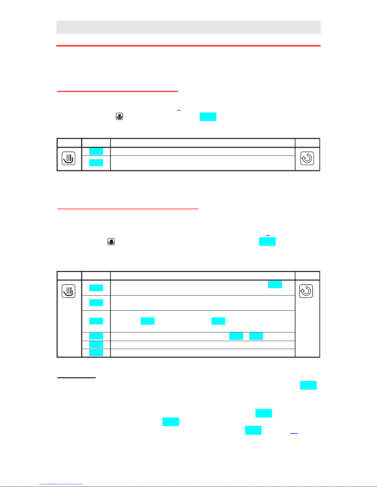
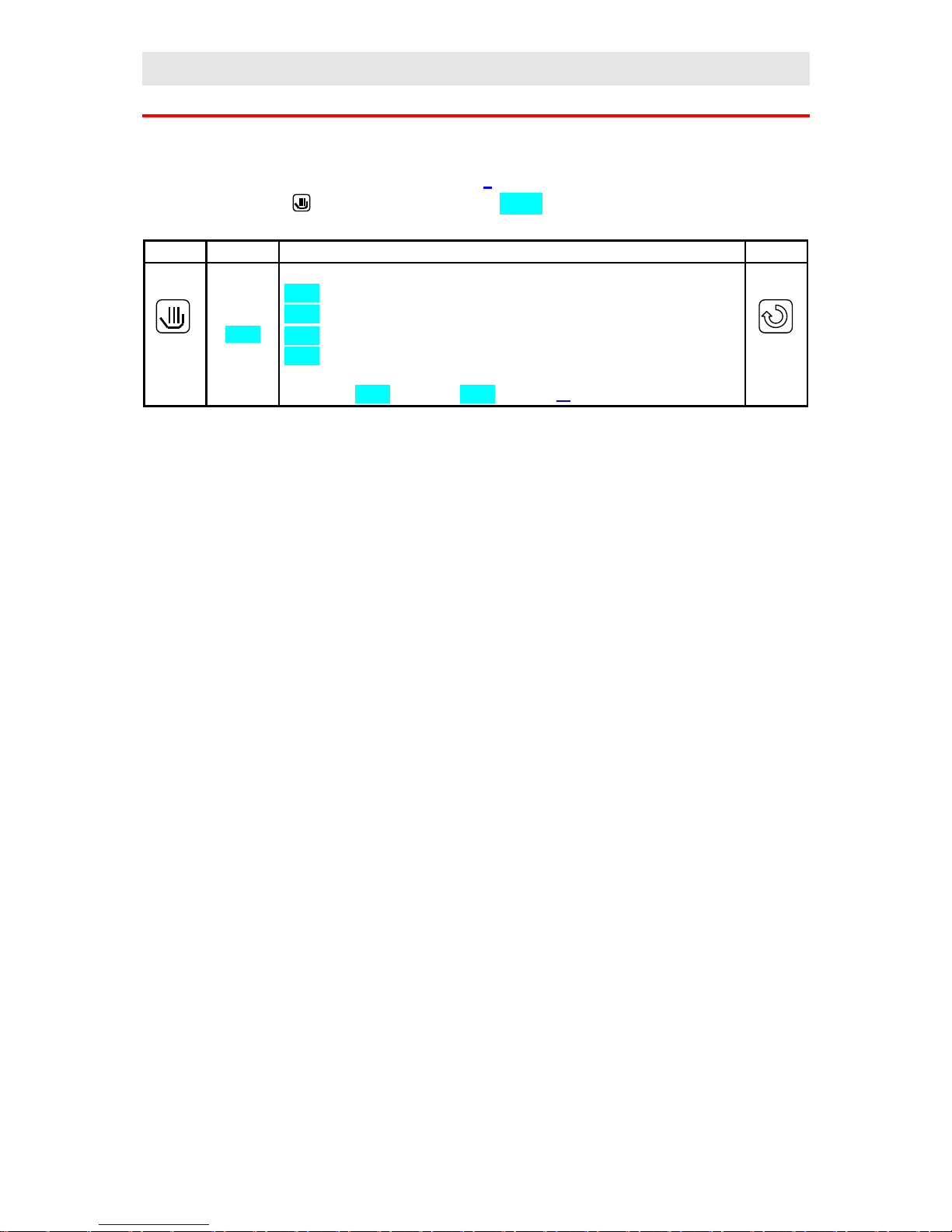
In the user part the setting of parameters is described in the table of this format:
Confirm Display Procedure Return
• Confirm, indicates the key, with which you go through menu and confirm set parameters
• Display, show the data displayed on lover display
• Procedure, meaning of parameter and procedure how ti set it
• Return, return to basic mode without editing the parameter
Important:
• Parameters are selected with arrow keys
• If the parameter is not confirmed by the key stated in column Confirm, it is not set
• Returning to basic mode by the key Return, then the parameter is not set
• During automatic return to basic mode the parameter is not set. The controller returns to
basic mode automatically if no key is pressed for 60 seconds and automatic return is
allowed (in konfiguration level, menu SYS, parameter Aret=on)
2.2 Modes of controller
Mode of controller is indicated by diode MODE, see page 4. The 3 following modes will be
often used in the description of controller.
• Basic, diode MODE is not lit, controller output is OFF or ON/OFF control switches
output depending on set value. If you set parameters you return by pressing to basic
mode or by pressing if you edit the start/end of programme.
• Running a programme, diode MODE is lit, the controller runs by programme
• Setting, diode MODE blinks, parameters are set.
2.3 Information and error messages
Information and error massages are indicated only in basic mode.
Information messages, upper display
• ---- … error of input sensor or input is not set.
Page 6

User part
6
Information messages, lower display
• PCLK … starting a programme by the clock, see page 15..
• Aut1 … automatic setting/autottuning of PID parametrs Pb1 It1 dE1, see page 26.
• Aut2 … automatic setting/autottuning of PID parametrs Pb2, It2, dE2, see page 26.
• Gsd … guaranteed soak deviation GSD, process value leaves the defined Soak Band,
page 22.
• trun … indicates time-limited running of controller, see page 27.
• hoLd … indicates mode of controller during programme running after the supply voltage
interruption or after setting from keyboard, see page 22. The programme is interrupted
and the last set value is retained.
• Abrt … indicates mode of controller during programme running after supply voltage
interruption or after setting keyboard, see page 22. The programme is interrupted and
controller output is switched OFF.
• hISt … indicates the browsing on data history, see page 25.
Error messages, lower display
• Err0 … error in EPROM. Switch the controller OFF and ON again. If the problem
persists, contact your supplier.
• Err1 … error in EEPROM, configuration and operation parameters. The troubleshooting
error (restart of parameters and subsequent configuration) can be made only by
experienced user. If the trouble persists, contact your supplier.
• Err3 … error in A/D converter. It can be caused by electrical impulse at input, too low
temperature and excessive humidity…. Switch the controller OFF and ON again. If the
problem persists, contact your supplier.
Page 7
User part
7
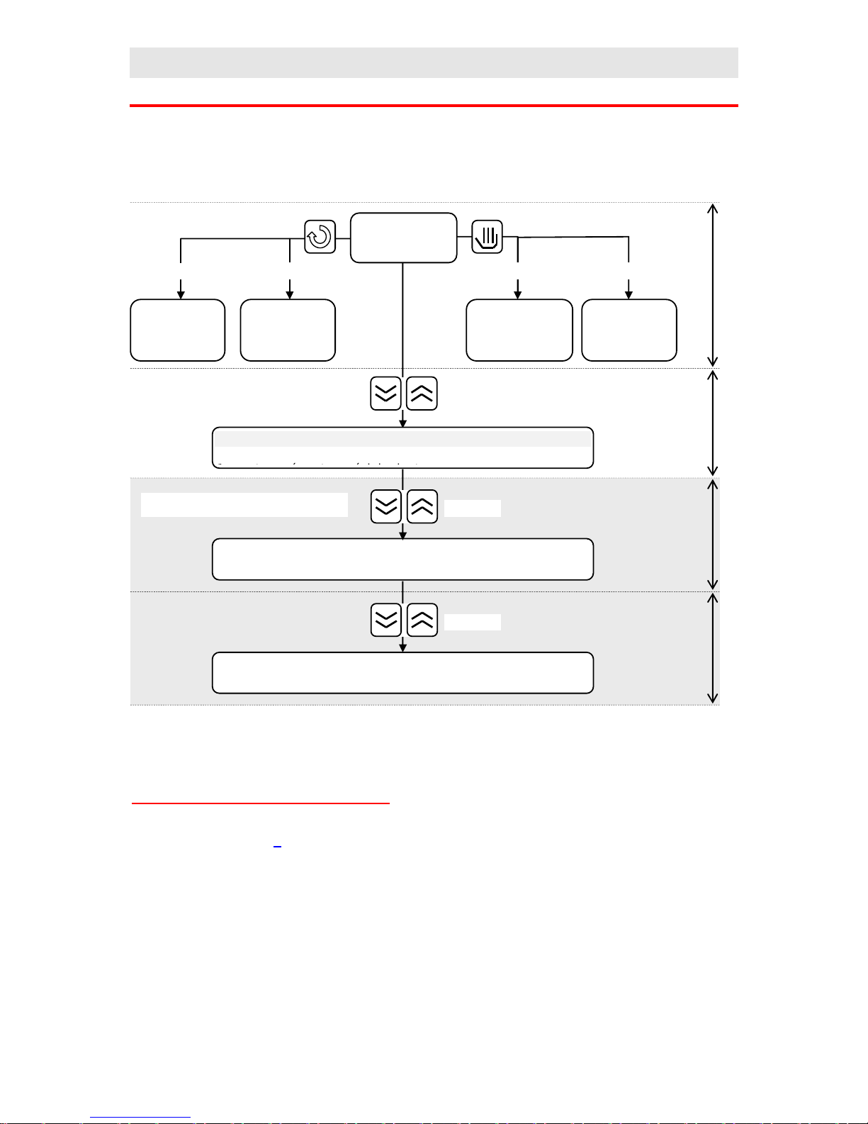
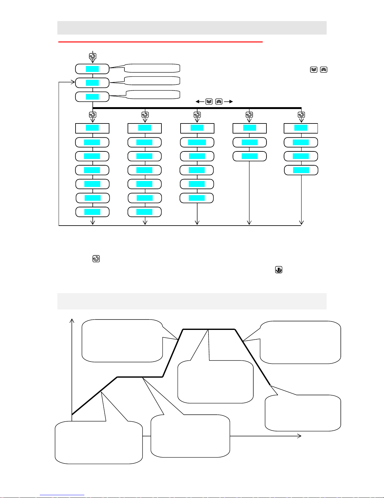
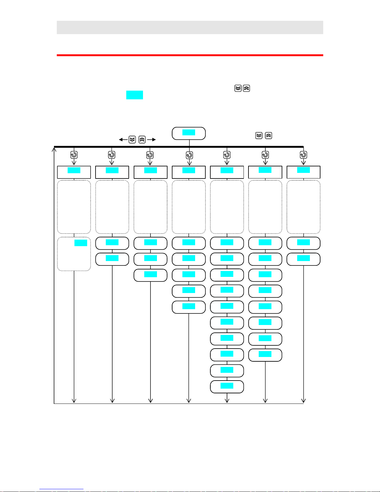
2.4 Overview of levels, menu
Total overview of programme levels and menu is shown below. The entry to menu is
indicated by the keys, long-term press is approximately 3 seconds.
Using of single menus and levels:
• User menu enables the quickest acces for user. The list of parameters in menu can be
selected, see page 8
• Programme menu is used for editing and viewing programmes.
• Start and end of programme, in this menu you can start, interrupt and end up
programme via keyboard.
• Starting programme by the internal clock, setting of programme number and time of
start.
• Operation level is accesible for user after setting of all necessary parameters. Most of
menu in user level can be inhibited (denied) to user.
• Configuration level is intended for configuration of device. In this level you can set most
of parameters of operation level. It is recommended to lock the menu after setting.
• Service level provides you with parameters for servicing.
Basic mode
User menu
Programme
menu
Start, interupt
and end
programme
Starting
programme
by clock
Short press Short press Long press
Long press
Operation level
Configuration level
Service level
Long press
Long press
Long press
User level
Operation
level
Configuration
level
Service level
Only for experienced user
Page 8

User part
8
3 User level
In this level you can access promptly to most common parameters. It consists of the following
menus:
• User menu, enables access to most applicable parameters of device. Their specification
and sequence can be set.
• Programme menu is intended for editing, monitoring and reading programmes.
• Start, interruption and end of a programme.
• Starting a programmme by the internal clock.
3.1 User menu
In user menu you can set and view the parameters of the controller. You can choose and set
the list of parameters and their sequence that will be in user menu.
• The controller is in basic MODE or in running a programme, see page 5. Upper display
indicates process value, lower display indicates set point value.
• By pressing key you can scroll through user menu.
Important:
• The tables shows parameters that can be accesible in user menu. Each parameter in this
menu can be permitted or not for the operator and the operator has only important
parameters available.
• The sequence of parameters is optional and can be set.
Page 9
User part
9
Confirm Display Procedure Return
trun
Work of controller is time limited. See details on page 27.
hISt
Reading of measured values from history. If you like to read measured/process values,
set YES and confirm. Upper display indicates process value, lower one time in format
hour.minute. Scroll through values with arrow keys.
Prog
On display appears number of actual programme in running.
StEP
On display appears actual step of programme.
EnSP
On display appears final set point value of actual step
trEM
Time to the end of actual step in format hours.minutes, if time is longer than 99 hours
then only in format hours.
CLK
Menu for setting real time clock.
• YEAr … set actual year
• Mon … set actual month
• dAY … set actual day
• hour … set current hour
• Min … set current minute
Pcnt
Shows instantaneous power in %
Ptot
Shows total power consumed in kWh
PPGM
Shows consumed power during the last programme in kWh
o2oF
Switch OFF permanent alarm/ signalling by setting YES and confirm..
Ent1
Indicates the state of event output 1 ( oFF, on). The output can be set by
arrowkeys only if programme does not run.
Ent2
Indicates the state of event output 2 ( oFF, on). The output can be set by
arrowkeys only if programme does not run.
Ent3
Indicates the state of event output 3 ( oFF, on). The output can be set by
arrowkeys only if programme does not run..
Aut
Sarting ( on), stopping ( oFF) of autotuning/automatic setting of PID parameters.
CAL1
Calibration of sensor. Set value is added to process value.
hPEr
Period for measured values storing (hISt) in minutes
hSto
Condition for data storing:
• oFF, storing is turned OFF
• ProG, storing is executed only if programmme runs
• ALSG, storing is executed only at alarm/signalling
• Cont, storing is executed constantly
PPEr
Period of printing in minutes
PSto
Condition for printing
• oFF, printing is turned OFF
• ProG, printing is executed only if programme runs
• ALSG, printing is executed only at alarm/signalling
• Cont, printing is executed constantly
Page 10

User part
10
3.2 Programme menu
In controller 30 user programmes can be stored numbered with 1 up to 30 and another 4
Steady fixed set programmes labelled FP1 – FP4, see page 23
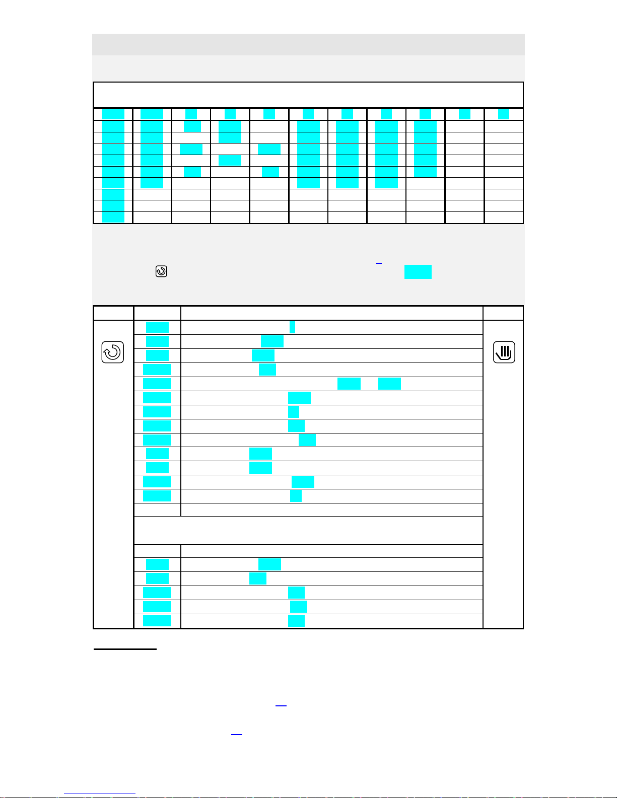
Each programmme consists of steps (max. 15). Types of steps are illustrated in the picture.
Each step is defined with parameters appearing on lower display in format AA.xx, where AA
means type of step and xx number of step. For example SP.11 means set point value of 11.
Step. Types of steps follows:
StPt, ramp rate up or down of set point value
Summary of parameters of step StPt
Dispaly Meaning
SP.xx
Final set point value.
tI.xx
Time needy for reaching set point value, is stated in format hour.minutes.
E1.xx
State of event output 1, see page 23
E2.xx
State of the event output 2.
E3.xx
State of the event output 3.
Gd.xx
Guaranteed soak deviation GSD, see page 22
Setpoint
value
temperatur
tim
Rate up or down StPt, rAtE
In real defined time:
• StPt, is defined by final temperature and
time needy for reaching final temperature.
• rAtE, ramp up or down is defined by final
temperature and ramp rate in (unit/hour)
SoAK
Set point value is not changed during the
step. Is setting soak time.
JuMP
Enables jump at:
-Another step in the
programmme that runs
-Another step of other
programme oothotherpr
End
Ends of programme
SP.xx
(°C)
tI.xx
(hour.min)
Set point
value
time
Page 11
User part
11
Initial set point value in step StPt in the same as the final set point value of preceding
(former) step. In case of starting a programmme the initial set point value is equal to the
process value.
Time for step is max. 99 hours 59 minutes.
rAtE, ramp rate up or down of set point value
Summary of parameters of step rAtE
Display meaning
SP.xx
Final set point value
rt.xx
Speed of rate to set point value is stated in format °C/hour
E1.xx
State of event output 1, see page 23.
E2.xx
State of event output 2
E3.xx
State of event output 3
Gd.xx
Guaranteed soak deviation GSD, see page 22
Initial set point value in step rAtE is the same as the final set point value of preceding /
former step. In case of starting a programme the initial set point value is equal to the process
value. Duration of step is not limited.
SoAK, soak on set point value
SP.xx
(°C)
rt.xx
(°C/hour.)
Set point
value
time
tI.xx (hour.min)
Set point value
time
Page 12
User part
12
Summary of parameters of step SoAK
Display Meaning
tI.xx
Time of soak is stated in format hour.minutes
E1.xx
State of event output 1, see page 23.
E2.xx
State of event output 2.
E3.xx
State of event output 3.
Gd.xx
Guaranted soak deviation, see page 22
Set point value in step SoAK is the same as the final set point value of preceding (former)
step. In case of starting programme the set point value is equal to the process value.
Time for step is maximum 99 hours 59 minutes.
JuMP, jump in programme
Summary of parameters of step JuMP
Display Meaning
JP.xx
The number of programme to be jumped at.
JS.xx
The number of step to be jumped at.
If you create endless programme loop (jump at the same place), the programme will be ended
up.
End, ending a programme
Summary of parameters of step End
Display Meaning
E1.xx
State of event output 1, see page 23.
E2.xx
State of event output 2.
E3.xx
State of event output 3.
Step End ends up the programme and sets event outputs.
set point
value
time
set point
value
time
Page 13
User part
13
Complete menu for editing a programme is ilustrated below:
• To enter menu editing and reading a programme from basic MODE press for more than 3
sec. key .
• To return from menu for editing a programme to basic MODE press key .
Example:
Now you are able to edit your own programme as you know all the types of steps. The
following example clarifies editing a programme. This profile you like to edit on position 5.
set value
point
time
Step 1
• ramp rate at set point value
200°C in 2 hours 30 min.
• event outputs see table
• guaranted soak deviation is OFF
Step 2
• soak 1 hour. 20 min .
• event outputs see table.
• GSD turn ON on start
Step 3
• ramp at set point value
1050°C rate 250°C/hour.
• event outputs see table.
• guaranted soak deviation is
Step 4
• soak 2 hour 10 min .
• event output see table
• guaranted soak deviation
is ON in whole period
Step 5
• ramp down at set point value
150°C at rate 150°C/hour
• event output see table
• GSD is OFF
Step 6
• ending a programme
• event outputs see the table
ProG
StEP
tYPE
StPt
SP.xx
tI.xx
E1.xx
Gd.xx
rAtE
SP.xx
rt.xx
E1.xx
Gd.xx
SoAK
tI.xx
E1.xx
Gd.xx
JuMP
JP.xx
JS.xx
End
E1.xx
set number of programme
set number of step
set type of step
E2.xx
E3.xx
E2.xx
E3.xx E2.xx
E3.xx
E2.xx
E3.xx
Page 14
User part
14
You can write down the profile to table:
Progr: 5
StEP tYPE SP TI rt E1 E2 E3 Gd JP JS
1 StPt 200 2.30
oFF on oFF oFF
2 SoAK
1.20
on on oFF Strt
3 rAtE 1050
250 on on On oFF
4 SoAK
2.10
on oFF oFF on
5 rAtE 150
150 oFF oFF oFF oFF
6 End
oFF oFF oFF
7
8
9
Now edit the programme to the memory of controller:
• Controller is in basic MODE or in a programme, see page 5
• Press key for more then 3 seconds. On lower display appears ProG, and then you can
proceed acc. the table below:
Confirm Display Procedure Return
Prog
Number of programme, set 5
Step
Number of step, set 1
tYPE
Type of step, set StPt
SP. 1
Set point value, set 200
tI. 1
Time needy for reaching set point value SP 1, set 2.30
E1. 1
State of event output 3, set oFF
E2. 1
State of event output 2, set on
E3. 1
State of event output 3, set oFF
Gd. 1
Guaranted soak deviation, set oFF
StEP
Type of step, set 2
tYPE
Type of step, set SoAK
TI. 2
Time to the end of soak, set 1.20
E1. 2
State of event output 1, set on
Proceed in editing another parameters in the same way up to step 6
StEP
Number of step,set 6
tYPE
Type of step, set End
E1. 6
State of event output 1, set oFF
E2. 6
State of event output 2, set oFF
E3. 6
State of event output 3, set oFF
Important:
• You need not always set all steps, which is time consuming and tiresome in most cases. In
that case you can create your own profile of programme (some parameters can be set
permanently, they will not be displayed). You will find all necessary information how to
make a programme profile on page 18.
• If you edit the same or similar programmes with different parameters, you can easily copy
the programmes, see page 19.
Page 15
User part
15
3.3 Starting a programme
The programme can be started up by the command of operator with keyboard or can be
automatically started up by the internal real time clok.
Starting a programme with keyboard
• Controller is in basic MODE, see page 5.
• Press shortly key . On lower display appears ProG, another procedure see table:
Confirm Display Procedure Return
ProG
Set number of programme you wish to start up.
StEP
Set step from wich you like to start programme. If it is not configured, the
programme starts up from step 1.
Starting a programme by the internal clock
You can select the programme that will be started up by the clock after time setting.
• The controller is in basic MODE or running in a programme, see page 5.
• Press the key for more then 3 seconds. On lower display appears PCLK, then proceed
acc. to the table:
Confirm Display Procedure Return
PCLK
Set number of programme you wish to start up by clock. If you set oFF,
automatic start is not alloved.
SCLK
Set step from wich you like to start programme. If it is not configured, the
programme starts up from step 1.
Mon
Set month of start of programme. If you don´t liketo set month and day of
starting, set oFF. In that case parameter dAY is not displayed and
programme starts every day.
dAY
Set day of starting. It is not displayed, if setting is Mon = oFF.
hour
Set hour of starting a programme.
Min
Set minute of starting a programme.
Important:
• If you set the automatic starting a programme by the clock, on lower display blinks PCLK
in basic menu.
• You can not set the automatic starting a programme if another programme runs.
• If the programme starting up by the clock is shorter than parameter tdEL, it can be started
many times in a series. Parameter tdEL means time duration in minutes in which you can
start programme. You will find it in configuration level, menu Prun, see page 37.
Page 16
User part
16
3.4 To hold, to continue with and to end a programme
You can hold or end a programme or you can continue with it:
• The controller is in a programme, see page 5..
• Press shortly key , on lower display appears ProG, then proceed acc. to table:
Confirm Display Procedure Return
ProG
Set the state of the controller:
Cont … programme continues
hoLd … programme is held and the controller retains the last set point value
Abrt … programme is held and the control output is turned OFF.
End … programme is ended up
Not all options can e offered. Setting can be performed in configuration
level, menu Prun, parameter StoP, see page 37.
Page 17
User part
17
4 Operation level
In this level you can set parameters which are available to user.
To enter the menu from basic MODE press for 3 seconds key
On lower display blinks oPEr, set requested menu on upper display. Not all menus are
accesible.
oPEr
Editing of
programme.
profiles,
creating
programme
profiles
ProF
Menu
ProF
see below
FroM
Copying
programme
profiles
PCPY
to
Monitoring
actual power
and
consumed
energy
MonI
PCnt
Ptot
PPGM
Setting
internal time
clock
CLK YEAr
Mon
dAY
hour
Min
Start up
autotuningu,
state event
output, period
data history
…
GLbL
o2oF
Ent1
Aut
CAL1
hPEr
hSto
PPEr
PSto
Setting PID
parameters of
first output
out1
Pb1
It1
dE1
Pb2
It2
dE2
Ct1
hYS1
Setting
alarm/signal
limits of
second output
out2
o2Lo
o2hI
Ent2
Ent3
Set value parameters with
arrow keys
Page 18
User part
18
4.1 ProF, creations of programme profiles
If you edit a programme, as described in chapter Programme menu, you must go through and
edit all steps. But you can have a programmme, where you need to change only a few
parameters.Then it is convenient to create a programme profile.
Before the explanation how to create a profile it is necesarry to clear up 2 terms, full and
shortened edit of programme.
Full edit of programme
To create a profile you will set full edit of programme in operation level, menu ProF,
parameter EdIt = FuLL. Editing a programme parameters StEp (number of step) and
tYPE (type of step) are displayed. When create programme profile some parameters can be
firmly set. and tey are not displayed during editing. The procedure for editing a programme
cerresponds to procedure described in the chapter Programme menu.
Shortened edit of programme
To create a profile set shortened edit of programme in operation level, menu ProF, parameter
EdIt = Shot. Parameters StEp (number of step) a tYPE (type of step) are not displayed
when you edit. It is possible to view and set only accesible parameters of programme. The
best thing how to see shortened edit is to view some of fixed programmes ( FP1, …).
Example – how to create a programme profile:
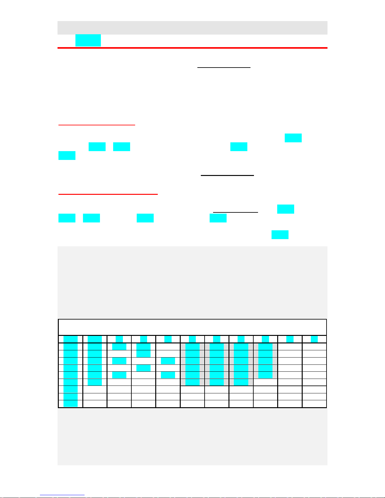
You want to create profile of programme no. 5 for shortened edit.
First work out the table of programme and highlight the parameters to be hidden (grey in the
table), ie. they are set just right at creating a profile:
Prog: 5
StEP tYPE SP tI rt E1 E2 E3 Gd JP JS
1 StPt 200 2.30
oFF on oFF oFF
2 SoAK
1.20
on on oFF Strt
3 rAtE 1050
250 on on On oFF
4 SoAK
2.10
on oFF oFF on
5 rAtE 150
150 oFF oFF oFF oFF
6 End
oFF oFF oFF
7
8
9
Page 19

User part
19
Now start editing a programme profile:
Confirm Display Procedure Return
Prog
Number of programme, set 5
Edit
Full/ shortened edit of programme. Set shortened edit Shot
Step
Number of step, set 1
tYPE
Type of step, set StPt
SP. 1
Editing is allowed. This parameter is accesible, set EdIt
SP. 1
Set point value, set 200
tI. 1
Editing is allowed, set EdIt
tI. 1
Time needy for reaching set point value SP 1, set 2.30
Et. 1
If the parameters are not accesible you can allow the editing of all event
outputs, set SEt
E1. 1
State of event output 1, set oFF
E2. 1
State of event output 2, set on
E3. 1
State of event output 3, set oFF
Gd. 1
For editing to be allowed, set SEt
Gd. 1
Guaranteed soak deviation to be turned OFF, set oFF
StEP
Number of step, set 2
tYPE
Type of step, set SoAK
tI. 2
For editing to be allowed, set EdIt
tI. 2
Time to the end of soak, set 1.20
Et. 2
You can allow the editing of all event outputs by setting SEt
E1. 2
State of event output 1, set on
Proceed in editing another parameters in the same way up to step 6
StEP
Number of step, set 6
tYPE
Type of step, set End
Et. 6
For the permission ef editing of all event outputs, set SEt
E1. 6
State of event output 1, set oFF
E2. 6
State of event output 2, set oFF
E3. 6
State of event output 3, set oFF
To return to basic menu press the key
You can view the outcome in Programme menu.
4.2 PCPY, how to copy programmes
You can make your editing programmes easy with this menu. If the programmes are the same
or similar, you can create one programme that can be copied to the positions of another
programmes. Those programmes can be changed by your request.
You can also use steady fixed set programmes fo copying (FP 1, FP 2, …)
When you copy proceed as follows:
Confirm Display Procedure Return
FroM
The number of the source programme, ie. where it will be copied from..
Range: 1 to 30, FP 1, FP 2, FP 3, FP 4.
to
The number of the destined programme, ie. where it will be copied to.
Range: 1 to 30.
Page 20

User part
20
4.3 MonI, monitoring of power and consumption
In menu you cand find out the actual supplied power and the consumption of electrical energy.
Confirm Display Procedure Return
PCnt
Actual supplied power in %.
Ptot
Total consumption in kWh. After reaching value 9999 the counter is reset and
starts counting from 0.
PPGM
Energy consumption in kWh for one firing. When in programme the counter
is set to 0 and counting of consumption starts from 0.
4.4 CLK, how to set the time clock
In this menu you can set the real time clock. The clock is not equipped with automatic changeover
from standard time to daylight saving time and back in turn.
Confirm Display Procedure Return
YEAr
Set actual year
Mon
Set actual month
dAY
Set actual day
hour
Set actual hour
Min
Set actual minute
4.5 glBl, global parameters
In this menu there are the parameters taht can not be inserted elsewhere or any menu is not created for
this parameters.
Confirm Display Procedure Return
o2oF
Turn OFF constant alarm/signalling by setting YES and confirm
Ent1
Appears the state of event output 1 ( oFF, on). The output can be set with arrow
keys if programme does not run.
Ent2
Appears the state of event output 2 ( oFF, on). The output can be set with arrow
keys if programme does not run.
Ent3
Appears the state of event output 3 ( oFF, on). The output can be set with arrow
keys if programme does not run.
Aut
Starting ( on), stopping ( oFF) the automatic optimalization of PID parameters –
autotuning.
CAL1
Calibration of sensor. Set value is added to process value.
Range: -999 to 999 °C.
hPEr
The period of data storing of measured process values(hISt) in minutes.
Range: 1 to 120 minutes.
hSto
Condition for data storing of measured process values ( data history)
• oFF, data storing is turned OFF
• ProG, storing is executed only if programme runs
• ALSG, storing is executed only alarm / signalling
• Cont, storing is executed constantly
PPEr
The period for priting protocol on printer in minutes.
Range: 1 to 120 minutes.
PSto
Condition for priting:
• oFF, printing is turned OFF
• ProG, printing is executed only if programme runs
• ALSG, printing is executed only if programme runs
• Cont, printing is executed constantly
Page 21

User part
21
4.6 out1, setting parameters of control output
Menu is intended for manual setting of PID parameters or for improving parameters with
regard to offset of controlling.
Confirm Display Procedure Return
Pb1
Proportional band, 1.set of parameters
Range: 1 to 2499 °C.
It1
Integral value, 1.set of parameters
Range: oFF, 0.1 to 99.9 minutes
dE1
Derivative value, 1. set of parameters
Range: oFF, 0.01 to 9.99 minutes.
Pb2
Proportional band, 2. set of parameters
Range: 1 to 2499 °C.
It2
Integral value, 2. set of parameters
Range: oFF, 0.1 to 99.9 minutes
dE2
Derivative value, 2. set of parameters
Range: oFF, 0.01 to 9.99 minutes
Ct1
Time cycle
Range: 1 to 250 seconds for ot1 = ht, CL, 5 to 250 seconds for
ot1 = ht2, CL2.
hYS1
Hysteresis, this parameter is set only for ON/OFF control..
Range: 1 to 249 °C.
Parameters Pb1, It1, dE1 / Pb2, It2, dE2 are switched over depending on set
point value.
Temperature for switching over is set in configuration level, menu SYS parameter PID2. If
the process value is lower than PID2, parameters Pb1, It1, dE1 take efect, if the
process value is higher than PID2 parameters Pb2, It2, dE2 take effect.
4.7 out2, alarm set points / signal set points
Alarm / signal set points take action when the process temperature leaves a defined range or
deviation from set point value is higher, see page 48.
Confirm Display Procedure Return
o2Lo
Low alarm / signal set points
Range:
• -499 to o2hI °C for ot2 = ALPr, SGPr
• -999 to 0 °C for ot2 = ALdE, SGdE.
o2hI
High alarm / siganl set points
Range:
• o2Lo to 2499 °C for ot2 = ALPr, SGPr
• 0 to 999 °C for ot2 = ALdE, SGdE.
Page 22

User part
22
5 Tips
In this chapter the tips for operating and setting of the controller and the troubleshooting some
problems are described for an operator.
5.1 Running of programme, option for operation
Running a programme is indicated by diode MODE (lit). On lower display appears set point value, on
upper display appears process value.
The operation options for setting and viewing the parameters, alter. state of controller are:
• Setting and viewing the parameters in user menu.
• Editing and viewing a programme. If you change parameters of the programme that is just
running, current running step is not changed. The new parameters are accepted only in the
following step..
• Setting automatic start up of a programme by the clock.
• Entry to operation menu, setting and viewing the parameters in menu.
• Interruption and ending of programme.
5.2 State Hold, Abort
Hold and Abort are states for interruption of programme than can be caused:
• By the interruption of supply voltage, see page 24.
• By the interruption of programme via keyboard, see page 16
In state Hold (on lower display blinks hoLd) the controller retains the last set point value. The
programme can be ended up by the operator or can continue, see page 16
In state Abort (on lower display blinks Abrt) the controller switches OFF control output. The
programme can be ended up by the operator or can continue, see page 16
5.3 Guaranteed Soak Devition - GSD
GSD limits the Soak Band about the set point value in which the set point value must be maintained.
If the process value leaves the defined Soak Band, counting down is paused..
You can use this for furnace where rapid ramp rate and soak is required. The function GSD will ensure
that the counting down of time for soak start after reaching the set point value in the function GSD is
defined for each step separately and it can be selected as follows:
• oFF, it is turned OFF for the step
• Strt, it is only turned ON at the beginning of the step
• on, it is turned ON within the whole . The width of GSD range can be set in
configuration level, menu Prun, parameter GSd
set point
value
time
Range
GSD
GSD
Page 23

User part
23
5.4 Event outputs
If the controller is fitted with event outputs, the states of the outputs can be
programmed( oFF ... turned OFF, on … turned ON). The state is set when editing a
programme in parameters E1. , E2. , E3. .
Viewing and possible setting of the event outputs is the following:
• When running a programme it is posible to view the states of event outputs with help of
parameters Ent1, Ent2, Ent3, setting can not be changed.
• When a programme does not run, you can view and set the states of event outputs via
parameters Ent1, Ent2, Ent3.
• Parameters Ent1, Ent2, Ent3 can be present in user menu or in operation level, menu
GLbL.
5.5 Fixed programmes
There are 4 steady fixed programmes stored in the controller´s memory. You can:
• view and use the programmes like model for editing your own profiles.
• Copy them to the position of vacant programmes (1 to 30) and then modify them by your
wish.
• Start them up, if your profile of programme fits.
Programmes are allocated behind the programme no. 30.
Programme FP1
Programme FP2
set point
value
time
160 °C
30°C/hour
20 min.
•
Event outputs are turned OFF
• Type of function GSD Strt
turnedON at beginning of 2.
step.
set point
value
time
1050 °C
360°C/hou
30 min.
•
Event outputs are turned OFF
• Type of function GSD Strt
turnedON at beginning of step
2. and 3.
200 °C
100°C/hour
Page 24

User part
24
Programme FP3
Programme FP4
5.6 Interruption of supply voltage
With this controller you can set the max. duration of the supply voltage interruption where the
programme still resumes / continues. If the duration of interruption is longer than this setting
of max. duration, it is possible to choose the following response of the controller:
• Resumes / continues in programme (Cont).
• Switches the control output ON/OFF at the last set point value, the possibility of resuming
in programme after operator´s action (hoLd).
• Switches OFF the control output, the possibility of resuming in programme after
operator‘s action (Abrt).
set point
value
time
1100 °C
•
Event outputs are turned OFF
• Type of function GSD Strt
turnedON at beginning of step
2. and 4..
360°C/hou
30 min.
200 °C
100°C/hour
30 min.
set point
value
time
800 °C
•
Event outputs are turned OFF
• Type of function GSD Strt
turnedON at beginning of step
2, 4, 6.
360°C/hou
30 min.
200 °C
100°C/hour
30 min.
180°C/hou
20 min.
1100 °C
Page 25

User part
25
Parameters for the definition of response to the supply voltage interruption:
• tCon, the permittrd duration of the interruption. Time is set in minutes.
• Pout, the response to the longer interruption of the supply voltage
The both parameters are palced in configuration level, menu Prun., see page 37.
5.7 Data history
The controller is fitted with the function for data storing of measured values. By the
configuration the controller can store 200 data in basic model or 5000 data in model with
expanded memory. If the memory is full, the oldest data are writen over with the newer ones..
Each stored record consist of the following items:
• measured process value
• month, day, hour and minute of record
How to read stored data – 2 ways:
• you can read stored data on display of controller in user menu, submenu hISt, (it must
be set accesible in configuration level). when you enter submenu (on lower display
appears hISt, on upper display set YES and confirm ) on upper display there is
measured process value indicated and time in format hour. minute appears on lower
display. Month and day can not be read on display. You can scroll between records with
arrow keys.
• the transfer of parameters via series communications. You will find out the necessary
informations in the manual describing communication.
Data storing can be set by these parameters:
• hPER, period of data storing in minutes.
• hSto, condition of storing. Data will be stored constantly, hSto = Cont, if alarm /
signal is active, hSto = ALSG, if programme runs, hSto = ProG, or data storing is not
set, hSto = oFF.
Both parameters are allocated in operation level, menu glBl, see page 20 or they can be set
accessible in user menu.
set point
value
time
device resumes in
programme
Permitted duration of
supply interruption
longer interruption
• resumes in programm
• the last set point value
• switches OFF output
Page 26

User part
26
5.8 Printing of measurement protocols on the printer
If the controller is fitted with series communications RS 232, the printer series input port can
be connected to the port/output of communications. The format of printing of measurement
protocol is illustrated below. The heading with the date is printed every day in 00.00 clock or
when the controller is turned ON. The set point and process value is always printed without
decimal point.
Parameters for printing of the measurement protocol:
• Prot = Prnt, setting of communications for control of printer. parameter is in
configuration level, menu CoM.
• PPER, period of printing in minutes
• PSto, condition for printing. Data will be printed constantly, PSto = Cont, data printing
if alarm or signal is active, PSto = ALSG, data printing if programme runs, PSto =
ProG, or printing is not allowed, PSto = oFF.
Both parameters are allocated in operation level, menu glBl, see page 20 or they can be
accesible in user menu.
5.9 Autotuning – automatic setting of PID parameters
The controller is fitted with the function that sets automatically PID parameters.
Procedure of starting autotuning:
• The controller must switch the control output, it means the control output must not be
turned OFF (in basic MODE there must not be on lower display oFF).
• Automatic optimalization you can start with parameter Aut = on. You will find
parameter in operation level, menu GlbL or you can set it accesible in user menu.
• The controller explores the characteristics of system from switching ON/OFF on the
output and determines optimal PID parameters. It can cause an overshoot.
• On lower disply blinks Aut1 or Aut2 depending on which set of PID parameters is set.
************************
DATE: 20.08.1999
************************
time: sp: c:
15:47 852 850
15:57 860 859
16:07 868 868
16:17 876 877
16:27 884
884
16:37 892 892
16:47 900 901
16:57 900 900
17:07 oFF 889
17:17 oFF 852
Page 27

User part
27
Important:
• Autotuning can not take effect in ON/OFF control, ie. ot1 = ht2 or CL2.
• Autotune set point value for autotuning is set by actual process value, by actual set point
value and by parameter AtSP. It is calculated this way:
autotune set poin value = actual process value + (actual set point value -
actual process value) x AtSP / 100.
• Parameters Pb1 , It1 , dE1 are set, if actual set point value is lower than parameter
PId2 when both sets of PID parameters are used(ALGo = PID2).
• Parameters Pb2 , It2 , dE2 are set, if actual set point value is higher than parameter
PId2.
Parameters AtSP, ALGo a PID2 are in configuration level, menu SYS, see page 37.
5.10 Time-limited work of the controller and its unlocking
You can set time-limited work of controllers for reason of servicing, etc. This state is
indicated in basic MODE by blinking trun. After elapsing the permitted time the starting
programmes is not allowed.
You can read the time to the end for working of the controller in parameter StoP, see the
following table.
You can unlock this time-limited work of the controller by sending in for the service worker
or via the folloeing procedure.
• The controller is in basic MODE or in a programme, see page 5 . If the time-limited work
of the controller is set. There is parameter trun on the first place in user menu.
• Now press shortly key and go on acc. to the table.
Confirm Display
Procedure Return
trun
Set YES, after you confirm you vill get to submenu for reading of the
remain time of work of contreoller and unlocking of controller.
StoP
The remaining time for work is in hours. After this time has elapsed you can
not start a programme. The time of work of the controller is defined by the
time of switching ON of the control output.
PASS
Set password for unlocking the controller. The password is entered in 4 steps,
each position separately. Set 1. position, confirm, set 2. position,....
trun
Time of work of the controller in hours. For unlocking, set oFF.
Page 28

Configuration and service part
28
6 Installation
The controleer is designed to be mounted to the panel cutout. Slide the controller into the
cutout and fix with 2 flanges, that are supplied with the controller. The installation requires
the access to the back of the panel.
Mounting dimmensions
• Width x heigh x overall lenght: 96 x 96 x 160 mm (including terminalboard).
• Behind panel lenght: 153 mm (including terminalboard).
• Cutout in the panel: 91 x 91 mm.
• Thickness of panel: 1,5 to 10 mm.
Mounting
• Make the panel cutout 91 x 91 mm.
• Slide the controller into the panel cutout.
• Insert the flanges for holding into the holes upward and downward or on both sides of the
controller.
• Tighten the screw firmly on the flanges.
• The controller is installed, then its wiring follows, see page 29
Page 29

Configuration and service part
29
7 Power wiring
To avoid potential electric shock, use safety practices laid down by national standards
when wiring and connecting this unit to a power source. Failure to do so could result in
such damage, and / or injury. The wiring must be done only by the authorised person.
Supply voltage
Before you connect the unit to a supply power source, check the level of supply voltage.
Thermocouple input
The input impedance of thermocouple input is 20 MOhm.
RTD input Pt100
2 or 3 wire connection of RTD platinum sensor
1
2
3
4
5
6
12
11 10 9 8 7 18 17 16 15 14 13
Fuse
200 mA
230VAC
50Hz
Fuse
1 A
12-16V
AC/DC
1
2
3
4
5
6
-
+
1
2
3
4
5
6
1
2
3
4
5
6
Page 30

Configuration and service part
30
Process input – voltage or current
The input impedance for voltage is 10 kOhms, current 5 Ohms.
Analog (Retransmit) output
The output current of analog signal has the range 0 to 20 or 4 to 20 mA. Max. impedance of
load is 100 Ohms.
Communication
Communications is isolated / ungrounded.
The control output 1
Open collector / DC voltageis intended to switch solid state relays SSR, the output is not
galvanic isolated.
1
2
3
4
5
6
-
+ U
voltage
1
2
3
4
5
6
current
-
+ I
1
2
3
4
5
6
TxD
RS 232
RxD
Com
1
2
3
4
5
6
T-/R-
EIA 485
T+/R+
Com
12
11 10 9 8 7 18 17 16 15 14 13
mechanical relay
230VAC/5
A or
30VDC/5A
12
11 10 9 8 7 18 17 16 15 14 13
+
-
DC voltage output
max. 30
mA,
voltage in
open state
appr. 10V.
1
2
3
4
5
6
I -
I +
I
Page 31

Configuration and service part
31
The voltage as well as current output is isolated/ungrounded.
The output 2, alarm / signal
The event output 3, 4, 5
12
11 10 9 8 7 18 17 16 15 14 13
+
-
voltage output
load
min.
1kOhm
U
12
11 10 9 8 7 18 17 16 15 14 13
+
-
current output
load max.
500Ohms
I
12
11 10 9 8 7 18 17 16 15 14 13
230Vac/5A
or
30VDC/5A
12
11 10 9 8 7 18 17 16 15 14 13
output 3
output 4
output 5
common contact
230VAC/2A
or 30VDC/2A
Page 32

Configuration and service part
32
8 Putting into operation
The initial set-up can be done only by the qualified and authorised person.
The wrong set-up can cause serious damage.
When you power the controller up, you must enter the most necessary data to the controller
for its problem-free operation:
• type of sensor, position of decimal point
• scale for measured/process valuesappearing on display for process input
• operational range of set point value
• set-up for the control output
8.1 Guidelines
Let´s suppose that the controller is installed in the panel and you have just power it up for the
first time. Parameters of initial operation are the following:
• In1 , set input sensor. The descriptionof this parameter see on page 34.
• dEC1, set the decimal point. The description of this parameter see on page 34.
• rL1 , rh1 , parameters for setting of scale for process inputs. These are not displayed
for thermal inputs. The description of these parameters see on page 34.
• SP1L, SP1h, the limit for set point range. The description of these parameters see on
page 36.
• ot1 , setting of the control output. The description of this parameter see on page 35.
The futher information regarding the input setting is found on page 44, regarding the output
setting on page 45.
Important:
• All the parameters that were set in the initial operation can be later changed configuration
level.
• Another option of the configuration are in the chapter Tips for configuration on page 44.
• If you set more controllers, inform yourselves upon user configuration from your supplier.
The brief description is on page 52
Page 33

Configuration and service part
33
9 Configuration level
The configuration level is intended for basic setting of controller. In this level the control
output is turned OFF and alarm, signal and event output is deactivated.
The enter configuration level from operation level press for 3 seconds keys
To return from the configuration level press the key .
PASS
setting of the
input of the
controller
InP1
ot1
setting of the
control
output
out1
PLd1
setting of
alarm/signal
output
out2
ot2
Lat2
SIL2
setting of
analog
(retransmit)
output
rtMt
Aout
setting of
communicati
ons
CoM
bAud
setting of
parameters
for setpoint
value
StPt
SP1L
dEC1
rL1
rh1
Ftr1
SPL1
Plu1
o2Sd
hYS2
ProC
rtrL
rtrh
rtPL
rtPh
Prot
Addr
In1
SP1h
SLEP
Set
setting of
system
parameters
SYS GSd
setting of
parameters
start, run and
end of
programme
Prun
setting of
parameters
operation
menu
oPEr
SP1
CAL1
hPEr
dE1
setting of
user menu
uSEr
StP1
setting of
locks
LoC SP1
ALGo
Pid2
AtSP
Aret
hSto
PPEr
Pb2
It2
dE2
ct1
hYS1
StP2
StP3
PoW
ProF
PCPY
tCon
Pout
Strt
Stop
tdEL
PSto
Pb1
It1
o2Lo
o2hI
StP4
StP5
StP6
StP7
StP8
GLbL
ot1
ot2
Set
PASS
Page 34

Configuration and service part
34
The entry to configuration level can be locked by password, see page 39. In this case the
parameter PASS appears first (the requirement of password). If you do not write the right
password, the entry to configuration level is inhibited.
9.1 InP1, setting of input
Display Meaning
In1
Setting of input sensor.
Thermocouple input:
• no … input is not set
• J … thermocouple J, range -200 to 900°C
• K … thermocouple K, range -200 to 1360°C
• t … thermocouple T, range -200 to 400°C
• n … thermocouple N, range -200 to 1300°C
• E … thermocouple E, range -200 to 700°C
• r … thermocouple R, range 0 to1760°C
• S … thermocouple S, range 0 to 1760°C
• b … thermocouple B, range 300 to 1820°C
• C … thermocouple C, range 0 to 2320°C
• d … thermocouple D, range 0 to 2320°C
RTD input:
• no … input is not set
• rtd … sensor Pt100, range -200 to 800°C
Process input:
• no … input is not set
• 0-20 … 0 – 20 mA, range -499 to 2499 units
• 4-20 … 4 – 20 mA, range -499 to 2499 units
• 0-5 … 0 – 5 V, range -499 to 2499 units
• 1-5 … 1 – 5 V, range -499 to 2499 units
• 0-10 … 0 – 10 V, range -499 to 2499 units
dEC1
Setting of decimal point for the showing on display.
Thermocouple and RTD input.
• 0 … without decimal point
• 0.0 … one decimal figure
Process input:
• 0 … without decimal point
• 0.0 … one decimal figure
• 0.00 … two decimal figures
rL1
Together with parameter rh1 sets the scale of the process ranges for showing of values on
display.
Range: -499 to rh1 .
rh1
Together with parameter rL1 sets the scale of the process ranges for showing of values on
display.
Range: rL1 to 2499.
Ftr1
Set filter time constant for input signal. The more value is set, the more influence the filter has, see
page 44.
Range: oFF, 0.1 to 60.0 seconds
Page 35

Configuration and service part
35
9.2 out1, control output
Display Meaning
ot1
Function of the control output:
• ht … switches ON/OFF the heating, PID controlling
• CL … switches ON/OFF the cooling, PID controlling
• ht2 … switches ON/OFF the heating, 2-state (ON/OFF) controlling
• CL2 … switches On/OFF the cooling, 2-state (ON/OFF) controlling
PLd1
Output power limit within range low when set point value is below, set in %.
Range: 0 to 100 %.
SPL1
Setting the power limit set point between low range and high range for the power limit.
Range: -499 to 2499 °C.
Plu1
Output power limit within range high when set point value higher, set in %.
Range: 0 to 100 %.
9.3 out2, alarm, signal output
Display Meaning
ot2
Function of alarm / signal output:
• no … output is not actived
• ALPr … alarm defined by the absolute value
• ALdE … alarm defined by the deviation from the set point value
• SGPr … signalling defined by the absolute value
• SGdE … signalling defined by the deviation from the set point
Lat2
Setting alarm / signal latching (a latched alarm remains active after the alarm condition passed):
• oFF … temporary alarm / signalling
• on … permanent / latched alarm / signalling
SIL2
Alarm / signal silencing after the switching ON of the controller:
• oFF … the function is turned ON
• on … the function is turned OFF
o2Sd
The selection of active limits for alarm / signalling:
• LohI … is active low and high limit
• hI … is active high limit
• Lo … is active low limit
hYS2
The hysteresis of switching for alarm / signal output.
Range: 1 to 249 °C.
Page 36

Configuration and service part
36
9.4 rtMt, analog output
Display Meaning
Aout
Value transmitted by the analog output:
• PrC … process value (upper display)
• StPt … set point value (lower display)
• PCnt … power of the control output in %
ProC
Output analog signal:
• 0-20 … 0 to 20mA
• 4-20 … 4 to 20mA
rtrL
Together with parameter rtrh sets the scale of the transmitted process or set point value.
Range: -499 to 2499 °C.
rtrh
Together with parameter rtrL sets the scale of the transmitted process or set point value.
Range: -499 to 2499 °C.
rtPL
Together with parameter rtPh sets the scale of the transmitted output power.
Range: 0.0 to 100.0 %.
rtPh
Together with parameter rtPL sets the scale of the transmitted output power
Range: 0.0 to 100.0 %.
9.5 CoM, communications
Display Meaning
bAud
Baudrate of the communications is set to 9600Bd.
Prot
Protocol of communications:
• Mod … MODBUS, protocol used for the communication PC with the controller
• M-S … the controller M transmits set point value, the other controllers under M‘s control
receive it (system Master - Slave)
• Prnt … the controller transmits information for the printer. It is used for writing of
measurement protocol.
Addr
Address of the controller. It appears when Prot = Mod.
9.6 StPt, features of set point value
Display Meaning
SP1L
The limit of low range set point value.
Range: -499 to SP1h °C.
SP1h
The limit of high range for set point value.
Range: SP1L to 2499 °C.
SLEP
The state of the controller, if the programme does not run:
• oFF … the controller does not switch the control output
• SP … the controller switches ON/OFF the output to set point value SP1
Page 37

Configuration and service part
37
9.7 SYS, system parameters
Display Meaning
PoW
Power of system under control in kW. This parameter is used for the calculation of consumed
energy.
Range: 0.0 to 999.0 kW.
ALGo
Algorithm of PID controlling:
• PID … one set of PID parameters is used.
• PID2 … both sets of PID parameters are used
PId2
The limits between PID1 and PID2.
Range: -499 to 2499 °C.
AtSP
Setting of helping Auto-tune set point value for autotuning of PID parameters. This parameter is a
percentage of the process value and normal set point value.
Range: 0 to 100 %.
ArEt
How to allow the automatic return from open menu:
• oFF … automatic return is not allowed.
• on … automatic return from open menu after 1 minute of key inactivity.
9.8 Prun, programme parameters
Display Meaning
GSd
Setting the soak Band for GSD function about set point value vhen programme runs.
Range: 1 to 999 °C.
TCon
Maximum duration of the supply voltage interruption in minutes. If the interruption is shorter than
Tcon, the programme continues, if it is longer, the response to the interruption is set by parameter
Pout. When you set oFF this function is not active.
Range: oFF, 1 to 999 minute.
Pout
The response to the supply voltage interruption. It takes effect after the duration Tcon elapsed.
• Cont … the programme continues in run
• hoLd … the programme is held and the controller retains the last set point value.
• Abrt … the programme is interrupted and the control output is turned OFF.
Strt
Setting the options for a programme:
• ProG … you can set only the programme that starts with the first step
• PrSt … you can set a programme as well as a step
StoP
Setting the options for editing or interrupting a programme:
• C E … Continue,End
• Ch E … Continue , Hold (soak on set point value), End
• C AE … Continue, Abort (the control output is turned OFF), End
• ChAE … Continue , Hold (soak on set point value), Abort (the control output is turned OFF),
End
tdEL
Setting the delay of automatic start of programme in set real time (and date), when in this moment
the programme can not be started (for example if the device is turned OFF or if there is a supply
voltage interruption). Time delay is set in minutes.
Range: 1 to 99 minutes.
Page 38

Configuration and service part
38
9.9 oPEr, setting parameters in operation level
The parameters of operation level are accessible in configuration level for easier setting of the
controller (there is no need to switch over between operation and configuration level).
Display Meaning
SP1
Set point value SP1. It takes effect when SLEP = SP
CAL1
hPEr
hSto
PPEr
Psto
Pb1
It1
dE1
Pb2
It2
dE2
ct1
hYS1
o2Lo
o2Hi
Parameters are described in the chapter Operation level
9.10 uSEr, setting of user menu
Displej Význam
StP1
the parameter thet is placed on 1. position of user menu:
• no … there is no parameter
• hISt … enables the acces to submenu hISt
• run … enables the acces to the parameters Prog, SteP, EnSP, trEM, that indicate the state of
programme course
• CLK … enables the acces to submenu for setting of real time clock.
• PCnt … the actual supplied power in percentage %
• Ptot … the total consumption of energy in kWh
• PPGM … the energy consumption in kWh for 1.....
• o2oF … the function for permanent turning, alarm / signal OFF
• Ent1 … displaying / controlling 1.event output
• Ent2 … displaying / controlling 2.event output
• Ent3 … displaying / controlling 3.event output
• Aut … starting / ending automatic optimalization / autotuning of PID parameters
• CAL1 … the calibration of sensor
• hPEr … the period of data storing of measured values
• hSto … the condition for data storing (data history)
• PPEr … the period of printing
• PSto … the condition for printing
StP2
Parmeter thet is placed on 2. position of user menu. The list is the same as in StP1
StP3
Parmeter thet is placed on 3. position of user menu. The list is the same as in StP1
StP4
Parmeter thet is placed on 4. position of user menu. The list is the same as in StP1
StP5
Parmeter thet is placed on 5. position of user menu. The list is the same as in StP1
StP6
Parmeter thet is placed on 6. position of user menu. The list is the same as in StP1
StP7
Parmeter thet is placed on 7. position of user menu. The list is the same as in StP1
StP8
Parmeter thet is placed on 8. position of user menu. The list is the same as in StP1
Page 39

Configuration and service part
39
9.11 LoC, lock
Display Meaning
SP1
The lock for set point value SP1. The controller switches the control output to set point value SP1,
if a programme does not run and the control ON / OFF to SP1 is allowed(SLEP = SP), see page
36 :
• oFF … the change of set point value is allowed
• on … the change of set point value is not allowed
ProF
The lock for menu ProF in operation level:
• oFF … menu ProF is accessible
• on … menu ProF is not accessible.
PCPY
The lock for menu PCPY in operation level:
• oFF … menu PCPY is accessible
• on … menu PCPY is not accessible
GLbL
The lock for menu GLbL in operation level:
• oFF … menu GLbL is accessible
• on … menu GLbL is not accessible
ot1
The lock for menu ot1 in operation menu:
• oFF … menu ot1 is accessible
• on … menu ot1 is not accessible
ot2
The lock for menu ot2 in operation level:
• oFF … menu ot2 is accessible
• on … menu ot2 is not accessible
SEt
The lock for configuration level:
• oFF … configuration level SEt is accessible without password
• on … configuration level SEt is accessible with password
PASS
The password for the entry to configuration level.
Range: 0 to 9999.
Page 40

Configuration and service part
40
10 Service level
This level is intended for servicing.
You can get to service level from configuration level by pressing keys for 3 seconds.
To return from service level press the key .
SErV
Extended
configuration
menu
ASEt
System
parameters
SYS SoFt
Ptot
CLrP
ttot
CLrt
trun
PASS
Diagnostics
of inputs and
outputs
dIAG
AMb
tC
rtd
Pr I
Pr u
Editing of initial
or user
parameters
rSt rSt
Setting of 3.
event/alarm/
signal output
out3
IEt1
o3hI
tSG3
Setting of 4.
event/alarm/
signal output
out4
Setting of 5.
event/alarm/
signal output
out5
System
parameters
SYS
Setting of
locks
LOC IEt2
o4hI
tSG4
ot4
IEt3
o5hI
tSG5
ot5
dt
ProG
ot3
Limitation
output power
of control
output
out1
u1
SPu2
u2
SPu1
u3
SPu4
SPu3
u4
Page 41

Configuration and service part
41
10.1 ASEt, extended configuration menu
out1, limitation the output power of control output
Display Meaning
SPu1
The decide level for setting output power u1.
Range -499 to SPu2 °C.
u1
The maximal output power by a temperature SPu1.
Range: 0 to 100 %.
SPu2
The decide level for setting output power u2.
Range SPu1 to SPu3 °C.
u2
The maximal output power by a temperature SPu2.
Range: 0 to 100 %.
SPu3
The decide level for setting output power u3.
Range SPu2 to SPu4 °C.
u3
The maximal output power by a temperature SPu3.
Range: 0 to 100 %.
SPu4
The decide level for setting output power u4.
Range SPu3 to 2499 °C.
u4
The maximal output power by a temperature SPu4.
Range: 0 to 100 %.
out3, setting of output 3
Display Meaning
ot3
Setting of the function of output 3:
• Ent1 … event 1 defined by programme
• ALPr … alarm defined by the absolute value
• SGPr … signalling defined by the deviation from the absolute value
• SGA … signalling of the programme running
• Sgb … signalling of ending a programme
IEt1
The state of event output 1 when a prgramme is interrupted:
• hold … the event output 1 remains in the unchanged state
• oFF … the event output 1 is turned OFF
• on … the event output 1 is turned ON
Parameter is only displayed if the output is set as event one.
o3hI
High limit for alarm / signalling
Range: -499 to 2499 °C.
Parameter is only displayed, if the output is set as alarm or signal.
TSG3
Setting the time of signalling at the end of programme.
Range: 1 to 200 seconds.
Parameter is only displayed, if the output is set for signalling of the end of programme.
Page 42

Configuration and service part
42
out4, setting of output 4
Display Meaning
ot4
Setting of the function of output 4:
• Ent2 … event 2 defined by programme
• ALPr … alarm defined by the absolute value
• SGPr … signalling defined by the deviation from the absolute value
• SGA … signalling of the programme running
• Sgb … signalling of ending a programme
IEt2
The state of event output 2 when a prgramme is interrupted:
• hold … the event output 2 remains in the unchanged state
• oFF … the event output 2 is turned OFF.
• on … the event output 2 is turned ON
Parameter is only displayed, if the output is set as alarm or signal.
o4hI
High limit for alarm / signalling
Range: -499 to 2499 °C.
Parameter is only displayed, if the output is set as alarm or signal.
TSG4
Setting the time of signalling at the end of programme.
Range: 1 to 200 seconds.
Parameter is only displayed, if the output is set for signalling of the end of programme.
out5, setting of output 5
Display Meaning
ot5
Setting of the function of output 5:
• Ent3 … event 3 defined by programme
• ALPr … alarm defined by the absolute value
• SGPr … signalling defined by the deviation from the absolute value
• SGA … signalling of the programme running
• Sgb … signalling of ending a programme
IEt3
The state of event output 3 when a prgramme is interrupted:
• hold … the event output 3 remains in the unchanged state
• oFF … the event output 3 is turned OFF.
• on … the event output 3 is turned ON
Parameter is only displayed, if the output is set as alarm or signal.
o5hI
High limit for alarm / signalling
Range: -499 to 2499 °C.
Parameter is only displayed, if the output is set as alarm or signal.
TSG5
Setting the time of signalling at the end of programme.
Range: 1 to 200 seconds.
Parameter is only displayed, if the output is set for signalling of the end of programme.
SYS, systém parameters
Display Meaning
dt
Makes the derivative factor more accurate. The more value is set, the more damped the derivative
factor is.
Range: 1.0 to 100.0 seconds.
Page 43

Configuration and service part
43
LoC, setting of the locks
Display Meaning
ProG
The lock for editing a programme:
• oFF … menu for editing a programme is accessible.
• on … menu for editing a programme is not accessible.
10.2 SYS, systémové parametry
Display Meaning
SoFt
Number of software version.
Ptot
Total consumption in kWh. After reaching 9999 the counter is reset and starts counting from 0.
CLrP
Reseting of the counter Ptot. By setting YES and confirm the counter is reset Ptot.
ttot
Total time of the control output in hours. Simply it can be said that it is the time of switching ON
of the control output.
CLrt
Resets the counter ttot. By setting YES and confirm the counter is reset ttot.
trun
Sets the time for the operation of the controller in hours. After the time has elapsed (time indicated
by ttot) it is not allowed to start a programme. When you set oFF this function is not active.
PASS
Pasword for cancelling the time limit work for controller in user level. Consist of 4 figures.
10.3 dIAG, diagnostics of inputs and outputs
Display Meaning
AMb
Actual ambient temperature.
tC
Measured voltage, thermocouple input. Range 60mV.
rtd
Measured resistance, resistance input. Range 350 Ohms.
Pr I
Measured current, process input. Range 20mA.
Pr u
Measured voltage, process input. Range 10V.
10.4 rSt, editing of initial or user parameters
Display Meaning
rSt
rSt
rSt
rSt
Editing of initial or user parameters is the significant action to controller‘s setting. First it must be
confirmed 4x setting YES, and then the selection of initiation follows.
rSt
The selection of initiation:
• no … no setting of initiation.
• ConF … initial configuration (operation, configuration and service level).
• ProG … initiation of programmes.
• All … iniciation of configuration and programmes. After this step the restart of the
controller happens .
Page 44

Configuration and service part
44
11 Tips for configuration
In this chapter the tips for setting the device will be presented.
11.1 Measurement
The right selection the instalation, the wiring and location of sensor in the equipment and the
corresponding setting of parameters of the controller have the essential importance for the
correct function.
Configuration parameters of input for measurement are in configuration level, menu InP1.
Setting of input sensor
Set the corresponding input sensor in parameter In1 . You will find the survey of input
sensors in the chapter Technical parameters see page 54.
You can set the position of decimal point by parameter dEC1. You can set the displaying
without decimal point or with 1 decimal figure for thermal sensors, and for process sensors
you can set without decimal point, with 1 decimal figure or with 2 decimal figures.
You can set the limit set point value in configuration level, menu StPt, parameters SP1L a
SP1h, see page 36.
Important:
• Thermocouple and RTD inputs have the detection of improperly wired sensor. When the
sensor is open or broken, the control output is turned OFF, the alarm output is activated,
the signal output is deactivated...
• Process inputs do not have the detection of improperly wired sensor
Input filter
If the process value is distored by interference, you can use digital filter. The more the filter
factor is Ftr1, the more the filter smooths the input signal.When Ftr1 = oFF the filter is
turned OFF.
process
value
without
filter
time
with filter
time
Page 45

Configuration and service part
45
Measurement range of process inputs
In configuration level, menu InP1, with the parameters rL1 , rh1 a dEC1 you can
deliminate the measurement range of the process inputs.
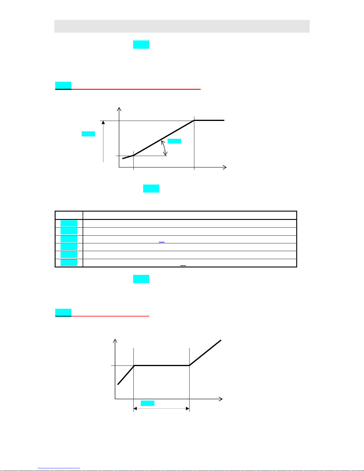
Exmple of setting of process input:
You want to display the input signal 4 to 20 mA in the range 6.0 to 24.0.
Set dEC1 = 0.0, rL1 = 6.0 a rh1 = 24.0. The distribution between values 6.0
and 24.0 will be linear.
11.2 Control, the control output
You can select in the controller ON/OFF(2 state) or PID controlling for heating or cooling. If
PID controlling, you can use autotuning function for finding optimal PID parameters, see
page 26 and the power limit function, see page 47.
Parameters for configuration of the control output are in configuration level, menu out1.
ON / OFF control
ON / OFF control is selected by setting ot1 = ht2 (heating control) or CL2 (cooling
control). It is used for less exacting application. It is not possible to achieve zero hysteresis
value on principle. The process value rises and drops about set point value in the
characteristic way.
Displayed
process
value
input signal 4 mA
20 mA
6.0 24.0
Process
value
time
set poin value
hysteresi
The state of
the control
value
time
ON
OFF
Page 46

Configuration and service part
46
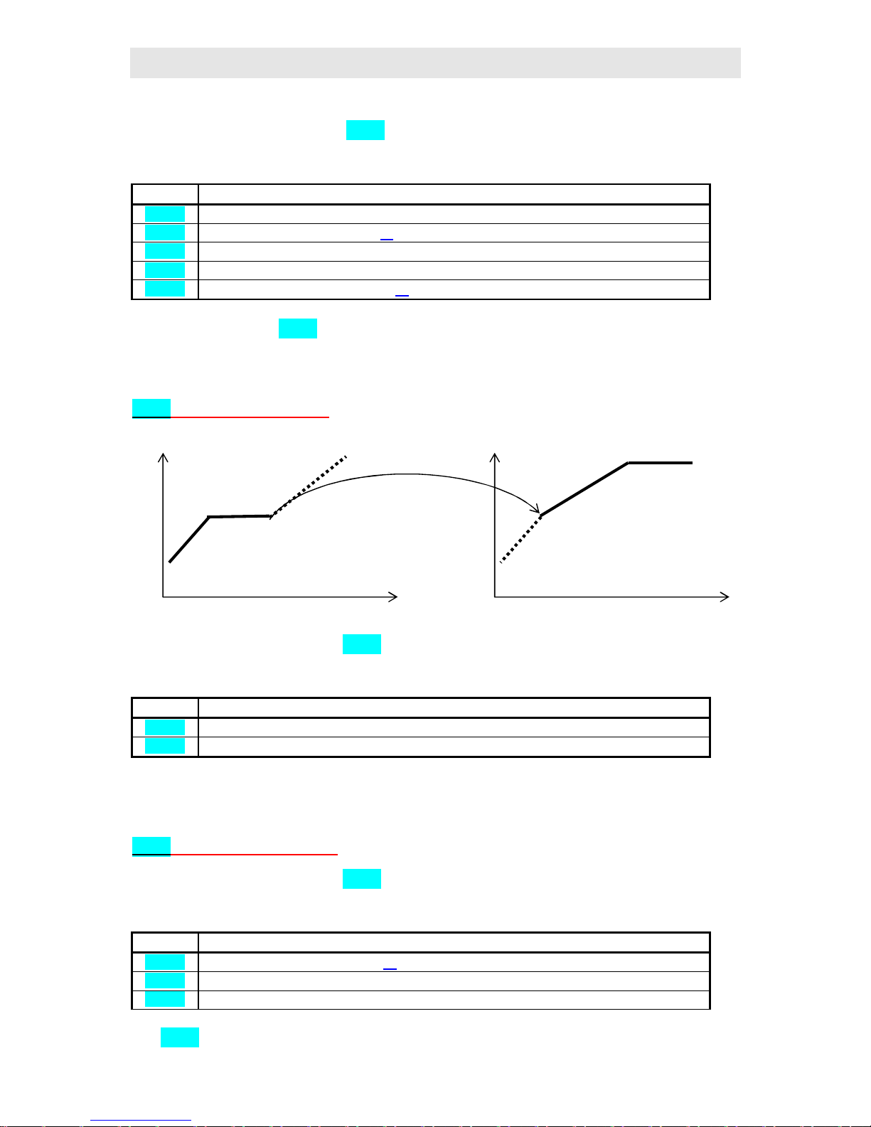
PID control
PID control is selected by setting ot1 = ht (heating) or CL (cooling). It provides the precise
control. For the correct function of the controller, however, it is necessary to set properly PID
parameters. Autotuning for setting of PID parameters is described on page 26.
PID parameters have the following meaning:
• Pb proportional band, is set in measured units. It is the band about the set point value in wich
the controller keeps the temperature.
• It integral factor, in minutes. Integral factor compensates the loss of system. A low integral
value causes a fast integrating factor.
• dE derivative factor, in minutes. Derivative responses to fast changes and tries to react against
them. The more value is, the more derivative factor reacts.
If the control output is 2 state (ON/OFF) (relay or SSR), the power (given in %) transferred to the
output with called pulse width modulation. In each time cycle (parameter Ct1 , that is in operation
level, menu out1) the control output is switched ON once and once OFF. The more power is
neccessary, the wider the width of switching is. The output responses are ilustrated in the third part of
the drawing.
Example of pulse width modulation of the output:
• Time cycle is 10 seconds, the power requested is 30%. The output is ON for 3 seconds and OFF
for 7 seconds.
• Time cycle is 10 seconds, the power requested is 5%. The output is ON for 0,5 seconds
and OFF for 9,5 seconds.
Importand:
• The duration of cycle has the influence on the quality of control. The longer the cycle is ,
the less the quality of control is.
• If the electromechanical unit (relay, switching contactor), is used for the conrol output, the
duration of time cycle must be set longer with regard to lifetime of switch.
Process
value
time set pint value
Power on
the output
time 100 %
The state of
the control
output
time ON OFF Time cycle
Page 47

Configuration and service part
47
11.3 Power limit function
You can improve the quality of control by limiting of the output power.
Limit power can be set in configuraion level (parameters SPL1, PLd1 a Plu1 see page 35)
and in extended configuration menu (parameters SPu1, u1,…, SPu4, u4 see page 41).
Power limiting in configuration menu
With parameters SPL1, PLd1 and Plu1 you can limit output power in two bands. Parameter
PLd1 is setting the maximal power, if the measured value is lower then SPL1. Parameter
Plu1 is setting maximal power if the measured value is higher then SPL1.
Example how to use the power limit function:
When rising at set point value the big overshoot occurs. One of possible solution is the power
limit in the vicinity of set point value. The procedure is the following:
• Find out the power supplied to the stable system.
• Set SPL1 on the value by several °C less then set point value.
• Set power limit PLd1 to 100%.
• Set power limit Plu1 approx. by 10 to 20% higher than the power supplied to the stable
system.
Power limiting in extended configuration menu
In extended configuration level, menu out1 you can limit power with aid the curve, where
is maximal output powerdirect dependent on actual measured value of controlled system. It is
possible to set altogether four decided level(SPu1 to SPu4) and them assign maximal
permitted powers ( u1 to u4).
Process
value
tim
SPL1
Powe
r limit high
PLu1
Pover limit low
PLd1
u1
u4
u3
u2 SPu1 SPu2 SPu3 SPu4
measured
value
Maximal
permitted
Page 48

Configuration and service part
48
Resulting limitation of power
Limiting power by parameters Plu1, SPL1, Pld1 and SPu1, u1,…, SPu4, u4 is
resulting limitation of power always smaller from both settings.
11.4 Alarm, signalling
The second output (output 2) can be used for alarm or signalling.
The parameters for the output configuration are in configuration level, menu out2, you will
find setting of alarm / signal limits o2Lo and o2hI in operation level, menu out2.
Setting of alarm / signal output
Set the function with parameter ot2 :
• ot2 = no, the output is not used.
• ot2 = ALPr, alarm defined by absolute value.
• ot2 = ALdE, alarm defined by the deviation from set point value.
• ot2 = SGPr, signalling defined by absolute value.
• ot2 = SGdE, signalling defined by the deviation from set point value.
Important:
• Relay in standby MODE means active alarm, deactivated signalling.
• When controller is switched OFF, error of sensor, error of controller the alarm is active.
• When controller is OFF, sensor error, error of controller the signalling is deactivated.
Alarm / signalling, absolute value:
process
value
tim
o2Lo o2hI
Active
Active
deactivate
u1
u4 u3
u2 SPu1 SPu2 SPu3 SPu4
measured
Maximal
permitted
Pld1 SPL1 Plu1
Page 49

Configuration and service part
49
Alarm / signalling, the deviation from set point value:
Temporary, permanent (latched) alarm / signalling
Alarm / signalling can be temporary (LAt2 = oFF) or permanent (LAt2 = on).
• Temporary alarm / signalling will turn automatically off when alarm / signal condition is
over.
• Turn OFF permanent (latched) alarm / signalling when the alarm / signal condition is over
by the function o2oF, that is found in operation level, menu glbl, see page 20. This
function can be set also in user menu. Permanent alarm / signalling is also turned off after
supply voltage interruption.
Silencing of alarmu / signalling
Silencing of alarm / signalling can be used to disable alarm / signalling at startup rising to set
point value. This state should not be evaluated as error because the system is not yet stable.
This function is set with parameter SIL2:
• SIL2 = oFF, function is not active
• SIL2 = on, alarm / signalling can be activated after the process value at startup rising
reached the allowed range for the first time (between alarm limits
Active sides of alarm / signalling
With parameter o2Sd you can choose the active side of alarm / signalling:
• o2Sd = LohI, both sides (limits) are active.
• o2Sd = hI, only high alarm / signal side (limit) is active
• o2Sd = Lo, only low alarm / signal side (limit) is active
process
value
tim
o2Lo o2hI
Active
Active
Deactive
Set point value
process
value
tim
Active
Active
Deactive
when startup
alarm/signalling
is deactivated
Page 50

Configuration and service part
50
11.5 Analog (Retransmit) output
Analog (Retransmit) output transmits the value by the analog signal. For analog output it is
neccesary to set quantity to be transmitted, the type of signal for transmitting and scale.
Parameters for configuration of analog output are in configuration level, menu rtMt.
The quantity to be transmitted
• Aout = PrC, transmits process value (upper display). It is used especially for recording
of measured process values on the recorder.
• Aout = StPt, transmits set point value (lower display). The main usage is in system
Master-Slave when controller transmits set point value to other controllers in Slave
MODE.
• Aout = Pcnt, transmits actual power on the control output. It is possible to use this
for the cascade control (the control of systems with high transport delay
Analog signal
Set the output analog signal with parameter Proc:
• Proc = 0-20, output analog signal is 0 to 20mA.
• Proc = 4-20, output analog signal is 4 to 20mA.
Scale
With the parameters rtrL and rtrh you can set the scale for transmitting the process value
or the set point value, with parameters rtPL and rtPh you set scale for transmitting of the
control output.
• The value rtrL, rtPL corresponds to transmitting signal 0 resp. 4mA.
• Hodnotě rtrh, rtPh corresponds to transmitting signal 20mA.
• Distribution is linear.
Important:
• Analog signal of process value is deactivated when there is a error of controller, see page
5 or if input sensor is not selected or broken (on upper display ----).
• Analog signal of set point value is deactivated when there is a error of controller, se page
6 or when the set point value is turned OFF (on lower display oFF).
• Analog signal of actual power of the control output is deactivated when there is a error
of controller, see page 6.
Page 51

Configuration and service part
51
11.6 Output event
For the event output you can set its response to the interruption of programme with the
parameter IEt_:
• hoLd… the event output remains in the unchanged state.
• oFF… the event output is turned OFF.
• on … the event output is turned ON.
11.7 Signalling of the run and the end of a programme
The output 3, 4, 5 can be set for signalling of the run and the end of a programme.
Signalling of the programme run
Set it with parameter ot_ = SGA.
If the programme runs, the output is turned ON. If the programme does not run, the output is
turned OFF.
Signalling of the programme end
Set it with parameter ot_ = SGb.
The end of the programme is indicated by switching ON of the output. The duration of
switching ON can be set by parameter tSG3.
11.8 Lock for menu of editing a programme
When you set parameter ProG = on menu for editing a programme is locked (this menu
can be entered from basic level by long pressing the key . ).
With help of this parameter you can disable any action to editing a programme for a user.
set point
valuetemperatur
čas
Interruption of
programme:
State of events outputs
is set by parameters
IEt_
End of programme:
State of event outputs is
changed by setting in
step End in
programme
Page 52

Configuration and service part
52
11.9 Setting of user menu
User menu, se page 8, provides a user with the simpliest access for viewing and setting
parameters. The list of parameters that will be present in user menu, and their sequence are
optionally set.
You can create user menu in configuration level, menu uSEr, see page 38.
Example how to create user menu:
You want to place on the first (1.) position of user menu parameter Ent1, on 2. position
parameters for viewing a state of running programme run. Proceed as follows:
• Set parameter StP1 = Ent1.
• Set parameter Stp2 = run.
• 3 to 8 positions are not used, set parameters StP3 to StP8 with no.
You will look over the result in user menu.
11.10 How to lock menu and parameters
If your controller is set you can lock:
• The access to configuration level and protect it with password.
• The menu ProF, PCPY, glbl, out1, out2 in operation level
• The setting of set point value SP1 when there is ON/OFF control.
You will find the parameters for locking in configuration level, LoC, see page 39.
Important:
• You can simplify the setting of the controller for user by locking simple items.
• By locking single items you will prevent a user from inappropriate actions to setting of the
controller.
11.11 Monitoring of consumed energy
The controller provides you to monitor the approximate consumed energy:
• Total consumed energy, value in kWh is indicated by the parameter Ptot, that is in
operation level, menu MonI or it can be set accessible in user menu.
• For one firing, value in kWh is indicated by parameter PPGM, that is in operation level,
menu MonI or you can make it accessible in user menu.
Important:
• For the correct counting of consumed energy set in the parameter PoW input power of the
furnace (equipment). You will find the parameter in configuration level, menu SYS, see
page 37.
• The counters of consumed energy Ptot and PPGM have maximum range 9999.After
reaching this the counters resets and counting starts further from 0.
• The counter of consumed energy PPGM is automatically reset at each startup of a
programme.
• The counter Ptot is possible to reset in service level, menu SYS, parameter ClrP, see
page 43.
Page 53

Configuration and service part
53
12 Table of parameters
write down your own complete setting of the controller to the table below.
12.1 Configuration and operation level
Parameters of operation level and set point value SP1 are in menu oPEr
InP1
out1
out2
rtMt
CoM
StPt
In1
ot1
ot2
Aout
bAud
SP1L
dEC1
PLd1
Lat2
ProC
Prot
SP1h
rL1
SPL1
SIL2
rtrL
Addr
SLEP
rh1
PLu1
O2Sd
rtrh
Ftr1
hYS2
rtPL
rtPh
SYS
Prun
oPEr
uSEr
LoC
PoW
GSd
SP1
dE1
StP1
SP1
ALGo
tCon
CAL1
Pb2
StP2
ProF
Pid2
Pout
hPEr
It2
StP3
PCPY
AtSP
Strt
hSto
dE2
StP4
GlbL
Aret
StoP
PPEr
ct1
StP5
Ot1
tdEL
Psto
hYS1
StP6
Ot2
Pb1
o2Lo
StP7
Set
It1
o2hI
StP8
PASS
12.2 Table of programme
You can use the following table for editing your own programmes.
Prog:
StEP tYPE SP tI rt E1 E2 E3 Gd JP JS
1
2
3
4
5
6
7
8
9
10
11
12
13
14
15
Page 54

Configuration and service part
54
13 Technical parameters
The controller is intended for use in industrial or laboratory equipment, the category of
pollution / overvoltage II.
Regulace
• PID, PI, PD, P control, autotuning / automatic setting of PID parameters
• 2-state (ON/OFF) control
• control of heating or cooling
Alarm / signalling
• absolute or relative defined by the set point value
• temporary or permanent alarm / signalling
• silencing of alarm / signalling at startup of the controller
• selection of limits high / low , low, high
Controlling / regulation to set point value
• programme control, 30programmes, 15 steps
• control to the constant set point value
Indicators and keys
• two14 mmLED displays for displaying 4 figures
• three LED diodes (control output indicator, alarm / signal indicator, indicator for the state
of controller)
• four keys, setting is done via menu
Sensors, inputs
Thermocouple input is isolated or non-isolated, the detection of bad-wired / broken sensor:
• no … no input is set
• J … thermocouple J, range -200 to 900°C
• K … thermocouple K, range -200 to 1360°C
• t … thermocouple T, range -200 to 400°C
• n … thermocouple N, range -200 to 1300°C
• E … thermocouple E, range -200 to 700°C
• r … thermocouple R, range 0 to 1760°C
• S … thermocouple S, range 0 to 1760°C
• b … thermocouple B, range 300 to 1820°C
• C … thermocouple C, range 0 to 2320°C
• d … thermocouple D, range 0 to 2320°C
Page 55

Configuration and service part
55
Resistance input Pt100 platinum, (RTD – resistance temperature detector) 2 or 3 wire, DIN
curves, the detection of bad-wired / broken sensor:
• no … no input set
• rtd … sensor Pt100, range -200 to 800°C
Process input, input impedance 5 Ohms for current inputs, 10 kOhms for voltage inputs,
without teh detection of bad-wired / broken sensor:
• no … no input is set
• 0-20 … 0 – 20 mA, range -499 to 2499 units
• 4-20 … 4 – 20 mA, range -499 to 2499 units
• 0-5 … 0 – 5 V, range -499 to 2499 units
• 1-5 … 1 – 5 V, range -499 to 2499 units
• 0-10 … 0 – 10 V, range -499 to 2499 units
Outputs
• open collector / DC driver, 10VDC for switching ON, max. 30 mA
• electromechanical relay, 230VAC/5A or 30VDC/5A, přepínací, bez útlumového členu
(pouze 1. a 2. výstup)
• elektromechanické relé, 230Vstř/2A nebo 30Vss/2A, switching ower, without RC (only
output 3. 4. and 5. )
• DC current 4-20 mA, galvanic isolated, load max. 500 Ohm (only the control output)
• DC voltage 0-5 V, galvanic isolated, load min.1 kOhm (only output 1.)
• DC voltage 0-10 V, galvanic isolated, load min.1 kOhm (only output 1.)
• analog (Retransmit) 0-20 mA, 4-20 mA, load max.100 Ohm (only auxiliary input / output)
• communications RS 232, galvanic isolated (only auxiliary input / output)
• communication EIA 485, galvanic isolated (only auxiliary input / output)
Accuracy of inputs
• ±0,1% of span / range (min. 540ºC) , ±1 digit at 25ºC ±3ºC of ambient temperature ±10%
rated supply voltage
• temperature stability ±0,1ºC/ºC in ambient
• voltage stability ±0,01%/% of change in supply voltage
Accuracy of analog (Retransmit) output
• ±0,1% of range (min. 540ºC) at 25ºC ±3ºC ambient temperature and at ±10% rated supply
voltage
Supply voltage
• 230 VAC +10%/-15%, 50/60 Hz, internal slow fuse 2 A/250 V
• 12 to 16 VDC or VAC, 50/60 Hz, internal slow fuse 2 A/250 V
• input power max. 6 VA
• data stored in memory upon power failure
Page 56

Configuration and service part
56
Operating environment
• 0 to 50 ºC
• 0 to 90 % relative humidity, non-condensating
Shipping and storage
• -20 až 70 ºC
Dimensions
• width x height x lenght, 96 x 96 x 153 mm
• depth behind panel surface 146 mm
• cutout into the panel 90,0
+0,5
x 90,0
+0,5
mm, the thickness of the panel 1,5 až 10 mm
13.1 Warranty
The supplier provides 36-month warranty on defects in material and workmanship on this
controller with exception on defects caused by mechanical or electrical wearing out of the
outputs. This warranty does not also apply to damage resulting from inappropriate
transportation and storage, misue, wrong wiring, ambient influences (especially effects of
electrocal overvoltage, electrical values and temperatures of inadmissible intensity, chemical
materials, mechanical damage) electrical or mechanical overloading of inputs and outputs.
Page 57

Configuration and service part
57
13.2 Description of model
MT825 - a b – c d e f g h – i j k - l
Ø a: modification
A = programme controller
Ø b: vstup
T = thermocouple
R = resistance Pt100
P = process
Ø c: output 1, control
K = ss driver
R = electromechanical relay
P = current 4-20 mA
N = voltage 0-5 V
M = voltage 0-10 V
Ø d: output 2, alarm/signalling
0 = none
R = electromechanical relay
Ø e: output 3, event 1 ***
0 = none
R = electromechanical relay
Ø f: output 4, event 2 ***
0 = none
R = electromechanical relay
Ø g: output 5, event 3 ***
0 = none
R = electromechanical relay
Ø h: control input/output
0 = none
E = analog, retransmit
X = communications RS 232
A = communications EIA 485
Ø i: supply voltage
0 = 230 VAC/50Hz
A = 12 to 16 VDC or VAC
Ø j: data storing
0 = 200 values
2 = 5000 values
Ø k: user configuration
0 = without user configuration
*** … possible configuration is:
1 event output – output 3
2 event output – output 3 and 4
3 event output – output 3, 4 and 5
Page 58

58
14 Index
1 Introduction...........................................................................................................................................3
2 Basic terms.............................................................................................................................................4
2.1 Operation and description of controller................................................................................................4
2.2 Modes of controller.............................................................................................................................5
2.3 Information and error messages...........................................................................................................5
2.4 Overviev of levels, menu....................................................................................................................7
3 User level................................................................................................................................................8
3.1 User menu..........................................................................................................................................8
3.2 Programme menu..............................................................................................................................10
3.3 Starting a programme........................................................................................................................15
3.4 To hold, to contrinue with and to end a programme...........................................................................16
4 Operation level.....................................................................................................................................17
4.1 ProF, creations of programme profiles.........................................................................................18
4.2 PCPY, how to copy programmes...................................................................................................19
4.3 MonI, monitoring of power and consumption...............................................................................20
4.4 CLK, how to set the time clock......................................................................................................20
4.5 glBl, global parameters..............................................................................................................20
4.6 out1, setting parameters of control output...................................................................................21
4.7 out2, alarm set points / signal set points......................................................................................21
5 Tips......................................................................................................................................................22
5.1 Running of programme, options for operation....................................................................................22
5.2 State Hold, Abort..............................................................................................................................22
5.3 Guaranteed Soak Deviation - GSD....................................................................................................22
5.4 Event outputs....................................................................................................................................23
5.5 Fixed programme..............................................................................................................................23
5.6 Interruption of supply voltage............................................................................................................25
5.7 Data history......................................................................................................................................25
5.8 Printing of measurement protocols on the printer...............................................................................26
5.9 Autotuning - automatic setting protocols onthe printer.......................................................................26
5.10 Time-limited work of the controller and its unlocking.......................................................................27
6 Installation...........................................................................................................................................28
7 Power wiring........................................................................................................................................29
8 Putting into operation..........................................................................................................................32
8.1 Guidelines.........................................................................................................................................32
9 Configuration level..............................................................................................................................33
9.1 InP1, setting of input..................................................................................................................34
9.2 out1, control output....................................................................................................................35
9.3 out2, alarm / signal output..........................................................................................................35
9.4 rtMt, analog output.....................................................................................................................36
9.5 CoM, communications...................................................................................................................36
9.6 StPt, features of set point value..................................................................................................36
9.7 SYS, system parameters................................................................................................................37
9.8 Prun, programme parameters......................................................................................................37
9.9 oPEr, setting parameters in operation level..................................................................................38
9.10 uSEr, setting of user menu...........................................................................................................38
9.11 LoC, lock.....................................................................................................................................39
10 Service level.........................................................................................................................................40
10.1 ASEt, extended configuration menu.............................................................................................41
10.2 SYS, system parameters................................................................................................................43
10.3 dIAG, diagnostics of inputs and outputs........................................................................................43
10.4 rSt, editing of initial or user parameters......................................................................................43
11 Tips of configuration...........................................................................................................................44
11.1 Measurement................................................................................................................................44
11.2 Control, the control output............................................................................................................45
Page 59

59
11.3 Power limit function.....................................................................................................................47
11.4 Alarm, signalling..........................................................................................................................48
11.5 Analog (Retransmit) output...........................................................................................................50
11.6 Output event.................................................................................................................................51
11.7 Signalling of the run and the end of a programme..........................................................................51
11.8 Lock for menu of editing a programme.........................................................................................51
11.9 Setting of user menu.....................................................................................................................52
11.10 How to lock menu and parameters................................................................................................52
11.11 Monitoring of consumed energy...................................................................................................52
12 Table of parameters.............................................................................................................................53
12.1 Configuration and operation level.................................................................................................53
12.2 Table of programme.....................................................................................................................53
13 Technical parameters..........................................................................................................................54
13.1 Warranty......................................................................................................................................56
13.2 Description of model....................................................................................................................57
14 Index....................................................................................................................................................58
 Loading...