

Page 1
MIKROTHERM® 825
MT825-A,
Communications
MT825A/C 11/09 Rev.3/Soft.4
THERMOPROZESS s.r.o.
Riegrova 2668/6c
370 01 České Budějovice
tel.: +420 387 313 182
fax : +420 385 340 947
e-mail: info@thermoprozess.cz
internet : www.thermoprozess.cz
THERMOPROZESS
Page 2

Communications
2
1 Scope of communications
Communication line enhances usability of the controller from autonomous controller to the
one which performs the tasks in a system. Basic feasibilities are described in the 5 following
articles:
• Reading data from the controller, Prot = Mod. Enables to acquire data (SP values,
process values, ..) for PC, their visual data processing and storing. The form for showing
and presenting depends on the features of the visual program used.
• Configuration of controller, Prot = Mod. In graphic environment of PC you can
easily configure and set parameters that are transferred to PC by one command. The
configuration via PC can be used for example for more sophisticated setting of controllers
or for setting of production line by the technology procedures stored in PC.
• The controllers configured in system Master – Slave, Prot = SGnL. The controller
MT825A - MASTER retransmits set point value and the SLAVE - controllers (MT600)
receive this value and process it. In comparison with analog retransmit the MASTERSLAVE system has the advantage in galvanic isolation of controllers and the precision of
transferring of STP value in 1 decimal point.
• Cascade controlling, Prot = SGnL. Used in process with long lag times between the
energy source and process measured value.
• Printing protocols of measurement, Prot = Prnt. Time, process and set point values
are shown on a printed copy, the format is illustrated below.
************************
DATE: 20.08.1999
************************
time: sp: c:
15:47 852 850
15:57 860 859
16:07 868 868
16:17 876 877
16:27 884 884
16:37 892 892
16:47 900 901
16:57 900 900
17:07 oFF 889
17:17 oFF 852
Page 3
Communications
3
2 Communication interfaces
The controllers can be equipped with communication interface RS 232 or EIA 485.
The baudrate of the communication is permanently set at 9600 Bd, the data bits is 8,
no parity, 1 stopbit.
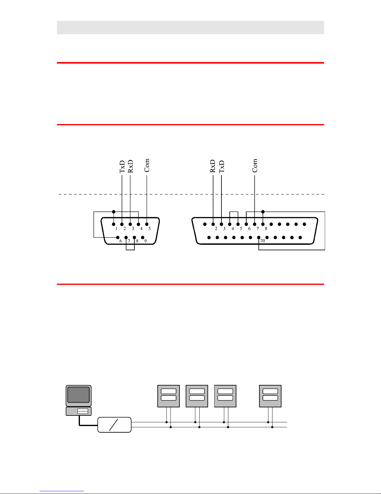
2.1 Interface RS 232
The interface RS 232 is intended for the link of 1 PC with 1 controller. Maximum network
length can be 12 meters. The wiring of standard connectors DB-9 and DB-25 on the side of
PC is illustrated in the following picture.
2.2 Interface EIA 485
The interface EIA 485 is suitable for industrial environment. The local network with this
interface can link as many as 32 controllers with PC up to the distance 1200 meters. When
repeaters are used more controllers can be linked at longer distance. In basic wiring there
must be an appropriate converter or PC card for transferring of interface RS 232 to EIA 485 at
the side of PC.
If controllers work in the environment with low interference, the communication line can be
carried out with twisted pair cable. The simplest wiring of communication line illustrates the
following picture.
RS 232
EIA 485
Side of controller
Side of PC
Page 4

Communications
4
3 Protocol MODBUS
The communication protocol MODBUS is intended for creating networks of type „Master –
Slave“, when „Master“ is PC, „Slave“ are always controllers. Its characteristic is simple, but
reliable structure with these features:
• Defined length of transmitted commands.
• Identification of the terminal equipment with the address (for MT825 address 1 to 250).
• The back confirmation of each command.
• The report is secured with CRC code.
• The transfer of error reports.
3.1 General structure of protocol
Address of
controller
Command
Address of register and/or data CRC
1 byte 1 byte n bytes 2 bytes
The commands for MT825:
• Read – 03H or 04H
• Write to 1 register – 06H
• Back inquiry – 08H
3.2 Operation - read
This operation enables reading as many as 32 registers in a row one after another. If register is
not defined the controller returns the value – 32000, if the register is not active
the controller returns the value –32001.
Command:
Address of
controller
03H Address of 1. read register Number of read registers CRC
1 byte 1 byte
2 bytes (1. byte higher) 2 bytes (1. byte higher) 2 bytes
Response:
Address of
controller
03H Number of
bytes
1. read register … The last read register CRC
1 byte 1 byte 1 byte 2 bytes (1. byte
higher)
2 bytes (1. byte higher) 2 bytes
Example: reading of register 100 (64H, set point value), controller
at the address 12 (0CH)
Command: 0C 03 00 64 00 01 C4 C8
Response: 0C 03 02 01 C8 95 83
Page 5

Communications
5
3.3 Operation - write (06H)
This operation enables writing a value to 1 register of controller:
Command:
Address of
controller
06H Address of register Data CRC
1 byte 1 byte 2 bytes (1. byte higher) 2 bytes (1. byte higher) 2 bytes
Response if the command is performed (is identical with the command):
Address of
controller
06H Address of register Data CRC
1 byte 1 byte 2 bytes (1. byte higher) 2 bytes (1. byte higher) 2 bytes
Example: writing to register 100 (64H, set point value), controller at the address
12 (0CH)
Command: 0C 06 00 64 01 C8 C9 0E
Response: 0C 06 00 64 01 C8 C9 0E
Response, error report:
Address of
controller
Command +
80H
Error reports CRC
1 byte 1 byte 1 byte 2 bytes
Error reports:
• 01 – error of command entered, error in CRC.
• 02 – register does not exist or is intended only for reading.
• 03 – data are beyond the limits.
• 04 – writing to register failed (e.g. error of hardware, too high interference …)
Example: error of the register entered
Command: 0C 01 00 64 04 20 7F D0
Response: 0C 81 01 10 53
Example: error, the register does not exist
Command: 0C 06 00 69 04 20 5B D3
Response: 0C 86 02 52 62
Example: error, data beyond the limits
Command: 0C 06 00 64 4E 20 FD 70
Response: 0C 86 03 93 A2
3.4 Operation - back inquiry:
This operation is only intended for the detection of the controller at the relevant address.
Page 6
Communications
6
Command:
Address of
controller
08H Data CRC
1 byte 1 byte 4 bytes 2 bytes
Response:
Address of
controller
08H Data CRC
1 byte 1 byte 4 bytes 2 bytes
Example: back inquiry, controller at the address 12 (0CH)
Command: 0C 08 0A 14 1E 28 AB 74
Response: 0C 08 0A 14 1E 28 AB 74
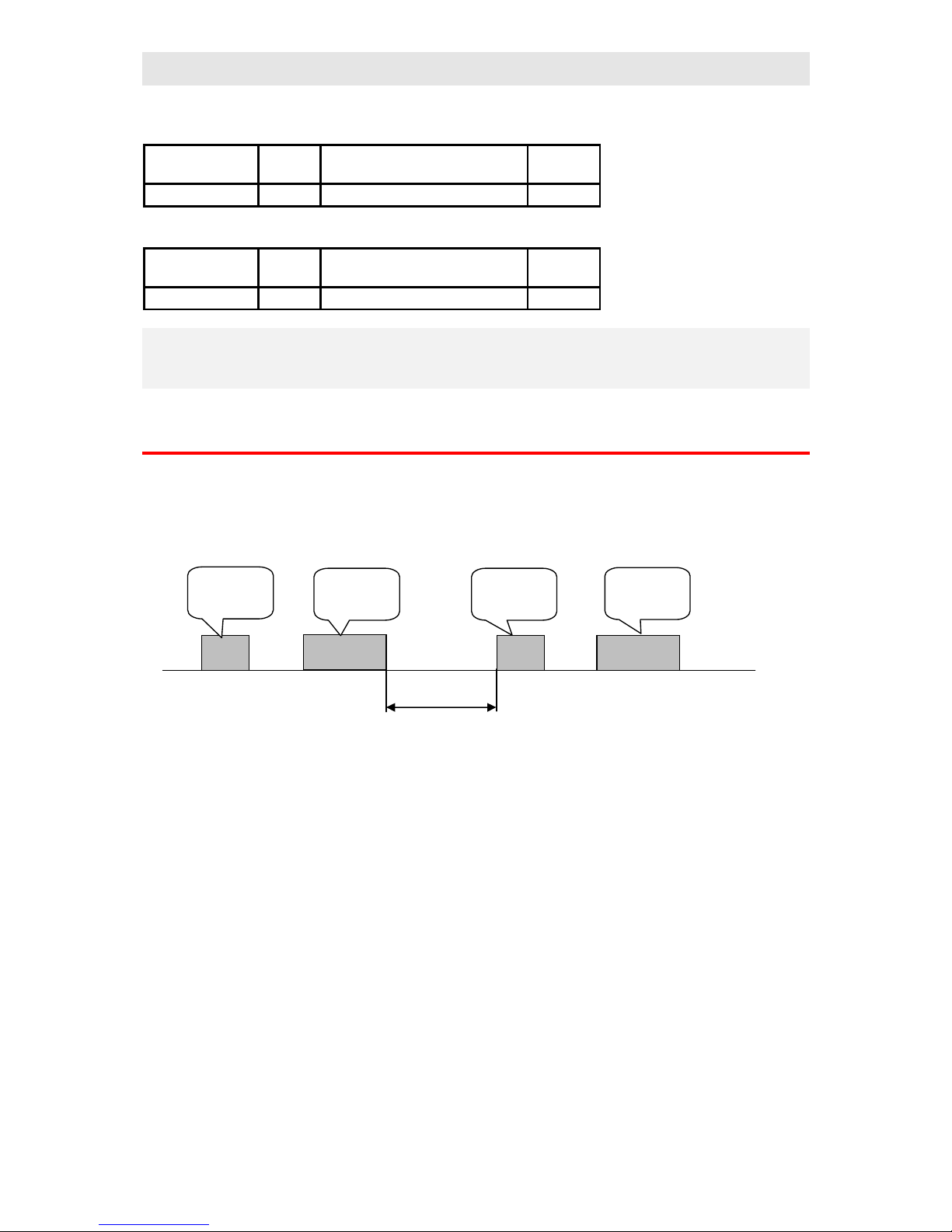
3.5 Timing of communication line
If there is more than 1 controller on the line (only line EIA 485) it is necessary to observe the
timing shown in the following picture.
The time interval (pause between ending of receiving and transmitting of another command)
must be more or equal to 50ms. In opposite case the data collision might appear.
time
Transmitting
command
Receiving
response
Transmitting of
another
command
Receiving
response
Interval >= 50 ms
Page 7

Communications
7
4 Overview of registers
The table comprises the total overview of registers that are accessible for communication line.
The meaning of particular parameters is the following:
• Display … if you set the relevant parameter via keyboard, on lower display appears
writing stated in the column display.
• Address … address of register. The access for register is shown after the address,
r … read only, r/w … read as well as write.
• Range … range of register values.
• Initiation … initial value at first power-up or after restart.
• Decimal point … determines the number of decimal points that are to be displayed.
The conversion shows the following table.
Decimal point Value entered with
communication line
Display reading Note
0 1800 Factory setting, no decimal point
1 180.0 Factory setting, 1 decimal point
2 18.00 Factory setting, 2 decimal point
dEC1 (0) 180 By par. dEC1 (no dec. point), input tc, rtd
dEC1 (1) 1800 180.0 By par. dEC1 (1 dec. point), input tc, rtd
dEC1 (0) 180 By par. dEC1 (no dec. point), input process
dEC1 (1) 18.0 By par. dEC1 (1 dec. point), input process
dEC1 (2) 1.80 By par. dEC1 (2 dec. points), input process
dEC1 (3) 0.180 By par. dEC1 (3 dec. points), input process
• Note … the meaning of register is mostly stated
System registers
Display Address Range Initiation Dec. point
Note
SoFt
0 r Software version
1 r 0 … 2kB
1 … 32kB
Embedded memory RAM for
datalogger
2 r 0 … tc
1 … rtd
2 … proc
Measuring input
3 r 0 … none
1 … retransmit
2 … communication
Control input, output
4 r 0 … SSD
1 … relay
2 … process
Control output
5 r 0 … none
1 … relay
Alarm / signal output
6 r 0 … none
1 … 1 relay
2 … 2 relay
3 … 3 relay
Event output
Page 8

Communications
8
Display Address Range Initiation Dec. point
Note
Aut
12 r/w 0 … oFF
1 … on
0 Start on, stop oFF
automatic setting of PID
parameters
50 r Process value
upper display
dEC1
If sensor is not set, the controller
returns the value –22000.
If the bad sensor is detected
the controller returns the value –
22001.
51 r Ambient temperature 1 The controller returns only
process/measured value for
thermocouple input
60 r Actual set point value
lower display
dEC1
If SP value is OFF oFF,
the controller returns the value -
22000
70 r PID controlling:
0 to 1000
ON/OFF controlling:
0 … switched OFF
1 … switched ON
1
Control output.
Power at % for PID controlling
State of the output for ON/OFF
controlling
71 r 0 … switched OFF
1 … switched ON
Alarm/ signal output
72 r 0 … switched OFF
1 … switched ON
Event output 1
73 r 0 … switched OFF
1 … switched ON
Event output 2
74 r 0 … switched OFF
1 … switched ON
Event output 3
80 r 0 to 9999 0 Total time of the control output
in hours.
81 r 0 to 9999 0 Total consumption of energy
in kWh. After reaching 9999 the
counter is reset and starts from 0.
82 r 0 to 9999 0 Total consumption in kWh for 1
firing. When program is released
the counter is reset and counting
of the consumption starts from 0.
Page 9

Communications
9
Operation level
Display Address Range Initiation Dec. point
Note
100 r/w SP1L to SP1h Set point value, reading appears
on lower display
Pb1
110 r/w 10 to 24990 200
dEC1
Proportional band
It1
111 r/w 0 to 999
0 … oFF
100 1 Integrative value
dE1
112 r/w 0 to 999
0 … oFF
24 2 Derivative value
Pb2
113 r/w 10 to 24990 200
dEC1
Proportional band
It2
114 r/w 0 to 999
0 … oFF
100 1 Integrative value
dE2
115 r/w 0 to 999
0 … oFF
24 2 Derivative value
Ct1
116 r/w 1 to 250 for ot1 =
ht, Cl
5 to 250 for ot1 =
ht2, Cl2
1
15
0 Time cycle
hYS1
117 r/w 10 to 2490 20
dEC1
Hysteresis for switching
ON/OFF of the control output
CAL1
120 r/w -9990 to 9990 0
dEC1
Calibration of measuring input
o2Lo
130 r/w -4990 to o2hI for ALPr,
SGPr
-9990 to 0 pro AldE,
SGdE
-4990
-990
dEC1
Low alarm / signal set points
o2hI
131 r/w o2Lo to 24990 pro
AlPr, SGPr
0 to 9990 pro AldE,
SGdE
24990
990
dEC1
High alarm / signal set points
hPEr
140 r/w 1 … 120 10 0 Period of data storing in minutes
hSto
141 r/w 0 … oFF
1 … ProG
2 … AlSG
3 … Cont
1 Condition for data storing
PPEr
142 r/w 1 to 120 10 0 Period for printing protocol on
the printer in minutes
PSto
143 r/w 0 … oFF
1 … ProG
2 … AlSG
3 … Cont
1 Condition for printing
Page 10

Communications
10
Configuration level
Display Address Range Initiation Dec. point
Note
In1
200 r/w Thermocouple input:
0 … no
1 … J
2 … K
3 … t
4 … n
5 … E
6 … r
7 … S
8 … b
9 … C
10 … d
RTD input:
0 … no
1 … rtd
Process input:
0 … no
1 … 0-20
2 … 4-20
3 … 0-5
4 … 1-5
5 … 0-10
0 Setting of the input sensor
dEC1
201 r/w tc and rtd input:
0 … 0
1 … 0.0
Process input
0 … 0
1 … 0.0
2 … 0.00
rL1
202 r/w -4990 to rh1 -4990
dEC1
Low range of process input
rh1
203 r/w RL1 to 24990 24990
dEC1
High range of process input
Ftr1
204 r/w 0 to 600
0 … oFF
10 1 Input filter
ot1
210 r/w 0 … ht
1 … CL
2 … ht2
3 … CL2
0 for SSD
and proc
2 pro relay
Setting of the control output
PLd1
211 r/w 0 to 100 100 0 Output power limit below SPL1
SPL1
212 r/w -4990 to 24990 250
dEC1
SP value for power limit function
PLu1
213 r/w 0 to 100 100 0 Output power limit above SPL1
Page 11

Communications
11
Display Address Range Initiation Dec. point
Note
ot2
220 r/w 0 … no
1 … ALPr
2 … AldE
3 … SGPr
4 … SGdE
0 Setting of alarm / signal output
Lat2
221 r/w 0 … oFF
1 … on
0 Latching of alarm / signaling
SIL2
222 r/w 0 … oFF
1 … on
0 Silencing of alarm / signaling
o2Sd
223 r/w 0 … LohI
1 … hI
2 … Lo
0 Active limits for alarm /
signaling
hYS2
224 r/w 10 to 2490 20
dEC1
Hysteresis of switching for alarm
/ signal output
SP1L
240 r/w -4990 to SP1h 0
dEC1
The limit of low range for SP
SP1h
241 r/w SP1L to 24990 1000
dEC1
The limit of high range for SP
SLEP
242 r/w 0 … oFF
1 … SP
0 The state of the controller,
if the program does not run
GSD
250 r/w 10 to 9990 100
dEC1
Guaranteed soak deviation
tCon
251 r/w 0 to 999
0 … oFF
0 0 Maximum duration of the
interruption in minutes for
continuing in program
Pout
252 r/w 0 … Cont
1 … hoLd
2 … Abrt
0 Response to the supply voltage
interruption. It takes effect after
the duration Tcon elapsed.
Strt
253 r/w 0 … ProG
1 … PrSt
0 Setting of options
for starting a program
StoP
254 r/w 0 … C E
1 … Ch E
2 … C AE
3 … ChAE
Setting of options for ending up
or interrupting a program
tdEL
255 r/w 1 to 99 10 Time delay for automatic start-up
of program in minutes
PoW
260 r/w 0 to 9990 0 1 Power of system in kWh
ALGo
261 r/w 0 … PID
1 … PID2
0 Alghoritmus of PID controlling
PID2
262 r/w -4990 to 24990 250
dEC1
The limit between PID1 and
PID2
AtSP
263 r/w 0 to 100 75 0 Helping auto/tune set point value
for autotunning in %
ArEt
264 r/w 0 … oFF
1 … on
1 Automatic return from open
menu
Page 12

Communications
12
Display Address Range Initiation Dec. point
Note
StP1
270 r/w 0 … no
1 … hISt
2 … run
3 … CLK
4 … PCnt
5 … Ptot
6 … PPGM
7 … o2oF
8 … Ent1
9 … Ent2
10 … Ent3
11 … Aut
12 … CAL1
13 … hPEr
14 … hSto
15 … PPEr
16 … PSto
1 1st position of user menu
StP2
271 r/w The same as StP1 2 2nd position of user menu
StP3
272 r/w The same as StP1 0 3rd position of user menu
StP4
273 r/w The same as StP1 0 4th position of user menu
StP5
274 r/w The same as StP1 0 5th position of user menu
StP6
275 r/w The same as StP1 0 6th position of user menu
StP7
276 r/w The same as StP1 0 7th position of user menu
StP8
277 r/w The same as StP1 0 8th position of user menu
SP1
280 r/w 0 … oFF
1 … on
0 The lock for set point value SP1
ProF
281 r/w 0 … oFF
1 … on
0 The lock for menu ProF in
operation level
PCPY
282 r/w 0 … oFF
1 … on
0 The lock for menu PCPY in
operation level
GLbL
283 r/w 0 … oFF
1 … on
0 The lock for menu GLbL in
operation level
out1
284 r/w 0 … oFF
1 … on
0 The lock for menu ot1 in
operation level
out2
285 r/w 0 … oFF
1 … on
0 The lock for menu ot2 in
operation level
Set
286 r/w 0 … oFF
1 … on
0 The lock for configuration level
PASS
287 r/w 0 to 9999 1000 0 The password for the entry to
configuration level
Page 13

Communications
13
Extended configuration menu
Display Address Range Initiation Dec. point
Note
ot3
300 r/w 0 … Ent1
1 … ALPr
2 … SGPr
3 … SGA
4 … SGb
0 Setting of the function for
the output 3
IEt1
301 r/w 0 … hold
1 … oFF
2 … on
0 State of the event output 1 when
a program is interrupted
o3hI
302 r/w -4990 to 24990 24990
dEC1
High limit for alarm / signaling
tSG3
303 r/w 1 to 200 10 0 Setting of time of signaling at
the end of program
ot4
310 r/w 0 … Ent2
1 … ALPr
2 … SGPr
3 … SGA
4 … SGb
0 Setting of the function for
the output 4
IEt2
311 r/w 0 … hold
1 … oFF
2 … on
0 State of the event output 2
when a program is interrupted
o4hI
312 r/w -4990 to 24990 24990
dEC1
High limit for alarm / signaling
tSG4
313 r/w 1 to 200 10 0 Setting of time of signaling at
the end of program
ot5
320 r/w 0 … Ent3
1 … ALPr
2 … SGPr
3 … SGA
4 … SGb
0 Setting of the function for
the output 5
IEt3
321 r/w 0 … hold
1 … oFF
2 … on
0 State of the event output 3
when a program is interrupted
o5hI
322 r/w -4990 to 24990 24990
dEC1
High limit for alarm / signaling
tSG5
323 r/w 1 to 200 10 0 Setting of time of signaling at
the end of program
dt
330 r/w 10 to 1000 23 1 Character of derivative factor
ProG
340 r/w 0 … oFF
1 … on
0 The lock for editing a program
Page 14

Communications
14
Editing a program
Display Address Range Initiation Dec. point
Note
Prog
1400 r/w 1 to 30 1 0 Program for editing
StEP
1401 r/w 1 to 15 1 0 Step to be edited
tyPE
1410 r/w 0 … End
1 … StPt
2 … rAtE
3 … SoAK
4 … JuMP
0 Type of step
SP
1411 r/w -4990 to 24990 250
dEC1
Set point value
tI
1412 r/w 0 to 5999 10 0 Time of step in minutes
rt
1413 r/w 10 to 30000 1000
dEC1
Ramp rate up/down in K/hour
JP
1414 r/w 1 to 34 1 0 Jump, number of program
JS
1415 r/w 1 to 15 1 0 Jump, number of step
E1
1416 r/w 0 … oFF
1 … on
0 The event output 1
E2
1417 r/w 0 … oFF
1 … on
0 The event output 2
E3
1418 r/w 0 … oFF
1 … on
0 The event output 3
Gd
1419 r/w 0 … oFF
1 … on
2 … Strt
1 Guaranteed soak deviation
If the parameters of the same program and step are edited currently from the keyboard as well
as from communication line, the values transferred from communication are not accepted.
Starting, holding, interrupting a program
Display Address Range Initiation Dec. point
Note
ProG
1200 r/w 1 to 34 1 0 Program you wish
StEP
1201 r/w 1 to 15 1 0 Step you wish
1210 r/w 0 … no action
1 … start of program
0 Executive command. Program
and step are defined at the
address 1200 and 1201
End
1211 r/w 0 … no action
1 … interruption of
program
0 Executive command
hoLd
1212 r/w 0 … no action
1 … state - hold
0 Executive command
Abrt
1213 r/w 0 … no action
1 … state - abort
0 Executive command
Cont
1214 r/w 0 … no action
1 … program continues
0 Executive command
Page 15

Communications
15
Starting a program by the internal clock
Display Address Range Initiation Dec. point
Note
PCLK
1220 r/w 0 to 34
0 … oFF
0 0 Set number of program you wish
to start up
SCLK
1221 r/w 1 to 15 1 0 Set step from which you like to
start
Mon
1222 r/w 0 to 12
0 … oFF
0 0 Month
dAY
1223 r/w 1 to 31 1 0 Day
hour
1224 r/w 0 to 23 0 0 Hour
Min
1225 r/w 0 to 59 0 0 Minute
Editing of the state of the controller
Display Address Range Initiation Dec. point
Note
1250 r 0 … the program
does not run
1 … program runs
2 … state - hold
3 … state - abort
State of the controller
ProG
1251 r 1 to 34 Actual program that runs
StEP
1252 r 1 to 15 Actual step that runs
EnSP
1253 r Final set point value
trEM
1254 r Time to the end of step, hours
trEM
1255 r Time to the end of step, minutes
How to set the time clock
Display Address Range Initiation Dec. point
Note
YEAr
500 r/w 0 to 99 0 0 Year
Mon
501 r/w 1 to 12 1 0 Month
DAY
502 r/w 1 to 31 1 0 Day
hour
503 r/w 0 to 23 0 0 Hour
MIn
504 r/w 0 to 59 0 0 Minute
Page 16

Communications
16
Reading of measured values, deleting memory
Display Address Range Initiation Dec. point
Note
1300 r/w 0 to 199 pro RAM 2kB
0 to 4999 pro RAM 32kB
0 0 Setting of position for reading
data. 0 sets the newest value,
199/4999 sets the oldest one
1301 r
dEC1
Process value at the position
defined by the address 1300.
If sensor is not set, controller
returns the value –22000. If there
is a error in sensor, controller
returns the value –22001.
1302 r 1 to 12 0 Month, position at the address
1300
1303 r 1 to 31 0 Day, position at the address 1300
1304 r 0 to 23 0 Hour, position at the address
1300
1305 r 0 to 59 0 Minute, position at the address
1300
1330 r/w 0 … no action
1 … deleting of memory
0 Deleting data in the memory of
the controller
Page 17

Communications
17
5 Index
1 Scope of communications........................................................................................................................2
2 Communication interfaces.......................................................................................................................3
2.1 Interface RS 232.............................................................................................................................3
2.2 Interface EIA 485...........................................................................................................................3
3 Protocol MODBUS.................................................................................................................................4
3.1 General structure of protocol...........................................................................................................4
3.2 Operation - reading.........................................................................................................................4
3.3 Operation - writing (06H)...............................................................................................................5
3.4 Operation - back inquiry:................................................................................................................5
3.5 Timing of communication line........................................................................................................6
4 Overview of registers...............................................................................................................................7
System registers.......................................................................................................................................7
Operation level........................................................................................................................................9
Configuration level................................................................................................................................10
Extended configuration menu................................................................................................................13
Editing a program..................................................................................................................................14
Starting, holding, interrupting a program................................................................................................14
Starting a program by the internal clock.................................................................................................15
Editing of the state of the controller.......................................................................................................15
How to set the time clock.......................................................................................................................15
Reading of measured values, deleting memory.......................................................................................16
5 Index.....................................................................................................................................................17
 Loading...