

Page 1
TABULAR DATA SHEET
MAC-220
ECN 5287-MA 121005
Outdoor Split System Heat Pump 1.5 Thru 5 Tons
MODELS: THJD18* THRU 60
13 SEER – R-410A, 1 PHASE
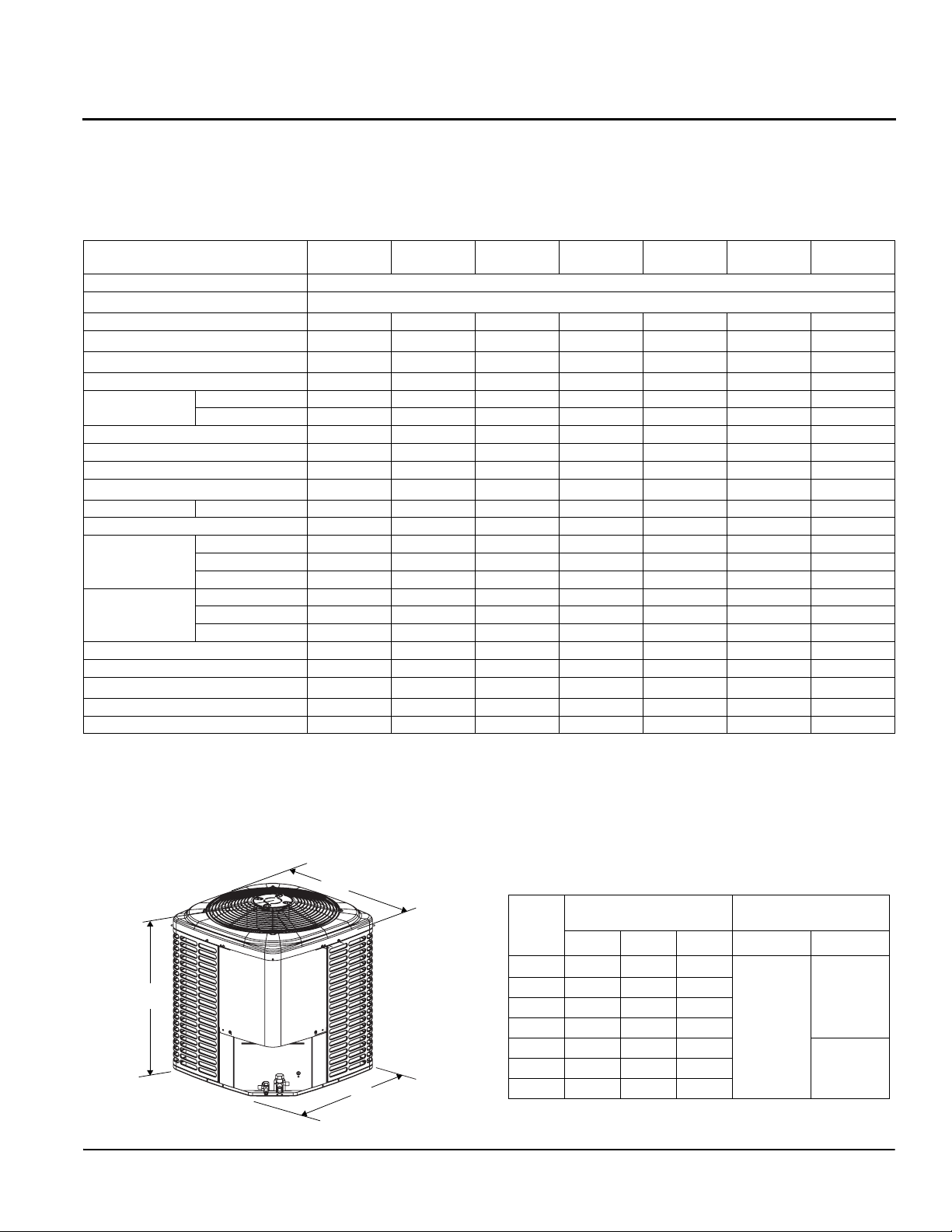
Physical and Electrical Data
MODEL
Unit Supply Voltage 208-230V, 1 60Hz
Normal Voltage Range
Minimum Circuit Ampacity 11.9 11.2 14.1 19.7 20.9 25.6 34.9
Max. Overcurrent Device Amps
Min. Overcurrent Device Amps
Compressor Type Scroll Recip Recip Recip Recip Recip Scroll
Compressor
Amps
Crankcase Heater No Yes Yes Yes Yes Yes No
Factory External Discharge Muffler Yes No No No No No Yes
Factory External Check Valve NoNoNoNoNoNoNo
HS Kit Required with TXV
Fan Motor Amps Rated Load 0.70 0.80 0.80 1.3 1.3 1.3 1.3
Fan Diameter Inches 24 24 24 24 24 24 24
Fan Motor
Coil
Liquid Line Set OD (Field Installed) 3/8 3/8 3/8 3/8 3/8 3/8 3/8
Vapor Line Set OD (Field Installed) 3/4 3/4 3/4 3/4 7/8 7/8 7/8
Unit Charge (Lbs. - Oz.)
Charge Per Foot, Oz. 0.62 0.62 0.62 0.62 0.67 0.67 0.67
Operating Weight Lbs. 172 194 206 218 218 285 284
* These models are shipped with a Hard Start Kit installed at the factory.
1. Rated in accordance with ANSI/AHRI Standard 110-2002, utilization range “A”.
2. Dual element fuses or HACR circuit breaker. Maximum allowable overcurrent protection.
3. Dual element fuses or HACR circuit breaker. Minimum recommended overcurrent protection.
4. See Hard Start Kit Accessory Installation Manual for Hard Start Kit part number for each model.
5. The Unit Charge is correct for the outdoor unit, matched indoor coil, and 15 feet of refrigerant tubing. For tubing lengths other than 15 feet, add
or subtract the amount of refrigerant, using the difference in length multiplied by the per foot value.
A
1
2
3
Rated Load 9.0 8.3 10.6 14.7 15.7 19.4 26.9
Locked Rotor 48.0 43.0 54.0 74.0 88.0 88.0 135.0
4
Rated HP 1/10 1/8 1/8 1/4 1/4 1/4 1/4
Nominal RPM 825 1075 1075 850 850 850 850
Nominal CFM 2000 2900 3000 3800 3800 3600 3600
Face Area Sq. Ft. 15.7 18.3 21.0 23.6 23.6 23.6 23.6
Rows Deep 1 1 1 1 1 2 2
Fin / Inches 22 22 22 22 22 18 18
5
THJD18
S41S3
20 15 20 30 35 45 60
15 15 15 20 25 30 35
No Ye s Yes Ye s Ye s Ye s* N o
6 - 6 9 - 6 9 - 0 10 - 0 9 - 10 14 - 12 13 - 13
C
B
THJD24
S41S4
THJD30
S41S4
All dimensions are in inches. They are subject to change without notice.
Certified dimensions will be provided upon request.
Unit
Model
18 28
24 32 34 34
30 36 34 34
36 40 34 34
42 40 34 34
60 40 34 34
1. Including Fan Guard.
THJD36
S41S4
187 to 252
Dimensions
1
A
THJD42
S41S4
(Inches)
B C Liquid Vapor
34 34
THJD48
S41S4
Refrigerant Connection
Service Valve Size
3/8”
THJD60
S41S4
3/4”
7/8”48 40 34 34
Thermo Products, LLC
Page 2
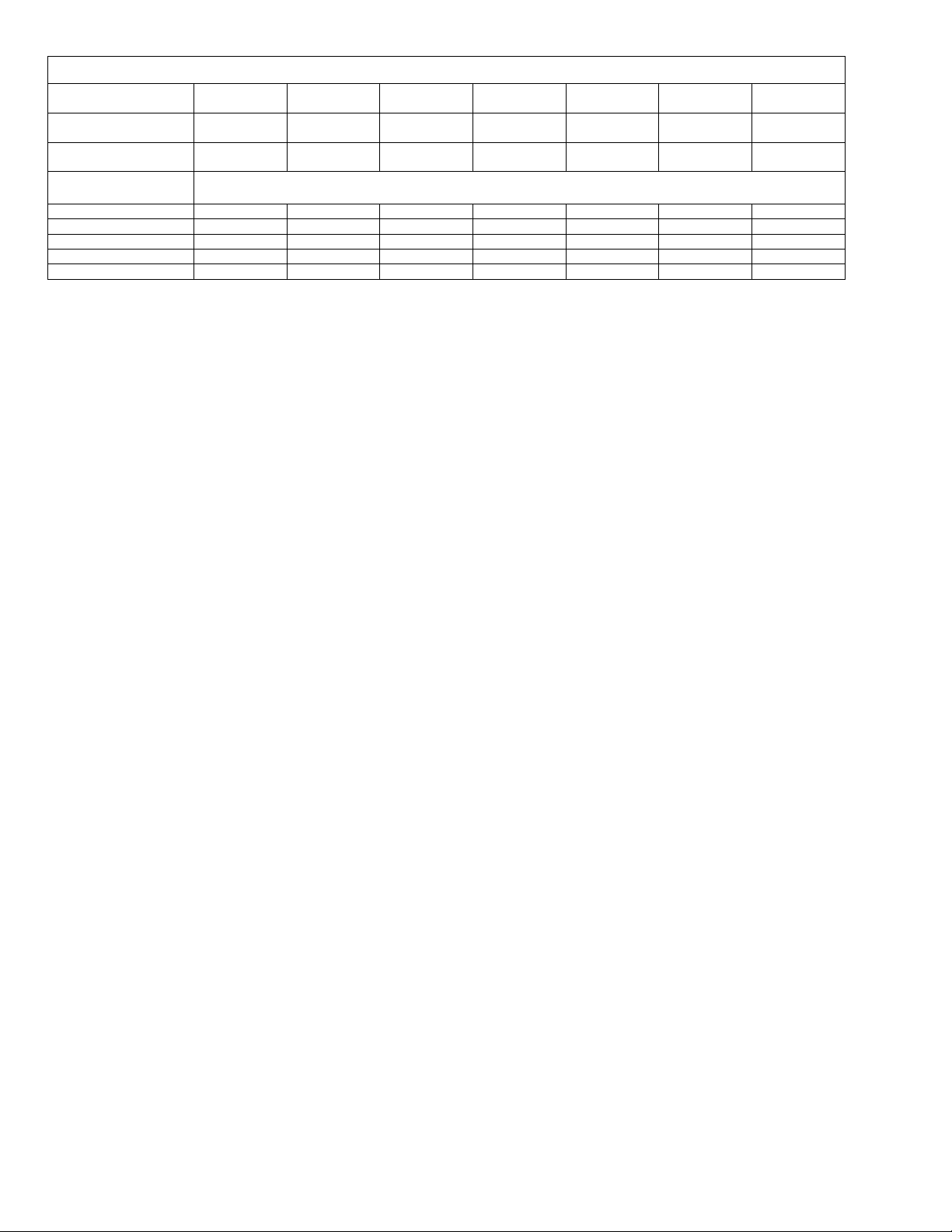
System Charge for Various Matched Systems
Thermo Products, LLC
5235 West State Road 10
North Judson, IN 46366
www.thermopride.com
Copyright © 2012 by Johnson Controls, Inc. All rights reserved.
Outdoor Unit
Required Orifice or
1
TXV
Factory Charge,
lbs-oz
Indoor Unit
2,3
Additional Charge, oz
THJD18
S41S3
.051/4F1 .054/4G1 .063/4G1 .071/4H1 .075/4H1 4J1 4K1
6 – 6 9 – 6 9 – 0 10 – 0 9 – 10 14 – 2 13 - 13
THJD24
S41S4
THJD30
S41S4
THJD36
S41S4
THJD42
S41S4
THJD48
S41S4
THJD60
S41S4
FC/MC/PC/UC18 .051/TXV+0 -- -- -- -- -- -FC/MC/PC/UC35 -- .059/TXV+0 .063/TXV+0 -- -- -- -FC/MC/PC/UC43 -- .059/TXV+23 .063/TXV+25 .071/TXV+6 -- -- -FC/MC/PC/UC60 -- -- -- -- .075/TXV+0 TXV_0 -FC/PC/62 -- -- -- -- -- TXV+25 TXV+0
Footnotes:
1. For applications requiring a TXV use S1-1TVM*** series kit.
2. Systems matched with furnaces or air handlers not equipped with blower-off delays may require blower Time Delay Kit S1-2FD06700224.
3. PC coils cannot be used in downflow or horizontal applications. FC coils cannot be sued in horizontal applications.
Procedures:
1. Unit factory charge listed on the unit nameplate includes refrigerant for the outdoor unit, the smallest matched indoor unit, and 15 feet of
interconnecting line tubing.
2. Verify the TXV or orifice and additional charge required for specific matched indoor unit in the system using the above table.
3. Add additional charge for the amount of interconnecting line tubing greater than 15 feet at the rate specified in Physical and Electrical Data
table.
4. For indoor matches requiring additional charge, the refrigerant needs to be weighed in for specific matched indoor unit and line set lengths.
5. Permanently mark the unit nameplate with the total system charge. Total system charge = base charge as shipped plus charge adder for
matched indoor unit and charge adder for line set.
 Loading...