

Page 1
OIL FIRED FURNACE
INSTALLATION AND OPERATION MANUAL
WITH USERS INFORMATION SECTION
MODEL:
OHCFA072DV4R
WARNING: IF THE INFORMATION IN THESE INSTRUCTIONS IS NOT FOLLOWED EXACTLY, A
FIRE OR EXPLOSION MAY RESULT CAUSING PROPERTY DAMAGE, PERSONAL INJURY, OR
LOSS OF LIFE.
DO NOT STORE OR USE GASOLINE OR OTHER FLAMMABLE VAPORS AND LIQUIDS IN THE
VICINITY OF THIS OR ANY OTHER APPLIANCE.
WARNING: IMPROPER INSTALLATION, ADJUSTMENT, ALTERATION, SERVICE, OR
MAINTENANCE CAN CAUSE INJURY OR PROPERTY DAMAGE. REFER TO THIS MANUAL. FOR
ASSISTANCE OR ADDITIONAL INFORMATION CONSULT A QUALIFIED INSTALLER, OR SERVICE
AGENCY.
PLEASE READ THESE INSTRUCTIONS PRIOR TO INSTALLATION, INITI AL FIRING, AND BEFORE
PERFORMING ANY SERVICE OR MAINTENANCE. THESE INSTRUCTIONS MUST BE LEFT WITH
THE USER AND SHOULD BE RETAINED FOR FUTURE REFERENCE BY QUALIFIED SERVICE
PERSONNEL.
THERMO PRODUCTS, LLC.
PO BOX 217
NORTH JUDSON, IN 46366
PHONE: (574) 896-2133
MO-490
ECN 5095-PC 131030 Made IN USA
Page 2

i
CONTENTS
SECTION PAGE
I. SAFETY SECTION 1
A. CODES AND CLEARANCES 3
II. GENERAL INSTRUCTIONS 5
A. VENTING 5
B. INSTALLATION OF VENTOR 7
C. CONDENSATE DRAIN LINE CONNECTION 10
D. DUCT WORK/AIR CONDITIONING 11
E. AIR FILTER MOUNTED EXTERNAL TO FURNACE 12
F. LIMIT POSITION AND LOCATION 14
G. BURNER INSTALLATION 14
H. BURNER SPECIFICATIONS AND APPLICATIONS 14
I. OILTANK AND PIPING 15
J. ELECTRICAL WIRIING 17
L. BLOWER MOTOR SPEED SELECTION 19
M. BLOWER CONTROLLER INFORMATION FOR ECM MOTOR 21
N. STARTUP PROCEDURES 25
III. USERS INFORMATION SECTION 31
A. OIL SUPPLY 31
B. INSPECTION AREAS 31
C. STARTING THE BURNER 31
D. FILTER CLEANING AND LOCATION 31
IV. INSTALLER'S INSTRUCTIONS TO USER 32
V. DEALER MAINTENANCE 33
A. GENERAL INSPEC TION 33
B. HEAT EXCHANGER CLEANING INSTRUCTIONS 34
D. ELECTRICAL S YST EM 37
E. SUPPLY/RETURN AIR BLOWER 37
F. SUPPLY/RETURN AIR FILTER 37
G. EXTENDED APP L IAN C E SHU T D OWN 38
VI. HOMEOWNER/USER INFORMATION AND ROUTINE MAINTENANCE 40
VII. TROUBLESHOOTING 42
VIII. SEQUENCE OF OPERATIONS FLOW CHART 43
IX. TROUBLE SHOOTING FLOW CHART 45
APPENDIX – A
REPLACEMENT PARTS LIST 49
APPENDIX – B
WIRING DIAGRAMS 52
Page 3

Model Number Digit
1 2 3 4 5 6 7 8 9
10
11
12
Fuel
Configuration
Heat Exchanger
Identifier
Flue
Feature
Capacity
Capacity
Capacity
Blower Type
Clg Airflow Cap.
Clg Airflow Cap.
Burner
Oil Furnace Model Nomenclature Example Model Numbers
O H C F A 0 7 2 D V 4
R
O = Oil
O
H = Highboy D = Downflow
H
C = Heat Exchanger Identifier
C
F = Front
F
R = Rear
A = Single Stage
A
Heating Capacity MBTUH (000's) with factory installed nozzle
0 7 2
D = Direct Drive
D
Clg. Airflow: Example = 48MBTUH = 4 tons @ 400cfm/ton
4 8
Clg. Airflow Variable Speed (ECM) V4 = 4tons
V 4
R = Riello
R
ii
Page 4

1
I. SAFETY SECTION
This page and the following contains various warnings and cautions found
throughout the Oil Furnace Manual. Please read and comply with the statements
below.
WARNING AND CAUTIONS:
WARNING: This furnace is not to be used as a construction heater. See Page 3
WARNING: The predetermined limit locations on all of the Thermo Pride oil fired
furnaces have been tested and approved by Thermo Products, LLC. Any attempt to
relocate these safety controls or replace these safety controls with a control that is not
approved, or is incompatible, may result in personal injury, substantial property damage
or death. See Page 14
WARNING: THE HEAT EXCHANGER MUST BE CLE ANED BY A QUALIFIED
SERVICE PERSON. See Page 34
CAUTION: DO NOT ATTEMPT TO MAKE REPAIRS YOURSELF! See Page 31
WARNING: The area around the furnace should be kept free and clear of
combustible liquids and material, especially papers and rags. See Page 31
WARNING: NEVER burn garbage or refuse in your furnace. Never try to ignite
oil by tossing burning papers or other material into your furnace. See Page 31
WARNING: Thermo Products oil furnaces are designed to burn No. 1 or No. 2
distillate fuel oil. NEVER USE GASOLINE OR A MIXTURE OF OIL AND GASOLINE.
See Page 31
CAUTION: DO NOT ATTEMPT TO START THE BURNER WHEN:
1. Excess oil has accumulated,
2. The furnace is full of vapors
3. The combustion chamber is very hot.
IF ONE OR MORE OF THESE CONDITIONS EXIST, CONTACT A QUALIFIED
SERVICE PERSON. See Page 31
WARNING: DO NOT START BURNER UNLESS BLOWER DOOR IS SECURED IN
PLACE.
.FOR YOUR SAFETY: DO NOT STORE OR USE GASOLINE OR OTHER
FLAMMABLE VAPORS AND LIQUIDS IN THE VICINITY OF THIS OR ANY OTHER
APPLIANCE.
Page 5
2
Page 6

The entire text of these instructions must be read and understood, before
installing the appliance. It is the installer's responsibility to do the following:
1. Inform and demonstrate to the user, the correct operation and maintenance of the appliance, as
explained in the Homeowner/User Information and Routine Maintenance section of this manual.
2. Inform the user of the hazards of flammable liquids and vapors and to remove such liquids and
vapors from the vicinity of the appliance.
3. Inform the user of all pertinent warnings and precautions concerning this appliance.
WARNING: This unit is not to be used for temporary heating of buildings, or structures, un d er
construction. Construction dust may enter the appliance or the duct system and cause a fire hazard.
Certain chemicals used during construction when burned, form corrosive condensate that can
substantially reduce the life of the heating system heat exchanger.
This appliance is shipped completely assembled and internally wired. All electrical wiring has been factory
installed and inspected. At the time of installation, the unit will require connection to electric power, fuel oil
supply, and supply and return air ductwork. In the event of a shortage of parts or damage, contact
Thermo Pride office.
This unit uses a fan-assisted combustion system, consisting of a pressure atomizing, oil burner and
combustion air blower, used to push the products of combustion through the heat exchanger system.
After installation, the fur nace and duct system must be adjuste d to obtain a temperature rise of 50°F to
80°F through the u nit. (Refer to the rating label located on side panel insi de the burner compartment) .
The installation mus t conf orm with local cod es or , in the absenc e of local c odes , with the St andard f or the
Installation of Oil-Burni ng Equipm ent, NFPA 31 -1997, or the latest editio n, and to these instr uctions. T he
installation must also comply with CSA B139 for recommended installation practices where applicable.
A. CODES AND CLEARANCES:
The following items must be considered when choosing the size and location of the unit.
1. All local codes and/or regulations take precedence over the instructions in this manual and
should be followed accordingly. In the absence of local codes, installation must conform to these
instructions and the guidelines of the National Fire Protection Association (NFPA). Two applicable
NFPA installation codes are the National Electrical Code, ANSI/NFPA 70-1999, and Standard for the
Installation of Oil-B urni ng E qui pment, NFPA 31-1997. The latest editions of these codes should be
consulted.
2. The selection of a heating unit should be based on a rate of heat loss calculation for the residence
according to the manuals provided by the Air Conditioning Contractors of America (ACCA) or the
American Society of Heating, Refrigeration, and Air Conditioning Engineers (ASHRAE). The heating
capacity of the unit proposed for installation should meet or slightly exceed the rate of heat loss for the
residence. Over sizing should not exceed 25% of the heat loss calculation.
3. When installed, this unit should be level. If possible, it should be installed in a central location, with
respect to outlet registers of the supply air ductwork.
4. A furnace installed in a residential garage must be installed so the burner and ignition source are
located higher than 18 inches above the floor. The furnace must also be located or protected to avoid
physical damage by vehicles.
5. Definitions of "combustible" and "non-combustible" materials as presented in the latest edition of the
National Fuel Gas Code, ANSI Z223.1/NFPA 70, are as follows:
3
Page 7

a. Combustible material:
“...materials made of or surfaced with wood, compressed paper, plant fibers, or
other materials that are capable of being ignited and burned. Such materials
shall be considered combustible even though flame proofed, fire-retardant
treated, or plastered.”
b. Non-combustible material:
“...material that is not capable of being ignited and burned; such as material
consisting entirely of, or a combination of, steel, iron, brick, concrete, slate,
asbestos, glass, and plaster.”
: Carefully read and thoroughly understand the following guidelines and warnings
before continuing with the installation of this appliance. Failure to fo llow these guidelines can
cause improper and unsafe operation of this appliance. Unsafe operation can result in substantial
property damage, severe personal inju ry , or death.
1. This appliance shall be used with only the type of fuel oil for which it is approved. Refer to the
appliance-rating label for the required type of fuel.
2. This appliance is an oil-fired furnace designed for installation on non-combustible materials.
3. Ensure that adequate combustion and ventilation air is available to the unit.
4. The airflow resistance of the duct system attached to this appliance must fall within the allowable
external static pressure range for this unit. Refer to the Airflow Require ments and Sizing of
Ductwork section of this manual.
5. Make sure supply and return air ducts are completely sealed to the appliance casing. Refer to the
Airflow Requirements and Sizing of Ductwork section of this manual.
Table 1: MINIMUM CLEARANCES TO COMBUSTIBLE MATERIALS
TYPE OF
UNIT
Highboy
FROM
MODEL NO.
SIDES OF
FRONT
FURNACE
OHCFA072DV4R 0” Note
1
TOP &
SIDES OF
PLENUM
FROM THE
FLUE/VENT
REAR
1” 0” 0”
Note: 1 OHC front clearance 6” for Closet, 24” for Alcove.
The minimum clearances listed in the prec eding table are f or fire protection. C learance for servici ng the
front of the furnace should be at least 24 inches.
NOTE: The OHC furnace is approved for closet install ation.
4
Page 8

II. GENERAL INSTRUCTIONS
A. VENTING:
The OHC furnace venting system must be installed by a qualified service person in accordance with
local installation codes and these instructions. In the absence of applicable local codes, conform to the
National Fuel Gas Code, NFPA 54/ANSI Z223.1 or latest edition.
Installation shall, at least, conform to the following requirements.
1. The exhaust vent/combustion air intake termination specified by Thermo Products, in this
manual, shall be used.
2. All plastic pipe and pipefittings sourced to complete the exhaust vent and air intake
systems shall be constructed of rigid PVC (polyvinyl chloride) plastic. All components
shall have a wall thickness equivalent to Schedule 40 series materials.
In addition, all sourced PVC components shall be listed by a nationally recognized testing
agency (e.g. NSF, UL, etc.) as conforming to one (1) or more of the following design standard.
PVC Pipe Designation Design Standard
DWV ( Drain-Waste-Vent) ASTM-D2665
Schedule 40 ASTM-D1785
3. The exhaust vent pipe and combustion air pipe shall be at least as large as the exhaust vent/
air intake pipe specified by Thermo Products. Size reduction is never permissible. The
required exhaust vent/ air intake pipe size is 3”.
4. The furnace model series OHC shall not be common vented with any other appliance,
including those burning solid fuels.
5. All horizontal runs of exhaust vent pipe shall slope upward at least ¼ inch per foot from the
outlet of the furnace to the venter connection. This slope will permit proper drainage of the
condensate.
6. The exhaust vent pipe shall be supported at every joint ( no more than 4-feet between
supports) to prevent pipe blockage due to condensate trapped at a local low point, or sag,
in the vent system.
7. The maximum permissible length of piping (consisting of a combination of straight pipe
and a corresponding number of elbows) permitted is: (Each elbow equals 5 ‘ of straight pipe).
• 55 equivalent feet, for the exhaust vent system,( eg. 25’ of straight pipe & 6 elbows)
65 equivalent feet, for the combustion air intake system, (eg. 35’ of straight pipe &
•
5 elbows).
8. When counting pipe elbows, all e lbo ws used in the exh aust
vent or combustion air intake systems must be considered. This includes all elbows, or
equivalent pipefittings, used inside the furnace jacket. Allow 5’ for each elbow.
Note: Two (2), 45
0
elbows can be substituted for one (1), 900 elbow.
5
Page 9
Care should be taken to design the shortest possible intake and exhaust systems. Each system
should contain as few elbows as possible to insure the satisfactory operation of the furnace.
However, system length should never be less than 8 ft of pipe with two (2), 90 deg. el b o ws.
For best overall operation of the combustion system, we recommend the actual equivalent
lengths for both the constructed intake and the exhaust systems have approximately the same
value.
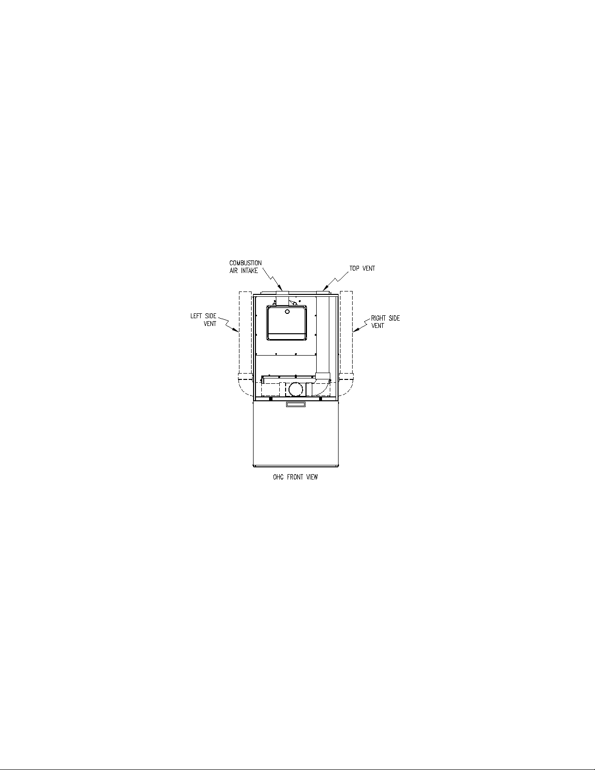
9. The furnace comes with two 3” street elbows. The first street el shall be affixed to the secondary
outlet collar either for left or right hand venting direction. First slide the black radiator hose
(parts bag) over the metal exhaust collar. Next, slide 2 band clamps over the radiator hose. Then
insert the PVC street el into the collar making sure to push the elbow all the way in until it stops.
Finally the band clamps can be positioned and tightened. If you are venting left or right, simply
continue venting with 3” PVC making sure to seal all connections. If you desire to vent thru the
top right of the cabinet, utilize the second street el and line it up accordingly. (See Figure 1)
Fig-1
10. Use a saw designed to cut thermoplastic pipe. All cuts should be made at right angles to the pipe
wall. Smooth jagged edges and remove all burrs and strings. Clean all pipe surfaces at connections
using a fine abrasive material or approved PVC cleaner (primer). Secure all pipe joints using suitable
permanent PVC pipe solvent cement. Joints are NOT to be made by simply gluing raw edges of
butted together vent pipe.
Notice: Piping joints inside the fu rnace vestibule should be sealed with si licone caulk, rather
than pipe cement, to allow for disassemble and removal of piping, if necessary, during
maintenance.
Notice: Use silicone caulk to seal the p ipe to the metal air intake collar on the burner, and then
secure with a sheet metal screw.
11. Vent connections shall be visually checked for leakage.
12. Vent pipe passing through an unheated space shall be insulated with 1-inch thick, foil-faced
6
Page 10
fiberglass insulation, or equivalent, to prevent freezing of condensate within the pipe.
13. No clearance is required from the outer surface of the thermoplastic piping to combustible materials
for fire hazard prevention. No clearance is required from the outer surface of the ventor assembly
either.
14. When attaching the 3” PVC to the burner combustion air inlet collar, first apply a bead of RTV
sealant to the burner inlet collar only to ensure an airtight seal. Next, affix the PVC to the collar
with a ¾ x #8 sheet metal screw. This can be driven right into the collar and may protrude
into the airway.
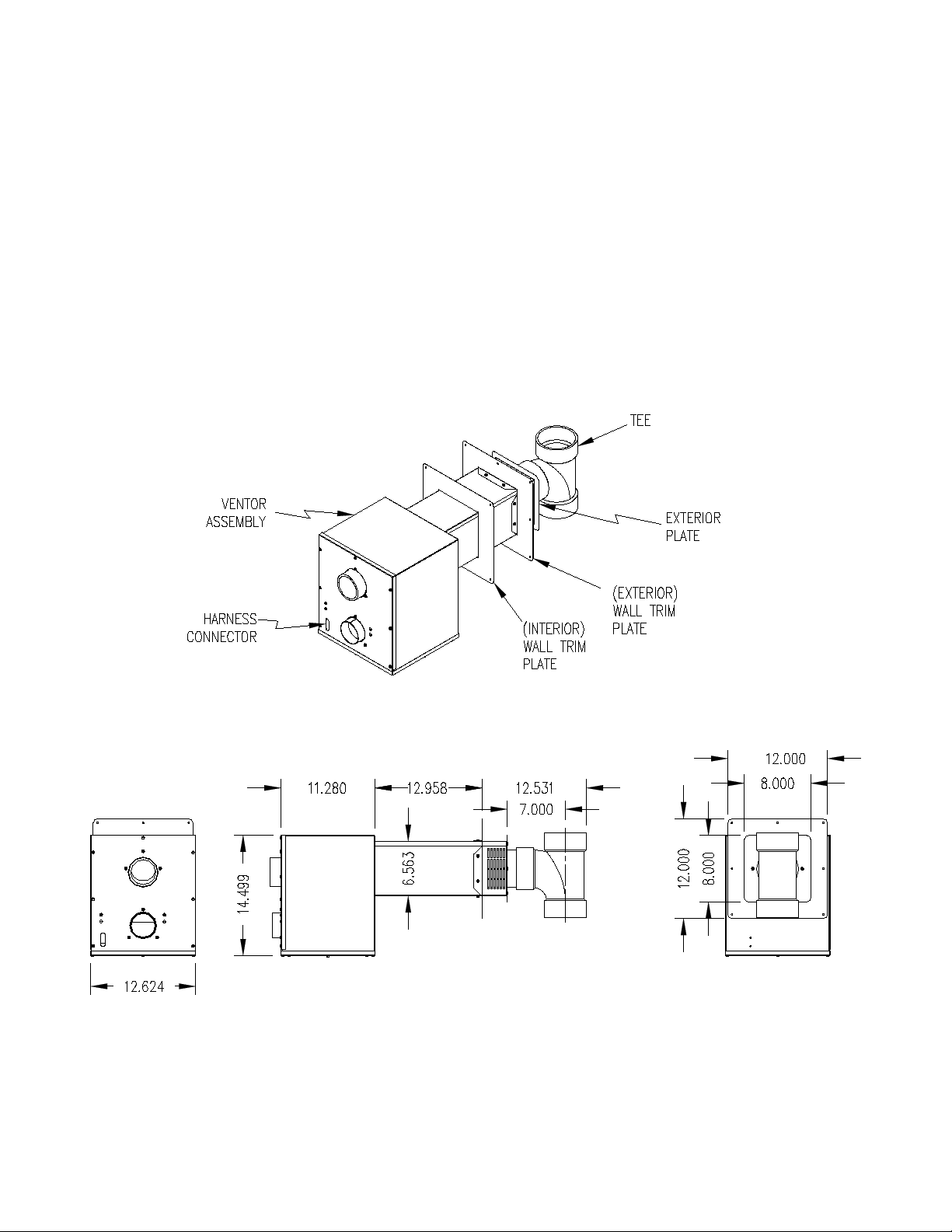
B. INSTALLATION OF VENTOR:
Fig-2
7
Page 11
NOTICE: Ventor assemb ly must be installed so that it is level. If unit is not level, condensate will
leak in to ventor box thru inducer and potentially freeze.
1. The OHC must be installed with the side-wall ventor/ blower assembly. Do Not attempt to operate the
OHC without the ventor assembly as this could result in damage to the appliance or home.
2. No clearance is required from the outer surface of the ventor assembly to combustible materials
for fire hazard prevention.
3. The ventor is designed to fit in between the joist space of 16 O.C.
4. Maximum wall thickness for the ventor assembly is 12”.
Fig-3
5. Remove vent system components from box and inspect for damage. If the carton has been crushed
or mutilated, check components very carefully for damage. DO NOT install if any damage is apparent.
6. Remove the vent tee from the vent pipe. Set the tee aside for now. Remove the exterior plate also.
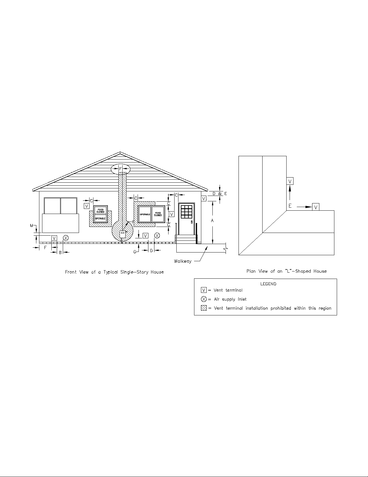
7. See Fig. 3 for vent terminal location. As a general rule, location of the termination of the venting
system should be installed in accordance with the National Fuel Gas Code, ANSI Z223.1,
manufacturer’s recommendations, and/or local codes that are applicable. Refer to the following
requirements or See Fig. 3 for typical locations.
8
Page 12

A. The exit termination of the draft system shall not be less than 7’ above grade when located
adjacent to public walkways.
B. The venting system shall terminate at least 3’ above any forced air inlet located within 10’
horizontally.
C. The venting system shall terminate at least 4’ horizon tally from, or 1’ above an y door, window or
gravity air inlet into the building.
D. The vent termination sh all be located at least 12” from any opening throug h which vented gases
could enter the building.
E. The vent termination point shall not be installed closer than 3’ from an inside corner of an L-shaped
structure.
F. The vent termination should not be mounted directly above, or within 4’ horizontally from an oil tank
vent or gas meter.
G. The bottom of the vent tee outlet shall be located at least 12” above finished grade.
8. After determining the location of the venting system termination point (See Diagram A), cut a hole in
the wall 7” x 7”.
9. Mount the ventor assembly through the wall opening. Fasten the exterior trim plate to the ventor body
with the provided screws and a bead of silicone sealant. Then secure the trim plate to the outside wall
with silicone sealant and the appropriate fasteners. Install the 4” PVC Tee as shown in Fig. 2 using
silicone sealant and a sheet metal screw to secure.
10. Use plumbers strapping or equivalent means to support the ventor main body. When supporting the
main body, care must be taken to ensure the unit is level.
11. The 25” cable provided with the ventor connects power from the furnace to the ventor blower and
pressure switches. The molex connection plugs in to the ventor assembly connection, (See Fig. 2).
The other end is connected to the furnace plug. The cable should be securely supported.
12. If local codes require that the cable be run through a conduit, remove the molex end with a molex pin
removal tool or equivalent. Care should be taken to not damage the pins. Run the cable through the
conduit and then replace the molex plug.
13. Connect the 3” PVC exhaust pipe to the ventor exhaust connection with a 3” coupling. Use silicone
sealant to seal and a sheet metal screw to secure.
14. Connect the 3” PVC combustion air pipe to the ventor opening with 3” pipe. Use silicone sealant
and a sheet metal screw to secure.
9
Page 13
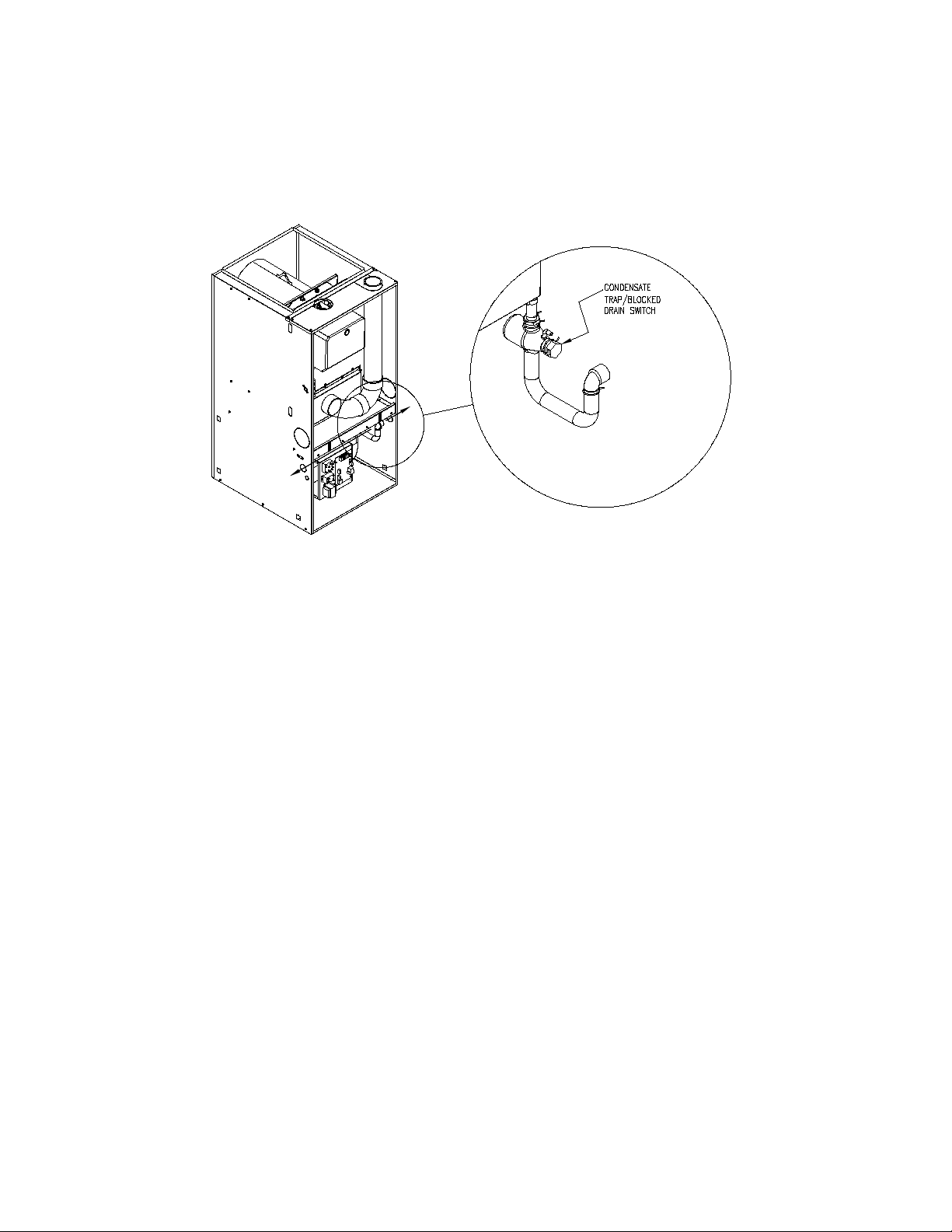
C. Condensate Drain Line Connections:
Fig-4
1. The trap/blocked drain switch assembly comes pre-mounted to the underside of blower pan just
below the secondary drain port on the right side of the furnace. Prior to installing the drain, the PVC
elbow must be sealed to the plastic trap with silicone and then the spring clamp applied. This
positioning of the elbow can be turned to right for exiting the right side casing or rotated 180
exit the left side of the furnace. In either case, secure the desired length of ½” PVC to exit the drain
line hole in the appropriate side casing. The knock-out must be removed first and then the grommet
included in the parts bag must be used to seal the PVC to the side casing.
0
and
Notice: It must be noted that the condensate drain line cannot exit the furnace on the same side as
the filter rack due to interference.
2. Plan, source, and install a condensate drain line using ½ diameter PVC (polyvinyl chloride)
thermoplastic pipe and pipefittings. Route the line in the shortest possible manner to reach
a nearby drain. Secure all joints using PVC cement. For gravity drainage, the condensate drain line
must maintain a minimum ¼ inch per foot downward slope toward drain. The drain line must be
watertight, supported and secured such that it cannot be easily moved.
Notice: If an air conditioning condensate drain line is combined with the furnace condensate drain line,
the air conditioning evaporator coil must have a separate trap installed ahead of the connection joint.
3. The OHC furnace is equipped with a blocked drain switch to prevent the furnace from continued
operation in the event of a blocked or slow draining drain. This switch is wired in series with the T & T
circuit (see wire diagram page 54 for details) and will open if the water level gets too high. This is non adjustable and cannot be by-passed.
10
Page 14

4. A condensate pump may be required when:
• a suitable drain is not present,
• the drain is above the trap outlet level on the furnace, or
• the drain line cannot be sloped downward its full length to the drain.
If gravity drainage of the condensate from the furnace to a drain is impractical for any of these
reasons, a condensate pump (part #350225) is available from Thermo Products. Follow the pump
manufacturer’s instructions for proper installation.
CAUTION: Continual exposure to condensate may injure plants and damage certain building
5.
materials, including metal, wood, stone, and concrete.
Flue gas condensate is slightly acidic with a pH of about 3.5. (A pH level of 7.0 is considered neutral.
Carbonated cola drinks with a pH of 3.1 are actually slightly more acidic than condensate.) If local
codes require an acid neutralizing kit, a kit is available from Thermo Products under part no. 320095.
Follow the instructions enclosed with the neutralizing kit for proper installation.
6. The condensate piping in the furnace and the drain system should be flushed out at the start of every
heating season. This will ensure trouble free operation and will keep the acidity level well above a pH
of 3.4, i. e. more towards neutral.
To flush the condensate drain system, follow these steps.
a. Turn off electrical power to the furnace at the disconnecting switch and adjust the room thermostat
to “OFF”, or to the lowest temperature setting.
b Flush the drain system by removing the drain hose from the secondary heat exchanger coil drain
nipple and running tap water into the open end of the tubing. Run at least a quart of water through
the drain system or more, until the water leaving the drain system is clear and colorless in color and
free of any particulate matter.
c Replace the drain tubing by pushing it firmly onto the nipple. Make sure the spring-type hose clamp
is returned to the original position to prevent leaks.
d. If any of the electrical controls are inadvertently wetted during the flushing process, dry them with a
soft cloth and wait 24 hours before operating the furnace.
e. Adjust the room thermostat to the “HEAT” position, or to the desired temperature, and restore
electrical power to the furnace.
D. DUCT WORK/AIR CONDITIONING:
Design and installation of the duct system should follow the current guidelines of the Air Conditioning
Contractors of America (ACCA) or the American Society of Heating, Refrigeration and Air Conditioning
Engineers, Inc. (ASHRAE). Refer to the Residential Duct Systems, Manual D, from the ACCA, and the
ASHRAE Handbook Fundamentals volume, from the ASHRAE, for recommended practices in the duct
system design and installation. To obtain copies of these publications for a fee, contact the ACCA and the
ASHRAE, at the addresses given in Appendix A of this manual.
All furnaces are tested over a range of external static pressure that simulates the airflow resistance of the
ductwork, fittings, and diffusers connected to the furnace for a typical (average) duct system. The furnace
11
Page 15
blower and blower motor have been selected to work successfully against the following range of duct
system resistance.
Recommended range of duct system resistance for all models: 0.2 to 0.5 in. W. G. external static
pressure.
Due to the need to maintain an adequate supply of combustion and ventilation air, the furnace shall not
be installed in small room without return air duct system. A duct the full size of the furnace return aid
opening shall extend to a location outside the furnace room.
If the furnace is used in connection with summer air conditioning (cooling), the furnace should be installed
in parallel with, or on the upstream side of, the evaporator coil to avoid water vapor condensation in the
furnace heat exchanger. If the cooling unit is installed in a parallel flow arrangement, dampers (or other
means used to control airflow) should be provided to prevent chilled air from entering the furnace. If such
damper is manually operated, it must be equipped with a means to prevent operation if either unit, unless
the damper is placed in either the full heat or full cool position.
NOTICE: Return air grilles and supply r egisters in the air distribution system should n ever be
obstructed.
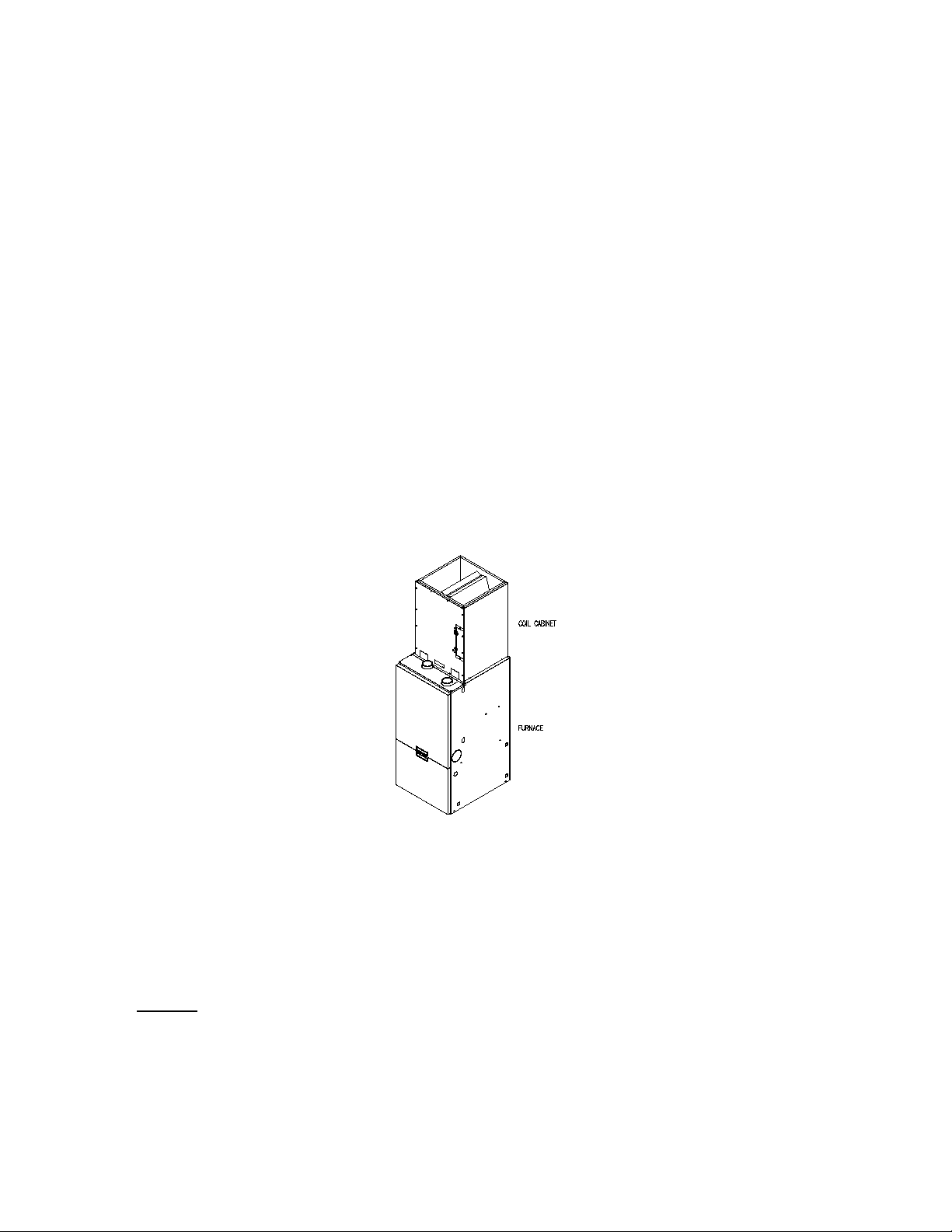
The duct system shall be designed for the maximum CFM requirements of the installation
whether it is for heating of cooling. Two common rules are as follows: 1.) 400 CFM/ton cooling
2.) 14 CFM/1000 BTU’S heating for 55
0
-850 Temp. Rise. The most common location for the
A-shaped coil (A style) is shown in Fig. 5.
Fig-5: Furnace with coil cabinet
NOTICE: The minimum coil pan clearance for a sectional or drum type heat exchanger is three inches
unless specified otherwise by the individual coil manufacturer.
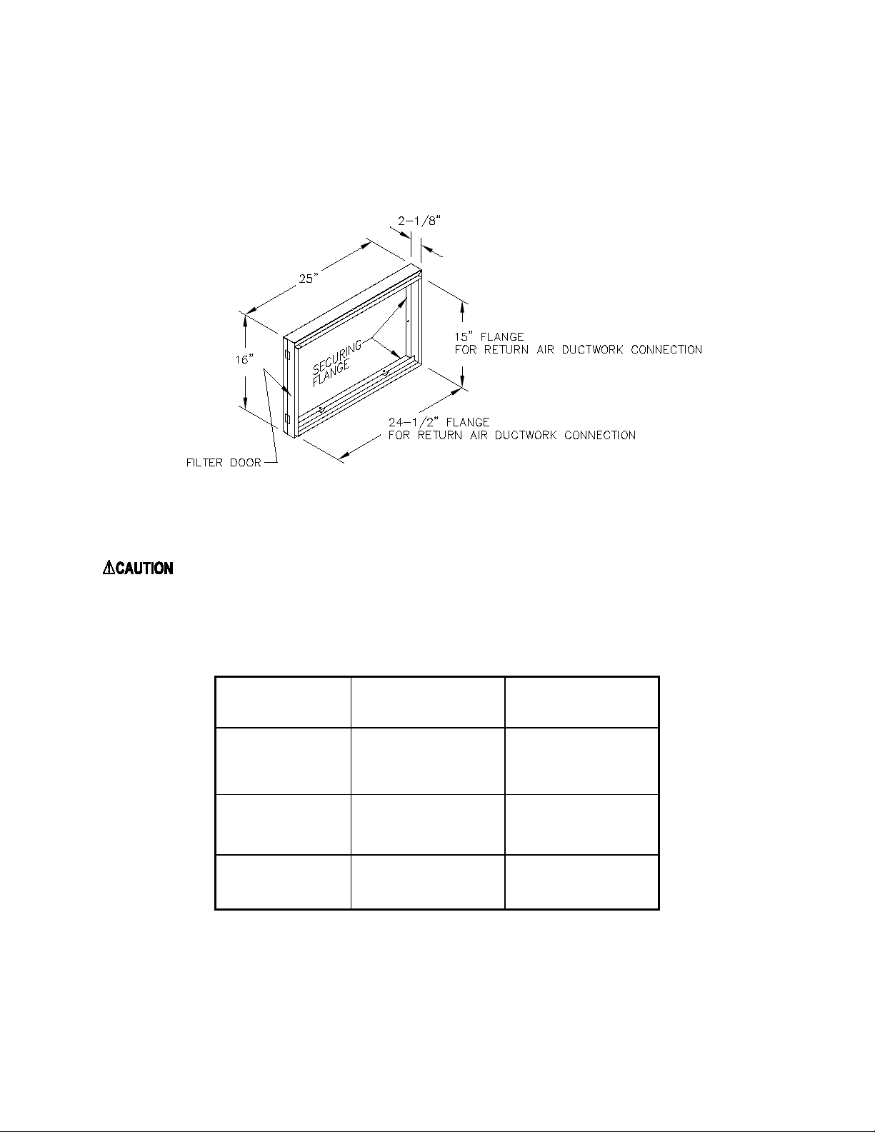
E. Air Filter Mounted External to Furnace:
On highboy furnaces, it is necessary to cut the return air opening in the side, rear casing or base,
depending upon the needs of the specific installation.
The filter rack provided with the furnace, refer to Fig. 6, can serve as a template to scribe a mark for the
return air opening on the casing. Place the filter rack on a side casing approximately one inch up from the
bottom of the furnace and centered from side to side. Place the securing flange against the casing when
locating the return air opening. For your convenience, (3) locator knockouts have been placed at the
proper locations on both the left and right side casings. Cut the opening to the O. D. of the knock-outs.
12
Page 16
Maximum
(ft/min)
Model Number
*Thermo Products
Now the filter rack can be anchored to the furnace with screws or pop-rivets through the securing flange
of the filter rack.
Connect the return a ir plen um to the f ilter rac k and sli de the f ilter into p lace. Dim ensions for adapti ng the
return air plenum to the filter rack are provided (See Fig. 6).
Note: Filter rack and condensate drain must be on separate sides of the furnace.
Fig-6 A typical filter rack and dimensions for the OHC furnace.
: Failure to comply with minimum filter installation requirements may affect the
performance and/or void the warranty on this unit.
If a method other than Thermo Pride filter racks is selected for retention of the filter and/or use of a
different filter type is desired, refer to Table 2 below for minimum sizing guidelines for selecting filter for
the unit.
Filter Type
Supplied
Air Velocity
600
OHC*
384 in
2
Permanent
Standard
500
Permanent
Disposable 300
461 in
768 in
2
2
Table 2: Minimum Required Filter Area (in square inches)
* The Thermo Products supplied filter can be cut to size to fit other filter retention systems as
long as the minimum size requirement is met.
13
Page 17
THERMO
RIELLO
LENGTH
MAXIMUM
SHIPPED
OIL
F. LIMIT POSITION AND LOCATION:
WARNING: The predeterm ined limit locations on all of the Ther mo Pride oil f ired furnaces have b een
tested and approved b y Thermo Products, LLC. An y attempt to relocate these saf ety controls or replace
these safety controls with a control that is not approved, or is incompatibl e, may result in p ersonal injur y,
substantial property damage or death.
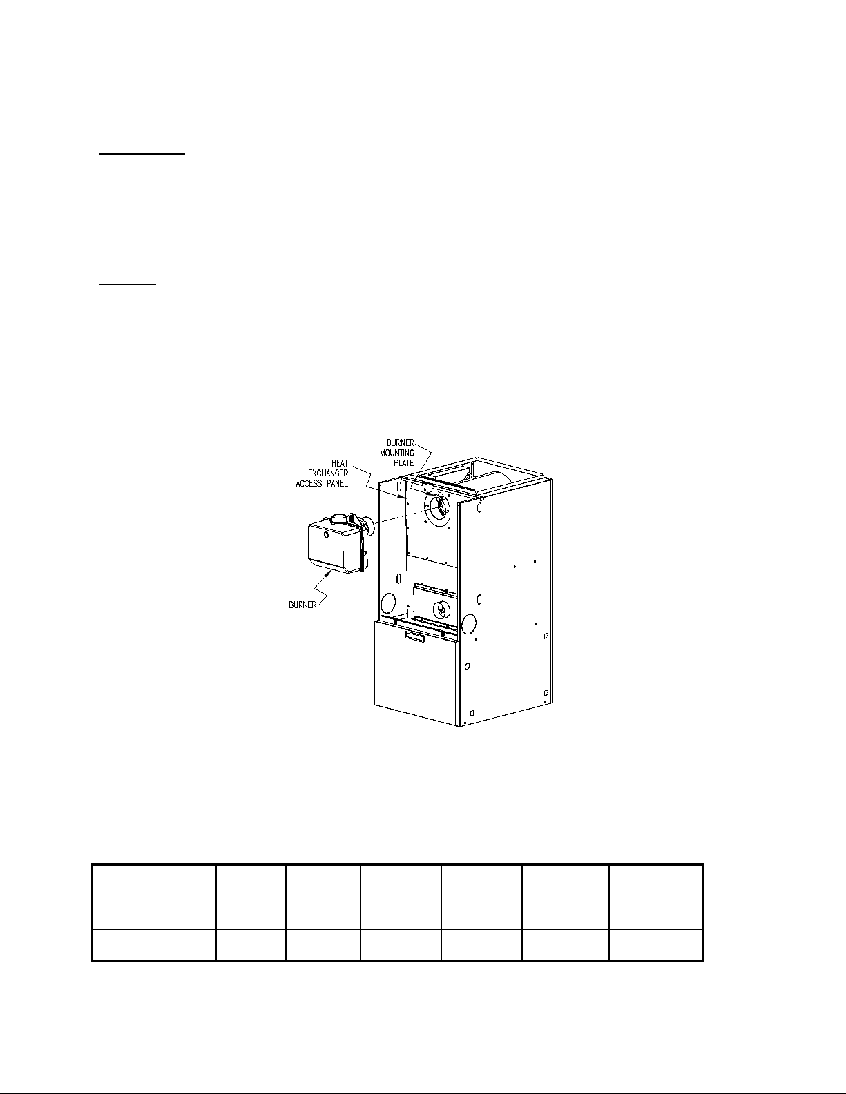
G. BURNER INSTALLATION:
NOTICE: This furnace comes with a Riello BF3 burner preinstalled from the factory. If there is a need to
remove the burner prior to installation or during service, the following explains how the burner is inserted
and mounted.
The oil burner is mounted on three stud mounting bolts on the mounting plate covering the opening in the
front of the heat exchanger. This unit is designed with a pre-positioned chamber. There is no insertion
adjustment necessary. The unit requires only the mounting of the burner. Insertion is pre-determined.
The top panel is removable by taking out the four screws for easy access to the burner and the piping.
Replace this panel prior to operating the furnace.
Fig-7
H. BURNER SPECIFICATIONS AND APPLICATIONS:
The BF3 Riello flame retention oil burner is the only oil bur n er th at can be used on the OHC.
PRIDE’S
FURNACE MODEL
OHCFA072DV4R C8511373 380789 BF3-4.5”
BURNER
SPEC NO.
AMULETTE
BURNER
MODEL &
TUBE
Table 3: Riello burner specifications
NOZZLE
SIZE**
0.50X60° H 0.50X60° H
14
NOZZLE SIZE
PUMP
PRESSURE
(PSIG)
145
Page 18
°
OHCFA072DV4R***
.50
THE NOZZLE SIZE GIVES THE NOMINAL FLOWRATE, IN GPH, FOLLOWED BY THE SPRAY
ANGLE, IN DEGREE’S, AND THE SPRAY PATTERN, EITHER “H” FOR HOLLOW CONE OR “S”
FOR SOLID CONE. FOR EXAMPLE, A NOZZLE RATED AT 0.65 GPH @ 100 PSIG THAT PROVIDES
AN 80° SPRAY ANGLE AND A HOLLOW SPRAY PATTERN WOULD BE ABBREVIATED IN THE
TABLE AS “0.65 X 80
H”.
For more specific burner information, contact:
Thermo Products Tech Service Department
OIL NOZZLE CAPACITY CHART
UNITS
Rate shown achieved with 145 PSIG pump pressure for Riello.
* Based on #2 domestic heating fuel oil having heating value of 140,000 BTU per gallon.
** Based on AFUE of 95%.
*** It is recommended to use Low Sulfur or Ultra Low Sulfur #2 fuel oil or lighter.
For more specific burner information, specifications or service information, reference the training manual
enclosed with each Riello burner or contact:
NOZZLE SIZE
(GPH)
Riello
Table 4: Oil nozzle capacity
Riello Corporation of America,
5 Pond Park Road Hingham, Massachusetts 02043
Phone: (617) 749-8292
EQUIVALENT HEAT
INPUT RATE*
(BTU/HR)
75,000 72,000
EFFECTIVE HEATING
CAPACITY**
(BTU/HR)
I. OIL TANK AND PIPING:
: All local codes and ordinances take precedence with regard to selection and
installation of oil storage tank and oil supply (and return) lines. In the absence of local codes, all
tanks and lines must be selected and installed according to the instructio n s in th is manual and
the Standard for the Installation of Oil-Burning Equipment, NFPA 31-1997, or the latest edition.
In situations where the oil storage tank is installed at the same level with, or above, the burner, a single oil
supply line run from the oil tank to the burner will usually be adequate. No return line will be required. If
the oil tank is installed below the burner and the lift exceeds approximately 8-ft, an oil supply line and an
oil return line are recommended.
Refer to the Standard for the Installation of Oil-Burning Equipment, NFPA 31-2001, and the oil burner
operating instructions for detailed information on oil storage tank and oil supply/return installation.
NOTICE: We recommend installing a high efficiency oil filter, in the oil supply li n e, capable of
filtering 10 to 20 micron diameter (or preferable smaller) particles from the fuel.
15
Page 19

If available, the use of ultra-low or low sulfur (less than 0.0015% S and 0.05% S, by weight,
respectively), no. 2 fuel oil is highly recommended. Low sulfur fuel oil can help to significantly reduce
instances of blockage and corrosion of the oil burner fuel delivery system (especially the nozzle), the
furnace heat exchanger, and the flue gas venting system. Air pollutants emitted by the furnace and the
typical malodorous smell of oil combustion will be reduced.
1. The use of black steel pipe and malleable iron fittings or heavy wall copper is recommended for
all fuel oil service lines. Never use galvanized steel piping or fittings for any fuel oil lines.
2. Where practical, provide rigid supports for the piping.
3. If the piping size in a run must be reduced, use reducing couplings only. Avoid the use of
reducing bushings.
4. Remove all pipe thread burrs and inspect the pipe for dirt or other foreign material prior to
connecting. If present, remove any deposits in the piping and discard any excessively corroded
piping.
5. A readily accessible, design-certified, manual oil shutoff valve, with a non-displaceable rotor
member, shall be installed in the fuel oil supply piping within 6 feet of the appliance.
6. A pipe union, or flanged connection, shall be provided downstream from the manual oil shutoff
valve to permit removal of the appliance oil pump. Pipe unions must be the ground joint type or
flanged-jointed using a gasket resistant to the corrosive action of fuel oils.
7. Pipe dope or thread sealant design-certified to be resistant to the action of fuel oils should be
used on all threaded joints. Thread sealant should only be applied to the male member of a
joint. The first two threads on the end of the male member of each pipe joint should be clean
and free from thread sealant.
8. Connection of the oil supply and return line piping to the appliance should be made from the
left-hand side of the burner, facing the burner compartment cover.
9. When copper is to be used for fuel oil supply lines, use of continuous runs of heavy wall copper
tubing is recommended. Avoid running tubing against any type of h eating unit and across
ceiling or floor joists. If possible, install the tubing under the floor.
10. Where tubing is used for fuel oil supply lines, insure the tubing contains no kinks, sharp bends,
or collapsed regions where the ins ide cr oss -sectional area of the tube is greatly reduced. These
will excessively reduce the flow of oil.
11. Flared fittings should be used at all tube joints, when tubing is used for fuel supply lines. Do
not use compression fittings. Avoid the use of tube fittings in inaccessible locations.
The BF3 burner has been factory set-up for a two pipe system. This means the burner has been
equipped with a by-pass plug. To aid in the installation, twin street-ells have been applied to the burner
oil connections. It is recommended that the installation remain a two-pipe set-up. If there are issues of
difficulties in running a return line to the oil tank it is permissible and recommended to install a de-aerator
such as a Tigerloop Brand for this application. This will ensure there to be no lift issues or problems with
the installation and eliminate the need to run a return pipe back to the tank.
Burners are equipped with a single-stage, fuel pump. This type of fuel pump, when connected with a
supply line only, is satisf actory where the fuel suppl y is level with, or above the burner thus permitting
gravity flow of oil to the burner. If the tank is above the burner, and gravity oil feed to the burner is
permitted, a single line system may be used. The line should have a gradual slope downward of
approximately 1/2 inch per f oot, or more, from the tank to a point directl y below where it is connected to
16
Page 20

the pump. Pitching the line upward toward the tank will help prevent the form ation of air pockets in the
line.
J. ELECTRICAL WIRING:
: This appliance must be grounded in accordance with local codes, or in the absence
of local codes, with the National Electrical Code, ANSI/NFPA 70-1999, or the latest edition.
Electrical Connections
NOTICE: All field wiring must conform to local, state, and national installation codes.
A disconnection switch equipped with overcurrent protection rated at 15 A. (e.g. a time delay-
type fuse or inverse time, circuit breaker) should be installed in the service line for shutting
down and protecting the furnace and electrical system.
Since the furnace is entirely pre-wired at the factory, it is only necessary to connect the building
electrical service lines to the two (2) pigtail wires extending from the 2x4 junction box. The fan timer
board is mounted inside the furnace blower compartment. The service lines to the furnace should be
no smaller than 14 Ga., insulated copper wire with a temperature rating of 60
Connect an equipment ground wire to the furnace at the 2x4 junction box. If wiring
is run through metal electrical conduit, it may not be necessary to run a separate equipment
ground wire. Consult local codes and authorities for specific minimum requirements.
A two (2) wire connection to the room thermostat from the fan timer board is also
necessary. This is typically a low voltage (24 VAC) circuit. Consult the National Electr ical Code,
ANSI/NFPA 70-2002 or latest edition, for guidelines for proper wiring methods and materials for this
circuit.
Refer to the electrical diagrams contained in Appendix B of this manual for an electrical schematic,
a connection diagram, and operating instructions.
Room Thermostat
A room thermostat is not furnished with this furnace. However, a thermostat is required to properly
operate the furnace control system in a typical residential heating application.
The room thermostat should be located on an interior wall in the natural circulating path of the room
air.
The thermostat should not be installed in a location where it is directly exposed to,
• cold air infiltration, i.e. drafts from outside openings such as windows and doors,
• air currents produced by supply air registers, and
• heat from a nearby source, such as a fireplace, electrical appliances, lamps,
solar radiation, a wall enclosing warm air ducts, a chimney, or a flue gas vent.
0
C, or greater.
17
Page 21

Model
Voltage/Frequency
No. of Phases
(V/Hz/Ph)
OHC Full Load
Current (Amps) @
120 VAC
Supply/Return
Air Blower Full
Load Current
(Am ps) @ 120
VAC
Oil Burner
Assembly
Full Load
Current
(Amps) @
120 VAC
Maximum
Time Delay
Type Fuse
or Inverse
Time
Circuit
Breaker
Size
(Amps)
Minimum
Recommende
d 75 deg. C.
Copper
Power Wir ing
Size (AWG)
12
2.5
7.15 ECM
11.45
120/60/1
OHCFA072DV4
15
Table 5: Typical Electrical Requirements
Post-Purge Timer:
This furnace is equipped with a post-purge timer located in the blower compartment on the control panel.
It is pre-set at the factory for a 4 minute post-purge. This is designed to ensure that no residual heat or
combustion odors permeate back into the home. The 4 minutes has been deemed sufficient, however if
you experience the need for a longer post-purge, the device has 3 selectable settings; 4 minutes, 5
minutes and 7 minutes. By simply turning the knob to one of the remaining selections the post-purge time
will be effected.
Fig-7A Post Purge Timer
Electronic Air Cleaner (EAC) and Humidifier Installation:
The fan timer on this unit has designated terminals to control the operation of an electronic air cleaner
and/or humidifier. These terminals provide line voltage for the control of these accessories, refer to
Figure 8 on the next page. Connection between EAC and N6 provides a switched 115 vac to power an
electronic fan cleaner. The same-switched 115 vac is available between Fan and N7 and may be used in
conjunction with a humidistat to control a humidifier. These terminals are energized whenever the blo wer
is active.
18
Page 22

Fig-8: The Fan Control Module
NOTICE: It is important to confirm that the operating voltage of the humidifier or EAC being
installed matches the output of this c o n trol. If not, a field supplied relay or transformer may be
necessary to provide the proper control and supply voltage for the accessory being installed.
Refer to the manufacturer’s instructions for the humidifier or EAC for additional information.
Thermostat Anticipator Setting:
Proper control of the indoor air temperature can only be achieved if the thermostat is calibrated to the
heating and/or cooling cycle. Calibration will help to produce a more constant indoor temperature by
adjusting the length of the heating/cooling cycle to fit the application. A vital consideration of this
calibration is related to the thermostat heat anticipator.
The proper thermostat heat anticipator setting is 0.2 ampere. To increase the length of the cycle,
increase the setting of the heat scale; to decrease the setting of the heat scale.
Anticipators for the cooling operation are generally pre-set by the thermostat manufacturer and require
no adjustment.
L. Blower Motor Speed Selection
: Turn off the electrical power to the unit, before attempting to change supply air
blower speed wiring.
The heat rise is determined by the blower tap selection on the control board located in the blower
compartment. For this ECM system, the ¾ hp motor is equipped with 5 speeds. The unit is set for
a temp rise of 60
0
F. See table 6 for proper blower motor setup:
19
Page 23

ALTERATIONS REQ’D FOR A/C @ DESIGN EXTERN AL STATIC PRE SS URE
COOLING UNIT
Recommended CLG Speed
24,000
Med Low
Low
30,000
Med Low
Med Low
36,000
Med Low
Med
42,000
Med Low
Med High
48,000
Med Low
High
Static Pressure
Furnace Airflow (CFM) vs. External Static pressure (in. WC.)
0.1
0.2
0.3
0.4
0.5
0.6
0.7
Low
1018
959
917
857
794
706
638
ML
1180
1140
1075
1137
992
952
887
Med
1311
1276
1244
1202
1146
1122
1062
MH
1554
1524
1489
1440
1403
1360
1316
HIGH
1718
1688
1656
1620
1583
1554
1524
Furnace Motor Current Draw (Amp/Watts) vs. External Static pressure (in. WC.)
Low
1.8/141
1.9/148
2.0/154
2.0/160
2.2/168
2.2/175
2.3/181
ML
2.6/207
2.7/213
2.8/222
2.8/228
2.9/238
3.0/245
3.1/257
Med
3.4/283
3.5/293
3.6/301
3.7/310
3.8/318
3.9/326
4.0/334
MH
5.1/442
5.2/451
5.3/460
5.4/466
5.5/480
5.6/487
5.7/496
HIGH
6.8/593
6.8/603
7.0/613
7.1/624
7.2/631
7.3/642
7.9/655
Static Pressure
Temperature Rise vs. External Static pressure (in. WC.)
0.1
0.2
0.3
0.4
0.5
0.6
0.7
Low
69
70
72
77
83
93
103
ML
56
58
61
64
66
69
74
Med
50
52
53
55
58
59
62
MH
42
43
44
46
47
48
50
HIGH
38
39
40
41
42
42
43
OHCFA072DV4
Recommended HTG Speed
Speed Tap\
Speed Tap\
Low= Red
Med Low= Purple
Med= Blue
Med Hi= Yellow
High= Black
Table 6: Blower Motor Speed Setup
20
Page 24

Pilot (Tstat) Neutral Line
Yellow Wires
White
Red
T-stat terminals
White
Black
M. BLOWER CONTROLLER INFORMATION FOR ECM MOTOR
TERMINAL DEFINITIONS & FIELD WIRING
Burner Harness Connector P1
Pin 1- Limit switch connector.
Pin 2- 120 VAC Line connection.
Pin 3- Burner pilot contact.
Pin 4&5- 120 VAC Neutral connections.
Pin 6- Burner pilot contact.
Pin 7&8- From oil primary control.
Pin 9- Limit Switch Input (LSI).
Field Wiring to Burner
Harness Wires
Riello Connections
Thermostat / Humidistat connections
“C” Common / ground
“W” Thermostat call for heat
“R” 24 VAC to thermostat
“G” Thermostat call for fan
“Y” Thermostat call for cool
“DEHUM” Humidistat call for dehumidification (TXV systems ONLY)
Male quick connect terminals.
“S1-3” 120 VAC Hot
“N1-7” 120 VAC Neutral
“EAC” Electronic Air Cleaner (120 VAC) connection
“FAN” Fan On Signal
“X” 24 VAC from transformer
“C” 24 VAC common from transformer
“CC” Compressor Contactor
“CC_COM” Compressor Contactor Common
“LOW” Continuous Blower Speed
“HEAT” Blower heat speed tap
“COOL” Blower cool speed tap
Inputs
Power supplies
Line voltage is applied between the “S1” and “N1” quick connect terminals. 24 VAC Class II
Transformer secondary voltage supplied to X and C
Limit switch
The 120 VAC optically isolated limit switch input is connected on pin P2-1 & 9. Refer to the Heat
Mode section for the control operation.
Thermostat call for heat “W”
24 VAC thermostat input. A call for heat is recognized when the thermostat connects “W” to “R”. This
input has an indicator LED that will light when the control receives a call for heat. Refer to the Heat
Mode section for the control operation.
21
Page 25

Thermostat call for cool, “Y”
24 VAC thermostat input. A call for cooling is recognized when the thermostat connects “Y” to “R”. This
input has an indic ator LED that wi ll light when the c ontr ol receives a call f or cooli ng. Ref er to the Cool
Mode section for the control operation.
Thermostat call for dehumidification “DEHUM”
24 VAC thermostat input. A call for dehumidification is recognized when the humidistat connects
“DEHUM” to “R”. This input has an indicator that will light when the control receives a call for
dehumidification. Refer to the Cool Mode section for the control operation.
Thermostat call for fan “G”
24 VAC thermostat input. A c all for fan is recognized when the thermostat c onnects “G” to “R”. This
input has an indicator LED in that will light when the control rece ives a call for fan. Refer to the Fan
Mode section for the control operation.
Outputs
PSC Control
The control shall contro l a five-speed indoor blower motor. Rating sha ll be 10 FLA, 30 LRA @ 120
VAC. Connections are made via 0.250 x 0.032” male quick connect terminals labeled “HEAT”,
“COOL”, and “LOW ”. “HEAT ” is energized when t he heat spe ed blo wer is to r un. “CO OL” is ener gized
when the Cool speed blower is to run. “LOW” is energized durin g a call f or fan is received or a call for
dehumidification is received.
Oil Burner
Control
The control provides dedicated contacts to operate the T-T input of an oil primary control.
Rating shall be class 2 – 24 VAC pilot duty @ 24 VAC (< 200mA).
Power
The switched 120 VAC power f rom the LIMIT switch pass es through th e board between Pi ns 1 & 2
of connector P1.
Compressor contactor
The control provides s witched 24VAC to oper ate a co mpress or contactor. R ating shall be cl ass 2 – 24
VAC pilot duty @ 24 VAC (<200mA).
EAC (electronic air cleaner)
The control provides a 120 VAC o utp ut f or an electr on i c air c leaner. This output is energized whene ver
the fan motor is energized ( either lo w, heat or c ool spe ed) . Conn ec tio n is made via male quick connect
terminal labeled “EAC”.
Humidifier
The control provides a 120 VAC output for a humidifier. Connections are made to a male quick
connect terminal labeled “FAN”. The control does not switch this output, it provides a pass-through
connection from P1-7 from the switched primary voltage of the Burner Module.
Status LED
A red LED is provided to indicate a ny therm ostat input has been recogni zed by the mic roprocess or on
the control. See Diagnostic Features for a function description of operation.
22
Page 26

Thermostat Input LEDs
Four green LEDs are plac ed beneath their respect ive thermostat connec tions (W, Y, G and DEHU M) and operate whenever a call is present. See Diagnostic Features for a function description of operation.
Operating Modes
Standby Mode
All outputs are off and the contr ol is waiting for a therm ostat demand. T he thermostat inputs, and limit
switch are continuous ly monitored. The control ini tiates action when a therm ostat call is received or
limit switch opens.
Fan Mode
A call for fan (“G” ) is rec eived f rom the ther m ostat. If no other m ode is ca lling f or blo wer op eration, the
control will operate the f an relay (K4) and power the “Low” blo wer speed terminal. The fan mode will
be operated as long as the “G ” input is calling an d neither the Heat m ode nor the Cool m ode is calling
for blower operation. When the Heat and Cool modes call for blower operation, their respective
outputs will take precedence after their respective turn-on time delays have expired.
Cooling Mode
A call for cool (“ Y”) is received f rom the therm ostat. If the heat mode is not active or t he anti-short
cycle delay is not in effect, the control will energize the “C C” terminal and after a 10 sec ond power
demand conservation delay energizes the “COOL” speed blower terminal.
When the call for c ool is satisfied, the “CC” term inal is de-energized and t he cooling off delay of 45
seconds is started. Fort y-five seconds later the “COOL” speed blower term inal is de-energized and
the control reverts to Standby Mode.
Dehumidification Operation
If a call for dehum idification is rec eived while t he Cool Mode is active, blo wer speeds will be reduced.
The PSC “COOL” blow er s peed ter minal (1158-100 model on ly) will be de-energized and “Lo w” b lo wer
speed will be energized.
Anti-Short Cycle Operation
To prevent compressor short cycling, a call for cooling will be ignored for four minutes after the
termination of any cooling call. The anti-short cycle delay is also in effect at power-up.
Heat Mode
When a call for heat (“W”) is received from the therm ostat, if the “Co ol” m ode is n ot alread y act ive, the
“T-T” terminal is energi zed and the blower on dela y is started. The on-of f pattern of DIP switch SW2
(positions 1 and 2) selec t one of four blower on delay values (s ee Table 7). W hen the delay time has
elapsed, the “HEAT ” blower speed is energized. T he control remains in stead y heat mode until the
thermostat is satisf ied. When the call for heat signal is rem oved, th e “ T-T” terminal is de-energize d and
the blower off dela y is started. T he on-off pattern of DIP s witch SW 2 (positions 3 and 4) select one of
four blower off delay values (see Table 7). When the delay time has elapsed, the “HEAT” blower
speed terminal is de-energized.
23
Page 27

DIP SWITCH 2 SECTION STATE
BLOWER DELAY TIM ES
Motor Blower Speed
Three interc onnected blower speed outputs are provided. A “G” call f or fan will provide power to the
LOW speed tap onl y. A “W” heat call will pr ovide power to the Heat s peed tap only. A “Y” cooling call
will provide power to the Cool speed tap only.
In the c ase of thermos tat calls for “Y” and “W” together , blower speed selectio n will be determined by
the input that was firs t initiated. In the case where th e control is in a cooling m ode with both “Y” and
“W” inputs energized an d then the “Y” input is removed, th e cooling blower off time will b e executed
prior to the control switch ing into a heating mode. In t he case where the control is in a heating mode
with both “Y” and “W” inputs energized and then th e “W” input is rem oved, the heating blower of f time
will be executed pri or to th e control s witching into a c ooling m ode. In the case wher e a call f or fan “G ”
already exists and either a “W” or a “Y” call is initiated, the blo wer speed will switch to the resp ective
“W” or a “Y” speed following the blower on delay for that call.
The speed taps are inter connecte d and inter locked, o nly one spee d ma y be powered at an y one time.
When a speed is to be operated, th e speed select relays are operated to select the pat h to the motor
tap and then the enable re lay is operated to switch th e operating power to the selecte d motor speed
tap. If the speed of the running m otor is to be changed, f irst the enable rela y removes power fr om the
motor, the new speed is selected and then power is restored to the motor.
Blower On and Off Delays
Four He at blower on and four blower of f delays are selected by two dip switches for each functi on.
Refer to Table 7 for specific delay values.
1 2 3 4
OFF OFF 30
ON OFF 60
OFF ON 120
ON ON 240
OFF OFF 2
ON OFF 4
OFF ON 6
ON ON 8
ON - SEC OFF - MIN
Table 7: ON and OFF Blower Delay Time Switch Settings
24
Page 28

For Your Safety Read Before Operating:
TROUBLE SHOOTING
DIAGNOSTIC FEATURES
The control board is equipp ed with 4 gr een Input S tatus LEDs and 1 red Bo ard Status LED. T hese are
intended to provide a quick view into furnace performance without requiring a voltmeter.
The green Input St atus LEDs are driven by the “ Y”, “W”, “G”, and “D EHUM” inputs and are locate d
directly below those inputs. They will light to indicate the presence of these signals.
The red Board Status LED has two functions:
It will light when the board recognizes a valid input signal and will stay lit until all valid signals are
removed. This is intended to show that the board is functioning and able to respond to input signals.
It will flash rapidly whi le 120VAC is missing from the LIMIT switch. T his is intended to give a quick
visual indication of the High Limit switch.
N. STARTUP PROCEDURES:
A. Heating System
1. Initial Startup :
: Turn off power to furnace. Before the oil piping system is placed into service, it must
have been leak tested by a qualified heating contractor.
: For initial start-up of the appliance after installation, it may be necessary to purge the
air out of the oil line. A qualified heating contractor should do this.
Review the following items before the initial startup. It may be helpful to review the Sequence of
Operations in Section VIII of this manual, also.
a. Check all wiring for loose connections and proper hook-up. Refer to the connection diagram.
b. Leak test all field oil piping connections. Generally, this will involve pressurizing the oil piping
with air while being careful to isolate the oil tank at high test pressures. A qualified heating
contractor should perform this service.
c. Check to see that the vent terminal is correctly installed and the terminal openings are clear
and free from blockage.
d. Make sure the air filter is in place and relatively clean of dirt and debris.
e. Make sure the thermostat is set in the heating mode of operation.
• This appli ance does not have a pilot light. It is equipped with an ignition system that
• Do not use this appliance if any part has been under water. Immediately call a qualified
explosion may result causing property damage, personal injury or loss of life.
automatically lights the burner. Do not attempt to light the burner by hand.
service technician to inspect the appliance and to replace any part of the control system
and any oil control that has been under water.
: If you do not follow these instructions exactly, a fire or
25
Page 29

Operating Instructions:
i. STOP! Read the safety information above.
ii. Set the thermostat to the lowest setting.
iii. Turn off all electric power to the appliance.
iv. This appliance is equipped with an ignition system that automatically lights the
burner. Do not try to light the burner by hand.
iv. Rotate the manual oil shutoff valve to the “ON” position.
vi. Turn on the electric power to the appliance.
vii. Set the thermostat to the desired setting.
viii. If the appliance will not operate, call your qualified service technician or oil supplier.
To Turn Off Oil to Appliance:
i. Set the thermostat to the lowest setting and set the operating mode switch to “OFF”.
ii. If service is to be performed, turn off the electrical power to the appliance.
iii. Turn the manual oil shutoff valve to the “OFF” position.
2. Adjustment of Burner Combustion:
: Do not run the oil pump dry for more than five minute s, as irreparable damage may
result.
NOTICE: Read the burner operation and service instructions Manual before continuing.
To initially adjust and successfully service the oil burner in the appliance heating section, the following
test instruments are required:
• A smoke density measuring and rating device,
• A carbon-dioxide (CO
• A flue gas temperature measuring device (e.g., thermocouple or thermistor probe with readout
device),
• An analog or digital multimeter, and
• An oil pressure gauge capable of reading 0-150 PSIG.
3. Sequence of Operation for the OHC:
The OHC has been designed to operate under a negative over-fire pressure. This is accomplished in part
by the coordinated set-up of the Riello BF3 burner and the inducer blower which is installed in the ventor
assembly. The two devices work together for proper operation. The sequence of operation is as follows:
) or oxygen (O2) analyzer,
2
26
Page 30

1. Call for heat TSTAT closes sending 24 volts to “W”.
2. The 24 volt relay closes sending 115v to the inducer in the ventor assembly.
3. The inducer comes up to speed and provides flow and pressure which closes the pressure switch.
4. Upon this pressure switch closing, T & T are closed to bring on the burner.
To initially fire the oil burner, proceed in the following manner:
a. Turn the disconnecting switch, which provides power to the appliance, to the "OFF" position.
b. Set the room thermostat above room temperature.
c. Verify the oil tank is filled with sufficient fuel oil to operate the appliance.
d. Open all valves in the oil supply line to the burner.
e. Remove the burner compartment cover from the appliance.
f. Turn the disconnecting switch to “ON”.
g. Prime the pump to remove air in the oil supply line.
• See Riello Burner Man ua l includ ed.
h. The burner has been installed with the pump pressure pre-set to 145 psi, the turbulator set at 3
and the air gate set to 3. These are general preliminary settings and adjustments should be
made to ensure clean combustions for this application.
i. Replace burner cover.
j. The air adjustments can be made by removing the plastic plug on the top right side of the cover.
Turning the screw counter clockwise will increase the amount of combustion air. Turning the
screw clockwise will decrease the amount of combustion air. A small ¼ “ diameter hole should
be drilled in PVC just outside the furnace to insert the combustion sample hose. Remember to
seal hole after acquiring flue gas sample.
5. Burner now operates and can be properly set-up for clean combustion.
6. Blower comes on after delay on time.
Notice: To achieve proper combusti o n instruments must be used to secure CO
and smoke samples.
Notice: Heat exchanger oil will burn off on initial firing creating an unpleasan t o d o r. To prevent
this odor from occurring more than on ce, it is suggested the heating section be al lowed to run for
30 minutes, or until odor has dissipated.
or O2 readings
2
27
Page 31

k. CARBON DIOXIDE (CO
possible to achieve readings of up to 14% CO
lower CO
open the air plate on the burner until zero smoke is measured. A CO
recommended.
(or higher O2) reading with zero smoke measured. To achieve a lower CO2 reading,
2
) OR OXYGEN (O2): Take a CO2 sample from flue passageway. It is
2
(or 2% O2), but it is recommended to have a
2
of 11-1/2% is
2
For example, if a 13% CO
until zero smoke is measured with a 11-1/2% CO
Adjustment of the burner to achieve a slightly lower CO
(or 3.5% O2) is recorded at a trace of smoke, open the air shutter
2
(or 4.5 O2).
2
reading is recommended, although it
2
slightly reduces combustion efficiency, to keep the heating system within normal operating
conditions though external conditions may vary. Some “out-of- spec” conditions which may
adversely affect burner performance are, low oil supply temperature, dirty (contaminated) oil, low
heating content (BTU/gal) oil, cold heat exchanger surfaces, and downdraft conditions. By
adjusting the burner in this manner, an operational tolerance is established by allowing the
burner to function well, even under less than ideal conditions. This results in less service and
maintenance during a heating season.
l. Removing the draft over fire cap allows for flame inspection and over fire pressure
measurement. The over fire pressure will be negative and will vary depending on the final
combustion set-up. If the over fire pressure is positive, shut down the burner and make certain
the inducer is operating and that the vent system meets the installation requirements on page 9
and 10.
m. Temperature rise is equal to the supply air temperature minus return air temperature. Under
steady state operating conditions, the temperature rise across the heating section should be
0
approximately between 55
F and 850F. A higher temperature rise will slightly lower the heating
efficiency.
The supply air temperature should be measured in the supply air trunkline approximately 12 inches
downstream of the supply air outlet of the appliance.
0
NOTICE: Minimum temperature rise is 55
NOTICE: Minimum return air temperature is 55
F.: maximum temperature rise is 850 F.
0
F.
n. After final adjustments are completed, tighten all screws to fix the positions of the burner air
band and replace the plastic plug.
o. Check for the presence of oil leaks. Correct any leaks found.
p. Reassemble the burner compartment cover and replace the draft pipe cap.
q. Start and stop the unit several times while checking for proper ignition of the burner. The
flame should ignite and stabilize without any significant rumbles or pulsations.
28
Page 32

Fig-9
NOTICE: To achieve proper combustion and the efficiencies listed in sales brochures, instruments
must be used to secure CO2 or O2 readings.
3. Adjustment Of Heat Input Rate:
This appliance was shipped from the factory with one, fixed, main burner nozzle sized to produce the
input rate using no. 2 fuel oil at 145 psi. The input rate cannot be increas e d.
The main burner oil nozzle for this unit was selected based upon the following assumed characteristic
values of the fuel oil suitable for use with this appliance design:
1. For no. 2 distillate fuel (domestic heating) oil having a higher heating value of 140,000 BTU per
gallon and a specific gravity of 0.88 @ 60ºF. (or “gravity” of 30º API @ 60ºF.).
4. Setting Supply Ai r Temperature Rise:
: To avoid injury from moving parts or electrical shock, shut off the power to the
appliance before removing supply air blower compartment door and servicing this a p p liance.
The OHC is designed and wired at the factory for a blower speed during heating that should result in an
approximate temperature rise of 60°F. The temperature rise through the heating section, for any given
blower speed, may vary depending on a number of factors. A few of these factors are variations in, the
actual resistance of the duct system to airflow at any time, the return air temperatures, and the fuel oil
heating value.
Also, fouling of the heat exchanger surfaces will reduce temperature rise. In general, a lower temperature
rise through the heating section will result in higher heating efficiency.
29
Page 33

Temperature rise = supply air temperature - return air temperature.
After 15 to 20 minutes of continuous operation, the temperature rise through the furnace must fall within a
range of 55° to 85° F. If the outlet or supply duct temperature is too high, check to make sure the return
air filter is clean, the return air registers are free from obstruction, the outlet registers are properly
adjusted and clear, and the supply and return air ducts are open. The circulating air blower is not moving
enough air if the supply air temperature is still too high. Before proceeding further, turn off the power
supply to the appliance and remove the vestibule cover. The speed of the blower must be increased by
changing the switch setting on the control board, please refer to Table 6.
5. Checkout Procedure:
Before any system of oil piping is finally put into service, it shall be carefully tested to assure that it is
“gas-tight”, as indicated in the Heating System Initial Startup section of this manual.
NOTICE: All controls on the unit should be checked for proper fu n ctioning prior to the qualified
service personnel leaving the job s ite. Specifically the following should be checked:
a. With heating system in normal heating operation, check to make certain blower will start and stop
automatically under control of the indoor thermostat.
b. Check safety limit control as follows:
i. Shut off incoming power.
ii. Block return air opening or disconnect blower motor leads.
iii. Restore power to appliance.
iv. In the heating mode, set the thermostat above room temperature producing “a call for
heat”.
v. When high air temperatures are reached within the heating section, the high limit control
should act to shutdown the burner.
vi. Shut off the electrical power.
IMPORTANT: Remove blockage or reconnec t b lower motor and restore power.
c. Make certain the thermostat will automatically start and stop the appliance.
NOTICE: Heat exchanger oil will burn off on initial firing creating an unpleasant o d o r. To prevent
this odor from occurring more than on ce, it is suggested the heating section be al lowed to run for
30 minutes, or until odor has dissipated.
30
Page 34

III. USERS INFORMATION SECTION
A. OIL SUPPLY: Do not allow the fuel tank to run completely empty. During the summer, keep the tank
full to prevent condensation of moisture on the inside surface of the tank. If the fuel tank runs completely
dry, it may be necessary to purge the lines of trapped air. Contact a qualified technician to bleed the lines
and restart the burner.
OIL SUPPLY VALVE: Turn the oil supply valve off if the burner is shut down for an extended period of
time.
B. INSPECTION AREA
VESTIBULE: The furnace vestibule area or burner compartment should be inspected by removing the
front door of the furnace and looking for signs of excessive heat such as discoloration of components
materials damage, from rust or corrosion, soot or carbon build-up.
EXTERIOR OF FURNACE: The furnace exterior should be inspected for signs of excessive heat such as
discoloration of materials and damage from rust or corrosion.
VENT PIPE: The furnace vent pipe should be inspected for signs of holes in pipe, and leakage around
seams in pipe, indicated by soot or condensate streaks.
CAUTION: DO NOT ATTEMPT TO MAKE REPAIRS YOURSELF!
WARNING: The area around the furnace should be kept free and clear of combustible liquids
and material, especially papers and rags.
WARNING: NEVER burn garbage or refuse in your furnace. Never try to ignite oil by tossing
burning papers or other material into your furnace.
WARNING: Thermo Pride oil furnaces are designed to burn No. 1 or No. 2 distillate fuel oil, and
should be of low or ultra-low sulfur content.
CAUTION: DO NOT ATTEMPT TO START THE BURNER WHEN:
1. Excess oil has accumulated,
2. The furnace is full of vapors
3. The combustion chamber is very hot.
IF ONE OR MORE OF THESE CONDITIONS EXIST, CONTACT A QUALIFIED SERVIC E PERSON.
C. STARTING THE BURNER:
S
1. Turn the main service switch to "OFF" position.
2. Set thermostat substantially above room temperature.
3. Open shut-off valves in oil supply line to burner.
4. Turn service switch to furnace "ON". If burner starts and runs, but stops again on lockout, it may be
necessary to bleed the lines or make burner combustion air adjustments. Contact a qualified service
person to adjust and start burner.
D. FILTER CLEANING AND LOCATION:
WARNING: To avoid injury from moving parts, hot surfaces, or electrical shock, shut off the
power to the furnace before removing any fu rnace access doors to service the air filters.
31
Page 35

The air filters should be inspected each month and cleaned when dirty. Cleaning the air filters frequently
may reduce airborne contaminants from entering the furnace and depositing in the furnace, duct system
and home.
Fig-10
IV. INSTALLER'S INSTRUCTIONS TO USER:
After completing the installation , the installer shall inform and/or demonstrate to th e homeowner
the following items:
1. The location of these instructions. The instructions must be kept along with instructions for any
accessories in the plastic pouch with the appliance.
2. The location and use of the manual oil shutoff valve and appliance electrical disconnecting
device. The end user must be instructed to always shut off the electric power to the appliance,
before shutting off the oil supply.
3. The sequence of operation of the appliance.
4. The correct operation and maintenance of the appliance, as outlined in the Homeowner/User
Information and Routine Maintenance section of this manual.
5. That failure to maintain and operate this appliance in accordance with these instructions could
result in hazardous conditions, property damage, and bodily injury. It may also void the limited
warranty on the appliance.
6. Review with and encourage the user to read the label reproductions and all warnings and
instructions outlined on the front cover and in Sections I, II, and III, of this manual.
7. Recommend the user have a qualified heating contractor inspect the entire appliance at least once
a year. Inform the user of the frequency of inspection required for each item in the Dealer
Maintenance section of this manual.
32
Page 36

8. Inform the user to maintain adequate clearances around air openings into the appliance housing
and not to block or restrict the entrance of air into the condenser coil or the burner compartment air
opening.
V. DEALER MAINTENANCE:
SAFETY DURING SERVICING AND INSPECTION
: Personal injury or property damage could result from repair or service of this
appliance by anyone other than a qualified heating contractor. The user may only perform the
activities described in the Homeowner/User Routine Maintenance section of this manual.
: To avoid injury from moving parts, or electrical shock, shut off the power to the
appliance before removing blower compartment door and servicing this appliance.
: When servicing controls, label all wires prior to disconnecting. Reconnect any
removed wires correctly. Wiring erro rs can cause improper and dangerous operation.
Dangerous operation can result in injury or damage.
IMPORTANT: Verify the proper operation of this appliance after any servicing is performed.
A qualified heating contractor should perform the following maintenance procedures at the
beginning of each heating season. Correct any deficiencies at once.
A. GENERAL INSPECTION:
WARNING: Shut off oil and disconnect power before continu ing with this inspection.
1. Vent tee - Visually inspect the terminal for restrictions, loose or missing fasteners, external
damage, and carbon build-up. Clean the vent terminal if necessary. Repair any minor damage.
If necessary, replace a severely damaged vent tee.
2. Burner – Visually check the burner, and below the burner, for indications of oil leaks. Correct
any, if found. Remove the burner and gun assembly and measure the ignition electrode gap.
It should be set to 5/32 inch. Adjust it, if necessary. Clean any accumulation of dust, dirt, or
debris from the air shutter or air band openings. If necessary, clean housing and blower wheel
with a damp cloth. Use a vacuum to remove any lint or dust from motor assembly. Add a few
drops of non-detergent oil to each of the motor lubrication holes.
3. Combustion Chamber - Inspect the liner for deterioration, oil and carbon build-up. If the
accumulation of oil or carbon is significant, this is a strong indicator that the burner is out of
adjustment. Inspect the burner nozzle for partial blockage and excessive wear. Rep lace it, if
required. Check and adjust oil pump pressure, if needed. Refer to Initial Heating System
Adjustments section of this manual.
Note: Care must be given to ensure no damage occurs to the chamber insert. (Refer to Figure 11)
4. Heat Exchanger – Visually inspect the heat exchanger for excessive carbon (soot) build-up.
Refer to the Heat Exch an ger section of the manual.
33
Page 37

• Visually inspect the 4 heat exchanger tubes for excessive carbon (soot) build-up. Refer
to heat exchanger section of the manual.
5. Oil Filter – Replace the supply line oil filter cartridge with a new filter of the same type and
rating. Clean the body of, or mounting plate for, the oil filter.
6. Labels and Markings - Clean all appliance labels, markings, and instruction plates, as
necessary, and verify that all are still legible. Any illegible or missing markings must be
replaced. Replacements can be obtained by contacting Thermo Products.
B. HEAT EXCHANGER: CLEANING INSTRUCTIONS
WARNING: A qualified heating contractor must clean the heat exchanger.
At least once a year, inspect the heat exchanger for evidence of corrosion, pitting, warpage, deterioration,
and carbon (soot) build-up. A layer of soot on the inside of the heat exchanger will act as an insulator and
reduce heat transfer, resulting in less heating efficiency.
Also, look for loose or deteriorated gaskets and insulation around the vent pipe, the burner, and
accessible areas of the heat exchanger. If this ins pec t i on i nd icates h eat ex c hang e r clean ing is nec es s ary,
follow the heat exchanger cleaning instructions below.
WARNING: THE HEAT EXCHANGER MUST BE CLEANED BY A QUALIFIED SERVICE PERSON.
It is important to inspect and clean the heat exchanger once a year, or as necessary, to remove any buildup of soot. A layer of soot on the inside of the heat exchanger will act as an insulator and reduce heat
transfer, resulting in less efficiency.
1. To clean the heat exchanger, first turn off all power to the unit. Remove the vent connector, the
burner, and the burner mounting plates. Then place the heat exchanger cleaning shelf on the 3 bottom
bolts as pictured. (See figure 11).
2. With access to the inside of the heat exchanger through the burner area, it is possible to use a long,
flexible wire brush and an industrial type vacuum cleaner to remove any soot build-up. NOTE: A one inch
(outside diameter) vacuum cleaner hose will fit into the tubes.
To vacuum and brush the tubes of the heat exchanger, go through the front openings in both directions,
as shown in figure 12 on the next page.
3 Remove front cover of heat recovery coil by removing all of the mounting screws. Then carefully pry
the cover loose taking care not to bend the cover. Remove a couple of turbulators to give visual
inspection of both the tube and tabulator. If excess build-up of soot is found, the secondary coil will need
thoroughly cleaned.
4. The entire heat exchanger can be removed from the front by removing the separator. Next remove
both side block-off baffles. Then disconnect the drain hose. The heat exchanger will now be able to be
pulled straight out of the furnace with the aid of the two back support wheels.
5. The rear coil cover should now be removed as done in #3. Next remove all turbulators. The
secondary can now be thoroughly brushed and cleaned.
34
Page 38

6. Reassemble the secondary to its original state. Replace heat exchanger, coil block-offs, and
separator. Reassemble furnace to its original construction. Remount the burner combustion air inlet. Reconfirm combustion settings.
Replace any damaged or corroded components. All gaskets and insulation must be inspected,
and replaced, if they show any signs of damage.
Fig-11
35
Page 39
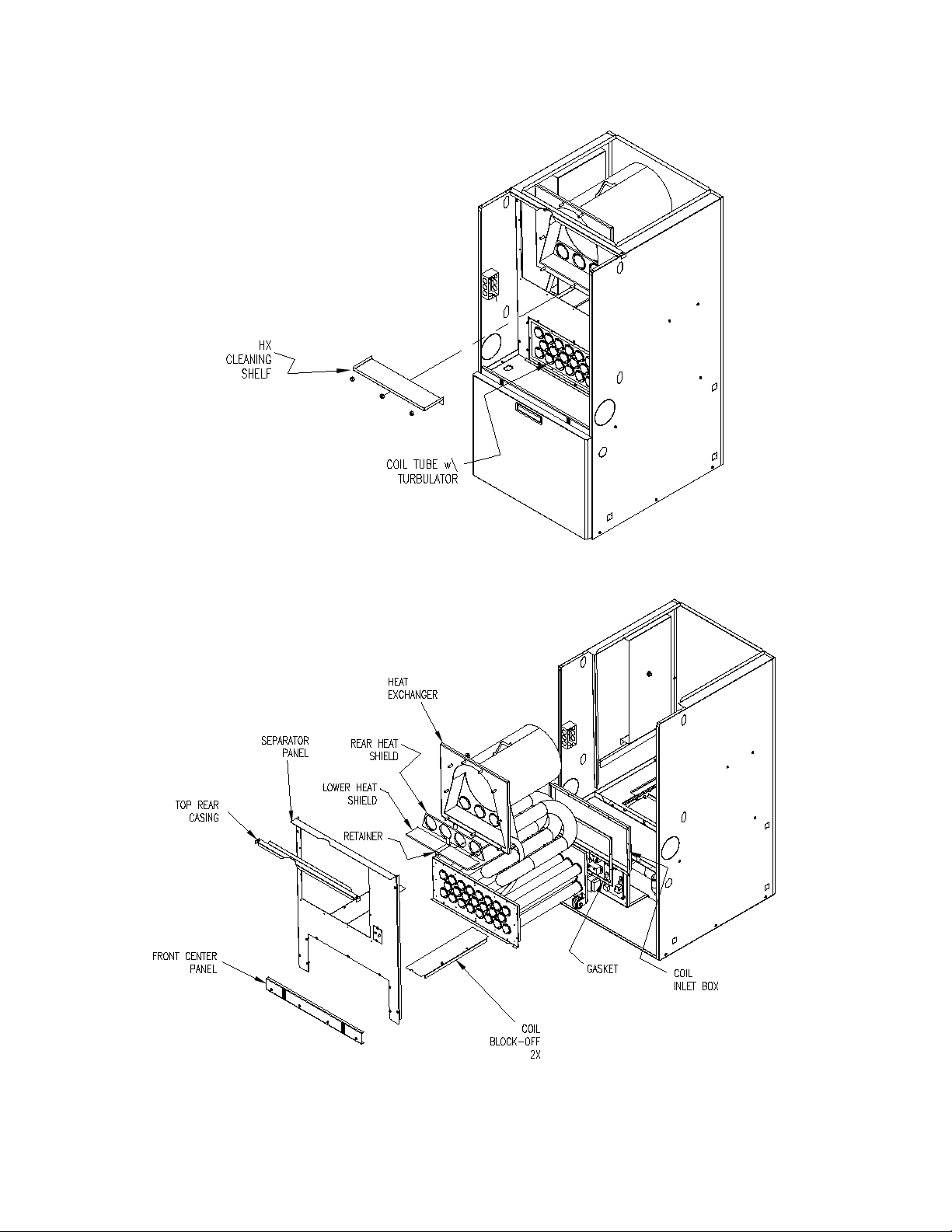
Fig-12
Fig-13
36
Page 40

CAUTION: Before troubleshooting, familiarize yourself with the start up and check out
procedures
NOTICE: After reassembling the appliance, check for fuel oil leakage from the supply piping.
a. Check proper operation of the ignition system and for proper combustion.
b. Observe the main burner flame. If the flame appears strange or abnormal in character, look for a
component or components that were not reassembled correctly. If the components have been
reassembled correctly, check for a blocked vent, malfunctioning combustion air blower or fuel pump,
and partially blocked burner nozzle.
D. ELECTRICAL SYSTEM:
WARNING: When servicing controls, label al l wires prior to disconnecting. Correctly reconnect
any wires removed during servicing. Wiring errors can cause improper and dangerous operation.
Dangerous operation can result in injury or damage.
1. Check all wiring for loose connections and any signs of damage, or unusual wear. Replace any
damaged or frayed wiring and tighten any loose connections.
2. Use a voltmeter, or a multimeter, to check for adequate voltage at the field connections when the
appliance operating.
3. Use an ammeter, or a multimeter, to check the current draws of the blower motor and burner assembly,
to assure they are not exceeding rating label current specifications for each component. Also, refer to
Table 5 in the electrical wiring section of this manual for electrical specifications on these components.
4. Check for correct operation and proper settings (if manually adjustable) of all controls.
E. SUPPLY/RETURN AIR BLOWER:
Check in the blower compartment for dust, dirt, debris, and for the presence of insects. Remove any
foreign material. Clean the blower wheel, housing, and compartment of dust and lint with a vacuum.
The blower motor has sealed bearings that are permanently lubric at ed. The blower motor bearings do
not require oil or any type of additio n al lubrication.
F. SUPPLY/RET U RN AIR FIL TER:
The filter rack will be located between the return air plenum and the return air opening on the side of the
furnace. This filter should be inspected regularly. When the filter is dirty, it should be cleaned or replaced
to assure proper heating/cooling system operation. Follow the cleaning, removal and replacement
procedure below.
Filter maintenance procedure:
Shut off the electrical power to the unit. Open the access door. Slide the air filter out of the filter rack.
Clean the filter by either vacuuming, rinsing with tap water, hosing, or dipping in an ordinary detergent
solution. After cleaning and drying the filter, replace the completely dry filter in the rack. If the filter has a
supporting mesh, the mesh side of the filter must be placed towards the furnace.
37
Page 41
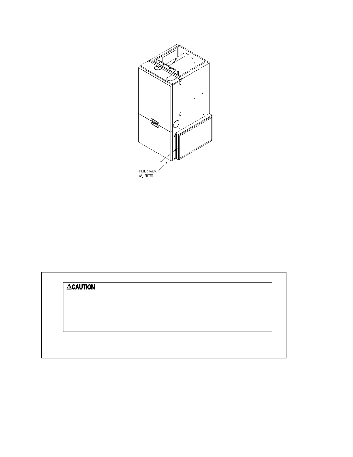
•
•
•
•
Fig-14
Filter replacement:
To ensure an adequat e replacem ent filter is selected, should the fi lter require re placing, ref er to Tabl e 2,
in Air Filters section of thi s manual, for the minim um filter areas required for dif ferent types of available
filters.
NOTICE: Remind the homeowner of the importance of monthl y filter inspections during operation
to ensure maximum operating efficiency.
G. EXTENDED APPLIANCE SHUTDOWN:
Primary reset has been engaged more than two times.
Excess oil has accumulated in the combustion chamber or beneath
the burner assembly.
The combustion chamber or the heat exchanger is full of fuel vapor.
The combustion chamber is very hot.
Should the appliance be shutdown or turned off for an extended period of time, several steps can be
taken to help insure a smooth and reliable restart of the heating system.
ON SHUTDOWN:
: Do not attempt to start burner when:
1. Close oil supply (or manual shutoff) valve.
38
Page 42

2. Disconnect all electrical power to the unit.
3. Fill the oil tank to reduce water condensation in the tank.
4. If the shutdown period will exceed one heating season, an oil stabilizer should be added to the oil
tank. Consult your oil supplier for recommendations.
ON STARTUP:
1. Have system inspected and started by a qualified heating contractor.
2. Check oil level in tank. If the tank has not been filled with fresh oil, inspect the remaining oil for
signs of contamination with water, algae, dirt or other impurities. If excessive, consult your oil
supplier for recommendations.
3. Change the oil filter cartridge and clean the canister.
4. Set the room thermostat above room temperature.
5. Open all valves in the oil supply line.
6. Open the inspection cover on the upper mounting plate.
7. Turn on the electrical power to start the burner. If the burner does not start, immediately reset the
manual overload switch on the motor (if so equipped) and the safety switch of the burner
primary control. Bleed air from the fuel oil line as soon as the burner motor starts rotating. To
bleed the fuel pump, attach a clear plastic hose over the vent plug, refer to Figure 15. Loosen
the plug and catch the expelled oil in an empty container. Tighten the plug when all the trapped
air appears to be purged. If the burner stops during bleeding, wait three to five minutes for the
control safety switch to cool. Then manually reset the switch. Continue bleeding the line until the
air is completely removed.
Fig-15
8. Follow the previous Initial Burner Operation procedures.
39
Page 43

VI. HOMEOWNER/USER INFORMATION AND ROUTINE MAINTENANCE:
WARNING: Never burn garbage or refuse in this appliance. Never try to ignite
oil by tossing burning papers or other material into the combustion chamber.
WARNING: Oil-fired appliances produced by Thermo Products are designed for
burning No. 2 distillate (domestic heating) fuel oil. Never use gasoline or a
mixture of oil and gasoline.
: Do not use this appliance if any part has been under water. Immediately
call a qualified service technician to inspect the furnace and to replace any part of
the control system and any oil control that has been under water.
: Should overheating occur, or the oil supply fail to shut off, shut off the
electrical power to the appliance, before shutting off the manual oil valve.
: The area around the appliance, including the top of the unit, must be
kept clear and free of combustible materials, gasoline, and other flammable
vapors and liquids.
: Do not attempt to make repairs yourself. Contact your local qualified
heating contractor.
Under normal conditions, this appliance will operate in either heating or cooling mode, depending upon
the mode of operation set at the thermostat. The unit will cycle on and off automatically, as required, to
maintain the air temperature within the residence as closely as possible to the thermostat setting.
However, in rare cases, the unit may shutdown automatically during a normal cycle or may not operate
under seemingly normal conditions.
If the unit will not operate in the heating mode, it may be possible to reactivate the unit by resetting
one of the burner controls. To attempt resetting of the burner controls, follow this procedure.
1. Turn the thermostat temperature setting down and set the operating mode to “OFF” or
“COOLING”.
2. Remove the furnace front door.
3. Check to see if the light on the burner primary is on. If so, the control may have “locked out”. To
recycle the control system, depress the reset button. Refer to Figure 16.
4. Replace and secure the furnace front door.
5. Set the operating mode on the thermostat to “HEATING” and turn the thermostat temperature
setting up.
40
Page 44

Fig-16
If this action does not reactivate the unit, contact a qualified service agency for assistance.
In general, if the thermostat is set in the heating mode, the heating system functions entirely
automatically. However, under certain circumstances, the appliance may not be able to fire the burner.
For instance, if the manual oil shutoff valve has been closed or the oil tank is out of fuel, the oil line may
have air trapped in it. It will be necessary to purge the air by bleeding the supply line from the tank to the
burner again for the heating system to operate. Refer to the instructions under the Extended Appliance
Shutdown section of this manual.
NOTICE: Thermo Products recommends that the user/homeowner, contact a qualified service
agency for assistance in bleeding th e fuel line(s) and lighting off the heatin g section.
The following maintenance points should be reviewed periodically to assure the heating and cooling
systems continue to function properly.
: Shut off unit and disconnect the power source before disassembling the unit.
: Never operate the appliance without clean air filters in place.
: This appliance requires air for combustion, ventilation, and cooling. Do not block or
obstruct air openings in the unit and th e air space around the perimeter of the unit.
1. At least every three months, under normal usage conditions, check and clean all air filters in the
appliance and, if present, in the duct system. If excessively dirty air filters are not cleaned, or
changed, poor system performance will result due to reduced airflow. Low airflow places
unnecessary strain on the compressor, possibly causing the system to shutdown on the
refrigerant high-pressure switch. Refer to Figure 14 for a sketch of the filter location.
2. Do not allow the fuel oil tank to run completely empty. During the summer, keep the tank full to
reduce condensation of moisture on the inside surface of the tank. If the fuel tank runs
completely dry, it may be necessary to bleed air from the fuel lines. Contact a qualified heating
contractor to bleed the lines and restart the burner.
3. Check the supply and return air connections to the appliance to insure the seals between the
duct and appliance and the appliance and home are intact. Check the ducts for any signs of
collapse, holes, or excessive corrosion. Repair or replace components as required.
41
Page 45

VII. TROUBLESHOOTING:
THIS SECTION IS ONLY TO BE PERFORMED BY TRAINED, QUALIFIED SERVICE
PERSONNEL, AND NOT BY THE FURN ACE OWNER.
NOTICE: Before troubleshooting, familiarize yourself wi th the Initia l Startup,
Checkout Procedure, and Troubleshooting Flowchart.
Refer to the appendices of this manual for an electrical schem atic, a connection diagram, flowcharts to
assist in troubleshooting, product specifications, and a replacement parts list follow for this appliance.
1. Check for 115VAC line supply voltage to the furnace. If there is no supply voltage, check fuses and
service switch.
CAUTION: When testing electrical equipment, always follow standard electrical procedures.
2. Make sure thermostat is calling for burner operation.
3. Check oil supply and make sure all valves are ope n.
The troubleshooting c hart beginn ing on the f ollowing page should help identif y the type of m alfunction or
deviation from normal operation. To use this diagram, just follow the instructions in the boxes. If the
answer is yes or the condition is true, go down to th e next box. If the answer is no or t he condition is
false, go to the box on the right. Con tinue chec king and answer ing questions and conditio ns in each box
until a problem and/ or repair is found. After any mainten ance or repair, the trouble shooting se quence
should be repeated until normal system operation is achieved.
42
Page 46

43
Page 47

44
Page 48

45
Page 49

46
Page 50

47
Page 51

COMBUSTION AND EFFICIENCY TESTING FOR THERMO PRIDE
OIL F IRED C ENTRAL FURNACES.
Complete this form for each Thermo Pride furnace ins talled. Read instruction
manual carefully before making tests. Retain this form with furnace.
CUSTOMER NAME
ADDRESS
CI TY, STATE
HEATING BURNER MO DEL NO. BLAST TUBE LENGTH AIR SHUTTER OPENING % OF MAX. (EST)
SYSTEM
COMBUSTI ON CHAMBER
CONDITION MATERI AL FURNACE MODEL
VENT SYSTEM DESCRIPTI ON
NUMBER OF 90
0
ELBOWS?
EXHAUST _____
INLET AI R _____
LENGTH OF STRAI GHT PI PE?
EXHAUST _____
INLET AI R _____
FUEL LI NE FI LTER FURNACE SERI AL NUMBER
COMBUSTION
INITIAL
TESTS
INSTA LLATIO N
SERVI CE SERVICE SERVI CE
CO2 IN VENT PIP E
DRAFT OVERFIRE
DRAFT IN VENT PIP E
SMOK E NUMBER
GROS S STACK TEMP
FUR NACE ROOM TEMP
NET STAC K TEMP
(GROSS STACK MINUS FURNACE ROOM TEMP)
EFFI CI ENCY
NOZZLE SIZE & SPRAY
OIL PUMP P RESSURE
OPERATI ON OF CONTROL S
BUR NER SAFETY CON TROLS
CHECK OIL FOR LEAKS
TESTS TAK EN BY
DATE
NOTES
INS TALLER NAME & ADDRESS
(OPER ATE BURNER
AT LEAST 10
MINU TES BEFORE
STARTI NG TESTS. )
48
Page 52

Appendix – A
Replacement Parts:
49
Page 53

ITEM DESCRIPTION TP PART #
1 AIR TUBE COMPLETE 380760
2 BLAST TUBE ONLY 380710
3 ELECTRODE ASSEMBLY 380712
4 PUMP 380633
5 MOTOR 380630
6 BLOWER WHEEL 380629
7 PRIMARY CONTROL 380449
8 PHOTO CELL 380628
9 INSULATING AMULET 380789
10
NOZZLE, .50 60°W 380387
11 COIL 380719
12 MTG FLANGE GASKET 330371
OHC BF3 RIELLO BURNER (380790 )
50
Page 54

51
Page 55
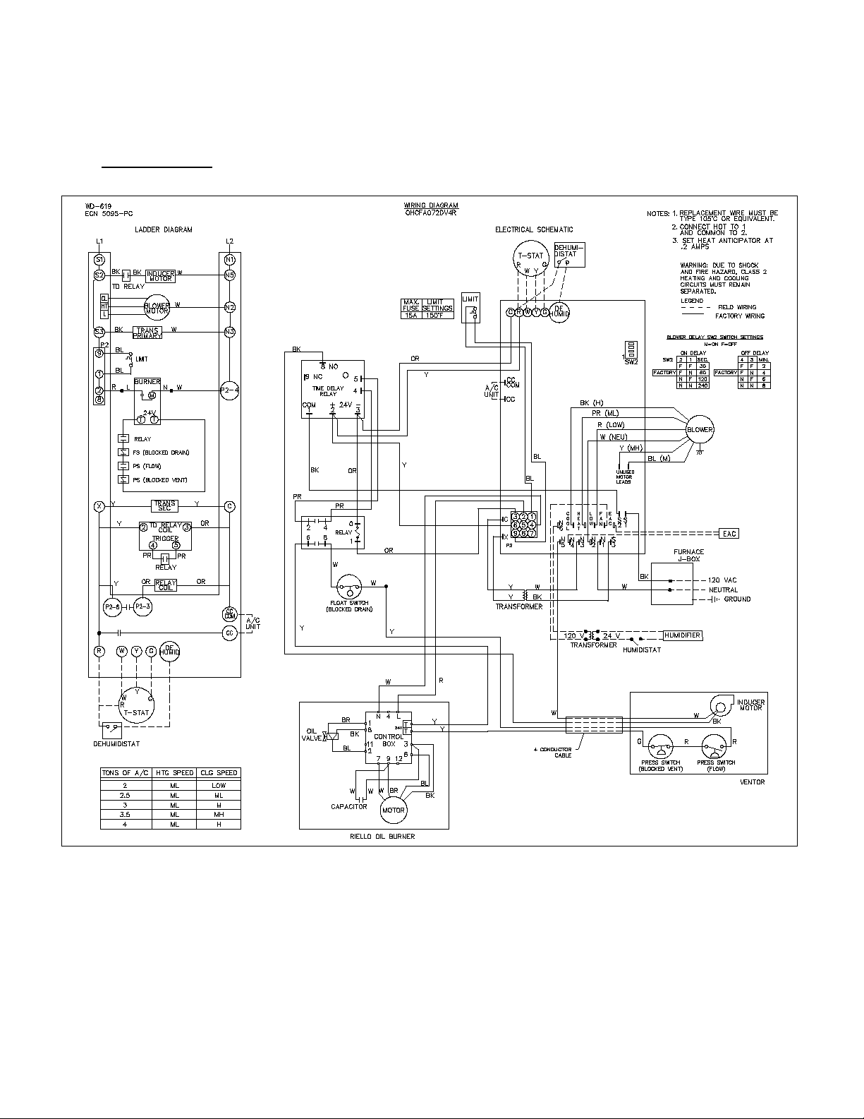
Wiring Diagram
OHCFA072DV4R
Appendix – B
52
 Loading...