

Page 1
INSTALLATION AND OPERATION MANUAL
FOR 2 – STAGE RIELLO BURNER
ADDENDUM TO ( Mo – 437 manual )
FOR USE WITH MODEL:
OH6FX072DV4
PLEASE READ THESE INSTRUCTIONS PRIOR TO INSTALLATION, INITIAL FIRING, AND
BEFORE PERFORMING ANY SERVICE OR MAINTENANCE. THESE INSTRUCTIONS
MUST BE LEFT WITH THE HOMEOWNER AND SHOULD BE RETAINED FOR FUTURE
REFERENCE BY QUALIFIED SERVICE PERSONNEL.
THERMO PRODUCTS, LLC.
BOX 217
NORTH JUDSON, IN 46366
PHONE: (574) 896-2133
MO-462
ECN 4865-MA MADE IN USA
Page 2
Riello 2-stage burner specifications and applications:
MODEL
PART
MTG. PLATE
PART NO.
MTG. PLATE
GASKET
PART NO.
**NOZZLE SIZE
OD6 2-STAGE
11700
330212
.70 X 45° W
NOZZLE
PART NO.
OIL PUMP
PRESSURE
130 LOW
170 HIGH
380702
BURNER G5D
BURNER
PART NO.
Table 8: Riello burner application
380529
THE NOZZLE SIZE GIVES THE NOMINAL FLOWRATE, IN GPH, FOLLOWED BY THE SPRAY ANGLE, IN
DEGREE’S, AND THE SPRAY PATTERN, EITHER “H” FOR HOLLOW CONE OR “S” FOR SOLID CONE.
FOR EXAMPLE, A NOZZLE RATED AT 0.65 GPH @ 100 PSIG THAT PROVIDES AN 80° SPRAY ANGLE
AND A HOLLOW SPRAY PATTERN WOULD BE ABBREVIATED IN THE TABLE AS “0.65 X 80°H”.
** NOTE: The reason the Riello burner nozzle sizes are smaller than the standard Thermo Pride burner nozzles
is that pre-set pump pressures are higher, therefore achieving the same firing rate with a smaller nozzle.
For more specific burner information, specifications or service information, reference the training manual enclosed
with each Riello burner or contact:
Riello Corporation of America,
5 Pond Park Road Hingham, Massachusetts 02043
Phone: (617) 749-8292
2 STAGE FIRING RATES
CAPACITY
FIRING
RATE
NOZZLE SIZE
Riello
INPUT RATE*
(BTU/HR)
EFFECTIVE**
HEATING
CAPACITY
HIGH CAPACITY
LOW CAPACITY
HIGH FIRE 106,250/170psi 90,000
LOW FIRE
HIGH FIRE 85,000/170psi 74,000
LOW FIRE
.70 X 45° W
85,000/130psi 74,000
.50 X 45° W
70,000/130psi 60,000
Table 9: Riello 2-stage firing rates
* Based on #2 domestic heating fuel oil having heating value of 140,000 BTU per gallon.
** Based on thermal efficiency of 84%-85%.
2
Page 3
MOUNTING THE 2-STAGE RIELLO BURNER:
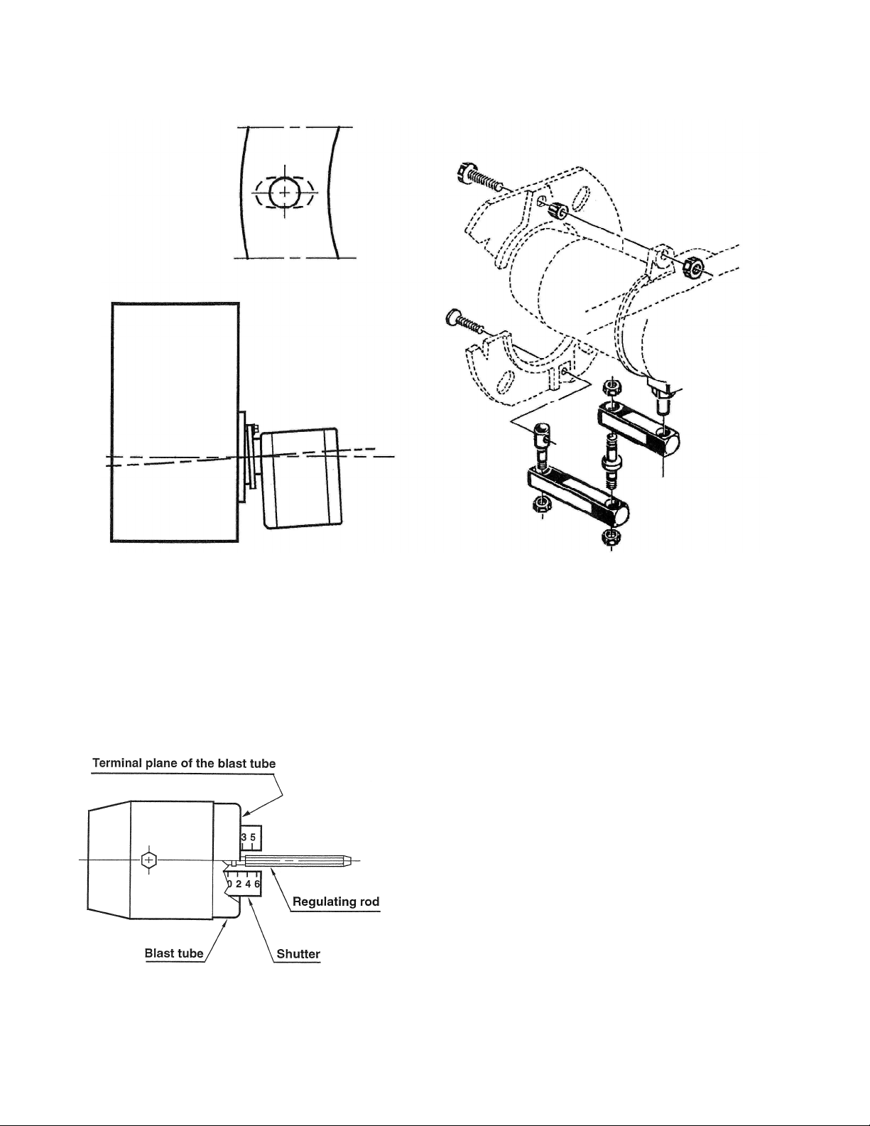
It is necessary that the insulation gasket be placed between the mounting plate and the burner flange. The
insulating gasket has six holes, which, if necessary, can be modified as shown. (see figure 14-1)
Figure 14-1: Burner gasket and mounting Figure 14-2: Burner fixing and hinge assembly
Verify that the installed burner is lightly leaned towards the button. (See figure 14-1) The burner is designed to
allow entry of the flexible oil-lines on either side of the burner.
COMBUSTION HEAD SETTING FOR 2-STAGE RIELLO BURNER:
This is done when fitting the nozzle, with the blast tube removed. It depends on the output of the burner and is
carried out by rotating the regulating rod, till the terminal plane of the blast tube is level with the set-point, as
indicated in the schedule.
Figure 20
In figure 20 the combustion head is set for an output of 0.75
GPH at 130 psi, while the shutter is level with set-point 2.5, as
required by the above schedule.
3
Page 4

The setting of the fan output according to the installation
should be done only through the air damper. Should you want
to adjust the setting of the combustion head, with the
burner running, turn the rod (1) with a 6mm wrench (2) as
follows:
TURN TO THE RIGHT: (SIGN + )
In order to increase the volume of air entering the
combustion chamber and thus diminishing its pressure.
There is a reduction of CO2 and the adhesion of Figure 21
the flame to the air diffuser disc improves.
(Setting advisable for ignitions at low temperatures).
TURN TO THE LEFT: (SIGN - ) Figure 21
In order to reduce the volume of air entering the combustion chamber and thus increasing its pressure. The CO2
improves and the adhesion of the flame to the diffuser tends to reduce. (This setting is not advisable for ignitions
at low temperatures).
In any case do not bring the combustion head setting more than one point away from that indicated in the
schedule. One set-point corresponds to 3 turns of the rod; a hole (3) at its end facilitates counting the number of
turns.
AIR DAMPER ADJUSTMENT:
The settings indicated in the schedule refer to the burner with its metal cover fitted and the combustion chamber
with “zero” depression. These regulations are purely indicative. Each installation however, has its own
unpredictable working conditions: actual nozzle output; positive or negative pressure in the combustion-chamber,
the need of excess air, etc. All these conditions may require a different air damper setting.
It is important to take account of the fact that the air output of the fan differs according to whether the
burner has its metal cover fitted or not.
Therefore we recommended to proceed as follows:
• adjust the air damper as indicated in the schedule (3);
• mount the cover, simply by means of the upper screw;
• check smoke number;
• should it become necessary to modify the air output, remove the cover by loosening the screw, adjust the
air damper, remount the cover and finally recheck the smoke number.
The burner is provided with a hydraulic device controlled by the economizer which reduces the max. output of oil
and air by approximately 70%.
4
Page 5

Figure 22
1st STAGE ADJUSTMENT:
Adjustment of air shutter: place the small plug (9) of the economizer (10) into the position I (Item A). In this
way the burner will remain permanently in the 1
st
stage.
Loosen the nut (2), turn the screw (3) until the air shutter (1) reaches the position desired. Then lock the nut (2).
Pressure regulation: this is set at 130 psi at the factory. Should such pressure be reset or changed, just turn
the screw (4). The pressure gauge must be mounted in place of cap (5).
2nd STAGE ADJUSTMENT:
Adjustment of air shutter: place the small plug (9) of the economizer (10) into the position II (Item B). In this
way the burner remains permanently in the 2
nd
stage. Loosen the nut (6), turn the screw (7) until the air shutter
(1) reaches the position desired. Then lock the nut (6).
Pressure regulation: this is set at 170 psi at the factory. Should such pressure be reset or changed, just turn
the screw (8). The pressure gauge must be mounted in place of cap (5).
i. SMOKE: A smoke sample should be drawn from the heat exchanger flue passageway, which is covered by
the vent terminal. (Remove a large machine screw from the front face of the vent terminal for direct access to
the flue through the opening.) If the first smoke reading is zero (0), close the air band, or shutter, on the
burner until a trace smoke reading is measured.
NOTICE: To achieve proper combustion and the efficiencies listed in sales brochures,
instruments must be used to secure CO2 or O2 readings.
5
Page 6

ii. CARBON DIOXIDE (CO2) OR OXYGEN (O2): Take a CO2 sample from flue passageway. It is possible to
achieve readings of up to 14% CO2 (or 2% O2 ), but it is better to have a slightly lower CO2 (or higher O
reading with zero smoke measured. To achieve a lower CO2 reading, open the air band, or shutter, on the
burner until zero smoke is measured.
For example, if a 13% CO2 (or 3.5% O2) is recorded at a trace of smoke, open the air shutter until zero smoke is
measured with a 12% CO
Adjustment of the burner to achieve a slightly lower CO2 reading is recommended, although it slightly reduces
combustion efficiency, to keep the heating system within normal operating conditions though external conditions
may vary. Some “out-of-spec” conditions which may adversely affect burner performance are, low oil supply
temperature, dirty (contaminated) oil, low heating content (BTU/gal) oil, cold heat exchanger surfaces, and
downdraft conditions. By adjusting the burner in this manner, an operational tolerance is established allowing the
burner to function well, even under less than ideal conditions. This results in less service and maintenance during
a heating season.
iii. FLUE GAS TEMPERATURE: The flue gas temperature will vary to some extent depending on the heat input
rate, duct design, and the amount of air flow across the heat exchanger. The suggested minimum net flue gas
temperature is 350ºF, and the maximum gross flue gas temperature is 500ºF. The lower the flue gas
temperature, the higher the heating efficiency. However, stack temperatures under 350ºF may result in
condensation of water vapor in the flue gases, which in turn promotes corrosion of the heat exchanger.
iv. TEMPERATURE RISE: Temperature rise is equal to the supply air temperature minus return air temperature.
Under steady state operating conditions, the temperature rise across the heating section should be
approximately 65ºF. A higher temperature rise will slightly lower the heating efficiency. A lower temperature
rise will slightly raise efficiency, but may cause condensation.
The supply air temperature should be measured in the supply air trunkline approximately 12 inches downstream
of the supply air outlet of the appliance.
(or 4.5% O2).
2
)
2
NOTICE: Minimum temperature rise is 50ºF.; maximum temperature rise is 80ºF.
k. After final adjustments are completed, tighten all screws to fix the positions of the burner air band.
l. Check for the presence of oil leaks. Correct any oil leaks found.
m. Reassemble the burner compartment cover.
n. Start and stop the unit several times while checking for proper ignition of the burner. The flame should ignite
and stabilize without any significant rumbles or pulsations.
1. Adjustment Of Heat Input Rate:
This appliance was shipped from the factory with one, fixed, main burner nozzle sized to produce the low-fire
input rate using no. 2 fuel oil at the pump pressure shown on the rating label. The input rate can be changed to
the high-fire by switching to the larger burner nozzle and increasing the pump pressure.
The main burner oil nozzles for this unit were selected based upon the following assumed characteristic values of
the fuel oil suitable for use with this appliance design:
• For no. 2 distillate fuel (domestic heating) oil having a higher heating value of 140,000 BTU per gallon and a
specific gravity of 0.88 @ 60ºF. (or “gravity” of 30º API @ 60ºF.).
It is possible to make minor adjustments to the heat input rate by adjusting the pump pressure. Sizeable
changes in input rate (especially reductions) should be made by replacing the burner nozzle. To adjust the
pump pressure to the main burner:
6
Page 7

a. With the oil shut off, remove the 1/8 in. NPT threaded pipe plug located on the lower rear side of the oil
pump, refer to Figure 22. Attach a pressure gage, capable of measuring pressure in pounds per square inch
gage, PSIG, in this opening, on the discharge side, of the oil pump.
NOTICE: It may be necessary to remove the oil pump to attach the plumbing required to
connect a pressure gage to the pump.
b. Turn on the fuel oil and cause the appliance to activate the heating section by answering a “call for heat”.
NOTICE: It may be necessary to bleed air from the oil line before the burner can be fired.
c. Allow the heating section to operate for 10 to 15 minutes.
d. Note the oil pressure at the pump.
e. To adjust the pressure, use a common screwdriver to turn in the pressure adjustment screw, located on the
upper front of the oil pump body.
f. Allow the fuel flow rate to stabilize for a moment. Recheck the oil pressure.
g. If required, repeat the oil pressure adjustment again.
h. When the input rate adjustment has been completed, shut off the fuel oil to the appliance. Remove the
pressure gage. Reinstall the pipe plug using a thread compound resistant to the action of LP gases and fuel oil.
To insure the combustion air supply is adequate, it is now necessary to repeat the steps in the previous Initial
Burner Adjustment section of this manual.
2. Setting Supply Air Temperature Rise:
: To avoid injury from moving parts or electrical shock, shut off the power to
the appliance before removing supply air blower compartment door and servicing this
appliance.
All OD6 models are designed and wired at the factory for a blower speed during heating that should result in an
approximate temperature rise of 65°F. The temperature rise through the heating section, for any given blower
speed, may vary depending on a number of factors. A few of these factors are variations in, the actual resistance
of the duct system to airflow at any time, the return air temperatures, and the fuel oil heating value.
Also, fouling of the heat exchanger surfaces will reduce temperature rise. In general, a lower temperature rise
through the heating section will result in higher heating efficiency.
Temperature rise = supply air temperature - return air temperature.
After 15 to 20 minutes of continuous operation, the temperature rise through the furnace must fall within a range
of 50° to 80° F. If the outlet or supply duct temperature is too high, check to make sure the return air filter is
clean, the return air registers are free from obstruction, the outlet registers are properly adjusted and clear, and
the supply and return air ducts are open. The circulating air blower is not moving enough air if the supply air
temperature is still too high. Before proceeding further, turn off the power supply to the appliance and remove the
vestibule cover. The speed of the blower must be increased by changing the switch setting on the control board,
please refer to Figure 18.
7
 Loading...