

Thermo Products OH5-85DXE User Manual
OIL FIRED FURNACE
INSTALLATION AND OPERATION MANUAL
WITH USERS INFORMATION SECTION
MODEL:
OH5-85DXE
c WARNING: IF THE INFORMATION IN THESE INSTRUCTIONS IS NOT FOLLOWED EXACTLY, A FIRE
OR EXPLOSION MAY RESULT CAUSING PROPERTY DAMAGE, PERSONAL INJURY, OR LOSS OF LIFE.
DO NOT STORE OR USE GASOLINE OR OTHER FLAMMABLE VAPORS AND LIQUIDS IN THE VICINITY OF
THIS OR ANY OTHER APPLIANCE.
c WARNING: IMPROPER INSTALLATION, ADJUSTMENT, ALTERATION, SERVICE, OR MAINTENANCE
CAN CAUSE INJURY OR PROPERTY DAMAGE. REFER TO THIS MANUAL. FOR ASSISTANCE OR
ADDITIONAL INFORMATION CONSULT A QUALIFIED INSTALLER, OR SERVICE AGENCY.
PLEASE READ THESE INSTRUCTIONS PRIOR TO INSTALLATION, INITIAL FIRING, AND BEFORE
PERFORMING ANY SERVICE OR MAINTENANCE. THESE INSTRUCTIONS MUST BE LEFT WITH THE
USER AND SHOULD BE RETAINED FOR FUTURE REFERENCE BY QUALIFIED SERVICE PERSONNEL.
THERMO PRODUCTS, LLC.
PO BOX 217
NORTH JUDSON, IN 46366
PHONE: (574) 896-2133
MO-444
ECN 4673AMA
MADE IN USA

I. SAFETY SECTION
This page contains various warnings and cautions found throughout the Oil Furnace
Manual. Please read and comply with the statements below.
cWARNING AND CAUTIONS:
cWARNING:
This furnace is not to be used as a construction heater. See Page 1.
c CAUTION MUST BE TAKEN NOT TO EXCEED 90° ROTATION (OF THE FLUE
ELBOW) COUNTERCLOCKWISE OR RIGHT FROM THE VERTICAL POSITION.
See Page 2.
cWARNING:
The predetermined limit locations on all of the Thermo Pride oil fired furnaces
have been tested and approved by Thermo Products, LLC. Any attempt to relocate these safety
controls or replace these safety controls with a control that is not approved, or is incompatible,
may result in personal injury, substantial property damage or death. See Page 4.
cWARNING:
THE HEAT EXCHANGER MUST BE CLEANED BY A QUALIFIED
SERVICE PERSON. See Page 7.
cCAUTION: DO NOT ATTEMPT TO MAKE REPAIRS YOURSELF! See Page 8.
cWARNING: The area around the furnace should be kept free and clear of combustible
liquids and material, especially papers and rags. See Page 8.
cWARNING: NEVER burn garbage or refuse in your furnace. Never try to ignite oil by
tossing burning papers or other material into your furnace. See Page 8.
cWARNING:
fuel oil. NEVER USE GASOLINE OR A MIXTURE OF OIL AND GASOLINE.
Thermo Products oil furnaces are designed to burn No. 1 or No. 2 distillate
See Page
8.
cCAUTION: DO NOT ATTEMPT TO START THE BURNER WHEN:
1. Excess oil has accumulated,
2. The furnace is full of vapors
3. The combustion chamber is very hot.
IF ONE OR MORE OF THESE CONDITIONS EXIST, CONTACT A QUALIFIED
SERVICE PERSON. See Page 8.
i

All installations and services must be performed by qualified service personnel.
TABLE OF CONTENTS
SECTION BEGINNING PAGE
I. SAFETY SECTION i
II. GENERAL INSTRUCTIONS 1
A. VENTING 2
B. DRAFT REGULATORS 2
C. DUCT WORK/AIR CONDITIONING 3
D. FILTERS MOUNTED EXTERNAL TO FURNACE 3
E. LIMIT POSITION AND LOCATION 5
F. BURNER INSTALLATION 5
G. BURNER SPECIFICATIONS AND APPLICATIONS 7
H. HEAT EXCHANGER CLEANING INSTRUCTIONS 8
III. USERS INFORMATION SECTION 9
A. OIL SUPPLY 9
B. COMBUSTION AIR SUPPLY 9
C. INSPECTION AREAS 9
D. STARTING THE BURNER 9
E. FILTER CLEANING AND LOCATIONS 10
APPENDIX – A REPLACEMENT PARTS LIST 12
APPENDIX – B WIRING DIAGRAMS 13
ii

All installations and services must be performed by qualified service personnel.
II. GENERAL INSTRUCTIONS - READ BEFORE START OF INSTALLATION
1. The heating output capacity of the furnace proposed for installation should be based on a heat loss calculation
made according to the manuals provided by the Air Conditioning Contractors of America (ACCA) or the American
Society of Heating, Refrigeration and Air Conditioning Engineers, Inc. (ASHRAE).
2. All local codes and/or regulations take precedence over the instructions in this manual and should be followed
accordingly. In the absence of local codes, installation must conform with these instructions and regulations of the
National Fire Protection Association, and to the provisions of the National Electrical Code
latest edition).
3. The installed furnace must be level and positioned in a central location with respect to outlet registers. It should
be located near the chimney to minimize any horizontal run of flue pipe, which may be required.
4. A furnace installed in a residential garage must be installed so the burner and ignition source are located higher
than 18 inches above the floor, unless the required combustion air is taken from the exterior of the garage. Also, the
furnace must be located or protected to avoid physical damage by vehicles.
(ANSI/NFPA 70-1999 or
cWARNING: This furnace is not to be used as a construction heater.
5. Listed below are definitions of "COMBUSTIBLE MATERIAL" and "NON-COMBUSTIBLE MATERIAL."
COMBUSTIBLE MATERIAL:
Material made of or surfaced with wood, compressed paper, plant fibers, plastics, or other material that will ignite
and burn, whether flame resistant or not.
NON-COMBUSTIBLE MATERIAL:
Material that is not capable of being ignited and burned. Such materials consist entirely of, or a combination of,
steel, iron, brick, tile, concrete, slate, or glass.
TYPE OF UNIT MODEL NO.1
MINIMUM CLEARANCES TO COMBUSTIBLE MATERIALS
FROM
SIDES OF
FURNACE
FRONT
TOP &
SIDES OF
PLENUM
FROM THE
FLUE/VENT
REAR
HIGHBOY
The minimum clearances listed in the preceding table are for fire protection. Clearance for servicing the front of the
furnace and the rear of the lowboy models should be at least 24 inches. A clearance of 24 inches is recommended
for passage to all points on the furnace requiring service access.
The OH5-85DXE*** furnaces may be installed on combustible flooring.
NOTE: The OH5-85DXE*** furnace is approved for closet installation. If the OH5-85DXE*** is installed in a
closet, it requires two openings in the closet door for combustion air, each having a minimum area of 162 sq. inches.
This free area for the OH5-85DXE*** intentionally exceeds the recommended minimum free area of 2 square
inches per 1000 BTUH of input rate.
NOTE: When power venting a Thermo Pride oil fired furnace with a power venting system other than the system
supplied by Thermo Pride, a fiber chamber and an isolated combustion air kit (PVB or Beckett boot) is to be used
with the other manufacturers power venting system.
OH5-85DXE*** 1 24 1 6 1
1
All installations and services must be performed by qualified service personnel.
A. VENTING:
NOTE: On the OH5-85DXE*** it is possible to rotate the flue elbow (which is factory installed for vertical
discharge) 90° counterclockwise from the vertical position to adapt to various venting systems.
c CAUTION MUST BE TAKEN NOT TO EXCEED 90° ROTATION (OF THE FLUE
ELBOW) COUNTERCLOCKWISE OR RIGHT FROM THE VERTICAL POSITION.
ROTATION OF FRONT FLUE ELBOW
When an installation requires that the flue exit out the left hand side casing on a front flue unit, remove screw
securing the 90 deg. elbow and rotate it 90° counterclockwise.
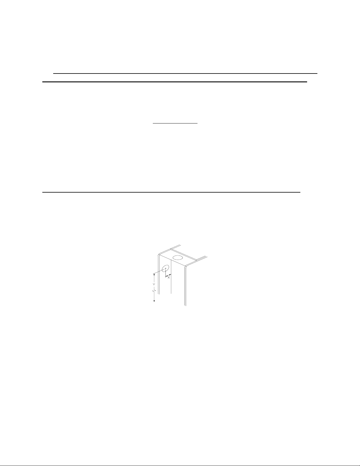
locate the center point for the exit of the flue. Once the center has been located, use a scribe to mark the hole size.
Cut hole and extend flue through side casing.
A trim collar may be ordered from Thermo Products to hide the gap around the flue pipe. This trim collar, however,
is not required for operation. Trim collar/gasket part numbers(s) 14121 / 330073.
TABLE 1: Suggested size and position of flue pipe opening on left hand side of casing.
TRIM COLLAR/
UNIT DIA. HOLE “X” DIM. “Y” DIM. FLUE DIA. GASKET PART #
OH5-85DXE 6-1/2” 4-3/4” 33-1/16” 6” 14131/330005
* FRONT FLUE MODELS ONLY
“X” DIMENSION IS MEASURED FROM SEPARATOR PANEL.
“Y” DIMENSION IS MEASURED FROM THE BLOWER PAN ON “H” MODELS AND FROM THE BASE
ON “L” AND “C” MODELS.
Then, by following the dimensions listed below,
Fig 1: Recommended location for drilling hole to connect
vent pipe to the furnace through the left hand side casing.
NOTE: ROTATION OF FLUE PIPE IS ONLY ALLOWED FOR LEFT HAND SIDE VENTING
APPLICATIONS.
The OH5-85DXE*** may be vented through a standard correctly sized chimney.
B. DRAFT REGULATORS:
A draft regulator is supplied with the furnace and should be installed according to the regulator manufacturers
recommendations. With the burner operating, use a draft gauge to adjust the regulator to the proper setting. (refer to
the instructions enclosed with draft regulator to adjust to the proper setting). When the burner air supply and draft
are properly adjusted, the overfire draft should be a negative (-).01" to (-).02" WC
overfire air tap (See Fig. 8). This tap is provided in the upper burner mounting plate. To measure the flue draft,
punch a small hole in the vent connector pipe as close to the furnace as possible and always before the draft
regulator.
2
1
, as measured at the 5/16"
All installations and services must be performed by qualified service personnel.
C. DUCT WORK/AIR CONDITIONING:
If the furnace is used in connection with summer air conditioning (cooling), the furnace should be installed parallel
with or on the upstream side of the evaporator coil to avoid condensation in the furnace heat exchanger. If the
cooling unit is installed with a parallel flow arrangement, dampers or other means used to control flow of air should
be provided to prevent chilled air from entering the furnace. If such a damper is manually operated, it must be
equipped with a means to prevent operation of either unit, unless the damper is in the full heat or cool position.
The duct system should again follow the current design standard of Air Conditioning Contractors of America
(ACCA) or ASHRAE Fundamentals
Fig. 2.
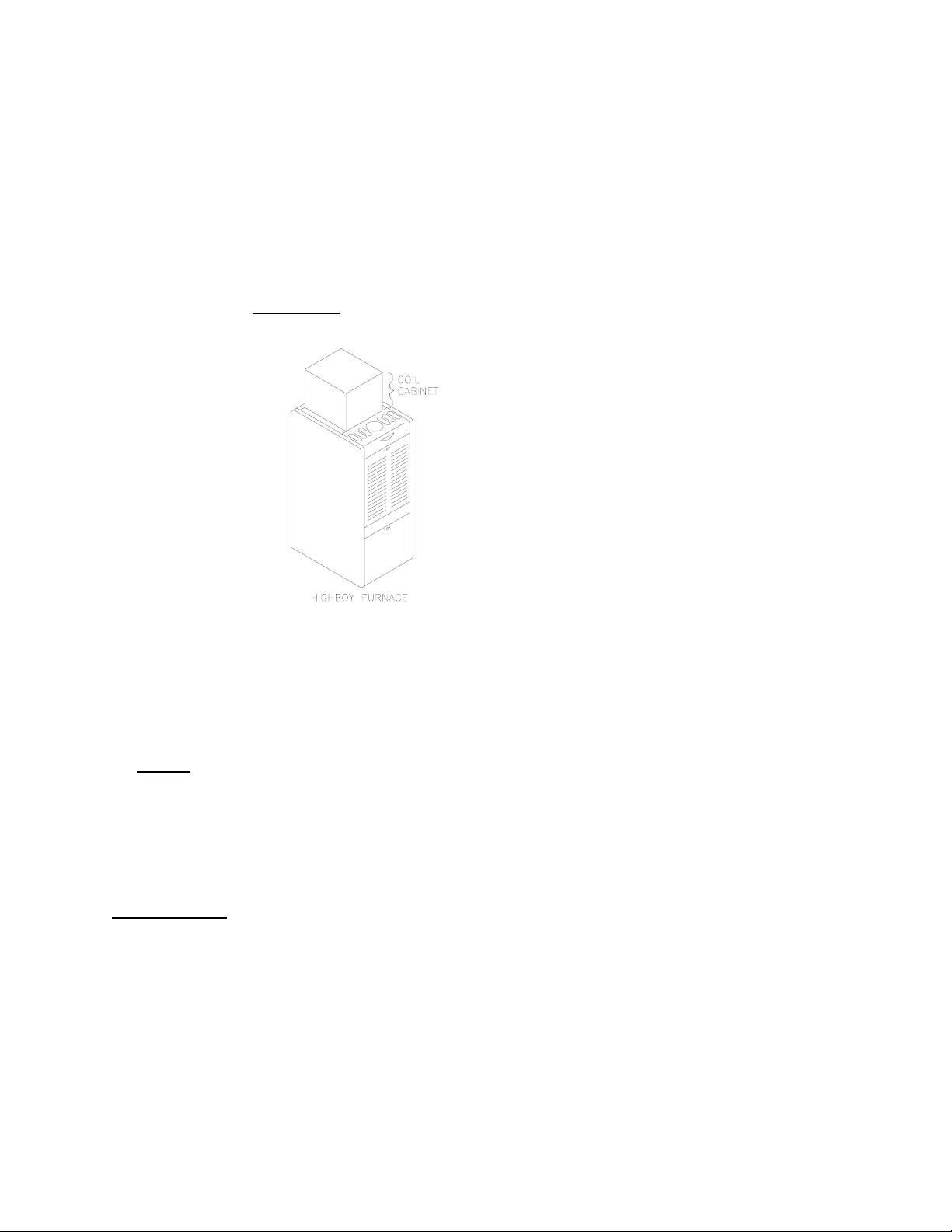
volume.The most common location for the A-shaped coil (A style) is shown in
Fig 2: Acceptable locations for the air conditioner evaporator coil.
NOTICE: The minimum coil pan clearance for a sectional or drum type heat exchanger is three inches unless
specified otherwise by the individual coil manufacturer.
D. FILTERS MOUNTED EXTERNAL TO FURNACE
On highboy
needs of the specific installation.
The filter rack provided with the furnace, refer to Fig. 5, will serve as a template to scribe a mark for the return air
opening on the casing. Place the filter rack on a side casing approximately one inch up from the bottom of the
furnace and centered from side to side. Place the securing flange against the casing when locating the return air
opening. For your convenience, (4) locator knock-outs have been placed at the proper locations on both the left and
right side casings.
PLEASE NOTE:
temporary means.
Position the open end of the filter rack so as to provide access for filter replacement. Once the filter rack is
positioned correctly, scribe a line along the inside of the securing flange on three of the sides. To scribe a line on the
fourth side (the open end), use the open end support as a guide.
Remove the filter rack and cut the return air opening in the casing. Now the filter rack can be anchored to the
furnace with screws or pop-rivets through the securing flange of the filter rack.
furnaces, it is necessary to cut the return air opening in the side or rear casing, depending upon the
While scribing the return air opening, the filter rack can be held in position by tape or similar
3
 Loading...