

Page 1
OIL FURNACE
GENERAL SERVICE AND MAINTENANCE MANUAL
FOR USE WITH THERMO PRIDE OIL FURNACES
THERMO PRODUCTS, LLC.
PO BOX 217
NORTH JUDSON, IN 46366
PHONE: (574) 896-2133
MO-425
ECN 4392-MA
Page 2

All installations and services must be performed by qualified service personnel.
TABLE OF CONTENTS
SECTION BEGINNING PAGE
I. GENERAL INSTRUCTIONS 1
II. INSTALLATION 2
A. CHIMNEY 2
1. PROPER CHIMNEY SIZE 2
2. PREVENTION OF CHIMNEY CONDENSING 3
3. PROPER CHIMNEY HEIGHT 4
4. PROPER VENT CONNECTOR PIPE/CHIMNEY CONNECTION 4
5. PROPER CHIMNEY BOTTOM LEVEL 5
6. TIGHT JOINTS 5
7. TIGHT CLEAN-OUT DOORS AND CONNECTIONS 5
8. NO INTERCONNECTED CHIMNEY FLUES 5
B. FLUE PIPE CLEARANCES, SIZING AND TYPE 5
C. DUCT WORK 7
D. OIL TANK AND PIPING 9
E. OIL FILTER 9
F. WIRING 9
G. INITIAL BURNER OPERATION 11
III. DEALER MAINTENANCE 12
A. TROUBLE SHOOTING 12
B. CAD CELL CHECKOUT PROCEDURE 17
C. CLEANING OR REPLACING FLUE PIPES 17
D. EXTENDED SHUT DOWN AND RESTART 17
i
Page 3
All installations and services must be performed by qualified service personnel.
I. GENERAL INSTRUCTIONS - READ BEFORE START OF INSTALLATION
1. The heating output capacity of the furnace proposed for installation should be based on a heat loss calculation made
according to the manuals provided by the Air Conditioning Contractors of America (ACCA) or the American Society of
Heating, Refrigeration and Air Conditioning Engineers, Inc. (ASHRAE).
2. All local codes and/or regulations take precedence over the instructions in this manual and should be followed accordingly.
In the absence of local codes, installation must conform with these instructions and regulations of the National Fire Protection
Association, and to the provisions of the National Electrical Code
3. The installed furnace must be level and positioned in a central location with respect to outlet registers. It should be located
near the chimney to minimize any horizontal run of flue pipe, which may be required.
4. A furnace installed in a residential garage must be installed so the burner and ignition source are located higher than 18
inches above the floor, unless the required combustion air is taken from the exterior of the garage. Also, the furnace must be
located or protected to avoid physical damage by vehicles.
(ANSI/NFPA 70-1999, or latest edition).
????WARNING: This furnace is not to be used as a construction heater.
5. Listed below are definitions of "COMBUSTIBLE MATERIAL" and "NON-COMBUSTIBLE MATERIAL."
COMBUSTIBLE MATERIAL:
Material made of or surfaced with wood, compressed paper, plant fibers, plastics, or other material that will ignite and burn,
whether flame resistant or not.
NON-COMBUSTIBLE MATERIAL:
Material that is not capable of being ignited and burned. Such materials consist entirely of, or a combination of, steel, iron,
brick, tile, concrete, slate, or glass.
6. The area in which the furnace is located must have as adequate supply of air for combustion and draft control operation.
Open, non-partitioned basements, below grade utility rooms without storm windows, or rooms with loose access doors will
generally permit adequate air infiltration. However, if the furnace is located in an area of the building with tightly fitting doors
and windows, two openings into another room are recommended (each opening having a free area of 1 square inches per 1,000
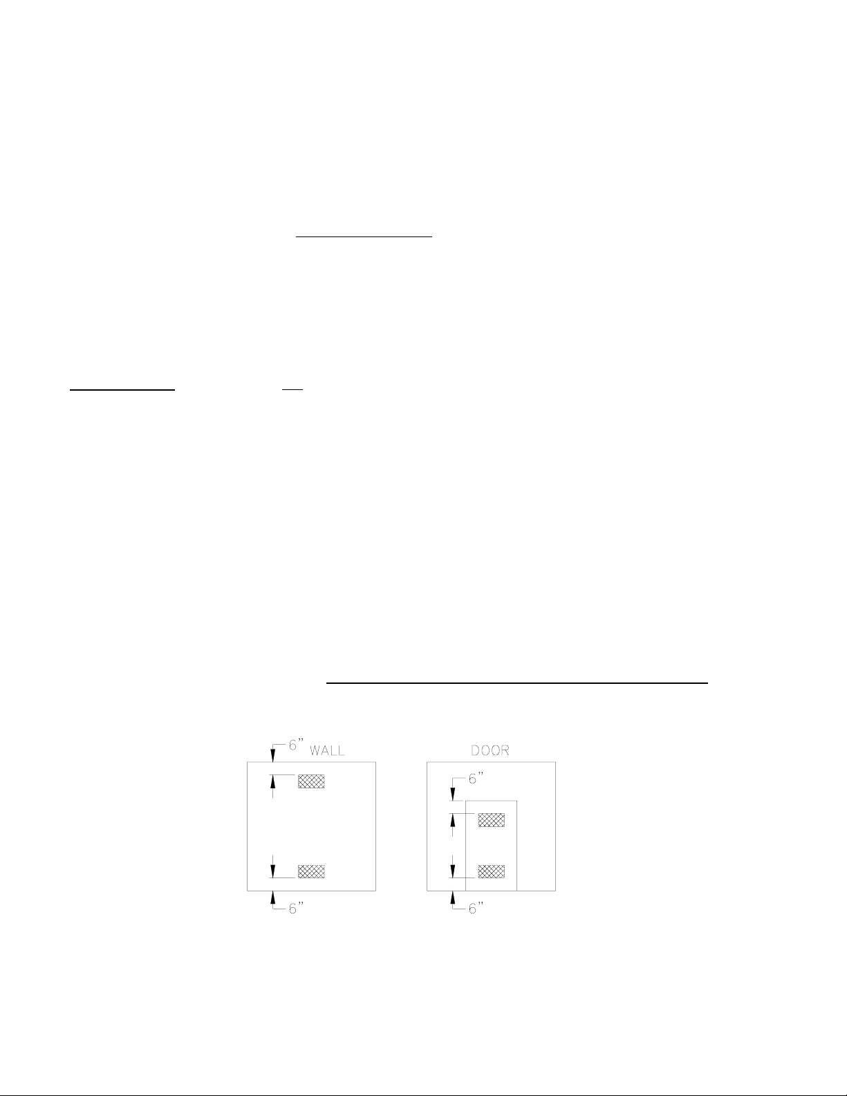
BTUH input of the total input of all appliances located in the room). If these openings are in a wall, they must be at least 6
inches from the ceiling and floor (Fig. 1A) or if they are in a door, they must be at least 6 inches from the top of the door and 6
inches from the bottom of the door. (Fig. 1B). THESE OPENINGS MUST BE FREE AND UNOBSTRUCTED.
EXAMPLE: 100,000 BTUH input furnace requires "two" openings of 100 square inches each.
(Fig. 1A) (Fig. 1B)
Fig 1: Properly Positioned Combustion Air Openings In Walls (Fig. 1A) and Doors (Fig. 1B).
1
Page 4

All installations and services must be performed by qualified service personnel.
If the "entire" building is unusually tightly constructed and/or has an exhaust fan installed, a low pressure zone could be created
within the structure. Air for combustion and draft control operation must be supplied from the outdoors or from spaces freely
communicating with the outdoors. Under these conditions, a permanent opening or openings having total free area of not less
than 1 square inch per 5,000 BTUH of the total input rating of all the appliances located in the same proximity of the furnace
should be provided. These openings must remain free and unobstructed.
Example: 100,000 BTUH input furnace plus a 40,000 BTUH input water heater require an opening or openings totaling 28
square inches of free area.
MAKE-UP AIR:
Today's emphasis on home insulation increases the probability of inadequate air supply to the furnace. Heavy insulation cuts off
infiltration of outside air, which previously replaced inside air removed by bathroom, kitchen and laundry vent fans, and air
escaping up chimneys. This causes a negative pressure differential within the home that reduces the supply of air available to
the furnace for combustion and ventilation.
The Thermo Pride Make-Up-Air Control, installs quickly and easily on any warm air heating system, delivers controlled, fresh
air automatically during the winter and a constant supply of clean, fresh air for comfortable summer living. It resolves the
negative pressure differential problem.
II. INSTALLATION
A. CHIMNEY:
The furnace must be connected to an adequate chimney or an approved vent in accordance with these instructions. An adequate
chimney is one that is sealed and lined with the capability of producing a (-).04" WC flue draft and having the capacity to
handle the amount of stack gases that are introduced into it. A chimney with an internal construction of corrosion resistant tile,
stainless steel, or some other material that will withstand flue gas temperatures up to 900
Qualified service personnel must perform all installations and services.
The following are common chimney requirements necessary for the furnace to operate correctly:
A masonry chimney serving a Thermo Pride oil fired furnace must
Fireplaces, Vents, and Solid Fuel Burning Appliances (NFPA211-1996 or latest edition).
1. PROPER CHIMNEY SIZE:
The inside area of the chimney liner
EXAMPLE: F x r2 = Area of Pipe (sq. in.)
r = radius of pipe
F = 3.1417
Flue Pipe Diameter = 6" [Radius of pipe = ½ diameter of pipe = ½ (6 in.) = 3in.]
F x 32 = 28 sq. in.
NOTE: This formula calculates the minimum
connected to the chimney, the minimum inside area of the chimney should be equal to the area of the largest vent pipe plus one
half the area of any additional vent pipes. If the chimney is too large or condensation has been a problem in the past refer to the
NFPA Standard for the Installation of Oil Burning Equipment
sizing.
should equal, at minimum, the area of the vent pipe exiting the furnace-
inside area of the chimney. If more than one appliance vent connector pipe is
comply with local codes and NFPA Standard for Chimneys,
(NFPA31-1997 or latest edition) Appendix E for proper liner
°F is required.
2
Page 5

All installations and services must be performed by qualified service personnel.
2. PREVENTION OF CHIMNEY CONDENSING:
Stack gas may do one of two things as it escapes up the chimney:
A. Remain entirely in a gaseous state if the internal chimney wall temperature is above the dew point, or
B. Condense water vapor on the chimney walls if they are chilled below the dew point.
Condensing will always occur on chimney walls whose temperatures are below the dew point, but the condensate may
evaporate when the walls warm above the dew point. If the chimney wall temperature does not exceed the dew point during the
heating cycle of the furnace, the moisture may accumulate in large enough quantities to cause problems such as corrosion of a
metal chimney (especially plain steel or galvanized steel), erosion and break up of a tile liner in a masonry chimney and, in
severe cases, corrosion of the heat exchanger. Condensate also could enter the home through cracks or joints in the chimney in
a worse case situation.
Condensation most likely will not occur at the bottom of the chimney because the stack gas heats the chimney walls as it rises
and the bottom will be heated first. This heating of the walls will cause the stack gas temperature to drop, which in turn may
reduce the stack gas temperature below dew point, causing condensation to appear on the upper part of the chimney first. This
condensation may then run down inside the chimney and drip back as far as the flue pipe and heat exchanger, where corrosion
may occur, if not treated.
To prevent condensation, it is necessary that the internal chimney wall temperature always be kept above the dew point. If the
chimney is a masonry type, it may have to be fitted with a flue liner, when the temperature loss is too great for the furnace. If
the chimney is a metal type, then an "all fuel" chimney must be used, such as a Class "A" triple wall or insulated metal chimney.
A liner will act as an insulator and reduce the stack gas temperature loss. Insulation may be added around the liner for further
temperature stability. If the chimney is on the home's exterior or passes through a sizable, unheated area of the building, such as
a porch, high ceiling attic, etc., and condensing occurs, the chimney must be insulated around its exterior to help the flue hold
its temperature. Also, check to see if the chimney is too large for the furnace and other appliances connected to it. If so, reduce
to proper size (see Appendix E of NFPA31) by lining. Be sure to use stainless steel liners, such as stainless types 430, 304, or
for the toughest corrosion problems, type 316. If the chimney is the correct size for the unit and condensing still occurs, then
insulating the vent connector and/or reducing the efficiency of the furnace may have to be done to raise the chimney
temperature.
More detailed information may be obtained from the latest edition of the ASHRAE HVAC Systems and Equipment Handbook
Should the previous recommendations and the information obtained from the ASHRAE Handbook fail to resolve a
condensation problem, another alternative to consider is power side wall venting. For more information, contact your Thermo
Pride representative or contact Thermo Products, LLC. at the address or phone number shown on the cover of this manual.
.
3
Page 6
All installations and services must be performed by qualified service personnel.
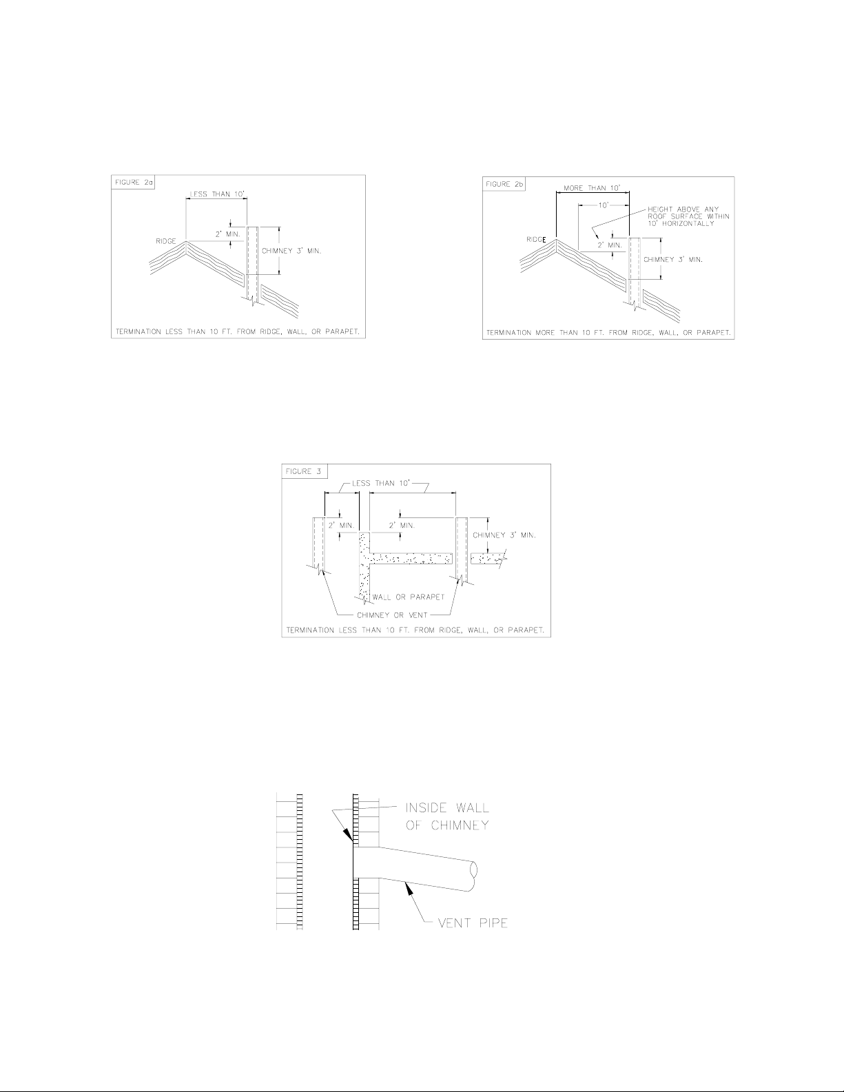
3. PROPER CHIMNEY HEIGHT:
The chimney shall terminate at least 3 feet above the highest point where it passes through the roof of a building and at least 2
feet higher than any portion of a building within a horizontal distance of 10 feet. (See Fig. 2a).
Fig. 2: Proper chimney termination height for pitched roofs
If the chimney penetrates a roof more than 10 feet from a ridge, wall or parapet, a minimum of 3 feet above roof or exit point
must be maintained. See Figure 2b.
If the roof is flat rather than the normal residential pitched roof, refer to Figure 3 for proper clearances.
Fig. 3: Proper chimney termination height for flat roofs
4. PROPER VENT CONNECTOR PIPE/CHIMNEY CONNECTION:
The vent connector pipe should extend only to (and not beyond) the inside wall of the chimney (See Fig. 4). A thimble should
be used to connect the vent connector pipe to the chimney so that the vent connector pipe may be readily removed in case of
inspection or replacement.
Fig. 4: Proper insertion of the vent connector in the chimney.
4
Page 7

All installations and services must be performed by qualified service personnel.
5. PROPER CHIMNEY BOTTOM LEVEL:
In cases where the chimney extends to the basement floor, the draft can usually be improved by filling the base of the chimney
with sand to within 12 inches of the vent connector pipe after relocating the clean-out door. (See Fig. 5).
Fig. 5: Suggested method to improve chimney draft.
6. TIGHT JOINTS:
All joints of the chimney must be tightly sealed. The inside of the chimney should be free of any obstructions, such as loose
brick, broken pieces of tile, or corroded metal.
7. TIGHT CLEAN-OUT DOORS AND CONNECTIONS:
All chimney clean-out doors and flue connections must fit tightly so they will seal to avoid air leaks.
8. NO INTERCONNECTED CHIMNEY FLUES:
If chimney flues are divided or there are multiple flues within one chimney, make sure there are no openings in the partition
separating the divided or individual flues.
B. FLUE PIPE CLEARANCES, SIZING AND TYPE:
The vent connector pipe must not pass through a combustible wall or partition unless adequate protection is provided at the
passageway. An acceptable passageway could be either an approved, ventilated metal thimble which is at least 12 inches larger
in diameter than the vent connector pipe, or brick work which is at least 8 inches thick constructed into the wall and
surrounding the vent connector pipe. (See Fig. 6).
Fig. 6: Suggested method to accommodate vent connector passage through a wall composed of a combustible material.
5
Page 8

All installations and services must be performed by qualified service personnel.
Fig. 7: Alternate constructions that allow reduced clearances to combustible materials.
REDUCTION OF CLEARANCES WITH SPECIFIED FORMS OF PROTECTION
Type of protection applied to and covering all surfaces of combustible material within the distance specified as the required
clearance with no protection unless otherwise noted, all dimensions in inches, refer to Fig. 7.
Required clearance with no protection from the
appliance or chimney connector is:
a. 3-1/2" thick masonry wall without ventilation
air space….
b. 1/2" insulation board over 1" glass fiber or
mineral wool batts…
c. 0.024(24 gauge) sheet metal over 1" glass
fiber or mineral wool batts reinforced with wire
on rear face with ventilated air space…
d. 3- 1/2" thick masonry wall with ventilation air
space..
e. 0.024 (24 gauge) sheet metal with ventilated
air space.
f. 1/2" thick insulation board with ventilation air
space..
g. 0.024 ( 24 gauge) sheet metal with ventilated
air space over 0.024 (24 gauge) sheet metal with
ventilated air space….
h. 1" glass fiber or mineral wool batts
sandwiched between two sheets 0.024 (24 gauge)
sheet metal with ventilated air space
18 inches 9 inches 6 inches
Sides & Sides & Sides &
Above Rear Above Rear Rear
-- 12 -- 6 -- 5
12 9 6 5 4 3
9 6 5 3 3 3
-- 6 -- 6 -- 6
9 6 5 3 3 2
9 6 5 3 3 3
9 6 5 3 3 3
9 6 5 3 3 3
A. Equal the required clearance with no protection.
B. Equals the reduced clearance permitted in accordance with the preceding clearance chart.
C. The protection applied to the construction that covers the combustible material should extend far enough in each
direction to make C equal to A.
6
Page 9

All installations and services must be performed by qualified service personnel.
The vent connector pipe between the furnace and chimney shall be of equal diameter as the flue outlet of the furnace. The vent
connector pipe must be made of 24 gauge (or thicker) corrosion-resistant steel. The vent connector pipe should be as short
as possible and installed so that it has a continuous rise from the furnace to the chimney. The horizontal length of a connector to
a natural draft chimney or vent serving a single appliance shall not be more than 75 percent of the height of the vertical portion
of the chimney or vent above the connector. Elbows should be minimized and the pipe should be joined with metal screws and
supported by straps. All horizontal runs of vent connector pipe should be pitched upward a minimum of 1/4 inch per foot of
run. A thimble should be used to connect the vent connector pipe to the chimney so the pipe may be readily removed in case of
inspection or replacement. See Fig. 6 on preceeding page.
C. DUCT WORK:
The duct system should follow the design standards of Air Conditioning Contractors of America (ACCA) or ASHRAE. The
duct system should be sized for the maximum airflow capabilities of the furnace being installed.
DUCT SIZES FOR HOMES, QUIET OFFICES OR SIMILAR INSTALLATIONS
VELOCITY APPROXIMATELY 800 FEET PER MINUTE
All trunk lines, take-offs, registers and grill free areas must be figured when determining the air handling capacity of a duct
system. By utilizing the previous chart, one can obtain the necessary duct system size. (For example, see Fig. 7). Use a
supplier's catalog for proper sizing of outlet and return air registers to insure that the register will meet the airflow requirements
of the run to which it is connected.
7
Page 10

All installations and services must be performed by qualified service personnel.
Fig. 8: Supply air duct sizing Example
The RETURN AIR DUCT SYSTEM
NOTE: When a return register is located in the same room as the furnace, the register must be at least 20 feet away from the
furnace.
SIZING THE DUCT WORK FOR A COMBINATION HEATING AND COOLING SYSTEM:
Two formulas must be used in determining the CFM requirements of a combustion heating and cooling system.
1. HEATING CFM:
HEAT OUTPUT OF FURNACE (BTUH)
1.1 X TR (TEMPERATURE RISE, °F) = HEATING(CFM)
EXAMPLES:
A. 110,000 BTUH OUTPUT
1.1 X 85°F TR = 1176 CFM FOR HEATING
B. 110,000 BTUH OUTPUT
1.1 X 70°F TR = 1429 CFM FOR HEATING
2. COOLING CFM: 400 CFM X COOLING TONNAGE (12,000 BTUH PER TON)=AIRFLOW FOR
COOLING(CFM)
EXAMPLES:
A. 400 CFM X 3 TON (12,000 BTUH)
1TON
B. 400 CFM X 2.5 TON (12,000 BTUH)
1 TON
IMPORTANT:
SIZE THE DUCT SYSTEM FOR THE LARGER OF THE TWO AIRFLOW REQUIREMENTS
should equal the warm air duct system in airflow capabilities.
= 1,200 CFM FOR COOLING
= 1,000 CFM FOR COOLING
8
Page 11

All installations and services must be performed by qualified service personnel.
D. OIL TANK & PIPING:
????WARNING: All local codes and ordinances take precedence with regard to tank and oil lines. In the
absence of local codes, all tanks and lines must be installed according to NFPA31 Standard for the
Installation of Oil Burning Equipment. All lines must have shutoff valves, a good pipe joint compound
approved for use with oil on all pipe threads, no kinks, no sharp bends, and be properly tested for leaks.
Flare fittings are recommended for tubing. Do not use compression fittings.
Burners are most commonly installed with a single stage fuel pump. This type of fuel pump, when connected with a supply line
only, is satisfactory where the fuel supply is level with, or above the burner thus permitting gravity flow of oil. When it is
necessary to lift oil to the burner, a return line should be connected between the fuel pump and tank. This requires insertion of
the "by-pass" plug into the fuel pump. If the lift exceeds approximately 10 feet, a two-stage pump should be installed with a
return line. When a return line is used with either single or two-stage pumps, air is automatically returned to the tank, making
the unit self-purging.
Use of continuous runs of heavy wall copper tubing is recommended. Always use flare fittings. Avoid use of fittings in
inaccessible locations. Avoid running tubing against any type of heating unit and across ceiling or floor joists.
install the tubing under the floor.
Specific information on piping, fuel pump connections, lift capabilities, and tank installations are provided in the fuel pump
manufacturer's instructions.
Underground tanks should be located outside the building. If the underground tank is less than 275 gallons, the top of the tank
should be below all piping, in order to prevent oil discharge through a broken connection. Underwriter’s Laboratory’s
requirements now stipulate that all 275 gallon and larger tanks have a bottom outlet. This is to prevent the accumulation of
condensate, which causes the tank to rust. It is also recommended to use additives to prevent condensate accumulation, if the oil
supplier does not already use additives.
If the tank is above the burner, and gravity oil feed to the burner is permitted, a single line system may be used. The line should
have a gradual slope downward of approximately 1/2 inch per foot or more to a point directly below where it is connected to the
pump. Sloping the line will help prevent the formation of air pockets.
IMPORTANT:
systems.
E. OIL FILTER:
Use an oil filter with the capacity to filter a 40-50 micron particle for all installations (except the 2-series, which requires a 10
micron particle filter). Install the filter inside the building between the tank shutoff valve and the burner.
Additional information for burner setup is provided in the burner manual that accompanies each burner. The burner
specifications provided in this manual take precedence over specifications provided in the burner manual that accompanies
burner.
The filter cartridge should be replaced at least once a year.
cartridge.
F. WIRING:
All electrical wiring must be installed in strict accordance with local ordinances and codes. In the absence of local ordinances
and codes, all electrical wiring must be in accordance with the National Electrical Code
edition).
An oil safety valve or a delayed action solenoid valve is recommended with all gravity feed oil supply
The filter body should be thoroughly cleaned before installing a new
(ANSI/NFPA 70-1999, or latest
If possible,
9
Page 12

All installations and services must be performed by qualified service personnel.
Below the wiring diagrams for the various Thermo Pride oil furnace models.
10
Page 13

All installations and services must be performed by qualified service personnel.
G. INITIAL BURNER OPERATION:
IMPORTANT: READ BURNER INSTRUCTION MANUAL (INCLUDED WITH BURNER) BEFORE
CONTINUING.
To successfully service and initially set up the oil furnace, you must use the following instruments:
A. A smoke tester
B. A carbon dioxide
C. A flue gas temperature measuring device
D. A draft gauge. Scale should read from (+) .10" WC to (-) .25" WC
E. A volt/OHM/milliamp multimeter
F. An oil pressure gauge capable of reading 0-150 lbs./sq. inch
Turn the main service switch, which provides power to the furnace, to the "OFF" position. Set the thermostat above room
temperature, open all valves in the oil line, and be sure the oil tank is filled. Open the inspection cover on the upper mounting
plate above the burner. Turn on the main service switch, and prime the pump according to the pump manufacturer's
recommendations.
NOTE:
burners) which are 120 PSIG.
Pump pressures for Riello burners range between 145 PSIG and 170 PSIG.
Pump pressures for Beckett burners are 100 PSIG (AF burners) on all units, except the OL2, OC2 and OH2 (AFG
()
CO or oxygen
2
()
O analyzer
2
?CAUTION: DO NOT RUN THE PUMP DRY FOR MORE THAN FIVE MINUTES, AS
IRREPAIRABLE DAMAGE MAY RESULT.
When ignition is established, make a preliminary burner air adjustment to attain a clean combustion flame. Replace the
inspection cover above the burner. After the furnace is warmed up to a steady state condition (about 15 minutes), the final
burner adjustment should be made using combustion instrumentation for measuring draft, smoke, carbon dioxide (CO2) or
oxygen (O2), and stack temperature. In order to achieve the most efficient combustion possible, the following steps must be
taken:
1. DRAFT: Draft readings should be taken both at the overfire air tap and in the flue connection to the chimney.
The overfire draft reading obtained should be a negative (-) .01" to (-) .02" WC and the flue draft reading should be a negative
(-) .02" to (-) .04" WC. The overfire draft reading takes precedence over the flue draft reading when adjusting the barometric
draft control.
2. SMOKE: A smoke sample should be drawn from the same opening used to check the flue draft. If the first flue smoke
reading is "O", close the air shutter on the burner until a trace smoke reading is obtained.
IMPORTANT: TO ACHIEVE PROPER COMBUSTION AND THE EFFICIENCIES LISTED IN SALES
BROCHURES, INSTRUMENTS MUST BE USED TO SECURE CO
3. CARBON DIOXIDE (CO2) OR OXYGEN (O2): Take a CO2 sample from the same location as the smoke sample. It is
possible to achieve readings of up to 14% CO2 or 2% O2, but it is better to have a slightly lower CO2 with a zero smoke
reading. To achieve a lower CO2 reading, open the air shutter on the burner until a zero smoke reading is obtained.
OR O
2
READINGS.
2
11
Page 14

All installations and services must be performed by qualified service personnel.
For example, if a 13% CO2 (3.5% O2) is measured at a trace of smoke, open the air shutter until a zero smoke reading is
obtained with a 12% CO
The reason for recommending the lower CO2 setting even though it may result in slightly lower efficiency is it allows the
burner to better tolerate uncontrollable variables, such as low oil temperatures, dirty oil, low heating content oil, a cold heat
exchanger, and down draft conditions. This operational tolerance means less service and maintenance during heating seasons.
4. FLUE GAS TEMPERATURE: The flue gas temperature will vary to some degree depending on input rate, duct design, and
the airflow across the heat exchanger. The suggested minimum NET stack temperature is 350° F, and the maximum stack
temperature is 500° F. The lower the stack temperature, the higher the efficiency. However, stack temperatures under 350° F
may cause condensation which in turn may lead to metal corrosion.
5. TEMPERATURE RISE: Supply air temperature minus return air temperature. The temperature rise across the furnace
(operating at steady state conditions) should be 70°F. A higher temperature rise will slightly lower the efficiency. A lower
temperature rise may cause condensing. The supply air temperature should be measured in the supply air trunkline
approximately 12 inches down stream of the plenum.
NOTE: Minimum temperature rise is 55°; maximum temperature rise is 85°.
or 4.5% O2.
2
III. DEALER MAINTENANCE
A. TROUBLE SHOOTING:
THIS SECTION IS ONLY TO BE PERFORMED BY TRAINED, QUALIFIED SERVICE PERSONNEL, AND NOT
BY THE FURNACE OWNER.
1. Check for 115VAC line supply voltage to the furnace. If there is no supply voltage, check fuses and service switch.
????CAUTION: When testing electrical equipment, always follow standard electrical procedures.
2. Make sure thermostat is calling for burner operation.
3. Check oil supply and make sure all valves are open.
The troubleshooting chart beginning on the following page should help identify the type of malfunction or deviation from
normal operation. To use this diagram, just follow the instructions in the boxes. If the answer is yes or the condition is true, go
down to the next box. If the answer is no or the condition is false, go to the box on the right. Continue checking and answering
questions and conditions in each box until a problem and/or repair is found. After any maintenance or repair, the trouble
shooting sequence should be repeated until normal system operation is achieved.
12
Page 15

All installations and services must be performed by qualified service personnel.
TURN THERMOSTAT TO CALL FOR HEAT
DOES THERMOSTAT MAKE CONTACT?
IS ROOM TEMPERATURE
BELOW THERMOSTAT SETTING?
Yes
IS THE TRANSFORMER
SUPPLYING 24 VOLTS
TO THE THERMOSTAT
REPLACE THERMOSTAT
Yes
Yes
No
IS ROOM TEMPERATURE
No
ABOVE THERMOSTAT
SETTING?
No
Yes
COOL THE THERMOSTAT
No No
ARE WIRES CONNECTED
PROPERLY
Yes
IS THERE 120VAC
ACROSS THE PRIMARY
SIDE OF THE
TRANSFORMER?
No
Yes
TURN T'STAT SETTING
ABOVE ROOM TEMPERATURE
CORRECT WIRE
CONNECTIONS
CHECK INPUT POWER,
DOOR INTERLOCK,SERVICE
SWITCH AND FUSES
DOES BURNER MOTOR
START?
Yes
No
IS VOLTAGE PRESENT
AT BURNER MOTOR?
Yes
IS MOTOR RESET
BUTTON POPPED OUT
Yes
No
No
REPLACE TRANSFORMER
IS THE PRIMARY RELAY
LOCKED OUT ON SAFETY
Yes
PUSH IN RESET BUTTON
IS THE OIL PUMP
FROZEN UP?
Yes
No
No
CHECK CONTINUITY
OF WIRING
REPLACE BURNER
MOTOR
PUSH IN RESET BUTTON REPLACE OIL PUMP
13
Page 16

All installations and services must be performed by qualified service personnel.
Yes
IS IGNITION ESTABLISHED?
ARE THE ELECTRODES
Yes
No
ARCING?
Yes
IS THE OIL PUMP
OPERATING?
Yes
PERFORM CAD CELL CHECK
OUT ON PAGE 17.
No
IS THE NOZZLE AND
CAD CELL POSITIONED
PROPERLY? *
Yes
IS IGNITION TRANSFORMER
CAPABLE OF PRODUCING A
3/4" ARC? (10,000 VAC)
ARE THE ELECTRODES ALIGNED
CONTACT SPRINGS TOUCHING
ELECTRODE RODS, & PORCELAIN
CLEAN AND UNCRACKED?
IS THE COUPLING BETWEEN
THE BURNER MOTOR AND
THE PUMP STRIPPED?
Yes
REPLACE COUPLER
No
No
No
POSITION THEM PER
BURNER MANUFACTURERS
INSTRUCTIONS
REPLACE IGNITION
TRANSFORMER
REPLACE PUMP
FURNACE OPERATES FOR
COMPLETE CYCLE?
BURNER RUN NORMAL
BLOWER RUNS
NORMAL CYCLE?
No
MEASURE MILLIAMPS BETWEEN 'W' &'R'
No
ON THE T'STAT SUBBASE AND SET HEAT
ANTICIPATOR ACCORDINGLY
CYCLE?
IS HEAT ANTICAPATOR SET
No
TO MILLIAMP SETTING
MEASURED ON SUBBASE?
Yes
Yes
IF PROBLEM PERSISTS CONTINUE TO NEXT SECTION.
No
IS AIR TEMPERATURE RISE
APPROX. 70 DEGREES F?
No
CHECK-BLOWER SPEED
AND RETURN AIR TEMPERATURE
Yes
CHECK FAN ON & OFF SETTINGS
ON FAN & LIMIT CONTROL
* ALSO PERFORM CAD CELL CHECK OUT PROCEDURE(REFER TO INDEX).
14
Page 17

All installations and services must be performed by qualified service personnel.
PROPER COMBUSTION ACHIEVED?
NO
IS THE BURNER AIR TUBE
IS THE PROBLEM DELAYED
IGNITION?
NO
INSERTION 0-'1/4"
BACK FROM INSIDE OF
REFRACTORY?
YES
NO
CORRECT INSERTION OR
AIR TUBE BURNOFF MAY
OCCUR.
IS OVERFIRE DRAFT
- .01 TO - .02 OVERFIRE
YES
IS THE NOZZLE
PLUGGING?
YES
ARE THE ELECTRODES
PROPERLY ALIGNED?
YESYES
IS PUMP PRESSURE SET
ACCORDING TO BURNER
APPLICATION CHART?
YES
NO NO
IS THERMALLY
ACTIVATED VENT
DAMPER PRESENT?
YES
REMOVE OR REPLACE
WITH AUTOMATIC
DAMPER
IS COMBUSTION SET TO
A TRACE OF SMOKE AND
THEN BACKED OFF 1%?
YES
NO
NO
NO
ALIGN ELECTRODES PER
BURNER MANUFACTURERS
SPECIFICATIONS
FOR BECKETT BURNERS,
ADJUST TO 100-120 PSIG
FOR RIELLO 145-170 PSIG
ARE CHIMNEY AND HEAT
EXCHANGER CLEAN?
YES
BRING IN COMBUSTION AIR
FROM ANOTHER ROOM OR
OUTDOORS-INSTALL
INDUCER TO CREATE DRAFT
ADJUST COMBUSTION AIR TO A
TRACE OF SMOKE, THEN TAKE
CO2 OR O2 READING, NEXT
SUBTRACT 1% FROM THE CO2
OR ADD 1% TO O2, THEN
ADJUST AIR ACCORDINGLY.
REPLACE
BURNER
NOZZLE
IS WATER, DIRT, OR
SULGE PRESENT IN
THE SYSTEM?
YES
REPAIR SYSTEM LEAKS
TO PREVENT FUTURE
PROBLEMS AND MIX
IN PROPER ADDITIVES
TO REMOVE WATER
AND SLUDGE
NO
TRY TO RAISE ROOM & OIL
TEMPERATURE.
IF THIS CANNOT BE DONE DO
THE FOLLOWING:
DECREASE NOZZLE SIZE AND
INCREASE PUMP PRESSURE.
CHOOSE SMALLER NOZZLE
SIZE AND PUMP PRESSURE
FROM "EFFECTS OF PRESSURE
ON NOZZLE FLOW RATES" AT
THE END OF THE TROUBLE
SHOOTING SECTION.
15
Page 18

All installations and services must be performed by qualified service personnel.
Yes
DOES FURNACE OPERATE
WITHOUT CONDENSING?
No
IS STACK TEMPERATURE
ABOVE 350 DEGREES F?
Yes
TROUBLE SHOOTING ENDS.
REPEAT PROCEDURE UNTIL TROUBLE FREE OPERATION IS OBTAINED.
Yes
No
HAS THE BURNER
COMBUSTION BEEN
SET AS INDICATED
IN ABOVE SECTION?
GO TO PROPER COMBUSTION
No
Yes
IS THE TEMPERATURE
DIFFERENCE BETWEEN
SUPPLY AND RETURN AIR
70 DEGREES F OR MORE?
No
Yes
-- INCREASE LENGTH OF BURNER ON CYCLE
-- INSULATE CHIMENY WITH CHIMNEY LINER.
ACHIEVED SECTION ABOVE
AND SET COMBUSTION
ADJUST BLOWER SPEED
TO RAISE TEMPERATURE
RISE.
NOZZLE
RATING
AT
100 PSI
.50
.65
.75
.85
.90
1.00
1.10
1.20
1.25
EFFECTS OF PRESSURE ON NOZZLE FLOW RATE
NOZZLE FLOW RATES IN
GALLONS PER HOUR (Approx.)
80PSI 120PSI 140PSI
0.45
0.58
0.67
0.76
0.81
0.89
0.99
1.07
1.12
0.55
0.71
0.82
0.93
0.99
1.10
1.21
1.31
1.37
0.59
0.77
0.89
1.00
1.07
1.18
1.30
1.41
1.48
16
NOZZLE
RATING
AT
100 PSI
1.35
1.50
1.65
1.75
2.00
2.25
2.50
2.75
3.00
NOZZLE FLOW RATES IN
GALLONS PER HOUR (Approx.)
80 PSI 120 PSI 140 PSI
1.21
1.34
1.48
1.57
1.79
2.01
2.21
2.44
2.69
1.48
1.64
1.81
1.92
2.19
2.47
2.74
3.00
3.29
1.60
1.78
1.95
2.07
2.37
2.66
2.96
3.24
3.55
Page 19

All installations and services must be performed by qualified service personnel.
B. CAD CELL CHECKOUT PROCEDURE:
1. Remove cad cell lead wires, then start the burner. Shortly after burner starts, place a temporary jumper between
terminal f - f. Connect ohmmeter across cad cell lead wires - resistance should be under 1600 ohms.
2. Stop burner and remove temporary jumper.
3. With the burner off, check dark cell resistance across cad cell lead wires. Resistance should be greater then 20,000
ohms. If cell resistances are different from above, recheck wiring location of cell, etc. If necessary, replace plug in
portion of cell, (Part No. 350104).
4. Reconnect cad cell lead wires. Check out the Protectorelay control (primary control) according to the instructions
packed with the control.
C. CLEANING OR REPLACING FLUE PIPES:
Flue pipes should be inspected during the annual maintenance check-up or during each subsequent service call.
Flue pipes should be inspected for restrictions due to soot or carbon build-up as well as foreign matter or any
material which may cause the venting system to become restricted and not allow the proper venting of combustion
products. If a restriction occurs, the flue pipe must
Flue pipes should also be inspected for any signs of corrosion, deterioration or leakage that may cause combustion
byproducts to infiltrate the home or indoor environment. If signs of corrosion, deterioration or leakage are evident
then the flue pipe must be replaced with a properly sized agency approved flue pipe.
D. EXTENDED SHUT DOWN AND RESTART: If an oil furnace is shut down or off for an extended period of
time, several steps can be taken to help insure a smooth and reliable restart.
ON SHUT-DOWN:
1. Close oil supply valve.
2. Disconnect power to the unit.
3. Fill oil tank to prevent condensation.
4. If shut down exceeds one season, an oil stabilizer should be added to the oil tank as recommended by your oil
supplier.
ON START-UP:
1. Have system inspected and started by a qualified service person.
2. Check oil level in tank. If tank has not been filled with fresh oil, inspect oil for signs of contamination such as
water, algae, dirt or other impurities.
3. Change oil filter cartridge and clean canister.
4. Set thermostat above room temperature.
5. Open all valves in the oil supply line.
6. Open the inspection cover on upper mounting plate.
7. Turn on the main power or service switch to unit to start the burner. If the burner does not start, immediately
reset the manual overload switch on the motor (if so equipped) and the safety switch of the burner primary
control. Bleed the fuel unit as soon as the burner motor starts rotating. To bleed the fuel unit or pump, attach
a clear plastic hose over the vent plug. Loosen the plug and catch the oil in an empty container. Tighten the
plug when all the air appears to be purged. If the burner stops during bleeding; wait three to five minutes for
the control safety switch to cool then manually reset the switch completing the bleeding procedure.
be cleaned or replaced to ensure proper venting.
17
Page 20

All installations and services must be performed by qualified service personnel.
????CAUTION: Do not attempt to start burner when:
1.Excess oil has accumulated
2.When the furnace or burner is full of vapor
3.When the combustion chamber is very hot.
If one or more of these conditions exist, contact a qualified service personal.
8. Follow "initial burner operation" procedures from section G.
18
 Loading...