

Page 1
ECM OPERATION MANUAL
FOR USE WITH MODELS:
CHX3-75N CDX3-75N
CHX3-100N CDX3-100N
CHX3-125N CDX3-125N
: IF YOU DO NOT FOLLOW THE SAFETY PRECAUTIONS BELOW AND IN THIS MANUAL, A
FIRE OR EXPLOSION MAY RESULT CAUSING PROPERTY DAMAGE, PERSONAL INJURY, OR LOSS OF
LIFE.
DO NOT STORE OR USE GASOLINE OR OTHER FLAMMABLE VAPORS AND LIQUIDS IN THE VICINITY OF
THIS OR ANY OTHER APPLIANCE.
WHAT TO DO IF YOU SMELL GAS:
• DO NOT TRY TO LIGHT ANY APPLIANCE.
• DO NOT TOUCH ANY ELECTRICAL SWITCH; DO NOT USE ANY PHONE IN YOUR BUILDING.
• LEAVE THE BUILDING IMMEDIATELY.
• IMMEDIATELY CALL YOUR GAS SUPPLIER FROM A NEIGHBOR’S PHONE. FOLLOW THE GAS
SUPPLIER’S INSTRUCTIONS.
• IF YOU CANNOT REACH YOUR GAS SUPPLIER; CALL THE FIRE DEPARTMENT.
INSTALLATION AND SERVICE MUST BE PERFORMED BY A QUALIFIED INSTALLER, SERVICE AGENCY OR
THE GAS SUPPLIER. (REFERRED TO IN THESE INSTRUCTIONS AS A QUALIFIED HEATING
CONTRACTOR).
PLEASE READ THESE INSTRUCTIONS PRIOR TO INSTALLATION, INITIAL FIRING, AND BEFORE
PERFORMING ANY SERVICE OR MAINTENANCE. THESE INSTRUCTIONS MUST BE LEFT WITH THE
HOMEOWNER AND SHOULD BE RETAINED FOR FUTURE REFERENCE BY QUALIFIED SERVICE
PERSONNEL.
THERMO PRODUCTS, LLC.
BOX 217
NORTH JUDSON, IN 46366
PHONE: (574) 896-2133
MADE IN USA
MG-1037
ECN 5262-MA 120326
Page 2

All installations and services must be performed by qualified service personnel.
INDEX
SECTION BEGINNING PAGE
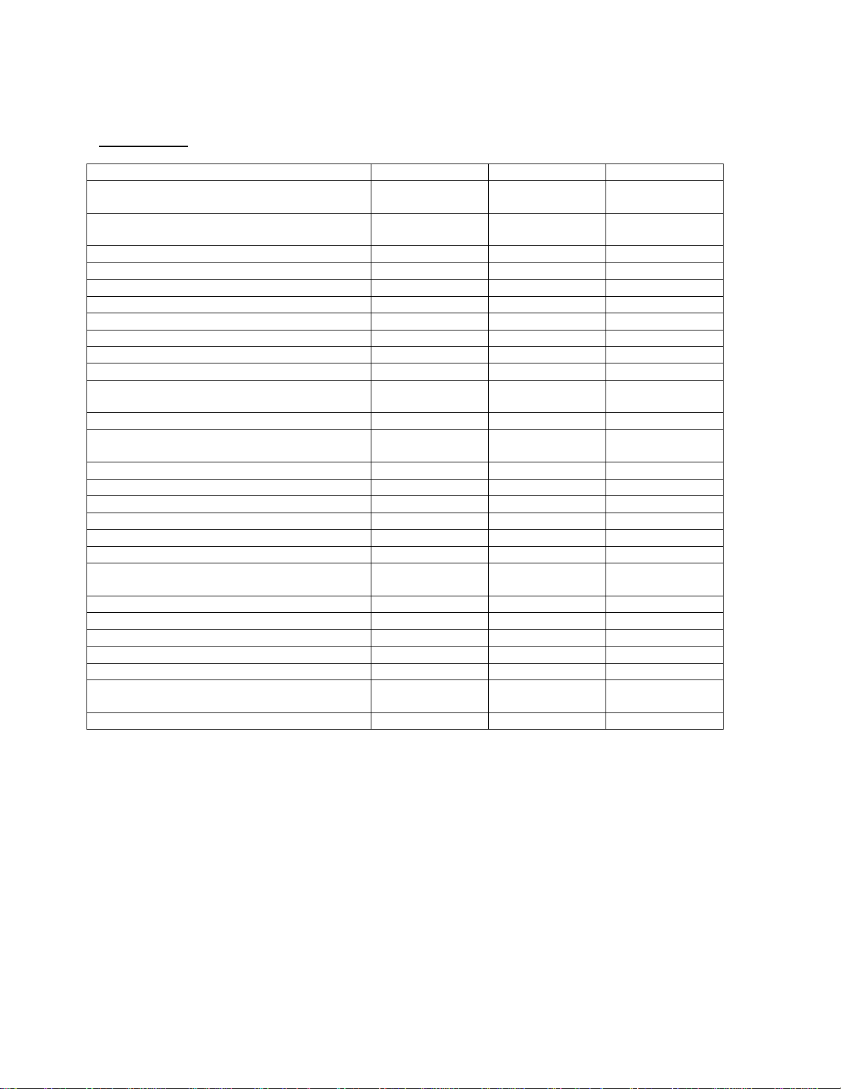
I. FURNACE SPECIFICTIONS (SHIPPED SETTINGS) 1
II. BLOWER INFORMATION 3
A. WIRING 3
B. CFM TABLES 5
III. ECM TROUBLESHOOTING 9
A. GENERAL GUIDELINES TO TROUBLESHOOTING GE ECM 9
B. TROUBLESHOOTING CHARTS 12
i
Page 3
All installations and services must be performed by qualified service personnel.
MODEL NO.
CHX3-75
CHX3-100
CHX3-125
HEAT INPUT RATE IN BTU/ HR
(High fire/ Low fire)
75,000 / 52,000
100,000 / 70,000
125,000 / 87,500
HEATING CAPACITY IN BTU/HR
(High fire/ Low fire)
70,875 / 49,612
94,500 / 66,150
117,500 / 82,250
HEIGHT OF CASING
44-1/4”
44-1/4”
44-1/4”
WIDTH OF CASING
17”
21”
24”
DEPTH OF CASING
27-1/2”
27-1/2”
27-1/2”
WARM AIR OUTLET
15 x 18
19 x 18
22 x 18
RETURN AIR INLET
25 x 16
25 x 16
25 x 16
DIA. OF FLUE
2”
3”
3”
DIA. OF COMBUSTION
AIR INTAKE
FLOWRATE from .2” & .5” w.c.
EXTERNAL STATIC PRESSURE
@COOLING TAP A (CFM)
1000
1200
1400
@COOLING TAP B (CFM)
800
1000
1200
@COOLING TAP C (CFM)
1200
1400
1600
@COOLING TAP D (CFM)
1400
1600
2000
HEATING
HEATING
HEATING
@HEATING TAP A
(CFM @High fire/Low fire)
931 / 760
1243 / 1015
1556 / 1270
TEMPERATURE RISE (° F)
70 / 60
70 / 60
70 / 60
BLOWER MOTOR HP
.5
.75
1
POWER CHOKES
-
2.65 Mh
2.1 Mh
LARGEST RECOMMENDED
AIR CONDITIONER
SIZE OF FILTERS
24-3/4” x 15-3/4”
24-3/4” x 15-3/4”
24-3/4” x 19-3/4”
I. FURNACE SPECIFICATIONS (SHIPPED SETTINGS)
CHX3 SERIES
2” 3” 3”
COOLING COOLING COOLING
NOTES:
1. Heating capacity based on annual fuel utilization efficiency rated by manufacturer.
2. On all outlet and inlet dimensions, the first dimension is width.
3. Electrical characteristics at 115 volts, 60 Hz., 1 phase (less than 15 amps, for all models).
4. All specifications are subject to change without notice.
3.5 Ton 4 Ton 5 Ton
1
Page 4
All installations and services must be performed by qualified service personnel.
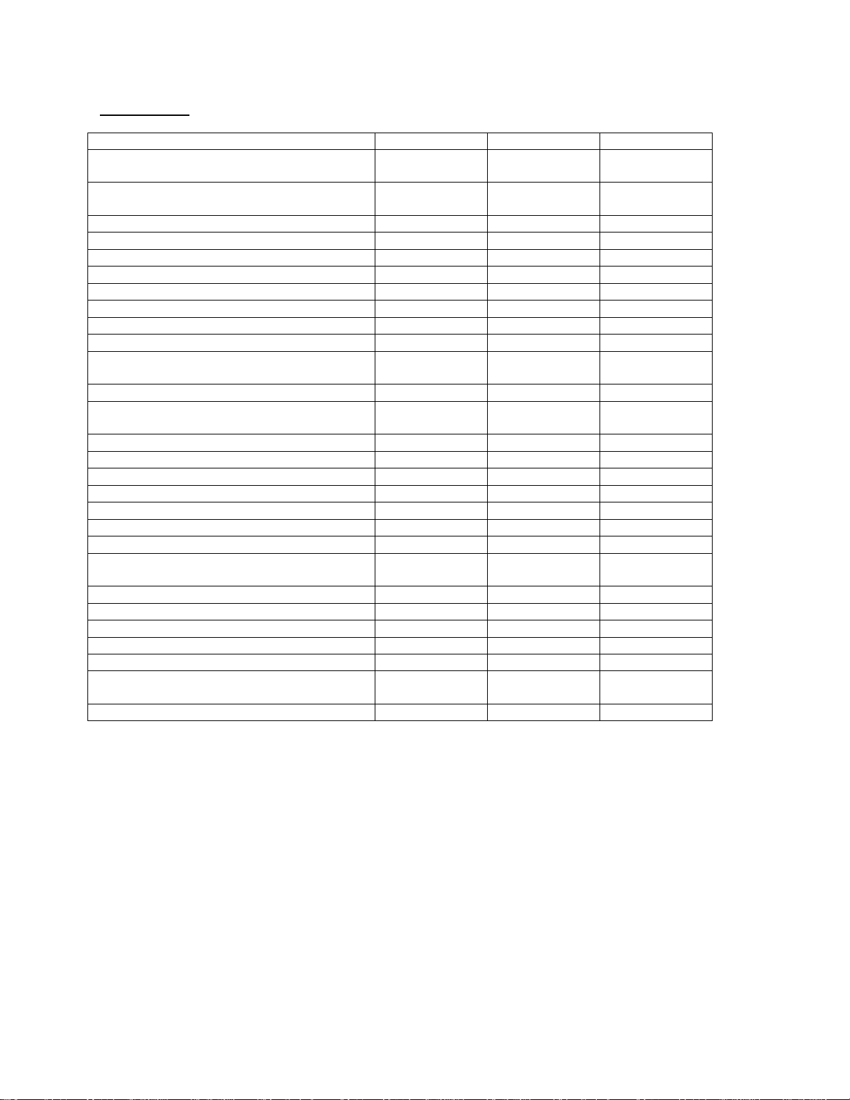
MODEL NO.
CDX3-75
CDX3-100
CDX3-125
HEATING INPUT RATE IN BTU / HR
(High fire / Low fire)
75,000 / 56,250
100,000 / 75,000
125,000 / 93,750
HEATING CAPACITY IN BTU/HR
(High fire / Low fire)
69,750 / 52,312
93,000 / 69,750
116,250 / 87,187
HEIGHT OF CASING
46-1/4”
46-1/4”
46-1/4”
WIDTH OF CASING
17”
21”
24”
DEPTH OF CASING
27-1/2”
27-1/2”
27-1/2”
WARM AIR OUTLET
15 x 18
19 x 18
22 x 18
RETURN AIR INLET
15 x 22
19 x 22
22 x 22
DIA. OF FLUE
2”
3”
3”
DIA. OF COMBUSTION
AIR INTAKE
FLOWRATE from .2” & .5” w.c.
EXTERNAL STATIC PRESSURE
@COOLING TAP A (CFM)
1000
1200
1400
@COOLING TAP B (CFM)
800
1000
1200
@COOLING TAP C (CFM)
1200
1400
1600
@COOLING TAP D (CFM)
1400
1600
2000
HEATING
HEATING
HEATING
@HEATING TAP C
(CFM @ High fire / Low fire)
1012 / 826
1340 / 1094
1673 / 1366
TEMPERATURE RISE (° F)
65 / 60
65 / 60
65 / 60
BLOWER MOTOR HP
.5
.75
1
POWER CHOKES
-
2.65Mh
2.1Mh
LARGEST RECOMMENDED
AIR CONDITIONER
SIZE OF FILTERS
21-3/4” x 14”(2)
21-3/4” x 14”(2)
21-3/4” x 14”(2)
CDX3 SERIES
2” 3” 3”
COOLING COOLING COOLING
NOTES:
1. Heating capacity based on annual fuel utilization efficiency rated by manufacturer.
2. On all outlet and inlet dimensions, the first dimension is width.
3. Electrical characteristics at 115 volts, 60 Hz., 1 phase (less than 15 amps. for all models).
4. All specifications are subject to change without notice.
3.5 Ton 4 Ton 5 Ton
2
Page 5
All installations and services must be performed by qualified service personnel.
II. BLOWER INFORMATION
A. WIRING
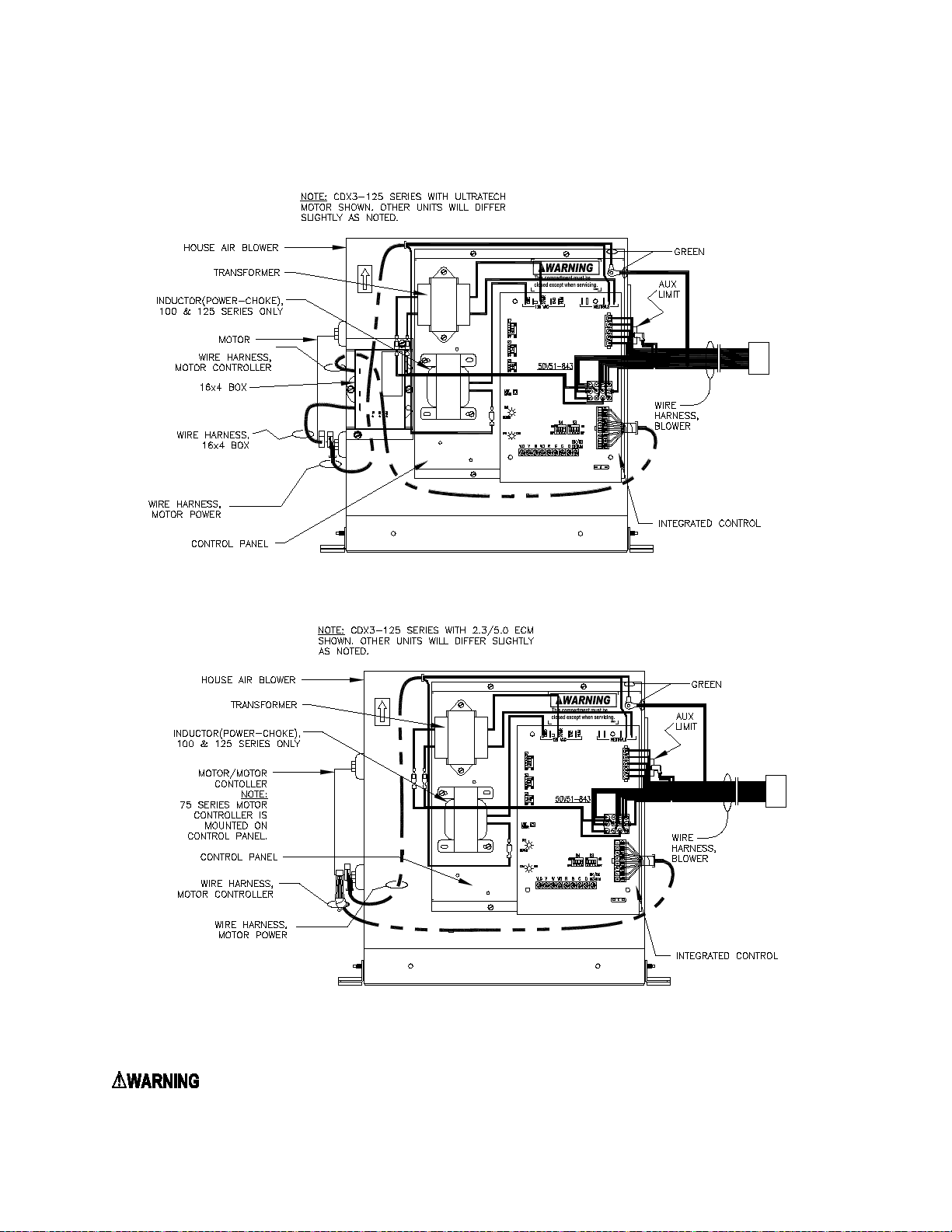
Figure 1: BLOWER WIRING
: TURN OFF THE ELECTRICAL POWER to the furnace before atte mpting to disconnect blowe r
wiring.
3
Page 6

All installations and services must be performed by qualified service personnel.
S2 DIP Switch
Switch Settings
S2-1
S2-2
S2-3
Off
On
Off
S5 DIP Switch
Switch Settings
All Furnace
S5-1
Off *
On
S5-2
Dehumidistat
Off
Installed
On
Not Installed *
* Factory Setting
S7 DIP Switch
Switch Settings
Options
S7-1
S7-2
Time
Off
Off
Off *
On
Off
10 Min
Off
On
Auto
On
On
20 Min
S7-3
S7-4
Time
Off
Off
90 Sec
Off
On
120 Sec *
On
Off
150 Sec
On
On
180 Sec
* Factory Setting / 2 Stage Thermostat setting
Option DIP Switch settings:
All Furnace Models
Models
De-
humidifier
Thermostat Type
and W2 Delay
Heat Fan Off Delay
For S3 and S4 DIP switches refer to CFM tables in the following section.
4
Page 7

All installations and services must be performed by qualified service personnel.
0.2 0.5 0.2 0.5
S4-3 OFF
S4-4 OFF
S4-3 ON
S4-4 OFF
S4-3 OFF
S4-4 ON
S4-3 ON
S4-4 ON
0.2 0.5 0.2 0.5
S4-3 OFF
S4-4 OFF
S4-3 ON
S4-4 OFF
S4-3 OFF
S4-4 ON
S4-3 ON
S4-4 ON
0.2 0.5 0.2 0.5
S4-3 OFF
S4-4 OFF
S4-3 ON
S4-4 OFF
S4-3 OFF
S4-4 ON
S4-3 ON
S4-4 ON
CHX3-125
settings
CFM
Rise (oF)
Static Pressure (Amps /
CFM
Rise (oF)
Static Pressure (Amps /
CHX3-100
settings
CFM
Rise (oF)
Static Pressure (Amps /
CFM
Rise (
F)
Static Pressure (Amps /
CHX3-75
settings
CFM
Rise (oF)
Static Pressure (Amps /
CFM
Rise (oF)
Static Pressure (Amps /
B. CFM TABLES
The following tables contain blower speed settings and their respective airflow rates for the ECM blower motor. To
change airflow rates from that of the shipped settings, use the respective S3 and S4 dip switches on the furnace’s
integrated control board (see Figure 1).
S4 DIP SWITCH - HEA TING SPEED SELECTIONS
Dip sw itch
Dip sw itch
Low fire
760 60 1.4 / 109 2.1 / 175 931 70 2.0 / 163 2.8 / 239
708 65 1.2 / 95 1.9 / 154 867 75 1.7 / 138 2.4 / 205
826 55 1.7 / 132 2.3 / 195 1012 65 2.3 / 197 3.1 / 269
909 50 1.9 / 155 2.7 / 227 1114 59 2.8 / 238 3.3 / 289
Low fire
1015 60 1.8 / 151 2.7 / 230 1243 70 2.6 / 221 3.6 / 314
947 64 1.7 / 136 2.4 / 206 1160 75 2.3 / 192 3.2 / 278
1094 56 2.1 / 180 3.0 / 258 1340 65 2.1 / 269 4.2 / 374
1184 51 2.4 / 209 3.4 / 299 1450 60 3.7 / 327 4.7 / 428
Watts)
Watts)
High Fire
High Fire
o
Watts)
Watts)
NOTE: Electrical data provided for Ultratech motor
Dip sw itch
Low fire
1270 60 2.9 / 247 3.8 / 343 1556 70 4.5 / 406 5.5 / 508
1185 64 2.5 / 218 3.4 / 300 1452 75 3.9 / 354 4.7 / 436
1366 56 3.4 / 294 4.4 / 385 1673 65 5.3 / 481 6.3 / 581
1480 51 3.9 / 354 4.9 / 431 1813 60 6.3 / 580 7.5 / 693
=FACTORY SETTING
Watts)
High Fire
Watts)
5
Page 8

All installations and services must be performed by qualified service personnel.
0.2 0.5 0.2 0.5
S4-3 OFF
S4-4 OF F
760 64 1.3 / 104 2.1 / 170 931 70 1.7 / 136 2.6 / 212
S4-3 ON
S4-4 OF F
708 69 1.1 / 90 1.9 / 155 867 75 1.5 / 120 2.3 / 197
S4-3 OFF
S4-4 ON
826 59 1.4 / 116 2.3 / 197 1012 65 1.9 / 160 2.7 / 231
S4-3 ON
S4-4 ON
909 54 1.6 / 128 2.5 / 215 1114 59 2.2 / 190 3.1 / 268
0.2 0.5 0.2 0.5
S4-3 OFF
S4-4 OF F
1015 64 1.5 / 123 2.3 / 182 1243 70 1.8 / 145 2.8 / 242
S4-3 ON
S4-4 OF F
947 69 1.3 / 102 2.1 / 176 1160 75 1.6 / 130 2.5 / 218
S4-3 OFF
S4-4 ON
1094 60 1.6 / 130 2.5 / 210 1340 65 2.0 / 171 3.0 / 262
S4-3 ON
S4-4 ON
1184 55 1.9 / 155 2.8 / 235 1450 60 2.7 / 231 3.8 / 335
0.2 0.5 0.2 0.5
S4-3 OFF
S4-4 OF F
1270 64 2.5 / 205 3.4 / 288 1556 70 3.7 / 320 4.7 / 415
S4-3 ON
S4-4 OF F
1185 69 2.2 / 181 3.0 / 250 1452 75 3.4 / 285 4.1 / 365
S4-3 OFF
S4-4 ON
1366 60 2.9 / 250 3.8 / 330 1673 65 4.4 / 388 5.4 / 488
S4-3 ON
S4-4 ON
1480 55 3.4 / 290 4.2 / 370 1813 60 5.3 / 472 6.4 / 575
=FACTORY SETTING
Rise (oF)
CDX3-75
CDX3-100
CDX3-125
Static Pressure
(Amp s / Watts)
Dip
switch
settings
Low fire
CFM
Rise (oF)
High Fire
CFM
Static Pressure
(Amp s / Watts)
Dip
switch
settings
Low fire
CFM
Rise (oF)
High Fire
CFM
Rise (oF)
Static Pressure
(Amp s / Watts)
Static Pressure
(Amp s / Watts)
Dip
switch
settings
Low fire
CFM
Rise (oF)
High Fire
CFM
Rise (oF)
Static Pressure
(Amp s / Watts)
Static Pressure
(Amp s / Watts)
NOTE: Electrical data pr ovided for Ultratech motor
6
Page 9

All installations and services must be performed by qualified service personnel.
CHX3-75
TONS CFM/TON S3-1 S3-2 S3-3 S3-4
0.2 0.5
440 0N OFF ON OFF 880 1.8 / 146 2.4 / 206 750 580 490
400 ON OFF OFF OFF 800 1.5 / 121 2.3 / 188 680 530 450
360 ON OFF OFF ON 720 1.3 / 104 2.0 / 160 610 480 400
440 OFF OFF ON OFF 1100 2.6 / 223 3.5 / 304 940 730 620
400 OFF OFF OFF OFF 1000 2.3 / 193 3.0 / 262 850 660 560
360 OFF OFF OFF ON 900 1.8 / 150 2.6 / 218 770 590 500
440 OFF ON ON OFF 1320 3.9 / 343 4.8 / 441 1120 870 740
400 OFF ON OFF OFF 1200 3.2 / 275 4.0 / 355 1020 790 670
360 OFF ON OFF ON 1080 2.5 / 213 3.4 / 295 920 710 610
440 ON ON ON OFF 1540 5.6 / 508 5.7 / 519 1310 1020 860
400 ON ON OFF OFF 1400 4.4 / 393 5.5 / 494 1190 920 790
360 ON ON OFF ON 1260 3.5 / 310 4.6 / 408 1070 830 710
CHX3-100
TONS CFM/TON S3-1 S3-2 S3-3 S3-4
0.2 0.5
440 0N OFF ON OFF 1100 2.0 / 165 2.9 / 250 940 730 620
400 ON OFF OFF OFF 1000 1.8 / 148 2.5 / 217 850 660 560
360 ON OFF OFF ON 900 1.5 / 119 2.3 / 191 770 590 500
440 OFF OFF ON OFF 1320 3.0 / 263 3.9 / 351 1120 870 740
400 OFF OFF OFF OFF 1200 2.4 / 202 3.4 / 294 1020 790 670
360 OFF OFF OFF ON 1080 2.0 / 161 2.8 / 242 920 710 610
440 OFF ON ON OFF 1540 4.0 / 362 5.1 / 470 1310 1020 860
400 OFF ON OFF OFF 1400 3.1 / 274 4.3 / 387 1190 920 790
360 OFF ON OFF ON 1260 2.6 / 220 3.6 / 319 1070 830 710
440 ON ON ON OFF 1760 5.4 / 500 6.7 / 623 1500 1160 990
400 ON ON OFF OFF 1600 4.3 / 386 5.5 / 505 1360 1060 900
360 ON ON OFF ON 1440 3.4 / 302 4.4 / 393 1220 950 810
CHX3-125
TONS CFM/TON S3-1 S3-2 S3-3 S3-4
0.2 0.5
440 0N OFF ON OFF 1320 3.2 / 274 4.0 / 358 1120 870 740
400 ON OFF OFF OFF 1200 2.5 / 220 3.4 / 299 1020 790 670
360 ON OFF OFF ON 1080 2.2 / 179 2.9 / 255 920 710 610
440 OFF OFF ON OFF 1540 4.4 / 385 5.3 / 482 1310 1020 860
400 OFF OFF OFF OFF 1400 3.6 / 314 4.6 / 408 1190 920 790
360 OFF OFF OFF ON 1260 2.8 / 250 3.8 / 340 1070 830 710
440 OFF ON ON OFF 1760 5.9 / 551 7.0 / 658 1500 1160 990
400 OFF ON OFF OFF 1600 4.7 / 433 5.7 / 525 1360 1060 900
360 OFF ON OFF ON 1440 3.7 / 336 4.6 / 421 1220 950 810
440 ON ON ON OFF 2200 10.1 / 977 10.4/1010 1870 1450 1230
400 ON ON OFF OFF 2000 7.9 / 747 9.2 / 882 1700 1320 1120
360 ON ON OFF ON 1800 6.1 / 568 7.2 / 681 1530 1190 1010
=FACTORY SETTING
5
1000
600
3.5
700
4
800
DEHUM
SWITCH SETTINGS
(AMPS / WATTS)
3
4
800
COOLING CFM
CONT.
FAN CFM
SINGLE STAGE OR HIGH
LOW STAGE
NORMAL
CLG
STATIC PRESSURE
DEHUM
NORMAL
CLG
500
3
600
3.5
700
DEHUM
SWITCH SETTINGS
(AMPS / WATTS)
2.5
3.5
700
COOLING CFM
CONT.
FAN CFM
SINGLE STAGE OR HIGH
LOW STAGE
NORMAL
CLG
STATIC PRESSURE
DEHUM
NORMAL
CLG
2.5
500
3
600
SWITCH SETTINGS
(AMPS / WATTS)
2
400
COOLING CFM
CONT.
FAN CFM
SINGLE STAGE OR HIGH
LOW STAGE
NORMAL
CLG
STATIC PRESSURE
DEHUM
NORMAL
CLG
DEHUM
S3 DIP SWITCH - CO OLING SPEED SELECTIONS
NOTE: Electrical data provided for Ultratech motor
7
Page 10

All installations and services must be performed by qualified service personnel.
CDX3-75
TONS CFM/TON S3-1 S3-2 S3-3 S3-4
0.2 0.5
400 ON OFF OFF OFF 800 1.4 / 110 2.2 / 185 680 530 450
360 ON OFF OFF ON 720 1.2 / 96 2.0 / 164 610 480 400
400 OFF OFF OFF OFF 1000 1.9 / 156 2.8 / 242 850 660 560
360 OFF OFF OFF ON 900 1.6 / 132 2.5 / 210 770 590 500
400 OFF ON OFF OFF 1200 2.7 / 226 3.5 / 300 1020 790 670
360 OFF ON OFF ON 1080 2.2 / 180 3.0 / 260 920 710 610
400 ON ON OFF OFF 1400 3.6 / 316 4.6 / 410 1190 920 790
360 ON ON OFF ON 1260 2.9 / 250 3.8 / 335 1070 830 710
CDX3-100
TONS CFM/TON S3-1 S3-2 S3-3 S3-4
0.2 0.5
400 ON OFF OFF OFF 1000 1.5 / 120 2.3 / 188 850 660 560
360 ON OFF OFF ON 900 1.3 / 102 2.1 / 175 770 590 500
400 OFF OFF OFF OFF 1200 2.0 / 166 2.9 / 250 1020 790 670
360 OFF OFF OFF ON 1080 1.7 / 137 2.5 / 212 920 710 610
400 OFF ON OFF OFF 1400 2.7 / 230 3.8 / 334 1190 920 790
360 OFF ON OFF ON 1260 2.2 / 182 3.2 / 272 1070 830 710
400 ON ON OFF OFF 1600 3.6 / 315 4.8 / 433 1360 1060 900
360 ON ON OFF ON 1440 2.9 / 250 3.9 / 343 1220 950 810
CDX3-125
TONS CFM/TON S3-1 S3-2 S3-3 S3-4
0.2 0.5
400 ON OFF OFF OFF 1200 2.1 / 178 3.0 / 358 1020 790 670
360 ON OFF OFF ON 1080 1.8 / 144 2.5 / 213 920 710 610
400 OFF OFF OFF OFF 1400 2.9 / 245 3.8 / 333 1190 920 790
360 OFF OFF OFF ON 1260 2.4 / 196 3.2 / 276 1070 830 710
400 OFF ON OFF OFF 1600 3.9 / 343 4.8 / 433 1360 1060 900
360 OFF ON OFF ON 1440 3.0 / 258 4.0 / 348 1220 950 810
400 ON ON OFF OFF 2000 6.4 / 592 7.6 / 718 1700 1320 1120
360 ON ON OFF ON 1800 5.0 / 451 6.1 / 564 1530 1190 1010
=FACTORY SETTING
SINGLE STAGE OR HIGH
LOW STAGE
COOLING CFM
STATIC PRESSURE
NORMAL
CLG
DEHUM
NORMAL
CLG
FAN CFM
SINGLE STAGE OR HIGH
LOW STAGE
NORMAL
CLG
STATIC PRESSURE
DEHUM
NORMAL
CLG
DEHUM
(AMPS / WATTS)
SWITCH SETTINGS
COOLING CFM
FAN CFM
SINGLE STAGE OR HIGH
LOW STAGE
NORMAL
CLG
STATIC PRESSURE
DEHUM
NORMAL
CLG
DEHUM
(AMPS / WATTS)
SWITCH SETTINGS
FAN CFM
COOLING CFM
SWITCH SETTINGS
(AMPS / WATTS)
DEHUM
CONT.
440 0N OFF ON OFF 880 1.6 / 128 2.4 / 205 750 580 490
2
440 OFF OFF ON OFF 1100 2.2 / 189 3.0 / 260 940 730 620
2.5
440 OFF ON ON OFF 1320 3.2 / 275 4.1 / 358 1120 870 740
3
440 ON ON ON OFF 1540 4.5 / 405 5.6 / 509 1310 1020 860
3.5
440 0N OFF ON OFF 1100 1.7 / 142 2.6 / 215 940 730 620
2.5 500
440 OFF OFF ON OFF 1320 2.4 / 205 3.4 / 292 1120 870 740
3 600
440 OFF ON ON OFF 1540 3.3 / 288 4.4 / 395 1310 1020 860
3.5 700
440 ON ON ON OFF 1760 4.6 / 412 5.8 / 530 1500 1160 990
4 800
400
500
600
700
CONT.
CONT.
440 0N OFF ON OFF 1320 2.5 / 214 3.4 / 298 1120 870 740
3 600
3.5 700
440 OFF OFF ON OFF 1540 3.5 / 310 4.5 / 398 1310 1020 860
440 OFF ON ON OFF 1760 4.7 / 426 5.8 / 535 1500 1160 990
4 800
440 ON ON ON OFF 2200 8.2 / 785 9.4 / 900 1870 1450 1230
5 1000
NOTE: Electrical data provided for Ultratech motor
8
Page 11

All installations and services must be performed by qualified service personnel.
SYMPTOM
CAUSE/PROCEDURE
Motor rocks slightly when starting
• This is normal start-up for ECM
Motor won’t start
• Check power at motor
• Run Moisture Check
• Motor rocks, but won’t start
• Check for loose or compliant motor mount
• Perform motor/control replacement check
Motor oscilla tes up & down while being t ested off
of blower
• It is normal for motor to oscillate with no load on
shaft.
Motor starts, but runs erratically
• Perform Moisture Check
• “Hunts” or “puffs” at hi gh C F M (speed)
• Does removing panel or filter reduce “puffing”?
Reduce max airflow
• Stays at low CFM despite system call for cool or
• Check low voltage (T’stat) wires and connections
• Perform motor/control replacement check
• Stays at high CFM
• “R” missing/not connected at motor
• Perform motor/control replacement check
• Blower won’t shut off
• Current leakage from controls into G,Y or W?
Check for Triac switched t’stat or solid state relay
Excessive noise
• Determine if it’s air noise, cabinet, duct or motor
noise – interview customer, if necessary
• Noisy blower or cabinet
• Check for loo se blower housing, panels, etc.
Check for air whistling thru seams in ducts,
III. ECM TROUBLE SHOOTING
A. GENERAL GUIDELINES TO TROUBLESHOOTING ECM – DRIVEN SYSTEMS
: Disconnect power from unit before removing or replacing connectors, or servicing motor.
Wait at least 5 minutes after disconnecting power before opening motor.
• No movement
• Varies up and down or intermittent
• Check low voltage (24 VAC R to C) at motor
• Check low voltage connections (G,Y,W,R,C,) at
motor
• Check for unseate d pins in connectors on motor
harness
• Test with a temporary jumper between R – G
• Check motor for t ight shaft
• Perform motor/control replacement check
• Make sure blower wheel is tight on shaft
• Check line voltage for variati on or “sag”
• Check low voltage connections (G,Y,W,R,C,) at
motor, unseated pins in motor ha rness connectors
• Check “Bk” for erratic CFM command (in
variable speed applications)
• Check-out system controls – T’stat?
Reduce restriction
heat CFM
• Verify fan is not in delay mode – wait until delay
complete
• “R” missing/not connected at motor
• Is fan in delay mode? – wait until delay time
complete
• High static creating high blower speed?
9
Page 12

All installations and services must be performed by qualified service personnel.
cabinets or panels
Check for cabinet/duct deformation
• “Hunts” or “puffs” at hi gh C F M (speed)
• Does removing panel or filter reduce “puffing”?
Reduce max airflow
Evidence of Moisture
• Motor failure or malfunction has occurred and
moisture is present
• Replace motor and perform Moisture Check
• Evidence of moisture present inside air mover
• Perform Moisture Check
DO
DON’T
• Check-out motor, controls, wiring and
connections thoroughly before replacing motor
• Automatically assume the motor is bad.
• Orient connectors down so water can’t get in
Install “drip loops”
• Locate connectors above 7 and 4 o’clock
positions
• Use authorized motor and control model #’s for
replacement
• Replace one motor or control model # with
another (unless an authorized replacement)
• Keep static pressure to a minimum:
replacement
• Use high pressur e drop filters – some have ½”
• Size the equipment wisely
• Oversize system then compensate with low
airflow
• Check orientation befor e inserting motor
connectors
• Plug in power connector backwards
• Force plugs
Reduce restriction
Recommend high efficiency, low static
filters
Recommend keeping filters clean
Design ductwork for min static, max
comfort
Look for and recommend ductwork
improvement, where necessary, in
Moisture Check
• Connectors are orientated “down” (or as recommended by equipment manufacturer)
• Arrange harnesses with “drip loop” under motor
• Is condensate drain plugged?
• Check for low airflow (too much latent capacity)
• Check for under charged condition
• Check and plug le aks in return ducts, cabinet
Comfort Check
• Check proper airflow settings
• Low static pressure for lowest noise
• Set low continuous-fan CFM
• T’stat in bad location?
H2O drop!
• Use restricted returns
10
Page 13

All installations and services must be performed by qualified service personnel.
Figure 2: ECM PIN CONNECTORS
11
Page 14

All installations and services must be performed by qualified service personnel.
CONFIRM IF EITHER BLOWER
WHEEL IS RUBBING AGAINST
HOUSING OR MOTOR SHAFT
IS SPINNING FREELY, REPAIR
OR REPLACE AS NECESSARY.
DOES BLOWER SPIN FREELY?
IS THERE 115VAC
SUPPLIED TO MOTOR?
CHECK 115VAC SUPPLY,
CONNECTION FUSES,
SERVICE SWITCH AND
DOOR SWITCH.
CHECK HARNESS
CONNECTIONS
AND WIRE.
NO
YES
YES
YES
YES
NO
NO
NO
NO
NO
YES
YES
DISCONNECT 16 PIN
HARNESS FROM
MOTOR
. IS THERE 24VAC
ACROSS PIN12 & PIN1
AND PIN12 & PIN3
AT THE HARNESS PLUG?
CHECK CONNECTION ON HARNESS AND MOTOR,
RECONNECT HARNESS TO MOTOR, IF
CONNECTIONS ARE GOOD AND MOTOR STILL
DOES NOT RUN REPLACE MOTOR.
THIS GUIDE SHOULD BE USED IN THE CASE OF A STOPPED OR MALFUNCTIONING ECM
BLOWER MOTOR. THE FOLLOWING SHOULD HELP ESTABLI SH THE TYPE OF
MALFUNCTION OR DEVIATION FROM THE NORMAL BLOWER OPERATION.
TO USE THIS DIAGRAM, YOU JUST NEED TO FOLLOW THE INSTRUCTIONS IN THE BOXES.
CHECK 24VAC
TO INTEGRATED CONTROL.
IS THERE 24VAC
ACROSS R &
B/C ON THE
INTEGRATED
CONTROL?
REPLACE
INTEGRATED
CONTROL.
TURN THERMOSTAT MANUAL FAN
SWITCH ON (IF AVAILABLE) OR JUMPER
BETWEEN R & G ON INTEGRATED CONTROL.
IS THERE VOLTAGE GREATER THAN
12VAC BETWEEN PIN15 & PIN1?
CHECK CONNECTIONS AND WIRES
AT INTEGRATED CONTROL, IF OK
REPLACE INTEGRATED CONTROL.
DISCONNECT 16PIN
HARNESS FROM
INTEGRATED CONTROL.
IS THERE 24VAC ACROSS
PIN 6 & PIN 1
AT THE CONROL?
B. TROUBLESHO OTING CHARTS
ECM 2.3/5.0
12
Page 15

All installations and services must be performed by qualified service personnel.
CONFIRM IF EITHER BLOWER
WHEEL IS RUBBING AGAINST
HOUSING OR MOTOR SHAFT
IS SPINNING FREELY, REPAIR
OR REPLACE AS NECESSARY.
DOES BLOWER SPIN FREELY?
IS THERE 115V
SUPPLIED TO MOTOR?
CHECK 115V SUPPLY,
CONNECTION FUSES,
SERVICE SWITCH AND
DOOR SWITCH.
CHECK HARNESS
CONNECTIONS
AND WIRE.
NO
YES
YES
YES
YES
NO
NO
NO
NO
NO
YES
YES
THIS GUIDE SHOULD BE USED IN THE CASE OF A STOPPED OR MANFUNCTIONED ECM
BLOWER MOTOR. THE FOLLOWING SHOULD HELP ESTABLISH THE TYPE OF
MALFUNCTION OR DEVIATION FROM THE NORMAL BLOWER OPERATION.
TO USE THIS DIAGRAM, YOU JUST NEED TO FOLLOW THE INSTRUCTIONS IN THE BOXES.
CHECK 24V SUPPLY
TO INTEGRATED CONTROL.
IS THERE 24V
ACROSS R &
B/C ON THE
INTEGRATED
CONTROL?
REPLACE
INTEGRATED
CONTROL.
TURN THERMOSTAT MANUAL FAN
SWITCH ON (IF AVAILABLE) OR JUMPER
BETWEEN R & G ON INTEGRATED CONTROL.
IS THERE VOLTAGE GREATER THAN
12V BETWEEN PIN15 & PIN1?
CHECK CONNECTIONS AND WIRES
AT INTEGRATED CONTROL, IF OK
REPLACE INTEGRATED CONTROL.
DISCONNECT 16 PIN
HARNESS FROM
16x4 BOX. IS THERE 24V
ACROSS PIN12 & PIN1
AND PIN12 & PIN3
AT THE HARNESS PLUG?
CHECK CONNECTION ON HARNESS AND MOTOR,
RECONNECT HARNESS TO MOTOR, IF
CONNECTIONS ARE GOOD AND MOTOR STILL
DOES NOT RUN REPLACE MOTOR.
REPLACE 16x4 BOX
NO
NO
YES
DISCONNECT 16PIN
HARNESS FROM
INTEGRATED CONTROL.
IS THERE 24V ACROSS
PIN12 & PIN1 AND
PIN12 & PIN3
AT THE CONTROL?
DISCONNECT 4 PIN COMMUNICATION
HARNESS FROM MOTOR.
IS THERE 30-35 VDC ACROSS PIN 1 & 4?
ULTRATECH
NOTE: In an emergency, a PSC motor can be installed in place of the ECM motor for a temporary repair only.
The PSC motor will run continuously at one speed only. The PSC motor can be connected directly to the CIRC-H
and the CIRC-N terminals on the W/R integrated control. For more information contact Thermo Products Technical
Service at 1-800-348-5130.
13
 Loading...