

Page 1
CONDENSING GAS FURNACE
INSTALLATION AND OPERATION MANUAL
MODELS:
CHB1-50N CDB1-50N
CHB1-75N CDB1-75N
CHB1-100N CDB1-100N
CHB1-125N CDB1-125N
: IF YOU DO NOT FOLLOW THE SAFETY PRECAUTIONS BELOW AND IN THIS MANUAL, A
FIRE OR EXPLOSION MAY RESULT CAUSING PROPERTY DAMAGE, PERSONAL INJURY, OR LOSS OF
LIFE.
DO NOT STORE OR USE GASOLINE OR OTHER FLAMMABLE VAPORS AND LIQUIDS IN THE VICINITY OF
THIS OR ANY OTHER APPLIANCE.
WHAT TO DO IF YOU SMELL GAS:
• DO NOT TRY TO LIGHT ANY APPLIANCE.
• DO NOT TOUCH ANY ELECTRICAL SWITCH; DO NOT USE ANY PHONE IN YOUR BUILDING.
• LEAVE THE BUILDING IMMEDIATELY.
• IMMEDIATELY CALL YOUR GAS SUPPLIER FROM A NEIGHBOR’S PHONE. FOLLOW THE GAS
SUPPLIER’S INSTRUCTIONS.
• IF YOU CANNOT REACH YOUR GAS SUPPLIER; CALL THE FIRE DEPARTMENT.
INSTALLATION AND SERVICE MUST BE PERFORMED BY A QUALIFIED INSTALLER, SERVICE AGENCY OR
THE GAS SUPPLIER. (REFERRED TO IN THESE INSTRUCTIONS AS A QUALIFIED HEATING
CONTRACTOR).
PLEASE READ THESE INSTRUCTIONS PRIOR TO INSTALLATION, INITIAL FIRING, AND BEFORE
PERFORMING ANY SERVICE OR MAINTENANCE. THESE INSTRUCTIONS MUST BE LEFT WITH THE
HOMEOWNER AND SHOULD BE RETAINED FOR FUTURE REFERENCE BY QUALIFIED SERVICE
PERSONNEL.
BOX 217
NORTH JUDSON, IN 46366
PHONE: (5 7 4) 896-2133
THERMO PRODUCTS, LLC.
MADE IN USA
MG-1006
ECN 5355-MA 140303
Page 2
I. SAFETY INFORMATION
This and the following page contain reproductions of the various warning and instruction labels
placed on the Thermo Pride Condensing Gas Furnaces. Please read and comply with the contents
of these labels.
i
Page 3
All installations and services must be performed by qualified service personnel.
WARNING:
If you do not follow these instructions exactly, a
fire or explosion may result causing property damage,
personal injury or loss of life.
390540
1. Set thermostat to lowest setting, and, if equipped, set the operating
mode to "COOL" or "OFF".
2. If service is to be performed, turn off all electric power to the
appliance.
3. To turn off gas control valve, remove the burner compartment cover.
4. Move the gas control switch to the "OFF" position.
5. Replace the burner compartment cover.
1. STOP! Read the safety information above on this label.
2. Set the thermostat to the lowest setting.
3. Turn off all electric power to the appliance.
4. This appliance is equipped with a hot surface igniter that
automatically lights the burner. Do not tr y t o light the burner by
hand.
5. Move the gas control switch to the "OFF" position.
6. Wait five (5) minutes to clear out any gas. Then smell for gas,
including near the floor or ground. If you smell gas, STOP! Follow
"B" in the safety information above on this label. If you don't smell
gas, go to the next step.
7. Move the gas control switch to the "ON" position.
8. Turn on all electric power to the appliance.
9. Set thermostat to desired setting, and, if equipped, set the operating
mode to "HEAT".
10.If appliance will not operate, follow the instructions "To Turn Off
Gas To Appliance" and call your service technician or gas supplier.
A. This appliance does not have a pilot. It is equipped with a hot
surface igniter that automatically lights the burner. Do not try to
light the burner by hand.
B. BEFORE OPERATING smell all around the appliance area for gas.
Be sure to smell next to the base of unit because some gas is
heavier than air and will settle on the floor or ground.
WHAT TO DO IF YOU SMELL GAS
? Do not try to light any appliance.
? Do not touch any electric switch; do not use any phone in your
building.
? Immediately call your gas supplier from a neighbor's phone.
Follow the gas supplier's instructions.
? If you cannot reach your gas supplier, call the fire department.
C. Use only your hand t o move the gas control switch. Never use tools.
If the switch will not move by hand, don't try to re pair it, call a
qualified service technician. Force or attempted repair may result in
a fire or explosion.
D. Do not use this a ppliance if any part has been underwater.
Immediately call a qualified service technician to inspect the
appliance and to replace any part of the control system and any gas
control which has been underwater.
This and the previous page contain reproductions of the various warning and instruction labels
placed on the Thermo Pride Condensing Gas Furnaces. Please read and comply with the contents
of these labels.
ii
Page 4

All installations and services must be performed by qualified service personnel.
The following safety information should be read, understood, and followed by the installer.
1. Use only with type of gas approved for this furnace. Refer to furnace rating plate.
2. Connect this furnace to an approved vent system only. Combustion products must be carried outdoors. Refer to
Section III, D thru H, of this manual.
The following page s cont ain v ar ious w a rning s and ca utio ns fo und thro ugho ut t he Thermo Pride Highbo y and
Dual Poise Condensing Gas Furna ce Manual. Plea se r e ad and comply with the statements below.
: This furnace is not to be used for temporary heating of buildings or structures under construction.
: These high efficiency condensing furnaces are not certified for and shall not be vented into a
standard or any type of chimney.
: These furnaces may not be common vented with any other appliance.
: The vent and air intake elbows must be kept away from bushes, shrubs or any vegetation that may
restrict the flow of flue products. It must also be kept clear of any leaves, weeds or other combustible materials.
Keep the vent hood clear of snow. Avoid locating the terminals in areas where standing water or condensate
drippage may be a problem.
: This CHB1/CDB1 furnace has been designed to be installed as a direct vent system. The failure to
install the vent/air intake system as spec ified in these instructions will void the heat exchange r warra nty and may
result in property damage, personal injury or loss of life.
: Outside combustion air must not come from an area that is directly adjacent to a pool, hot tub or
spa. Measures should be taken to prevent the entry of corrosive chemicals or vapors to the combustion and
ventilation air supply. Such chemicals include but are not limited to chlorinated and/or fluorinated hydrocarbons
such as found in refrigerants, aerosol propellants, dry cleaning fluids, degreasers and removers. Other harmful
compounds may come from bleaches, air fresheners or mastics. Vapors from such products can form acid
compounds when burned in a gas flame. Should acid compounds form in your furnace; it may reduce the life of
the furnace.
: Because of the potential of odorant fade, a gas leak may not be detected by smell. If this furnace
is installed below grade, contact your gas supplier for a gas detector.
: T urn off power to furnace before it is placed into service. The gas piping system must have been
leak tested by a qualified heating contractor.
: It m ay be necessary to purge the air out o f the gas line for initial start-up of the furnace af ter
installation. This should be done by a qualified heating contractor. If excessive gas escapes when purging the
gas supply at the union, a llow the a rea to ventilate for at lea st 15 minutes b efore attem pting to start the furnace .
LP gas is especially dangerous because the specific gravity of LP gas allows it to accumulate at floor level at a
dangerous concentration. For remainder of operating instructions, reference Users Information Manual.
: Heat exchanger oil will burn off on initial firing creating an unpleasant odor. To prevent this
odor from occurring more than once, it is suggested that:
1. A window(s) be opened.
2. The thermostat set at highest setting.
3. The furnace remain running at conditions 1&2 for 30 minutes or until odor has dissipated.
iii
Page 5

All installations and services must be performed by qualified service personnel.
: The CHB1/CDB1 f u rn ace model s are sealed combustion design, which does not require an air
shutter adjustment (air shutters are not used) for proper flame characteristics. Burn er box access c over must
always be secured with all screws in place and tightened before operating furnace.
: Personal injury or property damage could result from repair or service of this furnace by anyone
other than a qualified he ating contracto r. Only the home owner/user routine maint enance described in the Users
Information Manual may be performed by the user.
iv
Page 6

All installations and services must be performed by qualified service personnel.
INDEX
SECTION BEGINNING PAGE
I. SAFETY INFORMATION i
II. FURNACE SPECIFICATIONS 1
III. GENERAL INSTALLATION 5
A. CODES AND CLEARANCES 5
B. FURNACE LOCATION 6
B1.CDB1 HORIZONTAL APPLICATION 7
C. REPLACING EXISTING FURNACE FROM A COMMON VENT 8
D. GENERAL REQUIREMENTS FOR VENTING CHB1/CDB1 9
E. SIDEWALL VENTING
11
E1. SINGLE PIPE (SIDEWALL) VENTING OPTION 14
F. INSTALLATION OF OUTSIDE VENT/AIR INTAKE TERMS. 14
G. CONNECTING FURNACE TO ROOF VENT/AIR TERMS. 16
H. CONNECTING FURNACE TO VENT/AIR INTAKE TERMS. 17
I. CONDENSATE DRAIN LINE & TRAP ASSY. 22
J. GENERAL GAS PIPING 25
J1. REQUIREMENTS & SIZING OF DUCTWORK 26
K. FILTERS 29
L. WIRING 31
IV. STARTING THE UNIT 34
A. SEQUENCE OF OPERATIONS 34
B. INITIAL START-UP 36
C. ADJUSTMENT OF BTU INPUT RATE 36
D. BURNER ADJUSTMENT 37
E. FURNACE CHECKOUT PROCEDURE 38
VI. INSTALLER’S INSTRUCTIONS TO USER 39
VII. TROUBLESHOOTING 40
APPENDIX – A REPLACEMENT PARTS LIST 46
APPENDIX – B WIRING DIAGRAMS 50
v
Page 7
All installations and services must be performed by qualified service personnel.
MODEL NO.
CHB1-50
CHB1-75
CHB1-100
CHB1-125
BTU/HR INPUT
50,000
75,000
100,000
125,000
BTU/HR OUTPUT
47,000
72,000
94,000
116,000
HT. OF CASING
44-1/4”
44-1/4”
44-1/4”
44-1/4”
WIDTH OF CASING
17”
17”
21”
24”
DEPTH OF CASING
27-1/2”
27-1/2”
27-1/2”
27-1/2”
WARM AIR OUTLET
15 x 18
15 x 18
19 x 18
22 x 18
RETURN AIR INLET
25 x 16
25 x 16
25 x 16
25 x 16
DIA. OF FLUE
2”
2”
3”
3”
DIA. OF COMBUSTION
AIR INTAKE
CFM @ .2” & .5” w.c.
EXTERNAL STATIC PRESSURE
@HI SPEED
1100 860
1600 1380
1940 1700
2770 2060
@MH SPEED
1000 720
1250 1150
1720 1540
1800 1700
@ML SPEED
-- --
1030 930
1530 1380
1730 1600
@LO SPEED
610 420
820 700
1340 1220
1670 1550
TEMPERATURE RISE
70
70
70
70
BLOWER MOTOR HP
.20
.41
.50
.75
NO. OF SPEEDS
3 4 4
4
RUN CAPACITOR
10 mfd
10 mfd
10 mfd
10 mfd
LARGEST RECOMMEDED
AIR CONDITIONER
SIZE OF FILTERS
24-3/4” x 15-3/4”
24-3/4” x 15-3/4”
24-3/4” x 15-3/4”
24-3/4” x 19-3/4”
II. FURNACE SPECIFICATIONS
CHB1 SERIES
2” 2” 3” 3”
.2” .5” .2” .5” .2” .5” .2” .5”
2 Ton 3.5 Ton 4 Ton 5 Ton
NOTES:
1. BTU output based on annual fuel utilization efficiency rated by manufacturer.
2. On all outlet and inlet dimensions, the first dimension is width.
3. To permit largest recommended air conditioning (at .5 static pressure), selection of the highest motor speed is
required.
1
Page 8
All installations and services must be performed by qualified service personnel.
MODEL NO.
CDB1-50
CDB1-75
CDB1-100
CDB1-125
BTU/HR INPUT
50,000
75,000
100,000
125,000
BTU/HR OUTPUT
47,000
70,000
94,000
116,000
HT. OF CASING
46-1/4”
46-1/4”
46-1/4”
46-1/4”
WIDTH OF CASING
17”
17”
21”
24”
DEPTH OF CASING
27-1/2”
27-1/2”
27-1/2”
27-1/2”
WARM AIR OUTLET
15 x 18
15 x 18
19 x 18
22 x 18
RETURN AIR INLET
15 x 22
15 x 22
19 x 22
22 x 22
DIA. OF FLUE
2”
2”
3”
3”
DIA. OF COMBUSTION
AIR INTAKE
CFM @ .2” & .5” w.c.
EXTERNAL STATIC PRESSURE
@HI SPEED
1120 930
1530 1340
1830 1590
2280 2010
@MH SPEED
1000 750
1270 1110
1660 1460
1830 1650
@ML SPEED
-- --
1050 930
1520 1340
1750 1570
@LO SPEED
616 420
850 720
1370 1230
1660 1530
TEMPERATURE RISE
70
70
70
70
BLOWER MOTOR HP
.20
.41
.50
.75
NO. OF SPEEDS
3 4 4
4
RUN CAPACITOR
10 mfd
10 mfd
10 mfd
15 mfd
LARGEST RECOMMEDED
AIR CONDITIONER
SIZE OF FILTERS
21-3/4” x 14”(2)
21-3/4” x 14”(2)
21-3/4” x 14”(2)
21-3/4” x 14”(2)
CDB1 SERIES
2” 2” 3” 3”
.2” .5” .2” .5” .2” .5” .2” .5”
2 Ton 3.5 Ton 4 Ton 5 Ton
NOTES:
1. BTU output based on annual fuel utilization efficiency rated by manufacturer.
2. On all outlet and inlet dimensions, the first dimension is width.
3. To permit largest recommended air conditioning (at .5 static p r e ssure) , selection of the highest motor speed is
required.
4. Electrical characteristics at 115 volts, 60 Hz., 1 phase (less than 15 amps. for all models).
5. All specifications are subject to change without notice.
2
Page 9
All installations and services must be performed by qualified service personnel.
PARTS PACKAGE
#S00S4405/4406
2-3/8” ID radiator hose
410017
1
Thermostat lead bushing
350750
1
PVC trap assembly
320816
1
#8 x ¾ coated TEK screws for
mounting trap & inlet/outlet collars
11/16” OD x 1/2” ID vinyl tubing
410060
24”
2 x 4 electrical J-box
350024
1
2 x 4 electrical J-box cover
350020
1
#8 x ½ TEK screws for
mounting 2 x 4 J-box
#10-32 x ½ green gro und screw
300109
1
#10-32 hex nut
300110
1
3/16” dia. star washer
300270
1
Grounding instr uctions
MG-966
1
Wire nut
300132
2
3” stainless steel hose clamp
300276
2
J-box wire bushing
350016
1
Drain hose grommet
350446
1
Spring clamp, 11/16”
300299
3
Installation notice
MG-987
1
PVC tee assembly, 2” dia.
320818
1
320833
1
Gas Conversio n Kit
AOPS7677/7678
1
PARTS PACKAGE
#S00S4407/4408
2-3/8” ID radiator hose
410017
1
Thermostat lead bushing
350750
1
PVC trap assembly
320816
1
#8 x ¾ coated TEK screws for
mounting trap & inlet/outlet collars
11/16” OD x 1/2” ID vinyl tubing
410060
24”
2 x 4 electrical J-box
350024
1
2 x 4 electrical J-box cover
350020
1
#8 x ½ TEK screws for
mounting 2 x 4 J-box
#10-32 x ½ green gro und screw
300109
1
#10-32 hex nut
300110
1
3/16” dia. star washer
300270
1
Grounding instr uctions
MG-966
1
Wire nut
300132
2
3” stainless steel hose clamp
300276
2
J-box wire bushing
350016
1
INSTALLATION PARTS PACKAGES - CHB1-50/75
DESCRIPTION PART # QUANTITY
300283 4
300208 2
CPVC XPVC adapter
INSTALLATION PARTS PACKAGES - CHB1-100/125
DESCRIPTION PART # QUANTITY
300283 4
300208 2
3
Page 10
All installations and services must be performed by qualified service personnel.
Drain hose grommet
350446
1
Spring clamp, 11/16”
300299
3
Installation notice
MG-987
1
PVC tee assembly, 2 x 3” dia.
320817 1
CPVC XPVC adapter
320833
1
Gas Conversio n Kit
AOPS7679/7664
1
PARTS PACKAGE
#S00S4409/4410
2-3/8” ID radiator hose
410017
1
Thermostat lead bushing
350750
1
PVC trap assembly
320816
1
#8 x ¾ coated TEK screws for
mounting trap & inlet/outlet collars
11/16” OD x 1/2” ID vinyl tubing
410060
24”
2 x 4 electrical J-box
350024
1
2 x 4 electrical J-box cover
350020
1
#8 x ½ TEK screws for
mounting 2 x 4 J-box
#10-32 x ½ green gro und screw
300109
1
#10-32 hex nut
300110
1
3/16” dia. star washer
300270
1
Grounding instr uctions
MG-966
1
Wire nut
300132
2
3” stainless steel hose clamp
300276
2
J-box wire bushing
350016
1
Drain hose grommet
350446
1
Spring clamp, 11/16”
300299
3
Installation notice
MG-987
1
PVC tee assembly, 2” dia.
320819 1
Pipe 2” dia. PVC 15”
14401
1
Bracket
14406
1
PARTS PACKAGE
#S00S4411/4412
2-3/8” ID radiator hose
410017
1
Thermostat lead bushing
350750
1
PVC trap assembly
320816
1
#8 x ¾ coated TEK screws for
mounting trap & inlet/outlet collars
11/16” OD x 1/2” ID vinyl tubing
410060
24”
2 x 4 electrical J-box
350024
1
2 x 4 electrical J-box cover
350020
1
INSTALLATION PARTS PACKAGES - CDB1-50/75
DESCRIPTION PART # QUANTITY
300283 6
CPVC XPVC adapter 320833 1
Gas Conversio n Kit AOPS7677/7678 1
INSTALLATION PARTS PACKAGES - CDB1-100/125
DESCRIPTION PART # QUANTITY
300208 2
300283 4
4
Page 11
All installations and services must be performed by qualified service personnel.
#8 x ½ TEK screws for
mounting 2 x 4 J-box
#10-32 x ½ green gro und screw
300109
1
#10-32 hex nut
300110
1
3/16” dia. star washer
300270
1
Grounding instr uctions
MG-966
1
Wire nut
300132
2
3” stainless steel hose clamp
300276
2
J-box wire bushing
350016
1
Drain hose grommet
350446
1
Spring clamp, 11/16”
300299 3
Installation notice
MG-987 1
PVC tee assembly, 2 x 3” dia.
320817 1
PVC tee assembly, 2” dia.
320819 1
Pipe 2” dia. PVC 15”
14401 1
Bracket
14406 1
Reducer 2” x 3” PVC
320067
1
Gas Conversio n Kit
AOPS7679/7664
1
300208 2
CPVC XPVC adapter 320833 1
III. GENERAL INSTALLATION
This furnace is equipped with orifices size for operation with natural gas. For conversion to Propane Gas see
instruction in Gas Conversion Se ction of this manual.
These Category Type IV furnaces are shipped completely assembled and wired (internally). See the Dealer
Receiving and Freight Claim Procedure Section of the price guide for parts shortage or damage. The furnace and
duct system must be adjusted to obtain a temperature rise of 55°F to 85°F (35°F to 65°F CHB1-75) through the
furnace after installation. (See rating label located on side panel inside the furnace vestibule). The installation must
conform with local codes, or in the absence of local codes, with the National Fuel Gas Codes (ANSI Z223.1 or latest
edition) and with these instructions.
: This furnace is not to be used for temporary heating of buildings or structures under construction.
Many of the chemicals used during construction, when burned, form acid bearing condensate that can substantially
reduce the life of the heat exchanger.
It is recommended that a commercially available CO alarm be installed in conjunction with any fossil fuel burning
appliance. The CO alarm shall be installed according to the alarm manufacturer’s installation instructions and be
listed in accordance with the latest edition o f the UL Standard for Single and Multiple Station Carbon Monoxide
Alarms, UL 2034, or the CSA International Standard, Residential Carbon Monoxide Alarming Devises, CSA 6.19.
A. CODES AND CLEARANCES
The following items must be considered when choosing the size and location of the furnace.
1. All local codes and/or regulations take precedence over the instructions in this manual and should be followed
accordingly. In the absence o f local codes, installation must conform with these instructions, regulations of the
National Fire Prote ction Association, provisions of National Electrical Code (ANSI/NFPA70 or latest e dition),
and the National Fuel Gas Code (ANSI Z223.1 or latest edition).
5
Page 12
All installations and services must be performed by qualified service personnel.
FROM SIDES OF
FURNACE & REAR
TOP OF
PLENUM
FROM THE
FLUE OR VENT
SIDE OF
PLENUM
CHB1-50
0 IN.
6 IN.
0 IN.
0 IN.
1 IN.
CHB1-75
0 IN.
6 IN.
0 IN.
0 IN.
1 IN.
CHB1-100
0 IN.
6 IN.
0 IN.
0 IN.
1 IN.
CHB1-125
0 IN.
6 IN.
0 IN.
0 IN.
1 IN.
CDB1-50
0 IN.
6 IN.
0 IN.
0 IN.
1 IN.
CDB1-75
0 IN.
6 IN.
0 IN.
0 IN.
1 IN.
CDB1-100
0 IN.
6 IN.
0 IN.
0 IN.
1 IN.
CDB1-125
0 IN.
6 IN.
0 IN.
0 IN.
1 IN.
2. The BTU output capacity of the furnace proposed for installation should be based on a heat loss calculation
made according to the manuals provided by the Air Conditioning Contractors of America (ACCA) or ASHRAE.
3. MINIMUM CLEARANCES TO CO MBUSTIBLE MATERIALS
TABLE 1
MODEL NO.
FRONT
The CHB1-50, 75, 100 and 125 furnaces may be installed on combustible flooring. The furnace shall not be installed
directly on carpeting, tile or other combustible material other than wood flooring.
The CDB1-50, 75, 100 and 125 furnaces are to be installed on non-combustible flooring only. The non-combustible
floor bases model no. 50 DA base for CDB1- (50,75) model no. 100 CA base for the model no. CDB1-100 and
model no. 125 CA base for CDB1-125 are available for the counterflow furnaces to allow their installations on
combustible flooring.
These furnaces may be installed in an alcove or in a closet if the minimum clearances to combustible construction
(listed previously) are met. The CDB1 series furnaces may be installed in an attic or crawl space. Refer to section III,
B1 of this installation manual.
The minimum clearances are listed for fire protection. Clearance for servicing the front of the furnaces and to all
points on the furnace requiring access must be 24”*.
*For horizontal furnace installation, refer to section III, B1 o f this installation manual.
Equipment must be installed in accordance with regulations of the Nat ional Board of Fir e U nde rwriters.
Authorities having jur isdic tion should be consulted befor e installations are made.
B. FURNACE LOCATION
: These high efficiency condensing furnaces are not certified for and shall not be vented into a
standard or any type of chimney.
The following shall be considered for locating the furnace:
1. For best performance locate the furnace so that it is centralized with respect to the duct system and as near as
possible to a floor drain since condensate drainage must be provided.
2. Place the unit so that proper venting can be achieved, with a minimum number of elbows, in accord with the
instructions in this manual.
3. The furnace must be located on a level, dry surface. The furnace must be installed so that the electrical
components are protected from water. If the area becomes wet or damp at times, the
above the floor using a concrete base, bricks, patio blocks, etc.
NOTICE: Ensure furnace is level after installation to ensure proper drainage and operation.
furnace should be raised
6
Page 13

All installations and services must be performed by qualified service personnel.
4. This furnace must be connected to a drain in accordance with these instructions. If it is not practical to connect
the unit to a drain, a condensate pump must be used and can be ordered as an
an acid neutralizer kit is required by local code or the customer, it is available under part number 320095.
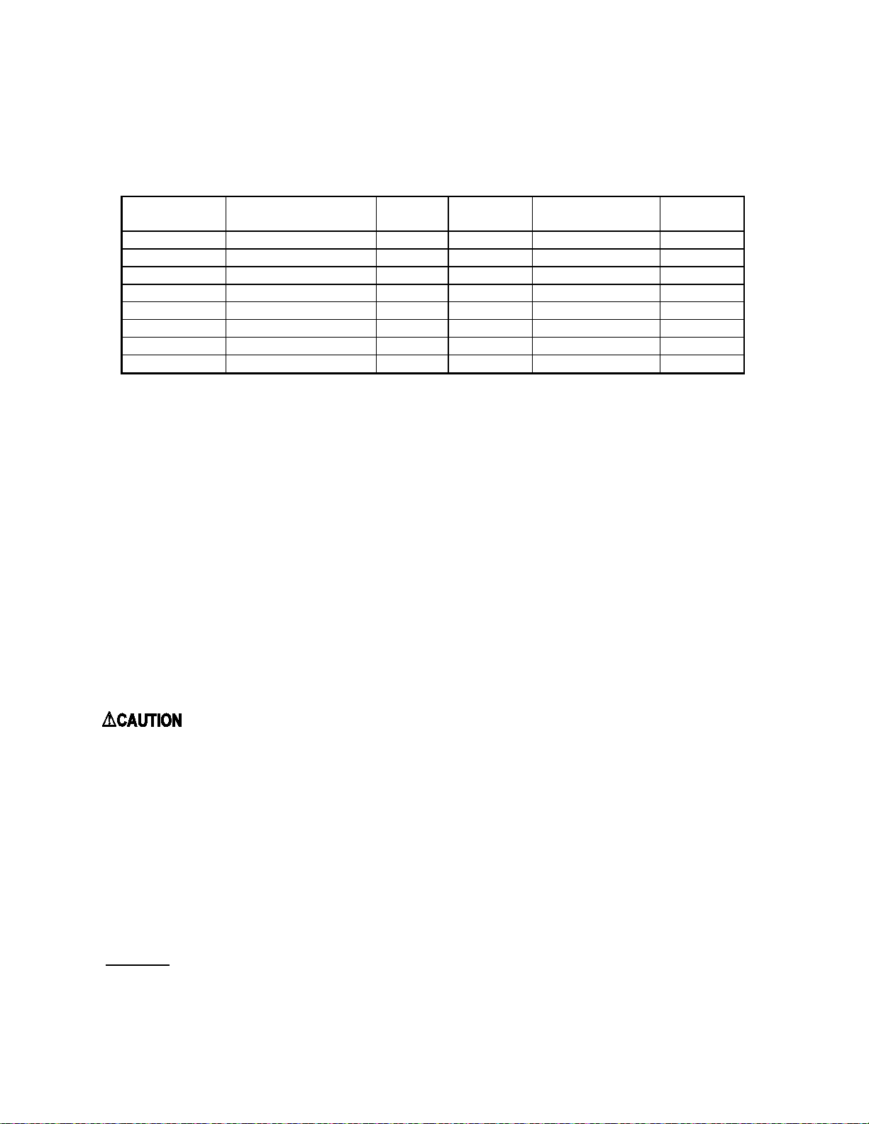
B1. CDB1 HORIZONTAL APPLICATION
The CDB1-50, 75, 100, and 125 furnaces may be installed in a horizontal position by placing the furnace on the left
or right side (as viewed from the front in the upright position).
For left or right horizontal applications of the CDB1 ser ies units, the rollout switch located on the burner box must
be moved to the pre-punched mounting holes on t he side of the burner box. Screws are provided in p re-punched
holes at the required limit location. Remove these screws and use them to mount the limit to new location. Utilize
previously removed limit mounting screws to fill voided holes at previous limit location (See Figure 1).
For a right side hor izontal application of the CDB1 series units, the hose from the single tap pressure switch (top
switch) is already connected correctly (See Figure 1).
For a left side horizontal applica tion of the CDB1 series units, the hose from the single tap pressure switch (bottom
switch) must be moved to the lower front tap on the face of the collector box. Use the black cap removed from this
tap to plug the original pressure switch tap.
NOTE: T he hose, when moved, must be shortened (cut) to ensure that no excess hose exists to cause a sag, loop, or
"water trap".
For a right side horizontal application of the CDB1 series units, the auxiliary limit switch located on the right side of
the house air blower must be moved to the bracket on the opposite (left) side of the blower (See Figure 1).
NOTE: When the CDB1 is installed as horizontal unit, it is imperative that the auxiliary limit switch and bracket be
located on the upper side of the house air blower; the burner rollout switch located on the burner box be relocated to
the side of the burner box; and that the hose from the single tap pressure switch be connected to the lower tap on the
front of the collector box (See Figure 1).
accessory, part number 350225. If
7
Page 14
All installations and services must be performed by qualified service personnel.
Figure 1
The horizontal furnace installation should be on a service platform large enough to allow for proper clearances on all
sides and service access to the front of the furnace (See Table 1). If the furnace is suspended, it must be supported at
both ends and in the middle with clearance allowed for removal of both access doors. Gas supply line contact is only
permissible between lines
joists, studs, or framing (See Figure 1).
Equipment must be installed in accordance with regulations of the Nat ional Board of Fir e U nde rwriters and
the National Fuel Gas Co de . Authorities having jur isdic tion should be consulted before installations are
made.
formed by the intersection of the top and two sides of the furnaces casing and the buil di ng
C. Replacing An Existing Furnac e From A Common Vent
: These furnaces may NOT be common vented with any other appliance.
8
Page 15

All installations and services must be performed by qualified service personnel.
D. General Requirements For Venting Models CHB1 / CDB1
The CHB1 / CDB1 furnace venting system must be installed by a qualified service person in accordance with local
installation codes and these instructions. In the absence of applicable local codes, conform to the National Fuel Gas
Code, NFPA 54 /ANSI Z223.1-2002, or latest edition thereof.
Installation shall, at least, conform to the following requirements.
1. The exhaust vent / combustion air intake terminations specified by Thermo Products, in this manual, shall
be used.
2. All plastic pipe and pipefitting s sourced to complete the exhaust vent and air intake systems shall be
constructed of rigid PVC (polyvinyl chloride) thermoplastic. All components shall have a wall
thickness equivalent to Schedule 40 series materials.
In addition, all sourced PVC components shall be listed b y a nationally recognized testing agency (e.g.
NSF, UL, etc.) as conforming to one (1) or more of the following design standards.
PVC Pipe Designation Design Sta ndard
Cellular Core ASTM-F891
DWV (Drain-Waste-Vent) ASTM-D2665
Schedule 40 ASTM-D1785
3. The exhaust vent pipe and combustion air pipe shall be at least as large as the exhaust vent / air intake pipe
specified by Thermo Products. Size reduction is never permissible. The req uired exhaust vent / air intake
pipe sizes are:
• nominal 2-inch diameter IPS, Schedule 40 series, PVC thermoplastic pipe, for models CHB1–50 / –
75 & CDB1–50 / –75, or
• nominal 3-inch diameter IPS, Schedule 40 series, PVC thermoplastic pipe, for models CHB1–100 / –
125 & CDB1–100 / –125.
4. The furnace model series CHB1 / CDB1 shall not be common vented with any other app liance, includ ing
those burning so lid fuels.
5. All horizontal runs of exhaust vent pipe shall slope upward at least ¼ inch per foot from the outlet of the
furnace (for the model series CHB1), or the outlet of the drain tee (for the model series CDB1) to the vent
termination, beyond the outside wall. This slope will permit proper drainage of the condensate.
Horizonta l runs of air intake pipe shall slope downward at least ¼ inch per foot from the outlet of the last
elbow or last horizontal run, before exiting the wall, to the intake termination beyond the outside wall. This
slope will permit proper drainage of any precipitation that enters the intake pipe.
6. The exhaust vent pipe shall be supported at every joint (no more than 4-feet between supports) to
prevent pipe blockage due to condensate trapped at a local low point, or sag, in the vent system.
7. The maximum permissible length of pipi ng (consisting of a combination of straight pipe and a
corresponding number of elbows) permitted is:
• 75 equivalent feet, for the exhaust vent system, and
• 70 equivalent feet, for the combustion air intake system
8. The maximum quantity of Schedule 40 series, type DWV thermoplastic pipe elbows allowed in each system
is listed in Table 2. When counting pipe elbo ws, all elbows used in the exhaust vent or combusti on air
9
Page 16
All installations and services must be performed by qualified service personnel.
Thermoplastic
(Nominal)
Exhaust or
Length (ft.)
Maximum
Maximu
Elbows 2
Exhaust or
Length (ft.)
Maximum
Maximu
Elbows 2
CHB1 / CDB1-50
35 8 7 - -
-
CHB1 / CDB1-75
CHB1 / CDB1-100
Not Permitted
35 8 7
CHB1 / CDB1-125
intake systems must be considered. This includes all elbows, or equivalent pipefittings, used inside the
furnace jacket in addition to those used to construct the termination. Furthermore, a credit of 5-feet of
straight pipe may be taken for each elbow, up to maximum of three (3) elbows, which is dropped from the
maximum permissible number for each system.
Table 2: Maximum Permissible Exhaust Vent and Combustion Air Intake Lengths When Using the Maximum
Quantity of Elbows
Pipe Vent Size
Furnace Model
Intake
Straight
Pipe
2 in. Diameter IPS
Qty. of
Exhaust
Elbows
1,2
m
Qty. of
Intake
Intake
Straight
Pipe
3 in. Diameter IPS
Qty. of
Exhaust
Elbows
1, 2
m
Qty. of
Intake
Superscripts:
1
The drain tee supplied with CHB1 / CDB1 furnace model series is considered equivalent to one (1),
90° elbow.
2
Two (2), 45° elbows can be substituted for one (1), 90° elbow.
Care should be taken to design the shortest possible intake and exhaust systems. Each system should contain
as few elbows as possible to insure the satisfactory operation of the furnace. However, system length
should never be less than 8 ft of pipe with two (2), 90 deg. elbows. For best overall operation of the
combustion system, we recommend the actual equivalent lengths for both the constructed intake and the
exhaust systems have approximately the same value.
9. Use a saw designed to cut thermoplastic pipe. All cuts should be made at right angles to the pipe wall.
Smooth jagged edges and remove all burrs and strings. All pipe joints must utilize standard PVC
Schedule 40 series, DWV type elbows, couplings, and f ittings. Clean all pipe surfaces at connections
using a fine abrasive material or approved PVC cleaner (primer). Secure all pipe joints using suitable
permanent PVC pipe solvent cement. Joints are NOT to be made by simply gluing raw edges of butted
together vent pipe.
Piping joints inside the furnace vestibule should be sealed with silicone caulk, rather than pipe cement, to
allow for disassembly and removal of piping, if necessary, during maintenance.
NOTICE: DO NOT use silicone caulk to seal the pipe sleeve or coupling to the metal air intake collar
on the burner box. Securing the sleeve or coupling to the collar using a screw is sufficient.
10. Vent connections shall be checked for leakage with the furnace induced draft blower running and with the
vent termination blocked. Use a mild soap and water solution to check for leaks.
11. Vent pipe passing through an unhe ated space s hall be insulate d with 1-inch thick, foil-faced fiberglass
insulation, or equivalent, to prevent freezing of condensate within the pipe.
12. No clearance is required from the outer surface of the thermoplastic piping to combustible materials for fire
hazard prevention.
13. Thermo Products does not require screens be installed in the exhaust vent and air intake piping. However,
optional stainless steel screens are available from Thermo Products, should the homeowner request them.
10
Page 17
All installations and services must be performed by qualified service personnel.
NOTICE: The furnace model series CHB1 / CDB1 may be vented either through the sidewall or the roof.
For sidewall instructions, continue to the following section. For roof venting, refer to Section III G, of this
manual
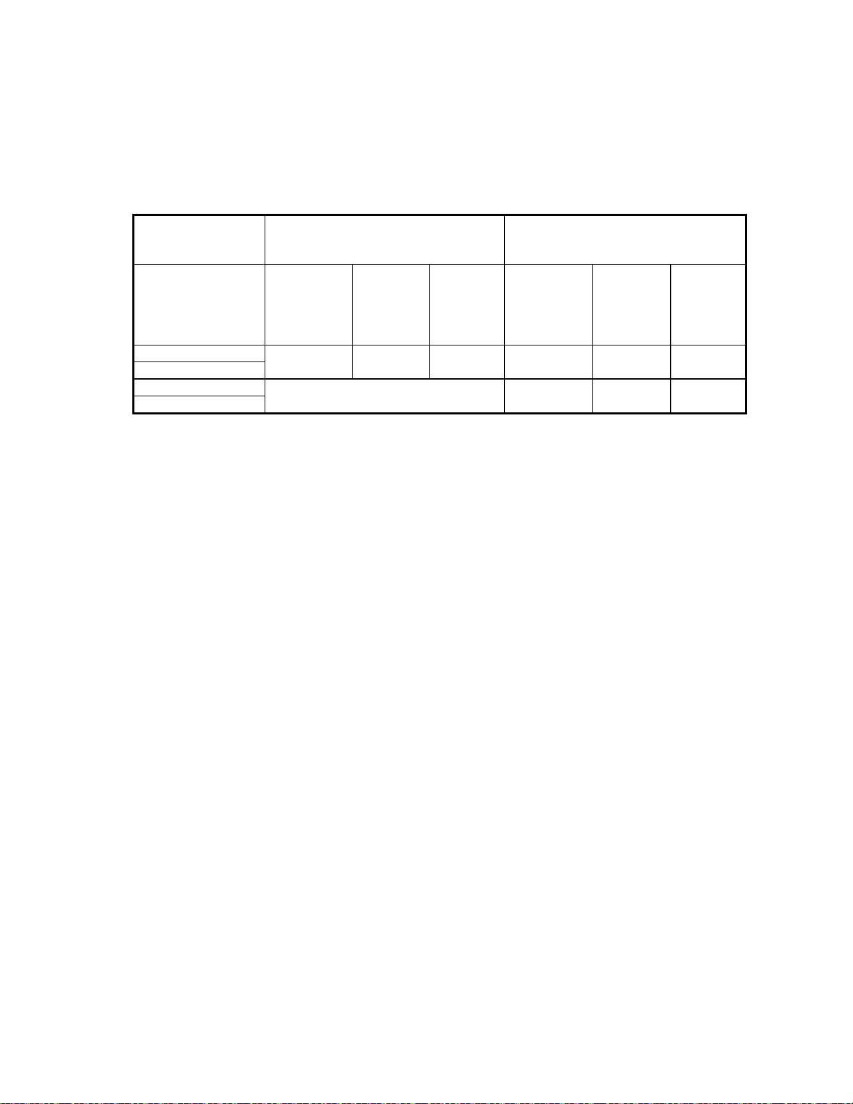
E. Direct Venting Through a Sidewall
1. Ve nt and combustion air pipes may pass t hrough a maximum wall thickness of 18 i nches. The minimum
wall thickness is 2 inches. Referring to Figure 2, the maximum distance from the outer wall to the center of
the elbow is 12 inches.
Figure 2: Proper Direct Vent Terminations (RH & LH views) and Vent Termination Only w/o
Outside Combustion Air Intake (RH view)
NOTICE: If exterior sidewall building materials are subject to de gra dation from contact with flue gases or
moisture, a min imum 24-inch diameter shield shall be fabricated from stainless steel or UV-resistant plastic
sheet. The protective shield shall be installed aro und the vent pip e on the outside wall.
2. The exhaust vent termination elbow shall be installed in accordance with these instructions and any
applicable local codes. Refer to Figures
2 and 3 for typical examples of proper terminations.
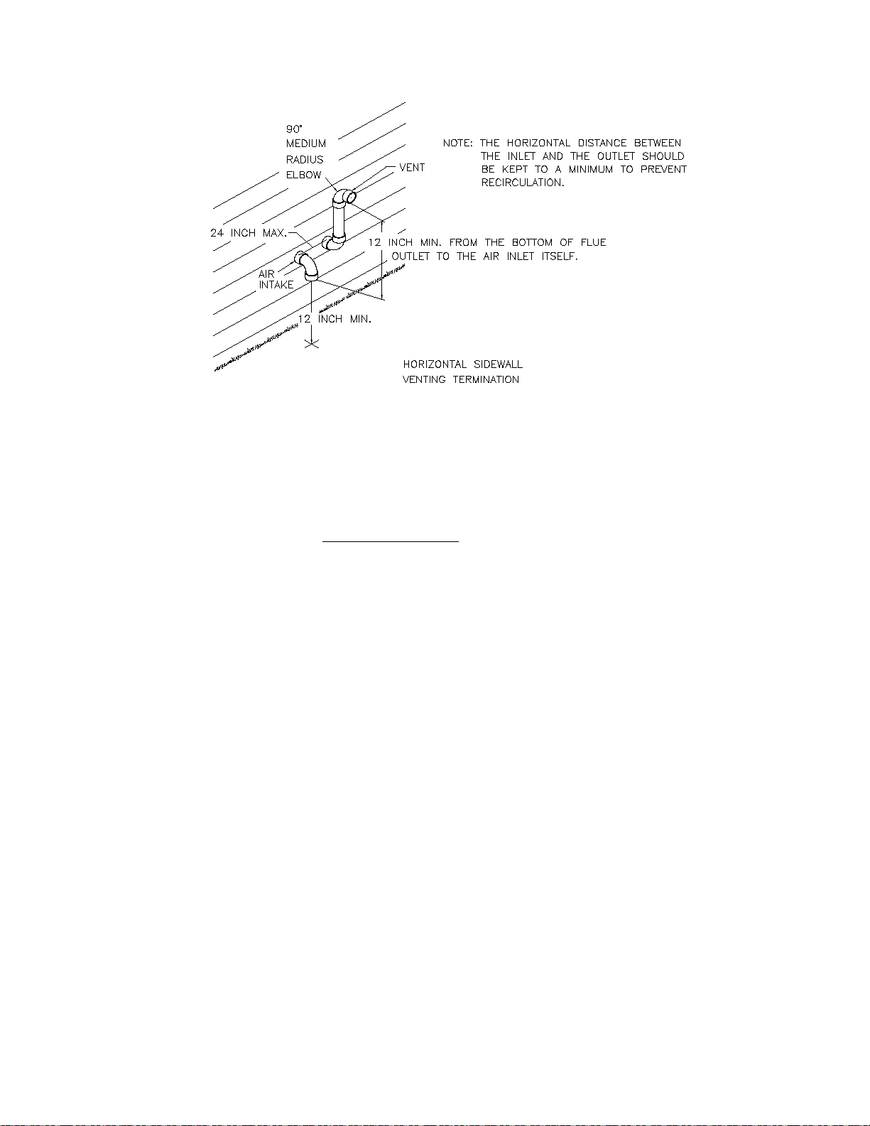
a. T he exhaust vent termination must be installed in the same atmospheric pressure zone (i.e. on the same
wall) as the air intake termination.
b. The bottom edge of the vent termination elbow must be installed at least 12-inches above the outlet of
intake termination elbow.
c. The horizontal distance between the inlet and exhaust terminations should be minimized, when
possible, and should never exceed 24-inches.
d. The vent and intake systems should utilize the same numbers of elbows and approximately the same
length of straight pipe to reach the outside termination.
11
Page 18
All installations and services must be performed by qualified service personnel.
Figure 3: Typical Relative Locations of Direct Vent Terminations When Sidewall Venting
3. Exhaust Vent Terminal Location Clearance Requirements
a. The vent terminal shall be located at least 3-feet above any forced air inlet located within 10-feet. Refer
to Figure 4 for a depiction of the minimum required clearances between vent terminations and building
features according to the National Fuel Gas Code (NFGC).
b. The vent terminal shall be at least 12-inches below, 12-inches horizontally from, or 12-inches above,
any door, window, or gravity air inlet into a building. The bottom of the vent terminal shall be located
at least 12-inches above grade.
c. The vent terminal shall not be located:
• over public walkways or over an area where wetting of surfaces by condensate, or water vapor,
could create a nuisance or hazard,
• near soffit vents, crawl space vents, or other areas where condensate or water vapor could create a
nuisance, hazard, or cause property damage, and
• where wetting of component s by condensate, or water vapor, could be detrimental to the operation
of pressure regulators, relief valves, or any other equipment.
d. The vent terminal shall be installed a minimum of 14-inches from any obstruction and 3-feet from an
inside corner of an L-shaped structure.
12
Page 19

All installations and services must be performed by qualified service personnel.
Figure 4: NFGC Minimum Clearances Between the Vent Terminal and Various Building Features
4. Vent Terminal Location Guidelines
13
Page 20

All installations and services must be performed by qualified service personnel.
: Bushes, shrubs, or any vegetation that may restrict the flow of flue products must be kept
away from vent and air intake terminations. Terminations must also be kept clear of any leaves, weeds,
combustible mate rials, snow, and ice build-up. Avoid locating the vent terminal over areas where
dripping of condensate, or small pools of acidic condensate, could create a problem.
In addition to following any local code requirements, when possible, utilize the guidelines below in locating
the vent terminal to help insure trouble-free operation of a sidewall vented furnace:
• Avoid locating the vent terminal on a wall facing prevailing winds and wide-open areas. When
impractical, choose a location that protects the vent from strong winds, such as behind a fence or
hedge.
• In geographical areas with considerable snowfall, it is advisable to locate the vent terminal much higher
than the minimum 12-inches abo ve ground to p revent blockage by snow accumulation or drifting.
• The vent and combustion air terminations shall be checked periodically, at least at the start of each
heating season, for restriction or blockage from foreign material in the exhaust vent or in the air intake
piping. Clean the air intake and vent terminations when necessary.
E1. Single-Pipe (Sidewall) Venting Option
NOTICE: When possible , we recommend all furnace of the model series CHB1 / CDB1 be installed to
utilize outside combustion air. The use of outside combustion air usually results in t he most energy
efficient, nuisance free, and long-lived operation of the furnace.
NOTICE: Heat exchanger failure accelerated by contaminated combustion air will void the furnace heat
exchanger limited lifetime warranty.
This furnace may be horizontally, i. e. sidewall, vented using an exhaust vent pipe alone witho ut drawing in
outside combustion air. When single-pipe, sidewall venting a furnace, combustion air is drawn from the indoor
space. This type of installation is not classified as a direct vent installation. However, the same exhaust venting
guidelines apply as for a direct vent installation, except the exhaust termination will be similar to the air intake
of the "two- pipe", direct vent installation. Refer to depictions of proper intake terminal installations in Figures 2
and 3. Referring to the left-hand (LH) sketch in Figure 2, vent termination will consist of one (1), 90° elbow,
opening downward.
When indoor air is used for combustion, measures should be taken to prevent drawing in corrosive chemicals
vapors or gases with the combustion air supply. Such chemicals include, but are not limited to, chlorinated
and/or fluorinated hydrocarbons such as found in refrigerants, aerosol propellants, dry cleaning fluids,
degreasers and removers. Other harmful compounds may come from bleaches, air fresheners or mastics. Vapors
from such products can form reactive acid producing chemical species when burned in a gas flame. The life of
the furnace could be reduced should acidic compounds form within the furnace.
F. Installation Of Outside Exhaust / Intake Terminations
1. After determining appropriate installation locations (suitable locations must observe all clearances specified
in this manual), mark and cut two (2) holes in the outside wall of the following sizes for the outdoor
terminal(s),
• 2-3/8 inch diameter, for furnace models CHB1 / CDB1-50 and CHB1 / CDB1-75, or
• 3-1/2 inch diameter, for the furnace models CHB1 / CDB1-100 and CHB1 / CDB1-125.
14
Page 21

All installations and services must be performed by qualified service personnel.
2. Measure and cut two (2), 2-inch diameter thermoplastic pipes 1-1/2 inches longer tha n t he depth of the wall.
(Cutting the pipe longer leaves a ¾ inch connection allowance at both ends of the pipe.) For 3-inch diameter
PVC pipe, leave a 3-inch allowance for end connections. Using PVC pipe cement, glue a PVC elbow or
coupling fitting to one (1) end of each pipe.
Before inserting the pipe through the wall, mark the other end of the pipe so the elbow orientation can be
determined. Also, if a protective shield (refer to Section E., passage 1. of this manual) will be used on the
exterior surface of the wall, it should be installed at this time. From the inside, glue a coupling fitting to
each pipe, using PVC pipe cement, while being careful to maintain the proper orientation of the termination
elbow(s). Complete the assembly of the outlet and inlet as shown in Figure 5, making sure that the spacing
between the inlet and outlet complies with that noted in Figure 3.
Figure 5: Typical Co nst r uction Details of Sidewall Vent and Air Intake Terminations
3. Finish the vent installation by caulking the annulus to seal around the two (2) holes where the thermoplastic
pipes pass through the wall.
4. To prevent foreign material, insects, or small animals from entering the pipes, an optional vent or intake
terminal (stainless steel) screen is available from Thermo Products under part no. 320226 for 3” vent and
320219 for 2” vent.
5. Optional Direct Vent Terminations
Three optional vent kits are available for direct vent terminations, refer to Figure 6.
• The concentric vent kits (Thermo Products p/n AOPS7488 & AOPS7489) provide a means for the vent
and intake to be installed through a single opening in the roof or exterior wall. Kit p/n AOPS7488
requires a 4” inch diameter hole and is used on furnace models CHB1/CDB1-50 & 75. Kit p/n
AOPS7489 requires a 5” inch diameter hole and is used on furnace models CHB1/CDB1-100 &125.
• The sidewall vent cap (Thermo Products part no. 370191) is a cover installed over the exhaust vent and
air intake pipes on the exterior of the building. For horizontal sid e wall vent applicatio ns only. This kit
may be used on any size furnace in the CHB1/CDB1 family.
Install these optional kits according to the instructions provided with each kit. The location and clearance
requirements are identical to those of the standard vent terminations described in this manual.
15
Page 22

All installations and services must be performed by qualified service personnel.
370191
SIDE WALL VENT KIT
VERTICAL
HORIZONTAL
AOPS7488 / AOPS7489
CONENTRIC VENT KIT
Figure 6: Optional Direct Vent Kits for the CHB1 / CDB1 Model Series of Furnaces
G. Connecting The Furnace To R oof Exhaust / Intake Terminations
If it is not desirable, or feasible, to vent the furnace through a sidewall, it may be vertically vented through the
roof. Installation shall conform to the following guidelines, which are illustrated in Figure 6A, below.
1. The outlet of the exhaust vent and the inlet of the combustion air intake, i.e. the terminations, shall be a
minimum of 12-inches above highest anticipated snow level.
2. The exhaust vent outlet must be installed a minimum of 12-inches above the air intake inlet.
3. Where exposed to prevailing winds, the combustion air intake shall be installed upwind of the vent outlet.
4. The exhaust vent and combustion a ir intake shall be a minimum of 3-inches and a maximum of 24 inches
apart.
NOTICE: When the vent termination is installed correctly, a draft should NOT be present in the system
during the furnace off-cycle.
Figure 6A: Typical Rooftop Vent and Air Intake Termination Construction Details
16
Page 23

All installations and services must be performed by qualified service personnel.
H. Exhaust / Intake Piping And Condensate Drain Connections At F ur nace
1. Figures 6B, 7, and 8 follow depicting typical exhaust vent and air intake connections for the furnace model
series CHB1 and the CDB1, respectively, as well as a list of required parts to correctly install each system.
Figure 6B: Required Exhaust V ent and Air Intake Piping for CHB1 Furnace
17
Page 24

All installations and services must be performed by qualified service personnel.
Figure 7: Required Exhaust Vent and Air Intake Piping for CDB1 Furna c e in Downflow Applic ations
18
Page 25

All installations and services must be performed by qualified service personnel.
Figure 8: Required Exhaust Vent and Air Intake Piping for CDB1 Furnace in Horizontal Applic ations.
2. Co nnecting The Exha ust Vent To The Inducer
a. Slip the end o f the 2-inch diameter PVC elbow (for the model CDX1 in horizontal applications, the 2-
inch diameter PVC tee assembly) over the outlet of the inducer blower assembly. Measure the length of
2-inch diameter thermoplastic pipe needed to clear the furnace side casing, while allowing for
installation of a 2-3/8 inch length of reinforced rubber hose, used as a c oupling, within the cas ing of the
furnace. Cut the measured lengths of 2-inch diameter PVC pipe be ing sure to allow a sufficient length
of pipe for connections. Refer to Figures 9, 10 and 11 for assembly details.
NOTICE: For the models CDB1-50 / -75, a length of 2-inch diameter PVC pipe and a 2-inch
diameter PVC tee assembly are supplied with each furnace. For the models CDB1-100 / -125, a 3-inch
x 2-inch diameter PVC reducer is also supplied.
19
Page 26

All installations and services must be performed by qualified service personnel.
NOTICE: For models CDB1-100 and CDB1-125 used in horizontal applications, immediately
transition from 2-inch to 3-inch diameter pipe b y installing the 3-inch x 2-inch diameter PVC reducer
just outside the furnace casing. The remainder of the venting system leading away from the furnace
must be composed of 3-inch diameter PVC pipe and pipefittings only. Refer to ite m E in Figure 8.
b. After prepa ration of the internal 2-inch diameter PVC pipe sections, put a thin bead of a silicone rubber
type sealant around the outlet flange of the inducer. Slip the 2-inch diameter PVC elbow (for the model
series CDB1 in horizontal applications , a 2-inch diameter PVC tee) over the inducer outlet flange.
Drive one (1) #8 x 3/4 inch sheet metal screw with black protective coating (supplied with furnace)
through the elbow and into the outlet flange of the inducer to secure the elbow in place.
Figure 9: Typical Internal
Vent Piping Arrangement for
the Furnace Model Series
CHB1.
Figure 10: Typical Internal
Vent Piping Arrangement for
the Furnace Model Series
CDB1-100 / -125.
Figure 11: Typical Internal
Vent Piping Arrangement for
the Furnace Model Series
CDB1-100 / -125 in RH
Horizontal Applications.
c. Using PVC cement, glue the pre-cut 2-inch diameter thermoplastic pipe, from step (a) above, to the 2-
inch diameter PVC elbow (for the model series CDB1 in horizontal applicatio ns, the 2 -inch diameter
20
Page 27

All installations and services must be performed by qualified service personnel.
PVC tee). Couple the drain tee assembly to the pre-cut 2-inch diameter PVC pipe using the reinforced
rubber hose and the two (2) band clamps supplied.
NOTICE: All PVC thermoplastic pipe must be supported beginning directly over the exhaust
vent tee assembly, then every 4-feet thereafter, and at every joint. Trial fit the entire exhaust vent
and air intake piping systems, making sure the slope and length of the piping are correct, before
permanently assembling the pipe components.
If the vent pipi ng is run through an unco nditioned space, it must be ins ul ated with 1-inch thick
foil-faced fiberglass insulation, or an equivalent product.
3. Co nnecting The Combustion Air Intake Piping
: Outside combustion air must NOT be drawn from an area directly adjacent to a pool, hot
tub or spa. Measures should be taken to prevent the entry of corrosive chemicals or vapors into the
combustion air supply. Such chemicals include, but are not limited to, chlorinated and/o r fluorinated
hydrocarbons such as found in refrigerants, aerosol propellants, dry cleaning fluids, degreasers and
removers. Oth er harmful compounds may come from bleac hes, air fresheners o r mastics. Vapors from
such products can form reactive acid producing chemical species when burned in a gas flame. Should
acidic compounds form in the furnace they may significantly reduce the useful life of the furnace.
a. For the models CHB1–50 / –75 and CDB1–50 / –75, install a 2-inch PVC elbow with sleeve and
coupling (for models CHB1–100 / –125 and CDB1–100 & –125, a 3-inch PVC elbow with sleeve) on
the inlet of the burner box. Measure the length of pipe needed to clear the casing. Be sure to allow
sufficient length to account for insertion of the pipe into the elbow at the burner box and the elbow, or
coupling fitting, on the end. Cut the pipe to le ngth.
b. After preparation of the thermoplastic pipe, drive one (1) #8 x 3/4 inch sheet metal screw with black
protective coating (sup plied with furnace) through the PVC coupling, or s leeve, into the metal collar of
the burner box to secure the piping in pla ce.
NOTICE: DO NOT apply silicone rubber type sealant or PVC cement to the joint at the
thermoplastic piping connection to the metal burner box collar. Attach the PVC elbow to the
sleeve and then to the coupling where required, using silicone rubber type sealant, refer to
Figure 12.
c. Insert the precut 2-inch (o r 3-inch) thermoplastic pipe into the elbow at the burner box and to the
elbow, or coupler, just outside the fur nace using a silicone rubber type sealant. To properly make these
seals, run a thin bead of silicone type sealant around the circumference of the PVC pipe, about 3/8 inch
from either end. Insert the straight pipe section into the appropria te c ouplings and elbows and rotate 1/4
turn. Silicone rubber type sealants remain pliable after the initial setup period has passed allowing for
relatively easy disconnection of the air intake system, should the burner assembly require removal at a
later date, refer to Figure 12.
NOTICE: When applying silic one sealants, ensure that no excess sealant is pushed into the inside
opening of the pipe. This may cause flow restriction within the piping. If possible, always apply
the sealant to the male component of the piping joint.
21
Page 28

All installations and services must be performed by qualified service personnel.
DO NOT! SILICONE OR SEAL
THIS CONNECTION IN
ANYWAY. MUST BE LOOSE
FIT WITH LEAKAGE BETWEEN
PVC AND METAL COLLAR.
Figure 12: Typical Internal Air Intake Piping Arrangement for All Furnace Models
d. After trial fitting the entire combustion air intake system, use a PVC cement to glue all connections in
place, except the length of pipe between the combustion air fitting on the burner box and the first
fitting.
e. If the combustion air piping is installed in a warm, humid place, such as a laundry room or above a
suspended ceiling, it must be insulated with a 1-inch thick, foil-faced fiberglass insulation, or an
equivalent product, to help prevent the outside surface of the pipe from sweating.
I. Condensate Drain Line And Tra p A ssembly
1. The following diagrams depict typical condensate drain and trap connections for the furnace models series
CHB1 and CDB1, r e fer to the illustrations in Figures 14, 15, and 16.
Figure 14. Condensate Trap Assembly Mounted On the Model Series CHB1
22
Page 29

All installations and services must be performed by qualified service personnel.
Figure 15. Condensate Trap Assembly Mounted On the Model Series CDB1 In a D ownflow Application
Figure 16. Condensate Trap Assembly Mounted On The Model Series CDB1 In RH Side Horizontal
Application
2. Determine from which side of the furnace the condensate disposal line will be run.
23
Page 30

All installations and services must be performed by qualified service personnel.
NOTICE: On the model series CHB1 / CDB1 the condensate disposal line must be on the same side
as the flue outlet or, in the case of a horizontal application, the bo ttom of unit.
Drive two (2) #8 x 3/4 inch sheet metal screws with black protective coating (supplied with furnace) to
attach the condensate trap to the furnace casing. Pilot holes are provided on both sides of the casing for
mounting the trap.
NOTICE: When the CDB1 series unit is used in a horizonta l application, the connection of the
drain hose to the collector box must be changed from the standard, factory-supplied location to a lower
location on the collector box to permit proper drainage of condensate from the furnace. A knockout has
been provided in the furnace side casing for the drain hose to exit. The connection change can be
accomplished as follows. Refer to Figure 16 for a depiction of a properly completed relocation.
a) Locate and disconnect the drain hose from the standard connection location at the collector box.
b) Locate and uncap the drain at the bottom (with the furnace lying on a side) of the collector box.
c) Connect the drain hose from Step (a) to the uncapped bottom drain from Step (b).
d) Close off the previous drain connection from Step (a) with the cap removed in Step (b).
3. Attach one (1) drain hose (a length of 11/16 inch O.D. clear, colorless tubing) to the front
connection (on the model series CHB1) or the bottom connection (on the model series CDB1) of the
condensing coil cover plate.
Insert the snap-in-place plastic bushing, provided in the furnace parts package, into the proper hole in
the furnace casi ng to prevent cut s in the drain tubing. Route the drain tubing through the bushing.
When making connecti ons with the clear tubing, carefully ro ute the tubing in a manner to prevent
kinking or abrasion of the tubing.
Slip the free end of the drain hose over the hose barb on one (1) side of the plastic hose barb tee
provided in the CPVC (chlorinated po lyvinyl chloride) thermoplastic condensate tr a p assembly.
Secure the drain hose with the spring-type hose clamp provided in the parts package.
4. Trial fit the second drain hose (a length of 11/16 inch O.D. clear, colorless tubing provided in the
furnace parts package) from the hose barb on the bottom of the PVC exhaust vent drain tee to the
plastic hose barb tee provided in the condensate trap assembly. Make sure the hose is long enough not
to kink or be otherwise restricted once installed. Mark the minimum length of drain hose required for
the application. Remove any extra length from the drain hose. Attach the drain hose to the hose barb
on the other side of the condensate trap tee. Slip the other end of the drain hose on to the hose barb of
the PVC drain tee assembly; refer to Figure 15 for an illustration. Use the spring-type hose clamp(s)
provided in the parts package to secure all connections.
5. Plan, source, and install a condensate drain line using ½ inch diameter CPVC (chlorinated polyvinyl
chloride) thermoplastic pipe and pipefittings. Route the line in the shortest possible manner to reac h a
nearby drain. Secure all joints using CPVC cement. For gravity drainage, the condensate drain line
must maintain a minimum ¼ inch per foot downward slope toward the drain. The drain line must be
watertight, supported, and secured such that it cannot be easily moved.
NOTICE: If an air conditioning condensate drain line is combined with the furnace condensate drain
line, the air conditioning evaporator coil must have a separate trap installed ahead of the connection
joint.
24
Page 31

All installations and services must be performed by qualified service personnel.
6. A condensate pump may be required when,
• a suitab le drain is not present,
• the drain is above the trap outlet level on the furnace, or
• the drain line cannot be sloped downward its full length to the drain.
If gravity drainage of the condensate from the furnace to a drain is impractical for any of these reasons,
a condensate pump (part # 350225) is available from Thermo Products. Follow the pump
manufacturer’s instructions for proper installation.
7. CAUTION: Continual exposure to co nde nsate may injure plants and damage certain building
materials, including many metals, wood, stone, and concrete.
Flue gas condensate is slightly acidic with a pH of about 3.5. (A pH level of 7.0 is considered neutral.
Carbonated cola drinks with a pH of 3.1 are actually slightly more acidic than condensate.) If local
codes require an acid neutralizing kit, a kit is available from Thermo Products under part no. 320095.
Follow the instructions enclosed with the neutralizing kit for proper installation.
8. The conde ns ate piping in the furnace and the drain system should b e flushed out at the start of every
heating season. This will ensure trouble free operation and will keep the acidity level well above a pH
of 3.4, i.e. more towards neutral.
To flush the condensate drain system, follow these steps.
a. Turn off electrical power to the furnace at the disconnecting switch and adj us t the room thermostat
to “OFF”, or to the lowest temperature setting.
b. Flush the drain system by removing the drain hose from the secondary heat exchanger coil drain
nipple and running tap water into the open end of the tubing. Run at l east a quart of water through
the drain system or more, until the water leaving the drain system is clear and colorless in color
and free of any particulate matter.
c. Replace the drain tubing by pushing it firmly onto the nipple. Make sure the spring-type hose
clamp is returned to the original position to prevent leaks.
d. If any of the electrical controls are inadvertently wetted during the flushing process, dry them with
a soft cloth and wait 24 hours before operating the furnace.
e. Adjust the room thermostat to the “HEAT” position, or to the desired temperature, and r e sto re
electrical power to the furnace.
J. GENERAL GAS PIPING
: Because of the potential of odorant fade, a gas leak may not be detected by smell. If this
furnace is installed below grade, contact your gas supplier for a gas detector.
1. Left and right gas supply piping - These furnaces are set-up to be gas piped through e ither the left or right
side by using a street elbow and a straight pipe. For the purposes of service, it is recommended that the gas
union be located inside the furnace, when possible.
25
Page 32

All installations and services must be performed by qualified service personnel.
Figure 18
2. A drip leg must be used on both LP and natural gas installations prior to the furnace in order to tr a p oil,
condensate and other impurities which might otherwise lodge in the gas valve or plug the burner orifice . A drip
leg shall be provided at the outlet of the gas meter when there is excessive condensation between the gas meter
and the furnace. Failure to install a drip leg may void the limited warranty on the furnace.
: All gas piping must be leak tested using a soap and water solution (when the gas is turned on)
following the procedure outlined in Section III, J, of this manual. A final test for gas leakage must be made after
purging the gas line (refer to Section IV, B, of this ma nual). This test m ust be conducted with the unit op erating
and should include the furnace piping and gas valve. Never use an open flame to check for a gas leak.
: Care must be taken not to wet electronic components during leak test. Wetting the primary
ignition module may damage its circuitry and cause a hazardous situation. Dry moisture from all leads and
terminals if wetting occurs. Wait at least 24 hours for the circuit to fully dry bef ore energizing the burner circuit.
J1. REQUIREMEN TS A ND SIZING OF DUCT WORK
The duct system must be sized and installed by a qualified installer or service person, following the design standards
of the Air Conditioning Contractors of America (ACCA) or ASHRAE.
1. When it is located in the same room as the furnace, a return air register must be installed a minimum of 20 feet
away from the furnace.
2. The return air duct shall also be sealed to the furnace and also terminate outside of the furnace space, if supply
ducts carry circulated air to areas outside the space containing the furnace.
3. The return air duct system must equal the supply air duct system in its capabilities. Use a supplier's catalog for
proper sizing of outlet and return air registers and grills to ensure that they meet the CFM requirements of the run to
which they are connected.
26
Page 33

All installations and services must be performed by qualified service personnel.
4. If the furnace is used in connection with an air conditioning evaporator coil, the furnace must be installed parallel
with or on the upstream side of the coil, to prevent condensation in the heat exchanger. If the evaporator coil is
installed with a parallel flow arrangement, dampers or other means to control flow of air should be installed to
prevent chilled air from entering the furnace. If such a device is manually operated, it must be equipped with a means
to prevent operation of either the furnace or air conditioner unless it is in the full heat or cool position.
We recommend that the outlet duct be equipped with a removable access panel to allow for visual inspection of the
heat exchanger to check for leakage or to allow for insertion of a probe sampler in the air stream. This removable
access cover should be attached to ensure there is no air leakage.
5. The duct system shall be sized for the maximum CFM requirement of the installation whether it is for heating or
cooling. Two common rules for heating and cooling follow:
A. 400 CFM (1200 BTU's) per ton of cooling is required.
B. 14 CFM of heating per 1000 BTU's of furnace output based on its steady state efficiency and a 55° to 85°
temperature rise.
EXAMPLE: Heating output of a furnace is 100,000 BTU/HR
100,000 BTU x 14 cfm = 1400 CFM
1000 BTU
Air conditioning installed is 4 tons x 400 CFM = 1600 CFM or 48,000 BTU’s. NOTE: The duct system must be
sized for the larger CFM requirement for cooling. If only 3 tons 36,000 BTUs of cooling x 400 CFM = 1200 CFM
was installed, the duct would have to be sized for the 1400 Cfm heating requirement.
Figure 18A
All trunk lines, take-offs, registers and grill-free areas must be figured when determining the air handling capacity of
a duct system. One can obtain the necessary duct system size by utilizing the chart below. (For example, see Figure
18A.) Use a supplier’s catalog for prope r sizing of outlet and return air registers to insure that the register will meet
the CFM requirements of the run to which it is connected.
The main trunk lines, take offs, registers and grills of the supply return air duct system must have an adequate square
inch area to move the desired CFM in order to achieve proper movement. The following chart shows the CFM ai r
handling capability based on a 0.1” SP loss in the supply duct system. The total external static pressure should not
exceed .2 inches water column.
27
Page 34

All installations and services must be performed by qualified service personnel.
DUCT SIZES FOR HOMES, QUI ET OFFICES, OR SIMILAR INSTALLATIONS
TABLE 2A
Each of the system compo nents (tr unk lines, ta ke offs, runs a nd registe r and gril l-free areas) must be properly sized
and matched together to ensure the necessary air handling capacity of a duct system. A 12" x 8" duct with a 400
CFM capacity for example will not flow 400 CFM if the register(s) to which it connects only flow a total of 200
CFM.
The speed of the blower motor may have to be changed to obtain the proper 55°F to 85°F (35°F to 65°F CHB1-75)
temperature rise for heating when an air conditioning coil is installed. This depends on the static resistance of an
individual duct system and the size of the air conditioner.
28
Page 35

All installations and services must be performed by qualified service personnel.
K. FILTERS
1. CHB1 MODELS: HIGHBOYS
It is necessary to cut the return air opening in the bottom or side casing depending upon the needs o f the specific
installation.
NOTICE: If your CHB1 will req uire air d elivery above 1 800 CFM, it is ad visable that bo th sides, a co mbination of
1 side and the bottom, or the bottom only be used for return air. (If a return is cut in the bottom, it should be as large
as the return o pening in the equivalent CDB1 mod el. (See spe cification shee t in beginning of this manual ).
This CHB1 fur nace has been factor y supplied with a high quality re-usable filter rate d for air velocities up to 600
ft/min. An optional Thermo Products filter rack assembly (part no. AOPS7547 for CHB1-50 thru 100 and
AOPS7375 for CHB1-125) is available which is sized for the filter provided.
If an optional T hermo Pride filter rack AOPS75 47 (figure 19) is used with the furnace, it will serve as a template to
scribe a mark for the return air opening on the casing. Place the filter rack on the casing one inch up from the bottom
of the furnace and centered from side to side. Place the securing flange against the casing for locating the return air
opening.
Figure 19
PLEASE NOTE: While scribing the return air o pening, the filter rack can be held into position by tape or similar
means.
Position the open end o f the filter rac k so that it is accessible for filter rep lacement. Once the filter rack is po sitioned
correctly, scribe a line along the inside of the securing flange of the filter rack on three of the sides. To scribe a line
on the fourth sid e, on the open end, use the open end support for a guid e.
Remove the filter rack and cut the return air opening in the casing. Now the filter rack can be permanently attached
to the furnace with screws or pop-rivets along the securing flange.
Connect the return plenum to the filter rack and slide the filter into place.
2. CDB1 MODELS: COUNTERFLOWS
This CDB1 furnace has been factory supplied with two high quality reusable filters rated at 600 ft/min. These filters
are designed to be mounted on the return air plenum opening on the top of the furnace in the double “vee” style rack
provided (see Figure 20). If feasible, it is recommended that slits be cut in the return front to allow for easier access
of the filters.
29
Page 36

All installations and services must be performed by qualified service personnel.
FILTER TYPE
MAXIMUM
VELOCITY
REQUIRED CFM/(FILTER VELOCITY RATING X 14 4)=
FURNACE MODEL
CHB1,CDB1-50
CHB1,CDB1-75
CHB1,CDB1-100
CHB1,CDB1-125
*THERMO PRODUCTS
PERMANENT FILTER
600 FT./MIN.
172 IN.
2 *
254 IN.2*
328 IN.2*
402 IN.2*
STANDARD
PERMANENT FILTER
500 FT./MIN.
208 IN.2
304 IN.2
394 IN.2
484 IN.2
DISPOSABLE TYPE
FILTER
300 FT./MIN.
344 IN.2
506 IN.2
656 IN.2
804 IN.2
Figure 20
3. USE OF NON-THERMO P RIDE FILTER RETENTION M EA NS
If a method other than the Thermo Pride filter rack is selected for retention of the filter and/or use of a different filter
type is desired, see Table 3 for minimum size guidelines for selecting a filter system for the CHB1 or CDB1
furnaces.
MINIMUM FILTER AREA REQUIRED (LENGTH X WIDTH, SQ. IN.)
TABLE 3
RATE
AIR
FILTER (IN2)
SUPPLIED
* The Thermo Products supplied filter can be cut to size to fit other filter retention systems as long as the minimum
size requirement is met. NOTICE: Any internal stiffeners used in the filter must not be removed, although they can
be cut to size as needed.
NOTICE: The filter areas in table 3 are the minimum areas required based on the CFM generated by the furnace
for standard heating speeds only. The following formula can be used to determine the minimum filter area required
for cooling i f t he unit is equipp ed with cooling. This value should then be compared to the val ue shown in table 3
and the larger of the two should then be used for determining the minimum filter area required for that installation.
30
Page 37

All installations and services must be performed by qualified service personnel.
FORMULA:
(tons of cooling) x (400 CFM per ton) (144 square inches per foot) = filter area sq.inches
(max. air velocity of filter from table 3 for the filter type) = length x width of
filter in inches
EXAMPLE: If you had a CHB1-100 furnace and 4 tons of cooling and a standard permanent filter.
4 tons x 400 CFM x 144 = 460 square inches for cooling
500
For heating a CHB1-100 needs 394 square inches of filter. The filter system must be designed for the larger CFM
requirement determined for cooling of 460 square inches. A filter would have to be sized so that the area (length X
width) was at least 460 sq. in.
L. WIRING
All wiring shall be performed by a qualified electrician or service person. The wiring must comply with local codes,
the instructions in this manual, and in the absence of codes with the National Electrical Co de (ANSI/NFPA-70 or
latest edition).
1. The following items are guidelines to complete the wiring portion of the installations.
a. A separate power supply circuit with over current protection and a disconnect switch must be provided. See
furnace specifications or furnace rating label for maximum fuse size.
b. All CHB1 and CDB1 Series furnaces are supplied with a fuse disconnect switch box to be mounted on the
outside surface of the right or left side casing so a fuse disconnect can be mounted on the furnace. Make the 115
volt supply connection in this junction box. A green screw and a strain relief are provided in order to connect the
power supply ground wire and provide strain relief for the 115 volt power leads from the furnace in the fuse
disconnect box. A disconnect switch can be field mounted on the 2x4 box provided. If not, the disconnect switch
must be located reasonably close to and within sight of the furnace.
NOTICE: The hot surface igniter and operation of this furnace depends on correct polarity. The hot leg of the
supply circuit must be connected to the black line lead and the common leg to the white line lead in the field
mounted junction box. The hot leg must pass through the disconnect switch in all cases to prevent the hazard of
electrical shock when servicing.
IMPORTANT: The furnace must be grounded in accordance with local codes and with the National Electrical
Code (ANSI/NFPA NO. 70 or latest edition) when an external electrical source is utilized.
2. ELECTRONIC AIR CLEANER (EAC) AND HUMIDIFIER INSTALLATION
The ignition module on this furnace has designated terminals to control the operation of an electronic air cleaner
and/or humidifier. These terminals provide line voltage (110-20VAC) for the control of these accessories. (See
Figure 21). NOTICE: It is important to confirm that the operating voltage of the humidifier or EAC being installed
matches the output of this control. If not, a field supplied relay or transformer may be necessary to provide the
proper control and supply voltage for the accessory being installed. See the manufacturers instructions for the
humidifier or EAC for additional instructions.
3. THERMOSTAT ANTICIPATOR SETTING
Proper control of the indoor temperature can only be achieved if the thermostat is calibrated to the heating and/or
cooling cycle. A vital consideration of this calibration is related to the thermostat heat anticipator .
The proper thermostat heat anticipator setting is 0.8 AMPS for furnace operation only. To increase length of cycle,
increase setting of heat scale; to decrease length of cycle, decrease setting of heat scale.
Anticipators for the cooling operation are generally pre-set by the thermostat manufacturer and require no
adjustment.
31
Page 38

All installations and services must be performed by qualified service personnel.
Anticipators for the heating operation are of two types, pre-set and adjustable. Those that are pre-set will not have an
adjustment scale and are generally marked accordingly.
4. B LOWER MOTOR SPEED WIRING
speed wiring.
A. The furnace is factory wired to the ignition control with standard heating and cooling speeds.
B. The optional blower delay switches on the W/R integrated control (figure 21) are used to determine the
Figure 21
: TURN OFF THE ELECTRICAL POWER to the furnace before attempting to ch ange blower
When changing motor speeds, simply switch the needed speed to either the heating or cooling terminal
as applicable on the module to obtain the desired CFM. The unused speeds should then be reconnected
to the module in the “park” positions.
length of the heat delay-to-fan-on and delay –to-fan-off periods. The following tables show the time
periods that will result from the various switch positions.
32
Page 39

All installations and services must be performed by qualified service personnel.
turn-on by:
#1 #2
15 sec.
60 sec,
Off Off
On On
turn-off by:
#3 #4
60 sec.
180 sec.
On On
Off Off
BLOWER DELAY SETTINGS
To delay fan
30 sec.
*45 sec.
To delay fan
90 sec.
*120 sec.
*Factory Settings For Optimal Performance
5. FIELD WIRING AND REPLACING WIRING
Field wiring between the furnace and devices not attached to the furnace shall conform with the temperature
limitation for Type T wire [63°F rise (35°C)] when installed with the manufacturers instructions. If any of the
original factory supplied furnace wiring is replaced or a separate device other than the thermostat is wired internal to
the unit 105°C thermoplastic or e quivalent wire must be used.
Set Switch
Off On
On Off
Set Switch
Off On
On Off
33
Page 40

All installations and services must be performed by qualified service personnel.
START
TRIAL
FOR
IGNITION
START
CONTINUOUS SAFE OPERATION CHECK
IF FLAME S IMULATION CONDITIO N
PRESENT OR ROLL-OUT SWITCH OPENS, SYSTEM
ENERGIZES INDUCER FAN FOR 15 SECONDS AND CIRCULATOR BLOWER AT
HEATING SPEED UNTIL SITUATION CORRECTION
THERMOSTAT CALLS FOR
HEAT, CONTACTS CLOSE
POWER INTERRUPTION
SYSTEM SHUTS OFF,
RESTARTS WHEN POWER
IS RESTORED.
PRESSURE SWITCH SENSES
ADEQUATE DIFFERENTIAL PRESSURE,
CONTACTS CLOSE
CONTROL BOARD ENERGIZED,
INDUCER ENERGIZED
POWER IS APPLIED TO
THE SILICON NITRIDE
IGNITOR. IGNITOR
WARM-UP IS 20 SECONDS.
AFTER IGNITOR WARM- UP,
THE GAS VALVE IS
ENERGIZED TO OPEN
FLAME MUST BE DETECTED
WITHIN 4 SECONDS IF
FLAME IS DETECTED, THE
DELAY-TO-FAN-ON TIME
BEGINS (45 SECONDS)
IF FLAME IS NOT DETECTED, THE
GAS VALVE IS DE-ENERGIZED,
THE IGNITOR IS TURNED OFF AND
THE CONTROL BOARD CONTROL GOES
INTO "RETRY" SEQUENCE.
PRESSURE SWITCH SENSES
NEGATIVE PRESSURE(NO DRAIN BLOCKAGE)
CONTACTS CLOSE
(CDB1 SERIES ONLY)
IV. STARTING THE UNIT
A. SEQUENCE OF OPERATIONS
AT ANY TIME THE
GAS VALVE IS
NOT ENERGIZED
34
Page 41

All installations and services must be performed by qualified service personnel.
MAIN
BURNER
OPERATION
END
OF CYCLE
CALL
FOR
HEAT
SATISFIED
AFTER DELAY- TO-FAN-ON
PERIOD ENDS, CIRCULATING
AIR FAN IS ENERGIZED AT
HEATING SPEED. THE (OPTIONAL)
ELECTRONIC AIR CLEANER
AND HUMIDIF I ER ARE
ENERGIZED.
AFTER THE DELAY-TO-
FAN-OFF PERIOD ENDS,
THE CIRCULATING AIR
FAN AND (OPTIONAL)
ELECTRONIC AIR CLEANER
ARE DE-ENERGIZED.
THE RETRY SEQUENCE
PROVIDES A 60 SECOND
WAIT BEFO RE IGNITION
RETRY. RETRY IS
ATTEMPTED WITH AN
ADDITIONAL 10 SECONDS
OF IGNITOR WARM-UP
TIME.
WHEN THERMOSTAT IS
SATISFIED, CONTACTS
OPEN AND THE GAS
VALVE IS DE-ENE RGIZED.
AFTER PROOF OF FLAME
LOSS, INDUCER STARTS 5 SECOND
POST SURGE AND (OPTIONAL)
HUMIDIFIER ARE
DE-ENERGIZ ED. THE DELAY -
TO-FAN-OFF PERIOD
BEGINS (120 SECONDS)
IF SYSTEM IS IN LOCKOUT, THE
MODULE WILL RESET ITSELF AFTER
60 MINUNTES OR MAY BE MANUALLY RESET BY
INTERRUPTING THE POWER TO THE
FURNACE AT THE DISCONNECT OR INTERRUPTING
THE CALL FOR HEAT AT THE THERMOSTAT.
IF THIS DOES NOT RESTART THE SYSTEM,
REFER TO THE TROUBLESHOOTING
SECTION OF THIS MANUAL.
IF IGNITION ATTEMPT IS
UNSUCCESSF UL, ONE MORE
RETRY WILL BE MADE
BEFORE THE CONTROL BOARD
GOES INTO SYSTEM LOCKOUT.
IF FLAME IS DETECTED,
THEN LOST, THE CONTROL BOARD
WILL REPEAT THE INITIAL IGNITION
SEQUENCE FOR A TOTAL OF SIX
RECYCLES. AFTER SIX UNSUCCESSFUL
RECYCLE ATTEMPTS, THE CONTROL
WILL GO INTO SYSTEM LOCKOUT.
35
Page 42

All installations and services must be performed by qualified service personnel.
B. INITIAL START UP:
This furnace does not have a pilot. It is equipped with a hot surface igniter, which automatically lights the burner. Do
not attempt to light the burner by hand. Check the following items before the initial start-up.
1. Check all wiring for loose connections and proper hook up.
2. Leak test gas piping connectio ns .
3. Check all tub ing to the p ressur e switch and dr ains to make sure they are connected firmly at all their connection
points.
4. Check flue pipe, combustion air inlet and all PVC connections for tightness and to make sure there is no
blockage.
5. Make sure air filter is in place.
6. Make sure the outside vent and air intakes are installed according to instructions and that they are free from
blockage.
7. Make sure that the drain trap is properly connected to the furnace and to the buildings drain system.
OPERATING INSTRUCTIONS:
: Turn off power to furnace before it is placed into service. The gas piping system must have been
leak tested by a qualified heating contractor. (See Section III, J, of the se instructions on the installation of gas
piping).
: It may b e necessary to purge the air out of the gas line for initial star t-up of the furnace after
installation. This should be done by a qualified heating contractor. If excessive gas escapes when purging the
gas supply at the union, a llow the a rea to ventilate for at lea st 15 minutes b efore attem pting to start the furnace .
LP gas is especially dangerous because the specific gravity of LP gas allows it to accumulate at floor level at a
dangerous concentration. For remainder of operating instructions, reference Users Information Manual.
: Heat exchanger oil will burn off on initial firing creating an unpleasant o dor. To prevent this
odor from occurring more than once, it is suggested that:
1. A window(s) be opened.
2. The thermostat be set at hig he st setting .
3. The furnace remain running at conditions 1&2 for 30 minutes or until odor has dissipated.
C. ADJUSTMENT OF BTU INPUT RATE
The Orifice for this furnace was sized: 1) for natural gas having a heating value of 1025 BTU per cubic foot and a
specific gravity of .65, or 2) for liquefied propane gas with a heating value of 2500 BTU per cubic foot and a
specific gravity of 1.55. The information plate inside the furnace vestibule will specify which gas your furnace is
orificed for. If the furnace is installed at an altitude that is more than 2,000 feet above sea level, it is mandatory that
the input to the burner be reduced 4.0% for every 1,000 feet that it is above sea level. If the furnace is installed at an
elevation of 5,000 feet, its input must be reduced 20.0%. Example: a furnace rated at 100,000 BTU at sea level must
be reduced to a firing rate of 80,000 (100,000 X .80 = 80,000) at an elevation of 5,000 feet. If the furnace is
installed at an elevation o f 2,000 feet or less, no reduction in input is required. Your gas supplier will supply you
with the correct orifice sizing information.
To check the input of your natural gas furnace, allow the unit to operate for 10 to 15 minutes and proceed as follows:
a. Ca ll your ga s sup pli er and a sk for the B TU cont ent (he ating va lue) of one cubi c foo t of the gas, s uppl ied to
the installation area. An alternate approach is to assume a value of 1025 BTU/Cu Ft, which is the national
average.
b. With all other gas ap pliances turned off a nd using a stopwatch, clock the time required for the (small) dial
on the gas meter to make one full revolution. The meter will state how many cubic feet is flowed for one
revolution usually one, two or five. The unit must have been in operation at least 10 minutes
before clocking.
36
Page 43

All installations and services must be performed by qualified service personnel.
SUPPLY PRESURE
MA NIFOLD PRESSURE
NAT
LP
MAX 14" W C
MIN 4.5" WC
MAX 14 " WC
MIN 11" WC
3.5" .3" WC
10.0" + .3" WC
+
-
-
FORMULA: BTU/CU FT X NUMBER OF CU FT X 3600 SECONDS = INPUT BTU/HR
EAMPLE: 1025 BTU/CU FT X 2 CU FT X 3600 = 98,633 BTU INPUT 74.8 SECONDS
Check for the model number of this furnace, its input, the type of gas and the manifold pressure on the
information plate located on the vestibule panel behind the upper front panel. If using the above example, the
furnace was a CHB-100 model and the 98,663 BTUinput would be acceptable because it was within 2% of the
listed input of 100,000.
Make sure that the gas supply pressure to the furnace falls within the maximum range of 4 ½” to 14” wc pressure
on natural gas and 11.0” to 14.0” w.c. on Propane gas. The pressure to the furnace must be checked while the
furnace burner and any other gas appliances on the same supply system are operating, using the 1/8” in. plugged
tap shown in Section III, J, Fig. 18 of this manual.
GAS PRESSURE CHART FOR ALL CHB1 MODEL FURNACES
TABLE 4
This gas furnace is equipped with a fixed orifice sized for the manifold pressure shown on the information plate. The
input can only be increased or decreased by adjusting the manifold pressure. Remove the 1/8" threaded pipe plug
located on the top right side of the gas valve.
Us a U tube manometer or pressure gage to measure the pressure. To adjust the pressure, remove the screw from the
regulator on the outlet side of the gas valve and using the adjustment allen screw, decrease the pressure by turning
the screw counterclockwise or increase it by turning the screw clockwise. ADJUSTMENTS TO THE LISTED
PRESSURE MUST NOT EXCEED 0.3” w.c. A 0.3” w.c. Adjustment will increase or decrease the input
approximately 4.0%. Replace screw (cap) when adjustment is complete.
The correct input can be assumed if the furnace manifold pressure is the same as that shown on the information label
if a gas meter is not available for natural gas or the unit is installed on liquefied petroleum gases which are not
metered.
Shut off the gas supp l y to the furnace. Remove the pressure gage and re-install the pipe plug using a thread
compound resistant to the action of Liquefied Petroleum gases.
If the rated input cannot be obtained with the present orifice at the correct pressure, your local gas supplier will assist
in sizing the proper orifice. Our Engineering Department will gladly assist in sizing the orifice if you provide them
with the heating value in BTU per cubic foot and the specific gravity of the gas.
D. BURNER ADJUSTMENT
This unit is des igned to not require any burner adjustment. The flames should be checked by looking through the
sight glass located on the burner box. Burner flames should be clear, blue and almost transparent in color. (See
Figure 23). NOTE: It is not unusual to have orangish flames visible in the tube for Propane gas.
37
Page 44

All installations and services must be performed by qualified service personnel.
Figure 22
: The CHB1/CDB1 f u rn ace model s are an in-shot burner design, which does not require an air
shutter adjustment (air shutters are not used) for proper flame characteristics. Burn er box access c over must
always be secured with all screws in place and tightened before operating furnace.
E. FURNACE CHECKOUT PROCEDURE
Before any system of gas piping is finally put into service, it shall be carefully tested to assure that it is gas tight as
indicated in the manual.
NOTICE: All controls on the unit should be checked for proper functioning prior to the qualified service personnel
leaving the job site. Specifically the following should be checked:
With furnace in normal heating operation, check to make certain blower will start and stop automatically under
control of integrated fan control.
1. Check safety limit control as follows:
a. S hut off incoming power.
b. Block return air opening or disconnect blower motor leads.
c. Restore power to furnace.
d. Set thermostat above room temperature calling for heat.
e. W hen temperatures are reached in furnace at limit control setting with blower out of operation, burner
should shut off.
f. Shut off electrical power.
IMPORTANT: Remove blockage or reconnect blower motor and restore power.
2. Make certain thermostat will automatically start and stop furnace.
3. Block the flue pipe outlet gradually with a flat piece of metal, until the pressure switch functions shutting off the
main burners.
4. Block the PVC pipe inlet gradually with a flat piece of metal until pressure switch functions shutting off the
main burners.
IMPORTANT: Remove flue air inlet blockage when done.
5. Remove the blower compartment access door with the furnace operating. The door interrupt switch is in the 120
volt circuit and will shut down the entire system. Replace the blower door and the furnace start-up cycle will
begin.
38
Page 45

All installations and services must be performed by qualified service personnel.
V. INSTALLER'S INSTRUCTIONS TO USER:
After completing the installation, the installer shall inform and/or demonstrate to the homeowner:
1. T he location of all the instructions in the furnace and that these instructions and the users information manual
must be kept along with instructions for any accessories in the plastic pouch on the inside of the furnace.
2. T he location and use of the manual gas shut off valve and furnace electrical disconnect switch. Instruct user to
always shut off gas before shutting off electric power.
3. T he sequence of operation of the furnace.
4. T he correct o p er ation and maintenance of the appliance as outlined in the users information manual.
5. T hat failure to maintain and operate this furnace in accordance with these instructions could result in hazardous
conditions, bodily injury, property damage and may void the limited warranty on the furnace.
6. Review with and encourage the user to read the label reproductions and all warnings and instructions outlined on
the front cover and in sections I, II and III of this manual and in the Users Information Manual.
7. Recommend that the user have a qualified heating contractor inspect the furnace at the start of each heating
season. Inform the user of the frequency of inspection required for each item in Section III of the Users Manual.
Figure 23
39
Page 46

All installations and services must be performed by qualified service personnel.
VI. TROUBLESHOOTING
NOTICE: BEFORE TROUBLESHOOTING, FAMILIARIZE YOURSELF WITH THE START UP AND
CHECKOUT PROCEDURE.
ALL INSTALLATION AND SERVICES MUST BE PERFORMED BY QUALIFIED HEATING
CONTRACTORS.
To assist you in troubleshooting this furnace, it is equipped with an integrated ignition control with diagnostics.
These diagnostics evaluate what control system has experienced a failure and will activate a flashing light on the
control in different sequences to help pinpoint the failure which has occurred.
IMPORTANT: F or your convenie nce, Thermo Products has installed a sight gl ass in the blower d oor of this
furnace. The number of flashes in gr oups should be observed through this sight glas s and recorded befor e turning off
power to the furnace. Otherwise power to the furnace will be when turning off power or removing the blower door
which is equipped with door interlock switch, which will reset the control. Should this occur, it will be necessary to
restart the furnace and have the failure occur again.
DIAGNOSTIC FEATURES
The 50A65 control continuously monitors its own operation and the operation of the system. If a failure occurs, the
LED will indicate a failure code as shown below. If the failure is internal to the control, the light will stay on
continuously. In the case, the entire control should be replaced, as the control is not field-repairable.
If the sensed failure is in the system (external to the control), the LED will flash in the following flash-pause
sequences to indicate failure status (each flash will last approximately 0.25 seconds, and each pause will last
approximately 2 seconds).
1 flash, then pa use System lo ckout
2 flashes, then pause Pressure switch stuck closed
3 flashes, then p ause Pressure switch stuck open
4 flashes, then p ause Open limit switch or rollout switch
6 flashes, then p ause 115 Volt AC power reversed
7 flashes, then p ause Low flame sense signal
8 flashes, the n pause Check i gnitor or improper grounding
Continuous flashing Flame has been sensed when
(no pause) no flame should be present
(no call for heat)
The LED will also flash once at power-up.
: Power must be disconnected before servicing.
40
Page 47

All installations and services must be performed by qualified service personnel.
TROUBLESHOOTING GUIDE
THE SYSTEM IS STARTED BY SETTING THE THERMOSTAT TO CALL FOR
HEAT. THE FOL LOWI NG SHO ULD HELP ESTABLISH THE TYPE OF
MALFUNCT ION OR DEVI ATI ON FROM THE NORMA L OPERATION.
TO USE THIS DIA GRAM , YOU JUST NEED TO FO LLOW THE INS TRUCTI O NS IN THE BOXES.
TURN THERMOSTAT TO CALL FOR HEAT
DOES THERMOSTAT MAKE CONTACT?
IS ROOM TEMPERATURE
BELOW THERMOSTAT
SETTING?
IS ROOM
TEMPERATURE
ABOVE 90 DEGREES F?
TURN T'STAT
SETTING ABOVE
ROOM T EMP.
COOL THE THERMOSTA T
IS THE TRANSFORMER
SUPPLYING 24 VOLTS
TO THE THERMOSTAT?
REPLACE
THERMOSTAT
I S INTERNAL DAMA G E
PRESENT ON THE
TRANSFORMER?
CHECK I NPUT
POWER, DOOR
INTERLOCK,
SERVICE SWITCH
AND FUSES.
No
CHECK FOR
CONTINUITY
& PROPER
CONNECTIONS
No
Yes
Yes
REPLA CE TRA NSFORMER
No
Yes
Yes
No No
Yes
ARE WIRE S CONNECTED
PROPERLY?
No
CORRECT WIRE
CONNECTIONS
No
Yes
Yes
No
Yes
I S THE INDUCER
BLOWER OPERATING?
Yes
IS THERE 24 VOLTS
ACROSS "TH" & "TR"
AT THE INTEGRA TED
CONTROL MODEL?
41
Page 48

All installations and services must be performed by qualified service personnel.
CHECK WIRING TO INDUCER
AND IF OK, REPLACE
INDUCER ASSEMBLY.
AFTER HOT SURFACE
IGNITOR WARM-UP,
DOES GAS VALVE OPEN?
CHECK WIRING TO
HOT SURFACE IGNITOR
AND IF OK, REPLACE
HOT SURFACE IGNITOR ASSEMBLY.
Yes
Yes
No
Yes
Yes
Yes
Yes
Yes
CHECK WIRING TO GAS
VALVE AND IF OK,
REPLACE GAS VALVE.
DOES THE HOT
SURFACE
IGNITOR ENERGIZE
AND GLOW?
IS THERE LINE VOLTAGE
ACROSS INDUCER POWER
TERMINALS "IND" & "I ND N"
AT THE INTEGRATED CONTROL?
CHECK THE INTEGRATED
CONTROL DIAGNOSTIC LED
LAMP. RESET BY INTERRUPTIN G
POWER TO CONTRO L FOR MORE
THAN ONE SECOND. IF LED STAYS
ON CONTINUOUSLY, REPLACE
INTEGRATED CONTROL.
IS THERE VOLTAGE PRESENT
AT THE HOT SURFACE
IGNITOR TERMINALS
"IGN" & "IGN N" AT TH E
INTEGRATED CONTROL?
No
No
CHECK THE INT EGRATE D CONTRO L
DIAGNOSTIC LED LAMP. RESET BY
INTERRUPTING POWER TO CONTROL
FOR MORE THAN ONE SECOND. IF
LED STAYS ON CONTINUOUSLY,
REPLACE INTEGRATED CONTROL.
SAME AS ABOVE.
No
CHECK ACROSS "MV"
TERMINALS ON INTEGRATED
CONTROL FOR 24 VOLTS DURING
THE 4 SECOND FLAME PROVING
PERIOD AFTER IGNITOR WARM-UP.
IS THERE 24VOLTS?
No
42
Page 49

All installations and services must be performed by qualified service personnel.
CHECK FOR PROPER
MANIFOLD PRESSURE.
No
Yes
Yes
Yes
AFTER GAS VALVE
OPENS, DO THE
BURNERS IGNIT E?
ADJUST TO 3.5" FOR NATURAL GAS
OR 10.0" WC FO R LP G AS
IS IGNITOR
POSITIONED CORRECTLY?
REPO S ITIO N TO
CORRECT LOCATION.
DO BURNERS STAY
LIT PAST PRO OF
OF FLAME CHECK?
Yes
CHECK ACROSS THE
CIRCULATING AIR
BLOWER T ERMINALS
"CIR N" & "HEAT"
FOR PROPER VOLTAGE.
REPLACE THE
INTEGRATED CONTROL.
NoNo
Yes
DOES THE CIRCULATING
AIR FAN COME ON
WHEN ENERGIZED?
No
DOES BLOWER
SPIN FREELY?
No
CONFIRM IF
EITHER BLOWE R WHEEL
IS RUBBING AGAINST
HOUSING OR MOTOR
SHAFT IS SPINNING
FREELY AND REPAIR
OR REPLACE AS NECESSARY.
Yes
Yes
IS CAPACITOR
WORKING PROPERLY
No
Yes
REPLACE CAPACIT OR
DOES THE INTEGRATED CONTROL
ENERGIZE TH E
CIRCULATING AIR BLOWER
AFTER THE 45 SECOND
TIME DELAY.
No
REPLACE MOTOR
43
Page 50

All installations and services must be performed by qualified service personnel.
DOES SYSTEM RUN UNTIL
THERMOSTAT IS SATISFIED?
CHECK ALL
WIRING FOR
LOOSE CONNECTIONS.
CHECK FOR SHORT IN WIRE TO
THERMOSTAT AND CORRECT
IF NECESSARY.
DOES BURNER SHUT OFF
WHEN THERMOSTAT IS
SATISFIED?
No
DOES THE CIRCULATING
AIR BLOWER TURN OFF
AF TER THE RMOS TAT I S
SATISFIED WITHIN
120 SECON DS?
No No
Yes
Yes
Yes
Yes
Yes
IS LED LIGHT
ON INTEGRATED
CON TROL F L ASHING?
44
Page 51

All installations and services must be performed by qualified service personnel.
Yes
TROUBLESHOOTING COMPLETE.
Yes
IF LED LIGHT FLASHES:
1 FLASH, THEN PAUSE SYSTEM LOCKOUT
2 FLASHES, THEN PAUSE PRESSURE SWITCH STUCK CLOSED
3 FLASHES, THEN PAUSE PRESSURE SWITCH STUCK OPEN
4 FLASHES, THEN PAUSE OPEN LIMIT SWITCH OR ROLLOUT SWITCH
6 FLASHES, THEN PAUSE 115 VOLT AC POWER REVERSED
7 FLASHES, THEN PAUSE LOW FLAME SENSE SIGNAL
8 FLASHES , THEN PAUSE CHECK IGNIT OR OR IMPROPE R GROUNDING
CONTINUOUS FLASHING FLAME HAS BEEN SENSED WHEN
(NO PAUSE) NO FLAME SHOULD BE PRESENT (NO
CA LL FOR HEAT)
THE LED WILL ALSO FLASH ONCE AT POWER-UP.
CHECK COMPLETE SYSTEM OUT.
LED LIGHT STAYS ON CONTINUOUSLY,
COMPLETE FAILURE - REPLACE
INTEGRATED CONTROL.
45
Page 52

All installations and services must be performed by qualified service personnel.
Appendix –A Replacement Parts List
1. Replacement parts list for CHB1-50, CHB1-75, CHB1-100 and CHB1-125.
46
Page 53

All installations and services must be performed by qualified service personnel.
47
Page 54

All installations and services must be performed by qualified service personnel.
2. Replacement parts list for CDB1-50, CDB1-75, CDB1-100 and CDB1-125.
48
Page 55

All installations and services must be performed by qualified service personnel.
49
Page 56

All installations and services must be performed by qualified service personnel.
Appendix – B Wiring Diagrams
50
Page 57

All installations and services must be performed by qualified service personnel.
51
 Loading...